

P/N: 2900-301456 Rev 1 www.kramerAV.com
USER MANUAL
MODEL:
KDS-8-MNGR
SDVoE Manager

Kramer Electronics Ltd.
KDS-8-MNGR – Contents
i
Contents
Introduction 1
Getting Started 1
Overview 3
System Requirements 3
Typical Applications 4
Defining KDS-8-MNGR 5
Front and Back Panel 5
Connecting KDS-8-MNGR 7
RS-232 Pinout and Defaults 8
Operating via Ethernet 8
Using Embedded Web Pages 11
Discovering IP Address 13
Monitoring and Controlling Decoders and Encoders 14
Configuring the System 30
Configuring System Settings 33
Configuring Transmitters 45
Configuring Receivers 47
Defining Output Resolution 49
Configuring Video Walls 50
Configuring Multiviews 51
Technical Specifications 54
Default Communication Parameters 55
Video Specifications 55
Acronyms 57
Telnet Control 58
RS-232 and Telnet Commands 58

Kramer Electronics Ltd.
KDS-8-MNGR – Introduction
1
Introduction
Welcome to Kramer Electronics! Since 1981, Kramer Electronics has been providing a world
of unique, creative, and affordable solutions to the vast range of problems that confront the
video, audio, presentation, and broadcasting professional on a daily basis. In recent years, we
have redesigned and upgraded most of our line, making the best even better!
In this user manual, KDS-8 refers also to KDS-8F.
Getting Started
We recommend that you:
• Unpack the equipment carefully and save the original box and packaging materials for
possible future shipment.
• Review the contents of this user manual.
Go to www.kramerav.com/downloads/KDS-8-MNGR to check for up-to-date user manuals,
application programs, and to check if firmware upgrades are available (where appropriate).
Achieving Best Performance
• Use only good quality connection cables (we recommend Kramer high-performance,
high-resolution cables) to avoid interference, deterioration in signal quality due to poor
matching, and elevated noise levels (often associated with low quality cables).
• Do not secure the cables in tight bundles or roll the slack into tight coils.
• Avoid interference from neighboring electrical appliances that may adversely influence
signal quality.
• Position your Kramer KDS-8-MNGR away from moisture, excessive sunlight and dust.
Safety Instructions
Caution:
• This equipment is to be used only inside a building. It may only be connected to other
equipment that is installed inside a building.
• For products with relay terminals and GPI\O ports, please refer to the permitted rating
for an external connection, located next to the terminal or in the User Manual.
• There are no operator serviceable parts inside the unit.
Warning:
• Use only the power cord that is supplied with the unit.
• To ensure continuous risk protection, replace fuses only according to the rating
specified on the product label which is located on the bottom of the unit.

Kramer Electronics Ltd.
KDS-8-MNGR – Introduction
2
Recycling Kramer Products
The Waste Electrical and Electronic Equipment (WEEE) Directive 2002/96/EC aims to reduce
the amount of WEEE sent for disposal to landfill or incineration by requiring it to be collected
and recycled. To comply with the WEEE Directive, Kramer Electronics has made
arrangements with the European Advanced Recycling Network (EARN) and will cover any
costs of treatment, recycling and recovery of waste Kramer Electronics branded equipment on
arrival at the EARN facility. For details of Kramer’s recycling arrangements in your particular
country go to our recycling pages at www.kramerav.com/support/recycling.

Kramer Electronics Ltd.
KDS-8-MNGR – Introduction
3
Overview
Congratulations on purcwhasing your Kramer KDS-8-MNGR SDVoE Manager (Software
Defined Video over Ethernet Manager). KDS-8-MNGR Manager is the solution for
configuration and management of KDS-8 and KDS-8F deployments within the same network.
Just install the unit into the same local network as the extenders (encoders and decoders) to
easily define and configure channel routing selections (including video, audio, and a variety of
control interface types) using the embedded web pages. Without the use of this centralized
control unit, each encoder/decoder pair would only function in a point-to-point capacity.
Additionally, this unit supports controlling and configuring the matrix, video wall, and
multiviewer modes of connected KDS−8 devices. The settings of all connected
encoder/decoder units, including IP configuration, compatibility settings, and extender status
are clearly displayed and easily managed in the embedded web pages.
A trigger input interface is also provided to allow the easy addition of a Kramer Control remote
keypad, or other trigger-supporting products, which can be installed within a podium or table in
a conference room or classroom. This interface can allow the user to activate stored macros
with the simple press of a button. Standard control is available via the embedded web pages
(remote or local), RS-232, Telnet and IR Remote.
KDS-8-MNGR provides exceptional quality and user-friendly operation:
• Centralized Management – Manage and configure multiple compatible KDS-8 devices
through a single web interface. Control the independent routing of video, audio and
control signals. Configure matrix, video wall, and multiviewer modes.
• Customizable – Create macros to further streamline and customize operation of the
connected devices.
• Status at-a-Glance – Displays the status of all connected Transmitters and Receivers,
including IP addresses, channel selections, and more.
• Serial Control – Generates serial commands to directly control an external
serial-controlled device.
• Flexible Power – Can be powered by Ethernet switches supporting the IEEE 802.3af
2003 PoE standard (optional).
• Convenient Control Options – Standard control is available via embedded web pages
(remote or local), RS-232, and Telnet.
System Requirements
Operating the KDS-8-MNGR, requires an active network connection from a switch or router
for control of compatible AV over IP devices.

Kramer Electronics Ltd.
KDS-8-MNGR – Introduction
4
Typical Applications
KDS-8-MNGR is ideal for the following typical applications:
• Video/TV wall display and control.
• Security surveillance and control.
• Commercial advertising, display and control.
• Home theaters with smart home controls.
• Retail sales and demonstration.

Kramer Electronics Ltd.
KDS-8-MNGR – Defining KDS-8-MNGR
5
Defining KDS-8-MNGR
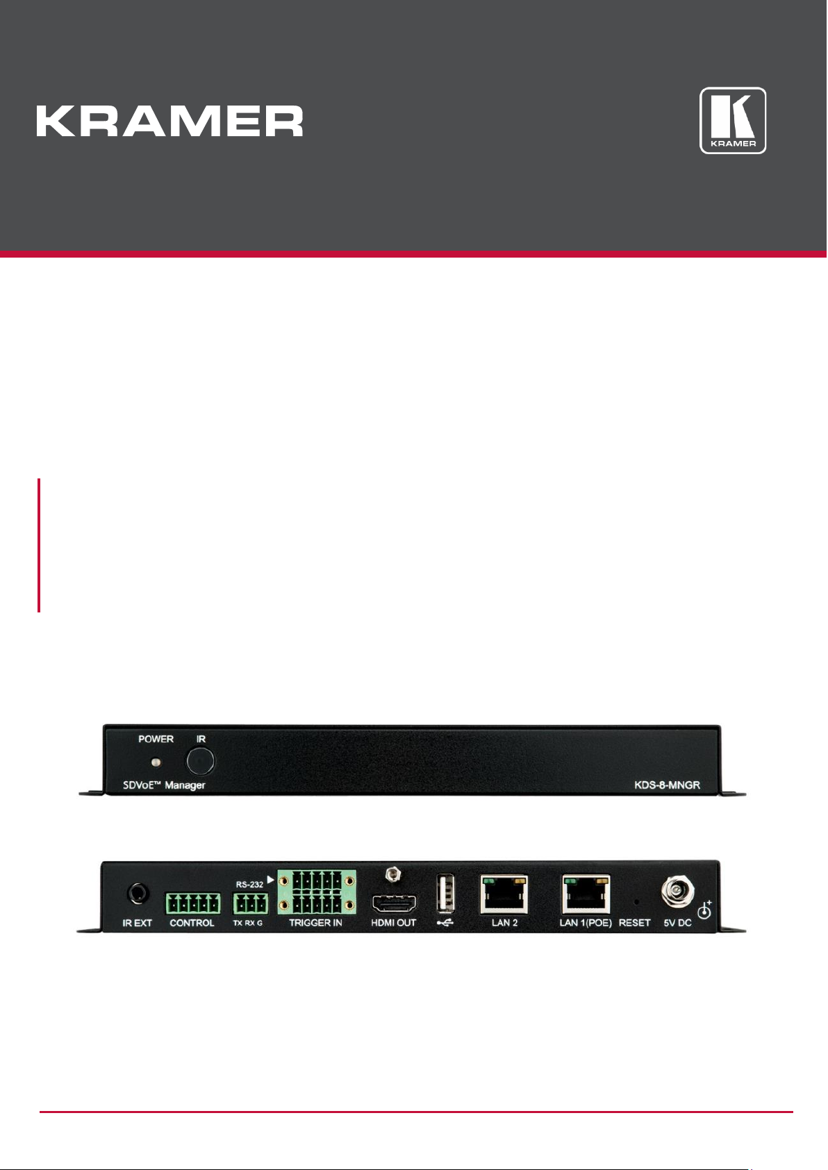
Front and Back Panel
Figure 1: KDS-8-MNGR SDVoE Manager Front Panel
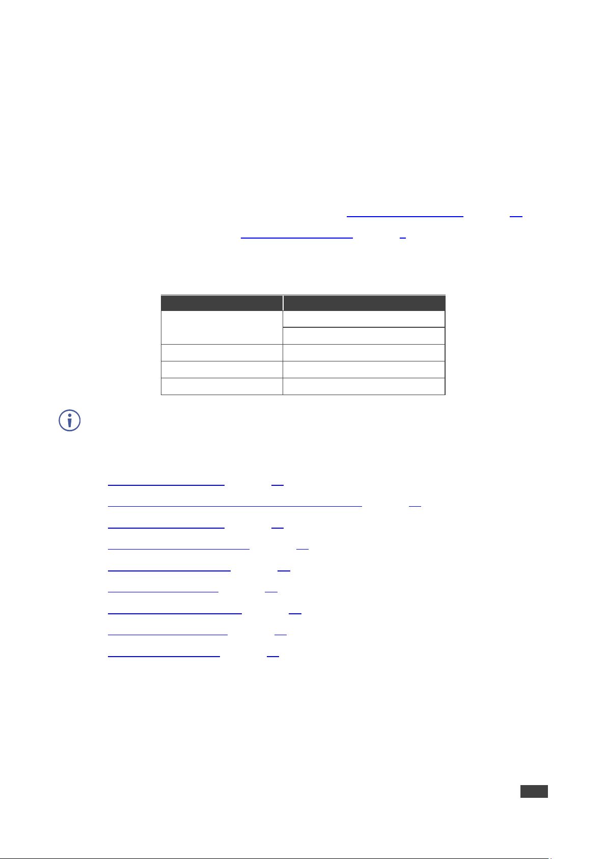
#
Feature
Function
POWER LED
Lights when the device receives power.
IR Window
N/A
Figure 2: KDS-8-MNGR SDVoE Manager Rear Panel
#
Feature
Function
IR EXT Port
For future use.
CONTROL 5-pin
Terminal Block
For future use.
RS-232 3-pin Terminal
Block
Connect to a PC, laptop or other serial control device with a 3-pin adapter
cable to control the unit via RS-232.
TRIGGER IN 10-pin
Terminal Block
Connect to the Trigger Control Keypad (OPTIONAL) or any device with
trigger switch functionality such as window security alarms, motion
detectors, door switches, etc. Each of the 8 trigger inputs will activate the
associated macro (1~8) when triggered.
A minimum of 5V DC is required to activate each trigger.
HDMI™ OUT Port
Connect to a standard HDMI display to view the unit current status
information and access the embedded web pages directly without a PC.
HDMI output is locked to a resolution of 1080p@60Hz.
USB Port
Connect a USB mouse and keyboard to control the unit’s embedded web
pages that are displayed on the HDMI output port. Firmware update via
USB is also supported.
Specialized USB control devices, such as a touch panel, should be
connected before the unit is powered on.
LAN 2 Port
Connect directly, or through a network switch, to your PC/ laptop to control
the unit via embedded web pages/Telnet.
1 2 3 4 5 6 7 8 9

Kramer Electronics Ltd.
KDS-8-MNGR – Defining KDS-8-MNGR
6
#
Feature
Function
LAN 1(POE) Port
Connect to the SDVoE units’ 10G Network through dedicated network
switch, to enable detection and control over those units.
If the connected network switch supports the IEEE 802.3af 2003 PoE
(Power over Ethernet) standard, KDS-8-MNGR can optionally be
powered directly via this Ethernet port.
FACTORY RESET
Press and hold for 3 seconds to reset the unit to its factory defaults,
including Ethernet settings.
While the reset is in process, the front panel LEDs flash. Once the reset
is complete, the unit returns to normal operation.
5V DC Port
Plug the 5V DC power adapter into the unit and connect it to an AC wall
outlet for power. (Optional, not required if the unit is powered via PoE).
10
11
12
Kramer Electronics Ltd.
KDS-8-MNGR – Connecting KDS-8-MNGR
7
Connecting KDS-8-MNGR
Always switch off the power to each KDS-8 device before connecting it to your
KDS-8-MNGR. After connecting your KDS-8-MNGR, connect its power and then switch on
the power to each device.
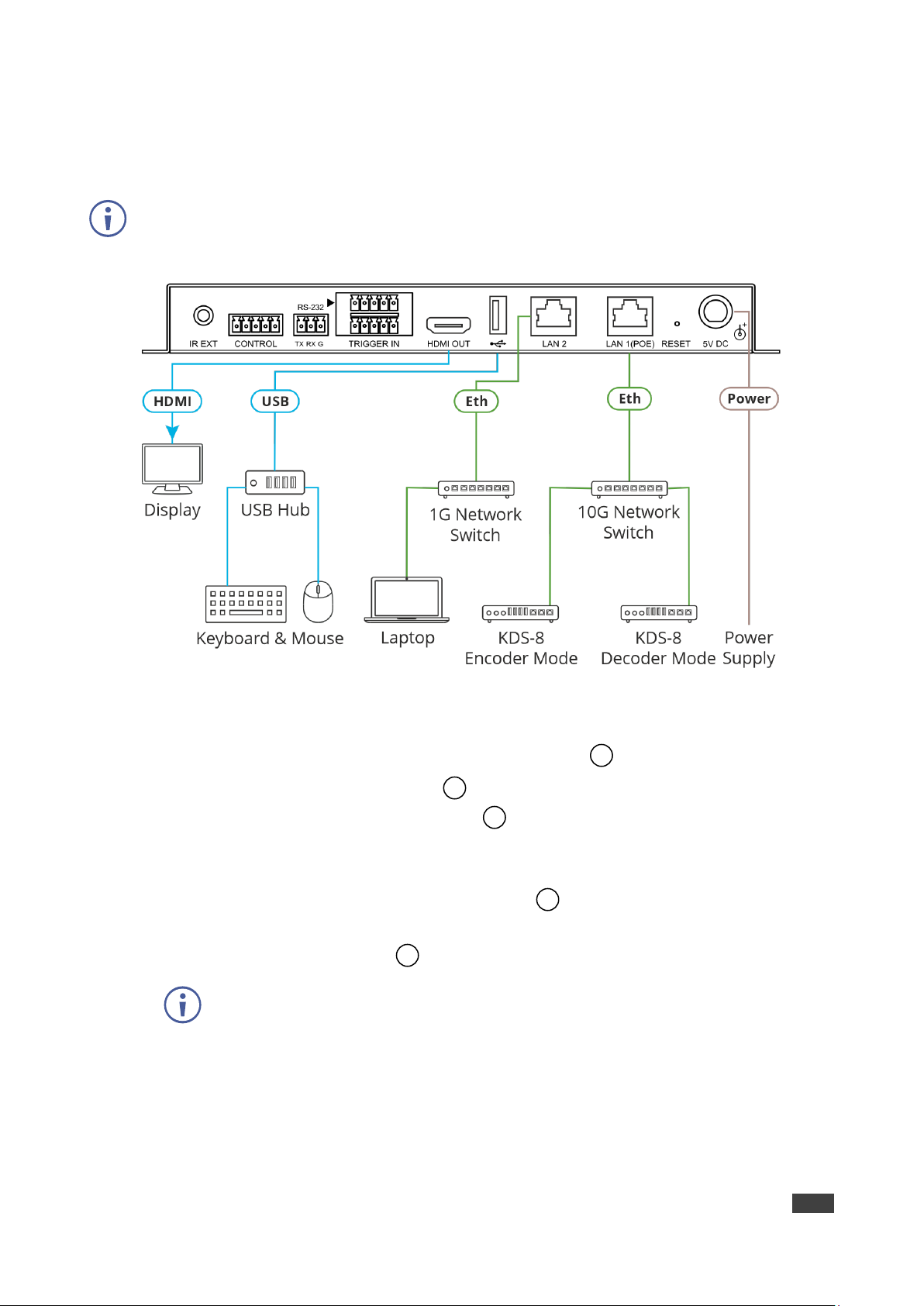
Figure 3: Connecting to the KDS-8-MNGR
To connect KDS-8-MNGR as illustrated in the above example:
1. Connect an HDMI acceptor to the HDMI OUT connector .
2. Connect the USB port to a USB Hub that is connected to a keyboard and mouse.
3. Connect Ethernet LAN 2 RJ-45 connector to a 1G Network switch that is connected
to a laptop.
Alternatively, you can connect LAN 2 directly to a laptop.
4. Connect Ethernet LAN 1 (PoE) RJ-45 Connector to a 10G Network switch that is
connected to KDS-8 (or KDS-8F) encoders and decoders.
5. Connect the 5V DC connector power adapter to the device and the mains electricity.
If the unit is powered via PoE (PD) there is no need to connect the power
adapter.
7 8 10
12
9
Kramer Electronics Ltd.
KDS-8-MNGR – Connecting KDS-8-MNGR
8
RS-232 Pinout and Defaults
Serial Port Default Settings
Unit Control
Serial Output
Baud Rate
19200
3-pin Terminal Block
5-pin Terminal Block
Data Bits
8
Parity Bits
None
Stop Bits
1
Flow Control
None
Operating via Ethernet
You can connect to KDS-8-MNGR via Ethernet using either of the following methods:
• Directly to the PC using a crossover cable (see Connecting Ethernet Port Directly to a
PC on page 8).
• Via a network hub, switch, or router, using a straight-through cable (see Connecting
Ethernet Port via a Network Hub on page 10).
If you want to connect via a router and your IT system is based on IPv6, speak to your IT
department for specific installation instructions.
Connecting Ethernet Port Directly to a PC
You can connect the Ethernet port of KDS-8-MNGR directly to the Ethernet port on your PC
using a crossover cable with RJ-45 connectors.
This type of connection is recommended for identifying KDS-8-MNGR with the factory
configured default fallback IP address.
After connecting KDS-8-MNGR to the Ethernet port, configure your PC as follows:
1. Click Start > Control Panel > Network and Sharing Center.
2. Click Change Adapter Settings.
3. Highlight the network adapter you want to use to connect to the device and click Change
settings of this connection.
The Local Area Connection Properties window for the selected network adapter appears
as shown in Figure 4.

Kramer Electronics Ltd.
KDS-8-MNGR – Connecting KDS-8-MNGR
9
Figure 4: Local Area Connection Properties Window
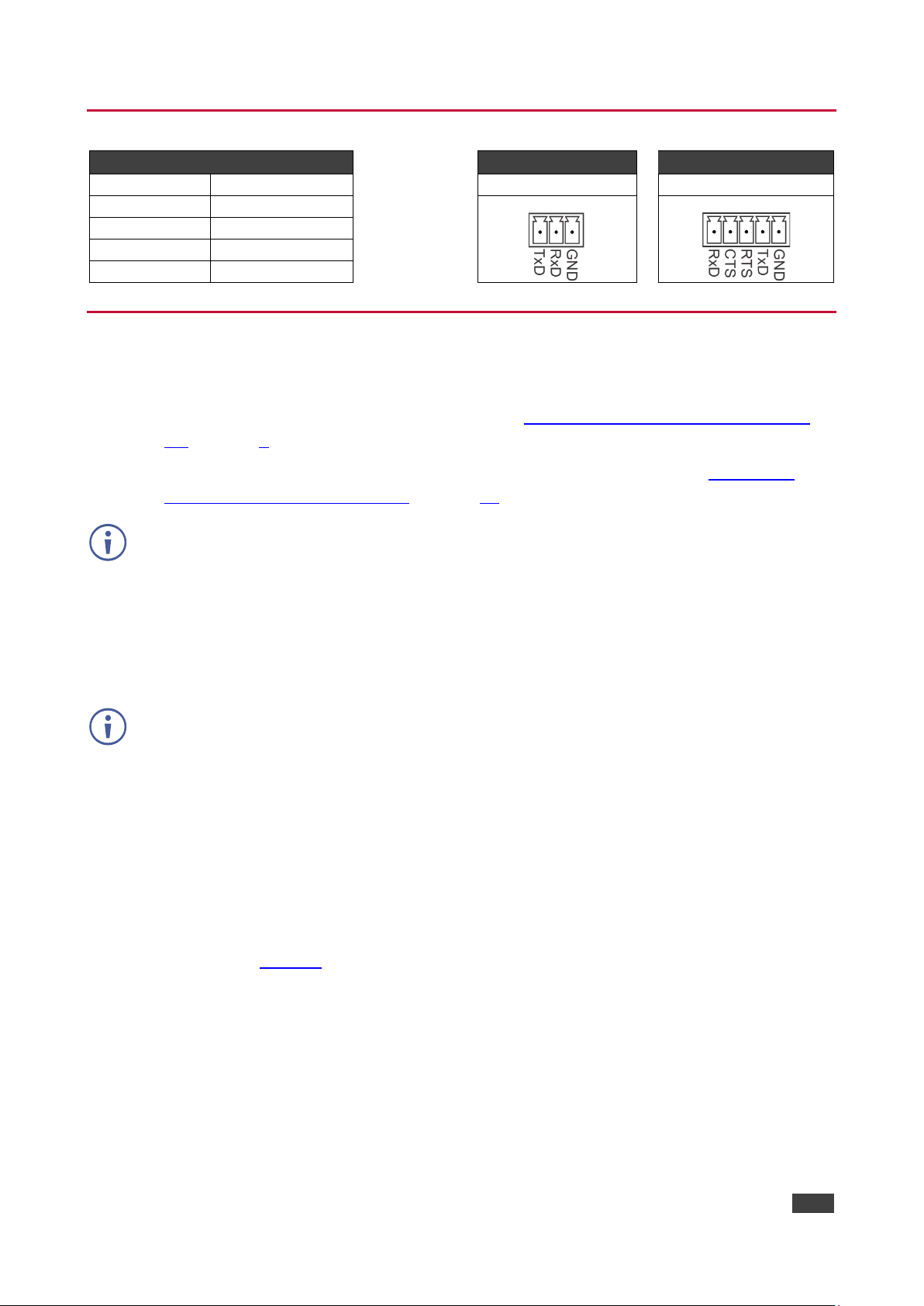
4. Highlight either Internet Protocol Version 6 (TCP/IPv6) or Internet Protocol Version 4
(TCP/IPv4) depending on the requirements of your IT system.
5. Click Properties.
The Internet Protocol Properties window relevant to your IT system appears as shown in
Figure 5 or Figure 6.
Figure 5: Internet Protocol Version 4 Properties Window
Kramer Electronics Ltd.
KDS-8-MNGR – Connecting KDS-8-MNGR
10
Figure 6: Internet Protocol Version 6 Properties Window
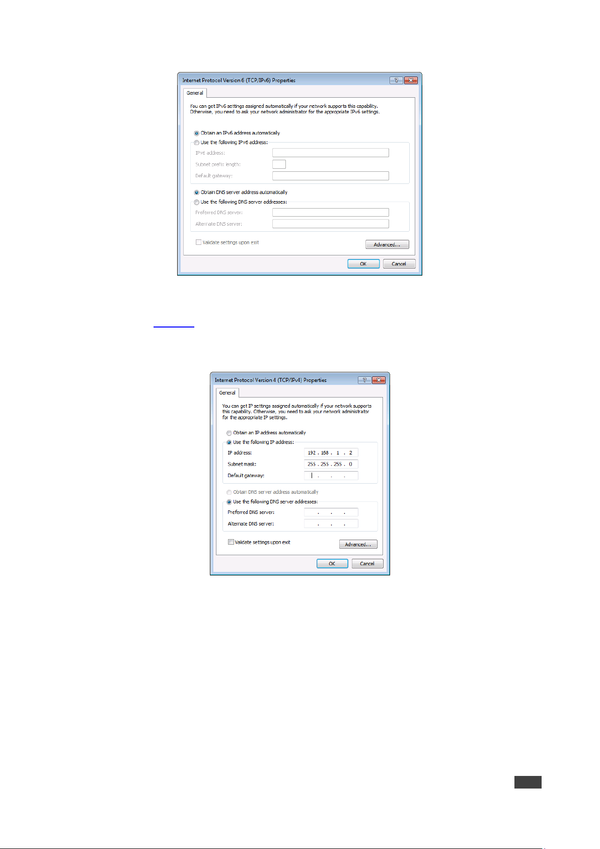
6. Select Use the following IP Address for static IP addressing and fill in the details as
shown in Figure 7.
For TCP/IPv4 you can use any IP address in the range 192.168.1.1 to 192.168.1.255
(excluding 192.168.1.39).
Figure 7: Internet Protocol Properties Window
7. Click OK.
8. Click Close.
Connecting Ethernet Port via a Network Hub or Switch
You can connect the Ethernet port of KDS-8-MNGR to the Ethernet port on a network hub or
using a straight-through cable with RJ-45 connectors.
Configuring Ethernet Port
You can set the Ethernet parameters via the embedded Web pages.
Kramer Electronics Ltd.
KDS-8-MNGR – Using Embedded Web Pages
11
Using Embedded Web Pages
KDS-8-MNGR can be operated and controlled remotely using the embedded Web pages. The
Web pages are accessed using a Web browser and an Ethernet connection. By default,
KDS-8-MNGR is set to DHCP.
Before attempting to connect:
• If required, discover the device IP Address (see Discovering IP Address on page 13).
• Perform the procedures in Operating via Ethernet on page 8.
• Ensure that your browser is supported.
The following operating systems and Web browsers are supported:
Operating Systems
Browser
Windows 10
Chrome (Recommended)
Firefox
Mac
Safari
iOS
Safari
Android
Chrome
Some features might not be supported by some mobile device operating systems.
KDS-8-MNGR enables performing the following:
• Discovering IP Address on page 13.
• Monitoring and Controlling Decoders and Encoders on page 14.
• Configuring the System on page 30.
• Configuring System Settings on page 33.
• Configuring Transmitters on page 45.
• Configuring Receivers on page 47.
• Defining Output Resolution on page 49.
• Configuring Video Walls on page 50.
• Configuring Multiviews on page 51.

Kramer Electronics Ltd.
KDS-8-MNGR – Using Embedded Web Pages
12
To use the browser:
1. Open your Internet browser.
2. Type the IP number of the device, or its hostname, in the Address bar of your browser.
For example,:
The device operation page appears.
After connecting to the embedded pages address in a web browser, the embedded pages
load and display the System tab.
To Access the embedded web pages:
1. Click Login to open the authentication window.
2. Enter the appropriate User Name and Password (admin) and click Enter.
If a keyboard is not available, such as when using a touch screen, an on-screen
keyboard can be activated by clicking on the keyboard icon ( ).
The default user name and password is admin.
Figure 8: Accessing the Embedded Web Pages

Kramer Electronics Ltd.
KDS-8-MNGR – Using Embedded Web Pages
13
Once you are logged-in, the menu tabs appear to the left of each page.
Figure 9: Menu Tabs
To logout:
1. In the System tab click Logout.
When not logged in, only the Monitor & Control and System tabs are available.
Discovering IP Address
You can discover the IP address either by connecting and then sending RS-232 commands
via the KDS-8-MNGR RS-232 port (see RS-232 and Telnet Commands on page 58), or via
the HDMI output.
To discover or change the IP address via HDMI output:
1. Connect the KDS-8-MNGR HDMI output to a display. The System tab in the offline
embedded web pages appears (only Monitor & Control and System tabs are displayed
offline).
2. View the IP address or change it as follows:
a. Connect a mouse to the USB port on the rear panel.
b. Click to open a keyboard on-screen to enter text.
c. Click Login. The Login window appears.
Figure 10: Login Window

Kramer Electronics Ltd.
KDS-8-MNGR – Using Embedded Web Pages
14
d. Click mouse in User Name text box. On-screen keyboard opens.
e. Enter the User Name (admin, by default).
f. Move cursor to Password text box.
g. Enter the Password (admin, by-default).
h. Click Enter.
3. Change Network settings as desired.
Discovered IP address can be used to access embedded web pages online.
Monitoring and Controlling Decoders and Encoders
The Monitor & Control tab provides easy to use drag-and-drop control over all basic routing
functions of the KDS-8 encoders and decoders that have been detected within the local
network and enables performing the following actions:
• Routing Video on page 15.
• Routing a Video Wall on page 17.
• Routing a Multi-viewer on page 18.
• Routing HDMI Audio on page 19.
• Routing Analog Audio on page 22.
• Pairing USB Hosts and Devices on page 24.
• Routing IR Signals on page 26.
• Routing RS-232 Signals on page 27.
• Activating a Macro on page 29.
In all the sections (except for the Routing Video section), transmitters (encoders) are
represented by the source icon ( ) and receivers (decoders) are represented by the display
icon ( ). Each of this tab’s sections control the routing of a different type of interface of
KDS-8 and KDS-8F.
Units that were previously a part of the system, but are not currently detected will still be
displayed, however they will have a disconnected icon ( ) and cannot be used for routing.
Kramer Electronics Ltd.
KDS-8-MNGR – Using Embedded Web Pages
15
Routing Video
Drag and drop detected encoders and decoders to control video routing in the system.
The Video page includes two main areas. The:
• Video Transmitter area, which includes drag-and-drop depiction buttons for all the
encoders that are detected by the system, and a multi-option stop button to stop video
transmission.
• Video Receiver area, which includes drag-and-drop depiction buttons for all the
decoders that are detected by the system, and a Stop button to stop one or all output
streams from being displayed.
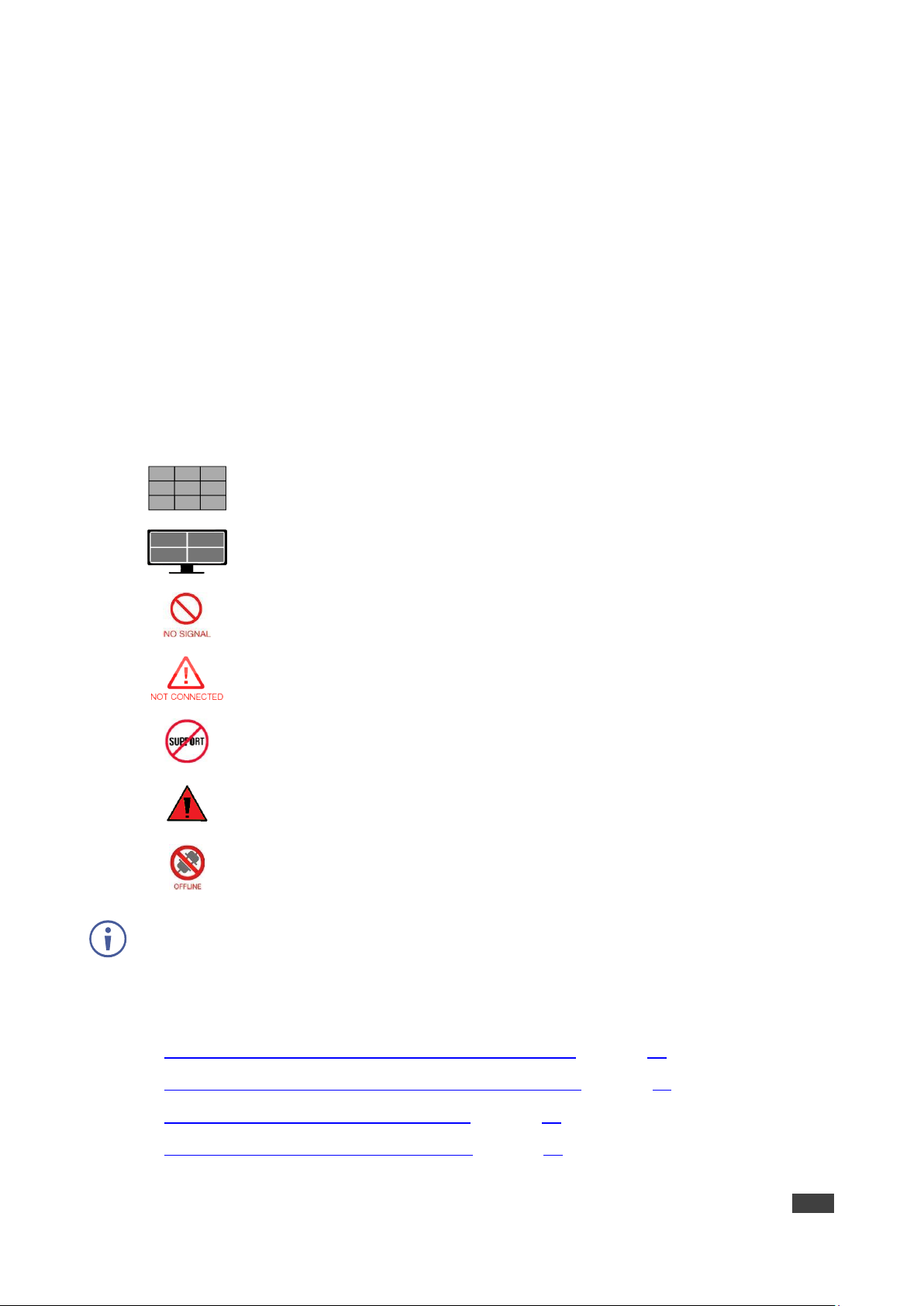
Each encoder and decoder box is depicted as a small-sized, low-framerate, video thumbnail
indicating which video is currently active, or can be represented as follows to indicate that:
The encoder is in the video wall mode.
The encoder is in the Multiviewer mode.
The encoder current input has no live source connected.
The decoder does not have an active display connected.
The encoder/decoder does not support the video thumbnail feature.
The encoders’ source streams are collectively exceed the 10Gbps bandwidth
limitation.
The encoder/decoder is offline or currently not detected by KDS-8-MNGR.
KDS-8-MNGR features automatic bandwidth reduction if the total source streaming exceeds
10Gbps. In case this happens, we recommend that you reduce the source resolution, frame
rate or bit depth to maintain stable video quality on the display.
The Video page enables performing the following actions:
• Streaming an HDMI Audio Source to a Single Decoder on page 20.
• Streaming an HDMI Audio Source to Multiple Decoders on page 21.
• Stopping an HDMI Audio Source Stream on page 21.
• Stopping an HDMI Audio Display Stream on page 21.

Kramer Electronics Ltd.
KDS-8-MNGR – Using Embedded Web Pages
16
Streaming a Source to a Single Decoder
To route a source (on a detected encoder) to a display on an encoder:
1. In the Menu tabs, select Monitor & Control. The Video page appears.
Figure 11: Monitor & Control Tab – Video Page
2. Click and drag a source button in the transmitter area to the preferred display in the
receiver area.
3. Release the mouse button.
The routed source name appears below the display name.
The selected source and routed displays change their color.
You can also drag and drop display decoders to an encoder source on the transmitter side to
activate a new streaming route.
The source on the encoder is streamed to the decoder.
Streaming a Source to Multiple Decoders
To route a source (on a detected encoder) to multiple encoders:
1. In the Menu tabs, select Monitor & Control. The Video page appears.
2. Click and drag a source button in the transmitter area to a predefined Video group or an
All button in the receiver area.
3. Release the mouse button.
The routed source name appears below the group name.
The source on the encoder is streamed to multiple decoders.

Kramer Electronics Ltd.
KDS-8-MNGR – Using Embedded Web Pages
17
Stopping a Video Source Stream
You may need to stop one or all the video streams coming from a source.
To stop a video source stream:
1. In the Menu tabs, select Monitor & Control. The Video page appears.
2. Click (Stop selection button) at the lower part of the transmitter area and cycle to the
required option:
▪ All Stop stops all stream types from the selected source.
▪ Native Stop stops only the full resolution primary video stream.
▪ Multiview Stop stops only the secondary video stream used by multiviewer layouts.
3. Click and drag the source to the selected Stop button. Streaming from that source stops.
To stop a stream type from ALL video streams simultaneously, drag All down to the
All Stop button.
Source/s streaming has stopped.
Stopping a Video Display Stream
To stop a video display stream:
1. In the Menu tabs, select Monitor & Control. The Video page appears.
2. Click and drag the display to the Stop button.
3. Release the mouse. Streaming to that display stops.
Drag All button down to the Stop button to stop all streaming.
Display streaming has stopped.
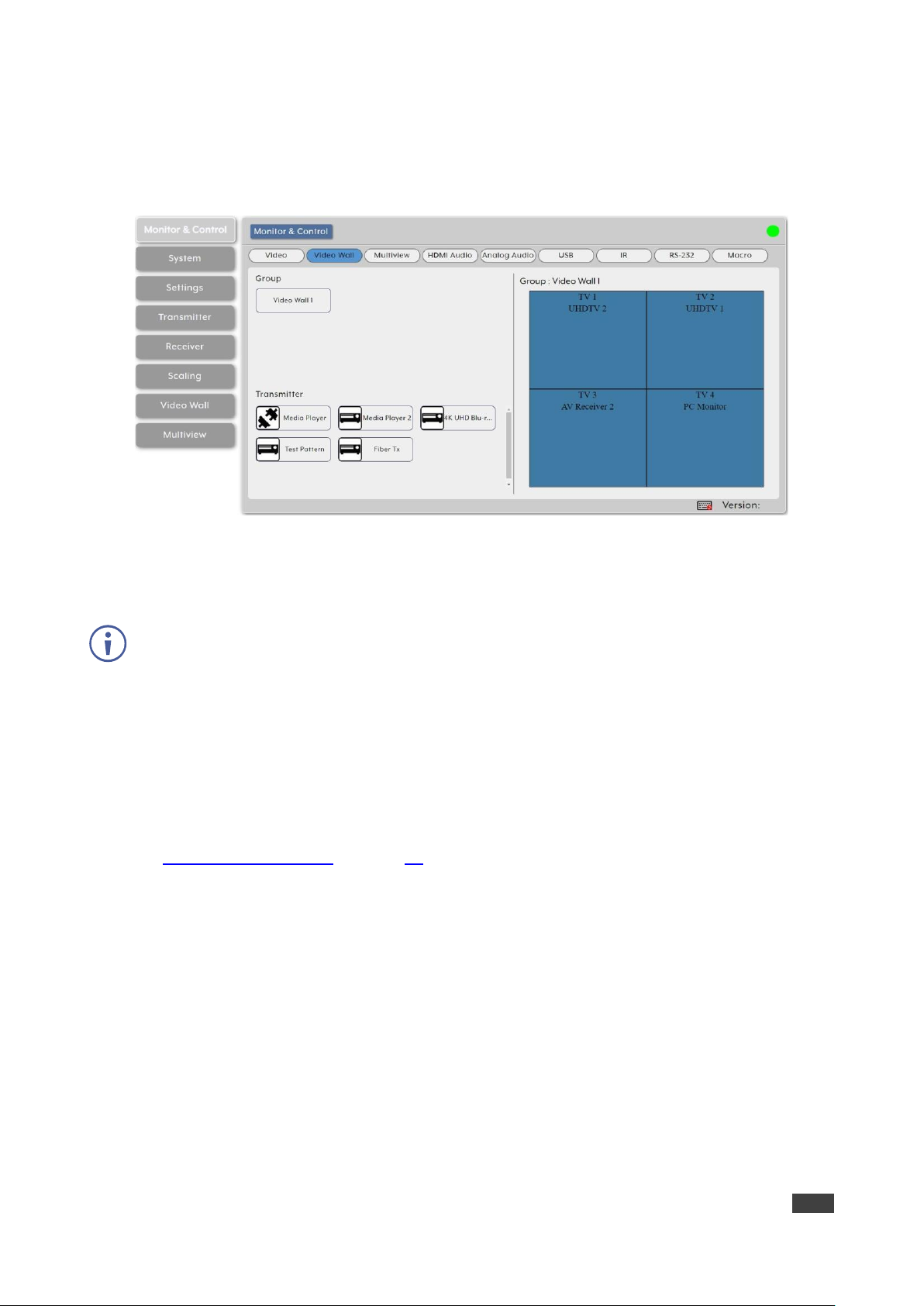
Routing a Video Wall
Drag and drop detected encoder sources and decoder displays to control predefined video
wall routing in the system. Go to Configuring Video Walls on page 50 to define a video wall
group.
The Video Wall section includes three main areas. The:
• Group area, which includes all the currently defined video wall groups Click a group icon
to display a simplified graphical representation of the video wall on the video wall view
on the right side of the page. For example, Video Wall 1 group shows as Group: Video
Wall 1 on the right side of the Video wall section.
• Transmitter area, which includes all the available decoders.
• Video wall view area, representing the selected video wall.
Kramer Electronics Ltd.
KDS-8-MNGR – Using Embedded Web Pages
18
To assign a source to a video wall group:
1. In the Menu tabs, select Monitor & Control. The Video section appears.
2. Click Video wall. The Video Wall section appears.
Figure 12: Monitor & Control Tab – Video Wall Page
3. Drag a source from the Transmitter area to the required video wall group.
The source on the encoder is streamed to the Video Wall.
Dragging a source to an inactive video wall group, automatically activates all of that video wall
displays.
Routing a Multi-viewer
Set the streaming in a multi-viewer by dragging and dropping the Multiview preset to an
available decoder display and also by dragging and dropping a decoder source over to
Multiview windows.
Before routing inputs to Multiview windows, you need to define a Multiview preset
(see Configuring Multiviews on page 51).
The Multiview page includes four main areas. The:
• Preset area, which includes all currently defined multiview presets.
• Receiver area, which includes all the decoder displays that available to display the
muliview preset.
• Multiviewer view area, which shows a simplified graphical representation of the
currently selected multiview preset. An active preset appears has green windows that
show a faded video thumbnail of the source that is currently selected.
• Transmitter area, which includes all the encoder sources. Unavailable sources are
displayed in red.

Kramer Electronics Ltd.
KDS-8-MNGR – Using Embedded Web Pages
19
To assign a source to a Preset Multiviewer:
1. In the Menu tabs, select Monitor & Control. The Video section appears.
2. Click Multiview. The Video Wall section appears.
Figure 13: Monitor & Control Tab – Multiview Section
3. From the Preset list, select a Multiview preset (for example, Multiview 1) and drag the
selected preset to a selected decoder display (or to all the available displays), listed
under Receiver (for example, UHDTV 1).
The multiview preset windows are displayed on the right-side of the page (green
windows).
4. From the transmitter list of available encoder sources, drag a source to a window as
needed.
Note that a single source cannot be simultaneously displayed in differently sized
windows or in multiple presets at different output resolutions.
5. Select a source for each of the Multiview windows.
The sources on the encoders are streamed to the Multiview windows.
Routing HDMI Audio
You can route the HDMI audio signal independently via drag-and-drop of the detected
encoders and decoders.
Bitstream audio is supported when the decoder HDMI audio device is set to “HDMI Audio
(Follow Video in Genlock Mode)”.
The HDMI Audio page includes two main areas. The:
• HDMI Audio Transmitter area, which includes drag-and-drop buttons for all the encoder
sources that are detected by the system, and a multi-option stop button to stop video
transmission.

Kramer Electronics Ltd.
KDS-8-MNGR – Using Embedded Web Pages
20
• HDMI Audio Receiver area, which includes drag-and-drop buttons for all the decoder
displays that are detected by the system, and a Stop button to stop one or all audio
streams from being displayed.
The HDMI Audio page enables performing the following actions:
• Streaming an HDMI Audio Source to a Single Decoder on page 20.
• Streaming an HDMI Audio Source to Multiple Decoders on page 21.
• Stopping an HDMI Audio Source Stream on page 21.
• Stopping an HDMI Audio Display Stream on page 21.
Streaming an HDMI Audio Source to a Single Decoder
To route an HDMI audio source (on a detected encoder) to a display on an encoder:
1. In the Menu tabs, select Monitor & Control. The Video page appears.
2. Click HDMI Audio. The HDMI Audio page appears.
Figure 14: Monitor & Control Tab – HDMI Audio Page
3. Click and drag a source button in the transmitter area to the preferred display in the
receiver area.
4. Release the mouse button.
The routed source name appears below the display name.
The selected source and routed displays change their color.
You can also drag and drop display decoders to an encoder source on the transmitter side to
activate a new streaming route.
The source on the encoder is streamed to the decoder.

Kramer Electronics Ltd.
KDS-8-MNGR – Using Embedded Web Pages
21
Streaming an HDMI Audio Source to Multiple Decoders
To route an HDMI audio source (on a detected encoder) to multiple encoders:
1. In the Menu tabs, select Monitor & Control. The Video page appears.
2. Click HDMI Audio. The HDMI Audio page appears.
3. Click and drag a source button in the transmitter area to a predefined HDMI audio group
or an All button in the receiver area.
4. Release the mouse button.
The routed source name appears below the group name.
The source on the encoder is streamed to multiple decoders.
Stopping an HDMI Audio Source Stream
You may need to stop one or all the video streams coming from a source.
When the HDMI Audio of an encoder is set to “Follow Video in Genlock Mode”, and scaling on
that output has been disabled (Bypass), the audio output on that receiver cannot be stopped
by using this control.
To stop a HDMI audio source stream:
1. In the Menu tabs, select Monitor & Control. The Video page appears.
2. Click HDMI Audio. The HDMI Audio page appears.
3. Click and drag an HDMI audio source button (or the All button) to the Stop button in the
transmitter area. Streaming from that source stops.
Source/s streaming has stopped.
Stopping an HDMI Audio Display Stream
To stop an HDMI audio stream on a display:
1. In the Menu tabs, select Monitor & Control. The Video page appears.
2. Click HDMI Audio. The HDMI Audio page appears.
3. Click and drag the display to the Stop button.
4. Release the mouse. Streaming to that display stops.
Drag All button down to the Stop button to stop all streaming.
Display streaming has stopped.

Kramer Electronics Ltd.
KDS-8-MNGR – Using Embedded Web Pages
22
Routing Analog Audio
You can route analog audio signals via drag-and-drop of the detected encoders and
decoders.
Bitstream audio is supported when the decoder HDMI audio device is set to “HDMI Audio
(Follow Video in Genlock Mode)”.
The Analog Audio page includes two main areas. the:
• Analog Audio Transmitter area, which includes drag-and-drop buttons for all the
encoder sources that are detected by the system, and a multi-option stop button to stop
video transmission.
• Analog Audio Receiver area, which includes drag-and-drop buttons for all the decoder
displays that are detected by the system, and a Stop button to stop one or all audio
streams from being displayed.
If a selected audio source for an analog output is set to “HDMI Audio (Stereo Downmix)” that
output will be marked with an exclamation mark (!) and the audio output will mirror the source
set on the HDMI Audio routing page.
The Analog Audio page enables performing the following actions:
• Streaming an Analog Audio Source to a Single Decoder on page 23.
• Streaming an Analog Audio Source to Multiple Decoders on page 23.
• Stopping an Analog Audio Source Stream on page 24.
• Stopping an HDMI Audio Display Stream on page 24.

Kramer Electronics Ltd.
KDS-8-MNGR – Using Embedded Web Pages
23
Streaming an Analog Audio Source to a Single Decoder
To route an analog audio source (on a detected encoder) to a display on an encoder:
1. In the Menu tabs, select Monitor & Control. The Video page appears.
2. Click Analog Audio. The Analog Audio page appears.
Figure 15: Monitor & Control Tab – Analog Audio Page
3. Click and drag a source button in the transmitter area to the preferred display in the
receiver area.
4. Release the mouse button.
The routed source name appears below the display name.
The selected source and routed displays change their color.
You can also drag and drop display decoders to an encoder source on the transmitter side to
activate a new streaming route.
The source on the encoder is streamed to the decoder.
Streaming an Analog Audio Source to Multiple Decoders
To route an analog audio source (on a detected encoder) to multiple encoders:
1. In the Menu tabs, select Monitor & Control. The Video page appears.
2. Click Analog Audio. The HDMI Audio page appears.
3. Click and drag a source button in the transmitter area to a predefined HDMI audio group
or an All button in the receiver area.
4. Release the mouse button.
The routed source name appears below the group name.
The source on the encoder is streamed to multiple decoders.

Kramer Electronics Ltd.
KDS-8-MNGR – Using Embedded Web Pages
24
Stopping an Analog Audio Source Stream
You may need to stop one or all the video streams coming from a source.
To stop a video source stream:
1. In the Menu tabs, select Monitor & Control. The Video page appears.
2. Click HDMI Audio. The HDMI Audio page appears.
3. Click and drag an HDMI audio source button (or the All button) to the Stop button in the
transmitter area. Streaming from that source stops.
Source/s streaming has stopped.
Stopping an HDMI Audio Display Stream
If the selected audio source for an analog output has been set to “HDMI Audio (Stereo
Downmix)” the audio output can only be stopped from the HDMI Audio page..
To stop an HDMI audio stream on a display:
1. In the Menu tabs, select Monitor & Control. The Video page appears.
2. Click HDMI Audio. The HDMI Audio page appears.
3. Click and drag the display or the All button to the Stop button.
4. Release the mouse. Streaming to that display stops.
Display streaming has stopped.
Pairing USB Hosts and Devices
Use drag-and Drop control to pair USB hosts (such as a PC, laptop etc.) and USB devices
(such as a keyboard, mouse, webcam, etc.) connected to USB ports on detected encoders
and decoders.
If “Simultaneous Mode” is enabled on the USB host port, it can be paired with up to 7 device
endpoints.
If “Simultaneous Mode” is disabled, a USB host port can only be paired with a single USB
device endpoint.
The USB page includes two main areas. The:
• USB Host area, which includes drag-and-drop buttons for all the encoder USB Hosts
that are detected by the system, and a stop button to stop communication from a host.
• USB Device area, which includes drag-and-drop buttons for all the decoder USB device
endpoints and a Stop button to stop communication from a device.

Kramer Electronics Ltd.
KDS-8-MNGR – Using Embedded Web Pages
25
The USB page enables performing the following actions:
• Pairing a Host to a Device on page 25.
• Stopping Communication from a USB Host on page 25.
• Stopping Communication from a USB device on page 26.
Pairing a Host to a Device
To pair a USB host with a USB device:
1. In the Menu tabs, select Monitor & Control. The Video page appears.
2. Click USB. The USB page appears.
Figure 16: Monitor & Control Tab – USB Page
3. Click and drag a USB host button from the Host side to a USB device on the Device side.
4. Release the mouse. The active USB host name appears below the group name.
The selected host and routed devices change their color.
USB hosts and devices are paired.
Stopping Communication from a USB Host
To stop communication from a USB host:
1. In the Menu tabs, select Monitor & Control. The Video page appears.
2. Click USB. The USB page appears.
3. Click and drag a USB host button to the Stop button in the Host area.
Communication from USB host has stopped.
Kramer Electronics Ltd.
KDS-8-MNGR – Using Embedded Web Pages
26
Stopping Communication from a USB device
To stop communication from a USB device:
1. In the Menu tabs, select Monitor & Control. The Video page appears.
2. Click USB. The USB page appears.
3. Click and drag a USB device to the Stop button in the Device area.
Communication from USB device has stopped.
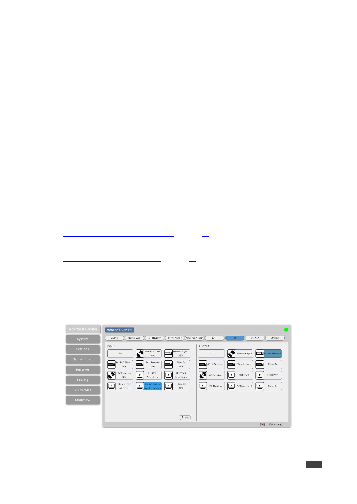
Routing IR Signals
Route IR inputs and outputs on detected encoders and decoders via drag-and Drop control.
The IR page includes two main areas. The:
• IR Input area, which includes drag-and-drop buttons for all the encoder IR input ports
that are detected by the system, and a stop button to stop IR streaming to the encoders.
• IR Output area, which includes drag-and-drop buttons for all the decoder IR output
ports.
Use IR page to perform the following actions:
• Streaming Global Broadcast IR Inputs on page 26.
• Connecting IR Out to IR Input on page 27.
• Stopping IR Broadcast Streaming on page 27.
Streaming Global Broadcast IR Inputs
To broadcast an IR input to all available IR outputs:
1. In the Menu tabs, select Monitor & Control. The Video page appears.
2. Click IR. The IR page appears.
Figure 17: Monitor & Control Tab – IR Page
3. Click and drag an IR input button from the Input side to All on the Output side.

Kramer Electronics Ltd.
KDS-8-MNGR – Using Embedded Web Pages
27
4. Release the mouse. The word broadcast appears in the appropriate IR input button.
The selected input and output devices change their color.
IR Input is routed to all available IR outputs.
Connecting IR Out to IR Input
To connect an IR Output to an IR input:
1. In the Menu tabs, select Monitor & Control. The Video page appears.
2. Click IR. The IR page appears.
3. Click and drag an IR output button from the Output side to an input IR on the Input side.
4. Release the mouse. The IR output name appears in the IR input button.
The selected input and output devices change their color.
IR inputs may also be dragged and dropped onto IR outputs to activate a new route.
IR outputs is routed to IR Input.
Stopping IR Broadcast Streaming
To stop IR input signal broadcast:
1. In the Menu tabs, select Monitor & Control. The Video page appears.
2. Click IR. The IR page appears.
3. Click and drag an IR Input button or the All button to the Stop button in the Input area.
IR streaming has stopped.
Routing RS-232 Signals
Route RS-232 signals, via drag and drop, from RS-232 ports on detected encoders to RS-232
ports on detected decoders.
The RS-232 port on a standard extension unit contains one sender (Rx pin) and one receiver
(Tx pin).
You can send one or multiple RS-232 signals from different encoders to a single RS-232 port
on a decoder.
Use the Global Broadcast option If you need to send an RS-232 signal to more than one
decoder.
The RS-232 page includes two main areas. the:
• Sender area, which includes drag-and-drop buttons for all the encoder RS-232 ports that
are detected by the system, and a stop button to stop RS-232 streaming to the encoders.
• Receiver area, which includes drag-and-drop buttons for all the decoder RS-232 output
ports.

Kramer Electronics Ltd.
KDS-8-MNGR – Using Embedded Web Pages
28
Use RS-232 page to perform the following actions:
• Streaming Global Broadcast RS-232 Inputs on page 28.
• Routing RS-232 Output to RS-232 Input on page 28.
• Stopping RS-232 Broadcast Streaming on page 29.
Streaming Global Broadcast RS-232 Inputs
To broadcast an RS-232 input to all available RS-232 outputs:
1. In the Menu tabs, select Monitor & Control. The Video page appears.
2. Click RS-232. The RS-232 page appears.
Figure 18: Monitor & Control Tab – RS-232 Page
3. Click and drag an RS-232 input button from the Sender side to All on the Receiver side.
4. Release the mouse. The word broadcast appears in the appropriate RS-232 input
button.
The selected input and output devices change their color.
RS-232 Input is routed to all available RS-232 outputs.
Routing RS-232 Output to RS-232 Input
To route an RS-232 signal on the Receiver side to an RS-232 input on the sender side:
1. In the Menu tabs, select Monitor & Control. The Video page appears.
2. Click RS-232. The RS-232 page appears.
3. Click and drag an RS-232 output button from the Receiver side to an RS-232 input on the
Sender side.
4. Release the mouse. The RS-232 output name appears in the RS-232 input button.
The selected input and output devices change their color.
RS-232 inputs on the sender side can also be dragged and dropped onto RS-232 outputs to
activate a new route.
RS-232 output is routed to RS-232 Input.

Kramer Electronics Ltd.
KDS-8-MNGR – Using Embedded Web Pages
29
Stopping RS-232 Broadcast Streaming
To stop RS-232 input signal broadcast:
1. In the Menu tabs, select Monitor & Control. The Video page appears.
2. Click RS-232. The RS-232 page appears.
3. Click and drag an RS-232 Input button or the All button to the Stop button in the Input
area.
IR streaming has stopped.
Activating a Macro
You can activate macros that have been pre-defined and stored within the KDS-8-MNGR
using the following simple interface. To define Macros, see Creating Macros on page 35).
Only one macro can be executed at a time.
Activating a Predefined Macro
To activate a Macro:
1. In the Menu tabs, select Monitor & Control. The Video page appears.
2. Click Macro. The RS-232 page appears.
Figure 19: Monitor & Control Tab – Macro Page
3. Click a Macro.
the selected Macro button remains blue until execution completion of the selected
Macro.
Macro is activated.

Kramer Electronics Ltd.
KDS-8-MNGR – Using Embedded Web Pages
30
Configuring the System
Set KDS-8-MNGR IP configuration for both LAN ports, interface language, login and user
management, and firmware update functionality.
KDS-8-MNGR System Tab enables performing the following actions:
• Setting IP Definitions for LAN1 and LAN2 on page 30.
• Running System Basic Commands on page 31.
• Resetting the System on page 31.
• Upgrading the Firmware on page 32.
When not logged in, only the “Monitor & Control” and “System” tabs are available.
Setting IP Definitions for LAN1 and LAN2
Set the IP Mode address, netmask, and gateway Network definitions for each LAN port
(DHCP or Static IP).
When a LAN port is set to DHCP mode, it automatically attempts to obtain proper
configuration information from the local DHCP server. If no DHCP server is available, it will
automatically assign itself an APIPA address from the 169.254.xxx.xxx range.
To configure the Network settings manually:
1. In the Menu tabs, select System. The System page appears.
Figure 20: System page
2. Set IP mode to Static.
3. Manually enter IP Address, Subnet Mask and Gateway.
4. Click Save.
By default, both LAN ports are set to DHCP mode. The current IP address can be verified
using the HDMI output or RS-232 if the Device Discovery software is not available.

Kramer Electronics Ltd.
KDS-8-MNGR – Using Embedded Web Pages
31
Running System Basic Commands
Use predefined system commands to carry out system basic actions.
To run system commands:
1. In the Menu tabs, select System. The System page appears.
2. In the top right area of the system page, click:
▪ Login to log into the embedded web pages.
▪ Logout to exit the embedded web pages.
▪ Change Password to change the admin login password.
▪ Save Config to save the current system configuration as a *.bin file to your local PC.
▪ Upload Config to upload a saved system configuration file. Click Upload Config to
locate the saved *.bin file, then click the “Open” button.
▪ Save Log to generate and save a copy of the current log data in, *.zip format, to your
local PC (this system log file can help diagnose configuration issues or other
problems).
The generated file is password protected and is only intended for use by authorized
technical support.
3. If required, open the drop-down list to select the user language for the embedded web
pages.
Basic commands are carried out.
Resetting the System
KDS-8-MNGR provides several reset options.
To reset the system:
1. In the Menu tabs, select System. The System page appears.
2. In the top right area of the system page, click:
▪ Factory Reset to reset the unit back to its factory default settings.
Factory Reset does NOT clear the transmitter and receiver history tables. To
completely remove old transmitter and receiver units from the system, use the
“Remove” option on the Transmitter and Receiver tabs (see Configuring
Transmitters on page 45 and Configuring Receivers on page 47).
▪ Reset all transmitters to reset all detected transmitters back to their factory default
settings.
▪ Reset all receivers to reset all detected receivers back to their factory default
settings.
▪ Reboot System to reboot this KDS-8-MNGR unit.

Kramer Electronics Ltd.
KDS-8-MNGR – Using Embedded Web Pages
32
▪ Reboot all transmitters to reboot all detected transmitters.
▪ Reboot all receivers to reboot all detected receivers.
3. View the KDS-8-MNGR S/N (Serial Number).
System reset/reboot is complete.
Upgrading the Firmware
Use KDS-8-MNGR to remotely update the firmware of this unit and the detected transmitters
and receivers in the system. the Kit Plugin option is currently not available.
The update process can take several minutes to complete, especially if there are multiple
transmitters and receivers in the system.
Do not power off any units during the update process.
KDS-8-MNGR enables performing the following firmware upgrades:
• Upgrading KDS-8-MNGR Firmware on page 32.
• Upgrading Transmitter/Receiver Firmware on page 33.
Upgrading KDS-8-MNGR Firmware
To upgrade the KDS-8-MNGR firmware:
1. In the Menu tabs, select System. The System page appears.
Figure 21: System Page
2. Under IP Master Controller (KDS-8-MNGR), click Choose file. The file selection window
opens.
3. Select the firmware update file (*.bin format) located on your local PC.
4. Click Upgrade to begin the firmware update process. Once the firmware update process
has completed the unit reboots.
Firmware upgrade is complete.

Kramer Electronics Ltd.
KDS-8-MNGR – Using Embedded Web Pages
33
Upgrading Transmitter/Receiver Firmware
You can upgrade the firmware of all the detected transmitters/receivers at once.
To upgrade the transmitter/receiver firmware:
1. In the Menu tabs, select System. The System page appears.
2. Under transmitter, click Choose file. The file selection window opens.
3. Select the transmitter/receiver firmware update file (*.apz format) located on your local
PC.
4. Click Upgrade All (under transmitters or under receivers, depending on the chosen file)
to begin the firmware update process. Once the firmware update process has completed
the transmitters/receivers reboot.
Firmware upgrade is complete.
The transmitter/receiver firmware is stored within the KDS-8-MNGR after upload and is also
used when performing individual unit updates via the Transmitter and Receiver tabs.
Configuring System Settings
KDS-8-MNGR enables configuration of different internal systems and interfaces, including
group and macro creation, manual IR and RS-232 command broadcasting, I/O trigger
assignment, EDID management, and setting the system’s clock and event scheduling.
KDS-8-MNGR enables performing the following actions:
• Creating Groups on page 33.
• Creating Macros on page 35.
• Sending RS-232/IR commands on page 36.
• Assigning I/O Triggers on page 37.
• Managing EDID on page 38.
• Setting the Time on page 39.
• Managing Scheduling on page 40.
Creating Groups
Groups are listed Under Device Group Name in the Group page. You can include multiple
receiving endpoints in one group for simple, single click targets, for routing A/V, USB or IR/RS232 sources. Once created, each group appears within the appropriate section of the Monitor
& Control Tab (see Monitoring and Controlling Decoders and Encoders on page 14) beside
standard receivers.

Kramer Electronics Ltd.
KDS-8-MNGR – Using Embedded Web Pages
34
To create a group:
1. In the Menu tabs, select Settings. The Group page appears.
Figure 22: Settings Tab – Group Page
2. Click to create a new group.
Click to edit an existing group.
Click to delete a group
3. Enter group details:
▪ Next to Order, open the drop-down box to select the group order (also use to change
the order of existing groups).
Groups are displayed in the Monitor & Control tab in the same order.
▪ Enter Group Name.
▪ Select Group Type from the drop-down list. Group type determines the signal type for
this group: Video/Audio, USB, and IR/RS-232.
This selection affects the type of receiver endpoints available within the Device List.
▪ In the Device area, which lists all the available decoder acceptors (displays), click an
acceptor to move it to the Group area, which lists all the acceptors in the selected
group. Click All to move all the devices to the group.
▪ In the Group area, which lists the devices in the group, click a device button to
remove it from the group (back to the Device area) or click Remove All to remove all
of them.
4. Click Save Group.
A group is saved to the list.

Kramer Electronics Ltd.
KDS-8-MNGR – Using Embedded Web Pages
35
Creating Macros
KDS-8-MNGR can create operational command sequences that can be activated via Kramer
Control, external triggers, or from within the embedded web pages. Macros are a flexible and
powerful tool. They can be as simple as selecting a new input for a decoder or a complex
sequence of source, resolution, mode, and audio changes executed in sequence. Up to 16
macros can be defined, each containing up to 64 commands.
To create a Macro:
1. In the Menu tabs, select Settings. The Group page appears.
2. Click Macro. The Macro page appears.
Figure 23: Settings Tab – Macro Page
3. Click to create a new macro.
Click to edit an existing macro.
Click to delete a macro.
4. Next to Order, open the drop-down box to select the macro order (also use to change
the order of existing macros).
Macros are displayed in the Monitor & Control tab in the same order and when
assigning IR/trigger functionality.
5. Enter Macro Name.
6. Under New Command:
a. Click New.
b. Select the command type from the drop-down list.
c. Select the other parameters relevant for this command type (Transmitter and
Receiver for this command).
d. Set the command order in the macro sequence.
Kramer Electronics Ltd.
KDS-8-MNGR – Using Embedded Web Pages
36
e. Click Add. The command is added to the Macro Commands sequence.
7. Click Save Macro.
8. If required, click Execute to test the Macro.
A Macro is saved to the Macro Name list.
Sending RS-232/IR commands
You can manually send single RS-232 or IR commands to specific decoder endpoints within
the system.
To send single RS-232 or IR commands:
1. In the Menu tabs, select Settings. The Group page appears.
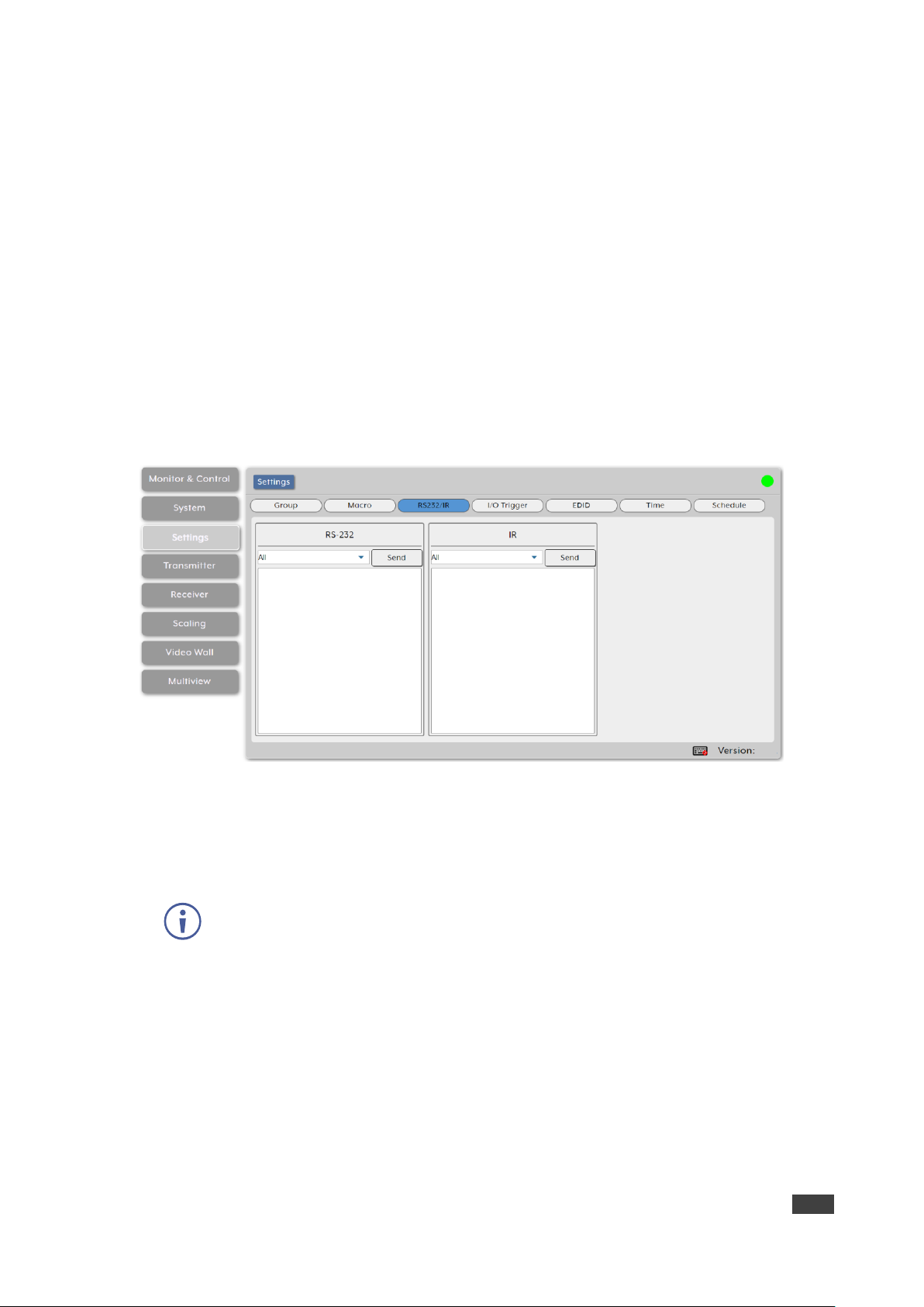
2. Click RS232/IR. The RS232/IR page appears.
Figure 24: Settings Tab – RS232/IR Page
3. For RS-232:
a. Select the command target from the drop-down box.
b. Enter or copy the command to the empty area below RS-232.
To transmit hex data, each ASCII hex pair (octet) must be preceded by “\x”. For
example, a carriage return would be “\x0D”.
c. Click Send to send the command immediately.
4. For IR:
a. Select the command target from the drop-down box.
b. Enter or copy the command to the empty area below IR.
c. Click Send to send the command immediately.
RS-232/IR command is sent.

Kramer Electronics Ltd.
KDS-8-MNGR – Using Embedded Web Pages
37
Assigning I/O Triggers
You can assign macros (see Creating Macros on page 35) to each of the 8 trigger inputs on
the unit as well as to the 8 IR remote buttons.
To assign a macro to a trigger:
1. In the Menu tabs, select Settings. The Group page appears.
2. Click I/O Trigger. The I/O Trigger page appears.
Figure 25: Settings Tab – I/O Trigger Page
3. Select the Macro from the drop-down list under a trigger.
A macro is assigned to a Trigger.

Kramer Electronics Ltd.
KDS-8-MNGR – Using Embedded Web Pages
38
Managing EDID
Manage and assign EDID to any or all the available encoders. You can assign an EDID from
the 6 default EDIDs, the displays connected to any encoder, or from a user uploaded EDID.
To Assign an EDID to an input on the encoder:
1. In the Menu tabs, select Settings. The Group page appears.
2. Click EDID. The EDID page appears.
Figure 26: Settings Tab – EDID Page
3. Under Select Transmitter (that lists all the available encoders and an All button), click
one or more transmitter button (or click All) for receiving EDID.
4. Under EDID Options, select an available EDID source:
▪ Click Load EDID and select a custom EDID file (*.bin format) from a selection
window on your PC.
In some cases, a custom or external EDID may cause compatibility issues with
certain sources. If this happens, we recommend that you switch to one of the 6
default EDIDs for maximum compatibility.
▪ Click 1 of the following 6 default EDIDs:
Default EDIDs
STD FHD 2CH
1920×1080p@60Hz (4.95Gbps) & 8-bit color, LPCM 2.0
STD FHD MCH
1920×1080p@60Hz (4.95Gbps) & 8-bit color, LPCM 7.1
& Bitstream
STD UHD 2CH
3840×2160p@30Hz (10.2Gbps) & Deep Color
(8/10/12-bit), LPCM 2.0
STD UHD MCH
3840×2160p@30Hz (10.2Gbps) & Deep Color
(8/10/12-bit), LPCM 7.1 & Bitstream
STD UHD+ 2CH
3840×2160p@60Hz (18Gbps) & Deep Color
(8/10/12-bit), LPCM 2.0
STD UHD+ MCH
3840×2160p@60Hz (18Gbps) & Deep Color
(8/10/12-bit), LPCM 7.1 & Bitstream

Kramer Electronics Ltd.
KDS-8-MNGR – Using Embedded Web Pages
39
▪ Under Transmitter EDID, click an Encoder source from which to select the EDID.
▪ Under Receiver EDID, click a decoder display from which to select the EDID.
In most cases, assigning a new EDID to an input will cause the affected input to
briefly blink out while EDID is acquired.
5. View EDID information.
6. Click Execute.
The EDID displayed in the Information window is sent to all currently selected transmitters.
Setting the Time
Automatically set and sync the KDS-8-MNGR system clock using a standard internet NTP
(Network Time Protocol) server.
To Assign an EDID to an input on the encoder:
1. In the Menu tabs, select Settings. The Group page appears.
2. Click Time. The Time page appears.
Figure 27: Settings Tab – Time Page
3. Next to NTP Server, Enter the hostname or IP address of the preferred NTP server to
use for time synchronization.
4. Click Save to store the new information.
5. Click Sync to force the unit to sync to the NTP server.
KDS-8-MNGR’s clock does not have a battery backup, so time is not kept once the unit is
unplugged. However, the time will automatically sync at power up if an internet connection is
available and the NTP server is valid.
6. Next to Timezone, select your local time zone from the drop-down list.
7. Next to Time, view the current time on the device.
8. Next to Live Time, view the device online time since its last reboot.
Kramer Electronics Ltd.
KDS-8-MNGR – Using Embedded Web Pages
40
9. Next to Daylight, enable or disable support for daylight savings time.
Time definitions are set.
Managing Scheduling
KDS-8-MNGR enables scheduling the execution of macros. A macro can be scheduled to
execute once at a specific time and date, can be repeated periodically, or recur at set times
on specific days of the week.
Scheduling can be set in the following ways:
• Executing a Macro Once by date on page 40.
• Executing a Macro Multiple Times on page 42.
• Defining a Weekly Schedule on page 44.
Executing a Macro Once by date
You can execute a selected macro once at a specific date and time.
To define a one-time schedule by date:
1. In the Menu tabs, select Settings. The Group page appears.
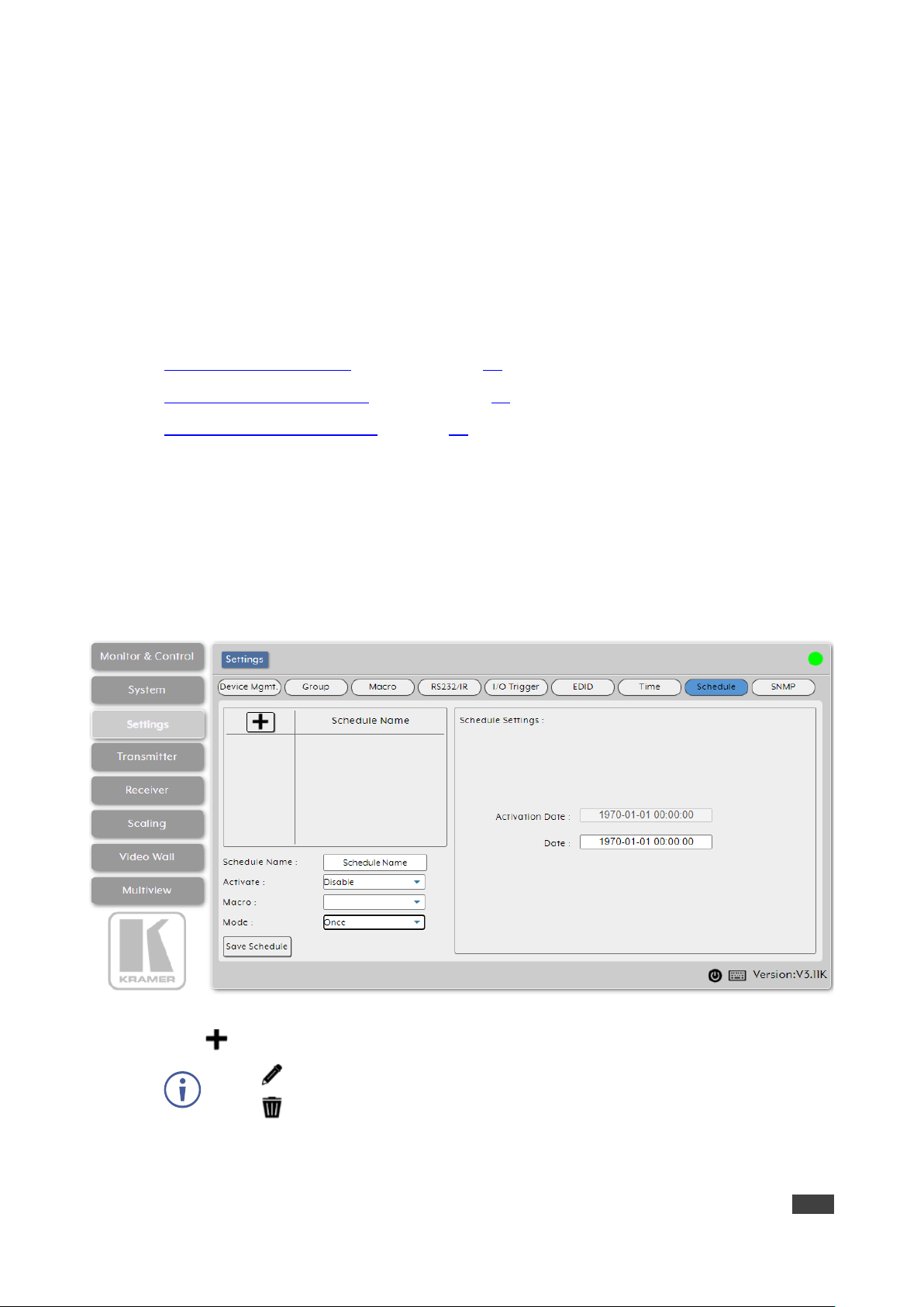
2. Click Schedule. The Schedule page appears.
Figure 28: Settings Tab – Schedule Page
3. Click to create a new schedule.
Click to edit an existing schedule.
Click to delete a schedule
4. Enter Schedule Name.
5. Next to Activate, Enable or Disable the current schedule event.

Kramer Electronics Ltd.
KDS-8-MNGR – Using Embedded Web Pages
41
6. Next to Macro, select the macro (from the drop-down list) to activate at the scheduled
time.
7. Next to Mode, select Once. The Once Scheduling setting appears.
Figure 29: Scheduling – Once Mode
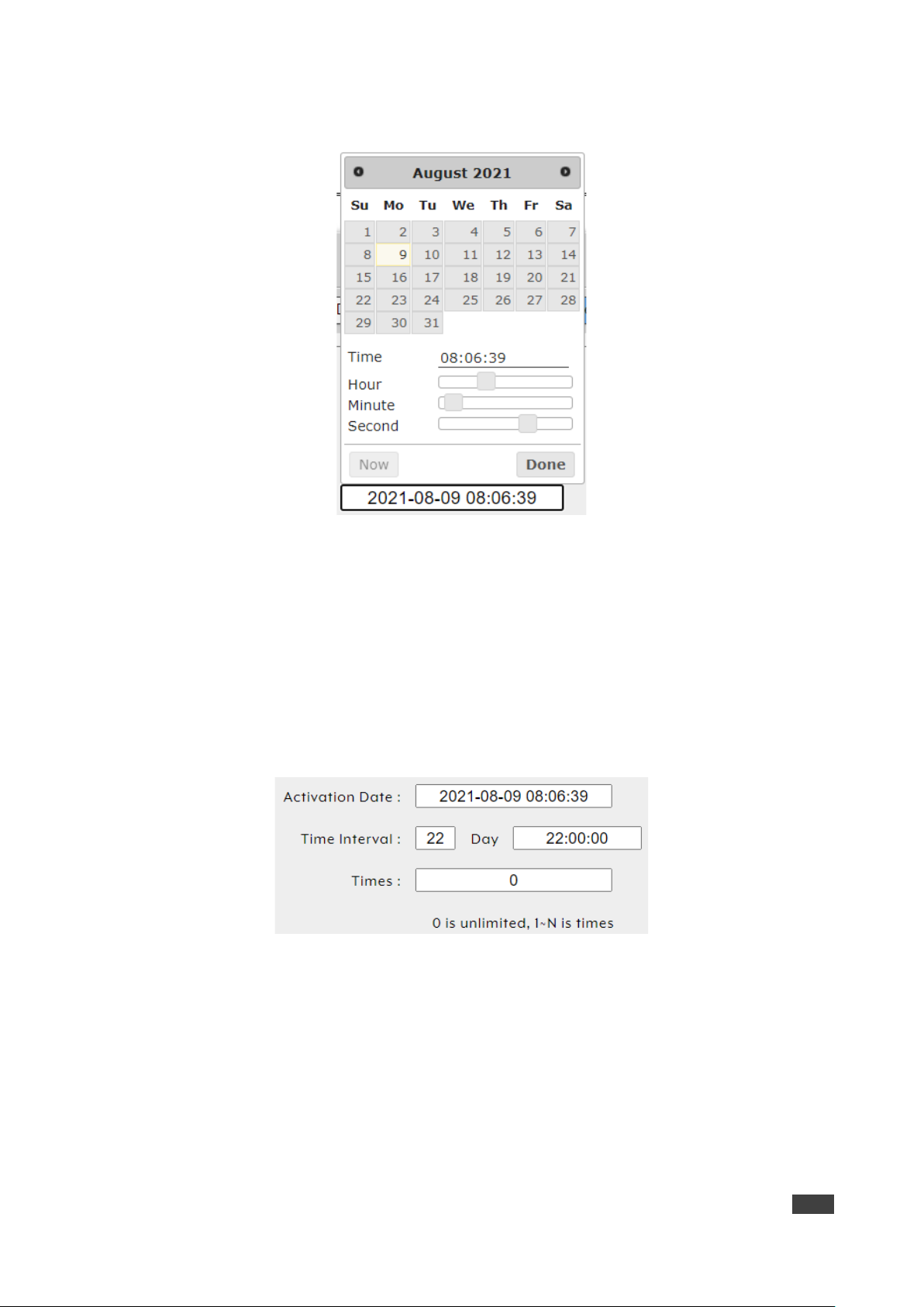
8. Click Date text box for a one-time macro execution. A calendar window opens:
Figure 30: Activate Date – Calendar Window
9. Click Now to change the date and time to the present.
Figure 31: Setting Present Date and Time

Kramer Electronics Ltd.
KDS-8-MNGR – Using Embedded Web Pages
42
10. Select the execution date.
11. Use the sliders to set the execution time.
12. Click Done.
13. Click Save Schedule.
Schedule is set by date to execute a macro once.
Executing a Macro Multiple Times
You can execute a selected macro for a predefined number of times.
To define a schedule by time:
1. In the Menu tabs, select Settings. The Group page appears.
2. Click Schedule. The Schedule page appears.
3. Click to create a new schedule.
Click to edit an existing schedule.
Click to delete a schedule
4. Enter Schedule Name.
5. Next to Activate, enable or disable the current schedule event.
6. Next to Macro, select the macro (from the drop-down list) to activate at the scheduled
time.
7. Next to Mode, select Repeat.
Figure 32: Settings Tab – Schedule Page
Kramer Electronics Ltd.
KDS-8-MNGR – Using Embedded Web Pages
43
8. Click Activate Date box for a one-time macro execution. A calendar window opens:
Figure 33: Activate Date – Calendar Window
Select the execution date.
Use the sliders to set the execution time or click Now to set to the current time.
Click Done.
9. Enter Time Interval text box to set the number of days this schedule is repeated.
10. Click Day text box to set the execution time per day
11. Click Times box to set the number of times this macro will be executed from the set date
and on. Select 0 to have this schedule run repeatedly.
Figure 34: Date – Repeat Scheduling Window
12. Click Save Schedule.
Schedule is set to repeat a set number of times.
Kramer Electronics Ltd.
KDS-8-MNGR – Using Embedded Web Pages
44
Defining a Weekly Schedule
You can execute a selected macro on a weekly schedule.
To define a weekly schedule:
1. In the Menu tabs, select Settings. The Group page appears.
2. Click Schedule. The Schedule page appears.
3. Click to create a new schedule.
Click to edit an existing schedule.
Click to delete a schedule
4. Enter Schedule Name.
5. Next to Activate, enable or disable the current schedule event.
6. Next to Macro, select the macro (from the drop-down list) to activate at the scheduled
time.
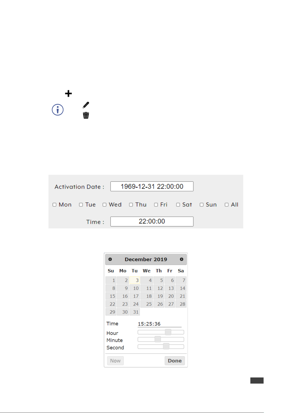
7. Next to Mode, select Weekly. The Week Scheduling setting appears.
Figure 35: Scheduling – Date Mode
8. Click Activate Date box. A calendar window opens:
Figure 36: Activate Date – Calendar Window
Kramer Electronics Ltd.
KDS-8-MNGR – Using Embedded Web Pages
45
9. Select the execution date.
10. Use the sliders to set the execution time or click Now to set to the current time.
11. Click Done.
12. Check the scheduling week days or check All for each day.
13. Set the macro execution time for the selected days.
14. Click Save Schedule.
Schedule is set by week.
Configuring Transmitters
KDS-8-MNGR enables viewing and configuring detected encoder details.
Previously detected encoders that are not currently detected, are identified by a disconnected
icon ( ) and cannot be used for routing.
Transmitter tab enables performing the following actions:
• Viewing and Configuring Encoder Settings on page 45.
• Removing an Encoder on page 47.
Viewing and Configuring Encoder Settings
To view and configure encoder settings:
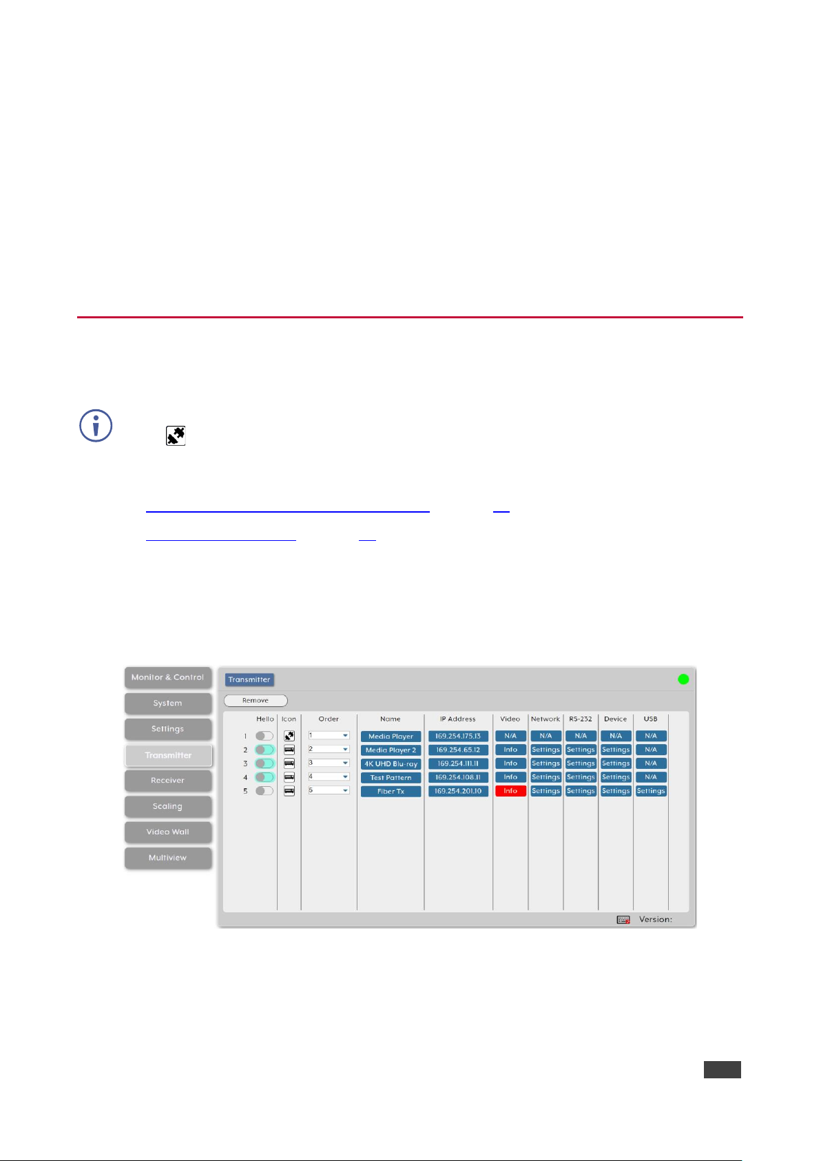
1. In the Menu tabs, select Transmitter. The Transmitter page appears.
Figure 37: Transmitter Page
2. Perform the following actions:
▪ Under Hello, Click a button in the list. The relevant encoder POWER LED flashes to
help you identify that encoder in the system. Click again to return to normal
operation.
Kramer Electronics Ltd.
KDS-8-MNGR – Using Embedded Web Pages
46
Note that not all SDVoE devices support the Hello feature. Hello buttons are
highlighted for devices that support this feature.
▪ Under Icon, view the status of the encoder (connected or disconnected).
If an encoder stream requires more bandwidth than is available, a warning icon
( ) is displayed instead of the normal source icon. The video output from a source
displaying this icon may become visually unstable. We recommend that you lower
the resolution or the framerate of the stream.
▪ Under Order, define the order of the encoders in the list via drop-down box.
Changing the order here also changes the units’ list order in other tabs.
▪ Under Name, view the name of each source encoder device. Change the device
name via Device pop-up window (see below).
▪ Under IP Address, view the encoder IP address.
▪ Under Video, Click Info to view video source information via the pop-up display
window. If no live source is present, Info button appears red.
▪ Under Network, click Settings to view and change Network settings via the Network
pop-up window. Click Save to accept changes and exit window.
▪ Under RS-232, click Settings to view and change RS-232 settings via the RS-232
pop-up window. Click Save to accept changes and exit window.
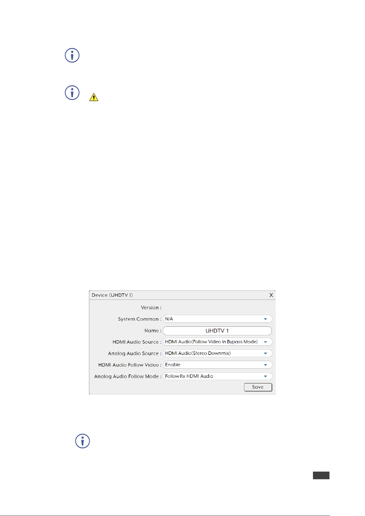
▪ Under Device, click Settings to view and change device settings via the device pop-
up window. Select a System Command to the unit (such as factory reset, Reboot the
unit, firmware update and transform transceiver to receiver), change the device
name, and so on. Click Save to accept changes and exit window.
Figure 38: Transmitter Page – Device Settings
▪ Under USB, click Settings to view and change USB settings via the USB pop-up
window. Click Save to accept changes and exit window.
USB functionality is not supported by all SDVoE units.
Encoder Settings are configured.

Kramer Electronics Ltd.
KDS-8-MNGR – Using Embedded Web Pages
47
Removing an Encoder
Only disconnected encoders can be removed.
To remove an encoder from the list:
1. In the Menu tabs, select Transmitter. The Transmitter page appears.
2. Click Remove. The Remove window appears.
3. Select an encoder from the list.
4. Click Confirm.
The selected encoder is removed from the list.
Configuring Receivers
KDS-8-MNGR enables viewing and configuring detected decoder details.
Previously detected decoders that are not currently detected, are identified by a disconnected
icon ( ) and cannot be used for routing.
Receiver tab enables performing the following actions:
• Viewing and Configuring Decoder Settings on page 47.
• Removing a Decoder on page 49.
Viewing and Configuring Decoder Settings
To view and configure decoder settings:
1. In the Menu tabs, select Receiver. The Receiver page appears.
Figure 39: Receiver Page

Kramer Electronics Ltd.
KDS-8-MNGR – Using Embedded Web Pages
48
2. Perform the following actions:
▪ Under Hello, Click a button in the list. The relevant encoder POWER LED flashes to
help you identify that encoder in the system. Click again to return to normal
operation.
Note that not all SDVoE devices support the Hello feature. Hello buttons are
highlighted for devices that support this feature.
▪ Under Icon, view the current status of the decoder (connected or disconnected).
If a decoder stream requires more bandwidth than is available, a warning icon ( )
is displayed instead of the normal source icon. The video output from a source
displaying this icon may become visually unstable. We recommend that you lower
the resolution or the framerate of the stream.
▪ Under Order, define the order of the encoders in the list via drop-down box.
Changing the order here also changes the units’ list order in other tabs.
▪ Under Name, view the name of each display decoder device. Change the device
name via Device pop-up window (see below).
▪ Under IP Address, view the decoder IP address.
▪ Under Video, Click Info to view video source information via the pop-up display
window. If no live source is present, Info button appears red.
▪ Under Network, click Settings to view and change Network settings via the Network
pop-up window. Click Save to accept changes and exit window.
▪ Under RS-232, click Settings to view and change RS-232 settings via the RS-232
pop-up window. Click Save to accept changes and exit window.
▪ Under Device, click Settings to view and change device settings via the device pop-
up window. Select a System Command to the unit (such as factory reset, Reboot the
unit, firmware update and transform transceiver to receiver), change the device
name, and so on. Click Save to accept changes and exit window.
Figure 40: Receiver Page – Device Settings

Kramer Electronics Ltd.
KDS-8-MNGR – Using Embedded Web Pages
49
▪ Under USB, click Settings to view and change USB settings via the USB pop-up
window. Click Save to accept changes and exit window.
USB functionality is not supported by all SDVoE units.
Decoder Settings are configured.
Removing a Decoder
Only disconnected decoders can be removed.
To remove an encoder from the list:
1. In the Menu tabs, select Receiver. The Receiver page appears.
2. Click Remove. The Remove window appears.
3. Select a decoder from the list.
4. Click Confirm.
The selected encoder is removed from the list.
Defining Output Resolution
Set detected decoder output resolution via drag-and-drop control.
Since scaling applies only to the decoder side, a change in the resolution does not affect
bandwidth usage.
To define the output resolution:
1. In the Menu tabs, select Scaling. The Scaling page appears.
Figure 41: Scaling Page
Kramer Electronics Ltd.
KDS-8-MNGR – Using Embedded Web Pages
50
2. Click and drag a decoder/group of decoders/all decoders (Rx All) from the Receiver area
to a resolution button in the Resolution area.
Selecting “Bypass” forces that decoder to output all routed sources in their native resolutions.
You can also drag and drop resolutions onto decoders to change their output resolution.
Output resolution is set.
Configuring Video Walls
Configure or modify video walls of up to 8x8 using multiple decoders in a group.
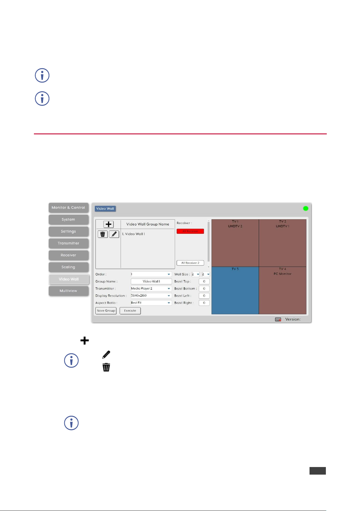
To configure a video wall:
1. In the Menu tabs, select Video Wall. The Video Wall page appears.
Figure 42: Video Wall Page
2. Click to create a new Video Wall group.
Click to edit an existing video wall group.
Click to delete a group
3. Enter group details:
▪ Next to Order, open the drop-down box to select the video wall group order (also use
to change the order of existing groups).
Video wall groups are displayed in the Monitor & Control tab in the same order.
▪ Enter Group Name.
▪ Select the encoder to use as the video source for the video wall.

Kramer Electronics Ltd.
KDS-8-MNGR – Using Embedded Web Pages
51
▪ Select the output resolution for all decoders in the video wall to output to their
connected displays.
▪ Select the Aspect Ratio to use when presenting a source across the video wall.
Selecting Best Fit maintains the aspect ratio of the original source while filling the
video wall as much as possible and adding black bars where necessary.
Selecting Full Screen stretches the source to fit the video wall, regardless of the
original source’s aspect ratio.
▪ Select the video wall size rows x columns up to 8x8 (64 devices).
▪ Set the Bezel Top/Bottom/Left/Right size in pixels.
We recommend that you use the same make and model for all displays within a
video wall to avoid bezel and panel size discrepancies.
4. Under Receiver, which lists all the available decoders, drag and drop each decoder to its
correct position within the video wall grid to the right of the list.
the name of the decoder is displayed within the selected location of the video wall and
the display changes colors:
▪ Green – the display is assigned to the video wall and is in video wall mode.
▪ Red – the display is assigned but is not active/ in the correct mode.
▪ Blue – no display has been assigned yet.
5. Click Save Group to save the changes to the current video wall configuration.
6. Click Execute to save the changes to the current video wall configuration and then
execute the changes. If the video wall is not already active, this action activates it.
Video wall is configured.
Configuring Multiviews
Configure or modify the multiviewer functionality for each decoder.
When displaying an encoder source in a multiviewer window, the bandwidth on that encoder
should usually be increased, depending on the pixel size of the window on the multiviewer
and the frame rate of the input source.
When using 4K sources, we recommend that you enable the “Multiview Divide FPS by two”
feature on the encoder.

Kramer Electronics Ltd.
KDS-8-MNGR – Using Embedded Web Pages
52
To configure multiview features:
1. In the Menu tabs, select Multiview. The Multiview page appears.
Figure 43: Multiview Page
2. Click to create a new Multiview preset.
Click to edit an existing Multiview preset.
Click to delete a preset
Deleting a Multiview preset that is currently active, does not disable the Multiview
output. To remove a multiview output, route a new source to that output or disable
the output from the Monitor & Control tab (see Monitoring and Controlling Decoders
and Encoders on page 14).
3. Enter Preset details:
▪ Next to Order, open the drop-down box to select the Multiview preset order (also use
to change the order of existing groups).
Multiview presets are displayed in other tabs in the same order.
▪ Enter Multiview Preset Name.
▪ Select the decoder display to output Multiview preset.
▪ Select the resolution for the decoder Multiview output.
▪ Select the Aspect Ratio to use when presenting the sources in the Multiview
windows. Selecting Best Fit maintains the aspect ratio of the original source while
filling the video wall as much as possible and adding black bars where necessary.
Selecting Full Screen stretches the source to fit the video wall, regardless of the
original source’s aspect ratio.
This setting applies to all sources/windows within the current Multiview preset.

Kramer Electronics Ltd.
KDS-8-MNGR – Using Embedded Web Pages
53
▪ Scroll through the various predefined Multiview layouts to select the required
configuration (windows location and number) for the Multiview window.
Customized layouts are not currently supported.
▪ Set the Bezel Top/Bottom/Left/Right size in pixels.
We recommend that you use the same make and model for all displays within a
video wall to avoid bezel and panel size discrepancies.
4. Under Receiver, which lists all the available decoders, drag and drop each decoder to its
correct position within the video wall grid to the right of the list.
the name of the decoder is displayed within the selected location of the video wall and
the display changes colors:
▪ Green – the display is assigned to the video wall and is in video wall mode.
▪ Red – the display is assigned but is not active/ in the correct mode.
▪ Blue – no display has been assigned yet.
5. Click Save Group to save the changes to the current video wall configuration.
6. Click Execute to save the changes to the current video wall configuration and then
execute the changes. If the video wall is not already active, this action activates it.
Video wall is configured.

Kramer Electronics Ltd.
KDS-8-MNGR – Technical Specifications
54
Technical Specifications
Output
1 HDMI
On a female HDMI connector
Control Ports
1 RS-232
On a 3-pin terminal block
8 Triggers
On a 10-pin terminal block connector
2 LAN
On RJ-45 female connectors
1 USB 2.0
On a Type A USB connector
Video
Output Resolution
1920×1080@60Hz
Compliance
HDCP 1.4, HDCP 2.2
Indication LED
Front Panel
Power LED
Power
Consumption
5V DC, 1.4A
Source
5V DC, 4A
Environmental
Conditions
Operating Temperature
0° to +40°C (32° to 104°F)
Storage Temperature
-20° to +60°C (-4° to 140°F)
Humidity
20% to 90%, RHL non-condensing
Regulatory
Compliance
Safety
CE, FCC
Environmental
RoHs, WEEE
ESD Protection (HBM)
±8kV (Air Discharge)
±4kV (Contact Discharge)
Enclosure
Size
Special
Type
Metal (steel)
Cooling
Convection Ventilation
General
Net Dimensions (W, D, H)
23.1cm x 10.8cm x 2.5cm
(9.1" x 4.2" x 1")
Shipping Dimensions (W, D, H)
38.2cm x 18.8cm x 6cm
(15" x 7.4" x 2.4")
Net Weight
0.65kg (1.4lbs) approx.
Shipping Weight
1.15kg (2.5lbs) approx.
Accessories
Included
Power adapter and cord
Specifications are subject to change without notice at www.kramerav.com

Kramer Electronics Ltd.
KDS-8-MNGR – Technical Specifications
55
Default Communication Parameters
RS-232
Baud Rate:
19,200
Data Bits:
8
Stop Bits:
1
Parity:
None
IP
LAN1
DHCP
LAN2 IP Address:
192.168.1.50
Subnet Mask:
255.255.255.0
Gateway:
192.168.1.254
User/Password:
Admin/Admin
Full Factory Reset
Web pages
In SYSTEM page select reset options: Factory reset; reset all transmitters;
reset all receivers.
Video Specifications
Supported Resolutions (Hz)
Output
HDMI
720×400p@70/85
640×480p@60/72/75/85
720×480i@60
720×480p@60
720×576i@50
720×576p@50
800×600p@56/60/72/75/85
848×480p@60
1024×768p@60/70/75/85
1152×864p@75
1280×720p@50/60
1280×768p@60/75/85
1280×800p@60/75/85
1280×960p@60/85
1280×1024p@60/75/85
1360×768p@60
1366×768p@60
1400×1050p@60
1440×900p@60/75
1600×900p@60RB
1600×1200p@60
1680×1050p@60
1920×1080i@50/60
1920×1080p@24/25/30
1920×1080p@50/60
60
1920×1200p@60RB

Kramer Electronics Ltd.
KDS-8-MNGR – Technical Specifications
56
Cable Length
1080p
4K30
4K60
8-bit
12-bit
(4:4:4) 8-bit
(4:4:4) 8-bit
High Speed HDMI Cable
HDMI Output
15m
Bandwidth Category Examples:
• 1080p (FHD Video)
▪ Up to 1080p@60Hz, 12-bit color
▪ Data rates lower than 5.3Gbps or below 225MHz TMDS clock
• 4K30 (4K UHD Video)
▪ 4K@24/25/30Hz & 4K@50/60Hz (4:2:0), 8-bit color
▪ Data rates higher than 5.3Gbps or above 225MHz TMDS clock but below 10.2Gbps
• 4K60 (4K UHD+ Video)
▪ 4K@50/60Hz (4:4:4, 8-bit)
▪ 4K@50/60Hz (4:2:0, 10-bit HDR) Data rates higher than 10.2Gbp

Kramer Electronics Ltd.
KDS-8-MNGR – Acronyms
57
Acronyms
ACRONYM
COMPLETE TERM
10GbE
10 Gigabit Ethernet
ADC
Analog-to-Digital Converter
ASCII
American Standard Code for Information Interchange
AVoIP
Audio/Video over IP
AVR
Audio/Video Receiver or Recorder
Cat.5e
Enhanced Category 5 cable
Cat.6
Category 6 cable
Cat.6A
Augmented Category 6 cable
Cat.7
Category 7 cable
CLI
Command-Line Interface
DAC
Digital-to-Analog Converter
DHCP
Dynamic Host Configuration Protocol
DP
DisplayPort
EDID
Extended Display Identification Data
GbE
Gigabit Ethernet
GUI
Graphical User Interface
HDCP
High-bandwidth Digital Content Protection
HDMI
High-Definition Multimedia Interface
HDR
High Dynamic Range
HDTV
High-Definition Television
IGMP
Internet Group Management Protocol
IP
Internet Protocol
IR
Infrared
KVM
Keyboard/Video/Mouse
LAN
Local Area Network
LED
Light-Emitting Diode
LPCM
Linear Pulse-Code Modulation
MAC
Media Access Control
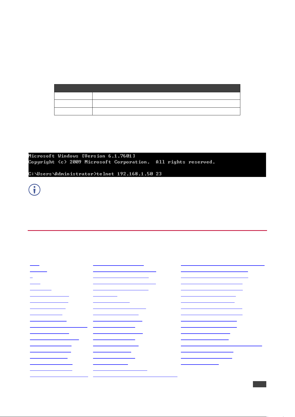
Kramer Electronics Ltd.
KDS-8-MNGR – Telnet Control
58
Telnet Control
Before attempting to use Telnet control, please ensure that both the unit and the PC are
connected to the same active networks.
To Access the Command Line Interface (CLI)
Windows 7
Click Start, type “cmd” in the search field, and press Enter.
Windows XP
Click Start > Run, type “cmd”, and press Enter.
Mac OS X
Click Go > Applications > Utilities > Terminal.
Once in the Command Line Interface (CLI) type “telnet” followed by the IP address of the unit
(and the port number if it is non-standard) and then hit “Enter”. This will connect us to the unit
we wish to control.
If the IP address is changed then the IP address required for Telnet access will also change
accordingly.
This unit defaults to DHCP mode. The current IP address can be verified using the HDMI
output or RS-232 if the Device Discovery software is not available.
RS-232 and Telnet Commands
The RS-232 contains the following Telnet commands:
help
help N1
?
? N1
get fw ver
set factory default
get command ver
get model name
get model type
get mac N1 addr
set factory ipconfig default
set system reboot
set lan N1 ip mode N2
get lan N1 ip mode
get lan N1 ipconfig
get lan N1 ipaddr
get lan N1 netmask
get lan N1 gateway
set lan N1 static ipaddr N2
get lan N1 static ipaddr
set lan N1 static netmask N2
get lan N1 static netmask
set lan N1 static gateway N2
get lan N1 static gateway
get uart list
set uart N1 reset
set uart N1 baudrate N2
get uart N1 baudrate
set uart N1 stop bit N2
get uart N1 stop bit
set uart N1 data bit N2
get uart N1 data bit
set uart N1 parity N2
get uart N1 parity
set uart 2 mode N1
get uart 2 mode
set uart 2 command [N1]
set voip N1 audio out oN2 route N3 n4
set all voip audio out oN1 route N2 N3
set tx N1 uart 1 command [N2]
set rx N1 uart 1 command [N2]
set all tx uart command [N1]
set all rx uart command [N1]
set voip N1 uart route N2
set all voip uart route N1
set tx N1 ir 1 command [N2]
set rx N1 ir 1 command [N2]
set all tx ir command [N1]
set all rx ir command [N1]
set voip N1 ir route N2
set all voip ir route N1
set voip N1 usb device o1 route N2 1
set video wall preset N1
set multiview preset N1
set macro N1 run

Kramer Electronics Ltd.
KDS-8-MNGR – Telnet Control
59
Commands will not be executed unless followed by a carriage return.
Commands are not case-sensitive.
help
help
Show the full command list.
help N1
help N1
Show details about the specified command.
N1 = {Command}
?
?
Show the full command list.
? N1
? N1
Show details about the specified command.
N1 = {Command}
get fw ver
get fw ver
Show the unit’s current firmware version.
set factory default
set factory default
Reset the unit to the factory defaults.
get command ver
get command ver
Show the unit’s current command version.
get model name
get model name
Show the unit’s model name.
get model type
get model type
Show the unit’s product type.

Kramer Electronics Ltd.
KDS-8-MNGR – Telnet Control
60
get mac N1 addr
get mac N1 addr
Show the MAC address of the specified LAN port.
Available values for N1:
1 ....................................... [LAN port 1]
2 ....................................... [LAN port 2]
set factory ipconfig default
set factory ipconfig default
Reset the unit’s network settings to the factory defaults.
set system reboot
set system reboot
Reboot the unit.
set lan N1 ip mode N2
set lan N1 ip mode N2
Set the IP address assignment mode of the specified LAN port.
Available values for N1:
1 ....................................... [LAN Port 1]
2 ....................................... [LAN Port 2]
Available values for N2:
Static ................................ [Static IP mode]
DHCP ............................... [DHCP mode]
get lan N1 ip mode
get lan N1 ip mode
Show the current IP address assignment mode of the specified LAN
port.
Available values for N1:
1 ....................................... [LAN Port 1]
2 ....................................... [LAN Port 2]
get lan N1 ipconfig
get lan N1 ipconfig
Show the specified LAN port’s current IP configuration information.
Available values for N1:
1 ....................................... [LAN Port 1]
2 ....................................... [LAN Port 2]

Kramer Electronics Ltd.
KDS-8-MNGR – Telnet Control
61
get lan N1 ipaddr
get lan N1 ipaddr
Show the specified LAN port’s current IP address.
Available values for N1:
1 ....................................... [LAN Port 1]
2 ....................................... [LAN Port 2]
get lan N1 netmask
get lan N1 netmask
Show the specified LAN port’s current netmask.
Available values for N1:
1 ....................................... [LAN Port 1]
2 ....................................... [LAN Port 2]
get lan N1 gateway
get lan N1 gateway
Show the specified LAN port’s current gateway address.
Available values for N1:
1 ....................................... [LAN Port 1]
2 ....................................... [LAN Port 2]
set lan N1 static ipaddr N2
set lan N1 static ipaddr N2
Set the specified LAN port’s static IP address.
Available values for N1:
1 ....................................... [LAN Port 1]
2 ....................................... [LAN Port 2]
N2 = X.X.X.X .................... [X = 0~255, IP address]
get lan N1 static ipaddr
get lan N1 static ipaddr
Show the specified LAN port’s current static IP address.
Available values for N1:
1 ....................................... [LAN Port 1]
2 ....................................... [LAN Port 2]

Kramer Electronics Ltd.
KDS-8-MNGR – Telnet Control
62
set lan N1 static netmask N2
set lan N1 static netmask N2
Set the specified LAN port’s static netmask.
Available values for N1:
1 ....................................... [LAN Port 1]
2 ....................................... [LAN Port 2]
N2 = X.X.X.X .................... [X = 0~255, netmask]
get lan N1 static netmask
get lan N1 static netmask
Show the specified LAN port’s current static netmask.
Available values for N1:
1 ....................................... [LAN Port 1]
2 ....................................... [LAN Port 2]
set lan N1 static gateway N2
set lan N1 static gateway N2
Set the specified LAN port’s static gateway address.
Available values for N1:
1 ....................................... [LAN Port 1]
2 ....................................... [LAN Port 2]
N2 = X.X.X.X .................... [X = 0~255, gateway address]
get lan N1 static gateway
get lan N1 static gateway
Show the specified LAN port’s current static gateway address.
Available values for N1:
1 ....................................... [LAN Port 1]
2 ....................................... [LAN Port 2]
get uart list
get uart list
List all available serial ports.
set uart N1 reset
set uart N1 reset
Reset the specified serial port’s settings to the factory defaults.
Available values for N1:
1 ....................................... [3-pin serial port]
2 ....................................... [5-pin serial port]

Kramer Electronics Ltd.
KDS-8-MNGR – Telnet Control
63
set uart N1 baudrate N2
set uart N1 baudrate N2
Set the baud rate of the specified serial port.
Available values for N1:
1 ....................................... [3-pin serial port]
2 ....................................... [5-pin serial port]
Available values for N2:
2400 ................................. [2400 baud]
4800 ................................. [4800 baud]
9600 ................................. [9600 baud]
19200 ............................... [19200 baud]
38400 ............................... [38400 baud]
57600 ............................... [57600 baud]
115200 ................................. [115200 baud]
get uart N1 baudrate
get uart N1 baudrate
Show the current baud rate of the specified serial port.
Available values for N1:
1 ....................................... [3-pin serial port]
2 ....................................... [5-pin serial port]
set uart N1 stop bit N2
set uart N1 stop bit N2
Set the number of stop bits for the specified serial port.
Available values for N1:
1 ....................................... [3-pin serial port]
2 ....................................... [5-pin serial port]
Available values for N2:
1 ....................................... [1 stop bit]
2 ....................................... [2 stop bits]
get uart N1 stop bit
get uart N1 stop bit
Show the current number of stop bits for the specified serial port.
Available values for N1:
1 ....................................... [3-pin serial port]
2 ....................................... [5-pin serial port]

Kramer Electronics Ltd.
KDS-8-MNGR – Telnet Control
64
set uart N1 data bit N2
set uart N1 data bit N2
Set the data bits used by the specified serial port.
Available values for N1:
1 ....................................... [3-pin serial port]
2 ....................................... [5-pin serial port]
Available values for N2:
7 ....................................... [7 data bits]
8 ....................................... [8 data bits]
get uart N1 data bit
get uart N1 data bit
Show the current number of data bits used by the specified serial port.
Available values for N1:
1 ....................................... [3-pin serial port]
2 ....................................... [5-pin serial port]
set uart N1 parity N2
set uart N1 parity N2
Set the parity of the specified serial port.
Available values for N1:
1 ....................................... [3-pin serial port]
2 ....................................... [5-pin serial port]
Available values for N2:
0 ....................................... [None]
1 ....................................... [Odd]
2 ....................................... [Even]
get uart N1 parity
get uart N1 parity
Show the current parity setting of the specified serial port.
Available values for N1:
1 ....................................... [3-pin serial port]
2 ....................................... [5-pin serial port]
set uart 2 mode N1
set uart 2 mode N1
Set the operational mode of the Control Output (5-pin) serial port. Available values for N1:
0 ....................................... [Disabled]
1 ....................................... [RS-232 mode]
2 ....................................... [RS-422 mode]
3 ....................................... [RS-485 mode]

Kramer Electronics Ltd.
KDS-8-MNGR – Telnet Control
65
get uart 2 mode
get uart 2 mode
Show the current operational mode of the Control Output (5-pin) serial port.
set uart 2 command [N1]
set uart 2 command [N1]
Transmit the specified command data via the Control Output (5-pin)
serial port.
N1 = {Command data} ...... [ASCII text]
Note: To transmit hex data, each ASCII hex pair (octet) must be preceded by “\x”. For
example a carriage return would be “\x0D”.
set voip N1 audio out oN2 route N3 n4
set voip N1 audio out oN2 route N3 n4
Route the specified transmitter’s audio input to the specified receiver’s
audio output.
N1 = rx1~rx128 ................. [Receiver device ID]
Available values for N2:
1 ....................................... [HDMI audio output]
2 ....................................... [Analog audio output]
N3 = tx1~tx128 ................. [Transmitter device ID]
Available values for N4:
1 ....................................... [HDMI audio input]
2 ....................................... [Analog audio input]
Note: The values for N2 and N4 must match.
set all voip audio out oN1 route N2 N3
set all voip audio out oN1 route N2 N3
Route the specified transmitter’s audio input to all receivers’ audio
outputs.
Available values for N1:
1 ....................................... [HDMI audio output]
2 ....................................... [Analog audio output]
N2 = tx1~tx128 ................. [Transmitter device ID]
Available values for N3:
1 ....................................... [HDMI audio input]
2 ....................................... [Analog audio input]
Note: The values for N1 and N3 must match.

Kramer Electronics Ltd.
KDS-8-MNGR – Telnet Control
66
set tx N1 uart 1 command [N2]
set tx N1 uart 1 command [N2]
Transmit the specified command data via the serial port on the specified transmitter.
N1 = 1~128 ....................... [Transmitter device ID]
N2 = {Command data} ...... [ASCII text]
Note: To transmit hex data, each ASCII hex pair (octet) must be preceded by “\x”. For
example a carriage return would be “\x0D”.
set rx N1 uart 1 command [N2]
set rx N1 uart 1 command [N2]
Transmit the specified command data via the serial port on the specified receiver.
N1 = 1~128 ....................... [Receiver device ID]
N2 = {Command data} ...... [ASCII text]
Note: To transmit hex data, each ASCII hex pair (octet) must be preceded by “\x”. For
example a carriage return would be “\x0D”.
set all tx uart command [N1]
set all tx uart command [N1]
Transmit the specified command data via the serial port on all transmitters.
N1 = {Command data} ...... [ASCII text]
Note: To transmit hex data, each ASCII hex pair (octet) must be preceded by “\x”. For
example a carriage return would be “\x0D”.
set all rx uart command [N1]
set all rx uart command [N1]
Transmit the specified command data via the serial port on all receivers.
N1 = {Command data} ...... [ASCII text]
Note: To transmit hex data, each ASCII hex pair (octet) must be preceded by “\x”. For
example a carriage return would be “\x0D”.
set voip N1 uart route N2
set voip N1 uart route N2
Route the specified transmitter or receiver’s serial port Rx pin to the serial port Tx pin on the
specified transmitter or receiver.
Available values for N1:
tx1~tx128 .............................
[Transmitter device ID (Tx pin)]
rx1~rx128 .............................
[Receiver device ID (Tx pin)]
Available values for N2:
tx1~tx128 .............................
[Transmitter device ID (Rx pin)]
rx1~rx128 .............................
[Receiver device ID (Rx pin)]

Kramer Electronics Ltd.
KDS-8-MNGR – Telnet Control
67
set all voip uart route N1
set all voip uart route N1
Route the specified transmitter or receiver’s serial port Rx pin to all AVoIP devices’ serial
port Tx pins.
Available values for N1:
tx1~tx128 .............................
[Transmitter device ID]
rx1~rx128 .............................
[Receiver device ID]
set tx N1 ir 1 command [N2]
set tx N1 ir 1 command [N2]
Transmit the specified IR data via the IR output on the specified transmitter.
N1 = 1~128 ....................... [Transmitter device ID]
N2 = {IR ASCII hex data} .. [Pronto format IR data]
set rx N1 ir 1 command [N2]
set rx N1 ir 1 command [N2]
Transmit the specified IR data via the IR output on the specified receiver.
N1 = 1~128 ....................... [Receiver device ID]
N2 = {IR ASCII hex data} .. [Pronto format IR data]
set all tx ir command [N1]
set all tx ir command [N1]
Transmit the specified IR data via the IR outputs on all transmitters.
N1 = {IR ASCII hex data} .. [Pronto format IR data]
set all rx ir command [N1]
set all rx ir command [N1]
Transmit the specified IR data via the IR outputs on all receivers.
N1 = {IR ASCII hex data} .. [Pronto format IR data]
set voip N1 ir route N2
set voip N1 ir route N2
Route the specified transmitter or receiver’s IR input to the IR output on the specified
transmitter or receiver.
Available values for N1:
tx1~tx128 .............................
[Transmitter device ID (IR output)]
rx1~rx128 .............................
[Receiver device ID (IR output)]
Available values for N2:
tx1~tx128 .............................
[Transmitter device ID (IR input)]
rx1~rx128 .............................
[Receiver device ID (IR input)]

Kramer Electronics Ltd.
KDS-8-MNGR – Telnet Control
68
set all voip ir route N1
set all voip ir route N1
Route the specified transmitter or receiver’s IR input to all AVoIP devices’ IR outputs.
Available values for N1:
tx1~tx128 .............................
[Transmitter device ID (IR input)]
rx1~rx128 .............................
[Receiver device ID (IR input)]
set voip N1 usb device o1 route N2 1
set voip N1 usb device o1 route N2 1
Route the specified AVoIP device’s USB device to the specified AVoIP
device’s USB host.
Available values for N1:
tx1~tx128 .............................
[Transmitter device ID (USB device)]
rx1~rx128 .............................
[Receiver device ID (USB device)]
Available values for N2:
tx1~tx128 .............................
[Transmitter device ID (USB host)]
rx1~rx128 .............................
[Receiver device ID (USB host)]
set video wall preset N1
set video wall preset N1
Execute the specific video wall configuration.
N1 = 1~128 ....................... [Video wall group ID]
set multiview preset N1
set multiview preset N1
Execute the specific multiview preset.
N1 = 1~128 ....................... [Multiview preset ID]
set macro N1 run
set macro N1 run
Execute the specified macro immediately.
N1 = 1~16 ......................... [Macro ID]

The warranty obligations of Kramer Electronics Inc. (“Kramer Electronics”) for this product are limited to the terms set forth below:
What is Covered
This limited warranty covers defects in materials and workmanship in this product.
What is Not Covered
This limited warranty does not cover any damage, deterioration or malfunction resulting from any alteration, modification, improper or unreasonable use or
maintenance, misuse, abuse, accident, neglect, exposure to excess moisture, fire, improper packing and shipping (such claims must be presented to the carrier),
lightning, power surges, or other acts of nature. This limited warranty does not cover any damage, deterioration or malfunction resulting from the installation or
removal of this product from any installation, any unauthorized tampering with this product, any repairs attempted by anyone unauthorized by Kramer Electronics
to make such repairs, or any other cause which does not relate directly to a defect in materials and/or workmanship of this product. This limited warranty does not
cover cartons, equipment enclosures, cables or accessories used in conjunction with this product.
Without limiting any other exclusion herein, Kramer Electronics does not warrant that the product covered hereby, including, without limitation, the technology
and/or integrated circuit(s) included in the product, will not become obsolete or that such items are or will remain compatible with any other product or technology
with which the product may be used.
How Long this Coverage Lasts
The standard limited warranty for Kramer products is seven (7) years from the date of original purchase, with the following exceptions:
1. All Kramer VIA hardware products are covered by a standard three (3) year warranty for the VIA hardware and a standard three (3) year
warranty for firmware and software updates; all Kramer VIA accessories, adapters, tags, and dongles are covered by a standard one (1) year
warranty.
2. Kramer fiber optic cables, adapter-size fiber optic extenders, pluggable optical modules, active cables, cable retractors, ring mounted
adapters, portable power chargers, Kramer speakers, and Kramer touch panels are covered by a standard one (1) year warranty. Kramer
7-inch touch panels purchased on or after April 1st, 2020 are covered by a standard two (2) year warranty.
3. All Kramer Calibre products, all Kramer Minicom digital signage products, all HighSecLabs products, all streaming, and all wireless products
are covered by a standard three (3) year warranty.
4. All Sierra Video MultiViewers are covered by a standard five (5) year warranty.
5. Sierra switchers & control panels are covered by a standard seven (7) year warranty (excluding power supplies and fans that are covered for
three (3) years).
6. K-Touch software is covered by a standard one (1) year warranty for software updates.
7. All Kramer passive cables are covered by a lifetime warranty.
Who is Covered
Only the original purchaser of this product is covered under this limited warranty. This limited warranty is not transferable to subsequent purchasers or owners of
this product.
What Kramer Electronics Will Do
Kramer Electronics will, at its sole option, provide one of the following three remedies to whatever extent it shall deem necessary to satisfy a proper claim under
this limited warranty:
1. Elect to repair or facilitate the repair of any defective parts within a reasonable period of time, free of any charge for the necessary parts and
labor to complete the repair and restore this product to its proper operating condition. Kramer Electronics will also pay the shipping costs
necessary to return this product once the repair is complete.
2. Replace this product with a direct replacement or with a similar product deemed by Kramer Electronics to perform substantially the same
function as the original product. If a direct or similar replacement product is supplied, the original product’s end warranty date remains
unchanged and is transferred to the replacement product.
3. Issue a refund of the original purchase price less depreciation to be determined based on the age of the product at the time remedy is sought
under this limited warranty.
What Kramer Electronics Will Not Do Under This Limited Warranty
If this product is returned to Kramer Electronics or the authorized dealer from which it was purchased or any other party authorized to repair Kramer Electronics
products, this product must be insured during shipment, with the insurance and shipping charges prepaid by you. If this product is returned uninsured, you assume
all risks of loss or damage during shipment. Kramer Electronics will not be responsible for any costs related to the removal or re-installation of this product from or
into any installation. Kramer Electronics will not be responsible for any costs related to any setting up this product, any adjustment of user controls or any
programming required for a specific installation of this product.
How to Obtain a Remedy Under This Limited Warranty
To obtain a remedy under this limited warranty, you must contact either the authorized Kramer Electronics reseller from whom you purchased this product or the
Kramer Electronics office nearest you. For a list of authorized Kramer Electronics resellers and/or Kramer Electronics authorized service providers, visit our web
site at www.kramerav.com or contact the Kramer Electronics office nearest you.
In order to pursue any remedy under this limited warranty, you must possess an original, dated receipt as proof of purchase from an authorized Kramer Electronics
reseller. If this product is returned under this limited warranty, a return authorization number, obtained from Kramer Electronics, will be required (RMA number).
You may also be directed to an authorized reseller or a person authorized by Kramer Electronics to repair the product.
If it is decided that this product should be returned directly to Kramer Electronics, this product should be properly packed, preferably in the original carton, for
shipping. Cartons not bearing a return authorization number will be refused.
Limitation of Liability
THE MAXIMUM LIABILITY OF KRAMER ELECTRONICS UNDER THIS LIMITED WARRANTY SHALL NOT EXCEED THE ACTUAL PURCHASE PRICE PAID
FOR THE PRODUCT. TO THE MAXIMUM EXTENT PERMITTED BY LAW, KRAMER ELECTRONICS IS NOT RESPONSIBLE FOR DIRECT, SPECIAL,
INCIDENTAL OR CONSEQUENTIAL DAMAGES RESULTING FROM ANY BREACH OF WARRANTY OR CONDITION, OR UNDER ANY OTHER LEGAL
THEORY. Some countries, districts or states do not allow the exclusion or limitation of relief, special, incidental, consequential or indirect damages, or the limitation
of liability to specified amounts, so the above limitations or exclusions may not apply to you.
Exclusive Remedy
TO THE MAXIMUM EXTENT PERMITTED BY LAW, THIS LIMITED WARRANTY AND THE REMEDIES SET FORTH ABOVE ARE EXCLUSIVE AND IN LIEU OF
ALL OTHER WARRANTIES, REMEDIES AND CONDITIONS, WHETHER ORAL OR WRITTEN, EXPRESS OR IMPLIED. TO THE MAXIMUM EXTENT
PERMITTED BY LAW, KRAMER ELECTRONICS SPECIFICALLY DISCLAIMS ANY AND ALL IMPLIED WARRANTIES, INCLUDING, WITHOUT LIMITATION,
WARRANTIES OF MERCHANTABILITY AND FITNESS FOR A PARTICULAR PURPOSE. IF KRAMER ELECTRONICS CANNOT LAWFULLY DISCLAIM OR
EXCLUDE IMPLIED WARRANTIES UNDER APPLICABLE LAW, THEN ALL IMPLIED WARRANTIES COVERING THIS PRODUCT, INCLUDING WARRANTIES
OF MERCHANTABILITY AND FITNESS FOR A PARTICULAR PURPOSE, SHALL APPLY TO THIS PRODUCT AS PROVIDED UNDER APPLICABLE LAW.
IF ANY PRODUCT TO WHICH THIS LIMITED WARRANTY APPLIES IS A “CONSUMER PRODUCT” UNDER THE MAGNUSON-MOSS WARRANTY ACT (15
U.S.C.A. §2301, ET SEQ.) OR OTHER APPLICABLE LAW, THE FOREGOING DISCLAIMER OF IMPLIED WARRANTIES SHALL NOT APPLY TO YOU, AND
ALL IMPLIED WARRANTIES ON THIS PRODUCT, INCLUDING WARRANTIES OF MERCHANTABILITY AND FITNESS FOR THE PARTICULAR PURPOSE,
SHALL APPLY AS PROVIDED UNDER APPLICABLE LAW.
Other Conditions
This limited warranty gives you specific legal rights, and you may have other rights which vary from country to country or state to state.
This limited warranty is void if (i) the label bearing the serial number of this product has been removed or defaced, (ii) the product is not distributed by Kramer
Electronics or (iii) this product is not purchased from an authorized Kramer Electronics reseller. If you are unsure whether a reseller is an authorized Kramer
Electronics reseller, visit our web site at www.kramerav.com or contact a Kramer Electronics office from the list at the end of this document.
Your rights under this limited warranty are not diminished if you do not complete and return the product registration form or complete and submit the online product
registration form. Kramer Electronics thanks you for purchasing a Kramer Electronics product. We hope it will give you years of satisfaction.

www.KramerAV.com
info@KramerAV.com
P/N:
2900-301456
Rev:
1
SAFETY WARNING
Disconnect the unit from the power supply before opening and servicing
For the latest information on our products and a list of Kramer distributors, visit our website where
updates to this user manual may be found.
We welcome your questions, comments, and feedback.
The terms HDMI, HDMI High-Definition Multimedia Interface, and the HDMI Logo are trademarks or registered trademarks of HDMI Licensing Administrator, Inc.
All brand names, product names, and trademarks are the property of their respective owners.
 Loading...