

Page 1

PDF provided by Conference Room AV
Kramer KADS-1 Controllable Active Powered Wall Mounted 5.25" Speaker - Pair
Page 2

USER MANUAL
MODELS:
KADS-100 Master Audio Controller
KADS-1 Speaker
KADS-2 Speaker
P/N: 2900-300260 Rev 3
www.kramerAV.com
Page 3

Page 4

Page 5
Page 6

Page 7

KADS-100/KADS-1/KADS-2 – Contents
i
Contents
1 Introduction 1
2 Getting Started 2
2.1 Achieving the Best Performance 2
2.2 Safety Instructions 2
2.3 Recycling Kramer Products 3
3 Overview 4
3.1 Using the IR Transmitter 5
4 Defining the KADS-100, KADS-1 and KADS-2 6
4.1 Defining the KADS-100 Speaker 6
4.2 Defining the KADS-1 or a KADS-2 9
4.3 Defining the KADS-1 or a KADS-2 10
5 Installing in a Rack 11
6 Connecting the KADS-100, KADS-1 and KADS-2 12
6.1 Installing the Ferrite Rings 14
6.2 Connecting a Serial Controller 15
6.3 Wiring the RJ-45 Connectors 15
7 Setting the Speaker ID 16
8 Operating the KADS-100 17
8.1 Operating the KADS-100 Using the Front Panel Buttons 17
8.2 Operating the KADS-100 Using the Menu 21
8.3 Operating the KADS-100 Using the Web Pages 22
8.4 Operating the KADS-1 and KADS-2 Using the Remote Control 35
9 Updating the KADS-1 or KADS-2 Firmware 36
10 Technical Specifications 37
10.1 Default IP Parameters 39
10.2 Default Logon Credentials 39
11 Protocol 3000 40
11.1 Kramer Protocol 3000 Syntax 40
11.2 Kramer Protocol 3000 Commands 43
Figures
Figure 1: KADS-100 Front Panel 7
Figure 2: KADS-100 Rear Panel 8
Figure 3: KADS-1 Rear Panel 9
Figure 4: KADS-2 Rear Panel 10
Figure 5: Connecting the KADS-100, KADS-1 and KADS-2 12
Figure 6: Looping the Cable through the Ferrite Ring 14
Figure 7: TP PINOUT 15
Figure 8: Setting the Rotary Switches 16
Figure 9: Entering Logon Credentials 23
Figure 10: The Default Page 23
Figure 11: The Switching Page 24
Figure 12: Channel Selection Example 26
Figure 13: Analog Input Selection Button 26
Figure 14: USB Input Selection Button 27
Page 8

ii
KADS-100/KADS-1/KADS-2 - Contents
Figure 15: Playlist Window 28
Figure 16: SPDIF Input Selection Button 29
Figure 17: Test Tone Selection Button 29
Figure 18: The Channel Settings Page 30
Figure 19: The Video and Audio Settings Page 31
Figure 20: The Microphone Settings Page 33
Figure 21: The Authentication Page—Security Disabled 34
Figure 22: The Authentication Page—Security Enabled 34
Figure 23: The About Us Page 35
Page 9

KADS-100/KADS-1/KADS-2 – Introduction
1
1 Introduction
Welcome to Kramer Electronics! Since 1981, Kramer Electronics has been
providing a world of unique, creative, and affordable solutions to the vast range of
problems that confront video, audio, presentation, and broadcasting professionals
on a daily basis. In recent years, we have redesigned and upgraded most of our
line, making the best even better!
Our 1,000-plus different models now appear in 14 groups that are clearly defined
by function: GROUP 1: Distribution Amplifiers; GROUP 2: Switchers and Routers;
GROUP 3: Control Systems; GROUP 4: Format/Standards Converters; GROUP 5:
Range Extenders and Repeaters; GROUP 6: Specialty AV Products; GROUP 7:
Scan Converters and Scalers; GROUP 8: Cables and Connectors; GROUP 9:
Room Connectivity; GROUP 10: Accessories and Rack Adapters; GROUP 11:
Sierra Video Products; GROUP 12: Digital Signage; GROUP 13: Audio; and
GROUP 14: Collaboration.
Congratulations on purchasing your Kramer KADS-100 Master Audio Controller,
KADS-1 Speaker and KADS-2 Speaker which are part of the Kramer Audio
Distribution System and are ideal for:
Small to large presentation and multimedia applications
Long-range audio distribution for schools, hospitals, stores, and security
applications
Page 10

2
KADS-100/KADS-1/KADS-2 - Getting Started
Go to http://www.kramerav.com/downloads/KADS-100 to check for up-to-
date user manuals, application programs, and to check if firmware
upgrades are available (where appropriate).
This equipment is to be used only inside a building. It may only be
connected to other equipment that is installed inside a building.
Caution:
There are no operator serviceable parts inside the unit
Warning:
Use only the power cord that is supplied with the unit
Warning:
Do not open the unit. High voltages can cause
electrical shock! Servicing by qualified personnel only
Warning:
Disconnect the power and unplug the unit from the
wall before installing
2 Getting Started
We recommend that you:
Unpack the equipment carefully and save the original box and packaging
materials for possible future shipment
Review the contents of this user manual
2.1 Achieving the Best Performance
To achieve the best performance:
Use only good quality connection cables (we recommend Kramer high-
performance, high-resolution cables) to avoid interference, deterioration in
signal quality due to poor matching, and elevated noise levels (often
associated with low quality cables)
Do not secure the cables in tight bundles or roll the slack into tight coils
Avoid interference from neighboring electrical appliances that may adversely
influence signal quality
Position your KADS-100, KADS-1, and KADS-2 away from moisture,
excessive sunlight and dust
2.2 Safety Instructions
Page 11

KADS-100/KADS-1/KADS-2 – Getting Started
3
2.3 Recycling Kramer Products
The Waste Electrical and Electronic Equipment (WEEE) Directive 2002/96/EC
aims to reduce the amount of WEEE sent for disposal to landfill or incineration by
requiring it to be collected and recycled. To comply with the WEEE Directive,
Kramer Electronics has made arrangements with the European Advanced
Recycling Network (EARN) and will cover any costs of treatment, recycling and
recovery of waste Kramer Electronics branded equipment on arrival at the EARN
facility. For details of Kramer’s recycling arrangements in your particular country
go to our recycling pages at http://www.kramerelectronics.com/support/recycling/.
Page 12

4
KADS-100/KADS-1/KADS-2 - Overview
3 Overview
The KADS-100 is a Master Audio Controller for use with multiple, remote, active
KADS-1 and KADS-2 speakers. It features eight analog audio inputs, an S/PDIF
digital stereo audio input, and a USB connector for mass-storage audio devices.
RS-232 data and commands travel bi-directionally between controller and
speakers, allowing remote status requests and control of up to 99 daisy-chained
KADS-1 and KADS-2 speakers.
The KADS-100 can provide power to support up to eight KADS-1 speakers. By
adding a KADS-2 speaker it provides power to a further eight speakers. This setup
can be extended to control up to 99 speakers.
The KADS-1 is an active speaker with multi-channel, digital audio, RS-232 data,
and power provided over a single cable.
The KADS-2 is similar to the KADS-1 but it also has a power supply to allow
adding more speakers, either by daisy-chaining them or in a tree and branch
configuration.
The KADS-100, KADS-1 and KADS-2 feature:
High resolution audio
Highly flexible layout options
Eight logical audio channels for mapping to physical inputs
Presets for storing commonly used configurations
Power provision to compatible devices
Transmission up to 30m (100ft) between speakers. Total span of 240m
(800ft) for eight KADS-1 speakers without an additional power supply
Remote control using the built-in Web pages (KADS-100)
Standard 1U 19” rack size (KADS-100)
Page 13

KADS-100/KADS-1/KADS-2 – Overview
5
Each speaker can be individually configured:
Using the KADS-100
Locally using the supplied IR remote controller
3.1 Using the IR Transmitter
You can use the IR remote control transmitter provided to control the KADS-1 and
KADS-2 machine via the built-in IR receiver on the front panel, (see Section 8.4).
Page 14

6
KADS-100/KADS-1/KADS-2 - Defining the KADS-100, KADS-1 and KADS-2
4 Defining the KADS-100, KADS-1 and KADS-2
This section defines the:
KADS-100 Master Audio Controller (see Section 4.1)
KADS-1 Speaker (see Section 4.2 )
KADS-2 Speaker (see Section 4.3)
The KADS-100 has a single output that can be connected to either a KADS-1 or a
KADS-2 up to 30m away.
The KADS-1 has a single output which can be connected to either another
KADS-1 or a KADS-2 up to 30m away with a total of eight speakers in the chain.
The KADS-2 has two outputs that can be connected to either a KADS-1 or a
KADS-2 up to 30m away with a total of eight speakers in the chain. The KADS-2
also has a power input for extending a further eight speakers in the chain.
4.1 Defining the KADS-100 Speaker
Figure 3 defines the front panel of the KADS-100.
Page 15

#
Feature
Function
1
POWER LED
Lights green when the device is powered on
2
KEYPAD 1 ~ 9 and 0
Buttons
Press to select an input or to select which speaker to control depending on the context of the
menu, (see Section 8.2). During setup, the buttons are used for entering numeric values
3
SOUND
CONTROL
Buttons
BASS
Press to select control of the audio bass of the last speaker configured using the menu
4
VOLUME
Press to select control of the audio volume of the last speaker configured using the menu
5
MID
Press to select control of the audio midrange of the last speaker configured using the menu
6
TREBLE
Press to select control of the audio treble using the menu
7
SETUP
Buttons
SPEAKER
Press to select which speaker to control, (see Section 8.2)
8
MIC
Press to select control of the microphone parameters using the menu
9
CHANNEL
Press to select a channel using the Adjust knob after selecting a channel to control
10
ADJUST Rotary Knob
Rotate to move up or down through a menu, or to adjust the parameter of the selected function,
depending on the context of the menu
11
ENTER Button
Press to enter the menu or selected sub-menu, or to accept the displayed parameter.
If you are not in the menu, pressing Enter displays all available menus, (File Playback, Setup,
Speaker Setup, Microphone Setup, and Channel Setup)
12
LCD Display
Displays the configuration menu
13
STO Button
Press to store the current setup
14
RCL Button
Press to recall a stored setup
15
LOCK Button
Press and hold to lock the front panel controls. Press and hold again to unlock
Defining the KADS-100, KADS-1 and KADS-2
7
Figure 1: KADS-100 Front Panel
Page 16

#
Feature
Function
16
MIC 6.5mm Phone Jack
Microphone socket
17
ESC Button
Press to exit one level of the menu
#
Feature
Function
1
AUDIO
INPUTS
IN 1 ~ 8 RCA Connectors
Connect up to eight audio sources
2
S/PDIF RCA Connector
Connect to a digital audio source
3
MIC
DYN COND Switch
Push switch up to select a dynamic type microphone. Push switch down to select a condenser
type microphone, (enables 48V phantom power for the MIC input)
4
To SPEAKERS 2-pin Connector (M)
Connect to the first speaker in the chain, (see Section 6)
5
RS-232 9-pin D-sub Connector (F)
Connect to the remote serial controller to control the KADS-1 or to a PC to upgrade the
firmware
6
PROG/UPGRADE USB Mini USB
Connector
Connect to a PC to perform a firmware upgrade
7
USB Connector
Connect a USB mass storage device, (for example, a USB flash-drive) to provide audio files
8
ETHERNET RJ-45 Connector
Connect to a PC via a LAN for remote control over Ethernet
9
Mains plug, fuse and switch
Connect to the mains supply
8
Defining the KADS-100, KADS-1 and KADS-2
Figure 3 defines the rear panel of the KADS-100.
Figure 2: KADS-100 Rear Panel
Page 17

KADS-100/KADS-1/KADS-2 - Defining the KADS-100, KADS-1 and KADS-2
9
9
#
Feature
Function
1
SPEAKERS
CHAIN
IN 2-Pin
Connector
Connect to the + and – speaker output of a KADS-1,
KADS-2 or KADS-100, (see Section 6)
2
OUT 2-Pin
Connector
Connect to the + and – speaker input of another
KADS-1 or KADS-2
3
LAST Switch
Push to the right when this speaker is the last in the chain,
push to the left when there are additional speakers
connected to OUT
4
LINK LED
Lights green when the device is connected to a source
5
RS-232 3-pin Terminal Block
For the use of Kramer service personnel only
6
USB (Program) Connector
Connect a USB flash-drive to perform a firmware upgrade,
(see Section 9)
7
SPEAKER ID 10 Position
Rotary Switches
Sets the tens and units of the device ID, (see Section 7)
Note: ID 0 is reserved for system use
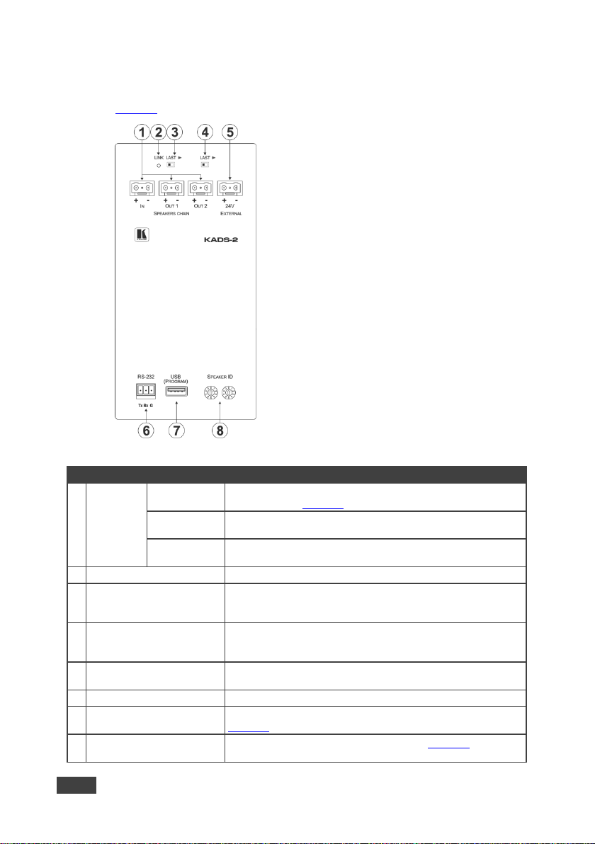
4.2 Defining the KADS-1 or a KADS-2
Figure 3 defines the rear panel of the KADS-1.
Figure 3: KADS-1 Rear Panel
Page 18
10
KADS-100/KADS-1/KADS-2 - Defining the KADS-100, KADS-1 and KADS-2
#
Feature
Function
1
SPEAKERS
CHAIN
IN 2-Pin
Connector
Connect to the + and – speaker output of a KADS-1, KADS-2 or
KADS-100, (see Section 6)
OUT 1 2-Pin
Connector
Connect to the + and – speaker input of another KADS-1 or
KADS-2
OUT 2 2-Pin
Connector
Connect to the + and – speaker input of another KADS-1 or
KADS-2
2
LINK LED
Lights green when the device is connected to a source
3
LAST Out 1 Switch
Push to the right when there are no speakers connected to OUT 1;
push to the left when there are additional speakers connected to
OUT 1
4
LAST Out 2 Switch
Push to the right when there are no speakers connected to OUT 2;
push to the left when there are additional speakers connected to
OUT 2
5
24V EXTERNAL 2-Pin
Connector
Connect to the supplied power adapter when connecting more
than eight devices
6
RS-232 3-pin Terminal Block
For the use of Kramer service personnel only
7
USB (Program) USB
Connector
Connect a USB flash-drive to perform a firmware upgrade, (see
Section 9)
8
SPEAKER ID 10 Position
Rotary Switches
Sets the tens and units of the device ID, (see Section 7).
Note: ID 00 is reserved for system use
4.3 Defining the KADS-1 or a KADS-2
Figure 4 defines the rear panel of the KADS-2.
Figure 4: KADS-2 Rear Panel
Page 19

KADS-100/KADS-1/KADS-2 - Installing in a Rack
11
11
5 Installing in a Rack
This section provides instructions for rack mounting the KADS-100.
Page 20

12
KADS-100/KADS-1/KADS-2 - Connecting the KADS-100, KADS-1 and KADS-2
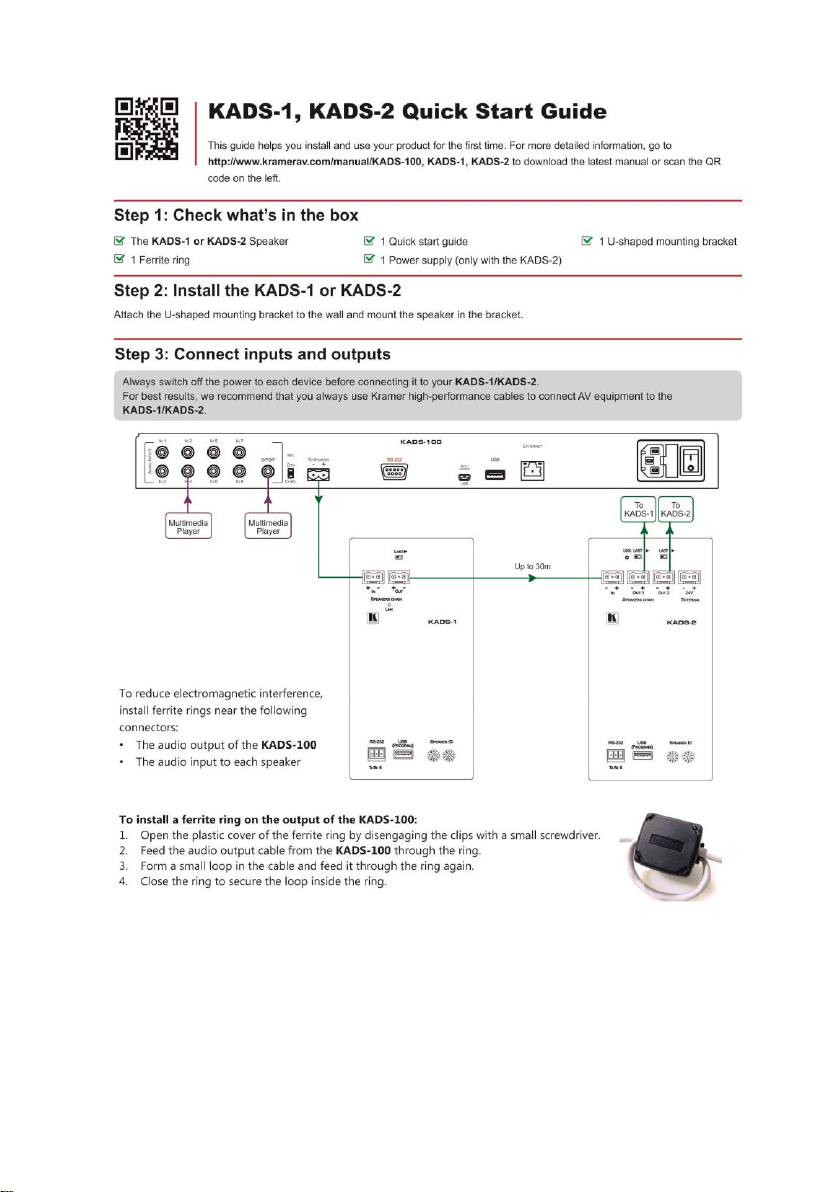
Always switch off the power to each device before connecting it to
your KADS-100, KADS-1 and KADS-2. After connecting your
KADS-100/KADS-1/KADS-2, connect the power to each of them
and then switch on the power to each device.
You do not have to connect all the inputs and outputs, connect only
those that are required.
6 Connecting the KADS-100, KADS-1 and KADS-2
Figure 5: Connecting the KADS-100, KADS-1 and KADS-2
Page 21

KADS-100/KADS-1/KADS-2 - Connecting the KADS-100, KADS-1 and KADS-2
13
13
To connect the KADS-1 and the KADS-2 as illustrated in Figure 5:
In the first chain:
1. Connect the KADS-100 to the SPEAKERS CHAIN IN connector on the first
KADS-1.
2. Connect the SPEAKERS CHAIN OUT connector on the first KADS-100 to
the SPEAKERS CHAIN IN connector on the first KADS-2.
3. Connect the SPEAKERS CHAIN OUT connector on the first KADS-2 to the
SPEAKERS CHAIN IN connector on the second KADS-2.
4. Repeat Step 3 for up to another six KADS-2 speakers until the chain
extends over no more than 240m (787ft).
In the second chain:
5. Connect the SPEAKERS CHAIN OUT connector on the eighth KADS-1 to
the SPEAKERS CHAIN IN connector on the first KADS-2 in the second
chain.
6. Connect the supplied power adapter to the first KADS-2 in the second chain.
7. Connect the first SPEAKERS CHAIN OUT connector on the first KADS-2 in
the second chain to the SPEAKERS CHAIN IN connector on the second
KADS-2 in the second chain.
8. Connect the second SPEAKERS CHAIN OUT connector on the first
KADS-2 in the second chain to the SPEAKERS CHAIN IN connector on the
first KADS-1 speaker in the second chain.
Note: To reduce electromagnetic interference, install ferrite rings near the
following connectors:
The audio output of the KADS-100
The audio input to every speaker
Page 22

14
KADS-100/KADS-1/KADS-2 - Connecting the KADS-100, KADS-1 and KADS-2
6.1 Installing the Ferrite Rings
Figure 6: Looping the Cable through the Ferrite Ring
To install a ferrite ring on the output of the KADS-100:
1. Open the plastic cover of the ferrite ring by disengaging the clips with a
small screwdriver.
2. Feed the audio output cable from the KADS-100 through the ring.
3. Form a small loop in the cable and feed it through the ring again.
4. Close the ring to secure the loop inside the ring.
To install a ferrite ring on the input to each speaker:
1. Open the plastic cover of the ferrite ring by disengaging the clips with a
small screwdriver.
2. Feed the audio input cable to the KADS-1/KADS-2 through the ring.
3. Form a small loop in the cable and feed it through the ring again.
4. Form a second small loop in the cable and feed it through the ring again.
5. Close the ring to secure the loops inside the ring.
Page 23

KADS-100/KADS-1/KADS-2 - Connecting the KADS-100, KADS-1 and KADS-2
15
15
EIA /TIA 568B
Figure 7: TP PINOUT
PIN
Wire Color
1
Orange / White
2
Orange
3
Green / White
4
Blue
5
Blue / White
6
Green
7
Brown / White
8
Brown
6.2 Connecting a Serial Controller
You can connect a serial controller to the KADS-100 via an RS-232 connection
using, for example, a PC.
To connect to the KADS-100 via RS-232:
Connect the RS-232 9-pin D-sub connector on the KADS-100 (only pin 2, pin 3,
and pin 5 need be connected) to the RS-232 9-pin D-sub port on your PC
6.3 Wiring the RJ-45 Connectors
This section defines the TP pinout, using a straight pin-to-pin cable with RJ-45
connectors.
Page 24

16
KADS-100/KADS-1/KADS-2 - Setting the Speaker ID
7 Setting the Speaker ID
Each speaker must have a unique ID, including those in installations with more
than eight speakers. You can set the ID of the speaker (between 01 and 99) using
the rotary switches on the rear panel of the speaker.
Note: ID 00 is reserved for system use and if used may cause the system to
malfunction.
Figure 8: Setting the Rotary Switches
To set the ID of a KADS-1 or KADS-2, (for example, 28 as shown in Figure 8):
1. Turn the KADS-100 off.
2. Using a small screwdriver, turn the left hand rotary switch to the required
number of tens; in this example, 2.
3. Turn the right hand rotary switch to the required number of units; in this
example, 8.
4. Turn the KADS-100 on.
Page 25

KADS-100/KADS-1/KADS-2 - Operating the KADS-100
17
17
8 Operating the KADS-100
The KADS-100 can be operated using either the front panel buttons (which are
shortcuts to the speaker setup menu of the last configured speaker) or the menu.
On power up, the KADS-100 scans for all connected speakers. This can take up
to 60 seconds.
Each of the eight analog inputs is mapped to one of the eight logical, audio
channels. The S/PDIF, microphone, and USB inputs can be mapped to one or
more of the eight logical, audio channels. Each of the eight logical, audio channels
can be mapped to one or more of the speakers.
8.1 Operating the KADS-100 Using the Front Panel Buttons
8.1.1 Setting up a Channel
When switching a channel to S/PDIF or an mp3 source that is defined as stereo,
the paired channel also switches to this source. Paired channels are:
1 and 2
3 and 4
5 and 6
7 and 8
Examples:
1. The mp3 source is selected as stereo, then:
If channel 1 is switched to mp3, channel 2 automatically switches as well
If channel 4 is switched to mp3, channel 3 automatically switches as well
2. The mp3 source is selected as mono, then:
If channel 1 is switched to mp3, channel 2 does not switch
If channel 4 is switched to mp3, channel 3 does not switch
Page 26

18
KADS-100/KADS-1/KADS-2 - Operating the KADS-100
To set up a channel:
1. Press Enter.
The display shows the first entry of the menu.
2. Use the rotary knob to move down the menu to Channel Setup.
3. Press Enter.
The display shows the Channel ID selection.
4. Use the rotary knob to move up or down the channel list. Press Enter when
the required channel ID is displayed.
The Channel properties menu is displayed.
5. Press Enter or use the rotary knob to move up and down the channel
properties. Repeat until the required properties have been set.
6. Press Esc repeatedly until you exit the menu system.
8.1.2 Selecting a Speaker to Control
Note: If no speaker is selected, then the last speaker that was selected is
controlled. If no speaker was previously selected then speaker 1 is controlled by
default.
To select a speaker to control, use either of the following methods:
1. Press the required Keypad button on the front panel.
The selected Speaker button lights red and the LED on the speaker lights.
2. Enter the number of the speaker to control using the Keypad 1 to 9 and 0
buttons, for example, press 2 and 8 for speaker 28.
The selected speaker number is displayed on the LCD.
3. Press the Enter button.
Use the menu options to configure the speaker, (see Section 8.2).
—OR—
1. Press Enter.
Page 27

KADS-100/KADS-1/KADS-2 - Operating the KADS-100
19
19
2. Select Speaker Setup using the rotary knob.
3. Press Enter.
The selected Speaker button lights red and the LED on the speaker lights.
4. Enter the number of the speaker to control using the Keypad 1 to 9 and 0
buttons, for example, press 2 and 8 for speaker 28. The selected speaker
number is displayed on the LCD.
5. Press the Enter button.
Use the menu options to configure the speaker, (see Section 8.2).
8.1.3 Setting the Microphone Gain and Delay
To set the microphone gain and delay:
1. Press the Mic button on the front panel.
The Mic button lights red.
2. Use the menu options to set the microphone gain and delay, (see
Section 8.2).
8.1.4 Setting the Volume, Bass, Mid, and Treble Audio Properties
Note: The following procedure sets the audio properties for the speaker that was
last selected unless another speaker is first selected, (see Section 8.1.2). If no
speaker has been selected yet, the procedure will set the audio properties for
speaker 1.
To set the audio properties:
1. Press either the Volume, Mid, Bass, or Treble button on the front panel.
The selected button lights red and the current level for the selected audio
property is displayed on the LCD.
2. Use the menu options to set the level for the selected audio property, (see
Section 8.2).
Page 28

20
KADS-100/KADS-1/KADS-2 - Operating the KADS-100
8.1.5 Storing and Recalling Configurations
To store a configuration in a preset:
1. Press the STO button.
The button lights red.
2. Press and hold (until the STO button no longer lights) one of the numbered
Keypad buttons in which to store the current configuration.
To restore a configuration from a preset:
1. Press the RCL button from which to recall the configuration.
The button lights red.
2. Press and hold (until the RCL button no longer lights) the numbered Keypad
button from which to recall the configuration.
A progress message is displayed indicating which speaker is being updated.
To lock and unlock the front panel buttons:
1. Press and hold the Lock button.
The panel buttons are locked and the Lock button lights. Pressing any
button now causes the Lock button to flash for a few seconds.
2. Press and hold the Lock button.
The panel buttons are unlocked and the Lock button no longer lights.
8.1.6 Resetting the KADS-100 to Factory Default Parameters
To reset the KADS-100 to factory default parameters:
1. Turn off the device.
2. Press and hold the Enter and Esc buttons together.
3. While holding the buttons depressed, turn on the device and wait a few
seconds.
The device is reset to factory default.
Page 29

KADS-100/KADS-1/KADS-2 - Operating the KADS-100
21
21
Menu Item
Level One
Level Two
Level Three
File Playback
Setup
Play/Pause
Stop
Previous
Next
Speaker Setup
Speaker ID [01-99]:
Speaker Channel
1 to 8
Speaker Volume (db)
–76 to +24
Speaker Bass (db)
–20 to +20
Speaker Mid (db)
–20 to +20
Speaker Treble (db)
–20 to +20
Mic Setup
Mic Gain (db)
–16 to +16
Mic Delay (ms)
1 to 85
8.2 Operating the KADS-100 Using the Menu
You can use the menu to configure both the KADS-100 and all of the speakers.
After 5 minutes of inactivity, the KADS-100 automatically exits the menu.
Note: This is the only way to access the File Playback menu option.
To use the menu:
1. Press the Menu button.
The menu options appear on the display.
2. Use the Adjust rotary knob to move up or down through the options until you
reach the required item, (see the table below). Turn the knob clockwise to
move down the list or turn the knob anti-clockwise to move up the list.
3. Press Enter to select the required option.
The context-sensitive sub-menu options are displayed.
4. Press Enter to choose the selected sub-menu option.
Either the sub-menu parameters are displayed, or additional options are
displayed if the sub-menu comprises further options.
5. Press Exit to save the selection and to move one level up the menu.
Press Exit repeatedly to leave the menu.
Page 30

22
KADS-100/KADS-1/KADS-2 - Operating the KADS-100
Menu Item
Level One
Level Two
Level Three
Channel Setup
Channel ID
1 to 8
Select Input:
analog, file, Spdif,
test tone
Channel Volume (db)
–80 to +20
Mic Talk Over (ducking)
Yes, No
File Mode
Stereo, Mono
Spdif Mode
Stereo, Mono
Test Sine Frequency
(Hz)
0 to 20000
8.3 Operating the KADS-100 Using the Web Pages
The KADS-100 can be operated remotely using the embedded Web pages. The
Web pages are accessed using a Web browser and an Ethernet connection.
Before attempting to connect:
Ensure that your browser is supported (see Section 10)
Ensure that JavaScript is enabled
Note: Connecting to the KADS-100 via more than one Web browser at a time can
lead to unpredictable behavior.
8.3.1 Browsing the KADS-100 Web Pages
Note: In the event that a Web page does not update correctly, clear your Web
browser’s cache by pressing CTRL+F5.
To browse the KADS-100 Web pages:
1. Open your Internet browser.
2. Type the IP number of the device, (see Section 10.1) in the Address bar of
your browser.
Note: If authentication is enabled, (see Section 8.3.5) the following window
appears (Figure 9) and you must enter the valid username and password to
access the Web pages. For default authentication details, see Section 10.2.
Page 31

KADS-100/KADS-1/KADS-2 - Operating the KADS-100
23
23
#
Item
Description
1
Switching Details
Displays the current switching status and the current
audio and microphone volume
2
Left Hand Side Panel
Hide/Reveal Button
Click to reveal the left hand side page panel
Figure 9: Entering Logon Credentials
Following a successful logon or if no authentication is set, the screen shown in
Figure 10 is displayed.
Figure 10: The Default Page
Click the left hand side Hide/Reveal button to open the left hand side page panel.
The Switching page appears as shown in Figure 11.
Page 32

24
KADS-100/KADS-1/KADS-2 - Operating the KADS-100
#
Item
Description
1
Page Selection Panel
Click one of the buttons to select a page
2
Channel Switching Selection
Buttons
Click one of the buttons to select a channel to control
3
Page Selection Panel Hide
Button
Click the arrow to close the page selection panel
4
Input Selection Buttons
Analog—select the associated analog input for the
current channel
USB—USB flash-drive with playback controls
SPDIF—digital input
Test Frequency—audio frequency generator with
frequency control
5
Set/Recall Preset Buttons
Click one of the buttons to save or retrieve a
configuration, (see Section 8.3.1.1)
6
Mic Slider
Slide up/down to increase/decrease the mic volume
7
Channel Volume Slider
Slide up/down to increase/decrease the audio volume
for the selected channel
Figure 11: The Switching Page
The areas on the switching page are described in the following table.
Page 33

KADS-100/KADS-1/KADS-2 - Operating the KADS-100
25
25
There are six Web pages described in the following sections:
Switching (see Section 8.3.2)
Channel Settings (see Section 8.3.3)
Device Settings (see Section 8.3.4)
Microphone Settings (see Section 8.3.5)
Authentication (see Section 8.3.6)
About Us (see Section 8.3.7)
8.3.1.1 The Save/Recall Preset Facility
The Save/Recall preset facility (see item 5 in Figure 11) lets you save and recall a
configuration.
Note: The Save/Recall preset facility on this Web page does not work on iPads or
tablets.
To save the current configuration:
1. Click the Save Preset button.
The Save Preset popup window is displayed.
2. Click the required preset number (0 to 9) to which to save the current
configuration.
The current configuration is saved and the popup box disappears.
To recall a preset configuration:
1. Click the Recall Preset button.
The Recall Preset popup window is displayed.
2. Click the required preset number (0 to 9) from which to retrieve the
configuration.
The selected configuration is retrieved and the popup box disappears.
Page 34

26
KADS-100/KADS-1/KADS-2 - Operating the KADS-100
8.3.2 The Switching Page
The Switching page lets you select a channel, an audio input, and to adjust the
microphone or output volume.
8.3.2.1 Channel Selection Buttons
Figure 12: Channel Selection Example
The example selection shown in Figure 12 indicates that Channel 3 is selected,
the S/PDIF input is assigned to this channel, and the channel has one speaker
connected to it.
8.3.2.2 Input Selection Buttons
There are four input selection buttons:
Analog—associated analog input for the current channel
USB—USB flash-drive storage with playback controls
SPDIF—digital input
Test Frequency—audio frequency generator with frequency control
Analog Button
Figure 13: Analog Input Selection Button
This button selects the analog input associated with the currently selected
channel.
Page 35

KADS-100/KADS-1/KADS-2 - Operating the KADS-100
27
27
USB Button
Figure 14: USB Input Selection Button
This button selects the USB input. When this feature is active and there are tracks
available for playing, the button also provides the following playback controls:
Mono or stereo playback
Move one track back
Stop
Pause/Play
Move one track forward
Open playlist window
Note: Only mp3 files are compatible with the player and all mp3 file names must
be in English.
Note: Only files in the root directory of the USB flash-drive are detected. If there
are no valid files detected, an error message is displayed.
Clicking on the Open Playlist button displays the window shown in Figure 15. It
can take up to 30 seconds for the files on the USB flash-drive to be recognized.
Page 36

28
KADS-100/KADS-1/KADS-2 - Operating the KADS-100
Figure 15: Playlist Window
To move tracks to and from the playlist:
1. Highlight a track in the No Listed pane.
2. Click the highlighted Add One or Add All arrow button.
The track(s) are moved to the Listed pane.
Note: You cannot send an empty playlist to the KADS-1.
3. Click OK to accept the changes or Cancel to dismiss the changes.
4. To remove tracks from the playlist, highlight the track(s) in the No Listed
pane and click the Remove One or Remove All arrow button.
The track(s) are removed from the playlist.
5. Click OK to accept the changes or Cancel to dismiss the changes.
Note: Unplugging the USB flash-drive and adding or removing tracks from the
USB flash-drive causes the playlist to reset to default.
Page 37

KADS-100/KADS-1/KADS-2 - Operating the KADS-100
29
29
SPDIF Button
Figure 16: SPDIF Input Selection Button
This button selects the S/PDIF digital input and provides the ability to select mono
or stereo playback.
Test Tone Generator Button
Figure 17: Test Tone Selection Button
This button selects the audio signal generator and provides the ability select the
signal frequency using the slider button. The currently selected frequency is
shown in Herz to the left of the slider. The selectable range is from 20 to 20000.
8.3.3 The Channel Settings Page
The Channel Settings page lets you:
View and modify channel properties, for example, the label and channel
equalization
Assign speakers to channels
Manually scan for connected speakers
View and modify speaker properties, for example, the speaker label and
equalization
Turn on and off the LED on a speaker to aid in identification
Mute and unmute a speaker
Retrieve the firmware version of a speaker
Page 38

30
KADS-100/KADS-1/KADS-2 - Operating the KADS-100
#
Item
Description
1
Channel Selection Buttons
Press to select a channel
2
Speaker Button
Click to select a speaker. Drag and drop to assign
to a channel. The button indicates the speaker ID
and label
3
Manual Speaker Scan
Button
Click to manually scan for all connected speakers
4
Speaker or Channel Label
Field and Save Button
Edit to modify the channel or speaker label. Click
the Save button to save the new label
5
LED Button
Click to turn on or off the LED on the front of the
currently selected speaker
6
Equalization Sliders
Click and drag to modify the bass, mid, treble, and
volume for the selected speaker. Range:
Bass, mid, treble; –20 to +20dB
Volume; –76 to +24dB
7
Speaker Version Button
Click to retrieve the currently selected speaker
firmware version
Figure 18: The Channel Settings Page
Page 39

KADS-100/KADS-1/KADS-2 - Operating the KADS-100
31
31
#
Item
Description
1
Information Section
Displays the model, serial number, firmware version, Web
version, and MAC address
2
DNS Name Field
Enter the DNS name and press Set to save
3
DHCP ON/OFF
Buttons
Press to turn DHCP on or off
4
IP Address Field
Enter the IP address and press Set to save
5
Mask Field
Enter the IP mask and press Set to save
6
Gateway Field
Enter the IP gateway and press Set to save
8.3.4 The Device Settings Page
The Device Settings page lets you:
View and modify device specific information, for example, model, serial
number, and IP parameters
Perform a firmware upgrade
Perform a factory reset
Figure 19: The Video and Audio Settings Page
Page 40

32
KADS-100/KADS-1/KADS-2 - Operating the KADS-100
#
Item
Description
7
TCP Port
Enter the TCP port or use the spinner buttons to adjust the
value and press Set to save
8
UDP Port
Enter the UDP port or use the spinner buttons to adjust the
value and press Set to save
9
BROWSE… Button
Press to browse to a new firmware version file.
Note: Only the .kfw file format is supported
10
Start Upgrade
Press after selecting a new firmware version file to start the
upgrade procedure
11
FACTORY RESET
Button
Press to reset the device to factory default parameters
Do not interrupt the process or the KADS-100 may be damaged.
To upgrade the firmware:
1. Click the Browse button.
The Windows Browser opens.
2. Browse to the required file.
3. Select the required file and click Open.
The firmware file name is displayed in the Firmware Upgrade page.
4. Click Start Upgrade.
The firmware file is loaded and a progress bar is displayed.
5. When the process is complete, reboot the device.
The firmware is upgraded.
To reset the KADS-100 to factory default parameters:
1. Click the Factory Reset button.
The confirmation message is displayed.
2. Click OK to continue or Cancel to exit the procedure.
3. Click OK.
The progress message is displayed.
On completion, the success message is displayed.
4. Click OK.
Page 41

KADS-100/KADS-1/KADS-2 - Operating the KADS-100
33
33
#
Item
Description
1
Talk Over Channel
Buttons
Click ON or OFF to enable or disable the talkover
feature for each channel
2
Delay Slider
Click and drag the slider left or right to decrease or
increase the microphone signal delay.
Range: 0 to 85
5
Mic Slider
Click and drag the slider up or down to increase or
decrease the microphone gain.
Range: 0dB to +24dB
8.3.5 The Microphone Settings Page
The Microphone Settings page lets you:
Enable/disable the microphone talkover for each channel
Set the microphone signal delay time
Adjust the microphone level
Figure 20: The Microphone Settings Page
Page 42

34
KADS-100/KADS-1/KADS-2 - Operating the KADS-100
#
Item
Description
1
Activate Security Button
Click to enable/disable security settings. When
enabled, the valid username and password must
be provided to allow Web page access
2
Change
Password
Current
Password box
Enter the current password
3
New Password
box
Enter the new password, (up to 15 printable
ASCII characters)
4
Retry New
password box
Retype the new password
5
CHANGE Button
Click to save the new authentication details
8.3.6 The Authentication Page
The Authentication page lets you enable/disable security, and to assign or change
logon authentication details. (For default logon credentials see Section 9.)
The following page is displayed when security is not activated.
Figure 21: The Authentication Page—Security Disabled
To activate security:
Click ON.
Security is enabled and a message is displayed before the Web page is
reloaded.
The following page is displayed when security is activated.
Figure 22: The Authentication Page—Security Enabled
Page 43

KADS-100/KADS-1/KADS-2 - Operating the KADS-100
35
35
8.3.7 The About Us Page
The About Us page displays the Web page version and Kramer Electronics Ltd
company details.
Figure 23: The About Us Page
8.4 Operating the KADS-1 and KADS-2 Using the Remote
Control
To use the remote control to operate the KADS-1/KADS-2:
1. Press the SPK button.
The LED on the speaker flashes red.
2. Press the number of the required speaker, for example, 07 or 41.
3. Press Enter.
The LED lights green.
4. Press either Volume, Mid, Bass, or Treble to select the option to modify.
5. Press Up or Down to increase or decrease the selected option.
The audio character changes immediately.
6. Press Enter.
7. Repeat steps 4, 5, and 6 to modify any other options.
8. Press End when finished.
The LED on the speaker no longer lights.
Page 44

36
KADS-100/KADS-1/KADS-2 - Updating the KADS-1 or KADS-2 Firmware
9 Updating the KADS-1 or KADS-2 Firmware
To update the KADS-1 or KADS-2 firmware:
1. Go to http://www.kramerelectronics.com and download the latest firmware to
a USB flash-drive or PC, (only .kfw and .rbf file formats are compatible.)
2. Connect the USB flash-drive or the PC to the USB Program connector on
the rear of the KADS-1/KADS-2.
If you are using a USB flash-drive, it is scanned for relevant files, the LED on
the front panel flashes a few times, and the firmware is automatically loaded
to the KADS-1/KADS-2. The procedure takes at least 60 seconds.
If you are using a PC, browse to the folder where the firmware upgrade file
is stored.
3. When the procedure is complete, the speaker automatically reboots with the
new firmware and the flashing LED lights solid.
Page 45

KADS-100/KADS-1/KADS-2 - Technical Specifications
37
37
KADS-100
INPUTS:
1 Mic on a 6.5mm phone jack (F)
8 Analog stereo audio on RCA connectors
1 S/PDIF audio on an RCA connector
1 USB on a USB Type A connector, (for audio files)
OUTPUTS:
1 Speaker on a 2-pin terminal block connector
PORTS:
1 Bidirectional RS-232 on a 9-pin D-sub connector, (for remote serial
control or firmware upgrades)
1 Prog/Upgrade on a mini USB, (for firmware upgrades)
1 Ethernet on an RJ-45 TP connector
RS-232:
BAUD RATE:
115200bps
MODE:
Full-duplex
USB USB FLASH-DRIVE:
Maximum 1GB partition formatted as FAT32
MAXIMUM DISTANCE
BETWEEN SPEAKERS:
30m (100ft)
POWER CONSUMPTION:
100240V AC, 50/60Hz, 220VA
TRANSMISSION DISTANCE:
Up to 30m (100ft) on a two wire twisted power cable
SUPPORTED WEB
BROWSERS:
Windows 7 and higher:
IE (32/64 bit) version 10
Firefox version 30
Chrome version 35
MAC:
Chrome version 35
Firefox version 27
Safari version 7
Android OS:
Chrome version 35
iOS:
Chrome version 35
Safari version 7
OPERATING TEMPERATURE:
0° to +40°C (32° to 104°F)
STORAGE TEMPERATURE:
–40° to +70°C (–40° to 158°F)
HUMIDITY:
10% to 90%, RHL non-condensing
COOLING:
Forced air, fan
ENCLOSURE TYPE:
Aluminium
RACK MOUNT:
With included rack “ears”
FURNITURE MOUNT:
With included rubber feet
PRODUCT WEIGHT:
2.3kg (5.1lbs) approx.
SHIPPING WEIGHT:
3.7kg (8.1lbs) approx.
VIBRATION:
ISTA 1A in carton (International Safe Transit Association)
10 Technical Specifications
Page 46

38
KADS-100/KADS-1/KADS-2 - Technical Specifications
KADS-100
SAFETY REGULATORY
COMPLIANCE:
CE
ENVIRONMENTAL
REGULATORY COMPLIANCE:
RoHs and WEEE
DIMENSIONS:
Rack mount 19” x 1U (43.3cm x 18.1cm x 4.4cm, W, D, H)
INCLUDED ACCESSORIES:
Power cord, Remote Control RC-IR3,1 Ferrite ring PN 2582-000021
KADS-1
KADS-2
INPUTS:
1 TP on a 2-pin Large terminal block
OUTPUTS:
1 TP on a 2-pin Molex connector
2 TP on 2-pin Molex connectors
PORTS:
1 Bidirectional RS-232 serial port
on a 3-pin terminal block, (for the
use of Kramer service personnel
only)
1 USB for firmware upgrades
1 Bidirectional RS-232 serial port on
a 3-pin terminal block, (for the use of
Kramer service personnel only)
1 USB for firmware upgrades
1 2-pin Molex connector for 24V DC
power
POWER OUTPUT:
25W
25W
AUDIO:
BANDWIDTH:
75 to 20kHz @–3dB
S/N RATIO:
84dB unweighted
TOTAL GAIN:
–80dB to +24dB
RS-232:
BAUD RATE:
115200bps
MODE:
Full-duplex
POWER CONSUMPTION:
24V DC 1.2A
24V DC 1.2A
TRANSMISSION DISTANCE:
8 Speakers each up to 30m
(100ft) apart
8 Speakers each up to 30m (100ft)
apart per power supply
OPERATING
TEMPERATURE:
0° to +40°C (32° to 104°F)
STORAGE TEMPERATURE:
–40° to +70°C (–40° to 158°F)
HUMIDITY:
10% to 90%, RHL non-condensing
DIMENSIONS:
18.3cm x 17.2cm x 24.4cm (7.2" x 6.77" x 9.61"), W, D, H
PRODUCT WEIGHT:
4.7kg (10.36lbs) approx.
4.7kg (10.36lbs) approx.
SHIPPING WEIGHT:
6.0kg (13.23lbs) approx.
6.0kg (13.23lbs) approx.
VIBRATION:
ISTA 1A in carton (International Safe Transit Association)
SAFETY REGULATORY
COMPLIANCE:
CE
ENVIRONMENTAL
REGULATORY
COMPLIANCE:
RoHs and WEEE
Page 47

KADS-100/KADS-1/KADS-2 - Technical Specifications
39
39
KADS-1
KADS-2
INCLUDED ACCESSORIES:
1 Ferrite ring PN 2582-000022
Power supply, 1 Ferrite ring PN
2582-000022
OPTIONS:
Kramer BC-2S 300m cable
Parameter
Values
Default
Device Name
Any alphanumeric string up to 14
chars (can include hyphen, but not
at the beginning or end)
KRAMER_
DHCP
ON/OFF
OFF
IP Address
Any valid IP address
192.168.1.39
Mask
Any valid network mask
255.255.0.0
Gateway
Any valid gateway address
192.168.0.1
TCP Port
0 to 65535
5000
UDP Port
0 to 65535
50000
Parameter
Values
Name
admin
Password
admin
10.1 Default IP Parameters
10.2 Default Logon Credentials
Page 48

40
KADS-100/KADS-1/KADS-2 - Protocol 3000
Start
Address (optional)
Body
Delimiter
#
Device_id@
Message
CR
Start
Body
Delimiter
#
Command SP Parameter_1,Parameter_2,…
CR
Start
Address
Body
Delimiter
#
Device_id@
Command_1 Parameter1_1,Parameter1_2,…|
Command_2 Parameter2_1,Parameter2_2,…|
Command_3
Parameter3_1,Parameter3_2,…|…
CR
Start
Address (optional)
Body
Delimiter
~
Device_id@
Message
CR LF
11 Protocol 3000
The KADS-100 can be operated using serial commands from a PC, remote
controller or touch screen using the Kramer Protocol 3000.
This section describes:
Kramer Protocol 3000 syntax (see Section 11.1)
Kramer Protocol 3000 commands (see Section 11.2)
11.1 Kramer Protocol 3000 Syntax
11.1.1 Host Message Format
11.1.1.1 Simple Command
Command string with only one command without addressing:
11.1.1.2 Command String
Formal syntax with commands concatenation and addressing:
11.1.2 Device Message Format
Page 49

KADS-100/KADS-1/KADS-2 - Protocol 3000
41
41
Start
Address (optional)
Body
Delimiter
~
Device_id@
Command SP [Param1 ,Param2 …] result
CR LF
11.1.2.1 Device Long Response
Echoing command:
CR = Carriage return (ASCII 13 = 0x0D)
LF = Line feed (ASCII 10 = 0x0A)
SP = Space (ASCII 32 = 0x20)
11.1.3 Command Terms
Command
A sequence of ASCII letters ('A'-'Z', 'a'-'z' and '-').
Command and parameters must be separated by at least one space.
Parameters
A sequence of alphanumeric ASCII characters ('0'-'9','A'-'Z','a'-'z' and some special
characters for specific commands). Parameters are separated by commas.
Message string
Every command entered as part of a message string begins with a message
starting character and ends with a message closing character.
Note: A string can contain more than one command. Commands are separated by
a pipe ( '|' ) character.
Message starting character
'#' – For host command/query
'~' – For device response
Device address (Optional, for K-NET)
K-NET Device ID followed by '@'
Query sign
'?' follows some commands to define a query request.
Page 50

42
KADS-100/KADS-1/KADS-2 - Protocol 3000
Message closing character
CR – For host messages; carriage return (ASCII 13)
CRLF – For device messages; carriage return (ASCII 13) + line-feed (ASCII 10)
Command chain separator character
When a message string contains more than one command, a pipe ( '|' ) character
separates each command.
Spaces between parameters or command terms are ignored.
11.1.4 Entering Commands
You can directly enter all commands using a terminal with ASCII communications
software, such as HyperTerminal, Hercules, etc. Connect the terminal to the serial
or Ethernet port on the Kramer device. To enter CR press the Enter key.
( LF is also sent but is ignored by command parser).
For commands sent from some non-Kramer controllers like Crestron, some
characters require special coding (such as, /X##). Refer to the controller manual.
11.1.5 Command Forms
Some commands have short name syntax in addition to long name syntax to allow
faster typing. The response is always in long syntax.
11.1.6 Chaining Commands
Multiple commands can be chained in the same string. Each command is
delimited by a pipe character (“|”). When chaining commands, enter the message
starting character and the message closing character only once, at the
beginning of the string and at the end.
Commands in the string do not execute until the closing character is entered.
A separate response is sent for every command in the chain.
11.1.7 Maximum String Length
64 characters
Page 51

KADS-100/KADS-1/KADS-2 - Protocol 3000
43
43
Command
Description
Permission
#
Protocol handshaking
End User
AUD-LVL
Set audio level in specific amplifier stage
End User
BASS
Set audio bass level
End User
BUILD-DATE?
Read device build date
End User
DIR
Lists files in device
End User
ETH-PORT
Change protocol Ethernet port
Administrator
FACTORY
Reset to factory default configuration
End User
FS-FREE
Get file system free space
End User
HELP
List of commands
End User
LOCK-FP
Lock front panel
Administrator
LOGIN
Set protocol permission
Not Secure
LOGOUT
Cancel current permission level
Not Secure
MIC-DELAY
Set delay for microphone output
End User
MIC-GAIN
Set the microphone gain
End User
MID-RANGE
Set audio midrange level
End User
MODEL?
Read device model
End User
MUTE
Set audio mute
End User
NAME
Set machine (DNS) name
Administrator
NAME-RST
Reset machine name to factory default
Administrator
NET-DHCP
Set DHCP mode
Administrator
NET-GATE
Set Gateway
Administrator
NET-IP
Set IP address
Administrator
NET-MAC?
Get MAC address
End User
NET-MASK
Set subnet mask
Administrator
PASS
Set password for login level
Administrator
PROT-VER?
Read device protocol version
End User
PRST-RCL
Recall saved preset
End User
PRST-STO
Store current connections to preset
End User
RESET
Reset device
Administrator
ROUTE
Set layer routing
End User
SECUR
Set current security state
Administrator
SN?
Read device serial number
End User
STEREO
Set audio stereo
End User
TEST-FREQ
Set signal generator test frequency
End User
TLK
Set audio talkover
End User
TREBLE
Set audio treble level
End User
11.2 Kramer Protocol 3000 Commands
Page 52

44
KADS-100/KADS-1/KADS-2 - Protocol 3000
Command - #
Command Type - System-mandatory
Command Name
Permission
Transparency
Set: # End User
Public
Get: - -
-
Description
Syntax
Set:
Protocol handshaking
#␍
Get: - -
Response
~nn@␠OK␍␊
Parameters
Response Triggers
Notes
Use to validate the Protocol 3000 connection and get the machine number
Command - AUD-LVL
Command Type - Audio
Command Name
Permission
Transparency
Set:
AUD-LVL
End User
Public
Get:
AUD-LVL?
End User
Public
Description
Syntax
Set:
Set audio level in specific amplifier stage
#AUD-LVL␠ stage, channel, volume␍
Get:
Get audio level in specific amplifier stage
#AUD-LVL?␠ stage, channel␍
Response
~nn@AUD-LVL␠ stage, channel, volume␍␊
Parameters
stage - ‘IN, ’OUT’ or numeric value of present audio processing stage
For example: ‘1’ for input level, ‘2’ for output
channel - input or output number
volume - audio parameter in Kramer units, minus sign precedes negative values.
++ increase current value,
-- decrease current value
Response Triggers
Notes
11.2.1 Command Descriptions
Page 53

KADS-100/KADS-1/KADS-2 - Protocol 3000
45
45
Command - BASS
Command Type - Audio
Command Name
Permission
Transparency
Set:
BASS
End User
Public
Get:
BASS?
End User
Public
Description
Syntax
Set:
Set audio bass level
#BASS␠ channel, bass_level␍
Get:
Get audio bass level
#BASS?␠ channel␍
Response
~nn@BASS␠ channel, bass_level␍␊
Parameters
channel - input or output number
bass_level - audio parameter in Kramer units, minus sign precedes negative values
++ increase current value
-- decrease current value
Response Triggers
Notes
Command - BUILD-DATE
Command Type - System-mandatory
Command Name
Permission
Transparency
Set: - - - Get:
BUILD-DATE?
End User
Public
Description
Syntax
Set:
Get device build date
#BUILD-DATE␍
Get: - -
Response
~nn@BUILD-DATE␠ date␠time␍␊
Parameters
date - Format: YYYY/MM/DD where YYYY = Year, MM = Month, DD = Day
time - Format: hh:mm:ss where hh = hours, mm = minutes, ss = seconds
Response Triggers
Notes
Page 54

46
KADS-100/KADS-1/KADS-2 - Protocol 3000
Command - DIR
Command Type - File System
Command Name
Permission
Transparency
Set:
DIR
Administrator
Public
Get: - -
-
Description
Syntax
Set:
List files in device
#DIR␍
Get: - -
Response
Multi Line:
~nn@DIR␍␊
file_name TAB file_size␠ bytes,␠ ID:␠ file_id␍␊
TABfree_size␠ bytes.␍␊
Parameters
file_name - name of file
file_size - file size in bytes. A file can take more space on device memory
file_id - internal ID for file in file system
free_size - free space in bytes in device file system
Response Triggers
Notes
Command - ETH-PORT
Command Type - Communication
Command Name
Permission
Transparency
Set:
ETH-PORT
Administrator
Public
Get:
ETH-PORT?
End User
Public
Description
Syntax
Set:
Set Ethernet port protocol
#ETH-PORT␠ portType, ETHPort, portNum␍
Get:
Get Ethernet port protocol
#ETH-PORT?␠portType, portNum␍
Response
~nn@ ETH-PORT␠ portType, ETHPort, portNum␍␊
Parameters
portNum - 1-4 TCP/UDP port enumerator (equals the connected com port number from the tunneling port)
portType - TCP/UDP
ETHPort - TCP/UDP port number
Response Triggers
Notes
Page 55

KADS-100/KADS-1/KADS-2 - Protocol 3000
47
47
Command - FACTORY
Command Type - System-mandatory
Command Name
Permission
Transparency
Set:
FACTORY
End User
Public
Get: - -
-
Description
Syntax
Set:
Reset device to factory default
configuration
#FACTORY␍
Get: - -
Response
~nn @FACTORY␠ OK␍␊
Parameters
Response Triggers
Notes
This command deletes all user data from the device. The deletion can take some time.
Command - FS-FREE?
Command Type - File System
Command Name
Permission
Transparency
Set: - - - Get:
FS-FREE?
Administrator
Public
Description
Syntax
Set: - -
Get:
Get file system free space
#FS-FREE?␍
Response
~nn@FS_FREE␠ free_size␍␊
Parameters
free_size - free size in device file system in bytes
Response Triggers
Notes
Page 56

48
KADS-100/KADS-1/KADS-2 - Protocol 3000
Command - HELP
Command Type - System-mandatory
Command Name
Permission
Transparency
Set: - -
-
Get:
HELP
End User
Public
Description
Syntax
Set: - -
Get:
Get command list or help for specific
command
2 options:
1. #HELP␍
2. #HELP␠ command_name␍
Response
1. Multi-line: ~nn@Device available protocol 3000 commands: ␍␊ command,␠command…␍␊
To get help for command use: HELP (COMMAND_NAME)␍␊
2. Multi-line: ~nn@HELP␠ command: ␍␊description␍␊ USAGE:usage ␍␊
Parameters
Response Triggers
Notes
Page 57

KADS-100/KADS-1/KADS-2 - Protocol 3000
49
49
Command - LOCK-FP
Command Type - System
Command Name
Permission
Transparency
Set:
LOCK-FP
End User
Public
Get:
LOCK-FP?
End User
Public
Description
Syntax
Set:
Lock front panel
Option 1: #LOCK-FP␠lock_mode␍
Option 2: #LOCK-FP␠device_id,lock_mode␍
Get:
Get front panel lock state
Option 1: #LOCK-FP?␍
Option 2: #LOCK-FP?␠device_id␍
Response
Set: Option 1: ~nn@LOCK-FP␠ lock_mode␠ OK␍␊
Option 2: ~01@LOCK-FP␠ device_id,lock_mode␠ OK␍␊
Get: Option 1: ~nn@LOCK-FP␠ lock_mode␍␊
Option 2: ~01@LOCK-FP␠ device_id, lock_mode␍␊
Parameters
lock_mode - 0/OFF - unlocks the front panel buttons, 1/ON - locks the front panel buttons
device_id - for K-Net controllers, select the button panel to lock. Locking is allowed only from the master
Response Triggers
Notes
Page 58

50
KADS-100/KADS-1/KADS-2 - Protocol 3000
Command - LOGIN
Command Type - Authentication
Command Name
Permission
Transparency
Set:
LOGIN
Not Secure
Public
Get:
LOGIN?
Not Secure
Public
Description
Syntax
Set:
Set protocol permission
#LOGIN␠ login_level, password␍
Get:
Get current protocol permission level
#LOGIN?␍
Response
Set: ~nn@LOGIN␠login_level,password␠ OK␍␊
or
~nn@LOGIN␠ERR␠ 004␍␊ (if bad password entered)
Get: ~nn@LOGIN␠ login_level␍␊
Parameters
login_level - level of permissions required (End User or Admin)
password - predefined password (by PASS command). Default password is an empty string
Response Triggers
Notes
For devices that support security, LOGIN allows to the user to run commands with an End User or
Administrator permission level
In each device, some connections can be logged in to different levels and some do not work with security at
all
Connection may logout after timeout
The permission system works only if security is enabled with the “SECUR” command
Command - LOGOUT
Command Type - Authentication
Command Name
Permission
Transparency
Set:
LOGOUT
Not Secure
Public
Get: - -
-
Description
Syntax
Set:
Cancel current permission level
#LOGOUT␍
Get: - -
Response
~nn@LOGOUT␠ OK␍␊
Parameters
Response Triggers
Notes
Logs out from End User or Administrator permission levels to Not Secure
Page 59

KADS-100/KADS-1/KADS-2 - Protocol 3000
51
51
Command - MIC-DELAY
Command Type - Audio
Command Name
Permission
Transparency
Set:
MIC-DELAY
End User
Public
Get:
MIC-DELAY?
End User
Public
Description
Syntax
Set:
Set delay for microphone output.
# MIC-DELAY␠id, delay ␍
Get:
Get delay for microphone output.
# MIC-DELAY? id ␍
Response
~nn@MIC-DELAY␠ id,delay ␍␊
Parameters
Id - MIC id
Delay - 0-85ms
Response Triggers
Notes
Command – MIC-GAIN
Command Type – Audio
Command Name
Permission
Transparency
Set:
MIC-GAIN
End User
Public
Get:
MIC-GAIN?
End User
Public
Description
Syntax
Set:
Set the microphone gain
# MIC-GAIN␠ P1,P2␍
Get :
Get the microphone gain
# MIC-GAIN?␠ P1␍
Response
Set / Get : ~ nn @MIC-GAIN␠ P1,P2 ␍␊
Parameters
P1 - Input number, for VP-553 always 0
P2 - level – 0 to 100
Response Triggers
Response is sent to the com port from which the Set (before execution) / Get command was received
After execution, response is sent to all com ports if CMD-NAME was set any other external control device
(button press, device menu and similar) or genlock status was changed
Notes
Sets the microphone input audio gain
Page 60

52
KADS-100/KADS-1/KADS-2 - Protocol 3000
Command - MIDRANGE
Command Type - Audio
Command Name
Permission
Transparency
Set:
MIDRANGE
End User
Public
Get:
MIDRANGE?
End User
Public
Description
Syntax
Set:
Set audio midrange level
#MIDRANGE␠ channel, midrange_level␍
Get:
Get audio midrange level
#MIDRANGE?␠channel␍
Response
~nn@MIDRANGE␠ channel, midrange_level␍␊
Parameters
channel - input or output number
midrange_level - audio parameter in Kramer units, minus sign precedes negative values
++ increase current value
-- decrease current value
Response Triggers
Notes
Command - MODEL?
Command Type - System-mandatory
Command Name
Permission
Transparency
Set: - -
-
Get:
MODEL?
End User
Public
Description
Syntax
Set: - -
Get:
Get device model
#MODEL?␍
Response
~nn@MODEL␠ model_name␍␊
Parameters
model_name - String of up to 19 printable ASCII chars
Response Triggers
Notes
Page 61

KADS-100/KADS-1/KADS-2 - Protocol 3000
53
53
Command - MUTE
Command Type - Audio
Command Name
Permission
Transparency
Set:
MUTE
End User
Public
Get:
MUTE?
End User
Public
Description
Syntax
Set:
Set audio mute
#MUTE␠ channel,mute_mode␍
Get:
Get audio mute
#MUTE?␠ channel␍
Response
~nn@MUTE␠ channel, mute_mode␍␊
Parameters
channel - output number
mute_mode - 0 or OFF / 1 or ON
Response Triggers
Notes
Command - NAME
Command Type - System (Ethernet)
Command Name
Permission
Transparency
Set:
NAME
Administrator
Public
Get:
NAME?
End User
Public
Description
Syntax
Set:
Set machine (DNS) name
#NAME␠ machine_name␍
Get:
Get machine (DNS) name
#NAME?␍
Response
Set: ~nn@NAME␠machine_name␠ OK␍␊
Get: ~nn@NAME?␠ machine_name␍␊
Parameters
machine_name - String of up to 14 alpha-numeric chars (can include hyphen, not at the beginning or end)
Response Triggers
Notes
The machine name is not the same as the model name. The machine name is used to identify a specific
machine or a network in use (with DNS feature on)
Page 62

54
KADS-100/KADS-1/KADS-2 - Protocol 3000
Command - NAME-RST
Command Type - System (Ethernet)
Command Name
Permission
Transparency
Set:
NAME-RST
Administrator
Public
Get: - -
-
Description
Syntax
Set:
Reset machine (DNS) name to
factory default
#NAME-RST␍
Get: - -
Response
~nn@NAME-RST␠ OK␍␊
Parameters
Response Triggers
Notes
Factory default of machine (DNS) name is “KRAMER_” + 4 last digits of device serial number
Command - NET-DHCP
Command Type - Communication
Command Name
Permission
Transparency
Set:
NET-DHCP
Administrator
Public
Get:
NET-DHCP?
End User
Public
Description
Syntax
Set:
Set DHCP mode
#NET-DHCP␠ mode␍
Get:
Get DHCP mode
#NET-DHCP?␍
Response
Set: ~nn@ NET-DHCP␠ mode␠ OK␍␊
Get: ~nn@ NET-DHCP␠ mode ␍␊
Parameters
mode - 0 - Do not use DHCP. Use the IP set by the factory or using the IP set command
1 - Try to use DHCP. If unavailable, use IP as above
Response Triggers
Notes
Connecting Ethernet to devices with DHCP may take more time in some networks
To connect with a randomly assigned IP by DHCP, specify the device DNS name (if available) using the
command “NAME”. You can also get an assigned IP by direct connection to USB or RS -232 protocol port if
available
For proper settings consult your network administrator
Page 63

KADS-100/KADS-1/KADS-2 - Protocol 3000
55
55
Command - NET-GATE
Command Type - Communication
Command Name
Permission
Transparency
Set:
NET-GATE
Administrator
Public
Get:
NET-GATE?
End User
Public
Description
Syntax
Set:
Set gateway IP
#NET-GATE␠ ip_address␍
Get:
Get gateway IP
#NET-GATE?␍
Response
Set: ~nn@NET-GATE␠ip_address␠ OK␍␊
Get: ~nn@NET-GATE␠ ip_address␍␊
Parameters
ip_address - format: xxx.xxx.xxx.xxx
Response Triggers
Notes
A network gateway connects the device via another network and maybe over the Internet. Be careful of
security problems. For proper settings consult your network administrator
Command - NET-IP
Command Type - Communication
Command Name
Permission
Transparency
Set:
NET-IP
Administrator
Public
Get:
NET-IP?
End User
Public
Description
Syntax
Set:
Set IP address
#NET-IP␠ ip_address␍
Get:
Get IP address
#NET-IP?␍
Response
Set: ~nn@ NET-IP␠ip_address␠OK␍␊
Get: ~nn@ NET-IP␠ ip_address␍␊
Parameters
ip_address - format: xxx.xxx.xxx.xxx
Response Triggers
Notes
For proper settings consult your network administrator
Page 64

56
KADS-100/KADS-1/KADS-2 - Protocol 3000
Command - NET-MAC?
Command Type - Communication
Command Name
Permission
Transparency
Set: - - - Get:
NET-MAC?
End User
Public
Description
Syntax
Set: - -
Get:
Get MAC address
#NET-MAC?␍
Response
~nn@NET-MAC␠ mac_address␍␊
Parameters
mac_address - Unique MAC address. Format: XX-XX-XX-XX-XX-XX where X is hex digit
Response Triggers
Notes
Command - NET-MASK
Command Type - Communication
Command Name
Permission
Transparency
Set:
NET-MASK
Administrator
Public
Get:
NET-MASK?
End User
Public
Description
Syntax
Set:
Set subnet mask
#NET-MASK␠net_mask␍
Get:
Get subnet mask
#NET-MASK?␍
Response
Set: ~nn@NET-MASK␠ net_mask␠OK␍␊
Get: ~nn@NET-MASK␠ net_mask␍␊
Parameters
net_mask - format: xxx.xxx.xxx.xxx
Response Triggers
The subnet mask limits the Ethernet connection within the local network
For proper settings consult your network administrator
Notes
Page 65

KADS-100/KADS-1/KADS-2 - Protocol 3000
57
57
Command - PASS
Command Type - Authentication
Command Name
Permission
Transparency
Set:
PASS
Administrator
Public
Get:
PASS?
Administrator
Public
Description
Syntax
Set:
Set password for login level
#PASS␠ login_level, password␍
Get:
Get password for login level
#PASS?␠ login_level␍
Response
~nn@PASS␠ login_level, password␠ OK ␍␊
Parameters
login_level - level of login to set (End User or Administrator).
password - password for the login_level. Up to 15 printable ASCII chars
Response Triggers
Notes
The default password is an empty string
Command - PROT-VER?
Command Type - System-mandatory
Command Name
Permission
Transparency
Set: - - - Get:
PROT-VER?
End User
Public
Description
Syntax
Set: - -
Get:
Get device protocol version
#PROT-VER?␍
Response
~nn@PROT-VER␠ 3000:version␍␊
Parameters
Version - XX.XX where X is a decimal digit
Response Triggers
Notes
Page 66

58
KADS-100/KADS-1/KADS-2 - Protocol 3000
Command - PRST-RCL
Command Type - System
Command Name
Permission
Transparency
Set:
PRST-RCL
End User
Public
Get: - -
-
Description
Syntax
Set:
Recall saved preset list
#PRST-RCL␠ preset ␍
Get: - -
Response
~nn@PRST-RCL␠ preset␍␊
Parameters
preset - preset number
Response Triggers
Notes
In most units, video and audio presets with the same number are stored and recalled together by
commands #PRST-STO and #PRST-RCL
Command - PRST-STO
Command Type - System
Command Name
Permission
Transparency
Set:
PRST-STO
End User
Public
Get: - -
-
Description
Syntax
Set:
Store current connections,
volumes and modes in preset
#PRST-STO␠preset ␍
Get: - -
Response
~nn@PRST-STO␠ preset␍␊
Parameters
preset - preset number
Response Triggers
Notes
In most units, video and audio presets with the same number are stored and recalled together by
commands #PRST-STO and #PRST-RCL
Page 67

KADS-100/KADS-1/KADS-2 - Protocol 3000
59
59
Command - RESET
Command Type - System-mandatory
Command Name
Permission
Transparency
Set:
RESET
Administrator
Public
Get: - -
-
Description
Syntax
Set:
Reset device
#RESET␍
Get: - -
Response
~nn@RESET␠ OK␍␊
Parameters
Response Triggers
Notes
To avoid locking the port due to a USB bug in Windows, disconnect USB connections immediately after
running this command. If the port was locked, disconnect and reconnect the cable to reopen the port.
Command - ROUTE
Command Type - Routing
Command Name
Permission
Transparency
Set:
ROUTE
End User
Public
Get:
ROUTE?
End User
Public
Description
Syntax
Set:
Set layer routing
#ROUTE␠ layer, dest, src␍
Get:
Get layer routing
#ROUTE?␠ layer, dest␍
Response
~ nn@ ROUTE␠ layer, dest, src ␍␊
Parameters
layer
dest - * - ALL
x - disconnect, otherwise destination id
src - source id
Response Triggers
Notes
This command replaces all other routing commands.
Page 68

60
KADS-100/KADS-1/KADS-2 - Protocol 3000
Command - SECUR
Command Type - Authentication
Command Name
Permission
Transparency
Set:
SECUR
Administrator
Public
Get:
SECUR?
Not Secure
Public
Description
Syntax
Set:
Start/stop security
#SECUR␠ security_mode␍
Get:
Get current security state
#SECUR?␍
Response
Set: ~nn@SECUR␠security_mode␠ OK ␍␊
Get: ~nn@SECUR␠ security_mode ␍␊
Parameters
security_mode – 1/ON - enables security, 0/OFF - disables security
Response Triggers
Notes
The permission system works only if security is enabled with the “SECUR” command
Command - SN?
Command Type - System-mandatory
Command Name
Permission
Transparency
Set: - -
-
Get:
SN?
End User
Public
Description
Syntax
Set: - -
Get:
Get device serial number
#SN?␍
Response
~nn@SN␠serial_number␍␊
Parameters
serial_number - 11 decimal digits, factory assigned
Response Triggers
Notes
For new products with 14 digit serial numbers, use only the last 11 digits
Page 69

KADS-100/KADS-1/KADS-2 - Protocol 3000
61
61
Command - STEREO
Command Type - Audio
Command Name
Permission
Transparency
Set:
STEREO
End User
Public
Get:
STEREO?
End User
Public
Description
Syntax
Set:
Set stereo audio
#STEREO␠ channel,stereo_mode␍
Get:
Get stereo audio
#STEREO?channel,␍
Response
~nn@STEREO␠ channel,stereo_mode␍␊
Parameters
channel - output number
stereo_mode - 0 or OFF / 1 or ON
Response Triggers
Notes
Command - TEST-FREQ
Command Type - Audio
Command Name
Permission
Transparency
Set:
TEST-FREQ
End User
Public
Get:
TEST-FREQ?
End User
Public
Description
Syntax
Set:
Sets signal generator frequency
#TEST_FREQ␠ frequency ␍
Get:
Gets signal generator frequency
#TEST_FREQ? ␠
Response
~ nn@TEST_FREQ␠ frequency ␍␊
Parameters
frequency - 20-24000Hz
Response Triggers
Notes
Page 70

62
KADS-100/KADS-1/KADS-2 - Protocol 3000
Command - TLK
Command Type - Audio
Command Name
Permission
Transparency
Set:
TLK
End User
Public
Get:
TLK?
End User
Public
Description
Syntax
Set:
Set audio talkover
#TLK␠ channel,talkover_mode␍
Get:
Get audio talkover
#TLK?channel,␍
Response
~nn@TLK␠channel,talkover_mode␍␊
Parameters
channel - output number
talkover_mode - 0 or OFF / 1 or ON
Response Triggers
Notes
Command - TREBLE
Command Type - Audio
Command Name
Permission
Transparency
Set:
TREBLE
End User
Public
Get:
TREBLE?
End User
Public
Description
Syntax
Set:
Set audio treble level
#TREBLE␠ channel, treble_level␍
Get:
Get audio treble level
#TREBLE?␠ channel␍
Response
~nn@TREBLE␠ channel, treble_level␍␊
Parameters
channel - input or output number
treble_level - audio parameter in Kramer units, minus sign precedes negative values
++ increase current value
-- decrease current value
Response Triggers
Notes
Page 71

KADS-100/KADS-1/KADS-2 - Protocol 3000
63
63
Number
Value
0
Off
1
On
Number
Value
0
Input 1 Output
2
(Reserved)
3
(Reserved)
11.2.2 On/Off
11.2.3 Stage
Page 72

Page 73

1
P/N:
2900-300260
Rev:
3
SAFETY WARNING
Disconnect the unit from the power supply before opening and servicing
For the latest information on our products and a list of Kramer distributors,
visit our Web site where updates to this user manual may be found.
We welcome your questions, comments, and feedback.
www.kramerAV.com
info@kramerel.com
 Loading...