


AS 8
AS 8
Operating Instructions
Volutr o nic

PAGE 2 BAS8-02.02-GB

1. SAFETY 4
2. DESCRIPTION 5
3. CONNECTING THE AS8 6
3.1 Connecting the voltage supply 6
3.2 Connecting the volume counter 6
3.2.1 How is the flow rate measurement activated ? 8
3.2.2 How is the volume measurement activated ? 8
3.3 Connecting the relay contacts 9
3.4 Connecting the analogue outputs 10
3.5 Connecting the printer 12
3.5.1 Which data can be printed out ? 12
3.5.2 How is the data printed out ? 12
3.6 Parameterising via the serial interface 13
3.7 Error display 13
4. AS8 PROGRAMMING 14
4.1 Overview of the input values 15
4.2 What must be programmed when connecting a volume counter? 16
4.3 Which display parameters can be represented (DIP switches) ? 17
4.4 How is the display set ? 18
4.5 What must be programmed when connecting the relay outputs ? 19
4.6 What must be programmed when connecting the analogue output ? 20
5. TECHNICAL DATA 21
6. TYPE CODE 22
7. CONNECTIONS 23
8. SETTING THE SUPPLY VOLTAGE 24
9. DIMENSIONS 25
10. AS8 AS 19“ RACK UNIT 26
11. AS8 IN THE DESK-TOP HOUSING 27
BAS8-02.02-GB Page 3
1. Safety
The safety notes included in these operating instructions are indicated by
this ‘attention-getter’ symbol.
If the text accompanying this symbol is not heeded, danger to personnel or
equipment may result.
)
General safety instructions
The electronic AS8 is constructed to the latest standards in technology. The AS8
should be operated only
in technically sound condition,
as instructed,
with awareness of the safety precautions, following these operating instructions.
The AS8 must only be operated as an item of equipment installed in an internal area.
The AS8 must only be operated in the prescribed condition.
The stated limiting values (see also section on “Technical Data“) must, under no
circumstances, be exceeded.
Personnel engaged in the installation, operation and maintenance of the AS8 must
be appropriately qualified. This qualification can be obtained by appropriate training
or instruction. Such personnel must be familiar with the contents of these operating
instructions.
Other instructions, which are not safety warnings, but which give advice on
optimum operation, are indicated by a hand.
)
)
During all operations the relevant national regulations relating to safety
precautions in the work place and where applicable, internal regulations of
the operator must be observed, even if these are not detailed in these
operating instructions.
The AS8 must not be operated in hazardous areas, nor in areas where
medical apparatus is in use, nor in areas which are expressly named in
VDE 0411 Part 100.
If the AS8 is used for the control of machines or sequential processes
where damage to the machine or accident to operating personnel is
possible as a consequence of failure or faulty operation of the AS8, then
appropriate safety precautions must be implemented.
In the case of variations (including those relating to operating behaviour),
which prejudice safety, the AS8 must be switched off immediately.
During installation work on the AS8, the power supply must always be
disconnected. Installation work must only be carried out by appropriately
qualified personnel.
PAGE 4 BAS8-02.02-GB

2. Description
Measuring equipment devices in the AS8 series are four segment indicator units for
flow rate and volumetric measurement.
The units are usually operated in conjunction with KRACHT volume counters.
However, other measuring systems with incremental signals can be connected.
These may, for example, be oval wheel meters or angle of rotation sensors.
The incremental input signals are filtered, converted and translated by the micro
controller into the physical quantities of flow rate and volume.
Two relays, an analogue output or an RS232 serial interface, are available for
additional external processing.
Programming and adjustment is achieved by means of three keys which are
accessible on removal of the front cover.
The integrated 24 V DC sensor supply enables direct connection to the volume
counter.
The measuring devices in the AS8 series are obtainable as built-in control panel
devices, as desk-top units, or as 19“ rack-mounted units.
The variety of characteristics and alternatives available make this compact unit
always the first choice, particularly from the viewpoint of cost saving and when there
is a special requirement to determine flow rate and volume.
Manufacturers address:
KRACHT GmbH
Gewerbestraße 20
58791 Werdohl
Tel. 02392 / 935-0
Fax 02392 / 935209
BAS8-02.02-GB Page 5
3. Connecting the AS8
This section deals with the layout of the connections on the AS8. The electrical
connections are made on a screw terminal strip.
The connection layout for the desk-top unit and the 19” rack-mounted unit versions
are covered in sections 10 and 11.
3.1 Connecting the voltage supply
The AS8 is operated with an alternating voltage of 230 V / 115 V AC or direct voltage
12 / 24V DC. Please specify the kind of power supply when ordering.
The exact type can be found in chapter 6.Type code.
The connections for alternating-current voltage 120 / 230V AC :
L
N
PE
The connections for direct voltage 12 / 24V DC :
+
GND
PE
3.2 Connecting the volume counter
The AS8 is preferably operated in conjunction with KRACHT volume counters.
However, other measuring systems with incremental signals can be connected.
These can be, for example, oval wheel meters or angle of rotation sensors.
Terminal 1
Terminal 2
Terminal 3
Terminal 1
Terminal 2
Terminal 3
Fire
prevention:
The unit should be protected by an external fuse on the
supply side. In accordance with VDE 0411, in the event of
failure, 8A / 150 VA must not be exceeded. The
recommended external fusing is 100 mA at a supply voltage
of 115 and 230 Volt.
PAGE 6 BAS8-02.02-GB
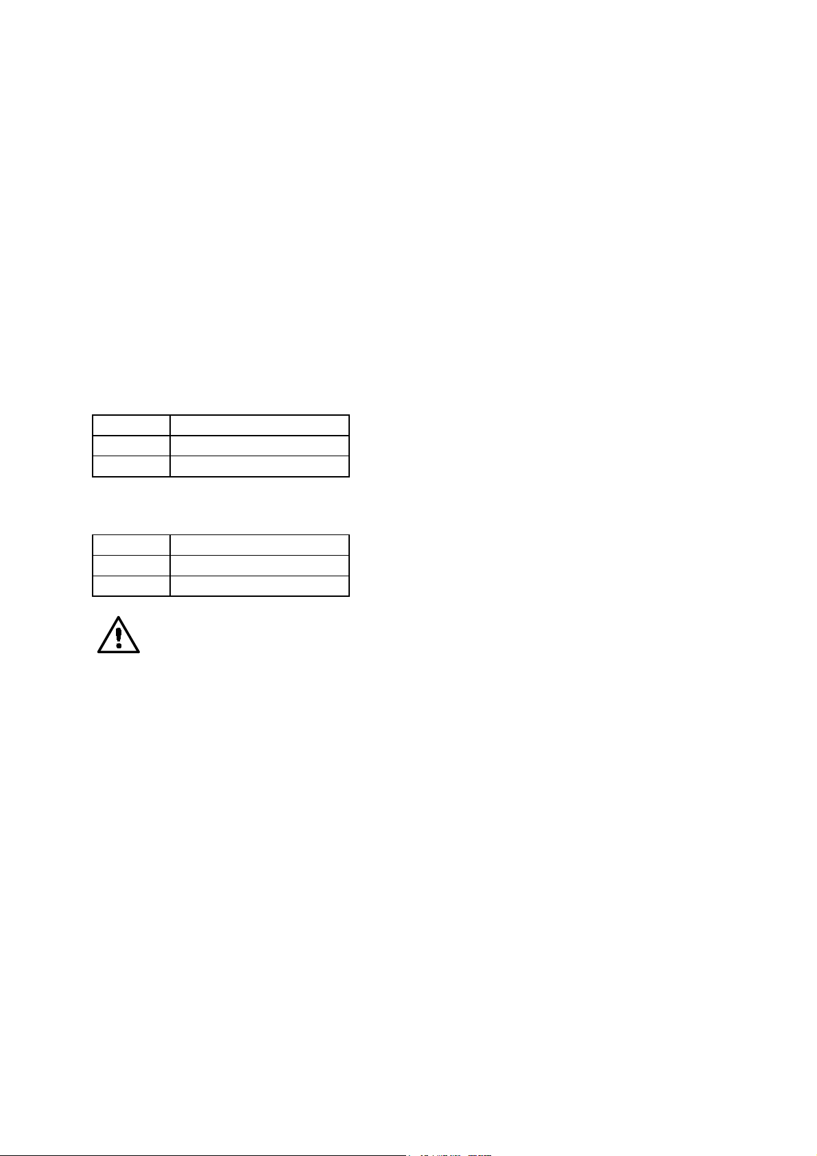
Sensor supply
The sensor supply is not short circuit proof.
The sensor supply is connected to connections 8 and 9. However, the
)
Terminal 8 +24 VDC +/- 20 % load dependent 50 mA
Terminal 9 0 V
Signal inputs
Measuring systems with incremental signals provide two square wave pulses. The
square wave pulses are displaced from one another by 90°. It is therefore possible to
detect the direction. This is referred to as a two channel layout.
If a measuring system with one square wave output is available, it is referred to as a
single channel layout. In this case direction detection is not available.
sensor supply must not be used for the supply of unearthed inductances or
capacitive loads.
Voltage Ripple Maximum permissible
current
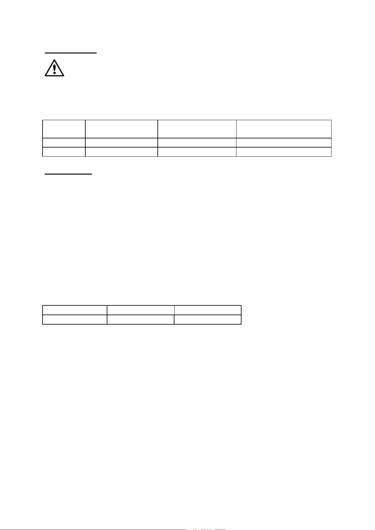
Single channel or two channel connection must be set on the AS8. The
)
Connection of the signal inputs is made on terminals 10 and 11. Connection terminal
11 is not used on the single channel layout.
Counting input Terminal 10 Terminal 11
The measurement parameters of flow rate and volume are derived from the square
wave signals.
)
)
settings required are made under menu reference „08“ at the “meter
input” position (see 4.1 overview of the input values).
Channel 1 Channel 2
The terms volume measurement and flow rate measurement are often
interchanged, however, they are two completely different measurement
parameters.
The indicator, the relay and the analogue output can be switched between
flow rate measurement and volume measurement, as desired. This is
achieved in the programming of the AS8 under the menü reference „7“. A
„0“ is set for flow rate measurement and a „1“ for volume measurement
(see 4.1 Overview of the input values).
BAS8-02.02-GB Page 7

3.2.1 How is the flow rate measurement activated ?
As soon as a medium flows through the volume counter a flow rate indication
appears. No special action is required. The instantaneous flow rate is indicated, as a
rule in litres per minute.
The AS8 must be adjusted to the actual volume counter that is connected.
)
3.2.2 How is the volume measurement activated ?
By volumetric measurement is implied the summation of the amount of a medium
which has flowed through a volume counter. As a rule the indication is in litres.
The procedure is given in section 4.2 What must be programmed when
connecting a volume counter?
The summation commences when the summation enable is switched.
)
The enable input is connected to terminal 12.
)
)
If there is a voltage of 24 V at the enable input, summation of the volume
commences. The measured values on the display change.
If there is a voltage of 0 V at the enable input, summation of the volume is
stopped. The measured values on the display do not change.
When the voltage at the enable input is changed from 0 V to 24 V the
summation is reset to zero. The determination of the volume starts again.
The AS8 must be set for the particular volume counter that is connected
The procedure is given in section 4.2 What must be programmed when
connecting a volume counter?
PAGE 8 BAS8-02.02-GB
3.3 Connecting the relay contacts
The AS8 has two relay contacts. The relays are designed as potential-free contacts.
That is to say, the user must input the potential at the base terminal.
The relays are provided with normally-open contacts. The switching
voltage is 24 V, maximum switching current is 1A. Voltages greater than
48 V must not be switched on any account.
Relay Contact ( Signal ) Common terminal (Base)
K0 Terminal 5 Terminal 7
K1 Terminal 6 Terminal 7
How do the relays operate ?
The function of the relays can be set as required, i.e. each relay can be allocated to
the flow rate or volume measurement parameters.
The relays can be set as required to flow rate measurement or volume
)
measurement. Thhis is achieved in the programming of the AS8 under the
menu reference „7“ at the „Relais 1“ or „Relais 2“ position. A „0“ sets the
flow rate position, a „1“ sets the volume measurement (see 4.1 Overview
of the input values).
An on and an off switching value can be programmed for each relay. The relay
switches when the switch-on value is exceeded. When the switch-off value is
undershot, the relay drops out again. The relays can be programmed as normallyopen or normally-closed.
The programming of the switch-on and switch-off values is given in
)
section 4.5 What must be programmed when connecting the relay
outputs?.
BAS8-02.02-GB Page 9
 Loading...