

Page 1

Auto Refkeratometer
Operations Manual
RB-525-B04
Page 2
INTRODUCTION
This manual contains information on correct handling and operational procedures as well as safety
consideration pertinent to KW-2000
Before carrying out measurement and/or adjustment, read the instructions thoroughly so that effective
operation is ensured. As this constitutes an important reference and user guide, keep it on hand at all times.
NOTE
The information contained in this manual is subject to change without notice.
While reasonable efforts have been made in the preparation of this document to ensure its accuracy,
you should contact your local distributor immediately, if any quarries arise due to editorial errors or
omissions etc.
If you find any imperfect collating or missing pages, contact your local distributor for replacement.
SAFETY CONSIDERATION
KW-2000 is a Class I, Type B medical instrument as well as LED Class 2 product.
This instrument complies with Medical Device Directive 93/42/EEC.
A great deal of consideration has gone into the design and manufacturing of this instrument with regard to
its operational ease, the patient's safety and well-being as well as to the reliability of the product.
For safer and more effective use, however, follow the points described in this manual.
This instrument is designed for professional use.
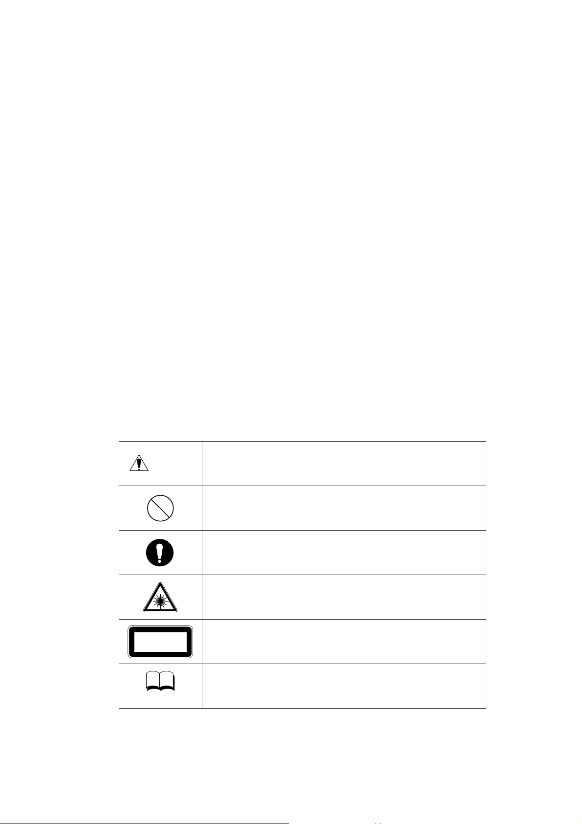
~ General Definitions of Safety Symbols ~
Personal injury or physical damage may occur when this warning
CAUTION
LED Class 2 Product
NOTE
is ignored.
General warning. Caution. Risk of danger.
Denotes general ban or prohibition.
General mandatory action.
Caution of invisible LED radiation.
Avoid exposure to beam.
Indicated inside of the device.
This device is an LED class 2 product.
Additional information which is important to the text or is
useful/convenient to know.
RB-525-B041
Page 3
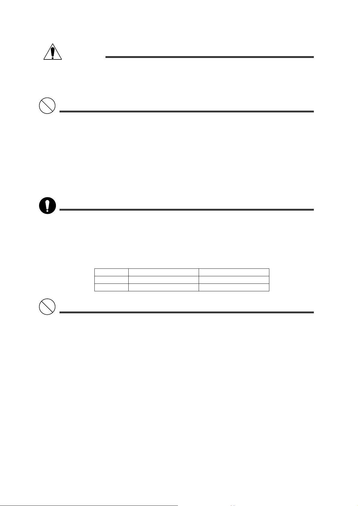
CAUTION
Always take great care when operating KW-2000. Malfunction or damage to the instrument could
occur.
Cut the power immediately if malfunction occurs during operation. Damage to the equipment or
personal injury will result. Consult your dealer, if repair work needs to be carried out.
At no time attempt to remodel or disassemble KW-2000. Damage to the instrument or personal injury
will result.
As KW-2000 is a precision optical instrument, operations must be carried out at all times by
experienced, authorized personnel. Damage to the equipment or personal injury will result.
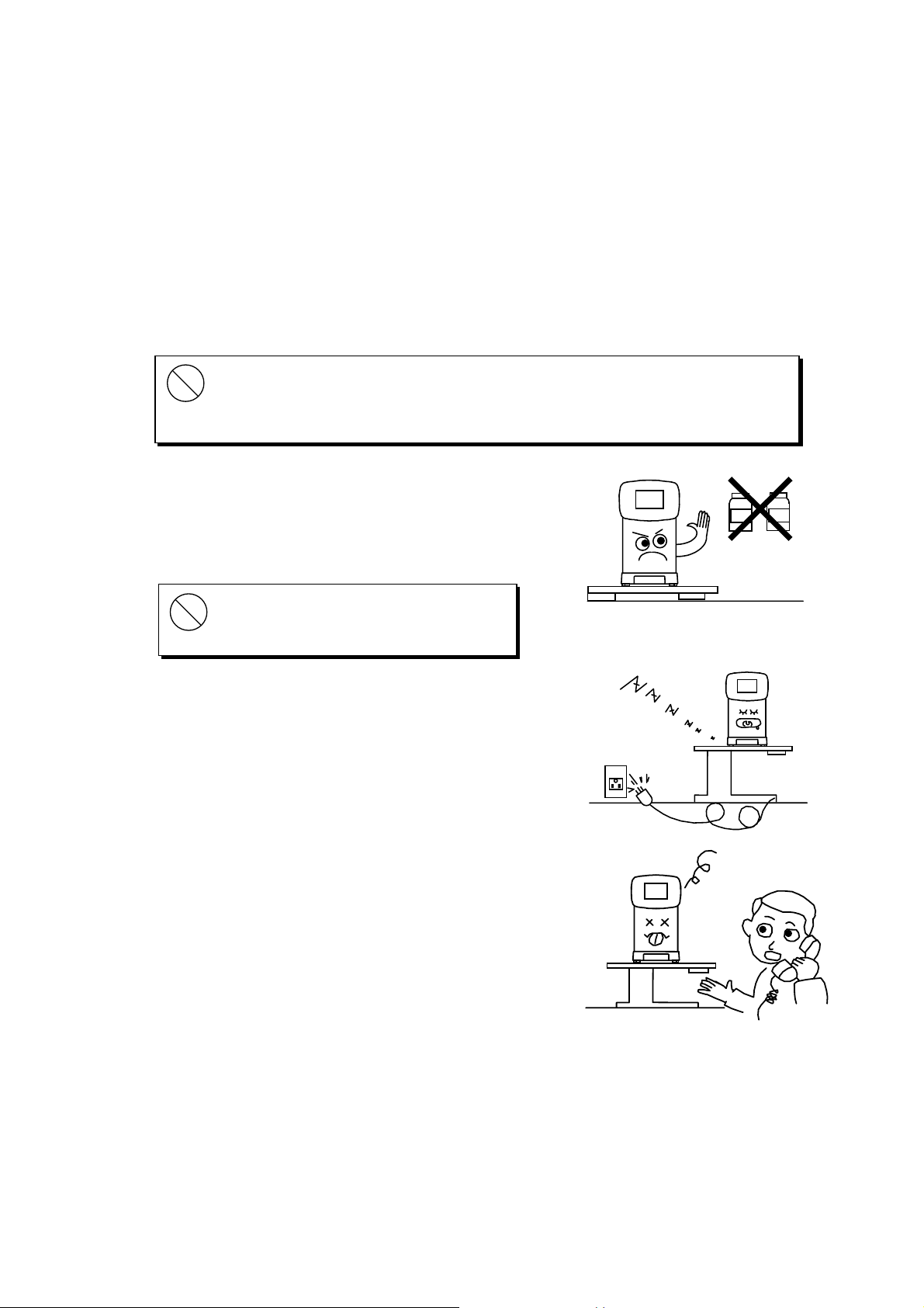
Avoid installation near TV or radio. The reception can be disturbed by electrical noise. Follow the
manual for the proper installation.
Never remove the plug from the outlet if your hands are wet. Electric shock or personal injury could
result.
Make sure the power cord is not damaged. Fire or electric shock may occur.
Do not touch the optical parts. Measurement accuracy will be adversely affected.
The power cord must be firmly connected to an electrical ground (safety ground) at the power outlet.
Personal injury may result form electric shock, etc.
If the instrument fails to work properly, you should not try to repair the fault. Consult your dealer
immediately.
The instruction in this manual ensures correct operations.
Observe the following environmental conditions for used and storage. Avoid dew condensation at all
time.
Temperature Relative humidity
Use +10°C to +40°C 30% to 85%
Storage –10°C to +60°C below 70%
Avoid the following conditions for storage and use of the instrument.
Where noxious gases or air pollutants are present.
Where dust and grit may occur.
Where oil fumes or greasy substances are emitted.
Where there are atmospheric concentrations of salt.
Near gas generation areas and places where dust accumulates.
Keep in a secure, stable situation. Do not expose to strong vibrations (areas of seismic activity) and
sudden shocks (this includes transportation) etc.
Where there is an inclination of more than 10 degrees.
Where voltage from the power sources rises or falls sharply during loading.
Where fluctuations in the voltage of the power source occurs.
Direct contact with sunlight.
If the instructions above are not followed, damage to the equipment or personal injury will ensue.
RB-525-B042
Page 4

Contents
Introduction............................................................................................................................. 1
Safety Consideration............................................................................................................... 1
Contents.................................................................................................................................. 2
Accessories............................................................................................................................. 4
1. Parts Identification............................................................................................................ 5
2. Conveyance and Handling Procedure ............................................................................. 6
3. Installation Environment................................................................................................... 6
4. Safeguard Summary........................................................................................................ 7
5. Preparation....................................................................................................................... 8
5.1 Setting ...........................................................................................................................................8
5.2 Applying Power .............................................................................................................................9
5.3 Standby.......................................................................................................................................10
5.4 Switch Function............................................................................................................ ...............11
6. Measurement................................................................................................................. 12
6.1 Measurement Flow......................................................................................................................12
6.2 Alignment ....................................................................................................................................13
6.3 Measurement Results .................................................................................................................14
6.4 Print Out......................................................................................................................................15
6.5 Kerato-Peripheral Measurement.................................................................................................16
6.6 IOL Measurement........................................................................................................................18
6.7 Menu Screen Setting...................................................................................................................19
6.7.1 Each Item Description....................................................................................................20
6.7.2 Optional Functions .........................................................................................................23
6.8 Auto Start Function......................................................................................................................27
6.9 Data Screen Function..................................................................................................................29
6.10 Power Saving Function .............................................................................................................30
6.11 Output Terminal.........................................................................................................................30
7. Tips for Effective Measurement......................................................................................31
8. Error Messages.............................................................................................................. 32
9. Contact Lens: Base Curve Measurement...................................................................... 33
10. Troubleshooting............................................................................................................. 34
11. Storage and Maintenance.............................................................................................. 35
11.1 Reloading Printer Paper............................................................................................................35
11.2 Fuse Replacement....................................................................................................................36
11.3 Storage......................................................................................................................................36
11.4 Confirmation of Measurement Accuracy...................................................................................37
11.5 Periodical Inspection and Maintenance ....................................................................................37
12. Specifications................................................................................................................. 38
RB-525-B043
Page 5
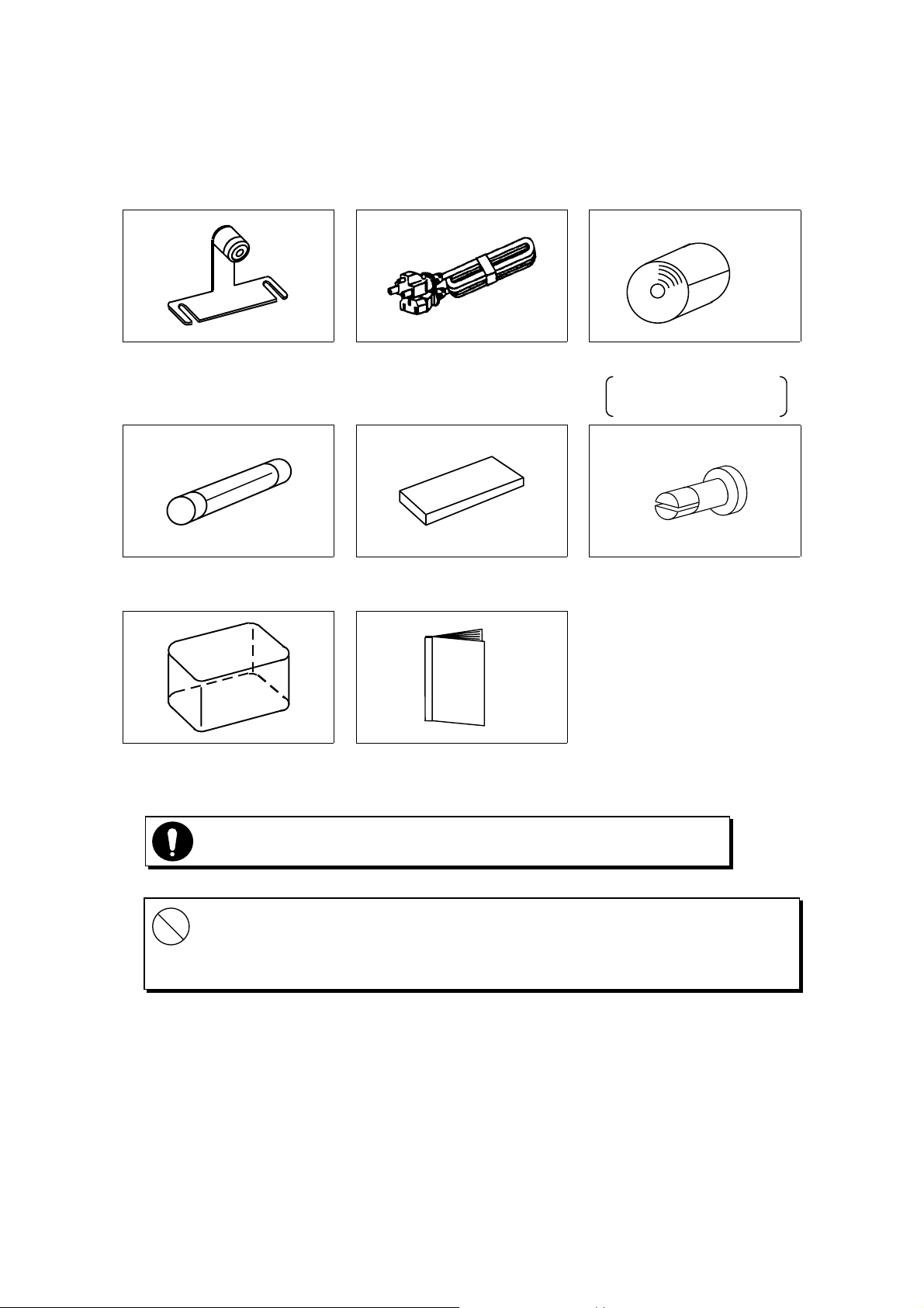
Accessories
Model eye: 1
(with a contact lens holder)
Fuse: 2
(T2A 250V)
Dustproof cover: 1 Operations manual: 1
Power cord: 1
(2.5m)
Pack of chin rest liners: 1
(1,000 sheets)
Printer paper role: 3
(width 57mm)
Two packed and o ne
installed into the body
Chine rest liner pin: 2
Use accessories specified by us to avoid any malfunction or failure.
Extra care should be taken for storage of a model eye. Avoid where the lens of the
model eye may be damaged as well as any dusty or humid/steamy environments.
Avoid direct sunlight, humidity and high temperature when storing printer paper
which is a thermal paper.
RB-525-B044
Page 6
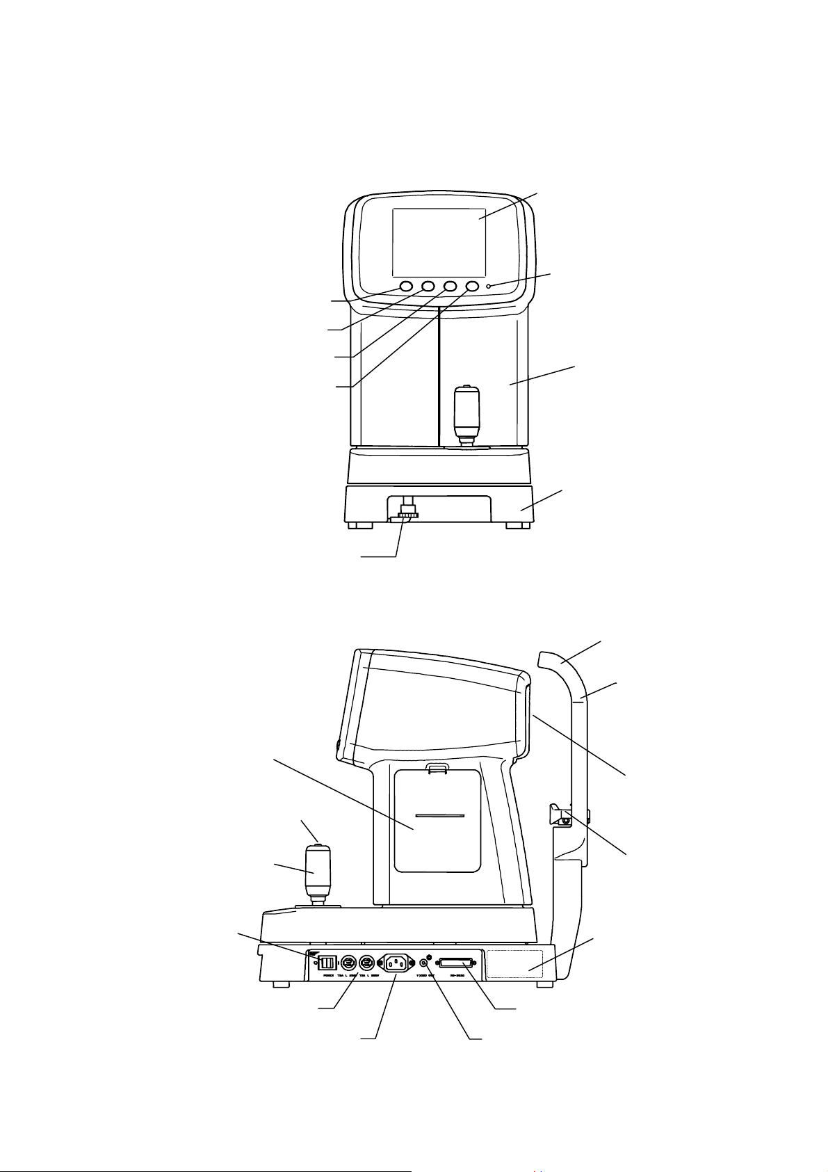
1. Parts Identification
y
IOL switch
Measurement mode selection switch
LCD monitor
Power indicator
Menu switch
Print switch
Anti-sliding lock
Printer
Bod
Base
Head rest
Eye mark
View window
Measurement start switch
Joystick
Power switch
Fuse holder
Power plug connector
External interface connector
External monitor output terminal
Chin rest
Rating plate
RB-525-B045
Page 7
2. Conveyance and Handling Procedure
When transporting the instrument, make sure that the body has been securely locked.
Center the body onto the base so that their edges are aligned. Push down the lock while turning right until
both body and base are firmly fixed to each other.
3. Installation Environment
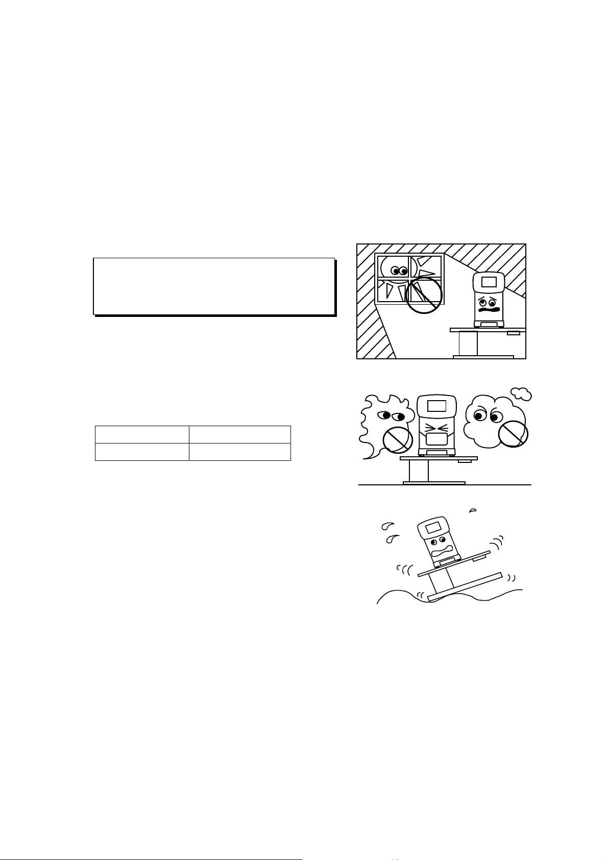
1) Do not expose the instrument's view window directly to the sunlight or bright lighting from other
sources.
Great care should be taken and avoid that the
examinee is exposed to strong light or glare. The
pupil will contract too much for measurement to
be carried out.
2) Do not operate in places where either dust or rubbish
accumulates. Environment with extremes in heat and
humidity should also be avoided.
Always follow the environmental requirements below
for installation.
Temperature
Relative Humidity
3) Keep away from inflammable or explosive gases as
well as storage areas housing medical supplies and
chemicals.
+10 °C ~ – 40°C
30 % ~ 85 %
Gases
Dust
4) Avoid installing where dew condensation may
accumulate. Also, avoid where the radical temperature
changes may occur.
5) Keep away from sites that may experience strong
vibrations or sudden shocks.
6) Malfunction is likely to occur if the instrument is improperly stabilized or accidentally overturns.
To prevent internal/external damage caused by sudden impact, set the instrument on a solid and
secure surface. Do not store in high, 'out of reach' places.
RB-525-B046
Page 8
4. Safeguard Summary
1. KW-2000 is a precision optical instrument. Always handle with care and avoid dropping it
accidentally.
2. Ensure that the instrument is properly grounded when connected to the power source.
3. Do not touch the optical parts with fingers and be sure to avoid dust, as their measuring accuracy
could be adversely affected and incorrect values may result.
When dust or fingerprints appear on the optical part, use a soft cloth to wipe off
the build-up. In case that the build-up is hard to remove, absolute alcohol is
recommended. Take great care when cleaning these parts as they are particularly
sensitive and fragile.
4. If the surfaces of the measuring unit and main unit including
the control panel are dirty, gently wipe with a dry cloth. For
hard to remove stains, a damp cloth or neutral cleanser is
recommended.
Avoid using organic solvents that will
damage the water based paint finish of the
instrument.
5. Clean the chin rest and head rest with the neutral cleanser.
For disinfecting them, especially where the examinee may
contact, hydrogen peroxide (Oxydol) is recommended.
6. If the instrument is not used for any length of time, remove
the power cord from the outlet.
7. When not in use, protect the instrument with a supplied
dustproof cover.
8. When the instrument fails to function properly, never
attempt to perform internal service or adjustment. Contact
your nearest registered agent, distributor or retail outlet.
Benzene
Thinner
RB-525-B047
Page 9
5. Preparation
5.1 Setting
(1) Set a roll of printer paper in the printer. Refer to '11.1 Reloading Printer Paper' for the procedure.
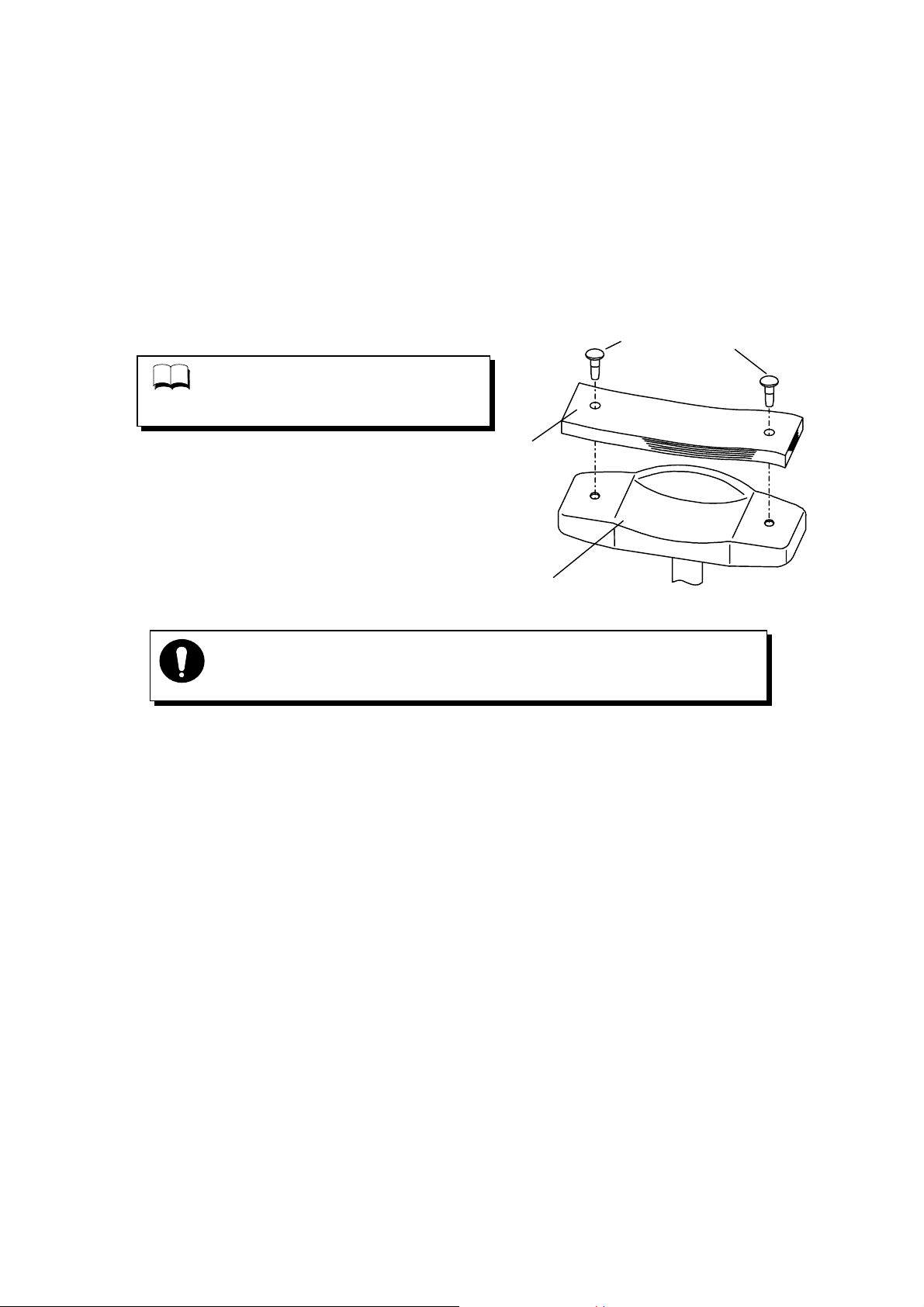
(2) Set and fix the chin rest liners with the chin rest liner pins on the chin rest.
Refer to the figure on the right.
Chin Rest Liner Pins
For sanitary consideration, disposing
NOTE
a sheet of the used chin rest liners after
every measurement is recommended.
Chin Rest Liners
Chin Rest
Always use the chin rest liners following above.
For sanitary consideration, disinfecting the chin rest with Oxydol is
recommended.
RB-525-B048
Page 10
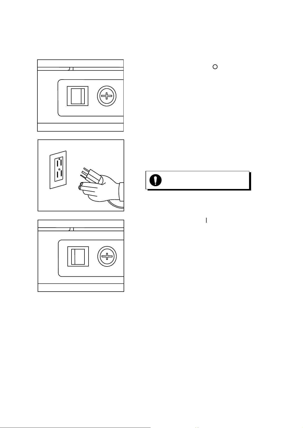
5.2 Applying Power
(1) Confirm that the power is 'OFF' ( ).
O
POWER
I
T 2A 250V
(2) Insert the power cord into the instrument's power plug
connector. Then insert the plug into a general-purpose
outlet.
(3) Turn the power switch 'ON' ( ).
Always make sure that the cable is
grounded.
O
POWER
I
T 2A 250V
RB-525-B049
Page 11
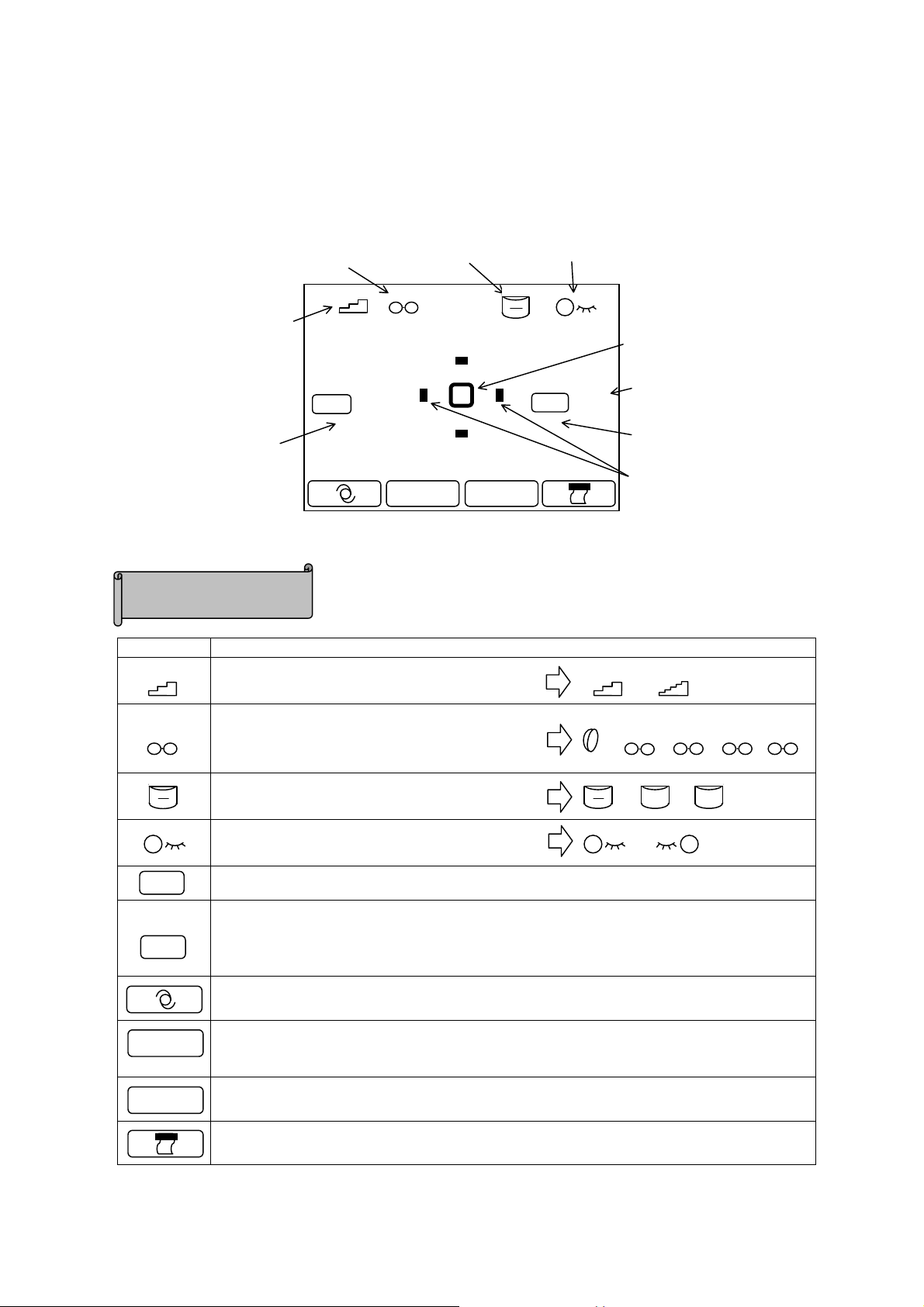
5.3 Standby
f
When the power is turned on, the screen as shown below appears on the LCD monitor, which is ready to
take measurements.
Vertex distance
Increment o
measurement values
Refraction data
display area
Icon Description
Cylindrical mark
( 0 )
12
R
/
K MENU
0.25
Ref.
(Normal measurement)
Eye selection indication
0 )
(
Ker.
Icon Description
0.25 0.25
Indicates increment of refraction data.
Reticle mark
Number of
measurement
Keratometry data
display area
Minimum pupil
diameter measurable
0.12
12 10 1513.512
Indicates corneal vertex distance.
Selection is available among 0, 10, 12, 13.5
and 15mm.
Indicates a mark for a cylindrical value.
Indicates an eye currently measured.
Ref.
Refractive measurement result is displayed in this area. Indicated values are S, C, and A.
Keratometry result is displayed in this area.
Indicated values are R1, R2, and A.
Ker.
K1, K2 and KC can be also indicated when the setting of KERATO in the menu screen is
changed.
Shifts to IOL measurement mode.
Measurement mode is switched. There are four measurement modes: Ref/Kerato
R
K
/
continuous measurement, Ref single measurement, Kerato single measurement, and
measurement corneal periphery.
MENU
Shifts to MENU screen.
Displays the measurement result on the screen and prints it out.
+ ±
RB-525-B0410
Page 12
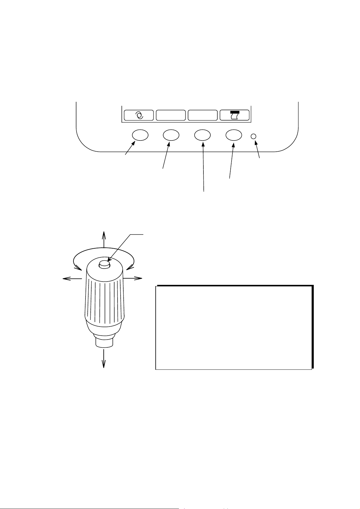
5.4 Switch Function
Operating switches below a LCD monitor correspond to the icons displayed on the bottom of the screen.
For normal measurement, each icon functions as below.
/
R
K MENU
Down
Left
IOL switch
Measurement mode selection switch
Forward
Measurement start switch: starts the measurement.
Up
Right
Backward
Operation of Joystick
• Forward: the body moves toward an examinee.
• Backward: the body moves toward an operator.
• Right/Left: the body moves to the right or left
respectively.
• The measurement unit moves up when the joystick
is rotated to the right, and moves down when rotated
to the left.
Power indicator
(It blinks when the saving
function is activated.)
Print switch
Menu switch
RB-525-B0411
Page 13

6. Measurement
6.1 Measurement Flow
(1) Rotate an anti-sliding lock clockwise to release it.
(2) Have the examinee place his/her chin on the chin rest and his/her forehead against the head rest.
Then, have him/her see a target.
Uncomfortable posture may cause fatigue to the examinee during measurement.
Vertically adjust the optical table or the chair to avoid that.
NOTE
(3) Check from the side and adjust the chin rest so that the examinee's eye level is in line with the eye
mark.
(4) When the eye appears on LCD monitor, carry out alignment for correct measurement.
Refer to '6.2 Alignment' for detail procedure.
NOTE
(5) Press the measurement start switch when the alignment mark reaches a center of the reticle mark, and
take measurement.
KW-2000 incorporates a high-speed continuous me asurement function.
To us the function, set DAT CLEARS (S) for OFF in MENU screen and keep pressing
NOTE
the measurement start switch during measurement.
RB-525-B0412
Page 14

6.2 Alignment
(1) Operate a joystick to bring a center of the subject eye onto a
reticle mark. When the subject eye is focused on, a kerato
ring appears.
If the eyelid is over the kerato ring, urge the
examinee to open the eye bigger .
NOTE
0.25
( 0 )
Kerato ring
R
12
/
K MENU
(
0 )
Ker.Ref.
(2) Keeping the reticle mark in the center of the subject eye, try
to focus the subject eye, and then, an alignment mark ( )
will appear.
Then, operate the joystick to bring the alignment mark ( )
into the center of the reticle mark.
(3) Keeping the alignment mark ( )in the center of the reticle
mark, focus on the subject eye and press the measurement
start switch.
(For auto measurement, measurement will automatically
start once the focus on the eye is achieved.)
Alignment mark
( 0 )
R
12
/
0.25
Reticle mark
0.25
12
( 0 )
K
MENU
0 )
(
Ker.Ref.
0 )
(
Ker.Ref.
NOTE
/
R
When focus is achieved, the kerato ring will become the thinnest.
K
MENU
RB-525-B0413
Page 15

6.3 Measurement Results
(
)
K
( 1 )
R
12
/
630
K MENU
R
(
1 )
er.
R1 7 . 8 5
R2 7 . 7 4
A90
Keratometry measurement result
Radi us of Cu rvat ure(m axim um)
Radi us of Cu rvat ure(m i nmum )
Axis An g le
Refr act i ve measure me nt re sult
Spherical value
Cylindrica l value
Axis angle
Pupillary Distance
Near p upillary distance
0.25
Ref.
S-4.75
C-0.25
A90A90
PD=67 NP D= 2
※ PC result is indicated after both right and left eyes are measured. The order of the eye to be measured is
not important.
NPD is indicated when some value is set in 'W-D (cm)' of menu screen only.
RB-525-B0414
Page 16

6.4 Print Out
Normally you can print out the measurement result by pressing PRINT switch after the measurement.
(The icon of PRINT switch in the monitor turns into blue during printing.)
A maximum of ten data is recorded for each eye and the most reliable among them is indicated as an
optimum value. The optimum value is indicated when each eye is measured over three times only.
The printout format, ALL, ECONO and OFF, can be set on the MENU screen.
∗
ALL : prints out a maximum of ten refractive data for each eye.
Optimum values only are printed out for the others except for the refractive data.
∗
ECONO : prints out only optimum values of all measurement data.
∗
OFF : prints out no data.
Regardless of the setting of the printout format, the measurement data stored in memory will be cleared
when the measurement start switch is pressed following the PRINT switch.
Sample printout when PRINT FORM is set for ALL
Message area
Refractive data
Keratometry data
Refractive data
Keratometry data
Pupillary distance
No. 00001
NAME
2002 11 20 14:29
VD=12
<R> SPH CYL AX
- 4.75 -0.25 62
- 4.75 -0.00
- 4.75 -0.00
----------------------------------------
- 4.75 -0.00
<R> mm D AX
R1 7.59 44.50 120
R2 7.57 44.50 30
AVE 7.58 44.50
CYL 0.00
<L> SPH CYL AX
- 4.50 -0.75 90
- 4.50 -0.75 90
- 4.50 -0.75 89
----------------------------------------
- 4.50 -0.75 90
<L> mm D AX
R1 7.59 44.50 120
R2 7.57 44.50 30
AVE 7.58 44.50
CYL 0.00
PD = 64
MODEL KW-2000(V1.00)
Date and time display
Right eye data
Opt imum value
indicated when
each eye is
measured more
than three times.
Left eye data
Sample printout
when PRINT FORM is set for
No. 00001
NAME
2002 11 20 14:29
VD=12
<R> SPH CYL AX
- 4.75 -0.00
<R> mm D AX
R1 7.59 44.50 120
R2 7.57 44.50 30
AVE 7.58 44.50
CYL 0.00
<L> SPH CYL AX
- 4.50 -0.75 90
<L> mm D AX
R1 7.59 44.50 120
R2 7.57 44.50 30
AVE 7.58 44.50
CYL 0.00
PD = 64
MODEL KW-2000(V1.00)
※Message area
You can print out registered characters in the range of 22 characters/line x 2 in the message area.
For registration, refer to
'6.7.2 Option Function: I. Message Input Function'
.
RB-525-B0415
Page 17

6.5 Kerato-Peripheral Measurement
P.K
MENU
KW-2000 incorporates a function to measure not only a center but also peripheries of a cornea.
Operation
(1) Press a measurement mode selection switch to switch over to P.K. mode.
P.K. measurement screen will appear and a 'measurement guiding mark' which indicates the
measurement position will appear on the top of the screen.
NOTE
Measurement guiding mark
R
P.K.
Measurement position:
Normally measurement is taken in the
following order: C→S→I→N.
C (Central): center
S (Superior): top
T (Temporal): temple side
I (Inferior): bottom
N (Nasal): nasal side
.
P.K. target selection switch
Measurement Guiding Mark
A measurement guiding mark changes its color and state to signal the measu rement
position and the end of measurement. Each color and state means as follows.
No color: where have not been measured yet.
Blue : where is going to be measured.
Light blue: where measurement is complete.
(2) Measure the center following the kerato measurement
procedure.
When the measurement is complete, the center of the
measurement guiding mark changes from blue to light
blue, and the next measurement position becomes blue.
Always start to measure from the center.
NOTE
However, it is not necessary when the
center is already measured in R/K mode or
Kerato mode.
Next measurement position (blue)
R
P.K.
P.K.
MENU
RB-525-B0416
Page 18

(3) Measure the corneal periphery.
(
)
Have the examinee look at the fixation target that is
illuminating. A measurement position in the guiding
Position already measured
Next measurement position
blue
mark is indicated in blue. Carry out alignment and
press the measurement switch.
When the measurement is completed, the guiding mark
R
changes blue to light blue and the next measurement
position becomes blue.
P.K.
For peripheral measurement, align the
NOTE
alignment mark to the center of the reticle
mark, not to the center of pupil.
H 7.55 V 7.51
P.K.
MENU
(4) Complete the peripheral measurement for all four positions. When it is completed, all positions of the
measurement guiding mark will turn to light blue.
Proceed to measure the other eye according to the procedure above.
When you wish to measure some position again, use P.K. target selection switch to
NOTE
move the cursor to the position you wish to measure.
When you can not take any data, or you do not need all data of the peripheral
measurement, you can skip some position using P.K. target selection switch.
In such a case, the result of the position measured only is displayed. The center,
however, must be measured all the time.
Printout Sample of P.K. Measurement
<R> mm D AX
R1 7.59 44.50 120
R2 7.57 44.50 107
AVE 7.58 44.50
CYL 0.00
Peripheral
T 7.66− H 7.55 −N 7.71
Measurement Result
V H AVE
e 0.554 0.396 0.475
<L> mm D
S 7.84
|
V 7.51
|
I 7.84
Data of Corneal Center only
When R/K or Kerato
measurement is also taken,
only optimum values are
printed.
Average of Vertical and
Horizontal Eccentrici ties
Horizontal Eccentrici t y
Vertical Eccentricity
RB-525-B0417
Page 19

6.6 IOL Measurement
KW-2000 has the function to measure the IOL (intraocular lens) implanted eye.
When measuring the IOL implanted eye, press IOL switch on the front panel of the body to activate the
function.
At this time, the icon for IOL switch as well as S, C, and A on the LCD monitor turns to purple.
( 0 )
R
12
/
K
MENU
0.25
S
C
A
IOL mode measurement screen
【
In IOL measurement mode, the IO L switch icon, S,
C, and A change to purple.
IOL measurement mode will be cancelled:
① when IOL switch is pressed again;
② when the measurement mode is switched to either K mode or P.K. mode;
③ when the data is printed out;
④ when the eye to be measured is switched from right to left or vice versa;
⑤ when the power is turned off.
R
No. 00001
NAME
(
0 )
Ker.Ref.
】
Measurement results of IOL measurement mode
are marked with 'IOL' on the left of each data.
2002 08 20 14:29
VD=12
<R> SPH CYL AX
IOL - 4.75 -0.00
IOL - 4.50 -0.25 60
IOL - 4.50 -0.25 131
----------------------------------------
- 4.50 -0.25 60
<L
Printout sample
【
】
If IOL mode is not set when IOL implanted eye is measured, error message may appear and
measurement may fail.
NOTE
RB-525-B0418
Page 20

6.7 Menu Screen Setting
Standard measurement mode is preset to be ready to use. However, you can easily alter the setting if
necessary.
To enter the menu screen, press a menu switch below the LCD monitor.
【Menu Screen】
STAR T MANUAL AUTO3 AUTO5
REF NORMAL QUICK( 3)
STEP 0.25 0.12
VD(mm) 0 10 12 13.5 15
CYL
KERA TO RADIUS DIOPT
PRINT FORM ALL ECONO OFF
PRINT OUT TOP BOTTOM
DATA SCREEN ON OFF
W-D(cm) OFF 30 35 40 45
TARGET LIGH T BRIGHT NORMAL DARK
SCREEN ADJ.
+
−
〉〉〉〉〉〉〉〉〉〉〉〉〉〉〉〉〉〉〉〉〉
±
SAVE(min.) OFF 3 5 10
BUZZER HIGH LOW OFF
DATA CLEAR(s) OFF 1 2 3
OPTION MESSAGE No. RS232C
DATE FORM YMD DMY MDY
DATE 2002/11/20
TIME 14:29:22
the First Screen the Second Screen
Change of Switch Function
Each switch function will change when you enter the menu screen.
Follow the icons indicated on the bottom of the screen, which corresponds to each
switch (see below).
The cursor moves downward on each setting menu.
The cursor moves upward on each setting menu.
Selection of the item in each setting menu. The cursor moves to the right.
Completion of the setting and return to the measurement screen.
RB-525-B0419
Page 21

6.7.1 Each Item Description
【The First Screen】
START Selects how to start measurement. Refer to '6.8 Auto Start Function' for detail.
MANUAL:
Measurement is taken every time the measurement switch is
pressed.
AUTO 3 :
Measurement is automatically started when the measurement
requirements are met. Three measurements are continuously
taken for each eye and automatically printed out when the
measurement is over.
AUTO 5 :
Measurement is automatically started when the measurement
requirements are met. Five measurements are continuously
taken for each eye and automatically printed out when the
measurement is over.
REF Selects refractive measurement manner.
NORMAL:
One measurement when the measurement start switch is pressed
once.
QUICK :
A set number of measurements are continuously taken when the
measurement start switch is pressed once. A maximum of ten
measurements is available.
A target moves only for the first measurement for the
continuous measurement. The target does not move after the
second measurement.
The setting of this item is invalid when START is set for either "AUTO 3" or " AUTO 5".
NOTE
STEP Selects the increment for refractive measurement.
VD(mm) Selects corneal vertex distance.
CYL Selects the sign for cylindrical value.
KERATO Selects the display unit for kerato measurement.
RADIUS : a radius of corneal curvature
DIOPT : a corneal refractive power
PRINT FORM Select printout format. Refer to '6.4 Print Out' for detail.
ALL
ECONO
OFF
: prints all data. (A maximum of ten data for each eye.)
: prints the optimal values only.
: no printouts.
PRINT OUT Selects direction of data printed out.
RB-525-B0420
Page 22

DATA SCREEN Measurement results stored in memory are displayed on the screen. Refer to '6.8
Data Screen Function' for detail.
ON :
OFF :
All measurement results are displayed on the screen.
No measurement results are displayed on the screen.
W-D(cm) Sets near work distance. When measurement is taken with this item set, a near
pupillary distance is automatically computed and indicated on the screen as well
as on the printout.
This function is activated only when refractive measurement is taken.
NOTE
TARGET LIGHT Sets the brightness of the target.
BRIGHT :
NORMAL :
DARK :
for brightening the target.
normal setting.
for darkening the target.
SCREEN ADJ. Brightness of a LCD monitor is adjusted or altered.
Switch functions will change in this item as below.
NOTE
•
(K・R>R>K>P.K.switch): makes the monitor brighter.
•
(IOL switch) : makes the monitor darker.
When you finish adjusting or altering, move the cursor to any other items except for
"SCREEN ADJ.", using or switch.
【The Second Screen】
SAVE(min.) Selects switchover time (in minute) to activate power saving function.
BUZZER Sets volume of buzzer at measurement.
HIGH : turns volume up.
LOW : turns volume down.
OFF : no buzzer.
DATA CLEAR(S) Sets the condition for clearing measurement data. (The unit is second.)
The measurement data can be cleared from memory when the measurement start
switch is pressed for the time set.
If this item is set for OFF, the measurement data is not cleared and continuous
measurement is taken when the measurement start switch is pressed.
RB-525-B0421
Page 23

OPTION Selects and sets optional functions. Refer to '6.7.2 Optional Function' for detail.
MESSAGE:
No. :
RS232C :
shifts to the screen for registering message.
shifts tot he screen for setting examinee's number.
shifts to the screen to set RS232C transmission parameters.
DATE FORM Selects display form of date.
YMD: year/month/ date
DMY: date/year/month
MDY: month/date/year
DATE Sets and corrects date.
TIME Sets and corrects time.
If you wish to correct date or time, move the cursor to the number you wish to change.
Month
Year
Date
2002/11/20
14:29:22
Hour
Minute
S
witch Functions will change in this item as below.
NOTE
•
•
: Increases the number.
: Decreases the number.
When you complete all settings or changes, press or switch to move the cursor to
any items other than TIME. Then, press switch to return the measurement mode.
Second
RB-525-B0422
Page 24

6.7.2 Optional Functions
Phone012(345)678
When you select the function you wish to set in '
screen.
【
Each Option Screen and Description
I. Message Input Function
Input
cursor
A
ABCDEFGHIGKLMNOPQRST
Cursor
UVWXYZabcdefghijklm
nopqrstuvwxyz012345
6789!"&'()*+<,‑./:;=
Move the cursor to the right.
Move the cursor to the left.
】
END
SET
Move the input cursor to any
given position in the input area.
Set the character.
OPTION
' of Menu screen, you can enter each option
When this function, you can print out registered
messages in the range of 22 characters/line x 2 lines.
When you select this menu, the screen on the
left will appears, and function of each switch
will change as shown on the left.
ABCOPTICI AN
Phone012( 345)678
ABCDEFGHIGKLMNOPQRST
UVWXYZabcdefghijklm
nopqrstuvwxyz012345
6789!"&'()*+<,‑./:;=
8
ABCOPTICIAN
No. :00001
NAME
2002 11 20 14:29
<R> SPH CYL AX
- 4.75 -0.25 62
〔
Print out sample
- 4.50 -0.25 60
END
SET
〕
(1) With or switch, select the
character you wish to input and confirm with
switch.
Then, the input cursor moves to the next input area
to be ready for the next input.
When you need to change the character
NOTE
already inputted, press switch to
move the input cursor to the character you
wish to input. Then, you can write over.
(2) When the setting is completed, move the input
cursor to 'END' and press switch to go
SET
back to the menu screen.
SET
RB-525-B0423
Page 25

II. No. Function
R
K
MENU
You can set or change the examinee's number, and select whether the number is displayed on the screen
and whether the number is printed out.
When you select this menu, the screen below will appear and function of each switch
will change as following.
Sets or changes the examinee's
number.
Selects print out setting of
examinee's number.
OFF: no print out.
ON : prints out the number.
Selects monitor display setting
of examinee's number.
OFF: no display
ON : displays on the screen
Move the cursor to select the item
you wish to change.
No.SET 00001 RESET
PRINT OFF ON
DISPLAY OFF ON
+
Set the examinee's number.
Return switch to return to
the measurement mode.
Move the cursor to the r ight and left to
choose the setting within each item.
Resetting Examinee's Number
When you wish to reset the examinee's number, move the cursor to RESET of No.SET
NOTE
and press the measurement start switch.
(1) Move the cursor to the item you wish to set/change
No.SET 00001 RESET
PRINT OFF ON
DISPLAY OFF ON
with switch and execute with
switch.
(2) When you complete the setting, press
switch to go back to the Menu screen
【Screen when DISPLAY is set to ON】 【Print out when PRINT is set to ON】
( 0 )
12
/
Ker.Ref.
00001
( 0 )
Examinee's
number
No. 00001
NAME
2002 11 20 14:29
VD=12
<R> SPH CYL AX
- 4.75 -0.25 62
- 4.75 -0.00
- 4.75 -0.00
----------------------------------------
- 4.75 -0.00
0.25
RB-525-B0424
Page 26

III. RS232C Setting Function
t
BAUDRATE 9600
BAUDRATE 9600
CHARACTER 8
PARITY NONE
STOPBIT 1
Move the cursor downward
o select the item you wish to
change.
Change the setting of the item selected.
The display changes every time the switch is
pressed. Press the ret urn switch at any give n
setting.
【Each Item Description】
1. BAUDRATE : selection of a transmission rate for a serial interface.
With this function, you can send the measure ment data
to an external computer through an interface. The data is
sent using ASCII CODE.
When you select this menu, the screen on the left
will appear and function of each switch will change
as shown.
Return switch to go back the
measurement mode.
BAUDRATE option Standard setting
38400bps
19200bps
9600bps
○
4800bps
2400bps
2. CHARACTER : selection of data bit
CHARACTER option Standard setting
8
7
3. PARITY : selection of transmission data check.
PARITY option Standard setting
EVEN
ODD
NONE
4. STOP BIT : selection of code to terminate data output.
STOP BIT option Standard setting
2
1
○
○
○
RB-525-B0425
Page 27

BAUDRATE 9600
67812345
516
81920
5
345
876
910
CHARACTER 8
PARITY EVEN
PARITY NONE
STOPBIT 1
【Connection method】
(1) Move the cursor to the item you wish to set/change with
switch and execute with switch.
(2) When the setting is completed, press
switch to go back to the menu screen.
KW-2000
1
2
1
14
Connection
D-Sub25pin D-Sub9pin
TXD 2 2 RXD
RXD 3 3 TXD
DSR 6 4 DTR
SG (GND) 7 5 SG (GND)
DTR 20 6 DSR
PC
Connect with a cross cable.
D-Sub25pin
Male
11 1312
1
17
21222324 2
D-Sub9pin
Female
Use a shield type of cable for the connection cable in order to protect the output
NOTE
data from noise.
※ If you have any inquiries about changes in transmission parameters and/or detail
connections, please direct them to the relevant agent or distributor.
RB-525-B0426
Page 28

6.8 Auto Start Function
KW-2000 incorporates Auto Start Function.
This function starts measuring automatically when alignment meets the measurement requirement, and
also prints out automatically when the measurement of both eyes completes.
When Auto Start Function is activated, measurement is always taken according
NOTE
to the setting of START regardless of REF setting in the menu screen.
START MANUAL AUTO3 AUTO5
REF NORMAL QUICK( 3)
STEP 0.25 0.12
VD(mm) 0 10 12 13.5 15
CYL
KERATO RADIUS DIOPT
PRINT FO R M ALL ECONO O F F
PRINT OUT TOP BOTTOM
DATA SCREEN ON OFF
W-D(cm) OFF 30 35 40 45
TARGET LIGHT B RIGHT NORMAL DARK
SCREEN ADJ.
0.25
( 0 )
0.25
+
−
〉〉〉〉〉〉〉〉〉〉〉〉〉〉〉〉〉〉〉〉〉
12
/
R
12
AUTO
K
AUTO
±
MENU
Ker.Ref.
(1) When you wish to measure with auto start function,
select 'AUTO3' or 'AUTO5' in 'START' of the Menu
screen
(2) Then, press switch to go back to the
measurement screen.
(3) Auto Start mode is activated when 'AUTO' and arrows
below 'AUTO' appear on the top of the screen (see on
the left).
You can start measurement from either right or left eye.
0 )
(
(4) Carry out alignment. Measurement will automatically
start when alignment is achieved.
For alignment, refer to '6.2 Alignment'.
NOTE
( 0 )
/
R
K
MENU
The arrow to urge the
shift flashes.
(
Ker.Ref.
0 )
When the measurement of one eye finishes, an arrow on
either left or right side you have measured will
disappear. In addition, an arrow to urge the shift to the
other eye will appear and flash in the center of the
screen.
The operator shifts the body of the unit to the
NOTE
eye which has not measured according to the
arrow.
When the body is shifted, the arrow flashing in
the center of the screen will disappear.
(5) Measure the other eye in the same manner.
RB-525-B0427
Page 29

(6) After both eyes are measured, the arrow will disappear and the measurement result will be
automatically printed out.
The data printed out depends on the setting of print out format.
NOTE
When the data screen is set for 'ON', the screen changes to display all optimal
values after both eyes are measured.
(7) If you wish to continue to measure with auto start function, realignment is necessary.
When you wish to cancel auto start function, change the setting of 'START' back
NOTE
to 'MANUAL' in the menu screen.
RB-525-B0428
Page 30

6.9 Data Screen Function
R) SPH
CYL
AX
AX
Data screen function allows you to check measurement results saved in the memory on the screen.
Displaying measurement data on the screen
START MANUAL AUTO3 AUTO5
REF NORMAL QUICK( 3)
STEP 0.25 0.12
VD(mm) 0 10 12 13.5 15
CYL
KERATO RADIUS DIOPT
PRINT FORM ALL ECONO OFF
PRINT OUT TOP BOTTOM
DATA SCREEN ON OFF
W-D(cm) OFF 30 35 40 45
TARGET LIGHT BRIGHT NORMAL DARK
SCREEN ADJ.
** RIGHT**
- 4.75 - 0.25 62
- 4.75 0.00
- 4.75 0.00
- 4.75 0.00
- 4.75 0.00
- 4.75 - 0.25 62
- 4.75 0.00
- 4.75 0.00
- 4.75 0.00
- 4.75 0.00
- 4.75 0.00
+
−
〉〉〉〉〉〉〉〉〉〉〉〉〉〉〉〉〉〉〉〉〉
PRESS START SW ‑>
±
mm D
R1) 7.59 44.50 120
R2) 7.57 44.50 107
AVE 7.58 44.50
CYL 0.00
S 7.58 T 7.66
V 7.51 H 7.55
I 7.84 N 7.71
e(ver) 0.554
e(hol) 0.396
e(ave) 0.475
RETURN
(1) Select 'ON' in 'DATA SCREEN' of the Menu screen.
When 'DATA SCREEN' is 'ON', the setting
of 'PRINT FORM' is invalid (see '6.7.1 Each
NOTE
Item Description'.
(2) After the measurement, press switch, and
the data screen will appear as shown on the left.
'I' mark will be indicated on the left side of
each refractive data as shown below when
NOTE
you measure with IOL measurement mode.
Example: SPH CYL AX
I - 4.75 - 0.25 62
(3) Displaying the data on the screen, press switch to change over the display as below.
All data of right eye
(RIGHT)
All data of left eye
(LEFT)
Refractive data
(REF)
(4) When you wish to print out the measurement data, press switch again.
(5) Press the measurement start switch to go back to the measurement screen.
Representative data
(ECONO)
RB-525-B0429
Page 31

6.10 Power Saving Function
Power saving function will start operating when switch operation is suspended with the power on.
(The switchover time (in minute) can be selected at 'SAVE' on the mode selection screen. )
To return to the measurement mode, press any switch (any switch on the front panel or the measurement
start switch).
Measur ement Mode
Power Indicator (PW) ON
Leave idling f or a set ting time
Power Saving Condition
Power Indicator (PW) flashing
Pr es s any switc h
Return to Measurement Mode
Power Indicator (PW) ON
6.11 Output Terminal
Video Terminal
This terminal outputs an NTSC video signal.
If you connect an external monitor such as a portable TV or similar unit to KW-2000 with pin plug (video)
cable, you can observe and check the same image that appears on the internal monitor screen of KW-2000
simultaneously.
RB-525-B0430
Page 32

7. Tips for Effective Measurement
(1) Do not allow external light to directly penetrate the room.
(2) Fluctuation of values during measurement may occur if the examinee looks something other than the
target. Urge the examinee to concentrate on the target set in front.
(3) Talk to the examinee in a relaxed and friendly manner, so as to allay any fear or doubt they may have.
(4) Inappropriate height of a chin rest or a chair will cause the examinee fatigue. Adjust the (optional)
instrumental table to establish the most comfortable and convenient position for the examinee.
(5) When the eyelash or eyelid interfere measurement, error will occur in measurement. Urge the
examinee to keep his/her eye wide open.
(6) Tear residue or eye mucus, etc. trapped on the corneal surface may cause measurement errors. Check
the surface with LCD monitor, and if you see something moving when the examinee blinks, remove it
before measurement.
(7) When the pupil of the eye to be examined is smaller than the minimum pupil diameter measurable,
correct measurement will be impossible. When the pupil is too small to take correct measurement,
make the surroundings (room) or the target darker to allow the pupil to dilate as much as possible.
(8) If the examinee's head moves during measurement, AXIS value will be adversely affected.
RB-525-B0431
Page 33

8. Error Messages
KW-2000 automatically evaluates measurement condition or result and indicates error messages if it is
invalid. Error messages also appear when abnormality is detected in its operational system.
When any error message appears, always check the system with a supplied model eye. If it appears when
no abnormality in system is detected, check the measured eye for eye disease or problem.
Message Cause/Explanation Corrective Action
RETRY
SPH OVER
CYL OVER
Motor fault.
EEPROM fault.
Printer head up
lever.
Printer head heat
over.
Printer cutter fault.
Failed to capture eye image because
the examinee blinks or moves during
measurement or the examined eye has
an eye disease.
Exceeded spherical measurement
range (–25D to +25D). (when VD =
0 )
Exceeded cylindrical measurement
range (0 to ±10D) .
Detected abnormality in motor control
system.
Failed to initialize.
Printer head is up. Close the printer head.
Printer head is overheated.
A paper jam occurred at a printer
cutter or the printer cutter did not
move for some reason.
Realign precisely and take measurement
again. Consult your dealer immediately if
the message reappear.
Do not try to repair by yourself.
Cut the power and turn it back on. Consult
your dealer immediately if the message
reappear.
Do not try to repair by yourself.
Cut the power and stop using until the head
cools off. Consult your dealer immediately
if the message reappear.
Do not try to repair by yourself.
Always cut the power, and check on the
paper jam.
If the message reappears without the paper
jam, consult your dealer immediately.
Do not try to repair by yourself.
Paper empty.
No printer paper.
Set the printer paper.
See '11.1 Reloading Printer Paper.'
RB-525-B0432
Page 34

9. Contact Lens: Base Curve Measurement
You can measure a base curve of a hard contact lens with KW-2000.
To do so, attach a contact lens onto a contact lens holder of the model eye as following.
(1) Put a small amount of water on a concave side of the contact lens holder.
(2) Place the contact lens so that its convex side faces the holder.
Contact Lens Hold er
Model Eye
Contact Lens
(3) Confirm the contact lens is firmly adhered to the holder and does not slip down, set the model eye
unit to measure.
RB-525-B0433
Page 35

10. Troubleshooting
If there are any malfunction found, refer to the table below to take appropriate measures.
CAUTION
Symptom Causes and Measures
The monitor and power indicator are not
turned on.
Fuse is blown when the power switch is
turned on.
The monitor display suddenly disappears.
The main body can not be moved in a
horizontal direction.
The moving parts such as a joystick are not
moving appropriately.
The apparatus does not print out.
Never disassemble, modify or repair the instrument.
Personal injury may result from electric shock.
• The power cord may be not properly connected. Make
sure to connect it securely.
• Fuse may be blown. If so, replace it to the new one.
• Contact your local distributor immediately.
• The saving function may be activated.
Press any switch to deactivate the saving function.
• Anti-sliding lock may be locked. Unscrew the lock
under the base.
• Do not force to move the part. Contact your local
distributor or service person.
• Check the papers being set. Reload them if the papers
are out.
• PRINT FORM in the MENU screen may be set for
OFF. Change the setting.
The printer papers come out but no printing.
The date setting becomes inaccurate.
Contact your local distributor immediately if the situation does not improve even when the measures
mentioned above are taken.
• The printer paper may be set in a wrong direction. Set
the paper properly.
• The battery inside the apparatus may be dead. Keep the
power on for 24 hours to recharge it.
RB-525-B0434
Page 36

11. Storage and Maintenance
11.1 Reloading Printer Paper
1) Remove a printer cover and take a printer paper shaft
out.
2) Lift a printer cutter part and pull up a head-up lever.
3) Set a roll of printer paper, paying attention to direction
of the paper rolled up.
The loose end of the paper should be drawn
NOTE
forward in a counterclockwise direction.
4) Insert the loose end of the paper behind a rubb er roller.
Press print switch more than one second to feed the
paper out.
Printer cutter part
Printer cutter part
Head-up lever
Knurl
Never pull the paper out.
NOTE
Pulling the paper may cause the paper
output incorrectly or jammed.
5) Draw the paper through the printer cutter slot and
lower the head-up lever and the printer cutter back to
the original positions.
6) Draw the paper a cutter slot of a printer cover and
reattach the printer cover to complete the procedure.
Always use the specified printer paper only.
The paper other than the specified one may
cause a paper jam or fade in printing.
Rubber roller
RB-525-B0435
Page 37

11.2 Fuse Replacement
When replacing a fuse, unplug the power cord from the unit
CAUTION
When a fuse is blown, remove a fuse holder at the side of a main unit for replacement.
Pushing the fuse holder, rotate it in the direction of the arrow below and you can remove it.
Fuse Holder
before removing the fuse holder.
You may be in danger of electric shock if you remove the fuse
holder without unplugging the power cord.
Fuse
Rotate the holder counterclockwise.
11.3 Storage
(1) Points to be checked for long-term storage
Turn the power switch OFF.
Remove the power cord from the outlet.
Lower the optical unit to the bottom (original position).
Secure the body with the anti-sliding screw lock.
Put a dustproof cover on the optical unit.
(2) Notes on storage environment
Avoid storage under the following conditions.
Where dust accumulates.
Where water may get on the unit.
Where temperature and humidity are high.
Where sunlight directly contacts.
Unstable and/or high place.
Always use the specified fuse (T2A 250V).
NOTE
Always follow the environment conditions below for storage.
Environmental Conditions
Temperature Relative Humidity
−10℃ ~ +60℃ below 70%
Always check above whenever you store or do not use KW-2000 for a long time.
When you reuse the instrument after long-term storage, operate according to instruction in
' 5. Preparation.'
RB-525-B0436
Page 38

11.4 Confirmation of Measurement Accuracy
It is extremely important to check operation and accuracy of the instrument using a supplied model eye.
We recommend you to check accuracy periodically.
When the measurement result of the model eye falls anywhere within the tolerance listed below,
measurement should be considered reliable and accurate. When the result exceeds the tolerance, contact
your dealer immediately.
Model Eye Data
SPH CYL R
Indicated value ±0.25 0 ±0.25 Indicated value ±0.03
※Precise value of the supplied model eye is indicated on the model eye stand (VD =12).
Model eye
Note for setting of model eye
NOTE
Remove a contact lens holder cap and set a model eye, checking it is not inclined in any
directions.
When the model eye is inclined, CYL value can not be correctly measured.
Set the model eye at the position where an alignment mark is located inside a reticle
mark and good focusing is achieved.
When conditions above have been satisfied, proceed to measurement.
11.5 Periodical Inspection and Maintenance
To prevent malfunction and accidents and maintain the performance and reliability of the product, it is
recommended to request your distributor for the periodical inspection and maintenance once a year.
The periodical inspection and maintenance include inspection of the function and performance of the
product, and cleaning, adjustment and replacement of consumable parts if necessary.
RB-525-B0437
Page 39

12. Specifications
Sphere (S)
Cylinder (C)
Axis (A)
Sphere
Measurement Accuracy
Cylinder
Radius of
Corneal Curvature
Keratometry Measurement Range
Vertex Distance 0, 10, 12, 13.5, 15mm
Minimum Pupil Diameter
PD Measurement Measurement range 85mm (step: 1mm)
Measurement Time
Printer Thermal line printer with automatic cutter (paper width 57mm)
Internal Monitor 5.6 inch LCD monitor (color)
Shifting Range for Sliding Body
Vertical Adj. Range for Chin Rest
Dimensions
Weight approx. 15kg
Data Output
Power Source
Consumption 80VA
Power Saving Function
Corneal
Refraction
Cylinder
Axis
φ2.3 mm
Refractive measurement
Keratometry measurement
back/forth ±17mm right/left ±43mm up/down ±17.5 mm
±30mm
245 mm (W)×422 mm (D)×429 mm (H)
RS232C interface
Video Terminal
100〜240V
50/60Hz
OFF,3,5,10min.(switchable)
-25〜+25D
0〜±10D
0〜180º
between −10〜+10D : ±0.25D
beyond ±10 : ±0.5D
±0.25D
5.0〜10.0mm
33.75〜67.5D
0〜±9D
0〜180°
(step: 0.12/0.25D)
(step: 0.12/0.25D)Refractive Measurement Range
(step: 1°)
(step: 0.01mm)
(step: 0.12/0.25D)
(a refractive index of cornea:
n = 1.3375)
(step: 1°)
approx. 0.07 sec.
approx. 0.07 sec.
Production Year
The second digit of serial number represents a production year of each instrument. The serial number is
indicated on the nameplate that is on the side of body. See below.
92AG0103
This number is the last digit of the production year.
In this example, the production year is 2002.
RB-525-B0438
Page 40

Life Science Division
p
No.4-14, 3-chome, Nihonbashi-Honcho, Chuo-ku, Tokyo 103-8433, Japan
Phone: 81(3) 3279-7312
Facsimile: 81(3) 3245-1109
Manufacturer
RyuSyo Industrial Co., Ltd.
Kagawa Factory
958 Ikeuchi, Konan-cho,
Kagawa-gun, Kagawa 761-1494 JAPAN
20001 So. Vermont Ave. Torrance,
CA 90502, U.S.A.
Phone: 1(310) 327-1913
Facsimile: 1(310) 327-4177
EU Re
resentative
Immermannstrasse 65A 40210
Dusseldorf F.R. Germany
Phone:19 (211) 35-3444/45/46
Facsimile: 49(211) 161952
Printed on recycled paper.
RB-525-B04
Prepared: 2002. 12. 4
 Loading...