

Page 1

HAND-HELD FUNDUS CAMERA
Kowa
INSTRUCTION MANUAL
Page 2
INTRODUCTION
Accept our congratulations on your purchase of Kowa's HAND-HELD FUNDUS CAMERA . This manual provides
descriptions of the operating procedures of
Please read this entire manual carefully to assure that the instrument can demonstrate its full capabilities and be used
effectively. After you have finished reading it, please keep it in an easily accessible location near the instrument for future
reference.
along with important precautions to be observed during its use.
Operational Considerations for Safety and Accident Prevention
This manual describes important precautions to be observed during its use to assure that the instrument can be used safely
without causing any damage to the body and property of its purchaser and other persons. The designations and their
pictorial symbols have the following meanings. These should be fully comprehended before reading the text of this manual.
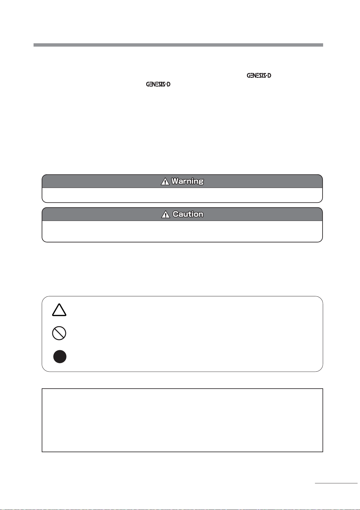
■ Meanings of designations
If the instrument should be operated wrongly, there may occur a danger of causing death or serious injury.
If the instrument should be operated wrongly, there may result an injury to the body (not so serious as to cause death
though) or damage to property.
●1 : An injury to the body means any injury, burn, electrical shock and so forth that will not necessitate hospitalization or
long-term outpatient treatment.
●2 :Damage to property means an extensive damage to the house and household goods as well as the domestic animal
and pet.
■ Meanings of symbols
Indication of any danger (including warning and caution)
What is warned is explicitly and pictorially indicated by a picture or its associated message on or near a
pictorial symbol.
Graphical indication of prohibited operation (prohibitive item)
What is prohibited is explicitly and pictorially indicated by a picture or its associated message on or near a
pictorial symbol.
Indication of mandatory action (obligatory item)
What must be always done is explicitly and pictorially indicated by a picture or its associated message on or
near a pictorial symbol.
■ Exclusion
Kowa is not responsible for:
● Any damage caused by fire, earthquake, third party's action, any other accident or user's intentional or unintentional
error, abuse or use under abnormal conditions;
● Any damage resulting from use of the product or its malfunction (e.g., operating loss, shutdown, change/loss of stored
data and so forth);
● Any damage resulting from disobedience of what is described in the instruction manual; and
● Any damage resulting from, for instance, malfunctioning of the instrument caused by a combination of connected
devices.
P - 1
Page 3

Unplug
Unplug
Unplug
Obligatory
Obligatory
Obligatory
If any abnormal smell or sound, or overheating or smoke should be detected, turn OFF the instrument
immediately and then unplug it.
If it should continue in use, a fire may break out on the instrument resulting in its malfunctioning. Contact
your Kowa dealer where you purchased it or your nearest repair shop for inspection.
Before replacing the electric flash light tube, make sure that the instrument is turned OFF and the plug has
been pulled out of the wall outlet. Allow at least five minutes to cool it off before replacement.
Otherwise, you may burn your fingers on the hot tube and/or get an electrical shock.
When replacing the fuse, make sure the instrument is turned OFF and unplugged out of the socket. If the
fuse holder cover is removed with the instrument unplugged, you may get an electrical shock.
Make sure that the instrument or AC adapter is properly plugged into the socket.
If not, there may occur a fire or you may get an electrical shock.
Use an accessory or designated fuse.
Otherwise, the instrument may malfunction or a fire may break out.
Make sure that the instrument is properly grounded to protect the body.
Put the plug in the three-core socket with ground wire.
Otherwise, you may get an electrical shock.
Prohibitory
Disassembly
prohibited
Prohibitory
Prohibitory
Prohibitory
Install in a location away from, for instance, a cup containing liquid. If liquid should be spilled into the
instrument, you may get an electrical shock. If so, turn OFF the instrument and then unplug it from the
socket. Contact your Kowa dealer where you purchased it or your nearest repair shop for inspection.
Do not disassemble, modify or repair the instrument yourself.
Otherwise, there may occur a fire and resultant instrument malfunctioning or your may get an electrical
shock and a bodily injury.
Contact your Kowa dealer where you purchased the instrument for repair.
The product assembled by yourself will not get warranty or any other service.
The socket or plug board must not be loaded in excess of its rated capacity.
If the main power cable should share an outlet with many other devices, there may occur a fire or you may
get an electrical shock.
If any metallic object in air vent slots should be inserted, there may occur a fire and resultant instrument
malfunctioning .or you may get an electrical shock.
Do not damage the power cable. If it should be damaged, there may result a fire or you may get an
electrical shock. Therefore, strictly observe the following:
-Neither modify nor damage the power cable.
-Do not place any heavy object on the power cable or pull it with a sudden jerk.
-Neither bring the power cable close to any hot surface of heater nor directly heat it.
P - 2
Be sure to use an accessory or designated lamp.
Otherwise, there may occur a fire or resultant instrument malfunctioning.
Obligatory
Page 4
Prohibitory
Prohibitory
Prohibitory
Prohibitory
Prohibitory
Prohibitory
Prohibitory
For unplugging from the socket, pull the power cable with its plug being held by your hand.
Otherwise, there may occur a fire or you may get an electrical shock.
Do not plug into or unplug out of the socket with your wet hand to avoid an electrical shock.
Do not place the instrument in an unstable location, for instance, on a shaky base or a tilting surface.
Otherwise, if it should drop off or fall over, you may get injured.
Do not replace the electric flash light tube and the illumination light immediately after their service.
Otherwise, you may burn your fingers on the hot surface of the tube or lamp. Allow 30 minutes or so to
cool it off before replacement.
Do not increase the amount of illumination light more than is required. Otherwise, the eye may get a pain
or injured.
For illumination and photography, do not select any higher exposure than it is required
Otherwise, the examined eye may suffer a pain or disorder.
Be careful about the gap between the light projecting prism and the patient's face. Otherwise, when
bringing the fundus camera unit closer to the patient, the prism may touch and hurt his or her face (the
eye, nose and so on).
Prohibitory
Prohibitory
Unplug
Prohibitory
Do not use the instrument in a location having too much moisture, dust, soot or steam. In such a location,
there may occur a fire or you may get an electrical shcok.
Do not touch the instrument with your wet hand to avoid an electrical shock.
If there is no need to use it for a long period of time, store the instrument with its power cable disconnected
from the socket.
Otherwise, there may occur a fire.
Use or carry the instrument with its being firmly held by your hand. Otherwise, if it should drop off, you
may get injured.
P - 3
Page 5

OPERATING PRECAUTIONS
●Carefully handle the instrument so that a strong shock will not be exerted on it. After it sustained a strong shock or
damage resulting from dropping off or any other mishandling, do not turn on the instrument.
●The instrument should be placed or stored in a place free from dust, high temperatures, high humidity and direct
sunlight. The environmental conditions described below should be observed strictly.
in operation In storage and transportation
Environmental temperature 10 to 40°c -15 to +55°c
Relative humidity 30 to 75% 10 to +95%
●When not in use, make sure the camera unit is protected by its objective lens cap or cover.
●If it has not been in service for a long period of time, make sure the instrument has no abnormality prior to use.
●Be careful not to let any condensation form on this instrument when in use, storage, or transportation.
Precautions in operating electric system
●Be careful about where the camera is placed to keep its power plug from being disconnected during fundus photography.
●If the plug should accidentally come off, be sure to turn OFF the power switch before putting it again into the socket.
●If you put the plug back into the socket with the power switch ON and as a result any abnormality should occur on the
circuit inside of the power supply unit, be sure to turn OFF the power switch and then wait for a while before turning it
ON again.
●The input voltage should be maintained within ±10% of the rated voltage.
●Do not turn the power switch ON and OFF in succession. Allow an interval of at least 5 seconds between switch
operations. Be sure to turn OFF the power switch before plugging and unplugging.
●The power line from the wall outlet should be exclusively used for the fundus camera.
Other precautions
●The manufacturer is not liable for malfunctions or injuries resulting from maintenance or repairs performed by a person
other than a designated repair shop.
●The manufacturer is not liable for malfunctions or injuries resulting from modification, maintenance or repairs using
parts other than designated repair parts.
●Because the camera is composed of precision parts, it needs a special set of tools for adjustment. Do not attempt to
disassemble or adjust them by yourself.
●"Compact Flash" is U.S. Sun Disk Corporation's registered trademark.
●"Windows" is Microsoft Corporation's registered trademark.
TM
and marks are not indicated in the text of this manual.
●
Disposal Precautions
●When disposing of this instrument, comply with the regulations of countries or areas in which the instrument is used.
P - 4
Page 6

Operational Precautions in Use of Hospital Grade Electrical Equipment of Medical
Electrical Equipment (Safety and Accident Prevention)
This section describes general precautions in use of medical electrical equipment based on Notification No. 495 of the Pharmaceutical Affairs Bureau of the Ministry of Health and Welfare dated June 1, 1972.
1. Only qualified personnel should operate this equipment
2. The following items shall be considered when installing equipment.
(1) Install in a location away from water or accidental splashing.
(2) Install in a location which will not be adversely affected by atmospheric pressure, temperature, humidity, ventilation,
sunlight, dust, air containing salt, sulfur and other substances.
(3) Take care to protect the equipment against tilt, vibration and strong impacts, for instance, during transportation.
(4) Equipment must not be installed in locations where chemicals are stored or gasses are generated.
(5) Be careful with the radio frequencies, voltages and allowable amperes (power consumption) of the power supply.
(6) Make sure that all batteries are installed properly and in good working order (discharging curve, polarity, and so forth).
(7) Properly connect ground wires.
3. The following items shall be considered when using the instrument.
(1) Make sure that equipment activates properly after checking switch contact. polarity, dial setting and meters and so
forth.
(2) Make sure that the instrument is properly grounded.
(3) Make sure that all cables are properly connected and secured.
(4) Use of other instruments and appliances on the same power circuit is liable to cause errors and incorrect flash output
resulting in incorrect diagnosis or hazards.
(5) External circuits and connectors that may come in direct contact with the patient must be checked frequently.
(6) Before operation, make sure that the camera back battery is sufficiently charged.
4. The following items shall be considered when using the instrument.
(1) Be sure to minimize the time and quantity required for diagnosis and treatment.
(2) Always assure that the equipment and patient are in good condition.
(3) When an abnormality is found in the equipment and patient, take proper measures: for instance, stopping the instru-
ment while assuring the patient's safety.
(4) Do not allow the patient to touch any part of the equipment where he or she is not instructed to do so.
5. The following items shall be considered after using the instrument.
(1) Follow a specified procedure of setting their control switches, dials and so forth to their original position before turning
OFF the instrument.
(2) Do not pull off cables by your hand to avoid exerting an excessive force on them.
(3) The following shall be considered regarding storage location.
(a) Store the instrument in locations free from splashes of water.
(b) Store in a location which will not be adversely affected by atmospheric pressure, temperature, humidity, ventila-
tion, sunlight, dust, air containing salt, sulfur and other substances.
(c) Take care to protect the instrument against tilt, vibration and strong impacts, for instance, during transportation.
(d) Equipment must not be stored in a location where chemicals are stored or gasses are generated.
(4) Clean and rearrange accessories, cables, cable restraints and the like in a proper manner.
(5) The instrument must be cleaned beforehand so that there will be no problem with subsequent service.
6. If it has some trouble, affix on the equipment a label describing the trouble and then ask a repair shop for repair .
7. Equipment shall not be modified.
8. Maintenance and inspection
(1) Periodically check the equipment and its components for any abnormality.
(2) If you have not used it for a significant period of time, check the instrument beforehand to assure that it is in normal
condition and operates safely.
9. Be careful of the possibility that incorrect operation may be caused by strong electromagnetic waves.
This instrument may suffer from incorrect operation when surrounded by strong electromagnetic waves. Electromagnetic
waves emitted by this instrument may also affect other external instruments.
General examples
(1) Electric waves emitted by cellular phones may cause unexpected incorrect operation.
(2) Use of this instrument may cause incorrect operation of a pacemaker.
P - 5
Page 7
Outline
Kowa is a compact, lightweight hand-held fundus camera which is capable of photographing mydriasis in color.
This instrument is equipped with a digital camera which provides 2.0 million pixels of resolution and a LCD monitor screen.
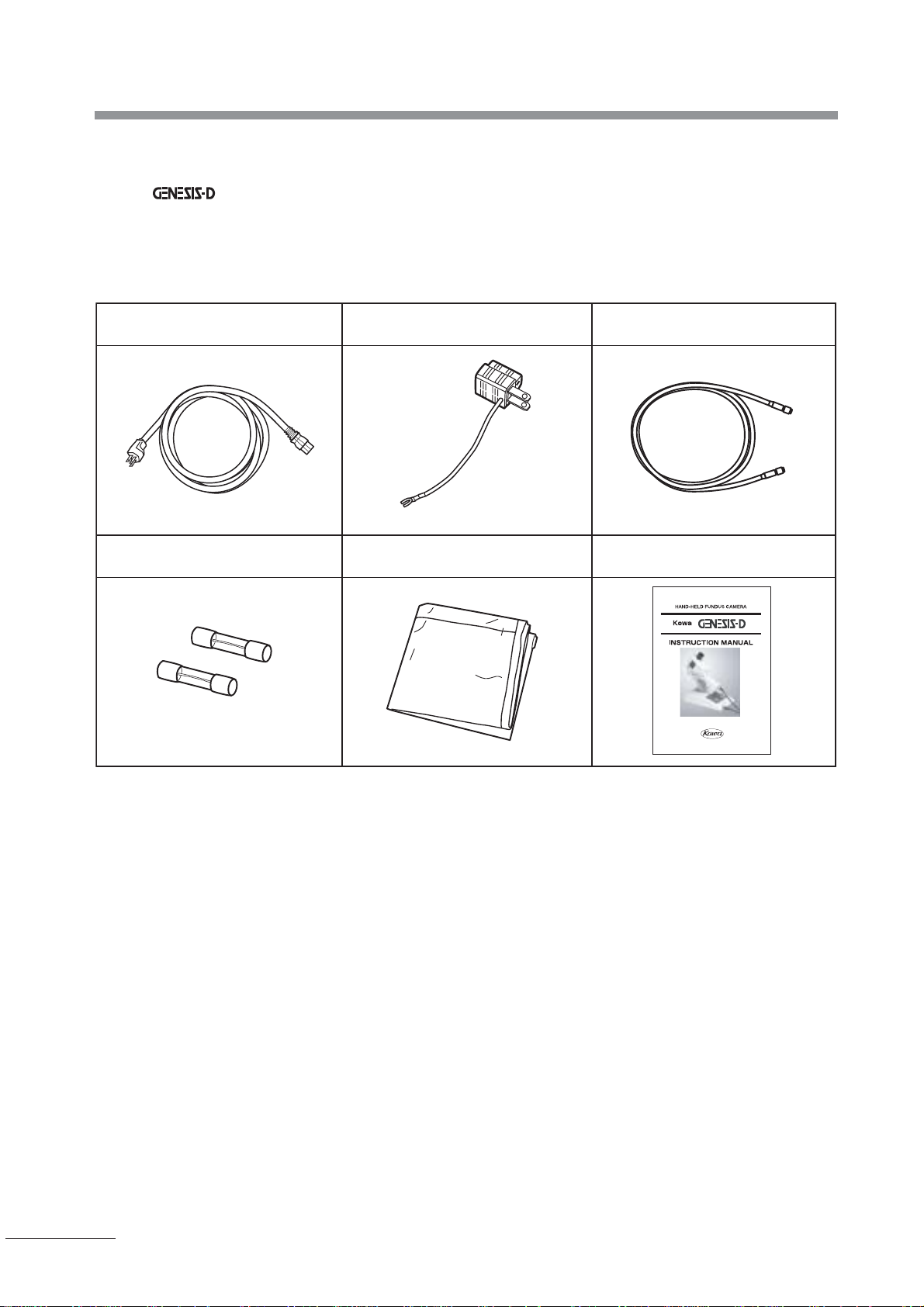
ACCESSORIES
Power cable: 1 pc. 3-pin plug: 1 pc. Connector cable: 1pc
Fuse: 2 pc Dust protective cover: 1 pc Instruction manual: 1 pc.
P - 6
Page 8

Contents
• Introduction....................................................................................................... 1
• Operational Considerations for Safety and Accident Prevention................ 1
• OPERA TING PRECAUTIONS............................................................................ 4
• Operational Precautions in Use of Hospital Grade Electrical Equipment
of Medical Electrical Equipment (Safety and Accident Prevention) ............ 5
•Outline ................................................................................................................ 6
•Accessories ....................................................................................................... 6
•Contents ............................................................................................................. 7
1. Name and function of each part .................................................................... 8
2. Preparation .................................................................................................... 12
2-1 Connecting................................................................................................. 12
2-2 How to insert / take out Compact Flash memorycard............................ 12
2-3 Initializing Digital Camera......................................................................... 14
2-4 Inputting ID................................................................................................. 16
2-5 Conditioning the examined eye ............................................................... 17
3. Operating procedure of color photography ............................................... 18
3-1 Operating procedure chart ....................................................................... 18
3-2 Adjusting ocular (eyepiece) diopter ........................................................ 19
3-3 Confirming the number of unexposed frames available for
photography............................................................................................... 19
3-4 Inputting ID / Selecting ID ......................................................................... 20
3-5 Confirming the pupil's diameter .............................................................. 20
3-6 How to photograph with the camera ....................................................... 20
3-7 Selecting the flash intensity levels .......................................................... 21
3-8 Positioning the camera with respect to the examined eye
(alignment) ................................................................................................ 22
3-9 Focusing..................................................................................................... 23
3-10 Photographing........................................................................................... 23
3-11 Confirming/deleting the preview.............................................................. 23
3-12 Reconfirming / deleting pictures on LCD monitor screen..................... 24
3-13 How to transfer pictures to PC................................................................. 25
4. Other functions ............................................................................................. 26
4-1 How to delete pictures at a time............................................................... 26
4-2 Display / non-display of ID, date and page on LCD monitor screen ..... 27
4-3 Selecting a desired type of date description .......................................... 28
5. Troubleshooting ............................................................................................ 29
6. Maintenance and inspection........................................................................ 32
6-1 Daily inspection ......................................................................................... 32
6-2 Inspecting / cleaning objective lens and light projecting prism ........... 33
6-3 Cleaning / disinfecting the forehead rest ................................................ 33
6-4 Replacing electric flashlight tube by a new one..................................... 33
6-5 Replacing fuse by a new one ................................................................... 35
6-6 Replenishing consumables ...................................................................... 35
6-7 Regular inspection ................................................................ 35
7. Specifications................................................................................................ 36
P - 7
Page 9
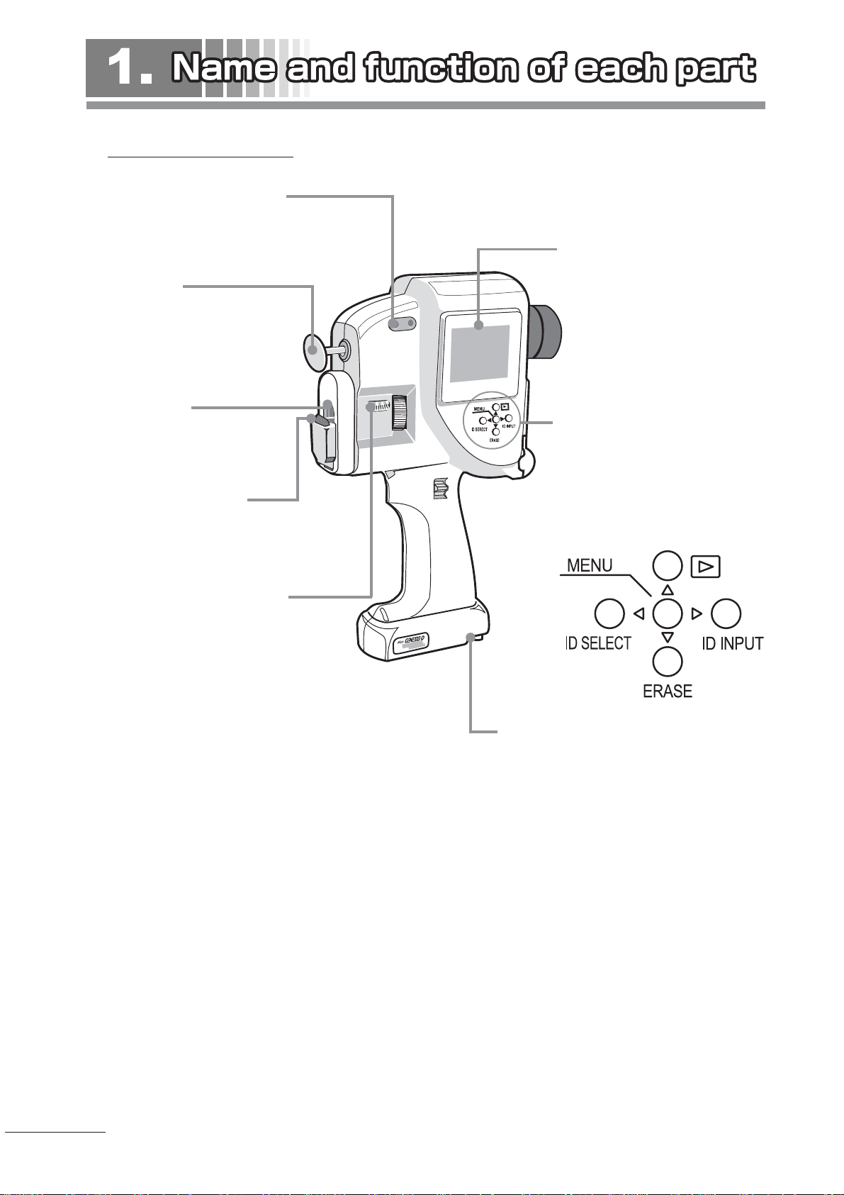
Main unit (camera unit)
Screws for fitting the tripod
Tapped hole for fitting the indirect ophthalmoscope holder
Forehead rest
Spring-type expandable forehead
rest
Objective lens
Lens for photographing the
fundus
Light projecting prism:
For illuminating the examined
eye, from which illumination light
is emitted
LCD monitor screen
On this 2.5-inch size monitor,
desired settings can be selected
for the camera and pictures
taken can be displayed thereon.
Control buttons
-Used for selecting desired settings for the camera and for displaying photographed images
-Five buttons in all: MENU-, UP-,
DOWN-, LEFT-, and RIGHT - buttons.
Examined eye diopter scale:
For indicating the examined
eye's diopter
Cable terminal
(on the bottom surface):
For connecting the power cable
to the power supply unit.
P - 8
Page 10
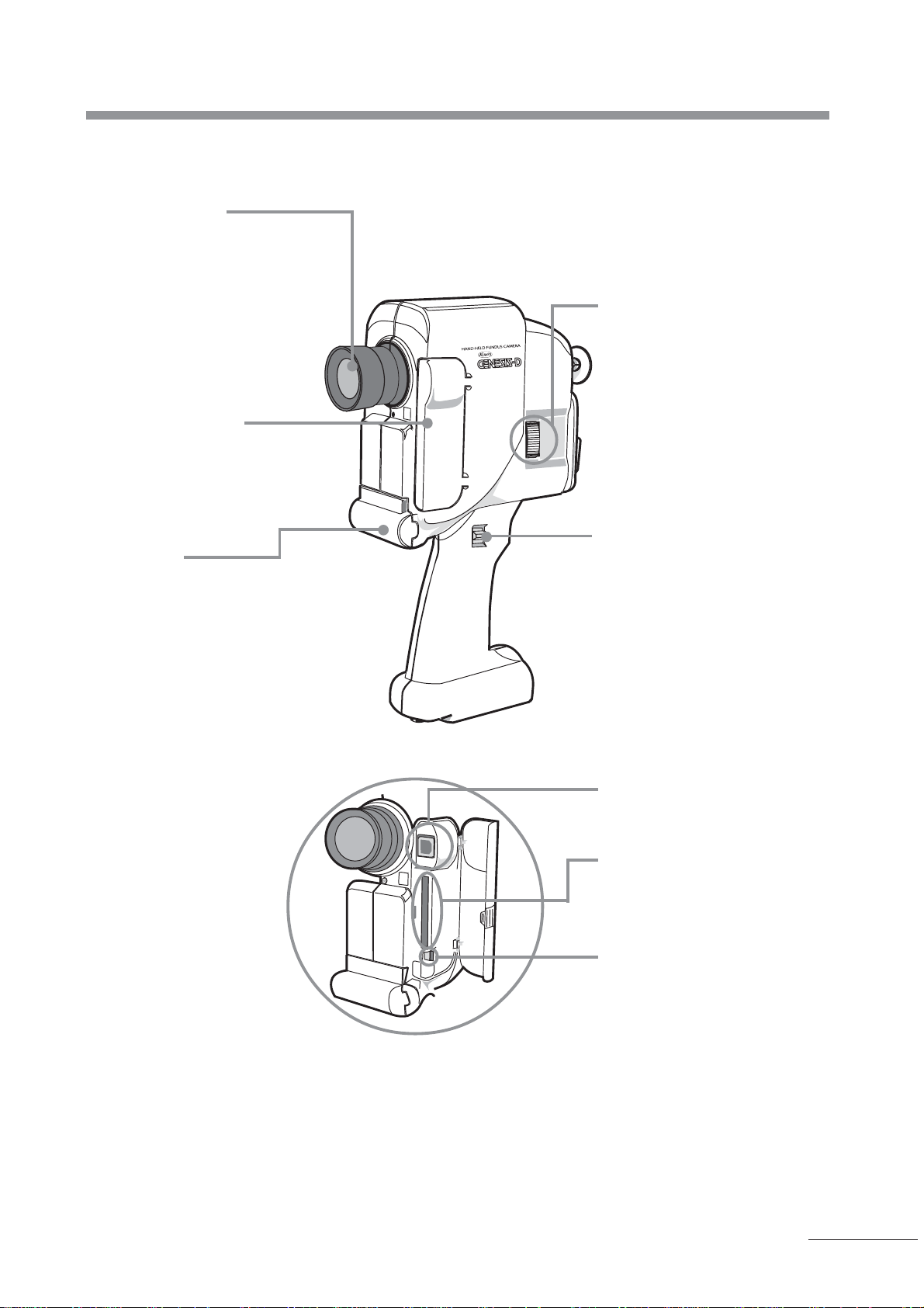
Ocular (eyepiece)
If you wear glasses, turn the
ocular's (eyepiece's) rubber rest
outward. The ocular diopter can
be adjusted in a range of -8 m
(D) to +5 m-1(D) to fit the
examiner's eye. Double-cross
hairs are incorporated for focusing.)
CF protective cover
-For protecting the Compact
Flash memory card
-Open the cover to find Compact
Flash memory card insert slot
and USB terminals.
Light supply
protective cover:
Open this cover when replacing
the flash light tube.
-1
Focus knobs
-Provided on both sides of the
camera unit and are used for focusing.
Shutter switch
-Provided on both sides of the
camera unit
-Slide the switch down
USB terminal
-For connecting the USB cable
Compact Flash memory card
Insert slot
-Opening into which to insert
Compact Flash memory card
Ejector button
-Used for taking out Compact
Flash memory card
P - 9
Page 11
1. Name and function of each part
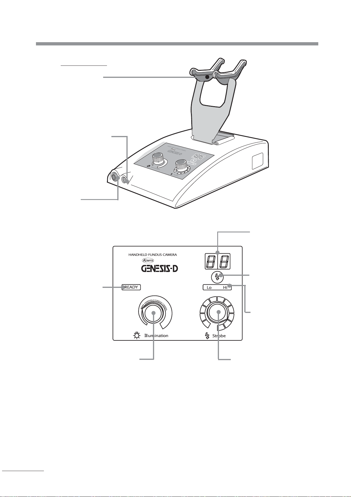
Power supply
Stay
Base on which to mount the camera unit
External shutter terminal
-Terminal for connecting the
optional foot switch
Cable terminal
-Terminal for connecting the
connector cable to the camera
unit
READY indicator light
-Will come ON when the
camera becomes ready
to photograph,
Illumination light intensity
selector knob
-for adjusting the illumination
light intensity
Control panel
Flash light intensity
indicator
-For indicating the current flash light intensity
Hi / Lo selector switch
-For selecting Hi or Lo
level of light intensity
for photography
Hi / Lo indicator light
-For indicating the current light intensity for
photography
Flash light intensity selector
knob
-Used for adjusting the flash
light intensity for photography
P - 10
Page 12
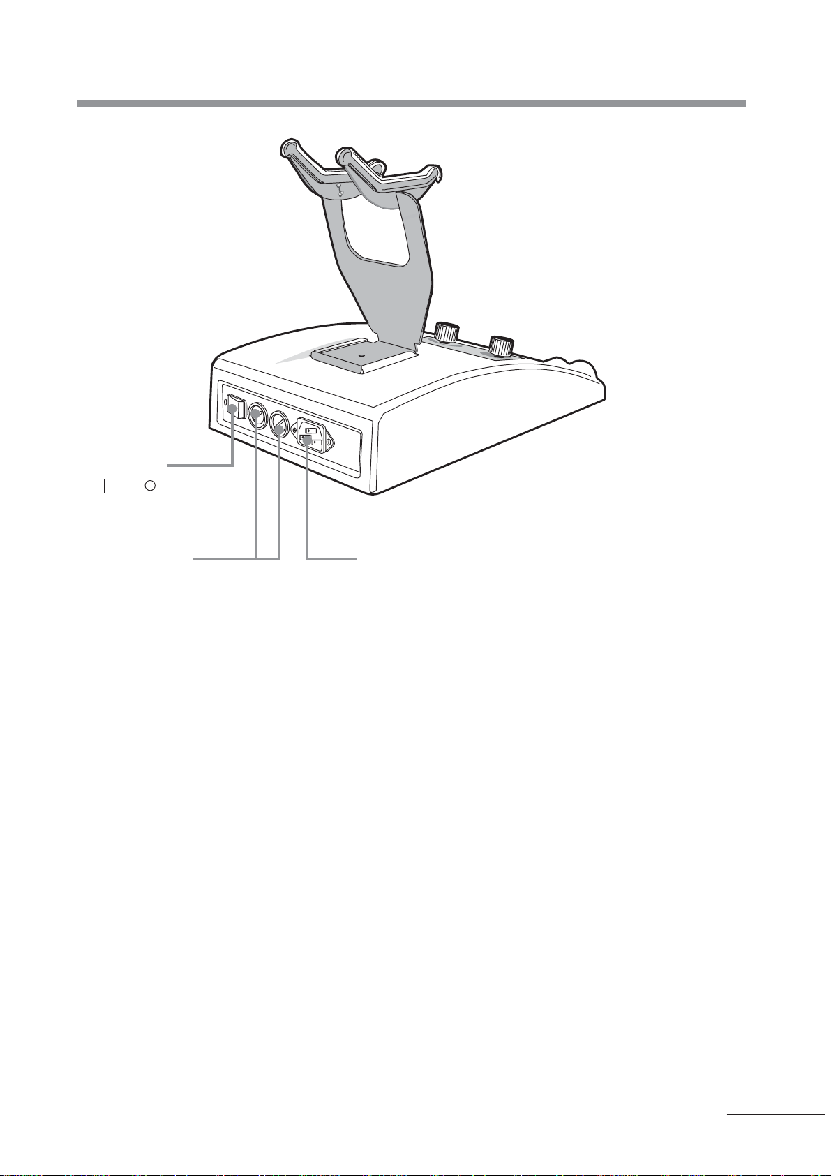
Power switch
- : ON / : OFF indicated on the switch
Fuse holder
-Holder in which to fit the fuse
AC inlet
-To which the accessory power cable is
connected
P - 11
Page 13

2-1 Connecting
1 Place the power supply on a stable table and then connect the power cable to the power inlet in the rear of power
supply unit and the wall outlet.
2 Fit the stay to the power supply unit.
3 Mount the camera unit on the stay and then connect the connector cable to the camera unit and the cable terminal of
the power supply unit.
2-2 How to insert / take out Compact Flash memory card
2-2-1 How to take out Compact Flash memory card from the camera unit
1 Open CF card protective cover on the camera unit.
2 Insert Compact Flash memory card into the slot to its full depth with good care about the direction in which it is to be put
into the slot.
3 Make sure the ejector button will project. (If the card is improperly inserted, the ejector button will not project properly.)
4 Close the CF card protective cover.
Be careful of
the direction
witch put in
a CF card
Ejector
button
P - 12
Page 14

2-2 How to insert/take out Compact Flash memory card
2-2-2 How to take out Compact Flash memory card from the camera unit
1 Make sure that "READY" indicator light is ON or that the power supply is OFF.
2 Open the CF protective cover.
3 To push in the ejector button will cause the Compact Flash memory card to project. Pull out the Compact Flash memory
card from the camera unit with its protruded portion being held by your fingers.
●When the power supply is ON and "READY" lamp is OFF, never pull out the Compact Flash memory card nor turn
OFF the power supply with the card held in the slot. Otherwise the CF memory card's data may be destroyed.
●When the power supply is ON, never pull it out from the slot immediately after inserting Compact Flash memory
card therein. Otherwise, next time Compact Flash memory card is inserted, "No Compact Flash" message will
nevertheless remain on the monitor screen. In this case, it is necessary to turn OFF the power supply and then
turn it ON again.
P - 13
Page 15

2. Preparation
2-3 Initializing the camera
2-3-1 Setting date / time
1 Open CF card protective cover and insert Compact Flash memory card into the slot.
2 Turn ON the power switch in the rear of power supply unit and then make sure the power supply's "READY" indicator light
will come ON. (After turning ON the power switch, it will take some time for "READY" indicator light to come ON.)
3 Press MENU button to switch the LCD monitor screen to MAIN MENU where READY indicator light is OFF.
4 With
made to point at SETUP by / buttons, press MENU button to switch to SETUP screen.
5 With made to point at DA TE / TIME by / buttons, press MENU button to switch to DATE / TIME screen.
6 Move
buttons.
7 After DATE / TIME change is complete, press MENU button to switch back to SETUP screen. On this screen, with
made to point at END by / buttons, press MENU button to switch back to "READY" display. Now, DATE / TIME is
complete.
by / buttons as far as either of them can point at a desired item and then change DATE / TIME by /
Range of DATE / TIME settings enabled on display screen
Y :Denotes the Christian era which can be set in a range of 2000 to 2099.
M:Denotes the month which can be set in a range of 01 to 12.
D :Denotes the day which can be set in a range of 01 to 31.
h :Denotes the time in terms of 24-hour designations which can be set in a range of 00 to 23.
m:Denotes the minute which can be set in a range of 00 to 59.
P - 14
Page 16

2-3-2 Changing the quality level of picture stored
1 Press MENU button to switch LCD monitor screen to MAIN MENU display screen.
2 With "
3 With "
" made to point at SETUP by / buttons, press MENU button to switch to SETUP display screen.
" made to point at QUALITY by / buttons, press MENU button to switch to QUALITY display screen
2-3 Initializing the camera
4 With "
" made to point at a desired quality by / buttons, press MENU button to finalize it.
: (Initial quality is NORMAL. A higher quality needs a longer recording time. See approximations of average picture record
size and average record time in terms of picture quality in the table below.
Number of unexposed frames for photography
NORMAL(97/97)
Number of unexposed frames for photography
(The number will decrease as you go on to photograph.)
Maximum number of pictures recorded
(The number of pictures recorded will vary depending on the capacity of
Compact Flash memory card.)
NORMAL Ordinary picture quality
FINE High picture quality mode
RAW DATA Non-compressed data: Pictures are recorded in bit-mapping.
Approximations of record size and record time in terms of quality level of picture stored
Quality of image Data form
Average
recorded time
*1
Capacity of Compact Flash memory
(The values indicated are rough approximate.)
32MB 64MB 128MB 256MB
NORMAL (Standard) JPEG 2 seconds 100 frames 200 frames 400 frames 512 frames
FINE
(high picture quality)
JPEG 4 seconds 50 frames 100 frames 200 frames 400 frames
*2
RAW DA T A
(non-compressed)
Bit mapping 15 seconds 5 frames 11 frames 22 frames 44 frames
*1 The recording time changes slightly depending on recorded objects.
*2 The maximum number of files this camera unit can record is 512 regardless of the capacity of the card.
■ This camera unit corresponds to Compact Flash memory card TYPE I of no more than 256 megabytes, not to the
same type of memory card exceeding this capacity nor to Compact Flash memory card TYPE II.
■ This camera unit is not compatible with FAT32 format. “ERR:WRONG FORMAT” will be displayed on LCD monitor
screen if Compact Flash Memory card formatted in FAT32 format is used for this camera unit. Use a Compact
Flash Memory card after reformatting it in FAT by Windows XP etc.
5 After the picture quality change is complete, press MENU button to switch back to SETUP screen. On this screen, with
made to point at END by / buttons, press MENU button to switch back to "READY" display, now picture quality
change is complete.
P - 15
Page 17

2. Preparation
2-4 Inputting ID
The camera unit is capable of registering no less than ten 5-digit IDs collectively. These registered IDs will be erased when
the power supply is turned OFF.
1 Press MENU button to switch LCD monitor screen to MAIN MENU display screen.
2 With
3 With
made to point at ID by / buttons, press MENU button to switch to ID display screen.
made to point at INPUT by / buttons, press MENU button to switch to INPUT ID display screen.
4 Make sure
5 For registering the first ID, after assuring it is No:01, shift the digit position one after another to change to a constituent
digit in each digit position by
6 When registering the second ID in succession, with
switch to No: 02. Then, in the same manner as in 5, change to constituent digits. For registering the third and later IDs,
repeat the same steps.
7 To end the registration of ID, press MENU button, and with
button to switch to "READY" display again. Now ID entry is complete. (The ID appearing on this display screen is the one
that was established when OK was selected. )
is located on the left-hand side of No: ❇ ❇ and then press MENU button to display .
/ buttons.
made to point at No. 01 by / buttons, press / button to
being made to point at OK by / buttons, press MENU
Short cut to INPUT ID display screen
● To take a short cut to "INPUT ID" display screen, press
" button on the PREVIEW or "READY" display
"
screen.
P - 16
Page 18

2-5 Conditioning the examined eye
2-5 Conditioning the examined eye
1 Before examination, apply mydriatic (drop) to the examined eye. After the pupil of the eye is sufficiently dilated, guide the
patient to the photography room.
2 Make sure the pupil reaches satisfactory dilation level. To get an sufficiently bright picture, it is recommended that the
dilated pupil has a diameter of 8 mm or more.
P - 17
Page 19

3-1 Operation procedure chart
Adjustment ocular (eyepiece) diopter
Confirmation of unexposed frames for photography
Inputting ID / Selecting ID
Confirmation of pupil's diameter
Selection of flash light intensity
Positioning the examined eye with respect to the camera
(alignment)
Focusing
Photography
Confirming / Deleting preview
Reconfirming / deleting on LCD monitor
P - 18
Transfering pictures to PC
Page 20

3-2 Adjusting ocular (eyepiece) diopter
After turning it counterclockwise to a full scale on the + side, slowly turn the diopter adjust ring clockwise. When reticle comes
in clear sight, then stop turning it. If the diopter has been improperly selected, pictures will become out of focus. If you wear
glasses, turn the ocular's (eyepiece's) rubber rest outward.
Out of focus In focus
Make sure the ocular's diopter is properly set.
If not, pictures may become out of focus.
3-3 Confirming the number of unexposed frames available for photography
1 Open the CF memory card protective cover to insert Compact Flash memory card.
2 Turn ON the power switch in the rear of the power supply unit, and make sure that "READY" indicator light on the
power supply unit is ON. (After turning ON the power switch, it takes some time for the READY indicator light to come
ON.)
3 The number of unexposed frames remaining for photography is indicated on the upper left-hand side of LCD monitor
screen. Make sure a sufficient number of unexposed frames remain for photography.
(You can replace Compact Flash memory card by a fresh one. When replacing the card with the power supply ON,
make sure READY indicator light on the power supply unit is ON before replacement. For the steps of inserting/taking
out Compact Flash memory card, see "2-2 Inserting/Taking out Compact Flash memory card."
The number of
remined
frames.
P - 19
Page 21

3. Operating procedures in color photography
3-4 Inputting ID / Selecting ID
If you have not entered your ID beforehand, see "2-4 Inputting ID."
1 Press MENU button to switch the LCD monitor screen to MAIN MENU display screen.
2 With
3 With made to point at SELECT by / button, press MENU button to switch to SELECT ID display screen.
4 Press / buttons to point at a desired patient's ID from those which have been entered beforehand. When MENU
button then is pressed , the ID will be decided, switching back to. "READY" display screen. Now ID selection is
complete.
made to point at ID by / buttons, press MENU button to switch to ID display screen.
Shortcut to SELECT ID display screen
● To take a shortcut to SELECT ID display screen,
press
screen.
button on PREVIEW or "READY" display
3-5 Confirming the pupil's diameter
Make sure the examined eye's pupil is sufficiently dilated.
3-6 How to photograph with the camera
You can operate the camera with either your right or left hand. Firmly hold the camera's grip by your hand such that the
shutter switch can be placed on the thumb and the focus knob on the forefinger.
P - 20
Page 22

3-7 Selecting the flash light intensity
3-7 Selecting the flash light intensity
● On this camera unit, 28 levels of flash light intensity are available for selection.
● The flash light intensity will be indicated on the flash light intensity indicator. Normally, the flash light intensity will be
set to NORMAL (level 6).
● If there is a need to correct the amount of exposure based on the dilation level of examined eye's pupil and the density
of reflected light from the retina, you can select a desired level of flash light intensity by the flash light intensity select
knob on the power supply unit.
● If the amount of exposure cannot be corrected by the knob only, push Hi / Lo select switch of the power supply unit to
switch to "Hi" level of the Hi / Lo indicator light. Now a higher level of exposure (Levels 8 to 19) is available.
● On the other hand, the amount of exposure is too large, press the Hi / Lo select switch to disable the Hi / Lo indicator
light. Now a smaller amount of exposure (Levels 0.1 to 0.9) is available.
Hi / Lo Flash light intensity Fundus
indicator light indicated photography (std.)
Disabled 0.1
Disabled 0.2
Disabled 0.3
Disabled 0.4
Disabled 0.5
Disabled 0.6
Disabled 0.7
Disabled 0.8
Disabled 0.9
Lo 1
Lo 2
Lo 3
Lo 4
Lo 5
Lo 6 Subject for photography
Lo 7
Lo or Hi indicated 8
Lo or Hi indicated 9
Lo or Hi indicated 10
Lo or Hi indicated 11
Lo or Hi indicated 12
Hi 13
Hi 14
* It is assumed that an image of anterior segment is approximately 4
times its real size. Set the focus knob on the camera unit at +15D
and the distance between the examined eye and the camera unit at
7 cm. When a higher magnifying power is applied in photography,
turn the focus knob incrementally to the (+) side so that the
camera unit can be as close to the examined eye as practicable.
Anterior segment photography standard.*
Each time you press the Hi / Lo
select switch, neither Hi nor Lo will
be indicated on the Hi / Lo indicator light.
Disabled
Lo
Hi
For illumiation and photography, do not select any higher exposure than it is required
Otherwise, the examined eye may suffer a pain or disorder.
P - 21
Page 23

3. Operating procedures in color photography
3-8 Positioning the camera with respect to the examined eye (alignment)
In fundus photography, it is necessary to guide an amount of exposure necessary for photography to the fundus through the
pupil. Therefore, the location of camera with respect to the examined eye is limited.
1 Set the illumination lamp intensity select knob of the power supply unit pointing at 10 o'clock (position of "K" as in
KOWA indicated along the periphery).
2 Adjust its position while looking at the examined eye from the side of the camera unit with the forehead being set
against the forehead rest such that the examined eye is about 5 mm away from the light projecting prism.
3 Looking at the examined eye from the side of the camera unit, make sure the illuminated image can be formed on the
cornea of the examined eye.
4 Looking into the ocular, fine-adjust the position of the camera unit with respect to the examined eye such that illumi-
nation light is uniformly guided into the fundus to prevent a formed image from getting out of focus.
NG In focus in the right-hand half
while out of focus in the left-hand
half.
Operate the fundus camera with good care such that patient's eye, nose and face do not touch any part of
the camera other than the forehead rest.
OK In focus around the periphery of
image
P - 22
Page 24

3-9 Focusing
3-10 Photograping
3-11 Confirming/deleting the preview
3-9 Focusing
Looking into the ocular, turn the knob upward and downward so that reticle and targeted part of fundus each can be in focus.
(Looking into the ocular, check an image for its brightness. If improper, compensate it by adjusting the brightness by the
illumination lamp intensity select knob.)
Scale
Focus knob
NG Reticle is in focus but image of
fundus is out of focus.
The scale on the cover on the left-hand side of the camera unit indicates the examined eye's diopter. When
photographing the anterior segment, set a focus on the (+) side beforehand and then fine-adjust it on the (-) side
until a subject for photography is in focus.
OK Reticle and image of fundus
each are in focus.
3-10 Photograping
Photography is enabled by pressing the shutter switch downward. (Note that the shutter switch will operate only when
pressing it downward, instead of pressing it in or upward.)
● To maintain the shutter switch pressed downward will enable continuous photography. But when an image is
being recorded on the camera, the shutter will not click (prohibiting photography). (For the amount of time required
to record an image, see "2. Preparation 2-3-2 Changing the quality level of picture recorded.")
● When the optional foot switch is connected to the camera unit, the shutter will click by either the shutter switch on
the camera unit or the optional foot switch.
The shutter will not click when READY indicator light is OFF, more specifically while the menu display is ON, USB
terminal is in connection, or recorded images are being reconfirmed in PLAY mode.
3-11 Confirming/deleting the preview
Immediately after a picture was taken, it can be displayed on the LCD monitor screen for your confirmation.
1 When a picture is taken, it will be displayed on the LCD monitor screen on the camera unit simultaneously.
2 To delete a picture after confirmation, press ERASE button with the picture being displayed on the LCD monitor
screen.
3 A message "ERASE OK?" appears on the picture on the LCD monitor screen. For deletion, press MENU button on
the camera unit. To cancel deletion, press either "
4 When deletion is complete, LCD monitor screen will be switched to "READY" display. If deletion is canceled, it will be
changed to the display as in 1.
" button or " " button.
P - 23
Page 25

3. Operating procedures in color photography
3-12 Reconfirming/deleting pictures on LCD monitor screen
A picture taken can be reconfirmed on the LCD monitor screen on the camera unit.
When reproduced, the pictures are shown in an ascending order of dates photographed.
You can also delete the pictures one by one from PLAY display screen.
(To delete pictures collectively, see "4-1 How to delete pictures at a time.")
1 Press MENU button to switch the LCD monitor screen to MAIN MENU display screen.
2 To select PLAY, press MENU button by pressing
screen to PLA Y display screen.
3 Select pictures by / buttons.
(A preceding picture is displayed by button and the next one by button.)
4 To delete a picture taken, press ERASE button with the picture being displayed on the LCD monitor screen.
5 A message "ERASE OK?" appears on the picture on the LCD monitor screen. For deletion, press MENU button. To
cancel deletion, press either
6 To exit Play display screen, press MENU button to switch to READY display screen.
or button.
/ buttons to make point at PLAY, to switch the LCD monitor
P - 24
Shortcut to PLAY display screen
● To take a shortcut to PLAY display screen, press
( ) button when you are confirming the
PREVIEW or on Ready display screen.
Page 26

3-13 How to transfer pictures to PC
3-13 How to transfer pictures to PC
There are two ways to transfer pictures to PC.
● One method is to take out Compact Flash memory card, and then transfer recorded pictures to PC via a commercially
available Compact Flash memory card reader or adapter connected to PC.
● The other method is to connect the camera unit to PC by USB cable and transfer the image in Compact Flash
memory card to PC.
This paragraph describes how to connect the camera unit to PC by USB cable.
3-13-1 How to connect the camera unit to PC by USB cable.
This camera unit can serve as Compact Flash memory card reader if it is connected to PC via USB cable (separately
and commercially available as accessory).
Operating system installed on PC connected to this camera unit is Windows ME / 2000 / XP.
(If your PC has a different type of operating system, it is recommendable to see "2-2 How to insert/take out Compact
Flash memory card" and use commercially available Compact Flash memory card or adapter.
1 Make sure READY indicator light on the power supply unit is ON.
2 Open CF memory card protective cover on the camera unit.
3 Connect one end of commercially available USB cable (Type A-B) to USB terminal of the camera unit and the other
end thereof to PC. (READY indicator light is OFF at this stage.)
4 A message "USB Connected" appears on the LCD monitor screen and a new removable disk is recognized on the
PC. (This will be installed on PC automatically .)
3-13-2 File Name
The file name is managed in 8-digit numbers.
.jpg
: The first 5-digit section denotes ID number.
: The last 3-digit section denotes a serial picture number under the ID above.
Example:
The file Name 12345012.jpg denotes a picture with serial picture number 12 of a patient with ID 12345.
P - 25
Page 27

4-1 How to delete pictures at a time
1 Make sure READY indicator light on the power supply unit is ON.
2 Press MENU button to switch the LCD monitor screen to MAIN MENU display screen.
3 With
made to point at ERASE by / buttons, press MENU button to switch to ERASE display screen.
4 With
5 A message "ERASE OK?" appears on the display screen. To delete the picture, maintain MENU button pressed at
least one second. (After a message "Deleted" appears on the display screen, automatically READY display screen
appears again.)
To cancel deletion, press
If you delete a number of pictures collectively, the more pictures in Compact Flash memory card, the longer time it will
take to do so.
The deleted number of pictures cannot be returned.Be fully careful when you delete files.
made to point at ALL or FORMAT by / buttons, press MENU button.
or button to bring the display back to ERASE display screen.
ALL and FORMAT
ALL : Used to delete all pictures with IDs which have been currently selected
FORMAT : Used to delete all pictures in Compact Flash memory card regardless of what IDs are currently
selected
END : Used exit ERASE display screen if you cancel deletion.
P - 26
Page 28

lay of PAGE
4-2 Display / non-display of ID, date and page on LCD monitor screen
To display pictures on the LCD monitor screen (review / reproduction), select display / non-display of ID, date and page.
IDIDID
1 Make sure READY indicator light on the power supply unit is ON.
2 Press MENU button to switch the LCD monitor screen to MAIN MENU display screen.
3 With
made to point at SETUP by / buttons, press MENU button to switch to SETUP display screen.
4 With
5 With
6 After settings are complete, press MENU button to switch back to SETUP button.
7 With
exit.
made to point at DISPLAY by / button, press MENU button to switch to DISPLAY screen.
made to point at ID, DATE / TIME, PAGE by / buttons, press / buttons. to select ON / OFF.
made to point at END by / buttons, press MENU button to switch back to READY display screen and
P - 27
Page 29

4. Other functions
4-3 Selecting a desired type of date description
The camera unit has three types of date descriptions: "Year / Month / Day," "Month / Day / Year," and "Day / Month / Year."
This paragraph describes how to change the type of date description. The initial date description is set to "Year / Month /
Day."
1 Make sure READY indicator light on the power supply unit is ON.
2 Press MENU button to switch the LCD monitor screen on the camera unit to MAIN MENU display screen.
3 With
4 With
5 Press
6 Press MENU button to switch to SETUP display screen.
7 With
made to point at SETUP by / buttons, press MENU button to switch to SETUP display screen.
made to point at DATE FORM by / buttons, press MENU button to switch to DATE FORM.
/ buttons to make point at a desired type of description.
made to point at END by / buttons, press MENU button to switch to READY display screen.
P - 28
Page 30

This paragraph describes a remedy when abnormality occurs on the camera unit. In case any abnormality should occur on
the camera unit, check the following before you contact your dealer where you purchased it.
Be sure to turn OFF the power supply before repair.
Trouble Description of trouble Remedy
MENU display screen has been selected
on the LCD monitor screen.
Exit MENU display screen by control
button to switch to READY display
screen.
To press the shutter switch will not
cause the shutter to click.
Connector cable is improperly connected
Compact Flash memory card has not
been inserted in the slot.
No unexposed frame remains on the Compact Flash memory card
Shutter switch has been pressed in or
upward.
Message "BUSY" appears on the LCD
monitor screen.
USB cable has been in connection.
Connect the connector cable properly.
Insert Compact Flash memory card.
See "2-2 How to insert/take out Compact Flash memory card"
Replace Compact Flash memory card
by a fresh one or delete unwanted pictures from it.
See "3-12 Reconfirming/deleting pictures on LCD monitor screen" and "4-1
How to delete pictures at a time."
To press in or press upward the shutter
switch will disable shutter-clicking.
Pressing downward only will enable
shutter-clicking.
A preceding picture is being recorded.
Wait till the message "BUSY" comes
OFF.
Recording time will vary depending on
which quality of picture (to be saved) you
select.
See "2-3-2 Changing the quality level of
picture recorded"
Remove USB cable.
READY indicator light is OFF.
READY indicator light is OFF.
MENU display screen has been selected
on the LCD monitor screen.
Connector cable is improperly connected
Compact Flash memory card has not
been inserted in the slot.
No unexposed frame remains on the Compact Flash memory card
See "READY indicator light is OFF" described below.
Exit MENU display screen by control
button to switch to READY display
screen.
Connect the connector cable properly.
Insert Compact Flash memory card.
See "2-2 How to insert/take out Compact Flash memory card"
Replace Compact Flash memory card
by a fresh one or delete unwanted pictures from it.
See "3-12 Reconfirming/deleting pictures on LCD monitor screen" and "4-1
How to delete pictures at a time."
P - 29
Page 31

5. T roubleshooting
Trouble Description of trouble Remedy
READY indicator light is OFF.
Message "BUSY" appears on the LCD
monitor screen.
A preceding picture is being recorded.
Wait till the message "BUSY" comes
OFF.
Recording time will vary depending on
which quality of picture (to be saved) you
select.
See "2-3-2 Changing the quality level of
picture recorded"
Flash lamp for photography
does not come ON.
Illumination lamp will not come
ON.
When looking into the ocular,
nothing is seen.
A shadow of white dot appears
in the identical location in a series of pictures taken.
USB cable has been in connection.
Flash lamp is improperly fitted.
The flash lamp is clouded in white.
The fuse has run out.
Flash light intensity indicator on the
power supply unit is set to 0.1.
LED unit is improperly mounted.
Lens is covered by lens protective cap.
Dust deposits on the objective lens.
Objective lens is fould by tear etc.
Examined eye's eyelashes are in the
way .
Remove USB cable.
Properly fit the flash lamp.
See "6. Maintenance and inspection."
Replace the flash lamp by a new one.
See "6. Maintenance and inspection."
Raplace the fuse by a new one. See "6.
Maintenance and inspection."
If the value is set to of 0.1, the amount
of exposure is so low that the flash light
may look as if emitting no light.
Set a proper amount of exposure for
photography .
Properly mount LED unit.
See "6. Maintenance and inspection."
Remove the cap.
Clean the objective lens.
See "6.Maintenance and inspection."
Clean the objective lens.
See "6.Maintenance and inspection."
Keep eyelashes out of the way in the
pupil.
P - 30
Upper part of picture taken
darkens.
Lower part of picture taken
darkens.
A shadow of dark dot appears
in the identical location in a series of pictures taken.
ID does not appear on the LCD
monitor screen.
Light projecting prism is fouled.
The camera unit is located too away from
the examined eye.
The camera is too close to the examined eye.
Dust deposits inside of the camera.
Neither PREVIEW nor PLAY display
screen has been selected.
ID/OFF has been selected from DISPLA Y items on the SETUP display.
Clean the light projecting prism.
See "6. Maintenance and inspection."
Re-align the fundus camera properly
with respect to the examined eye.
Re-align the fundus camera properly
with respect to the examined eye.
Contact your dealer where you purchased it for cleaning.
ID will be indicated on -PREVIEW or
PLA Y display screen only.
Select ID/ON from DISPLA Y items on the
SETU display Instead.
Page 32

Trouble Description of trouble Remedy
Page will not be indicated on
PLAY display.
DA TE will not be indicated on the
LCD monitor screen.
Picture taken will not be displayed
in proper (ascending) order on
PLA Y display screen.
Flash light intensity is indicated
in “Cd” on the power supply unit.
“ERR:WRONG FORMA T” will be
displayed on LCD monitor
screen.
PLAY display has been selected.
PAGE / OFF has been selected from DISPLAY items on SETUP display screen.
Neither PREVIEW nor PLAY display has
been selected.
DA TE / TIME-OFF has been selected from
DISPLAY items on the SETUP display
screen.
Date and time has not been properly set.
Connector cable has been disconnected.
Compact Flash Memory card is formatted in FAT32 format.
PAGE will be indicated on PLAY display
only.
Select PAGE / ON from DISPLAY items
on the SETUP display screen instead.
ID will be indicated on PREVIEW or
PLAY display screen only.
Select DATE / TIME-ON from DISPLAY
items on the SETUP display screen instead.
On PLAY display, pictures taken will be
displayed in an ascending order of date/
time photographed.
If wrong date and time were entered, they
will not be displayed in right serial order.
Set correct date from DATE / TIME items
on the SETUP display screen.
Connect the connector cable.
This camera unit is not compatible with
FAT32 format. Use a Compact Flash
Memory card after reformatting it in FAT
by Windows XP etc.
“No Compact Flash” is displayed
on the LCD monitor screen.
“Card is full” is displayed on the
LCD monitor screen.
“ERR:Root is full” is displayed on
the LCD monitor screen.
“ERR:Broken File” is displayed on
the LCD monitor screen.
“ERR:Cannot Decode” is displayed on the LCD monitor
screen.
The Compact Flash is not inserted correctly.
The remaining number of files which can
be recorded is 0.
The number of files in the Compact Flash
is over 512.
The Compact Flash is removed or the
camera power is turned off when the
READY indicator light is off while the camera power is on.
Files recorded by a camera other than this
camera unit are contained in the Compact
Flash.
Insert a Compact Flash card correctly.
Delete unnecessary files or insert another Compact Flash which is not full.
Delete unnecessary files or insert another Compact Flash which is not full.
Files may be damaged if Compact Flash
is removed or the camera power is turned
off when the READY indicator light is off
while the camera power is on. Keep in
mind that the damaged files cannot be
recovered.
Delete the files recorded by a camera
other than this camera unit, or format the
Compact Flash. If this still does not solve
the problem, the Compact Flash may be
damaged. Replace the Compact Flash
with a new one.
P - 31
Page 33

Because fundus camera is a precision instrument, picture quality may depend on how well your daily maintenance and
inspection have been conducted. To use the product properly and safely, it is recommendable to read these items carefully.
6-1 Daily inspection
1) After photography is complete, be sure to turn OFF the power switch and replace the objective lens cap.
2) Care must be used to protect the objective lens and the light projecting prism against dust, fingerprints, teardrops and so
on.
Be sure to check objective lens and light projecting prism for any foul before starting photography for the day.
3) If fouled, clean camera unit, power supply unit and forehead rest with soft cloth. If stubbornly fouled, apply diluted neutral
detergent to them. If applied to them, chemical or solvent such as thinner and benzene will degrade, deform the objective
lens and light projecting prism or peel off their paint.
1 Wipe off their exterior with soft cloth which was moistened with water and whose moisture was then tightly squeezed
off.
2 Softly wipe off the LCD monitor screen with soft cloth like gauze because it is liable to suffer damage.
3 If stubbornly fouled, wipe it off with soft cloth which was moistened with neutral detergent diluted by water or luke-
warm water and whose moisture was then tightly squeezed off.
4) If there is no need to use the fundus camera for a long period of time, keep the power cable unplugged from the wall
outlet.
● If all of a sudden, the fundus camera that has been stored in a cool room should be moved to a warm room, the
objective lens or other internal lens .may be misted. In this case, allow some time for mist to disappear from them.
Otherwise, pictures taken may be out of focus.
● If lens is repeatedly misted, it may become moldy. In this case, contact your dealer where you purchased the
fundus camera for overhaul.
Do not wipe off the exterior of the fundus camera with solvent such as benzene, alcohol, thinner and ether
that may cause discoloration and deformation.
P - 32
Page 34

6-2 Inspecting/cleaning objective lens and light projecting prism
A shadow of white maybe reflected to the same place of the picture when objective lens and light projecting prism were dirty
with the fingerprint. Clean a lens in the following procedure.
1 Lightly wipe in a circular motion the objective lens and light projecting prism from their center little by little to their outer
side using cotton swab slightly moistened with a mixture (1:1) of absolute alcohol and ether.
2 If even the dirt should resist the mixture, you may do the job by slightly wiping them around with a cotton swab slightly
moistened this time with water.
After going through these steps, thoroughly wipe them again with this mixture. For stubborn dirt still existing on them,
contact your dealer where you purchased the fundus camera.
● If the objective lens should be wiped hard with dust depositing on it, it may suffer damage.
● Do not use chamois leather or silicone cloth.
● Be very careful about handling the mixture because it is liable to evaporate or catch fire.
6-3 Cleaning/disinfecting the forehead rest
Every time photography is complete for one patient, lightly wipe the forehead rest with soft cloth slightly moistened with ether
beforehand for photography of another patient to come.
6-4 Replacing electric flashlight tube by a new one
1 Unplug the power cable from the wall outlet with the power supply OFF.
P - 33
Page 35

6. Maintenance and inspection
Screws
Connector
Connector
Screws
2 For removal, loosen screws for fitting the light supply protective cover by screw driver.
3 Remove the connector and then loosen screws of two places indicated in drawing by
unit.
4 Flash lamp unit will come into sight. Loosen screws of two places by
the connector.
Connector
Connector
Screws
Screws
Screws
6-4 Replacing electric flashlight tube by a new one
screw driver indicated in drawing to remove
screw driver to remove LED
Screws
Screws
Connector
Connector
5 Connect the connector to a new flash lamp unit and fit it by
careful about the direction in which it is to be fitted.
6 Fit LED unit which was removed in 3, by
to it.
7 Mount the light source unit and then tight-screw it.
● Remove and fit the connectors of the flash lamp unit and LED unit in a straight line.
● Push in the connectors of the flash lamp unit and LED unit to their full depth.
● When fitting flash lamp unit, LED unit and light source protective cover, care must be used not to get their
connector cables pinched in between.
● Care must be used not to touch the flash lamp with bare hand. Otherwise, greasy substance on your finger may
transfer to the surface of the lamp, which will burn by heat resulting in a shorter service life.
screw driver in reverse order of removal and then connect the connector
screw driver in reverse order of removal while being
P - 34
Before replacing flash lamp unit, turn OFF the power switch and remove unplug the power cable from the
wall outlet to avoid electrical shock.
Do not replace Flash lamp unit immediately after use.
Otherwise, the hot surface of the Flash lamp may burn your finger. Allow at least 30 minutes for the lamp to
cool off before replacement.
Page 36

6-5 Replacing fuse by a new one
1 Plug the power cable from the wall outlet with the power supply OFF.
2 Turn counterclockwise the screws of the fuse holder cover on the power supply unit to take out the fuse.
3 After replacing the fuse, close the fuse holder cover. Confirm the capacity and type indicated on it before fitting.
Before replacing the fuse, turn OFF the power switch and unplug the power cable from the wall outlet to
avoid electrical shock.
Use the designated accessory fuse. Otherwise, there may occur a fire resulting in malfunction.
6-6 Replenishing consumables
Designated order numbers for following items:
Consumables Order number
Flash lamp unit K9L-FU51
Fuse
Dust protective cover K9L51#12
Optional items
Foot switch VK-FS2
Indirect ophthalmoscope holder K9L-LH51
Trunk case
CF card / USB cable set K9L-MC51
6-7 Regular inspection
In order to use this instrument safely for a long time, we recommend that you carry out a regular inspection. Consult
your Kowa dealer where you purchased this instrument for details and cost of the inspection.
Type name
P - 35
Page 37

Angle of field Horizontal 30º / Vertical 25º
Working distance 5 mm (between the top of cornea of examined eye and prism)
Effective dioptic range of focusing -15 m
Range of eyepiece correction -8 m
-1
(D) to +35 m-1 (D)
-1
(D) to +5 m-1 (D)
illumination LED
illumination Xenon flash lamp
Record media Compact Flash memory card (TYPE 1)
Output terminal USB (1.1) terminal (B connector)
(Corresponding operating system: Windows ME / 2000 / XP)
Input voltage 100 - 240 V a.c. (50 Hz / 60 Hz)
Power supply input 60 VA
Electromagnetic compatibility IEC 60601-1-2 (1993)
Dimensions (camera unit) 74.5 mm (W) ✕ 197 mm (D) ✕ 278.5 mm (H)
Weight (camera unit) 1070 grams
Dimensions (power supply unit) 180 mm (W) ✕ 300 mm (D) ✕ 230 mm (H)
Weight (power supply unit) 1930 grams
P - 36
Page 38

No. 4-14, 3-chome, Nihonbashi-Honcho, Chuo-ku, Tokyo 103-8433, Japan
Phone: 81(3) 3279-7331
Facsimile: 81(3) 5255-7516
Immermannstrasse 65A
40210 Düsseldorf F.R. Germany
Phone: 49(211) 35-3444/45/46
Facsimile: 49(211) 161952
20001 So. Vermont Ave. Torrance,
CA 90502, U.S.A.
Phone: 1(310) 327-1913
Facsimile : 1(310) 327-4177
Printed on recycled paper.
Printed in Japan K9L51 V1.0E 040315MS
 Loading...