

Page 1
Owner’s Manual
2E
Page 2
Precautions
Location
Using the unit in the following locations can result in a malfunction.
• In direct sunlight
• Locations of extreme temperature or humidity
• Excessively dusty or dirty locations
• Locations of excessive vibration
• Close to magnetic fields
Power supply
Please connect the designated AC/AC pow er supply to an
AC outlet of the correct voltage. Do not connect it to an A C
outlet of voltage other than that for which your unit is
intended.
Interference with other electrical devices
Radios and televisions placed nearby may experience
reception interference. Operate this unit at a suitable distance from radios and televisions.
Handling
To avoid breakage, do not apply excessive force to the
switches or controls.
Care
If the exterior becomes dirty, wipe it with a clean, dry cloth.
Do not use liquid cleaners such as benzene or thinner, or
cleaning compounds or flammable polishes.
Keep this manual
After reading this manual, please keep it for later reference.
Keeping foreign matter out of your equipment
Never set any container with liquid in it near this equipment. If liquid gets into the equipment, it could cause a
breakdown, fire, or electrical shock.
Be careful not to let metal objects get into the equipment. If
something does slip into the equipment, unplug the AC/AC
power supply from the wall outlet. Then contact your nearest Korg dealer or the store where the equipment was purchased.
CE mark for European Harmonized Standards
CE mark which is attached to our company’s products of
AC mains operated apparatus until December 31, 1996
means it conforms to EMC Directive (89/336/EEC) and CE
mark Directive (93/68/EEC). And, CE mark which is
attached after January 1, 1997 means it conforms to EMC
Directive (89/336/EEC), CE mark Directive (93/68/EEC)
and Low Voltage Directive (73/23/EEC).
Also, CE mark which is attached to our company’ s products
of Battery operated apparatus means it conforms to EMC
Directive (89/336/EEC) and CE mark Directive (93/68/
EEC).
Regarding the LCD screen
The LCD screen of the RADIAS is a precision device created using extremely high technology, and careful attention has been paid to its product quality. Although you
may notice some of the issues listed below, please be
aware that these are due to the characteristics of LCD
screens, and are not malfunctions.
• There may be pixels in the screen that are always
dark (unlit) or always bright (lit).
• Depending on the displayed content, the brightness
of the screen may appear uneven.
• Depending on the displayed content, horizontal
stripes of shading may be visible.
• Depending on the displayed content, flickering or
moire patterns may be visible.
Data handling
Malfunctions due to incorrect operation may cause the
contents of memory to be lost, so we recommend that
you save important data on an external data filer (storage device). Please be aware that Korg will accept no responsibility for any damages which may result from loss
of data.
THE FCC REGULATION WARNING (for U.S.A.)
This equipment has been tested and found to comply with
the limits for a Class B digital device, pursuant to Part 15 of
the FCC Rules. These limits are designed to provide reasonable protection against harmful interference in a residential installation. This equipment generates, uses, and
can radiate radio frequency energy and, if not installed and
used in accordance with the instructions, may cause harmful interference to radio communications. However, there is
no guarantee that interference will not occur in a particular
installation. If this equipment does cause harmful interference to radio or television reception, which can be determined by turning the equipment off and on, the user is
encouraged to try to correct the interference by one or
more of the following measures:
• Reorient or relocate the receiving antenna.
• Increase the separation between the equipment and
receiver.
• Connect the equipment into an outlet on a circuit different from that to which the receiver is connected.
• Consult the dealer or an experienced radio/TV technician for help.
Unauthorized changes or modification to this system can
void the user’s authority to operate this equipment.
* Company names, product names, and names of formats
etc. are the trademarks or registered trademarks of their
respective owners.
ii
Page 3

Thank you for purchasing the Korg RADIAS synthesizer/vocoder. To ensure trouble-free enjoyment, please read this manual carefully and use the product correctly.
About this manual
How this manual is organized
The RADIAS owner’s manual is organized as follows.
Operation
First read the Operation to learn essential points of operation and basic procedures.
“Introduction” explains the features of the RADIAS,
and how its modes and programs are organized.
“Front and rear panel” explains the knobs and buttons
of the front panel, and the input/output jacks and
switches of the rear panel.
“Setup” explains how to connect the RADIAS to external audio devices, external MIDI devices, computers,
pedals, and pedal switches.
“Quick Start” explains basics for playing the RADIAS
(listening to the demos, selecting sounds, using the arpeggiator, etc.).
“Editing” explains the basic procedures for editing
sound parameters and global parameters, and describes
how the main parameters are edited.
Parameter
This section explains the operation of all RADIAS
parameters and discusses points of which you should
be aware for various settings. The explanations are
organized by page for each mode.
Refer to this section when an unfamiliar parameter
appears, or when you would like to learn more about
the functions.
Appendices
This section provides explanations of MIDI-related topics such as the MIDI messages that the RADIAS can
use (control changes etc.), as well as a Voice Name List
and other information.
Printing conventions in this
manual
Knobs and buttons [ ]
Knobs and buttons on the panel of the RADIAS are
enclosed in square brackets [ ].
Parameters shown in the LCD screen “ “
Parameters that appear in the LCD screen are enclosed
in double quotation marks “ “.
Bold type
The names of parts of the RADIAS and operating procedures are also printed in bold type.
Procedure steps 1, 2, 3 . . .
Steps in a procedure are printed as 1, 2, 3 . . .
☞p.■
This indicates a page to which you can refer.
Symbols ,
These symbols respectively indicate points of caution
and words of advice.
Display screen
The values of parameters appearing in the display
screens printed in this manual are only explanatory examples. They will not necessarily match the values
shown in the LCD screen of your instrument.
MIDI-related explanations
CC# is used as an abbreviation for Control Change
Number.
In MIDI-related explanations, numbers enclosed in
square brackets [ ] are in hexadecimal notation.
iii
Page 4

Table of Contents
Table of Contents
About this manual.................................... iii
Operation ........................1
Introduction.................................. 2
Overview..................................................2
Program Features: ..............................................2
Timbre Features: .................................................3
Programming Aids:............................................4
Modes...................................................................4
How a program is structured .....................5
Synthesizer ..........................................................5
Drum kits.............................................................9
Front and rear panels ................. 10
Front panel .............................................10
Rear panel..............................................14
Editing ....................................... 29
Basic editing procedure........................... 29
Editing in the Program Play mode................ 29
Editing in the Program Edit mode ................29
Compare function............................................ 32
Saving an edited program ..............................32
Loading other timbre sounds/The Template
function.............................................................. 33
Assigning a name............................................. 34
Program parameter editing..................... 37
Synth parameter editing .................................37
Editing the effect parameters .........................46
Editing the arpeggiator ................................... 47
Step sequencer recording and editing .......... 50
Vocoder editing................................................ 56
Drum parameter editing.......................... 60
Key Zone settings ................................... 64
Envelope Follower settings ...................... 67
Global parameter editing........................ 68
Setup ......................................... 16
Quick Start................................. 19
Turning on the power and adjusting the
volume ...................................................19
Demo playback.......................................19
Playing programs – Program Play mode..20
Arpeggiator............................................22
Step Sequencer .......................................24
Modulation Sequencer.............................25
Audio In .................................................26
Vocoder..................................................27
Playing a Drum Kit – Drum Play mode ..... 28
Parameter...................... 73
Program parameters................... 74
1. Name ................................................ 74
P01 NAME ........................................................74
2. Program Common .............................. 74
P02 COMMON
(Program Common Parameters).................... 74
P03 TIMBRE
(Timbre Common Parameters) ......................77
3. Synth Parameters ............................... 80
P04 VOICE ........................................................80
P05 PITCH......................................................... 81
P06 OSC/MIXER.............................................. 81
P07 FILTER ....................................................... 86
P08 AMP (Amplifier)....................................... 88
P09 EG (Envelope Generator) ........................89
P10 LFO ............................................................. 90
P11 PATCH (Virtual Patch)............................ 91
iv
Page 5

Table of Contents
P12 MOD SEQ
(Modulation Sequencer).................................. 92
P13 EQ/FX (Equalizer/Effect)....................... 94
4. ARPEGGIATOR ................................... 96
Front Panel Parameter..................................... 96
P14 ARPEGGIATOR ....................................... 96
5. Step Sequencer................................... 99
Front Panel Parameter..................................... 99
P15 STEP SEQ................................................... 99
6. Vocoder Parameters ......................... 104
P06 CARRIER ................................................. 104
P07 FILTER ..................................................... 105
P08 MODULATOR........................................ 105
7. Utility ............................................... 107
P16 UTILITY ................................................... 107
Drum parameters......................111
1. Name .............................................. 111
P01 NAME ......................................................111
2. Drum Common ................................. 111
P02 COMMON............................................... 111
3. Drum Inst ......................................... 112
P05 PITCH....................................................... 112
P06 OSC/MIXER............................................ 112
P07 FILTER ..................................................... 112
P08 AMP (Amplifier)..................................... 112
P09 EG (Envelope Generator) ......................112
P10 LFO ........................................................... 113
P11 PATCH (Virtual Patch).......................... 113
4. Utility ............................................... 113
P16 UTILITY ................................................... 113
Effect guide...............................121
Overview..............................................121
About the effect inputs and outputs............121
About the delay time .....................................121
Controlling the effect parameters ................122
Effect parameters ..................................123
Appendices .................. 145
About MIDI ...........................................146
MIDI messages that the RADIAS transmits
and receives..................................................... 146
Sending sound data and other settings (Data
Dump)..............................................................150
Control change assignments for the RADIAS’
knobs and buttons..........................................151
MIDI driver installation and settings .......152
Windows XP users .........................................152
Mac OS X users...............................................153
About the RADIAS and the driver ports.... 154
Troubleshooting .................................... 155
Voice Name List ....................................156
Program ...........................................................156
Demo Songs ....................................................160
Drumkit ...........................................................161
PCM..................................................................164
Templates ........................................................165
Specifications and options .....................168
MIDI Implementation Chart....................169
Global parameters....................114
P01 GLOBAL ..................................................114
P02 MEMORY ................................................ 115
P03 PRELOAD................................................ 116
P04 MIDI ......................................................... 116
P05 MIDI DUMP............................................ 117
P06 MIDI FILTER........................................... 118
P07 MIDI MAP............................................... 118
P08 PEDAL/SW............................................. 119
P09 USER SCALE........................................... 120
P10 CATEGORY NAME............................... 120
P11 CALIB [A.SW]......................................... 120
P12 CALIB [A.PEDAL] ................................. 120
v
Page 6

Table of Contents
vi
Page 7

Operation
Introduction
Front and rear panels
Setup
Quick Start
Editing
Page 8

Introduction
Overview
The RADIAS Synthesizer/Vocoder is based on Korg’s powerful Multiple Modeling Technology (MMT). It
provides an extensive array of cutting-edge synthesis tools and techniques to satisfy the demanding musician, producer or sound designer. The main sound parameters can be edited directly from the front panel.
Equipped with 39 knobs, 47 buttons, 16 multi-function keys, a value knob and an informative backlit LCD
screen, RADIAS makes it easy to modify the sound as you perform, and to enjoy a versatile range of realtime
editing possibilities.
Program Features:
Structure
The RADIAS contains 256 user-editable Program locations. Each program consists of up to four timbres, letting you easily create incredibly rich sounds. You can zone each timbre to a specific range of keys, and play
them all from the keyboard, or individual Timbres can be played by the arpeggiator or one of the step sequencers. Additionally, each timbre can be assigned to a specific MIDI channel for four-part multitimbral
operation.
Vocoder
The RADIAS features a sophisticated vocoder that can be used not just to simulate the classic vocoder
sounds of the past, but also to take advantage of advanced possibilities such as shifting the filter frequencies
of each band or adjusting their level and panning to create new and original vocoder sounds.
Korg’s new Formant Motion function uses filter banks to analyze the input signal (the modulator), and
records up to seven seconds of formant motion data. By using the play back of this recorded formant motion
data, you can create complex moving (or even “talking”) vocoder programs that don’t require any mic input.
The RADIAS can hold sixteen sets of formant motion data in internal memory. A front panel [VOCODER]
button makes it easy to obtain vocoder sounds.
Audio input/envelope follower
Any audio signal plugged into the INPUT 1 and 2 jacks can be processed in the same way as the internal
waveforms, letting you use the RADIAS as an effect processor. The envelope of the audio input signal can
also be detected and used as a modulation source in the virtual patch, or used to trigger the sound generator
of the RADIAS.
Arpeggiator
The arpeggiator plays the notes you are holding down one at a time, in an up, down, alternating, random or
triggered chord fashion - six different types in all. The resolution, key window, swing, and octave range can
be set per program; the note, tie and off status can be set for each of the 16 steps, allowing you to create a
broad range of melodic and rhythmic patterns.
Step sequencer
Two step sequencers are built-in, allowing you to record simple patterns or phrases. For example you can
record a bass line and a drum pattern, and assign two timbres to play these parts, while you play the remaining timbres from the keyboard. Each step sequencer is 32 steps long; however they can be combined to create
a single step sequencer that is 64 steps long.
2
Page 9

Overview
Timbre Features:
Oscillators
Each RADIAS Timbre is built on two oscillators. A total of nine oscillator algorithms are available, including
the traditional analog synthesis waves - sine, triangle, pulse (square) and sawtooth - as well as Korg DWGS
waves, PCM waves and drum kits, external audio sources and more. Variable Phase Modulation, cross mod,
ring mod, sync, waveform shaping and other advanced modulation capabilities allow you to experience
more sound-creating flexibility than ever before.
Filters
Two resonating filters are continuously variable from 24dB low pass (four-pole) thru 12dB low pass (twopole), band pass, high pass, up to a “Thru” bypass. For maximum flexibility, the filters can run in series or
side-by-side, or even run in a one oscillator per filter arrangement. Filtering can be applied before or after
the Amp stage.
LFOs
Twin Low Frequency Oscillators provide a total of five waveforms including Sample/Hold. The speed can
be set manually or set as a note value of the internal/external tempo source, and the wave cycle can be sync’d
to each key-on message. As with the audio oscillators, these low frequency oscillators also enjoy the benefits
of variable waveform shaping.
Envelopes
In addition to the traditional Attack/Decay/Sustain/Release stages, the three enhanced RADIAS envelope
generators feature various linear, logarithmic and exponential curve shapes for creating accurate time-variable modulation. Velocity and note based parameters provide even more detailed and dynamic articulation.
Effects
The RADIAS provides a two-band equalizer and two insert effects for each timbre, and one master effect for
each program. The RADIAS includes 128 editable Insert effect programs, and 128 editable Master effect programs, created using thirty different effect algorithms.
Amp
Traditionally, the Amp section of a synthesizer relates to controlling the volume. The RADIAS adds Drive,
“Punch Level” and Wave Shape parameters to the mix. Drive adds controlled harmonic distortion, much
like sending too much oscillator signal into another module on a traditional analog synthesizer. Punch Level
adds a square wave to the attack portion of the sound for an increase in perceived dynamics. The Wave
Shape adds new tonal character to your sound through the Decimator, Hard Clipping and more.
Modulation sequencer
Just as step sequencers provide new pitch data to an oscillator over time, the Modulation Sequencers provide
changes in modulation data over time in a way similar to a classic analog sequencer. Each of the three Modulation Sequencers can be applied to any one of 41 different parameters. Modulation sequences can be recorded in step time, or in real time using the Motion Rec function. Modulation sequences are 16 steps long.
The output of the modulation sequencer can be sent as a new discreet value at each sequencer step; or the
output can be sent as a continuously changing value based on the values assigned to each step.
Virtual patches
The six Virtual Patches (V.PATCH) allow any of 15 modulation sources to be routed to any of 15 modulateable parameters. They function in a similar way to patch cords on a modular analog synthesizer. Five of the
sources are MIDI Control Change numbers, which can be set in the Global Mode. This arrangement offers
you a high degree of flexibility in creating and controlling sounds.
3
Page 10

Introduction
Drum kits
A drum kit can be used as one of the four Timbres that make up a Program. The RADIAS contains 32 editable drum kits, and each one may contain up to 16 drum instruments. In addition to playing the drum kit
from the keyboard, one of the step sequencers or the arpeggiator can be assigned to play the drum kit, allowing you to create grooves and rhythmic figures within a Program. Using the Drum Play Mode, a drum
kit may be played from the keyboard, and edited in real time using the front panel knobs and buttons. One
handy addition is the ability to play a drum kit directly from the front panel using the multi-function 16
Keys.
Programming Aids:
Template function
Handy timbre, drum sound, and effect templates are provided as a convenience. When you want to create a
timbre, drum sound, or effect setting, simply load the template data that is closest to what you have in mind
and then edit it as desired. This is much faster than creating your sounds from scratch. You can also register
your own sounds or effect settings as template data.
RADIAS Sound Editor software
Your RADIAS comes with the Korg RADIAS Sound Editor software. By connecting your RADIAS to a com-
puter via USB, you can use this Editor Librarian program to edit, save, store and recall Program, Timbre, FX,
Global and parameter data quickly and easily.
Modes
Program Play mode (PROGRAM)
To enter the Program Play mode, press the [PROGRAM] button. This is the mode in which you select and
play programs (sounds). As you play, you can use the front panel knobs and buttons to modify the sound,
and use the arpeggiator, step sequencer, and modulation sequencer to embellish your performance.
You can also use the vocoder in the Program Play mode. To turn the vocoder on, press the timbre select [VOCODER] button (the button will light or blink, and the letter “V” will appear at the end of the Program name.
When the vocoder is on, the functions printed in white with a dark background on the front panel will be
active.
Program Edit mode (PROGRAM EDIT)
To enter the Program Edit mode, press the [EDIT/YES] button while in the Program Play mode (vocoder
off). In this mode you can edit the parameters of a program while viewing them in the display. You can make
detailed changes to the parameter values, and edit parameters lacking a front panel knob or button.
Vocoder Edit mode (VOCODER EDIT)
To enter the Vocoder Edit mode, press the [EDIT/YES] button while you’re in the Program Play mode (vocoder on). In this mode you can edit the vocoder parameters of a program while viewing them in the display.
In the Vocoder Edit mode, the functions printed in white with a dark background on the front panel will be
active.
Drum Play mode (DRUM)
To enter the Drum Play mode, press the [DRUM] button. In this mode you can select and play drum kits.
You can use each of the sixteen keys to play a different drum instrument, and use the front panel buttons
and knobs to edit the sound parameters in realtime while you play.
Drum Edit mode (DRUM EDIT)
To enter the Drum Edit mode, press the [EDIT/YES] while you’re in the Drum Play mode. In this mode you
can assign drum instruments to create a drum kit, and edit the parameters of a drum instrument while viewing them in the display.
4
Page 11
Global mode (GLOBAL)
To enter the Global mode, press the [GLOBAL] button. In this mode you can set the parameters that affect
the entire RADIAS, such as tuning and user scales, selecting the functions for the assignable pedal and assignable switch, transmitting MIDI exclusive data dumps, and other MIDI-related settings.
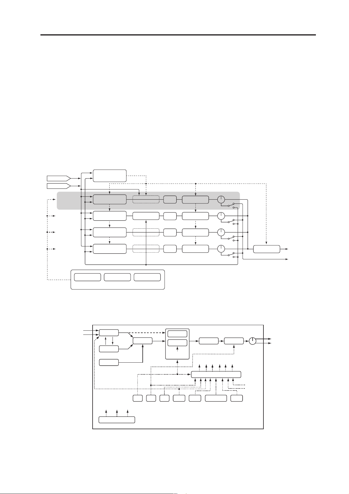
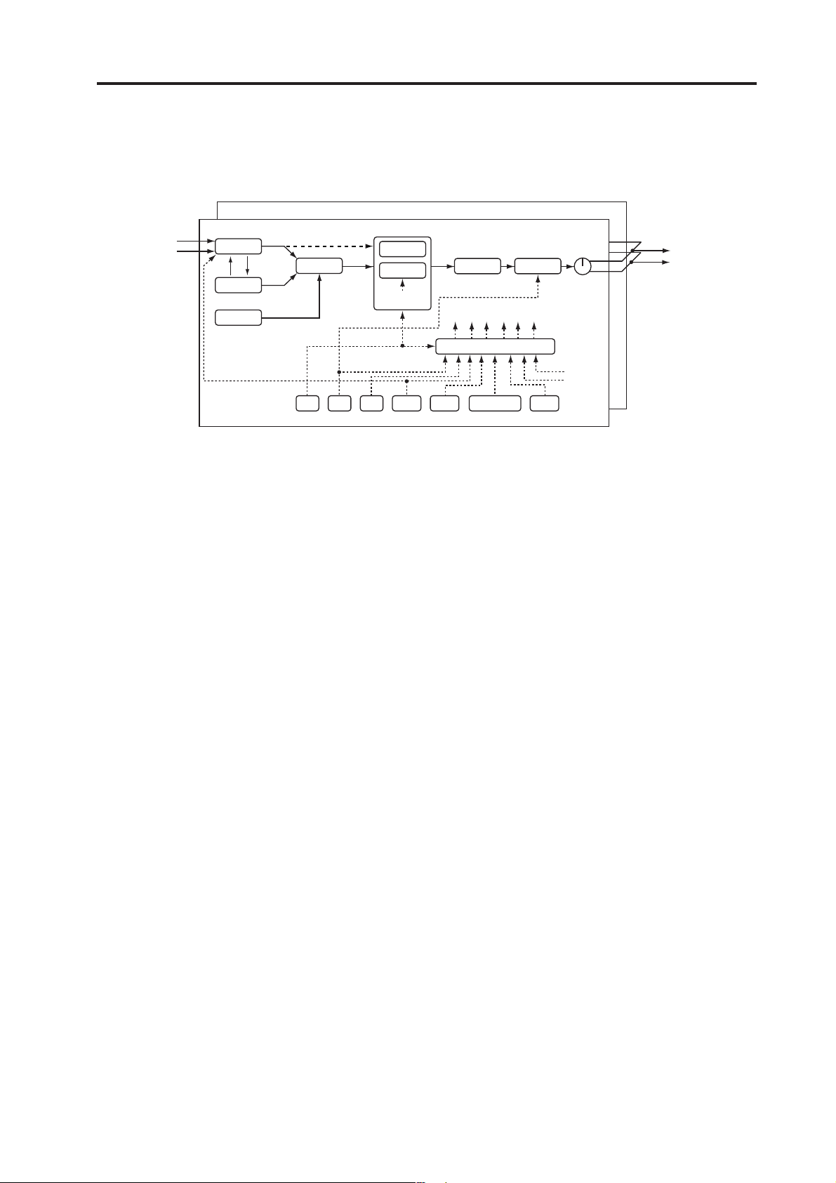
How a program is structured
Each of the RADIAS’ programs consists of four timbres, an arpeggiator, two step sequencers, a vocoder, a
master effect, and a envelope follower. A drum kit can also be assigned to one of the timbres.
Synthesizer
Program
How a program is structured
Audio In 1
Audio In 2
Timbre 1
Synth
Audio In 1, 2
IntBus
Arpeggiator
Envelope Follower
Synth
Synth
Synth
Drumkit
Drumkit Timbre = Timbre4
Step Seq 1 Step Seq 2
Arpeggiator/Step Sequencer
OSC1
OSC MOD
OSC2
NOISE
Vocoder
Vocoder = OFF
Carrier
InSrc = Timbre2
Filter Routing= Individual
MIXER
EQ I.FX1/2
FILTER1
FILTER2
EG1
I.FX1/2
I.FX1/2
I.FX1/2
Drive/WS Position
= PreAmp
EQ
EQ
EQ
KBD TRACK
IntBus (Internal Bus)
DRIVE/WS
Free Assign
OUTPUT
BALANCE
AMP
PAN
Master FX
To Timbre EQ
MAIN OUTPUT
(L/MONO, R)
INDIV. OUTPUT
(L, R)
Free Assign
SEQ1 SEQ2 SEQ3
MOD SEQUENCER
VIRTUAL PATCH
EG1 EG2 EG3 LFO1 LFO2 Env.FMIDI 1–5
KBD Track
Velocity
5
Page 12

Introduction
Timbre
A timbre consists of the oscillators (OSC1/OSC2/NOISE), mixer (MIXER), filters (FILTER), amp (AMP), envelope generators (EG), LFOs, virtual patches (VIRTUAL PATCH), modulation sequencers (MOD SEQ),
equalizer (EQ), and the insert effects (INSERT FX1/FX2). By editing the parameters of these sections you can
create an incredibly diverse range of sounds.
Oscillator (OSC1/OSC2/NOISE)
There are three Oscillator sources; Oscillator 1, Oscillator 2, and the noise generator. Oscillator 1 (OSC1) lets
you choose from nine different oscillator algorithms. These include conventional analog synthesizer waveforms, digital synthesizer PCM waveforms and drum PCM waveforms, formant, noise, and even an external
audio signal. Oscillator 2 (OSC2) lets you choose from four different oscillator waves - sine, triangle, square,
and sawtooth. The noise generator (NOISE) generates white noise. You can use this for a variety of sound
shaping situations, such as adding breath noise for a wind instrument sound, or as part of a special effect
sound.
For die-hard analog fans, the analog tune feature lets control the amount of simulated oscillator drift that
will be applied. Five different portamento curves allow detailed control over glissando passages and gliding
between notes. Modulation such as cross-modulation, unison, and VPM (Variable Phase Modulation) can be
applied to the analog synthesizer waveforms of Oscillator 1. Oscillator 2 can be used as the modulating oscillator for the sync modulation (SYNC) or ring modulation (RING) that are such classic analog synthesizertechniques. The best elements of SYNC and RING modulation can be combined using a third option: RING
SYNC.
Mixer (MIXER)
The mixer adjusts the volume levels of oscillator 1 (OSC1), oscillator 2 (OSC2), and the noise generator
(NOISE), and sends the combined signal to the filter (FILTER).
Filter (FILTER1/FILTER2)
The filter section consists of two multi-mode, resonant filters. The two filters can be routed in series or parallel, or even side by side in a “one oscillator per filter” arrangement. The filters adjust the tone of the sound
coming from the oscillators by boosting or cutting specific frequency regions. Filter settings will have a major
impact on the sound.
By default, envelope generator 1 (EG1) is set to vary the cutoff frequency of the filters over time.
Amp (AMP)
Traditionally, the amp section controls the output volume (AMP) and the panning (PAN), or the position in
the stereo field. The RADIAS provides additional features to add more tonal complexity and “edge” to the
sound - including Drive, Wave Shape control (DRIVE/WS), and Punch Level. By default, envelope generator 2 (EG2) is set to vary the volume level over time.
Envelope generators (EG1/EG2/EG3)
Envelope generators (EG) are used to apply time-varying change to the sound parameters.
Each EG consists of four parameters: attack time (ATTACK), decay time (DECAY), sustain level (SUSTAIN),
and release time (RELEASE). Keyboard dynamics and note number, as well as five time curves, allow for
exacting envelope articulation.
Each timbre contains three of these EGs. EG1 is assigned to control the filter cutoff frequency, and EG2 is
assigned to control the volume of the amp. You can also use virtual patching (VIRTUAL PATCH) to assign
these EGs as envelope sources for other parameters.
LFO section (LFO1/LFO2)
LFO (Low Frequency Oscillator) is used to apply cyclic change to the sound parameters.
Each timbre contains two LFOs, and for each LFO you can choose one of four waveforms. Shape control, key
sync and phase controls extend well beyond traditional LFO offerings.
By default, LFO1 is assigned to oscillator 1’s analog algorithms as the knob labelled “Control2”, and LFO2
is assigned to the modulation wheel. You can also make virtual patch settings (VIRTUAL PATCH) to assign
the LFOs as modulation sources for other parameters.
6
Page 13

How a program is structured
Virtual Patch (VIRTUAL PATCH)
The virtual patch section lets you freely assign modulation sources to modulate-able parameters, giving you
even more flexibility for creating sounds. You can make six virtual patch assignments in each timbre.
Modulation Sequencer (MOD SEQUENCER)
Using a modulation sequencer, you can apply up to sixteen discrete values (steps) to a modulate-able parameter over time, in a manner similar to vintage analog synthesizers. The modulation sequence can play
once, repeat, loop front to back, etc. - providing movement and complexity to the sound. The value can
change abruptly at each step, or it can smoothly transition from value to value. The value of each step can
be set using the sixteen front panel knobs, or by using the Motion Rec function to record knob movements
(changes in parameter values) in realtime. Each timbre provides three sequencers, allowing you to create extremely complex tonal changes.
Equalizer (EQ) and Insert Effects (INSERT FX1/FX2)
Each timbre is equipped with a two-band Equalizer to further control the overall tone. In addition, each timbre also possesses two insert effects. Thirty different effect types are available, and their 128 editable effect
program locations to save your favorites. Certain effects can by synced to the tempo of the internal clock that
is running the arpeggiator, step sequences, etc. - or to an external MIDI clock. Tempo Sync effects can be conveniently set as note values (Half-note, quarter-note, etc.).
Arpeggiator (ARPEGGIATOR) and Step Sequencer (STEP SEQUENCER)
Each program contains one arpeggiator and two step sequencers. Each timbre in a program can be assigned
to be played by the arpeggiator or by one of the step sequences. The arpeggiator lets you choose one of six
arpeggio types, and each of the thirty-two steps can be set as a note, tie or rest (off) to create more complex
arpeggio patterns. Each step sequencer lets you record a phrase of up to thirty-two steps; both sequencers
can be used together to create a single step sequence up to sixty-four steps. The playback of the step sequencer can also be set to transpose based on the notes being played on the keyboard (or via MIDI).
Master effect (MFX)
Each program contains one master effect.
You can use this to apply a reverb or delay effect to the overall combined sound of the program including
the processing applied by the insert effects of each timbre, adding the final touch to the complete program.
You can choose from thirty different effect types, and 128 editable effect programs.
Envelope follower
In electronic music terms, an envelope is the “shape” of a sound’s change in volume level from start to finish.
Each program contains an envelope follower, which generates a changing modulation source based on the
envelope of an external audio signal or an internally bussed sound. This detected envelope can also be used
to generate note-on/off events.
7
Page 14
Introduction
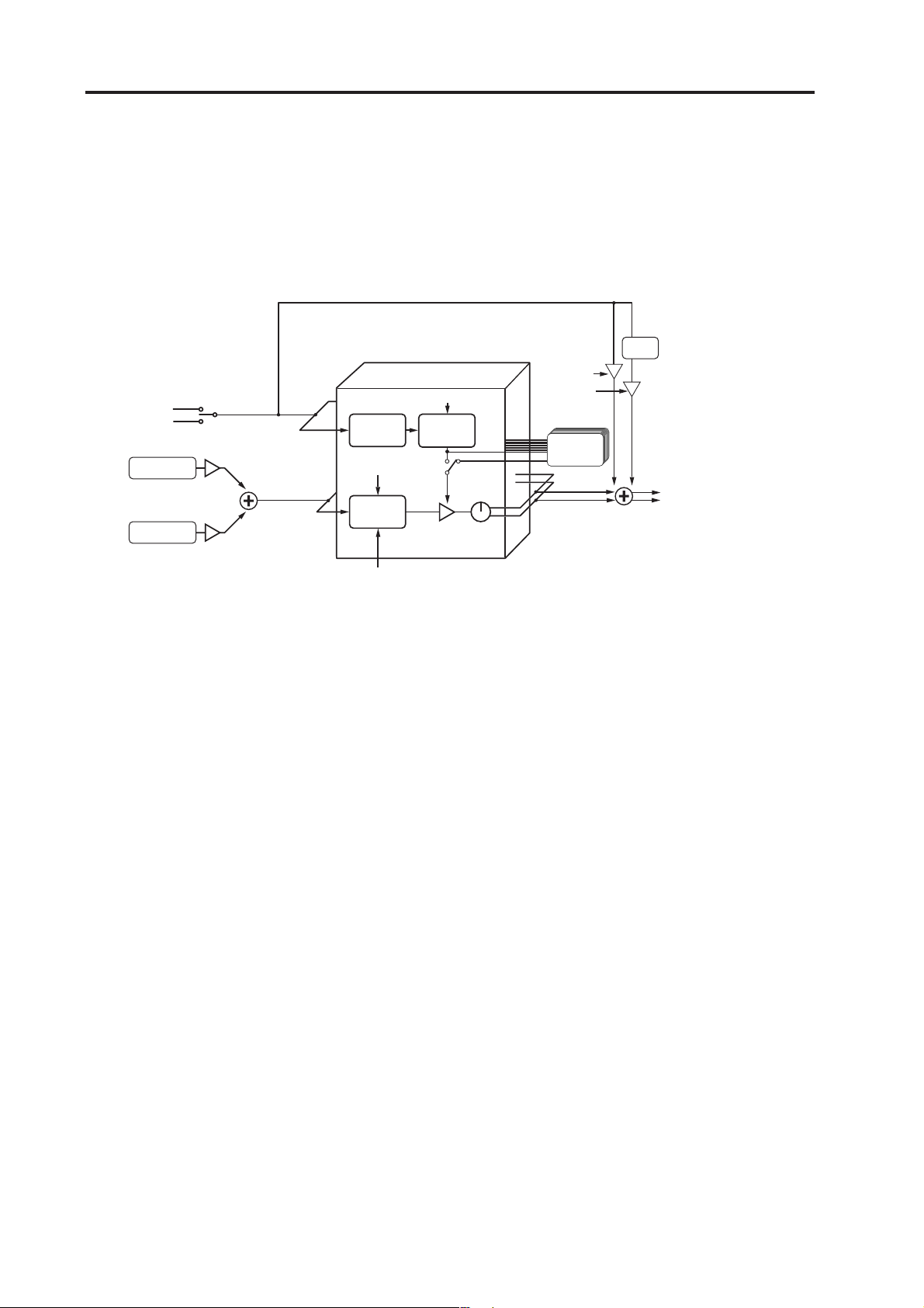
Vocoder (VOCODER)
A vocoder is available in every program The RADIAS’ vocoder contains 16 stereo bands.
A vocoder applies the spectral character of the “modulator” (e.g., a signal received from the INPUT 2 jack)
to the “carrier” (e.g., the sound of a timbre or a signal received from the INPUT 1 jack).
The most popular way to use this is to input your voice from a mic connected to the INPUT 2 jack, creating
the impression that an instrumental sound is “talking.”
Vocoder
Audio In 2
IntBus
LEVEL
Carrier InSrc1
Carrier InSrc2
LEVEL
Band16
Band1
ANALYSIS
FILTER
RESONANCE
SYNTHESIS
FILTER
E.F. SENSE
ENVELOPE
FOLLOWER
Band. LEVEL
MODULATOR
SELECT
PAN
DIRECT
LEVEL
HPF
LEVEL
FORMANT
MOTION DATA
HPF
To Carrier InSrc1 Timbre EQ
CUTOFF (FC MOD)
FORMANT SHIFT
Vocoder section (VOCODER)
The vocoder divides the audio spectrum into “bands”. In the RADIAS, the vocoder uses 16 bands. There are
actually two sets of 16 bands; the first is used to analyze the tonal characteristics of one sound (the Modulator), and the second set is used to apply the same characteristics to another sound (the Carrier). Each analysis
band contains a bandpass filter and an envelope follower. Each synthesis band contains a band pass filter
whose output is controlled by the matching envelope follower in the analysis band.
The modulator’s audio signal is sent through the sixteen bandpass filters (the analysis filters), and the envelope follower detects the volume envelope (change over time) for each of these frequency bands.
The carrier’s audio signal is sent through the other set of sixteen bandpass filters (the synthesis filters), and
the envelope detected from each analysis filter is applied to each synthesis filter to modulate the sound, producing the impression that the carrier sound is “talking” (the typical vocoder effect).
You can use the “FORMANT SHIFT” and “CUTOFF” parameters to shift the frequencies of the carrier bandpass filters. This will raise or lower the frequency response while preserving the character of the modulator,
creating major changes in the sound.
Carrier (CARRIER)
A sawtooth wave (SAW) or other waveform rich in overtones is the best choice for the carrier. As the carrier,
you can use a combination of two sources (IN SOURCE 1 and IN SOURCE 2). One of the timbres can be selected as IN SOURCE 1, and either an external input (the INPUT 1 jack) or an internally bussed sound (program output) can be selected as IN SOURCE 2.
Modulator (MODULATOR)
Most commonly, you will input your voice as the modulator, but interesting results can also be obtained by
inputting a rhythm sound as the modulator waveform. You can use either an external input (INPUT 2 jack)
or an internal bus (program output) as the modulator.
There is also a Formant Motion function that lets you record Formant Motion Data to capture the moving
characteristics of a voice or other sound, and use this data to drive the vocoder.
8
Page 15
How a program is structured
Drum kits
Drumkit
Drum Inst. 16
Drum Inst. 01
Audio In 1, 2
IntBus
OSC1
OSC2
NOISE
Each drum kit consists of sixteen drum instruments. The RADIAS contains thirty-two drum kits.
Filter Routing= Individual
OSC MOD
FILTER1
MIXER
EG1 EG2 EG3 LFO1 LFO2 Env.FMIDI 1–5
FILTER2
EG1
KBD TRACK
Drive/WS Position
= PreAmp
DRIVE/WS
Free Assign
VIRTUAL PATCH
AMP
PAN
KBD Track
Velocity
To Timbre EQ
Each drum instrument consists of OSCILLATOR, MIXER, FILTER, AMP, EQ, LFO, and VIRTUAL PATCH
settings, just as with a timbre. (☞p.6 “Timbre”)
One of the timbres in a program may be assigned a drum kit. By assigned that timbre to be played by the
arpeggiator or one of the step sequences, you can create a program that provides a rhythmic accompaniment
to your performance. (☞p.64 “Key Zone settings”)
9
Page 16
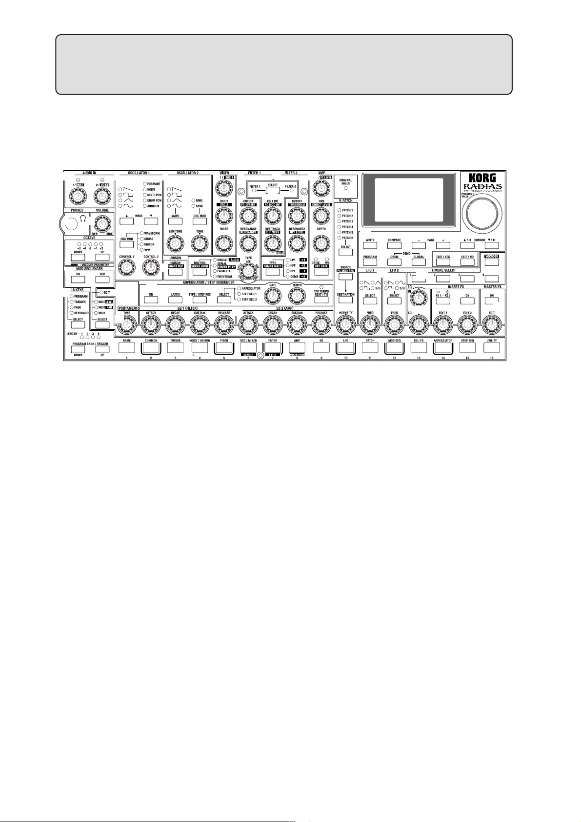
Front and rear panels
Front panel
The parameters printed in white characters on a dark background are vocoder parameters.
9
8
21
24
651
3
2
4
23
22
7
20
1. AUDIO IN
[1/INST] knob
This knob adjusts the input level from the INPUT 1 jack.
[2/VOICE] knob
This knob adjusts the input level from the INPUT 2 jack.
2. VOLUME
[VOLUME] knob
This knob adjusts the overall volume. This knob also adjusts the headphone volume.
3. PHONES
10
11
12
13
15
14
16
17
5. OSCILLATOR 1
WAVE [▲][▼] buttons
These select the waveform for oscillator 1.
The LED for the selected waveform will light.
[OSC MOD] buttons
Selects the modulation type. The LED for the selected
modulation type will light.
[CONTROL 1] knob
The parameter adjusted by this knob will depend on the
selected waveform or modulation type.
[CONTROL 2] knob
The parameter adjusted by this knob will depend on the
selected waveform or modulation type.
18
19
Headphone jack
This jack allows you to listen to the RADIAS through
stereo headphones. Connect your headphones to this
jack.
4. OCTAVE
[UP], [DOWN] buttons
These shift the pitch of the keyboard and the 16 keys [1]–
[16] in one-octave units.
☞p.22 “Changing the octave”
10
6. OSCILLATOR 2
[WAVE] button
Selects the waveform for oscillator 2.
The LED for the selected waveform will light.
[OSC MOD] button
Selects the modulation type applied by oscillator 1.
The LED for the selected modulation type will light.
[SEMITONE] knob
This knob adjusts the pitch of oscillator 2 in semitone
steps.
[TUNE] knob
This knob makes fine adjustments to the pitch of oscillator 2.
Page 17

Front panel
7. UNISON
[UNISON - FRMNT REC] button
UNISON: Switches the unison function on/off.
FRMNT REC: When editing vocoder settings, this
records format motion data for use with the Formant
Motion function.
8. MIXER
[OSC1 - SCR1] knob
OSC 1: Adjusts the volume of oscillator 1.
SCR 1: When editing vocoder settings, this adjusts the
volume of input 1 (timbre) to the carrier.
[OSC2 - SRC2] knob
OSC 2: Adjusts the volume of oscillator 2.
SCR 1: When editing vocoder settings, this adjusts the
volume of input 2 (e.g., external input) to the carrier.
[NOISE] knob
Adjusts the volume of the noise generator.
9. FILTER 1
[CUTOFF - FC OFFSET] knob
CUTOFF: Adjusts the cutoff frequency of filter 1.
FC OFFSET: When editing vocoder settings, this adjusts
the cutoff frequency offset value of the synthesis filter.
FRMNT SHIFT: When editing vocoder settings, this adjusts the amount of formant shift.
11. FILTER COMMON
[SELECT] button
Selects which filter will be affected by adjusting the EG1
INT knob and KEY TRACK knob.
The LED corresponding to the filter you select will light.
[EG1 INT - FC MOD INT] knob
EG 1 INT: Adjusts the amount of EG1 (depth) that will
be applied to the filter cutoff frequency.
FC MOD INT: When editing vocoder settings, this adjusts the depth of modulation applied to the cutoff frequency of the synthesis filter. The modulation source is
selected by the [SOURCE - FC MOD SRC] button of the
Virtual Patch section.
[KEY TRACK - E.F.SENS] knob
KEY TRACK: Adjusts the amount of keyboard tracking
that will be applied to the filter. This allow notes played
higher on the keyboard to have a different filter cutoff
than notes played lower on the keyboard.
E.F. SENS: When editing vocoder settings, this adjusts
the sensitivity of the envelope follower in the vocoder
section.
12. AMP
[RESONANCE] knob
RESONANCE: Adjusts the resonance of filter 1.
RESONANCE: When editing vocoder settings, this adjusts the resonance of the synthesis filters.
[TYPE] knob
Selects the type of filter used by filter 1.
A position between markings will produce a character
mid-way between the two filter types, allowing you to
adjust the proportion of the two types.
[ROUTING - MODULATOR] button
ROUTING: This specifies the routing (combination) of
filters 1 and 2.
MODULATOR: When editing vocoder settings, this selects the modulator.
10. FILTER 2
[CUTOFF - THRESHOLD] knob
CUTOFF: Adjusts the cutoff frequency of filter 2.
THRESHOLD: When editing vocoder settings, this adjusts the threshold level of the modulator input signal.
[RESONANCE - HPF LEVEL] knob
RESONANCE: Adjusts the resonance of filter 2.
HPF LEVEL: When editing vocoder settings, this adjusts
the output level of the HPF (High Pass Filter) applied to
the modulator input signal (e.g., the INPUT 2 jack).
[TYPE - FRMNT SHIFT] button
TYPE: Selects the type of filter used by filter 2.
[LEVEL - VC LEVEL] knob
LEVEL: Adjusts the volume of the selected timbre.
VC LEVEL: When editing vocoder settings, this adjusts
the output level of the vocoder.
[PAN - DIRECT LEVEL] knob
PAN: Adjusts the pan position of the selected timbre.
DIRECT LEVEL: When editing vocoder settings, this adjusts the direct output level of the modulator (e.g., INPUT 2 jack).
[DEPTH] knob
Adjusts the depth of the DRIVE/WS (Wave Shape) effect.
[DRIVE/WS - HPF GATE] button
DRIVE/WS: Selects which function will be applied to
the timbre. The LED for the selected function will light.
HPF GATE: When editing vocoder settings, this specifies whether the High Pass Frequency gate is enabled or
disabled (on or off).
13. V.PATCH (VIRTUAL PATCH)
[SELECT] button
Selects the patch that you will be editing. The LED of the
selected patch will light.
[SOURCE - FC MOD SRC] button
SOURCE: Selects the modulation source.
FC MOD SRC (Filter Cutoff Modulation Source): When
you’re editing vocoder settings, this selects the modula-
11
Page 18

Front and rear panels
tion source that will be applied to the cutoff frequency of
the synthesis filter.
[DESTINATION] button
Selects the modulate-able parameter that the selected
virtual patch will be applied to.
[INTENSITY] knob
Adjusts the amount of modulation that will be applied
by the currently selected virtual patch.
14. LFO1/LFO2
[SELECT] button
Selects the LFO waveform. The LED of the selected
waveform will light.
[FREQ] knob
Specifies the LFO rate. The [SELECT] button will blink
in time with the specified rate.
15. DISPLAY & BUTTON
ORIGINAL VALUE LED
When you turn a knob or press a button, this LED will
light when the setting matches the value stored in the
program.
Display
In the Program Play mode, this display shows the program names and program numbers.
In the Drum Play mode, this display shows the drum kit
numbers and drum kit names.
In other modes, this display will show the parameters
being edited.
[PROGRAM/VALUE] dial
In the Program Play mode, turning this dial selects programs. In the Drum Play mode, this selects drum kits. In
other modes turning this dial modifies the value of the
parameter selected by the cursor.
[WRITE] button
Use this button to save any edited settings. When you
press this button, you will be given the option of saving
or not saving; and you will be able to select where the
data will be saved.
[COMPARE] button
Returns the values modified by the knobs and buttons to
the values stored in the program. Use this when you
want to compare the edited sound with the sound that is
stored in the program.
PAGE [+] [–] buttons
Use these to switch pages or tab pages.
CURSOR [π/√] [†/®]
Use these to select the parameter you want to edit.
In this manual, the term “cursor” is used when referring to both the [π/√] and [†/®] buttons. If
either the [π/√] or [†/®] button is meant, we
will refer to the “cursor [π/√] button” or “cursor
[†/®] button.”
[PROGRAM] button
Press this button to enter the Program Play mode.
[DRUM] button
Press this button to enter the Drum Play mode.
[GLOBAL] button
Press this button to enter the Global mode.
[EDIT/YES] button
When you’re in one of the Play modes, press this button
to enter the corresponding Edit mode. This button is
also used to finish executing functions such as Copy or
Write.
In each Edit mode, you can specify a note number or velocity value (e.g., Program Edit mode P03–3: TIMBRE –
ZONE tab page “Bottom” or “Top”) by holding down
this button and pressing a note on the keyboard.
[EXIT/NO] button
Press this button to return from an Edit mode to the corresponding Play mode. This button is also used to cancel
a function such as Copy or Write.
You can switch each timbre on or off by holding
down this button and pressing a TIMBRE SELECT
[1]–[4] button.
16. TIMBRE SELECT
[1], [2], [3], [4] buttons
In the Program Play mode, these buttons select the timbre that can be edited from the front panel. By holding
down the [EXIT/NO] button while pressing one of the
timbre select buttons, you can turn the individual timbre
off and on again.
In the Program Edit mode, these buttons select the timbre to be edited.
You can’t select a timbre that is turned off (i.e.,
whose button is dark). If you want to turn the timbre on, you can either make settings in Program
Edit mode, or hold down the [EXIT/NO] button
and press a [1]–[4] button to switch the corresponding timbre on or off.
[VOCODER] button
Switches the vocoder on/off. In the Edit mode, press
this when you want to edit the vocoder settings.
17. EQ (EQUALIZER)
[HI] knob
Adjusts the level of the high frequency range. Turning
this toward the right will boost the level of the high frequency range, and turning it toward the left will decrease the level of the high frequency range.
You can specify the center frequency of the high frequency range in the Program Edit mode P13–1: EQ/FX –
EQ tab page.
12
Page 19

Front panel
[LO] knob
Adjusts the level of the low frequency range. Turning
this toward the right will boost the level of the low frequency range, and turning it toward the left will decrease the level of the low frequency range.
You can specify the center frequency of the low frequency range in the Program Edit mode P13–1: EQ/FX – EQ
tab page.
18. INSERT FX
[FX1-FX2] button
Selects which insert effect is available for editing. FX1
parameters is selected when this button is dark, and FX2
is selected when this button is lit.
[ON] button
Turns the insert effect selected by [FX1-FX2] on/off.
When this button is lit, the effect is on and will be applied.
[EDIT1], [EDIT2] knobs
These knobs adjust various effect parameters.
They will adjust the effect selected by the [FX1-FX2] button. The parameter being adjusted will depend on the
type of effect selected.
button to enter record-ready mode; recording will begin
when you play the keyboard etc.
[SELECT] button
Selects the arpeggiator or the step sequencer that will be
assigned to play the timbre.
[GATE] knob
Adjusts the gate time (duration) specified for each step
of the arpeggiator or step sequencer.
[TEMPO] knob
Adjusts the playback tempo of the arpeggiator or step
sequencer. This setting will also affect other parameters
that are tied to the internal tempo, such as playback
speed of a modulation sequencer, an LFO rate, or an effect delay rate.
[TAP TEMPO REST/TIE] button
During playback, you can enter a tempo manually by
lightly tapping this button a few times at the desired
tempo (Tap Tempo). When you’re recording using the
step sequencer, this button allows you to enter ties and
rests.
TEMPO LED
This will blink at quarter note intervals of the current
tempo.
19. MASTER FX
[ON] button
Switches the master effect on/off. When this button is
lit, the effect is on.
[EDIT] knob
Adjusts various master effect parameters. The parameter being adjusted will depend on the effect type you’re
using.
20. ARPEGGIATOR/STEP SEQUENCER
[ON] button
This turns the arpeggiator and step sequencers on/off.
The arpeggiator and step sequencers are all turned on
together
[LATCH] button
This button turns on and off the Latch function that affects the arpeggiator and the step sequencers.
When this function is on (lit), the arpeggiator and/or
step sequencers will continue playing even after you
take your hand off the keyboard.
The latch setting can be set independently for the arpeggiator and each step sequencer.
[TYPE/STEP REC] button
The function of this button depends on the setting of the
[SELECT] button, which can be set to ARPEGGIATOR,
STEP SEQ 1, or STEP SEQ 2. If ARPEGGIATOR is selected, pressing this button will scroll through the different
arpeggiator types.
If STEP SEQ 1 or 2 is selected, then this button will act as
the recording button for that step sequencer. Press this
21. EG1 (FILTER)/EG2 (AMP)
[ATTACK] knob
Adjusts the attack time (rise time from the key on).
[DECAY] knob
Adjusts the decay time (the time from the end of the attack time until the sustain level is reached).
[SUSTAIN] knob
Adjusts the sustain level (the level at which the sound is
held).
[RELEASE] knob
Adjusts the release time (the time it takes the sound to
completely stop after you release the key).
22. PORTAMENTO
[TIME] knob
Adjusts the way in which portamento is applied.
23. MOD SEQUENCER
[ON] button
Switches the modulation sequencer on/off.
When the button will be lit, the modulation sequencer
will be on, and will be active during playback.
[REC] button
Records your knob movements in realtime into the
modulation sequencer.
13
Page 20
Front and rear panels
[SELECT] button
In addition to selecting the function of the 16 knobs
above the 16 panel keys, this button also selects which
Mod Sequencer is available for editing.
If EDIT is selected, the sixteen knobs can be used to edit
the program parameters labelled above each knob. (portamento, EG1, EG2, etc.).
If MOD1, MOD2, or MOD3 is selected, the sixteen knobs
will edit the data at the corresponding step of the modulation sequencer.
When you’re editing vocoder settings, the sixteen knobs
adjust the level or pan of each synthesis filter (output
band).
24. 16 KEYS
[SELECT] button
This button selects the function of the 16 panel keys [1]–
[16]. The functions that can be selected will depend on
the mode. The LED of the selected function will light.
If you select PROGRAM, the sixteen keys can be used to
select the programs in the current bank. In the Drum
Play mode, the sixteen keys can be used to play drum instruments from the front panel.
If you select TRIGGER, the sixteen keys will toggle individual arpeggiator notes on/off, or indicate the steps of
the step sequencer.
If you select PAGE, the sixteen keys will select editing
pages or global mode pages.
If you select KEYBOARD, keys [1]–[16] will function as
a simple polyphonic MIDI keyboard, and will play the
sound of the current program.
The simple MIDI keyboard function of keys [1]–
[16] is available only if the dedicated keyboard is
not connected.
PROGRAM BANK/TRIGGER [UP], [DOWN] buttons
The function of these buttons will depend on the state of
the [SELECT] button.
If the [SELECT] button is set to PROGRAM, these buttons will select the program bank or drum kit (Drum
Play mode).
If the [SELECT] button is set to TRIGGER, these buttons
will select which step of the arpeggiator or step sequencer will be edited.
If the [SELECT] button is set to PAGE or KEYBOARD,
these buttons have no function.
LENGTH LED 1...4
These indicate the length of the arpeggiator or step sequencer that is currently being played or edited. One
length indicates sixteen steps.
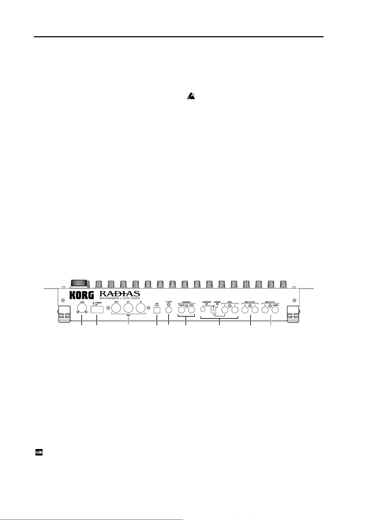
Rear panel
9
8
7
1. MAIN OUTPUT
L/MONO, R jacks
These are the main stereo audio output jacks.
Use these jacks to connect the RADIAS to your powered
monitor speakers, stereo amp, mixer, or multitrack recorder, etc. If you’re using a monaural connection, use
the L/MONO jack.
2. INDIV. OUTPUT
L, R jacks
These are sub stereo audio output jacks.
The output destination of each timbre can be set to
either MAIN OUTPUT or INDIV. OUTPUT. The
output destination of each timbre is specified in
the Program Edit mode P03–2: TIMBRE – OUT tab
page. (☞p.78 “P03–2: OUT (Timbre Output)”)
6
5
4
3
2
1
3. INPUT
INPUT 1 jack
You can connect a synthesizer or audio device to this
jack. The input signal can be used as the waveform for
oscillator 1.
When using the RADIAS as a vocoder, this jack will be
the input for the external carrier.
INPUT 2 jack
You can also connect a synthesizer or audio device to
this jack. In conjunction with the INPUT 1 jack, the input
signal can be used as the waveform for oscillator 1.
When using the RADIAS as a vocoder, this jack will be
the input for the external modulator.
[SOURCE SELECT] switch
Set this appropriately for the source that’s connected to
the INPUT 2 jack.
14
Page 21

Use the DYNAMIC MIC setting if you’re connecting a
mic to the INPUT 2 jack.
Use the LINE setting if you’re connecting a line-level device such as a synthesizer or audio device to the INPUT
2 jack.
Use the CONDENSER MIC setting if you’re connecting
the headset mic that came with the RADIAS to the
CONDENSER MIC jack.
CONDENSER MIC jack
Connect the mic that came with the RADIAS to this
jack.
Do not connect anything other than the included
mic to the CONDENSER MIC jack.
4. ASSIGNABLE
PEDAL jack
Connect a foot pedal (expression pedal) to this jack.
SWITCH jack
Connect a foot switch to this jack.
Rear panel
5. TO KYBD (TO KEYBOARD) connector
Connect the RADIAS’ dedicated keyboard to this connector.
6. USB connector
Use a USB cable to connect the RADIAS to your computer via this jack. This connection is used to transmit/
receive MIDI data, and to exchange data with the included RADIAS Sound Editor software.
7. MIDI
MIDI IN connector
This connector receives MIDI messages. Connect it to
the MIDI OUT connector or MIDI THRU connector of an
external MIDI device.
MIDI OUT connector
This connector transmits MIDI messages. Connect it to
the MIDI IN connector of an external MIDI device.
MIDI THRU connector
Received MIDI messages are passed on without change
from this connector. Use this when you want to send the
same stream of MIDI messages to more than one device.
8. ON/STANDBY
[ON/STANDBY] switch
Turns the power on/off.
9. AC9V
AC9V connector
Connect the included AC/AC power supply here.
15
Page 22
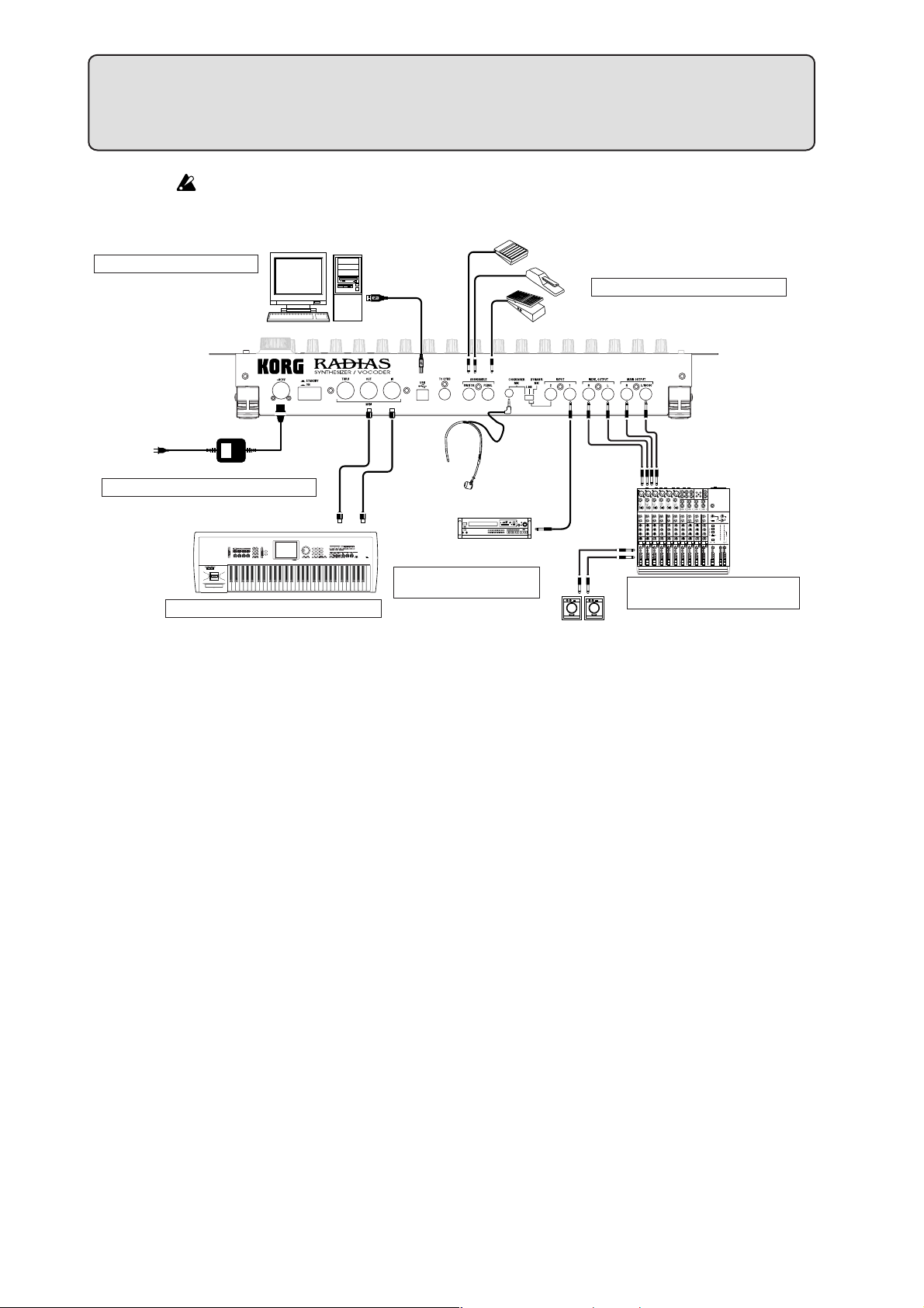
Make all your connections with the power off (on all units!). If you don’t, you may damage your
speaker system or damage your RADIAS and/or other equipment. Please use caution.
6. Connecting your computer
to AC outlet
Computer
Setup
USB cable
ASSIGNABLE SWITCH
DAMPER
3. Connecting pedals and switches
PEDAL
AC/AC power supply
1. Connecting the AC/AC power supply
4. Connecting external MIDI equipment
MIDI IN
MIDI cable
MIDI OUT
5. Connecting the audio
inputs – INPUT jacks
Mic
CD player, analog
record player, etc.
AUDIO OUTPUT/
AUX OUT etc.
MIC1
BAL
BAL
OR
OR
UNBAL
UNBAL
LINE IN 3
LINE IN 2
LINE IN 1
LOW CUT
LOW CUT
75Hz
75Hz
18dB/OCT
18dB/OCT
B
B
V
V
d
d
0
0
1
1
-
-
G
G
A
A
I
I
C
C
N
N
I
I
M
M
U
U
U
10
10
60
60
+10dB
+10dB
-40dB
-40dB
TRIM
TRIM
U
U
AUX
AUX
1
1
MON/
MON/
EFX
EFX
+15
+15
U
U
2
2
EFX
EFX
+15
+15
U
U
EQ
EQ
HI
HI
12kHz
12kHz
-15
-15
-15
+15
+15
U
U
MID
MID
2.5kHz
2.5kHz
-12
-12
-12
+12
+12
U
U
Monitor
LOW
LOW
80Hz
80Hz
+15
+15
-15
-15
-15
PAN
PAN
L
R
R
OUTPUT
1
2
MUTE
MUTE
MUTE
ALT 3–4
ALT 3–4
ALT 3–4
dB
dB
dB
10
10
10
SOLO
SOLO
5
5
5
U
U
U
5
5
5
10
10
10
20
20
20
30
30
30
40
40
40
50
50
50
60
60
60
INPUT
2. Connecting external audio
OUTPUT
INPUT
1
1
L
2
2
R
ALL BAL/UNBAL
LEFT(1/MONO)
RIGHT
BAL
BAL
BAL
BAL
MONO
MONO
MONO
OR
OR
OR
OR
UNBAL
UNBAL
UNBAL
UNBAL
L
L
L
LINE IN 4
LINE IN 6
LINE IN 5
BAL
BAL
BAL
LOW CUT
OR
LOW CUT
OR
OR
LOW CUT
LOW CUT
75Hz
75Hz
75Hz
75Hz
UNBAL
UNBAL
UNBAL
18dB/OCT
18dB/OCT
18dB/OCT
18dB/OCT
B
B
B
B
V
V
V
V
d
d
d
d
0
0
0
0
1
1
1
1
-
-
-
-
R
R
R
G
G
G
G
A
A
A
A
I
I
I
I
C
C
C
C
N
N
N
N
I
I
I
I
M
M
M
M
U
U
U
LEVEL
LEVEL
LEVEL
+4
+4
+4
10
10
10
10
60
60
60
60
-10
-10
-10
+10dB
+10dB
+10dB
+10dB
-40dB
-40dB
-40dB
-40dB
LINE IN 7-8
LINE IN 13-14
LINE IN 9-10
LINE IN 11-12
TRIM
TRIM
TRIM
TRIM
U
U
U
U
U
U
U
AUX
AUX
AUX
AUX
AUX
AUX
AUX
1
1
1
1
1
1
1
MON/
MON/
MON/
MON/
MON/
MON/
MON/
EFX
EFX
EFX
EFX
EFX
EFX
EFX
+15
+15
+15
+15
+15
+15
+15
U
U
U
U
U
U
U
2
2
2
2
2
2
2
EFX
EFX
EFX
EFX
EFX
EFX
EFX
+15
+15
+15
+15
+15
+15
+15
+15
U
U
U
U
U
U
U
EQ
EQ
EQ
EQ
EQ
EQ
EQ
HI
HI
HI
HI
HI
HI
HI
12kHz
12kHz
12kHz
12kHz
12kHz
12kHz
12kHz
-15
-15
-15
-15
-15
-15
+15
+15
+15
+15
+15
+15
+15
U
U
U
U
U
U
U
MID
MID
MID
MID
MID
MID
MID
2.5kHz
2.5kHz
2.5kHz
2.5kHz
2.5kHz
2.5kHz
2.5kHz
-12
-12
-12
-12
-12
-12
+12
+12
+12
+12
+12
+12
+12
U
U
U
U
U
U
U
LOW
LOW
LOW
LOW
LOW
LOW
LOW
80Hz
80Hz
80Hz
80Hz
80Hz
80Hz
80Hz
+15
+15
+15
+15
+15
+15
+15
-15
-15
-15
-15
-15
-15
PAN
PAN
PAN
PAN
PAN
PAN
PAN
R
R
R
R
R
R
R
9–10
13–14
6
11–12
7–8
4
5
3
MUTE
MUTE
MUTE
MUTE
MUTE
MUTE
MUTE
ALT 3–4
ALT 3–4
ALT 3–4
ALT 3–4
ALT 3–4
ALT 3–4
ALT 3–4
dB
dB
dB
dB
dB
dB
dB
10
10
10
10
10
10
10
SOLO
SOLO
SOLO
SOLO
SOLO
SOLO
SOLO
5
5
5
5
5
5
5
U
U
U
U
U
U
U
5
5
5
5
5
5
5
10
10
10
10
10
10
10
20
20
20
20
20
20
20
30
30
30
30
30
30
30
40
40
40
40
40
40
40
50
50
50
50
50
50
50
60
60
60
60
60
60
60
TAPE
TAPE
STEREO AUX RETURNS
AUX SEND
MIC4
MIC6
MIC3
MIC5
MIC2
equipment
MAIN OUTS
L
R
BAL/UNBAL
MONO
L
BAL
OR
UNBAL
R
LEVEL
+4
-10
U
AUX
1
MON/
EFX
+15
U
PRE
2
POST
EFX
+15
U
EQ
HI
12kHz
-15
+15
U
MID
2.5kHz
-12
+12
U
LOW
80Hz
+15
-15
PAN
R
PHANTOM
CONTROL
ROOM
SOLO
Powered monitors, etc.
1. Connecting the AC/AC power supply
Connect the included AC/AC power supply to the RADIAS.
After you’ve connected the AC/AC power supply to the RADIAS, plug it into an AC outlet.
2. Connecting external audio equipment
Connect the OUTPUT jacks of the RADIAS (MAIN OUTPUT, INDIV. OUTPUT) to your audio equipment
(e.g., mixer or powered monitors). If you’re using a monaural connection, connect the L/MONO jack.
To take full advantage of the RADIAS’ superb sound, we recommend that you output in stereo.
3. Connecting pedals and switches
Jacks are provided so that you can connect both a foot switch and a foot pedal (both sold separately) to the
RADIAS for additional control.
PHONES
U
U
1
+20
+10
NORMALLED
U
AUX 1 MASTER
2
AUX
EFX TO
AUX 1
+20
MONITOR
SELECT
RETURNS
SOURCE
LEFT RIGHT
MAIN
CLIP+28
MIX
+10
+7
ALT
+4
3-4
+2
0
TAPE
-2
-4
-7
ASSIGN
-10
TO MAIN MIX
-20
NORMAL(AFL)
-30
LEVEL SET(PFL)
SOLO
0dB=0dBu
MODE
POWER
RUDE SOLO LIGHT
/ PHONES
MAIN MIX
dB
dB
10
10
5
5
U
U
5
5
10
10
20
20
30
30
40
40
50
50
60
60
16
ASSIGNABLE PEDAL jack
By connecting a pedal such as the Korg EXP-2 or XVP-10 to this jack. you can send control messages such as
breath control, volume, pan, expression, etc. while keeping your hands free for performing.
The function controlled by the pedal can be specified in the Global mode P08: PEDAL & SW page “A.Pedal.”
The factory default setting for the assignable pedal is Expression (Exp Pedal).
☞p.119 “A.Pedal (Assignable Pedal)”
ASSIGNABLE SWITCH jack
This jack is used for a switch type of pedal such as the Korg PS-1 pedal switch or Korg DS-1H damper pedal.
The foot switch can be used for various functions including switching programs, changing octaves, or turning portamento or the arpeggiator on/off. The pedal can be set to act as a momentary pedal, or as a toggle
type of switch pedal. The function controlled by the switch can be specified in the Global mode P08: PEDAL
& SW page “A.SwFunc.” The factory default setting for the assignable switch is Damper.
Page 23
Specify the pedal polarity in the Global mode P08: PEDAL & SW page.
☞p.119 “P08–1: PEDAL/SW”
☞p.119 “A.SwFunc (Assignable Switch Function)”
4. Connecting external MIDI equipment
The RADIAS can be used as a multitimbral MIDI sound module, or as a controller for other MIDI equipment.
Using the RADIAS as a sound module
If you are using the RADIAS as a sound module, use a MIDI cable to connect the RADIAS’ MIDI IN connector to the MIDI OUT connector of your external MIDI device.
Using the RADIAS as a master keyboard
If you want to play an external MIDI device from the RADIAS’ keyboard, use a MIDI cable to connect the
RADIAS’ MIDI OUT connector to the MIDI IN connector of your external MIDI device.
MIDI channel settings – Getting ready to play
If you’re using the RADIAS as a sound module or as a master keyboard, you’ll need to set the RADIAS’
global MIDI channel to match the MIDI channel of the external MIDI device that you’ve connected.
To set the RADIAS’ global MIDI channel, use the Global mode P04: MIDI page “MIDI Ch” setting.
Setup
Here’s the procedure for setting the MIDI channel.
1 Make sure that the RADIAS is correctly connected to your external MIDI device.
2 Press the [GLOBAL] button.
You will enter the Global mode. The display will show the Global mode P01: GLOBAL page.
3 Use the 16KEYS [SELECT] button to select PAGE (the
PAGE LED will light), and then press the 16KEYS [4]
button.
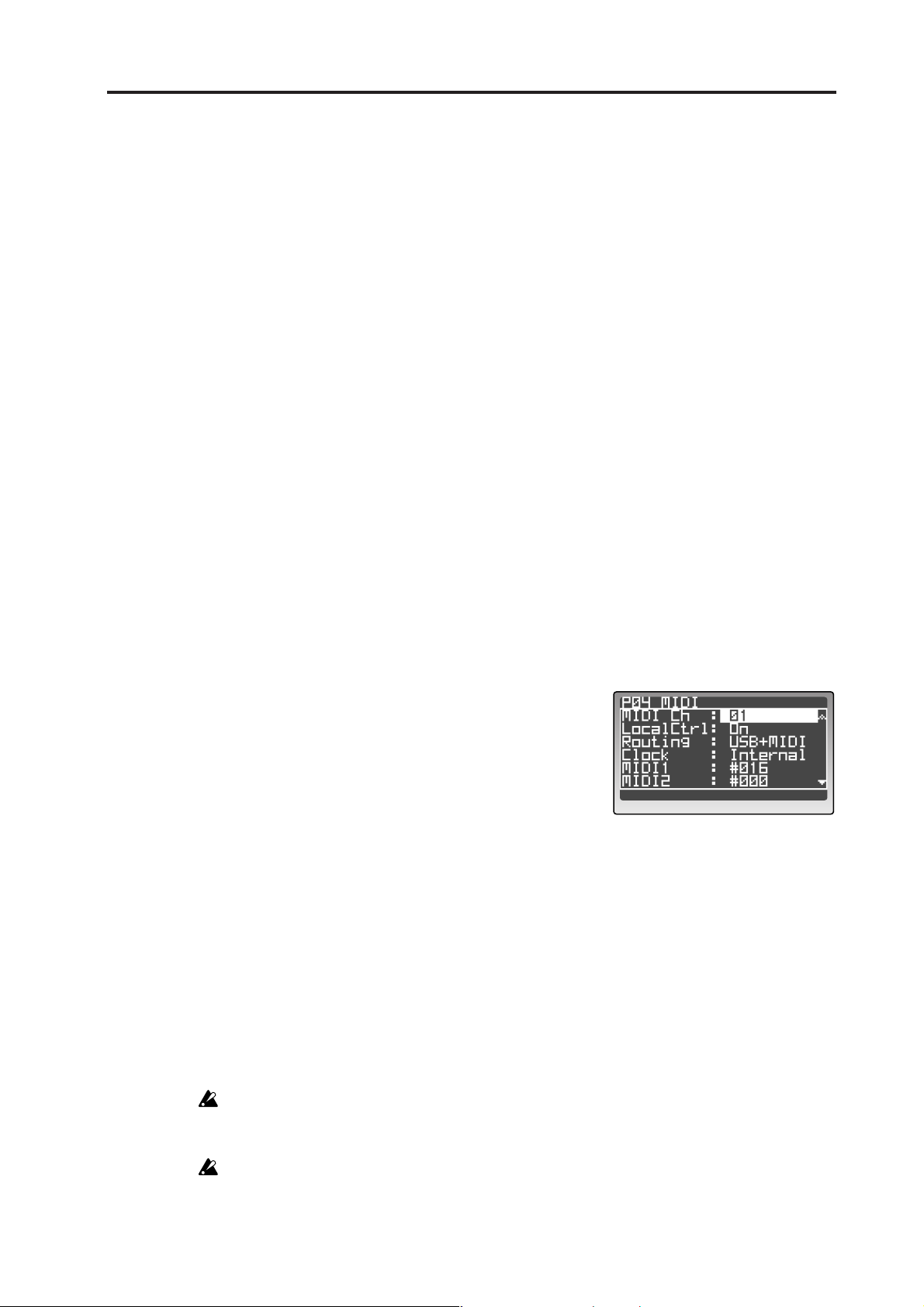
The display will show the P04: MIDI page.
4 Use the cursor buttons to select “MIDI Ch,” and use
the [PROGRAM/VALUE] dial to specify the MIDI
channel.
With the factory settings, the global MIDI channel is set
to 1. Set this to match the MIDI channel of the external
MIDI device you’ve connected.
5 Make sure that the “Routing” setting is set to USB+MIDI or MIDI.
“Routing” specifies whether MIDI data will be transmitted/received via the USB connector or the
MIDI connectors. If this is set to USB, use the cursor buttons to select “Routing” and then use the
[PROGRAM/VALUE] dial to choose USB+MIDI or MIDI.
With this setting, MIDI data will be transmitted/received via the MIDI connectors.
6 Press the [PROGRAM] button to return to the Program Play mode.
7 Set the MIDI channel of the connected external MIDI device to match the RADIAS’ MIDI
channel setting.
For details on how to do this, refer to the owner’s manual of the external device.
Any Global parameters that you edit will revert to their prior state if you turn off the power without
writing the changes into memory. If you want to keep your changes, be sure to perform the Write
operation. For details on Write, refer to p.68 “5. Saving global parameters (Write).”
A RADIAS program consists of up to four timbres, and you can specify the MIDI channel individually for each timbre. If you’re playing the RADIAS from an external MIDI device, only the timbre(s) set to the same channel as the global channel will produce sound.
17
Page 24
Setup
5. Connecting the audio inputs – INPUT jacks
You can connect any audio source (synthesizer, CD player, etc.) to the INPUT jacks. Via this connection, the
audio coming from this external source can be processed in the same way as the RADIAS’ internal sound
generator, or used as the carrier or modulator for the vocoder. You can also use the RADIAS as an effect
processor for an external audio source.
For details on these settings, refer to p.26 “Processing an external audio source.”
6. Connecting your computer
The RADIAS provides both MIDI connectors and a USB connector.
Both can transmit and receive MIDI data in the same way. Use the type of connection that’s appropriate for
your setup. You’ll need to set the Global mode P04: MIDI page “Routing” appropriately for the connection
you use. (☞p.116 “Routing”)
Data transfer is faster via the USB connection, so we recommend that you use the USB connector.
If you use MIDI cables to connect the RADIAS to your computer, you’ll need to purchase a separate MIDI interface of the appropriate type for your computer. For details on connecting the MIDI
interface to your computer and how to set the MIDI ports, refer to the owner’s manual for your
MIDI interface.
If you use an external MIDI sequencer or a sequencer program on the computer you’ve connected,
playing the RADIAS’ keyboard will cause notes to be sounded in duplicate if your sequencer’s
Echo Back setting is turned on. Go to the RADIAS’ Global mode P04: MIDI page and turn “Local
Ctrl” off (☞p.116 “Local Control”) so that the internal connection is disconnected. However, be
aware that if Local Control is off, there will be no sound if you play the RADIAS’ keyboard when
using the RADIAS by itself.
Connections via the MIDI connectors
Use MIDI cables and a MIDI interface to connect the RADIAS to your computer.
Connections via the USB connector
Use a USB cable to connect the RADIAS to your computer.
For details on the appropriate settings to make on the RADIAS so that you can use the RADIAS Sound Editor software, refer to p.71 “Using the included RADIAS Sound Editor software.” For details on installing the
software, connecting and adjust the RADIAS’ settings, and using the software, refer to “USB-MIDI driver
installation and settings” and the RADIAS Sound Editor software owner’s manual on the CD-ROM included
with your RADIAS.
Connecting the RADIAS’ dedicated keyboard RD-KB
For details on how to connect the keyboard, refer to the owner’s manual included with the keyboard RD-KB.
18
Page 25
Quick Start
The RADIAS contains demo songs, numerous programs, and a wide range of advanced features and functions. For a quick introduction to all this fun, follow along with this Quick Start guide.
Turning on the power and adjusting the volume
By now, you’ve used the preceding pages to hook up your RADIAS correctly, and you’re ready to begin
exploring.
Turning the power on/off
Be sure all the other equipment connected to the RADIAS is off before turning the RADIAS on.
1 Press the rear panel [ON/STANDBY] switch to turn
on the power.
The start -up screen will appear in the display, and then
the display will show the Program Play mode screen.
Each time you turn the power on, the RADIAS will be
in the Program Play mode.
2 Turn on the other equipment that’s connected to the
RADIAS.
When you’re ready to turn the power off, first turn off
the power of the connected equipment, and then press
the [ON/STANDBY] switch on the RADIAS’ rear panel to turn off the power.
Adjusting the volume
Begin with the [VOLUME] knob all the way down. Play a
few notes on the keyboard and gradually raise the volume to
an appropriate level using the [VOLUME] knob. This knob
also adjusts the headphone volume.
Demo playback
The RADIAS contains demo songs that take advantage of its rich sounds and expressive potential.
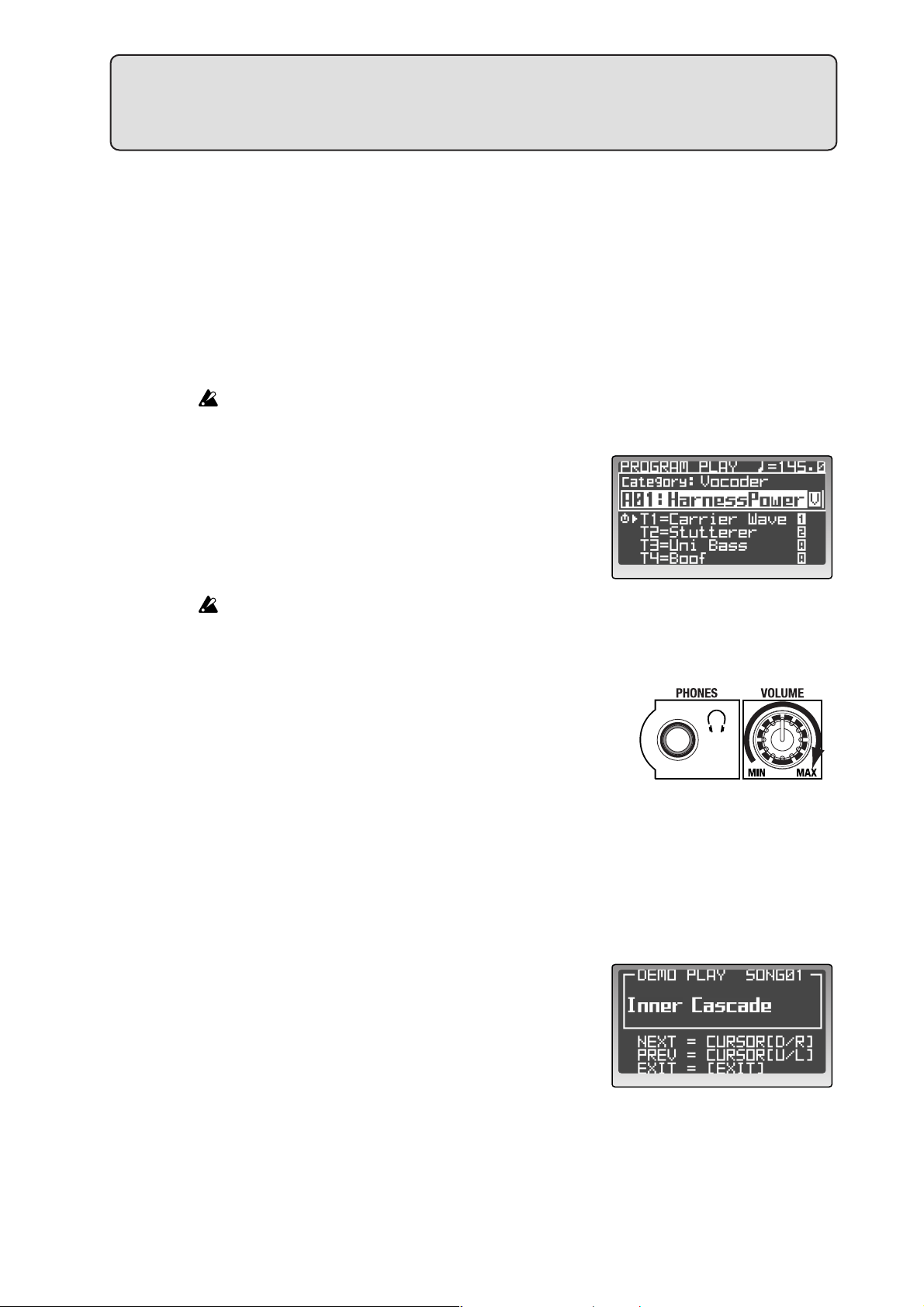
Playing the demo songs
1 While holding down the [DRUM] button, press the
[GLOBAL] button for approximately one second.
The demo songs will play consecutively, starting with
the first song.
During playback, the display will show the song name.
2 You can press the cursor buttons to switch demo
songs during playback.
3 Press the [EXIT] button to stop demo playback and
return to the Program Play mode.
All Demo Songs: © 2005 KORG Inc. — all rights reserved.
19
Page 26
Quick Start
Playing programs – Program Play mode
The RADIAS contains a total of 256 programs, organized into sixteen banks (A–P) with sixteen programs in
each bank. Here’s how to select and play different programs.
Entering the Program Play mode
The RADIAS defaults to the Program Play mode each time the power is turned on.
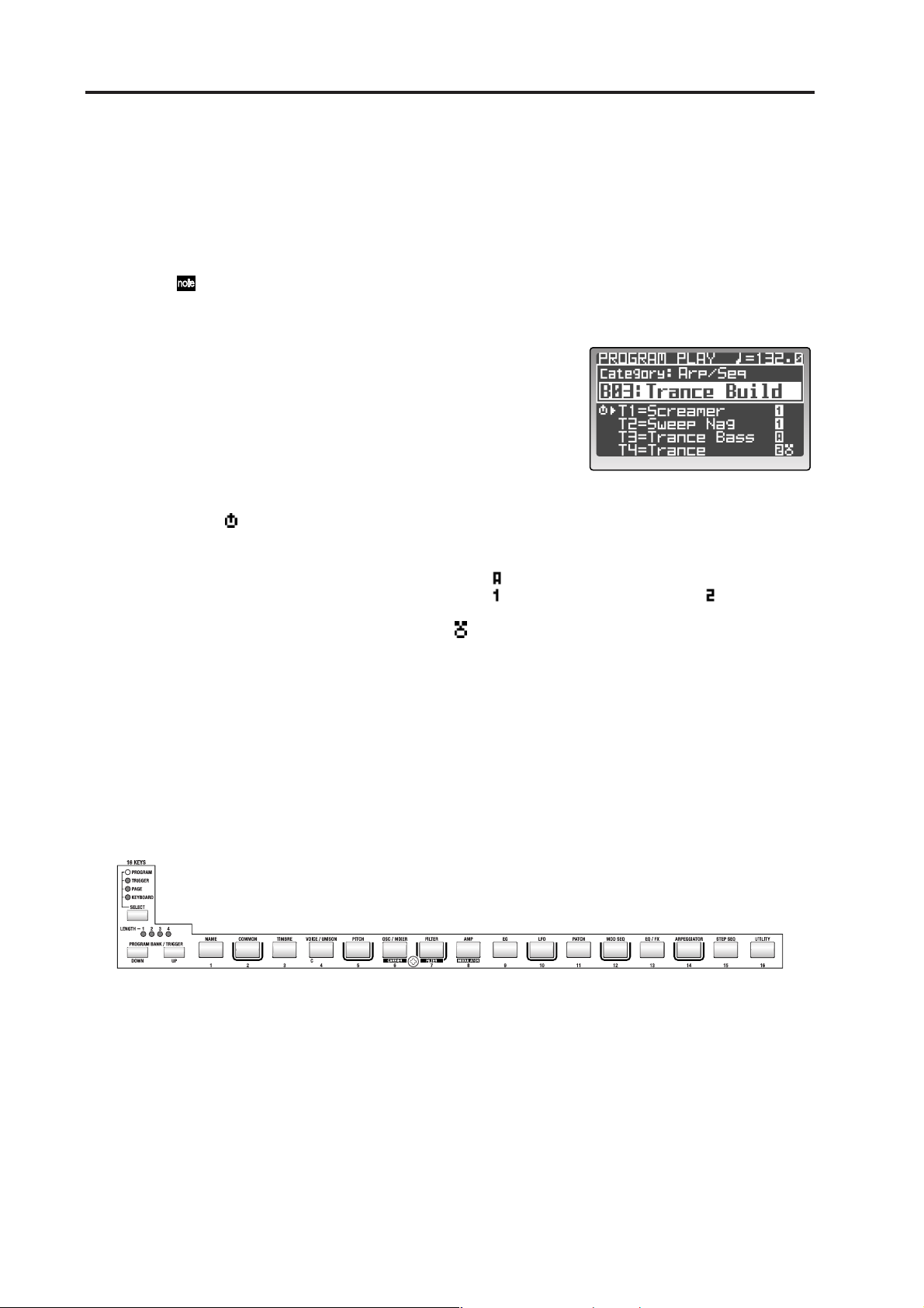
1 Press the [PROGRAM] button.
When the RADIAS is in the Program Play mode, the
[PROGRAM] button will be lit, and the top line of the
display will read PROGRAM PLAY.
The rest of the display will show various information
such as the tempo, program category, bank, number,
program name, and the names of the timbres used by
the program.
Below the program name is a list of the timbre names
that are active (turned on) in the current program. Timbres that are off are shown as “------------”.
A symbol at the left of a timbre name indicates the timbre that can be edited by the front panel
knobs and buttons. To specify the timbre that you want to edit from the front panel, use the Program Edit mode P02–1: COMMON – PROG tab page “PanelEdit” setting (☞p.75 “PanelEdit”).
If the arpeggiator is assigned to a timbre, an “ ” symbol is shown at the right of the timbre name.
If a step sequencer is assigned to a timbre, a “ ” symbol (step sequencer 1) or “ ” symbol (step
sequencer 2) is shown at the right of the timbre name.
If a drum kit is assigned to a timbre, a “ ” symbol is shown at the right of the timbre name.
In the illustration at the above right, step sequencer 1 is assigned to timbre 1 and timbre 2, the
arpeggiator is assigned to timbre 3, and a drum kit and step sequencer 2 are assigned to timbre 4.
Selecting and playing a program
You can select a program in a variety of ways.
Go ahead and get familiar with selecting and listening to the wide variety of programs provided by the RA-
DIAS.
Using the 16KEYS PROGRAM BANK/TRIGGER [UP]/[DOWN] buttons and [1]–[16] keys
This method lets you quickly select a specific program.
1 Use the 16KEYS [SELECT] button to choose PROGRAM (the PROGRAM LED will light).
2 Use the PROGRAM BANK/TRIGGER [UP] or [DOWN] button to select a bank.
There are 16 banks, A–P. Use these buttons to choose a bank.
3 Use the 16KEYS [1]–[16] to select a program number.
Program numbers 1–16 in each bank correspond to 16KEYS [1]–[16]. This way, you can directly
select the desired program from within the bank.
20
Page 27
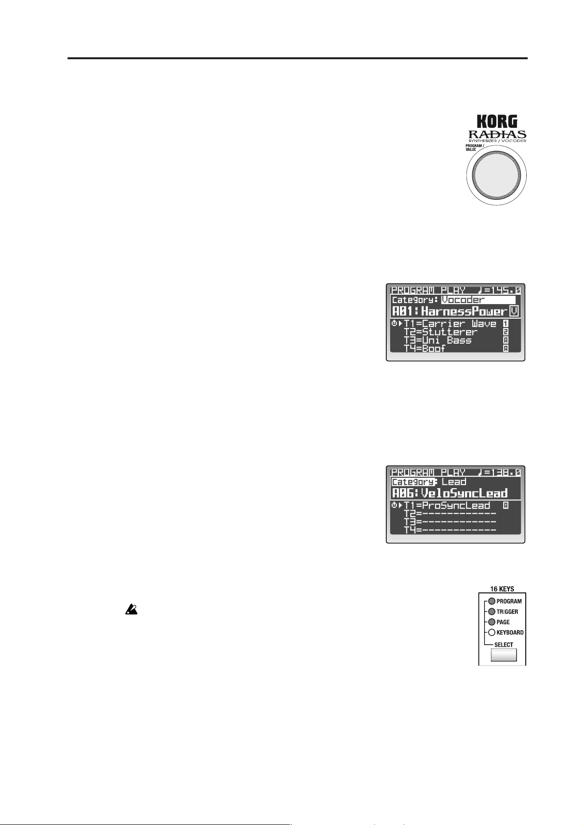
Playing programs – Program Play mode
Using the [PROGRAM/VALUE] dial
You can use the [PROGRAM/VALUE] dial to select programs.
Turn the dial toward the right to step through the programs in ascending
order, or toward the left in descending order.
Selecting programs by category
Each program can be assigned to a category. You can select programs by from within a category. This is convenient when you want to find a program with the same type of sound.
1 Use the cursor [π/√] button to move the cursor to the
category indication in the display.
2 Use the [PROGRAM/VALUE] dial to select the
desired category.
The factory-set categories are listed below.
1: Bass 9: Bell/Decay
2: Lead 10: Acoustic
3: Synth Hard 11: S.E/Hit/Drum
4: Synth Soft 12: Arp/Seq
5: Motion 13: Split
6: Strings/Pad 14: Audio In
7: Keyboard 15: Vocoder
8: Guitar/Pluck 16: User
3 Use the cursor [π/√] button to move the cursor to the
word “Category.”
4 Use the [PROGRAM/VALUE] dial to select a program.
You’ll be able to select only programs that are assigned
to that category. With the factory settings, sound programs of same variety are assigned to each category.
For details on how to assign a category to a program,
refer to p.36 “Assigning a category.”
Playing the RADIAS from the 16KEYS [1]–[16] keys
You can use the 16KEYS [1]–[16] as a keyboard, to play the RADIAS from the front panel.
If the dedicated keyboard is connected, you can't use the 16KEYS [1]–[16] keys to
play the sounds.
1 Use the 16KEYS [SELECT] button to choose KEYBOARD (the KEYBOARD
LED will light).
21
Page 28
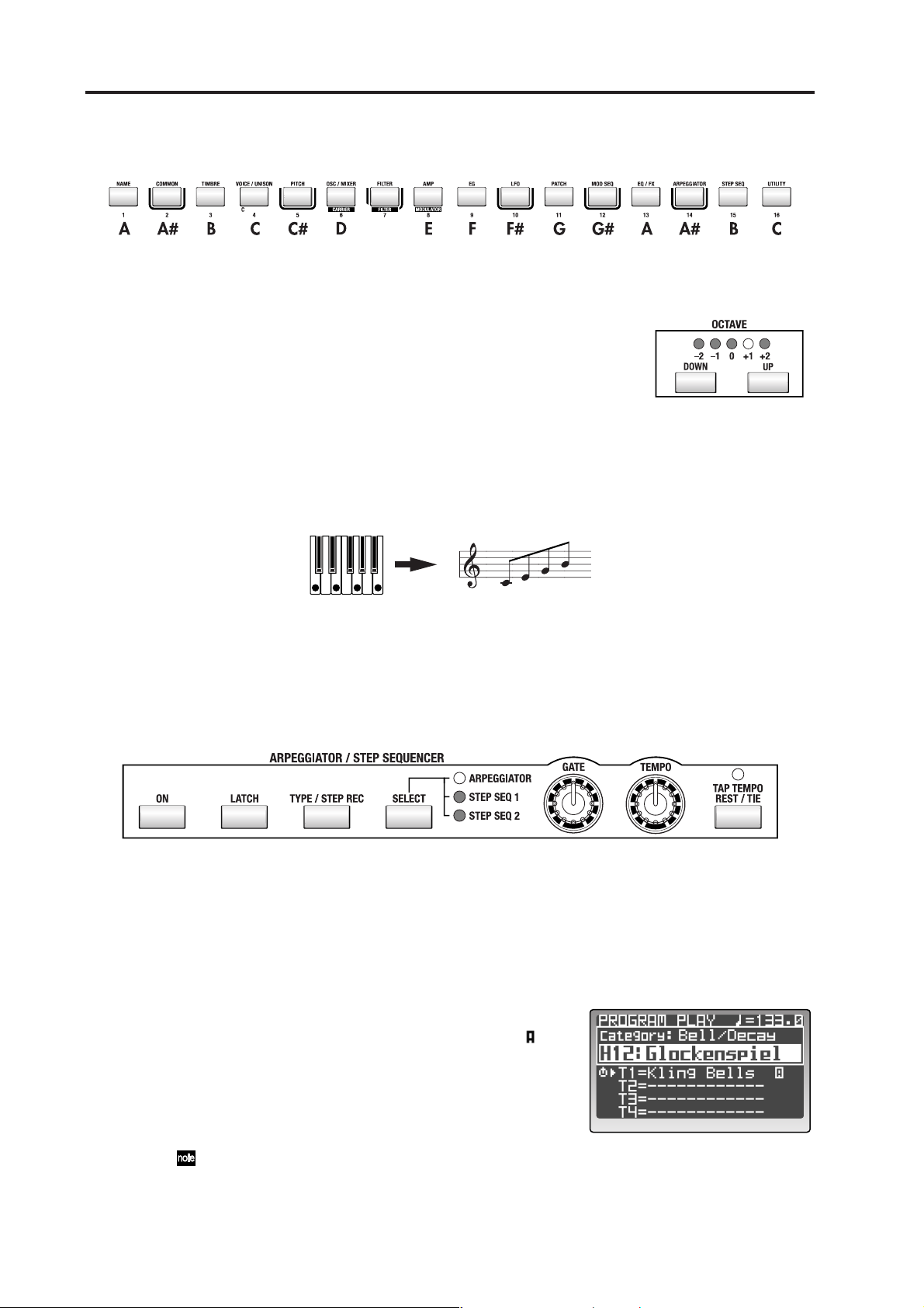
Quick Start
2 Play the RADIAS using the 16KEYS [1]–[16] keys.
The current program will play. The 16KEYS [1]–[16] keys are assigned to the following pitches.
Changing the octave
You can change the range of the 16KEYS [1]–[16] keys by octaves, with a maximum range of a maximum of two octaves up or two octaves down. The LED
indicator will show the currently selected octave.
Use the OCTAVE [UP] button or [DOWN] button to shift the pitch
in one-octave steps.
Arpeggiator
The arpeggiator detects the notes being played on the keyboard, and automatically plays these notes one at
a time in a variety of arpeggiated styles (i.e., arpeggiates the notes of the chord).
D#
Hold down a chord on the keyboard, and it will sound as shown at right (Arpeggio type: Up)
On the RADIAS, you can select one of six arpeggio types, and also specify the duration and spacing of each
note in the arpeggio.
Assigning the arpeggiator to a sound
Here’s how to assign the arpeggiator to a specific timbre in a program.
1 Select a program where the arpeggiator isn’t already assigned to a timbre.
Try using a simple bell-type sound with a short sustain.
2 Use the TIMBRE SELECT [1]–[4] buttons to choose which timbre(s) will be played by the
arpeggiator.
The button of the selected timbre will blink.
3 Use the ARPEGGIATOR/STEP SEQUENCER
[SELECT] button to select ARPEGGIATOR.
When the arpeggiator is assigned to a timbre, the “ ”
indication will appear at the right of the timbre name.
22
4 Use the ARPEGGIATOR/STEP SEQUENCER [ON]
button to turn the arpeggiator on.
The button will light when the arpeggiator is on.
If a step sequencer is assigned to another timbre, the
step sequencer will also be turned on at this time.
Page 29
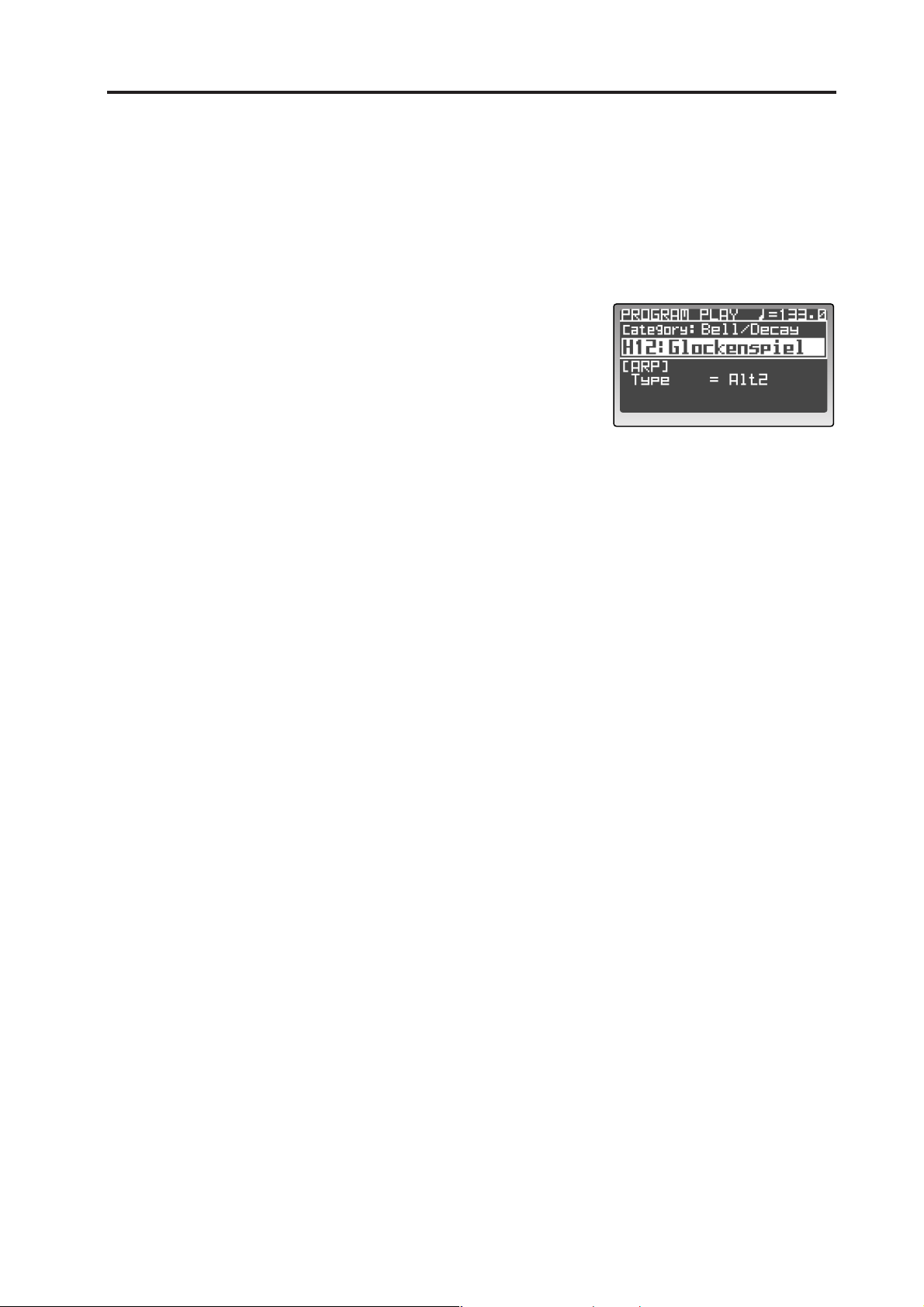
Arpeggiator
5 Hold down a chord on the keyboard.
You will hear the arpeggio pattern.
6 Turn the Latch function on.
Press the [LATCH] button. When Latch is on, the latch button will light.
With the Latch on, the arpeggio will continue playing even after you remove your hand from the
keyboard. With the Latch off, the arpeggio will stop playing when you remove your hand from
the keyboard. Pressing the [LATCH] button will turn the Latch feature on and off.
7 Use the [TYPE/STEP REC] button to select the arpeg-
gio type.
The display will show the arpeggio type.
The arpeggio type will change each time you press the
button.
Press the PAGE [+][–] button or [EXIT/NO] button to
return to the previous screen.
8 Use the [TEMPO] knob or the [TAP TEMPO/REST-
TIE] button to adjust the tempo.
Turn the [TEMPO] knob toward the right to speed up the tempo, or toward the left to slow down
the tempo.
You can set the tempo manually simply by tapping the [TAP TEMPO/REST-TIE] button several
times at regular intervals.
The tempo you specify is shown in the upper right of the display. The TEMPO LED will blink at
quarter-note intervals of the specified tempo.
9 Turn the [GATE] knob to adjust the duration of the notes.
Turning the knob toward the right will lengthen the duration of the notes, and turning it toward
the left will shorten the duration.
Other settings for the arpeggiator
The arpeggiator also allows you to set the Octave, Key Sync, Scan Zone, Resolution, Swing, and whether or
not each step will be heard. For details on these parameters, refer to p.47 “Editing the arpeggiator,” and p.96
“4. ARPEGGIATOR.”
23
Page 30
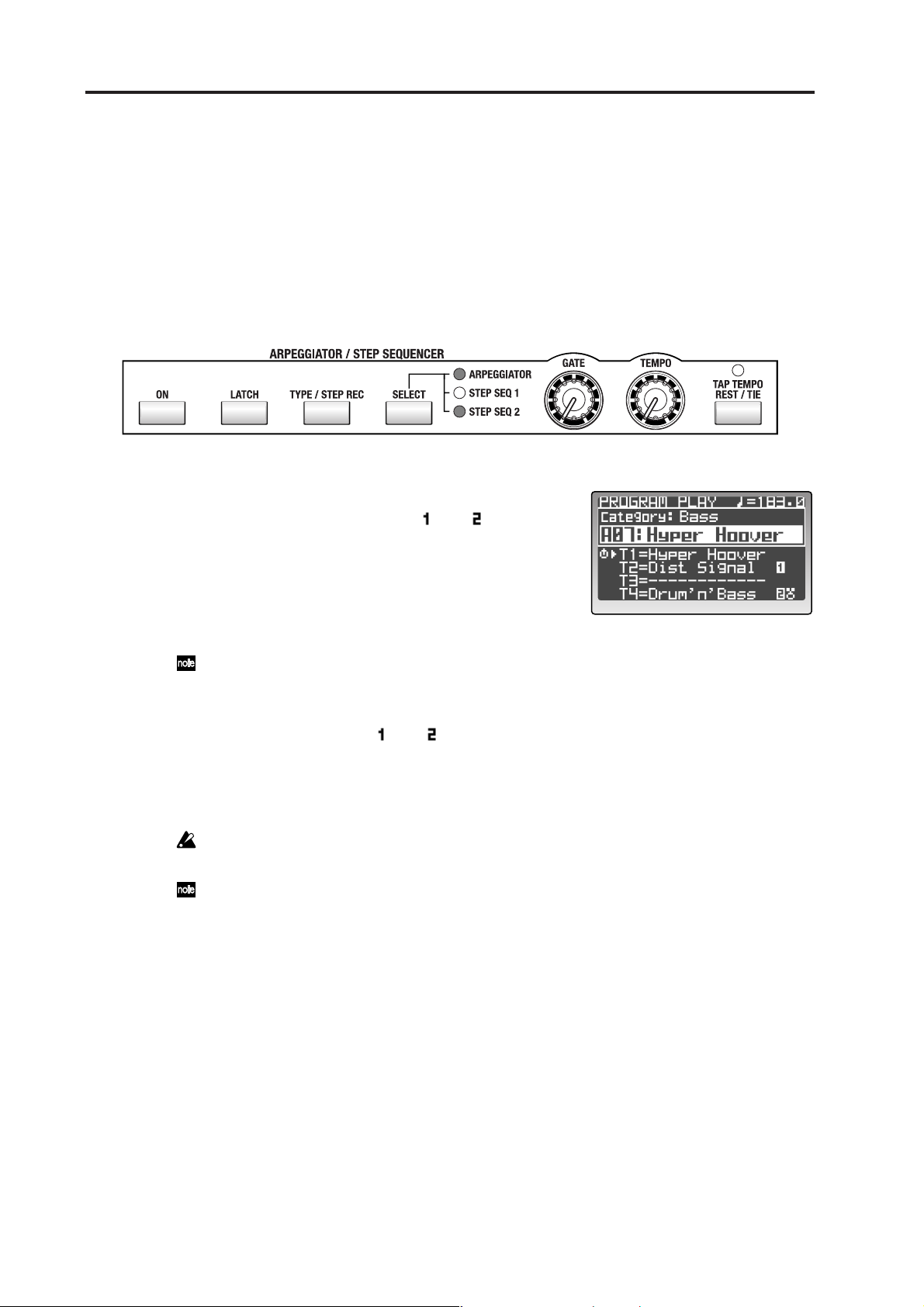
Quick Start
Step Sequencer
You can use the two step sequencers to record and play back a phrase or pattern.
This section explains how to play a step sequence and make some simple edits. For details on recording and
editing, refer to p.50 “Step sequencer recording and editing.”
Playing a program using the step sequencer
Some of the factory programs already contain sequence data. For this example, we can select and play one
of these programs.
1 Select a program from the “Arp/Seq” category that
has a step sequence assigned to one of the timbres.
If a step sequencer is assigned, a “ ” or “ ” will be
displayed at the right of the timbre name.
☞p.21 “Selecting programs by category”
2 If the ARPEGGIATOR/STEP SEQUENCER [ON] but-
ton is not lit, press the [ON] button to make it light.
The button will light when turned on.
If the arpeggiator is assigned to another timbre, the arpeggiator will also be switched on/off at this
time.
3 Press the TIMBRE SELECT [1]–[4] button of the timbre being played by the step sequencer.
Select a timbre which has “ ” or “ ” displayed to the right of the timbre name. The selected timbre button will blink.
4 Hold down a key on the keyboard.
The step sequencer will begin playing.
If the step sequencer does not begin playing, try playing other notes of the keyboard. Some programs may limit the range of notes that triggers the step sequencer.
If you are playing the RADIAS on its own without connecting its dedicated keyboard, you can set
the 16KEYS [SELECT] button to KEYBOARD, and use the 16KEYS [1]–[16] to make the step sequencer play.
Other settings for the step sequencers
In addition to the settings mentioned above, you can link step sequencers 1 and 2, adjust the length of the
steps, specify the “Run Mode,” transposition, scan zone, resolution, swing, the gate time for each step, velocity and the note numbers that will be played. For details on these parameters, refer to p.50 “Step sequencer recording and editing,” and p.99 “5. Step Sequencer.”
24
Page 31

Modulation Sequencer
Modulation Sequencer
The modulation sequencer applies time-varying change to sound parameters in a way similar to an analog
sequencer. When the sound is played, it will change over time according to the values stored for each of the
sixteen steps. Since three modulation sequencers are provided for each timbre, this can be used to create very
complex sounds.
Playing a program that uses the modulation sequencer
All factory programs already contain modulation sequencer data. we can select and play one of these programs.
1 Select a program from the “Motion” category that uses modulation sequencing.
If modulation sequencing is being used, the MOD
SEQUENCER [ON] button will be lit. Keep in mind,
this button will only reflect the Mod Sequencer status if
the selected timbre; you may find it necessary to use the
TIMBRE SELECT [1]–[4] buttons to locate the timbre
using Mod Sequencing.
☞p.21 “Selecting programs by category”
In some programs, the modulation sequencer, the arpeggiator, and both step sequencers may be turned on.
Therefore, you may wish to mute the other timbres by
holding down the [EXIT/NO] button and pressing their
respective TIMBRE SELECT [1]–[4] button.
2 Play the keyboard.
The sound of the program will change over time as the
modulation sequence runs.
3 Use the [TEMPO] knob or [TAP TEMPO REST/TIE] button to adjust the speed at which the
sound changes.
The speed of the changes produced by the modulation sequencer can be adjusted in the same way
as the arpeggiator or step sequencers.
☞p.22 “Assigning the arpeggiator to a sound”
4 Use the MOD SEQUENCER [SELECT] button to
select a modulation sequencer (MOD1–MOD3).
The LED of the selected sequence will light, and the
assigned parameter will appear in the display.
You can’t change the parameter that’s assigned to the
modulation sequencer in the Program Play mode. To assign the parameter, use the Program Edit mode P12:
MOD SEQ – SEQ1–SEQ3 tab pages (☞p.92 “P12 MOD
SEQ (Modulation Sequencer)”).
25
Page 32

Quick Start
Audio In
You can use the RADIAS’ filters, amp, and effects to process an external audio source in the same way as an
internal oscillator waveform. The following section describes how to connect a CD player or an MD player
and modify the incoming audio.
Processing an external audio source
Turn off the power of both devices before you connect any external device. You should also turn the RADIAS’ AUDIO IN [1/INST] and [2/VOICE] knobs to the 0 position.
1 Connect the output jacks of your external audio device to the RADIAS’ INPUT jacks.
If you’re connecting in stereo, connect to both the INPUT 1 and INPUT 2 jacks.
☞p.18 “5. Connecting the audio inputs – INPUT jacks”
The INPUT jacks are monaural phone plugs. If necessary, use the appropriate conversion adaptor
for the cables you’re using.
2 Turn on the power of both devices.
3 Select a program in the Program Play mode.
We recommend that you select an initialized program (program
name is “Init Program”) from the P bank.
4 Use the OSCILLATOR 1 [WAVE] button to select AUDIO IN.
5 Input an audio source from your external audio device, and use
the AUDIO IN [1/INST] or [2/VOICE] knobs to adjust the input
level.
Adjust the input level so that the AUDIO IN LEDs do not light red.
6 Play the keyboard.
The audio source will be processed using the current settings, and will be sent to the outputs as
you continue playing.
7 Use the knobs and buttons of the front panel to process the audio source that is being input.
For details on how to set the various parameters, refer to p.37 “Program parameter editing.”
Pitch-related parameters have no effect on an audio source from the INPUT jacks.
26
Page 33

Vocoder
Here’s how to select one of the RADIAS’ vocoder programs and try out some of the vocoder function.
On the front panel, functions labeled in white characters on a dark background are vocoder parameters.
Playing a vocoder program
Before you connect a mic, set the AUDIO IN [2/VOICE] knob to the 0 position.
1 Connect the mic that came with your RADIAS to the CONDENSER MIC jack.
☞p.18 “5. Connecting the audio inputs – INPUT jacks”
2 Set the rear panel [SOURCE SELECT] switch to CONDENSER MIC.
☞p.14 “Rear panel”
3 Turn on the power of the RADIAS.
4 Select a program from the vocoder category.
The TIMBRE SELECT [VOCODER] button will be lit for
programs that use the vocoder. In addition, there will
be a “V” symbol at the right of the program name
shown in the display.
Some of the factory programs do not use an external
input as the modulator source for the vocoder. In this
example we’re trying to use the vocoder with the connected mic, so select a program that uses the external
input. How can you tell? Choose a vocoder program
that does not produce sound when you play the keyboard (without talking into the microphone).
☞p.21 “Selecting programs by category”
Vocoder
5 Press the [VOCODER] button so that the front panel knobs and buttons will control the
vocoder.
6 Speak or sing into the mic, and use the AUDIO IN 2 knob to adjust the input level.
Adjust the level so that the LED above the AUDIO IN 2 knob does not light red.
You can turn up the AMP [DIRECT LEVEL] knob to hear the direct sound from the microphone.
This lets you make adjustments while listening to the incoming signal.
7 While you speak or sing into the mic, play the keyboard.
The sound processed by the vocoder effect will be output.
If you have difficulty hearing the result, try adjusting the MIXER [SRC1] knob.
If you are playing the RADIAS on its own without connecting its dedicated keyboard, you can set
the 16KEYS [SELECT] button to KEYBOARD, and use the 16KEYS [1]–[16] to play the sound.
27
Page 34

Quick Start
Playing a Drum Kit – Drum Play mode
The RADIAS provides thirty-two drum kits, each consisting of sixteen drum instruments. You can assign
these instruments to note numbers and play them from the keyboard, and one timbre in each program can
be assigned a drum kit.
In the Drum Play mode you can play drum kits directly from the keyboard.
Here’s how to select and play a drum kit.
1 Press the [DRUM] button.
The display will indicate that you’re in the Drum Play
mode.
From top to bottom, the display shows the number and
name of the drum kit, and the name, note number, and
group of the selected drum instrument.
2 Use the [PROGRAM/VALUE] dial to select a drum
kit.
Turn the dial to select one of the thirty-two drum kits.
3 Play the keyboard.
The drum instrument assigned to each note will sound. In the factory-set drum kits, drum instruments are assigned to the C2–D#3 keys.
The display will indicate the name, note number, and group of the drum instrument you played.
You can also play the drum kit using 16KEYS [1]–[16].
In the Drum Play/Edit modes, each drum instrument will sound on the global MIDI channel.
In the Drum Play/Edit modes, the operation of the effects, arpeggiator, and step sequencer will behave according to the timbre that was assigned to a drum kit in the program that was selected when
you hit the [DRUM] button to enter the Drum Play mode. If no drum kit was assigned to the program, the settings of initial program will be used. In this case, you will only be able to change the
on/off switch settings for the assigned effect or the arpeggiator.
28
Page 35

Editing
A program consists of a large number of parameters; the names and synth parameters of all four timbres, the
program common settings such as program name, vocoder settings etc. If you want to create a program
“from scratch,” you’ll need to understand what each of these parameters does. An easier way to get started
is to start by choosing one of the factory programs or timbre templates and editing the parameters to understand what they do.
Basic editing procedure
This section explains the basic operations for editing and setting parameters.
You can edit the sound of a program in either the Program Play mode or in the Program Edit mode.
If a drum kit is assigned to a program, you can edit those drum sounds in the Drum Play mode or in the
Drum Edit mode.
Editing in the Program Play mode
In the Program Play mode you can select and play programs, and you can also use the front panel knobs and
buttons to edit the sound of the program as you play, for example by raising the filter cutoff frequency or by
making the attack slightly slower.
Selecting the timbre to edit
If the program consists of more than one timbre, here’s how to select the timbre to be edited.
1 Use the TIMBRE SELECT [1]–[4] buttons to select the
timbre you want to edit.
The button for the selected timbre will blink. A symbol is shown in front of the timbre name in the display.
The front panel knobs and buttons and the timbre
parameters shown in the display will apply to the timbre that is selected.
When you switch programs (or perform a Program
Dump), the lowest-numbered active timbre is selected.
2 Operate the button or knob for the parameter you want to edit.
Each time you press the button, the function assigned to that button will switch between on and
off; or pressing the button will advance through a list of available values for that parameter. The
button or LEDs will light to indicate the current status.
The parameter for a knob can be adjusted just like an analog control, as shown by the markings
around the knob.
In the case of both knobs and buttons, the ORIGINAL VALUE LED will light when the current setting matches the value stored in the program.
Editing in the Program Edit mode
If you want to edit a parameter that is not assigned to a knob or button, or if you want to view the parameter
values in the display while you edit them, you’ll need to enter the Program Edit mode.
Entering the Program Edit mode
1 From the Program Play mode, press the [EDIT/YES]
button.
This will open up the Program Edit mode.
From the top down, the display shows the page number
and page name, and the parameter names and values.
29
Page 36

Editing
Selecting the timbre to edit
If the program consists of more than one timbre, here’s how to select the timbre you want to edit.
2 Use the TIMBRE SELECT [1]–[4] buttons to select
the timbre you want to edit.
The button for the selected timbre will blink. The
front panel knobs and buttons and the timbre parameters shown in the display will apply to the timbre
that is selected.
If you want to edit the vocoder, press the [VOCODER] button.
You can’t select a timbre that’s currently off (a timbre whose button is unlit). To turn on a timbre
that’s currently turned off, hold down the [EXIT/NO] button while selecting the timbre using the
TIMBRE SELECT [1]–[4] buttons. This can also be used to turn any timbre off.
Depending on the Program Edit mode P02–1: COMMON – PROG tab page “PanelEdt” (panel edit)
setting, the timbre you select here may not necessarily match the front panel knobs and buttons
(☞p.75 “PanelEdit”).
Selecting pages and tab pages
The Program Edit mode consists of multiple pages. To select a page you can use the PAGE [+][–] buttons or
the 16KEYS [1]–[16].
Press the PAGE [+] or [–] button.
You will step through the pages or tab pages one at a
time.
If a page contains more than one tab page, a symbol
is shown in the lower right of the page. Press the PAGE
[+] button to step through the tab pages.
Use the 16KEYS [SELECT] button to choose PAGE,
and press a 16KEYS [1]–[16] key.
This method lets you move directly to the page containing the parameter you want to edit.
The following table shows how the 16KEYS [1]–[16] keys correspond to the various pages. If a
page contains more than one tab page, you can step through the tab pages by repeatedly pressing
the corresponding [1]–[16] key.
[1]–[16] key Page Tab pages
[1] P01: NAME PROG TIMBRE
[2] P02: COMMON PROG DRUM E.F
[3] P03: TIMBRE TMBR OUT ZONE MIDI CC-A CC-B
[4] P04: VOICE VOICE UNISON
[5] P05: PITCH
[6] P06: OSC/MIXER OSC1 OSC2 MIXER
[7] P07: FILTER FILTER1 FILTER2
[8] P08: AMP
[9] P09: EG EG1 EG2 EG3
[10] P10: LFO LFO1 LFO2
[11] P11: PATCH P1 P2 P3 P4 P5 P6
[12] P12: MOD SEQ COMN SEQ1 SEQ2 SEQ3
[13] P13: EQ/FX EQ IFX1 IFX2 MFX
[14]
[15] P15: STEP SEQ1/2 COMN TRIG STEP COMN TRIG STEP
[16] P16: UTILITY PROG TMBR MOD FX ARP
P14: ARPEGGIATOR
COMN TRIG STEP
30
Page 37

Selecting and editing a parameter
1 Use the cursor buttons to select the parameter you
want to edit.
When you press one of the cursor button, the cursor
will move to the next parameter, and it will be highlighted in the display.
If there are numerous parameters, a ▼ symbol is shown
at the right edge of the page, indicating that you can
access additional parameters below those shown in the
screen by scrolling. As you press the cursor [†/®] button to move the cursor downward, the additional
parameters will appear. When the cursor no longer moves when you press the cursor [†/®] button, you have reached the last parameter of that page.
In some cases, the setting of one parameter may affect the number or content of other parameters
in the page. A symbol is shown in front of parameters that are affected by another parameter in
this way. For example in the P04–1: VOICE – VOICE tab page if you change “Assign” from Poly to
Mono, the additional parameters “Priority” and “Trigger” will appear.
Basic editing procedure
Changing a value
1 Use the front panel knobs, buttons, or the [PROGRAM/VALUE] dial to
change a value.
In generally, you will use the front panel knobs and buttons.
You can use the [PROGRAM/VALUE] dial if there is no knob or button for
that parameter, or if you want to make fine adjustments to the value. Turning the dial will increment or decrement the value in steps of one.
You will also use the [PROGRAM/VALUE] dial to specify a program when
writing a program, and when entering a name for a program.
If the Global mode P02: MEMORY page “PageJump” setting is On, operating
a knob or button in the Program Edit mode will automatically cause the display for that parameter to appear. With the factory settings this is turned On (☞p.115
“PageJump”).
Returning to the Program Play mode
Press the [EXIT/NO] button or the [PROGRAM] button.
You will return to the Program Play mode.
31
Page 38

Editing
Compare function
While editing a program, you can compare the edits you have made to the original program or timbre.
1 Press the [COMPARE] button.
The display will indicate “Compare.”
Play the keyboard to hear the sound as it was before
you began editing it.
You can’t operate the knobs or buttons in the “compare”
state.
2 Press the [EXIT/NO] button.
The display will return to its previous state. When you
play the keyboard you will once again hear the edits you have already made, and you can continue editing.
Saving an edited program
When editing a sound, you need to save the changes you have made if you want to keep them. If you don’t
save your edits, they will be lost the next time you select another program, load a template, or turn the RA-
DIAS off. If you want to keep your changes, you must use the Write operation.
In order to write data, the Global mode P02: MEMORY page “Protect” setting must be Off. From
the factory, this setting is On (☞p.115 “Protect”).
Programs can be written while in the Program Play mode or the Program Edit mode, drum kits or drum instruments can be written in the Drum Play mode or the Drum Edit mode, and global parameters can be written in the Global mode.
1 In the Program Play mode or the Program Edit mode,
press the [WRITE] button.
The “Write dialogue” dialog box will appear.
2 Specify the write-destination program number in the
“To” field.
3 Press the [WRITE] button or the [EDIT/YES] button to
execute the Write operation.
The data will be written, and you will return to the
mode in which you were.
If you decide to cancel the Write operation, press the [EXIT/NO] button.
Never turn off the power while data is being written. The data may be damaged if you do so.
You can use the cursor [π/√] button to select “Write,” and then choose one of the following three
types of content to write.
Program: Save the program.
Formant: Save the formant motion data.
Prg&Frmnt: Save both the program and the formant motion data.
If there is no newly recorded formant option data (☞p.58 “Recording formant motion data”), the
“Write” field will show Program. If there is newly recorded formant motion data, “Write” will
show Prg&Frmnt.
32
Page 39

Basic editing procedure
Loading other timbre sounds/The Template function
The Template function can be a real convenience when you’re creating a program sound or an effect. You
can load a program template that is close to the type of sound you have in mind, and then edit it to create a
program much more easily than working from scratch. You can also store sounds and effect settings you created as template data for later use.
You can load templates while you’re in the following pages.
Mode Page Tab page Type of template
Program Edit mode
Drum Edit mode P02: COMMON DRUM MAP Drum instrument setting template
The RADIAS makes no distinction between timbre templates and drum instrument templates, and
they are held in the same memory area, you can exchange data between them.
When you load a template, edited data that has not been written will be lost. If you want to keep
the data you’re editing, you must first write the data before you load the template.
Loading other timbre settings or templates
Here’s how to load other timbre settings or insert effect templates.
P03: TIMBRE TMBR Timbre setting template
P13: EQ/FX IFX1, IFX2, MFX Effect setting template
Loading other timbre sounds
1 Go to the Program Edit mode P03–1: TIMBRE –
TMBR tab page.
2 Use the cursor [π/√] button to select the timbre slot
or location where the timbre will be loaded.
You can’t select a template for a timbre that is turned off.
3 Use the [PROGRAM/VALUE] dial to select a timbre.
In addition to loading one of the timbre, you can also
load any of the active timbres form any of the programs stored in the RADIAS. As you turn the
[PROGRAM/VALUE] dial to the right, you will first see the active timbres starting with the currently selected program, and then the templates (“Tmp001:Init P”, etc.). When you stop turning
the dial, the timbre or template shown in the display will be loaded to that location.
In the Drum Edit mode (Drum Edit mode P02–1: COMMON, DRUM MAP page), use the 16KEYS
[1]–[16] keys to select the instrument into which you want to load a template, and then use the cursor buttons to move the cursor to “Load:” in the top line. (☞p.61 “Loading and editing an another
drum instrument or drum instrument template”)
In the Drum Edit mode, first the drum kit instruments and then the templates are displayed.
Loading an insert effect template
1 Go to the Program Edit mode P13–2: EQ/FX – IFX1 tab page.
2 Use the cursor [π/√] button to move the cursor to “Load:”.
3 Use the [PROGRAM/VALUE] dial to select a template.
The template you select will be loaded, and the parameters of the insert effect will be rewritten by
the settings of the template.
33
Page 40

Editing
Making a template
Here’s how to make a timbre template. Templates you make can be loaded in the same way as the factory
templates. You will use the P16: UTILITY page to make templates. (☞p.107 “P16 UTILITY,” p.113 “P16
UTILITY”)
1 Select a program that uses a timbre you want to store as a template, and enter the Program Edit
mode.
2 Use the TIMBRE SELECT [1]–[4] buttons to select the timbre that you want to store as a tem-
plate.
3 Go to the P16–2: UTILITY – TMBR tab page.
4 In “Edit,” choose “MakeTemplate.”
5 In “Dest,” specify the destination number in which
you want to store the template.
6 In “Name,” specify a name for your new template.
To enter a name for the template, use the cursor buttons
to move the cursor and use the [PROGRAM/VALUE]
dial to specify each character.
☞p.35 “How to assign a name”
7 Change “Sure?” to “Press [YES],” and then press the [EDIT/YES] button.
The “Sure?” field will indicate Complete. The template has been stored.
Assigning a name
The RADIAS lets you assign names to the following types of data.
If you fail to execute the Write operation after you’ve entered a name, the name will revert to its
prior state. For details on writing, refer to p.32 “Saving an edited program.”
• Programs
The program name is displayed in the Program Play mode.
To enter a program name, use the Program Edit mode’s P01: NAME page (☞p.74 “P01–1: PROG (Program Name)”).
•Timbres
Timbre names are displayed along with the program name in the Program Play mode.
To enter a timbre name, use the Program Edit mode’s P01: NAME page (☞p.74 “P01–2: TIMBRE (Timbre
Name)”).
Because the same drum kit may be used in many programs, you can’t edit the timbre name if
you’ve assigned a drum kit. Drum kit names are created in the Drum Edit mode (as described below).
• Categories
Category names are displayed along with program names in the Program Play mode.
To enter a category name, use the Global mode’s P10: CATEGORY NAME page (☞p.120 “P10–1: CATEGORY NAME”).
34
• Drum kits
Drum kit names are displayed in the Drum Play mode.
In the Drum Play mode you must first select the drum kit whose name you want to enter.
To enter a drum kit name, use the Drum Edit mode’s P01: NAME page (☞p.111 “P01–1: KIT (Drumkit
Name)”).
• Drum instruments
In the Drum Play mode you must first select the drum instrument whose name you want to enter.
Page 41

Basic editing procedure
To enter a drum instrument name, use the Drum Edit mode’s P01: NAME page (☞p.111 “P01–2: INST
(Drum Instrument Name)”).
•Templates
Template names are displayed when you are loading templates.
You can enter a template name when creating a template in the P16: UTILITY page of the mode in which
you’re creating the template (☞p.107 “P16 UTILITY,” p.113 “P16 UTILITY”).
How to assign a name
Here we will use the example of assigning a name to a program. You can use the same procedure to assign
names other than program names. Before you proceed, use the Program Play mode to select the program
whose name you want to edit.
Using the cursor buttons and the [PROGRAM/VALUE] dial
1 Go to the Program Edit mode P01–1: NAME – PROG
tab page.
2 Use the cursor buttons to move the cursor to the char-
acter you want to change.
3 Use the [PROGRAM/VALUE] dial to choose the
desired character.
4 Repeat steps 2–3 to edit the name of the program.
You can specify a program name of up to twelve characters.
Using the [EDIT/YES] button and the sixteen knobs
With the P01–1: NAME – PROG tab page displayed, you can use the front panel [EDIT/YES] button and the
sixteen knobs to edit the program name as follows.
Hold down the [EDIT/YES] button and turn knobs 1–12 (PORTAMENTO [TIME] – LFO2
[FREQ]) to change the first through twelfth character of the name.
Hold down the [EDIT/YES] button and turn knob 13 (EQ [LO]) to choose uppercase alphabetical
characters for the selected character.
Hold down the [EDIT/YES] button and turn knob 14 (INSERT FX [EDIT1]) to choose lowercase
alphabetical characters for the selected character.
Hold down the [EDIT/YES] button and turn knob 15 (INSERT FX [EDIT2]) to select numerals
for the selected character.
Hold down the [EDIT/YES] button and turn knob 16 (MASTER FX [EDIT]) to select symbols
(including a space) for the selected character.
Deleting a character
1 Use the cursor buttons to move to the character you want to delete.
2 Hold down the [EDIT/YES] button and press the cursor [π/√] button.
The selected character will be deleted.
Inserting a character
1 Use the cursor buttons to move to the location at which you want to inset a character.
2 Hold down the [EDIT/YES] button and press the cursor [†/®] button.
A character will be inserted at the selected location. The inserted character will be the character
that was most recently deleted. The first time you insert, this will be a space.
35
Page 42

Editing
Assigning a category
When you specify a program name, you can also assign that program to a category. If you assign an appropriate category to each program, you’ll be able to find programs more efficiently (☞p.21 “Selecting programs by category”).
1 Go to the Program Edit mode P01–1: NAME – PROG
tab page.
2 Use the cursor buttons to move the cursor to “Cate-
gory.”
3 Use the [PROGRAM/VALUE] dial to select the cate-
gory you want to assign.
36
Page 43

Program parameter editing
Program parameter editing
Synth parameter editing
This section explains how to edit the synthesis parameters that make up an individual timbre.
The following section assumes that you have started by pressing the front panel TIMBRE SELECT [1] button
to select timbre 1 as the object of editing, and that you are in the Program Edit mode.
You must press the [WRITE] button to write the program if you want to save the results of your
editing. If you don’t Write your changes, they will be lost.
Changing the voice assign mode
Here you can set the timbre to play in a monophonic or polyphonic style. Selecting mono will cause other
“mono-related” parameters to appear.
1 Go to the P04–1: VOICE – VOICE tab page.
2 In “Assign,” specify how the timbre will be sounded.
Choose Poly if you want to be able to play chords, or
Mono if you want to play only single notes.
3 If “Assign” is set to “Mono,” you can also specify
“Priority” and “Trigger.”
“Priority” specifies the key that will be given priority
when you hold down more than one key at a time.
“Trigger” specifies how subsequent notes will be triggered when you play the next note before
releasing the previously played key.
If you want to get a richer sound, use the front panel [UNISON] button to turn on the Unison function. This function stacks multiple notes together. In the P04–2: VOICE – UNISON tab page you can
specify the number of notes that will be stacked. (☞p.80 “P04–2: UNISON”)
Oscillator settings
Here’s how to set the oscillator parameters that are the basis of the timbre.
Oscillator 1 settings
1 Use the OSCILLATOR 1 WAVE buttons to select the waveform for
oscillator 1.
Use these buttons to step through the waveforms. The LED of the
selected waveform will light. You can choose one of nine different
waveforms, including an external audio input (AUDIO IN).
2 Use the OSCILLATOR 1 [OSC MOD] button to select the type of
modulation being applied to oscillator 1.
The type will switch each time you press the button, and the LED for
the selected modulation type will light. You can choose one of four
modulation types.
If you’ve selected FORMANT, NOISE, SYNTH PCM, DRUM PCM, or
AUDIO IN as the waveform, the only available modulation type will
be WAVEFORM.
3 Use the [CONTROL 1] and [CONTROL 2] knobs to specify the
waveform parameters.
The parameters that are controlled by the [CONTROL 1] knob and
[CONTROL 2] will depend on the waveform and the modulation type
you’ve selected.
For details on the oscillator parameters, refer to p.81 “P06–1: OSC 1.”
37
Page 44

Editing
Oscillator 2 settings
1 Use the OSCILLATOR 2 [WAVE] button to select the waveform of
oscillator 2.
The waveform will change each time you press the button, and the
LED of the selected waveform will light. You can choose one of four
different waveforms. The most common way to use this is to select the
same waveform as oscillator 1, and change its pitch slightly to create a
rich sound.
2 Use the OSCILLATOR 2 [OSC MOD] button to select the modula-
tion type for oscillator 2.
The type will switch each time you press the button, and the LED for
the selected modulation type will light. You can choose one of three
modulation types.
3 Use the [SEMITONE] knob to adjust the pitch of oscillator 2 in
semitone steps.
Some of the more common ways to set this parameter is to lower the
pitch by one octave (–12) or two octaves (–24) relative to the pitch of
oscillator 1. Vintage analog synthesizer players would sometimes set
the oscillators a fourth (+5) or fifth (+7) apart in pitch.
4 Use the [TUNE] knob to adjust the pitch of oscillator 2.
You can produce a richer sound by slightly changing the pitch to create a detuned effect.
Adjusting the volume of each oscillator
1 Use the MIXER [OSC 1] knob to adjust the volume of oscillator 1.
2 Use the MIXER [OSC 2] knob to adjust the volume of oscillator 2.
3 Use the MIXER [NOISE] knob to adjust the volume of the noise generator.
Filter settings
Selecting the routing
1 Use the [ROUTING] button to select the filter rout-
ing.
Each time you press the button, the routing of filters 1
and 2 will change. The LED of the selected routing
will light. You can choose one of four different routings. If you choose SINGLE, only filter 1 will be used.
38
Filter 1 settings
1 Use the FILTER 1 [TYPE] knob to select the type of
filter being used by filter 1.
You can adjust the knob to obtain intermediate characters between these filter types. The filter type will
have a major effect on the character of the sound.
Page 45

Program parameter editing
2 Use the FILTER 1 [CUTOFF] knob to adjust the cutoff frequency of filter 1.
Turning the knob toward the right (increasing the value) will make the sound brighter.
3 Use the FILTER 1 [RESONANCE] knob to adjust the resonance of filter 1.
Turning the knob toward the right (increasing the value) will boost the region near the cutoff frequency.
The effect of resonance is also greatly affected by the filter type and cutoff frequency setting.
Depending on the cutoff frequency and the input sound, raising the resonance value may cause distortion.
4 Use the FILTER [SELECT] button to select FILTER 1, and use the [EG
1 INT] knob to adjust the depth of the effect that EG1 will have on
the cutoff frequency of filter 1.
If you turn the knob toward the right of the center position (“+” values), the EG will move the filter in the positive direction (i.e., if the filter type is LPF, the sound will become brighter).
If you turn the knob toward the left of the center position (“–” values),
the EG will move the filter in the negative direction (i.e., if the filter
type is LPF, the sound will become darker).
Filter 2 settings
1 Use the FILTER 2 [TYPE] button to select the type of filter being used
by filter 2.
The filter type will change each time you press the button, and the LED
of the selected filter type will light. The filter type will have a major
effect on the character of the sound.
If the FILTER 1 [ROUTING] button has been set to SINGLE, filter 2 is
not used and cannot be edited.
2 Use the FILTER 2 [CUTOFF] knob to adjust the cutoff frequency of
filter 2.
Turning the knob toward the right (increasing the value) will make the
sound brighter.
3 Use the FILTER 2 [RESONANCE] knob to adjust the resonance of
filter 2.
Turning the knob toward the right (increasing the value) will boost the
region near the cutoff frequency.
The effect of resonance is also greatly affected by the filter type and
cutoff frequency setting.
Depending on the cutoff frequency and the input sound, raising the resonance value may cause distortion.
4 Use the FILTER [SELECT] button to select FILTER 2, and use the [EG 1 INT] knob to adjust the
depth of the effect that EG1 will have on filter 2’s cutoff frequency.
If you turn the knob toward the right of the center position (“+” values), the EG will move the filter in the positive direction (i.e., if the filter type is LPF, the sound will become brighter).
If you turn the knob toward the left of the center position (“–” values), the EG will move the filter
in the negative direction (i.e., if the filter type is LPF, the sound will become darker).
39
Page 46

Editing
Creating time-varying change in the tone (EG1)
EG1 applies time-varying change to the cutoff frequency (the “Cutoff” of FILTER 1 or FILTER 2).
EG1 applies the same effect to filter 1 and filter 2.
You can edit the virtual patching so that EG1 will apply modulation to other parameters as well.
Note on
b
a
a: Attack Time c: Sustain Level
b: Decay Time d: Release Time
Note off
c
d
Time
Envelope settings for tonal change
1 Use the EG 1 [ATTACK] knob to adjust the attack time (the time over which the tone changes
during the beginning of the note).
Turn the knob toward the right to make the tone change more slowly, or turn it toward the left to
make the tone change more quickly.
If turning this knob does not produce results, try adjusting the FILTER [EG 1 INT] knob or make
sure that the MOD SEQUENCER [SELECT] button is set to make EDIT lit. If an LED other than
EDIT is lit, you can’t edit the EG or LFO. (These knobs are used to edit the modulation sequencer
data.)
2 Use the EG 1 [DECAY] knob to adjust the decay time (the time over which the tone falls from
its peak).
Turning the knob toward the right (i.e., increasing the value) will make the tone change more
slowly until it reaches a stable tone (if sustained).
3 Use the EG 1 [SUSTAIN] knob to adjust the sustain level (the brightness during the sustain).
The brightness produced by the [SUSTAIN] knob will depend on the FILTER [EG 1] knob setting.
4 Use the EG 1 [RELEASE] knob to adjust the release time (the time over which the tone falls
after you release the key).
Turning the knob toward the right will produce a slower change in tone, and turning it toward the
left will make the tone change quickly.
40
Page 47

Timbre output settings
Timbre output settings
1 Use the AMP [LEVEL] knob to adjust the volume of the timbre.
2 Use the AMP [PAN] knob to adjust the panning (position in the stereo field) of
the timbre.
If this knob is in the center position (CNT), the sound will be sent equally from the
left and right outputs (center).
Applying Drive or Wave Shaping
1 Use the [DRIVE/WS] button to select Drive or Wave Shaping.
If you select Drive, the DRIVE LED will light. If you select Wave Shaping, the WS
LED will light.
2 Turn the [DEPTH] knob.
Turning the knob toward the right (increasing the value) will increase the effect.
Using note number (key position) to affect the volume
Program parameter editing
1 Go to the P08: AMP page.
2 Use “Key Track” to specify how the note number, or
the key’s position on the keyboard will affect the volume.
With positive (+) settings, the volume will increase as
you play above the C4 note and decrease as you play
below it.
With positive (–) settings, the volume will decrease as
you play above the C4 note and increase as you play
below it.
Creating time-varying change in the volume (EG 2)
EG2 applies time-varying change to the AMP “Level.”
You can edit the virtual patching so that EG2 will apply modulation to other parameters as well.
If you want to use the front panel knobs to adjust the EG2 parameters, use the MOD SEQUENCER
[SELECT] button to make the EDIT indicator light.
Envelope settings for volume change
1 Use the EG 2 [ATTACK] knob to adjust the time required to arrive at full volume after the key
is pressed.
Turn the knob toward the right (increase the value) to make the volume change more slowly, or
turn it toward the left (decrease the value) to make the volume change more quickly.
2 Use the EG 2 [DECAY] knob to adjust the time over which the volume falls from its peak level
to the sustained level.
Turn the knob toward the right (increase the value) to make the volume change more slowly until
it reaches a steady volume (if sustained).
41
Page 48

Editing
3 Use the EG 2 [SUSTAIN] knob to set the sustained volume level.
Turn the knob toward the right (increase the value) to make the sustain volume louder.
4 Use the EG 2 [RELEASE] knob to adjust the time required for the volume to fade away after
you release the key.
Turn the knob toward the right (increase the value) to make the release slower, or turn it toward
the left (decrease the value) to make the release faster.
For bell-type sounds, use a higher setting to create a long release.
Using keyboard dynamics to affect the volume
1 Go to the Program Edit mode P09–2: EG – EG2 tab
page.
2 Use “LvlVelInt” to specify how much the dynamics of
your playing on the keyboard will affect the volume
level change produced by EG2.
With positive (+) settings, the EG2 will produce greater
change in volume as you play more strongly.
With negative (–) settings, the EG2 will produce less
change in volume as you play more strongly.
LFO settings
An LFO (Low Frequency Oscillator) applies a cyclic change to a parameter. This will produce vibrato if applied to oscillator pitch, a wah effect if applied to filter cutoff, and tremolo if applied to amp level.
LFO2 is internally routed to the pitch of oscillator 1 (P05–1: PITCH page “Vibrato Int”). By making
virtual patch settings you can use the LFO to apply modulation to other parameters as well.
(☞p.81 “VibratInt (Vibrato Intensity)”)
Selecting the LFO waveform
1 Press the [SELECT] button.
The waveform will switch each time you press the button, and the
LED of the selected waveform will light.
The shape of the cyclic change will depend on the LFO waveform
you select.
Specifying the LFO frequency
2 Turn the [FREQ] knob.
Turning the knob toward the right (increasing the value) will speed
up the cyclic change. The speed is indicated by the interval at which
the [SELECT] button blinks.
In the P10–1: LFO – LFO1 tab page or LFO2 tab page, you can turn on the “TempoSync” parameter
so that the LFO frequency will synchronize to the tempo specified by the [TEMPO] knob. (☞p.91
“TempoSync”)
42
If you want to use the front panel knobs to adjust the LFO “Freq,” use the MOD SEQUENCER [SELECT] button to make the EDIT indicator light.
Page 49

Program parameter editing
Applying modulation to various parameters – Virtual Patch (V.PATCH)
Virtual Patch lets you assign fifteen different modulation sources to modulate various sound parameters.
If you want to use the front panel knobs to adjust the virtual patch parameters, use the MOD SEQUENCER [SELECT] button to make the EDIT indicator light.
Virtual Patch settings
1 Use the V.PATCH [SELECT] button to select a patch.
Each time you press this button you will cycle through PATCH 1–6, and the LED
of the selected patch will light.
When you press a button of the V.PATCH section while in the Program Play mode,
the virtual patch settings will appear in the display.
Press the PAGE [+][–] button or [EXIT/NO] button to return to the previous
screen.
2 Use the V.PATCH [SOURCE] button to select the modulation source (the signal
that creates the modulation).
Each press of the button will step through the available modulation sources.
For details on this parameter, refer to p.91 “P11 PATCH (Virtual Patch).”
3 Use the V.PATCH [DESTINATION] button to select the modulation destination.
Each press of the button will step through the available destination parameters.
4 Use the V.PATCH [INTENSITY] knob to adjust the amount of modulation being applied.
Turn the knob toward the right of center (“+” values) to apply modulation in the positive (+)
direction.
Turn the knob toward the left of center (“–” values) to apply modulation in the negative (–) direction.
For details on this parameter, refer to p.91 “P11 PATCH (Virtual Patch).”
Modulation Sequencers – Applying time-varying change to the sound
The Modulation Sequencers let you apply time-varying change to sound parameters in a way similar to analog sequencers of the past. A modulation sequencer stores a discreet value for each of sixteen individual
steps, and consecutively applies these values to vary the sound over time. Since three modulation sequencers are provided for each timbre, you can create sounds that change in very complex ways.
In the following example, we will select a program in which the modulation sequences are turned off, assign
modulation sequencer 1 to a timbre, and use the sixteen knobs to specify the level of modulation being applied at each step of the sequence.
Assigning a modulation sequencer to a timbre
1 In the Program Play mode, select a program in which the modulation sequencers are turned off
(the MOD SEQUENCER [ON] button will be unlit).
Choose a program in which tonal change will be easy to notice.
2 Use the MOD SEQUENCER [SELECT] button to select MOD1 (the MOD1 LED will light).
If you want to assign a parameter to SEQ2 or SEQ3, use the MOD SEQUENCER [SELECT] button
to select SEQ2 or SEQ3.
43
Page 50

Editing
SEQ COMMON parameter settings
Before you create the sequence data, use the SEQ COMMON parameters to specify the number of steps in
the sequence, and how the data will play back.
1 Go to the Program Edit mode P12–1: MOD SEQ –
COMN tab page.
2 Use “LastStep” to specify the length of the sequence
(the number of steps).
You can specify any length from 1–16 steps.
3 Use “SeqType” to specify the direction in which the
steps will play back.
In this example, choose Forward.
4 Use “RunMode” to specify how the sequence will loop.
For this example choose Loop.
5 Use “KeySync” to specify how the sequence will be reset by a note-on.
For this example choose Timbre.
6 Use “Resolutn” to specify the note length of each step, based on the tempo of the internal clock.
In this example, set the resolution to 1/16 (sixteenth note resolution). Each step of the sequence
will have the duration of a sixteenth note.
For details on this parameter, refer to p.92 “P12 MOD SEQ (Modulation Sequencer).”
Specifying the sequence data for each step
1 Go to the P12–2: MOD SEQ – SEQ1 tab page.
2 Use “Knob” to select Fil1Cut.
This assigns SEQ1 to the Filter 1 cutoff.
3 Press the MOD SEQUENCER [ON] button.
The [ON] button LED will light, and the modulation
sequencer will be turned on.
4 Use the MOD SEQUENCER [SELECT] button to
select MOD1.
5 Hold down a key so you can hear the sound, and use the sixteen knobs to specify the sequence
data for each step.
The value of each step specifies the amount of change applied to the assigned parameter. If you
want to make finer adjustments to the value, use the [PROGRAM/VALUE] dial.
44
If the MOD SEQUENCER [SELECT] button is set to EDIT, the sixteen knobs are used to edit the
sound of the program (for example, the EG or LFO parameters). If the [SELECT] button is set to
MOD1 or another modulation sequencer, the sixteen knobs are used to specify the sequence data.
The number printed below each knob corresponds to the step number within the sequence. Turn
the knob for the step you want to edit. In the P12–2: MOD SEQ – SEQ1 tab page, “Value” indicates
the value of each step.
Knobs beyond the “LastStep” value in the P12–1: MOD SEQ – COMN tab page have no effect.
(☞p.92 “LastStep”)
Page 51

Program parameter editing
You can use the above procedure to edit existing sequence data or to edit sequence data you recorded in realtime.
Recording modulation sequence data in realtime – the Motion Rec function
The Motion Rec function lets you tweak a knob in realtime, record the movements of that knob, and apply
those changes to the steps in a modulation sequencer.
In this example we’ll record movements of the FILTER 1 [CUTOFF] knob in a program that does not yet contain sequence data.
1 In the Program Play mode, select a program in which modulation sequence is turned off (MOD
SEQUENCER [ON] button is unlit).
Choose a program in which tonal change will be easy to notice.
2 Press the MOD SEQUENCER [ON] button to turn the modulation sequencer on.
3 Use the MOD SEQUENCER [SELECT] button to select a modulation sequence (MOD1–3).
For this example choose MOD1.
4 Go to the Program Edit mode P12–1: MOD SEQ – COMN tab page, and set the parameters.
☞p.44 “SEQ COMMON parameter settings”
5 Press the MOD SEQUENCER [REC] button.
You will be in the record-ready mode. The [REC] button will blink, and the 16KEYS [1]–[16] keys
will light sequentially.
You can’t enter the record-ready mode unless you choose a sequence.
6 Hold down a key, and turn the FILTER 1 [CUTOFF] knob.
Recording will begin from the step at which you turn the knob. When recording begins, the [REC]
button will change from blinking to lit. When you reach the step specified by “LastStep,” the
[REC] button will go dark, and recording will end automatically.
You can’t record movements of the ARPEGGIATOR/STEP SEQUENCER or effect knobs.
If you turn two or more knobs, the knob you turned first will be recorded.
While you’re using the Motion Rec function, the sixteen knobs will operate as sound parameter
knobs.
7 Press a key to hear the sound change.
If you are not satisfied with your recording, press the [REC] button once again to re-record, or use
the sixteen knobs to edit the value of each step.
If you want to keep the recorded settings, you must write the data. The recorded data will be lost
unless you write. (☞p.32 “Saving an edited program”)
45
Page 52

Editing
Editing the effect parameters
The RADIAS provides a two-band equalizer and two insert effects for each timbre, and one master effect for
each program. Here’s how to edit the insert effect and master effect settings.
If you want to use the front panel knobs to edit the sequencer, insert effect, and master effect parameters, make sure that the MOD SEQUENCER [SELECT] button is set to EDIT.
If you want to keep the changes you make, you must write the data. Your changes will be lost unless you write. (☞p.32 “Saving an edited program”)
Insert Effect settings
Here’s how to edit the settings of insert effect 1 (FX1).
1 Select insert effect 1 (FX1) using the INSERT FX [FX1-FX2] button.
When the INSERT FX [FX1-FX2] is lit, insert effect 2 is selected; when
this button is dark, insert effect 1 is selected.
When you press the INSERT FX [FX1-FX2] button in the Program
Play mode, the lower part of the display will show the effect program
currently assigned to each of the insert effects and the master effect.
Press the PAGE [+][–] button or [EXIT/NO] button to return to the previous screen.
2 Press the INSERT FX [ON] button.
If the [ON] button is lit, insert effect 1 is applied.
3 Go to the Program Edit mode P13–2: EQ/FX – IFX1 tab
page.
4 Move the cursor to the effect name, and select effect
type.
5 Use the cursor buttons to highlight either “Edit1” or
“Edit2” to select the effect parameters that will be
adjusted by the [EDIT1] and [EDIT2] knobs.
Use the [EDIT1] and [EDIT2] knobs to adjust the
selected parameters. The available parameters will depend on the effect type.
6 There are other effect parameters in the display that can also be adjusted.
Use the cursor buttons to scroll through the list of available parameters, and use the [PROGRAM/
VALUE] dial to adjust the settings. The effect parameters will depend on the effect type.
☞p.121 “Effect guide”
Master Effect settings
1 Press the MASTER FX [ON] button.
If the [ON] button is lit, the master effect is applied.
In the Program Play mode, the lower part of the display will show the effect type
just as for the insert effects.
46
Page 53

Program parameter editing
2 Go to the Program Edit mode P13–4: EQ/FX – MFX tab
page.
3 Move the cursor to the effect name, and select effect
type.
4 Use “Edit” to select the effect parameter that will be
adjusted by the MASTER FX [EDIT] knob.
The available parameters will depend on the effect
type.
5 Make settings for the other effect parameters.
The effect parameters will depend on the effect type.
☞p.121 “Effect guide”
Editing the arpeggiator
Here’s how to edit the arpeggiator parameters in the Program Edit mode. For details on using the buttons
and knobs to make settings, refer to p.22 “Assigning the arpeggiator to a sound.”
Assigning the arpeggiator to a timbre, and editing the parameters
In this example, we’ll assign the arpeggiator to timbre 1 and edit the arpeggiator parameters.
Assigning the arpeggiator to a timbre
1 Press the TIMBRE SELECT [1] button.
2 Use the ARPEGGIATOR/STEP SEQUENCER [SELECT] button to select ARPEGGIATOR.
In order to view the Program Edit mode ARPEGGIATOR page, the arpeggiator must already be
assigned to the selected timbre.
Editing the parameters
3 Go to the Program Edit mode P14–1: ARPEGGIATOR
– COMN tab page.
4 Use “Type” to select an arpeggio pattern.
For this example select Alt1.
5 Use “Range” to specify the range of the arpeggio pat-
tern.
For this example select 1 octave.
6 Use “KeySync” to specify synchronization with the keyboard.
For this example turn this On. If this is On, the arpeggio pattern will start from the beginning at
each note-on.
7 Use “Resolutn” to specify the resolution (the note duration of each step, based on the tempo).
This specifies the duration of each arpeggiated note - quarter note, eighth note, etc.
8 Use “LastStep” to specify the number of steps in the arpeggio pattern.
The number of steps you specify here will be equal to one cycle of the arpeggio pattern.
9 Use “Swing” to specify the amount of swing applied to the timing of the arpeggio pattern.
“Swing” adjusts the timing of even-numbered steps in the arpeggiator, giving the rhythm a sense
of swing.
47
Page 54

Editing
10 Use “ScanBotom” and “ScanTop” to specify a “key window” - the region of notes on the key-
board that will trigger the arpeggiator.
The arpeggiator will operate when you play keys in the region between “ScanBotom” and
“ScanTop.”
Editing each step played by the arpeggio pattern (ARPEGGIATOR – TRIGGER)
You can specify the note played by each step of the arpeggio pattern. On the RADIAS, each of up to 32 steps
can be turned on or off, allowing you to create a broad range of possibilities, including unique rhythms.
•••
Step:
1234567 8
Step:
1234567 8
Using the 16 keys to edit the note status
1 Use the 16KEYS [SELECT] button to select TRIGGER.
2 Use the [1]–[16] keys to turn each step on or off.
The sixteen keys correspond to sixteen steps. A step for which the key is lit will sound, and a step
for which the key is dark will not sound. Each time you press a key, that step will alternate
between sounding and silent.
Notes are on for all 16 steps
1234567 8 910111213141516
: Note on (key lit)
•••
•••
•••
: Note off (key dark)
•••
48
Notes are off for steps 2, 7, 10, and 15
•••
1234567 8 910111213141516
If you want to edit the notes for the 17th or subsequent step, use the 16KEYS PROGRAM BANK/
TRIGGER [UP] button to make LENGTH LED 2 light so that you can edit steps 17–32, or use the
[DOWN] button to make LENGTH LED 1 light so that you can edit steps 1–16.
The note on/off settings for each step are saved with the program when you Write the program
into memory.
Page 55

Program parameter editing
Using the cursor buttons and the [PROGRAM/VALUE] dial to edit the note status
1 Go to the P14–2: ARPEGGIATOR – TRIG tab page.
2 Use the cursor buttons to move to the step you want to
edit.
You can hold down a cursor button to move rapidly.
3 Use the [PROGRAM/VALUE] dial to turn each note
on/off.
The indication means that the arpeggio pattern will
sound at that step.
The – indication means that the arpeggio pattern will not sound at that step.
Detailed editing of individual steps in an arpeggio pattern
(ARPEGGIATOR – STEP)
1 Go to the P14–3: ARPEGGIATOR – STEP tab page.
2 Use “Step” to specify the step that you want to edit.
The gate time (duration), velocity, and note number of
the specified step are shown below “Step.”
3 Use “GateTime” to specify the gate time.
Higher values will lengthen the duration of the note at
this step.
4 Use “Velocity” to specify the velocity of the note that will sound.
If you set this to KEY, the notes will sound at the velocity value of the key you played when starting the arpeggiator.
You can also specify the velocity value by moving the cursor to the “Velocity” value and holding
down the [EDIT/YES] button while you strike a key.
5 Use “Trigger” to specify whether a note will be sounded at this step.
The indication means that note at this step will be sounded.
The – indication means that the note at this step will not be sounded.
49
Page 56

Editing
Step sequencer recording and editing
You can use the step sequencers to record and play back phrase patterns or drum patterns. This section explains how to record using the step sequencer, and how to edit the patterns you record.
For details on playback, refer to p.24 “Playing a program using the step sequencer.”
Recording into the step sequencer (STEP REC)
You can use the keyboard to enter the pitch and timing for each step of the sequence data. In the following
example, we’ll assign step sequencer 1 to timbre 1, and enter a simple phrase.
If you are playing the RADIAS on its own without connecting its dedicated keyboard, you can set
the 16KEYS [SELECT] button to KEYBOARD, and use the 16KEYS [1]–[16] to enter data.
Step sequencer data is always overwritten when you record.
If you want to erase data that’s been recorded in the step sequencer, execute the Program Edit mode
P16–5: UTILITY – ARP tab page “InitStepSeq” command. (☞p.110 “InitStepSeq”)
Preparations for recording
1 In the Program Play mode, select a program to which the step sequencer is not assigned.
We recommend that you select an initialized program from the P bank (the program whose name
is “Init Program”).
If you select a program that uses two or more timbres, use the TIMBRE SELECT [1]–[4] buttons to
select timbre 1.
☞p.20 “Entering the Program Play mode”
2 Use the ARPEGGIATOR/STEP SEQUENCER [SELECT] buttons to select STEP SEQ1.
3 Go to the Program Edit mode, and select the P15–1:
STEP SEQ – COMN tab page.
In order to access the Program Edit mode STEP SEQ
page, a step sequencer must already be assigned to the
currently selected timbre.
4 Use “LastStep” to specify the length of the pattern as
a number of steps.
Each of the two step sequencers can hold up to 32 steps.
For this example, we’ll use 16 steps.
Each step can store a single note or a chord.
You can also connect the two step sequencers and create a pattern of up to 64 steps.
5 Use “RunMode” to specify the playback method for the step sequencer.
For this example, choose Loop. If this is set to Loop, the recorded sequence data will play as a loop
while you continue holding down the key.
6 Use “Resolutn” to specify the resolution of the steps.
Each step will occupy the specified note value relative to the tempo. For example if you set the resolution to 1/8, each step will occupy an eighth note relative to the tempo.
50
Page 57

Program parameter editing
7 Use “Transpose” to specify whether the pitch you play on the keyboard will control the pitch of
the notes generated by the step sequencer.
For this example, turn this On. When this is on, the pitch of the phrase or pattern generated by the
step sequencer will change according to the “BaseNote” value (don’t get confused - this is not the
same as the “Bass Note”. The Base Note is the “Base” from which the sequence is transposed by
the keyboard). If this is off, the same pitches will play regardless of where you play on the keyboard. This is suitable for drum patterns.
8 Use “BaseNote” to specify the note number that will be the basis for the pitches generated by
the step sequencer.
For this example, set this to C4. If “BaseNote” is set to C4, the phrase will play at the recorded
pitches when you press the C4 note. When you press the B3 note, the phrase will play one semitone below the recorded pitches.
After you record on the step sequencer, the lowest note of the data will automatically be assigned
as the “BaseNote” for that sequence.
9 Use “ScanTop” and “ScanBotom” to specify the range of keys that will be controled the step
sequencer.
The step sequencer will start when you play a key within the range specified by “ScanTop” and
“ScanBotom.”
For more about settings for starting the sequencer and layered or split keyboard settings, refer to
p.64 “Key Zone settings.”
10 Use “S.SeqLink” to specify whether the two step sequencers will be linked.
For this example we will turn this Off, and use only step sequencer 1.
If this is On, the two step sequencers will be linked, and will play in the order of STEP SEQ1 ➝
STEP SEQ2, effectively creating a single step sequencer with up to 64 steps.
If the step sequencers are linked, you won’t be able to change the playback order of the sequencers.
If you want to exchange the order, use P16–5: UTILITY – ARP tab page “SwapStepSeq” to exchange
the sequence data. (☞p.110 “SwapStepSeq”)
If the sequencers are linked, the settings of STEP SEQ1 will take priority for all parameters that cannot be set individually.
11 Press the [PROGRAM] button to return to the Program Play mode.
This completes preparations for recording.
Start recording
1 If the ARPEGGIATOR/STEP SEQUENCER [ON] button is on, turn it off.
2 Press the ARPEGGIATOR/STEP SEQUENCER
[TYPE/STEP REC] button.
The [TYPE/STEP REC] button will blink, and the display will ask “Sure?”
3 Press the [TYPE/STEP REC] button or the [EDIT/YES]
button.
You will enter the record-ready mode.
“REC Step” will indicate the step to be recorded. Step
recording always begins from step 1.
“Gate Time” indicates the length of the note played at
that step.
“Velocity” indicates the velocity of the note played at
that step.
51
Page 58

Editing
If you use the 16KEYS [SELECT] button to select TRIGGER, the 16KEYS [1]–[16] keys will blink to
indicate the step you are currently entering. You can press one of the [1]–[16] keys to select the step
you want to enter. To select step 17 or later, use the 16KEYS PROGRAM BANK/TRIGGER [UP]
button to make the LENGTH LED light for the steps you want to select.
If you’re using the RADIAS on its own without the dedicated keyboard connected, and you begin
recording with the [1]–[16] keys set to KEYBOARD, the function of the [1]–[16] keys will not switch
automatically.
If you enter the STEP REC mode while a note is sounding, the currently-sounding note will turn
off, and latch will be defeated.
The other step sequencer and the arpeggiator will not operate during recording.
4 Use “GateTime” to specify the length of the note you will record.
“GateTime” specifies the length of the note you are about to enter. You can also use the ARPEGGIATOR/STEP SEQUENCER [GATE] knob to specify this.
5 Use “Velocity” to specify the velocity of the note you will record.
“Velocity” specifies the velocity value of the note you are about to enter. If you set this to KEY, the
step sequencer playback will use the velocity value with which you played the note to enter it.
You can also move the cursor to “Velocity” and play a note while holding down the [EDIT/YES]
button to enter the velocity value.
Gate Time and Velocity are common to all notes within a single step. You can’t specify independent
values for each note in a step. Nor can individual notes within a step be turned on/off.
6 Play a chord C4, E4, and G4 on the keyboard.
When you play the keyboard, the corresponding note
data will be entered. You can record a chord of up to
eight notes for each step. If you enter a chord, the notes
will be recorded in the step in the order you played
them. When you release the keyboard, you will be in
record-ready condition for step 2.
During recording, you can also specify “REC Step,”
“GateTime,” and “Velocity” to modify each note. You
can use “REC Step” to move between steps, as far as the “Last Step” you specified before you began
recording, and the 16KEYS [1]–[16] keys will light to indicate the step position. “GateTime,” “Velocity,” and “Note” indicate the previously-recorded values.
7 Press the [TAP TEMPO/REST-TIE] button without
playing any key.
That step will be a rest, and you will proceed to step 3.
If you want to advance to the next step without record-
ing anything at this step (i.e., to enter a rest), press the
[TAP TEMPO/REST-TIE] button without playing any
key. If there had been any data at the step where you
entered a rest, all data of that step will be erased, and
you will proceed to the next step.
52
8 While holding down a chord of D4, F4, and A4 on the
keyboard, press the [TAP TEMPO/REST-TIE] button.
The notes you entered in step 3 will be connected to
step 4. When you release the keyboard, you will proceed to step 5.
If you want to enter a long note that extends beyond
one step, hold down the notes and press the [TAP
TEMPO/REST-TIE] button. The “Gate Time” will be set
to TIE, and you will proceed to the next step. If you
Page 59

Program parameter editing
press this key repeatedly, the note data for the notes you are holding down will be entered for the
corresponding steps.
9 Press the [TYPE/STEP REC] button or the [EXIT/NO] button to stop recording.
In this example we’ve stopped recording at step 5, so the “Last Step” of step sequencer 1 will automatically be set to 4.
When you execute step recording, the following parameters will be automatically updated in certain cases.
“Last Step” (the valid length of the step sequence): The Last Step number will be updated if
recording increases the number of steps.
“Seq Base Note” (the note number that will be the pitch reference for step sequence playback):
This will be updated to the lowest note number between step 1 and the last step.
Checking the recorded data
1 Turn on the ARPEGGIATOR/STEP SEQUENCER [ON] button, and press the C4 key.
The phrase will play at the recorded pitch.
2 Press the D4 key.
The phrase will begin from D4.
In this way, the recorded phrase will change depending on the key you press.
If the phrase does not transpose, turn the P15–1: STEP SEQ – COMN tab page “Transpose” setting
On.
Editing each step (STEP SEQ – TRIGGER)
You can view the locations at which the step sequencer will sound, and edit the trigger status of each step.
You can also use the 16 KEYS [1]–[16] keys to edit.
This specifies whether the note data recorded at each step will sound.
1 Go to the P15–2: STEP SEQ2 – TRIG tab page.
2 Use “NoteSel” to specify the note number you want to
edit.
TRIGGER: The display indicates the “Trigger” on/off
status of each step.
C-1–G9: This specifies the note number. If the specified
note number is recorded in the step, a symbol is
shown at that step in the display. However if “Trigger”
is off for that step, a – symbol is shown.
Drum 01–Drum 16: If a drum kit is assigned to the timbre, you can specify the drum instrument. If
the specified drum instrument will play for that step, a symbol is shown at that step in the display. If a drum kit is not assigned, you can’t select this.
3 Use the cursor buttons to move to the step you want to
edit. You can move rapidly by holding down a cursor
button.
4 Use the [PROGRAM/VALUE] dial to edit the trigger
status.
means that this step will sound.
– means that this step will not sound.
53
Page 60

Editing
Using the 16KEYS [1]–[16] keys to edit the notes (Drum Pattern editing)
Using the 16KEYS [1]–[16] keys to edit is the appropriate method when you’ve assigned a drum kit and you
want to edit the rhythm pattern for each drum instrument. In this case, the note (pitch) shown by the 16KEYS
[1]–[16] keys for each step will be the note specified by the Program Edit mode P15–2: STEP SEQ – TRIG tab
page “NoteSel” parameter (☞p.100 “NoteSel (Note Select)”).
1 Use “NoteSel” to specify a drum instrument number.
If the specified drum instrument will play at a step, a
symbol is shown in the display for that step.
2 Use the 16KEYS [SELECT] button to select “TRIG-
GER.”
The 16KEYS [1]–[16] keys corresponding to steps at
which the specified drum instrument will sound will be
lit.
If you want the 16KEYS [1]–[16] keys to indicate step 17 and following, use the 16KEYS PROGRAM BANK/TRIGGER [UP] button to make LENGTH LED 2 light. When you want to return to
editing steps 1–16, use the [DOWN] button to make LENGTH LED 1 light.
3 Press the 16KEYS [1]–[16] keys to turn the trigger status on/off for each step.
If you turn on a step that was previously off, one of three things can happen. If the step had originally been on, then turned off, it will retain its original value if it is turned on again. If the step had
never been on and has no previous assignment, then if the timbre being played is assigned to a
drum kit, Drum Kit Inst 01 will be assigned. If the timbre is not assigned to a drum kit, C4 will be
used as the note value.
You can specify up to eight note numbers for each step.
Editing the data of each step (STEP SEQ – STEP)
You can edit the duration, velocity, and note number for each step.
1 Go to the P15–3: STEP SEQ1 – STEP tab page.
2 Use “Step” to specify the step that you want to edit.
The gate time, velocity, and note number of the specified step will appear.
You can also use the 16KEYS [SELECT] button to select
“TRIGGER” and use the 16KEYS [1]–[16] keys to specify
a step number. If there are 17 or more steps, use the
16KEYS PROGRAM BANK/TRIGGER [UP] or
[DOWN] buttons to switch between ranges of steps.
3 Edit the “GateTime” and “Velocity” values.
If you want to edit another step, use “Step” to select the desired step.
Gate Time and Velocity values are common within each step. You can’t specify these values independently for each pitch within a step.
You can also move the cursor to “Velocity” and play a note while holding down the [EDIT/YES]
button to enter the velocity value.
54
Page 61

Program parameter editing
4 Use “Trigger” to select whether the notes at that step
will play.
specifies that the notes at that step will play.
– specifies that the notes at that step will not play.
If you change a – step to , the note numbers previ-
ously assigned to that step will be assigned.
In the case of a step to which no notes had previously
been assigned, note numbers will be assigned according to the following rules.
• If the timbre to which the step sequencer is assigned is using a drum kit, the DrumKit Inst=01
note number will be assigned.
• If the timbre to which the step sequencer is assigned is not using a drum kit, the C4 note number will be assigned.
5 Use the cursor to select the note you want to edit, and
use the [PROGRAM/VALUE] dial to edit it.
If you select “–”, the note data will be deleted.
If you play a key while holding down the [EDIT/YES]
button, the corresponding note number will be input.
However, you cannot input multiple notes simultaneously using this method.
Up to eight notes can be recorded in each step. Move the
cursor to “–”, and enter the desired note number. These
notes are sounded with priority given to the notes in the order they are selected, starting from the
upper left. Make sure that the notes of greatest musical importance are specified starting from the
upper left.
6 Repeat steps 2–5 to edit other steps.
55
Page 62

Editing
Vocoder editing
When the TIMBRE SELECT [VOCODER] button is dark, the vocoder is off. Pressing this button will turn the
vocoder on, and the button will be lit. You can use one timbre as the carrier, and apply a vocoder effect to it.
To edit the vocoder settings, press the TIMBRE SELECT [VOCODER] button and then press the [EDIT] button. You will enter the Vocoder Edit mode. If the Vocoder Edit mode P02–1: COMMON – PROG tab page
“PanelEdt” parameter is set to Link, pressing the TIMBRE SELECT [VOCODER] button will let you use the
front panel knobs and buttons to edit the vocoder settings.
If you want to keep the changes you make, you must Write them. If you don’t perform the Write
operation, your changes will be lost. (☞p.32 “Saving an edited program”)
In the explanation that follows, we will be explaining only the parameters that are unique to vocoder programs. For parameters that are also found in synth programs, refer to p.37 “Synth parameter editing.”
Before you continue, refer to p.27 “Playing a vocoder program” and connect the included mic.
Vocoder settings
Assigning the vocoder
1 In the Program Play mode, select a program.
We recommend that you select an initialized program from the P bank (the program whose name
is “Init Program”).
2 Press the TIMBRE SELECT [VOCODER] button.
The vocoder will be turned on, and the [VOCODER] button will blink.
Even if the vocoder is turned off for a program, pressing this button will turn the vocoder on. At
this time, the timbre that will sound is the timbre that is selected as the carrier in the Vocoder Edit
mode P06–1: CARRIER – LEVEL tab page “InSrc1” parameter.
3 Go to the Vocoder Edit mode P06–1: CARRIER –
LEVEL tab page.
4 Use “InSrc1” to select the timbre (Timbre 1–4) to
which you want to assign the vocoder.
For this example select Timbre 1.
5 Use “InSrc1Lvl” to adjust the volume of input source
1.
In this example, set this to 127.
You can also use the front panel MIXER [SRC1] to set this.
6 Use “VcdLvl” to specify the volume when the vocoder is on.
In this example, set this to 64.
For details on each parameter, refer to p.104 “6. Vocoder Parameters.”
Adjusting the mic input signal
1 Go to the Vocoder Edit mode P08: MODULATOR
page.
56
2 Use the FILTER 1 [MODULATOR] button to select
AUDIO.
3 Use “AudioSrc” to select the input source.
For this example select ExtIn2.
Page 63

Program parameter editing
4 Use “Threshold” to prevent noise during periods when there is no singing or speaking being
captured by the mic.
Higher settings will make it easier for the audio to be cut. Adjust this so that the noise is not obtrusive when you’re not speaking into the mic. You can also use the FILTER2 [THRESHOLD] knob to
adjust this setting.
5 Use “GateSens” to adjust the gate sensitivity.
Adjust this so that the sound of the vocoder output is not cut off unnaturally.
Filter settings
1 Go to the Vocoder Edit mode P07: FILTER page.
2 Use the FILTER [E.F.SENS] knob to adjust the sensi-
tivity of the envelope follower.
Raising this value will give the vocoder output a
smoother attack and a longer release.
3 Use the FILTER2 [FRMNT SHIFT] button to switch
the amount of shift for the synthesis filters.
The LED will light to indicate the selected amount of
shift. You can dramatically vary the character of the vocoder output by shifting the filters.
4 Use the FILTER1 [FC OFFSET] knob to adjust the offset of the synthesis filter cutoff frequency.
You can adjust the shift amount for the carrier filters over a range of ±2 steps.
In conjunction with the [FRMNT SHIFT] button, you can shift the cutoff frequency over a range of
±4 steps.
5 Use the FILTER2 [HPF LEVEL] knob to adjust the consonants of the vocoder sound.
Higher settings of this value will emphasize the consonants (e.g., sibilants).
Adjusting the output level for each band of the synthesis filters
1 Press the MOD SEQUENCER [SELECT] button to make the “LEVEL” LED light.
2 Use the sixteen knobs to adjust the output level of each filter.
The output level is zero when a knob is turned to the far left, or 127 when turned to the far right.
Adjusting the pan (stereo position) for each band of the synthesis filters
1 Press the MOD SEQUENCER [SELECT] button to make the “PAN” LED light.
2 Use the sixteen knobs to adjust the pan of each filter.
The sound is output from the center (CNT) when a knob is in the middle position, from the Lchannel only when turned to the far left, or from the R-channel only when turned to the far right.
57
Page 64

Editing
Formant Motion function
The Formant Motion function plays the vocoder using vocal or other sound data that you recorded ahead of
time and saved in the RADIAS. This lets you play the vocoder without having to speak into the mic.
Assigning a formant motion to the modulator
Here’s how to play the vocoder using factory preloaded formant motion data.
1 In the Program Play mode, select a program from the “Vocoder” category.
☞p.21 “Selecting programs by category”
2 Press the TIMBRE SELECT [VOCODER] button.
3 Go to the Vocoder Edit mode P08: MODULATOR
page.
4 Use the FILTER1 [MODULATOR] button to select
FrmntPly.
Alternatively, you can use the P08: MODULATOR page
“Modulator” parameter to select this.
5 Use “Formant” to select formant motion data.
For this example, select Motion01. You can choose from
sixteen types of formant motion data.
6 Use “Mode” to select how the formant motion data will play back.
If you set this to TrigReset, the formant motion data will be reset to its beginning each time you
play a note.
7 Play a note.
The vocoder will sound with the formant motion data.
Recording formant motion data
1 Press the FILTER1 [MODULATOR] button to select AUDIO.
You can also record if FrmntPly is selected.
2 Speak into the mic to play the vocoder program.
☞p.56 “Adjusting the mic input signal”
3 Press the UNISON [FRMNT REC] button.
The UNISON [FRMNT REC] button will light, and you will be in the record-ready mode.
4 Press the UNISON [FRMNT REC] button to begin recording.
The UNISON [FRMNT REC] button will light, and recording will begin.
5 Speak into the mic to record the vocal formants.
6 Press the UNISON [FRMNT REC] button to stop recording.
The UNISON [FRMNT REC] button will go dark.
58
Recording will end automatically if recording memory becomes full (approximately 7.5 sec).
When you record formant motion data, the selected formant motion data will be in the editing
mode, and an “*” will be shown following the formant motion data number.
7 Use the FILTER1 [MODULATOR] button to select FrmntPly.
8 Play a note.
The vocoder will sound with the formant motion data you recorded.
Page 65

If you want to keep the formant motion data you recorded, execute the Write operation.
The formant motion data you’re editing will be lost if you select other formant motion data, change
programs, or turn the RADIAS’ power off (STANDBY) without writing, or if you receive a MIDI
data dump for this data from a connected external device.
Writing formant motion data
Formant motion data is handled as global data. Sixteen sets of formant motion data can be saved,
and this data is used by all programs.
1 In the Program Play mode, the Program Edit mode, or
the Vocoder Edit mode, press the [WRITE] button.
The Write dialog box will appear.
2 In the “To” specify the writing-destination formant
motion data number.
If you specify the writing-destination as something other than the number you’re editing, the formant motion
data you’re editing will be overwritten onto the specified number when you execute the Write operation, and the data of the number you had been editing will revert to the unedited state.
Program parameter editing
If you specify the writing-destination as something other than the number you’re editing, the vocoder parameter “Formant” (☞p.105 “P08–1: MODULATOR”) will change to the number you
specified.
3 Press the [WRITE] button or the [EDIT/YES] button.
The data will be written, and you will return to the state prior to writing.
Never turn off the power while data is being written. Doing so may destroy the data.
The factory-set formant motion data will be overwritten when you write formant motion data.
You can use the cursor [π/√] button to select “Write,” and choose one of the following three types
of data to write.
Program: The program will be saved.
Formant: The formant motion data will be saved.
Prg&Frmnt: Both program and motion data will be saved.
If there is no newly recorded formant motion data (☞p.58 “Formant Motion function”), “Write”
will indicate Program. If new formant motion data was recorded, the “Write” field will indicate
Prg&Frmnt.
59
Page 66

Editing
Drum parameter editing
What is a drum kit?
A drum kit is a set of sixteen individual sounds such as
bass drum or cymbal, each assigned to a different note of
the keyboard.
The RADIAS contains thirty-two of these drum kits.
What is a drum instrument?
Each of the sounds (e.g., bass drum or cymbal) making up
a drum kit is called a “drum instrument.” A drum kit contains sixteen drum instruments. A drum instrument has
essentially the same structure as the timbre of a program
(with the exception of insert effects and modulation sequencers). As with a program, you can make detailed
changes to the sound by editing parameters from oscillators to virtual patch settings.
Basic editing procedure
This section explains how to create a drum kit in the Drum Edit mode, and how a drum kit you created can
be used in the Program Play mode.
Kick1
Kick2
Snare1
Snare2
Half
Side Stick
Close Hihat
Open Hihat
Tambourine
Hand clap
Hi T om1
Open Hihat
Close Hihat
Ride Cymbal
Crash Cymbal
Hi T om2
Low T om
1. Selecting Drum instrument
In the Drum Play mode, use the 16KES [1]–[16] keys to select drum intrument.
2. Selecting pages
As in the Program Edit mode, use the PAGE [+][–] buttons and the 16KEYS [1]–[16] keys to select pages. The
following table shows how the 16KEYS [1]–[16] keys correspond to pages.
[1]–[16] key Page Tab pages
[1] P01: NAME KIT INST
[2] P02: COMMON DRUM MAP
[5] P05: PITCH
[6] P06: OSC/MIXER OSC1 OSC2 MIXER
[7] P07: FILTER FILTER1 FILTER2
[8] P08: AMP
[9] P09: EG EG1 EG2 EG3
[10] P10: LFO LFO1 LFO2
[11] P11: PATCH P1 P2 P3 P4 P5 P6
[16] P16: UTILITY
3. Selecting parameters
As in the Program Edit mode, use the cursor buttons to move the cursor to a parameter.
60
4. Entering values
Use the [PROGRAM/VALUE] dial to enter a value.
If you want to keep the changes you made, you must execute the Write operation. If you don’t execute Write, your changes will be lost. (☞p.32 “Saving an edited program”)
Page 67

Drum parameter editing
5. Saving a drum kit and drum instruments – WRITE
If you turn off the power or switch to a different drum kit without Writing an edited drum kit or drum instrument, your changes will be lost. If you want to save the edited drum kit or drum instrument, you must
execute the Write operation.
Before you can do so, you must turn the Global mode P02: MEMORY page “Protect” setting Off. With the
factory settings, this is turned On. (☞p.115 “PageMem (Page Memory)”)
To write drum kits and drum instruments, press the [WRITE] button in the Drum Play mode or the Drum
Edit mode. The procedure is the same as for programs. (☞p.32 “Saving an edited program”)
Never turn off the power while data is being written. Doing so may destroy the data.
Drum instrument editing
To create a drum kit, you will first create the sixteen drum instruments that will make up that drum kit. You
can create a drum instrument in one of the following three ways.
Editing the currently selected drum instrument
If the currently selected drum instrument is similar to the drum sound you want to create, you can simply
edit that drum instrument. The parameters that make up a drum instrument are the same as for a synth program. Refer to p.37 “Program parameter editing.”
Loading and editing an another drum instrument or drum instrument template
If you want to load and edit a drum instrument or template, proceed as follows.
1 In the Drum Play mode, select a drum instrument.
2 Press the [EDIT/YES] button to enter the Drum Edit mode.
The [DRUM] button and [EDIT/YES] button will light.
3 Go to the P02: COMMON, DRUM MAP page.
4 Use the cursor [π/√] button to move the cursor to
“Load:”.
5 Use the [PROGRAM/VALUE] dial to select a different
drum instrument or template.
Load a drum instrument or template that’s similar to
the drum sound you want to create.
The data will be loaded as soon as you select it, and the
parameters will have the settings of that sound.
The templates you can select are the same sound data that can also be selected for program timbres.
6 Edit the loaded drum instrument or template in the various editing pages.
The parameters that make up a drum instrument are the same as for a synth program. Refer to
p.37 “Program parameter editing.”
61
Page 68

Editing
Copying a drum instrument from another drum kit
If you want to create a drum sound that’s similar to a drum instrument in another existing drum kit, you can
copy that drum instrument.
1 In the Drum Play mode, select the copy-source drum kit and drum instrument.
2 Press the [EDIT/YES] button to enter the Drum Edit mode.
The [DRUM] button and [EDIT/YES] button will light.
3 Select the P16: UTILITY page.
4 Use “Edit” to select Copy Inst.
5 Use “Source” to select the copy-source drum kit and
instrument number.
If you want to change the copy-destination drum instrument, use the 16KEYS [SELECT] button to choose PROGRAM, and use the [1]–[16] keys to select a drum
instrument.
6 Change “Sure?” to “Press [YES],” and then press the [EDIT/YES] button.
“Sure?” will indicate Complete; the copy has been completed.
If you want to keep these settings, you must write them. If you don’t execute the Write operation,
your changes will be lost. (☞p.32 “Saving an edited program”)
Assigning a note number to a drum instrument
Here’s how to assign note numbers to the sixteen drum instruments of a drum kit.
1 In the Drum Play mode, select a drum kit.
2 Press the [EDIT/YES] button to enter the Drum Edit mode.
3 Select the P02: COMMON, DRUM MAP page.
4 Use the 16KEYS [SELECT] button to select PRO-
GRAM, and use the 16KEYS [1]–[16] keys to specify a
drum instrument.
5 Use “PlayNote” to specify the note number (C-1–G9)
assigned to the drum instrument.
6 Repeat steps 4–5 to assign a note number to each
drum instrument.
If you assign the same note number to two or more drum instruments, each of the assigned drum
instruments will sound when you play that note of the keyboard.
If you want to keep these settings, you must write them. If you don’t execute the Write operation,
your changes will be lost. (☞p.32 “Saving an edited program”)
62
Page 69

Drum parameter editing
Assigning a drum kit to a timbre of a program
Here’s how to assign a drum kit you created to one of the timbres in a program. This allows you to play the
drum kit in the Program Play mode, or use a step sequencer to play a rhythm pattern while you play other
sounds manually. (☞p.64 “Layers and splits”)
1 In the Program Play mode, select a program.
We recommend that you select an initialized program (the program named “Init Program”).
2 Press the [EDIT/YES] button to enter the Program Edit
mode.
3 Go to the P02–2: COMMON – DRUM tab page.
4 Use “DrumTmbr” to select the timbre to which you
want to assign a drum kit.
If you selected an initialized program, select timbre 1.
5 Use “KitNo.” to select the drum kit you want to
assign.
The name of the selected drum kit is shown below “KitNo.”
6 Press the [EXIT/NO] button to return to the Program Play mode.
If you want to keep these settings, you must write them. If you don’t execute the Write operation,
your changes will be lost. (☞p.32 “Saving an edited program”)
7 Play the notes to which drum instruments are assigned.
You will hear the drum kit.
If you don’t hear the drum instruments, check that the keyboard “OCTAVE” setting is appropriate.
You won’t hear the drum kit if the timbre key zone settings do not coincide with the location where
the drum instruments are assigned.
In the factory-set drum kits, drum instruments are assigned to the C2–D#3 keys.
If other timbres are assigned to the same MIDI channel, those timbres will also sound if their layer
settings coincide. If you want to play different timbres in different zones of the keyboard, use the
Program Edit mode P03–3: TIMBRE – ZONE tab page “Bottom” and “Top” settings to specify the
desired key zone. (☞p.64 “Key Zone settings”)
63
Page 70

Editing
Key Zone settings
Layers and splits
The region of keys in which a timbre will sound is called the “key zone.” By specifying the key zone for each
timbre you can create a program in which different sounds are heard from different zones of the keyboard.
By making key zone settings for each timbre, you can create layered or split sounds.
A setup in which two or more timbres sound together when you play the keyboard is called a “layer.”
Timbre A
Timbre B
Layer:
Two or more timbres are played
together.
A setup in which different timbres are played from different areas of the keyboard is called a “split.”
Timbre A
Timbre B
Split:
Different timbres are played
from different areas of the keyboard.
The upper and lower limit for the key zone for each timbre is specified by the P03–3: TIMBRE – ZONE tab
page “Top” and “Bottom.”
For example the following illustration shows a program in which timbres 1–3 are layered (multiple programs sounded by a key) and split (different programs sounded by different keyboard areas). Timbre 2 and
timbre 3 are layered, and timbre 1 and timbres 2 and 3 are split between B3 and C4.
Timbre 1
Timbre 2
Timbre 3
Bass
Electric piano
Strings
C–1 C4 G9B3
The following example shows how to create a program of this type.
Selecting the sounds for timbres 1–3
In this example, we’ll select an initialized (blank) program, and use the template function to specify a bass
program for timbre 1, an electric piano program for timbre 2, and a strings program for timbre 3.
1 In the Program Play mode, select an initialized pro-
gram.
The program named “Init Program” in bank P is an initialized program.
2 Enter the Program Edit mode, and in the P03–1: TIM-
BRE – TMBR tab page, turn the “ON” setting On for
timbres 1–3.
64
Page 71

3 In the P03–1: TIMBRE – TMBR tab page, use the
“Select” field of timbre 1 to select a bass-type sound.
4 Use the “Select” field of timbre 2 to select an electric-
piano sound.
5 Use the “Select” field of timbre 3 to select a strings-
type sound.
Setting the MIDI channel for timbres 1–3
6 In the Program Edit mode, go to the P03–4: TIMBRE –
MIDI tab page and use “Ch” to set the MIDI channel
for each timbre.
Set each timbre to the same MIDI channel. For this
example, set all of them to GLB.
Setting the key zone for each timbre
7 In the Program Edit mode, go to the P03–3: TIMBRE –
ZONE tab page and use “Bottom” and “Top” to set the
key zone for each timbre.
For this example, make the following settings.
Timbre 1: “Bottom”=C-1, “Top”=B3
Timbre 2: “Bottom”=C4, “Top”=G9
Timbre 3: “Bottom”=C4, “Top”=G9
Key Zone settings
In addition to using the [PROGRAM/VALUE] dial for setting bottom and top notes, you can also
hold down the [EDIT/YES] button and play the note directly on the keyboard.
8 Return to the Program Play mode, and play the keyboard.
Notes from C-1 to B3 will play only the bass sound, and notes from C4 to G9 will play electric
piano and strings sounds.
Step sequencer Start settings
As a continuation of the above program settings, let’s assign a drum kit to timbre 4, and make settings so
that a step sequencer assigned to a pattern will start when you play a note in a specific region.
Timbre 1
Timbre 2
Timbre 3
Timbre 4
Bass
Electric piano
Strings
Drum kit
C–1 C4 G9B3
65
Page 72

Editing
Selecting a drum kit for timbre 4
1 Go to the Program Edit mode P03–1: TIMBRE – TMBE tab page, and use the “ON” setting to
turn timbre 4 On.
2 Press the front panel TIMBRE SELECT [4] button to
select timbre 4.
3 Go to the P02–2: COMMON – DRUM tab page.
4 Use “DrumTmbr” to select Tmbr4.
5 Use “KitNo.” to select the drum kit you want to assign
to timbre 4.
Assigning a step sequence to timbre 4
For this example, we’ll assign step sequencer 1 to timbre 4.
6 Use the ARPEGGIATOR/STEP SEQUENCER [SELECT] button to select STEP SEQ 1.
7 Enter data for step sequencer 1.
You can enter data for the step sequencer as described in p.50 “Step sequencer recording and editing,” or you can use the Copy Step Sequence (CopyStepSeq) function of the P16–5: UTILITY –
ARP tab page to copy drum pattern sequence data used by another program.
Setting the MIDI channel for timbre 4
8 In the P03–4: TIMBRE – MIDI tab page, use “Ch” to
set the MIDI channel for timbre 4.
In the Program Play mode you will be playing the MIDI
channel of the timbre selected by Timbre Select, so we
will specify a MIDI channel that is different than the
channel used by timbres 1–3.
Setting the key zone for timbre 4
9 In the P03–3: TIMBRE – ZONE tab page, use “Bottom” and “Top” to set the key zone for timbre
4.
For this example, set “Bottom”= C-1 and “Top”= G9.
The key zone you specify here is not determining the region that you play from the keyboard, but
rather the region of sequence data that will be played. This is why we have specified the full range
of notes.
Specifying the region of notes that will start the sequencer (Scan Zone)
10 Go to the P15–1: STEP SEQ – COMN tab page, and
use “ScanBotom” and “ScanTop” to specify the range
of notes that will start the sequencer.
For this example, make the following settings.
“ScanBotom” = C3, “ScanTop” = G3
With these settings, the sequencer will start when you
press a key in the region of C3–G3.
66
When playing with the above settings, use the TIMBRE
SELECT [1]–[4] buttons in the Program Play mode to select either timbre 1, 2, or 3.
Page 73

Envelope Follower settings
Envelope Follower settings
By using the envelope follower you can use the varying level of an external audio signal to modulate a variety of parameters such as the filter cutoff.
In the following example, we’ll explain how you can set up the envelope follower to modulate the Filter1
Cutoff of timbre 1 using the audio signal from a rhythm pattern (or other source) connected to the INPUT
jack.
The envelope follower becomes a modulation source, and can be used by one of the six virtual patches to
modulate another parameter.
1 Connect a drum machine or CD player to the INPUT 1 jack.
2 Use the TIMBRE SELECT [1] button to select timbre
1, and go to the Program Edit mode P02–3: COMMON
– E.F tab page.
3 Set “Source” to ExtIn1.
4 Input a rhythm pattern (or other audio signal) from
your external device to ExtIn1 (Audio In 1), and use
the front panel AUDIO IN [1/INST] knob to adjust
the input level.
Adjust the level so that the LED does not light red.
5 Adjust “Sens” and “Response” appropriately for the input signal you’re using.
For details on these parameters refer to p.76 “P02–3: E.F (Envelope Follower Common).”
6 Set the Filter1 “Cutoff’ to a low value such as 30.
7 In the P11–1: PATCH – P1 tab page, select Patch 1.
Make the following settings.
“Source”: EnvF
“Dest”: Filt1Cut
“Intensity”: +32
8 Play the keyboard so that you hear timbre 1.
The filter 1 cutoff frequency will be modulated according to the rhythm pattern or other audio source you’re
using.
67
Page 74

Editing
Global parameter editing
In the Global mode you can make settings that apply to the entire RADIAS and edit user scales.
Basic editing procedure
1. To enter the Global mode
Press the [GLOBAL] button.
You will enter the Global mode. The top line of the display will indicate the page number and page name, and
the middle area of the display will show parameter
names and values.
2. Selecting a page
As in the Program Edit mode or the Drum Edit mode, you can use the PAGE [+][–] buttons and 16KEYS [1]–
[16] keys to select pages. The following table shows how the 16KEYS [1]–[16] keys correspond to pages.
Key Page Function
[1] P01: GLOBAL Overall settings such as master tune
[2] P02: MEMORY Memory-related settings
[3] P03: PRELOAD Restoring the factory settings
[4] P04: MIDI MIDI-related settings such as MIDI CH and MIDI Clock
[5] P05: MIDI DUMP Dumping data to other MIDI devices
[6] P06: MIDI FILTER MIDI filter settings
[7] P07: MIDI MAP[CC#] MIDI Map settings for control changes
[8] P08: PEDAL/SW Pedal and foot switch function assignments
[9] P09: USER SCALE User scale settings
[10] P10: CATEGORY NAME Editing the category names
[11] P11: CALIB[A.SW] Calibrating the assignable switch
[12] P12: CALIB[A.PEDAL] Calibrating the assignable pedal
3. Selecting a parameter
As in other edit modes, use the cursor buttons to move the cursor to the desired parameter.
4. Entering a value
Use the [PROGRAM/VALUE] dial to enter a value.
5. Saving global parameters (Write)
Changes you make to the Global parameters will revert to their former state if you turn off the power without saving them. If you want to save your changes, you must execute the Write operation.
1 In the Global mode, press the [WRITE] button.
The write confirmation screen will appear.
2 If you want to write the changes, press the [WRITE]
button once again. If you decide to cancel without
writing, press the [EXIT/NO] button.
Never turn off the power while data is being written.
Doing so may destroy the data.
When you execute the Write operation in the Global mode, the Global data will be saved regardless
of the memory protect setting (Global mode P02: MEMORY page “Protect”). (☞p.115 “Protect”)
68
Page 75

Global parameter editing
Global data includes the formant data (☞p.58 “Formant Motion function”), but this data cannot be
saved in the Global mode. You must save it in the Program Play mode, the Program Edit mode, or
the Vocoder Edit mode. (☞p.59 “Writing formant motion data”)
Editing parameters
Disabling memory protect
The RADIAS provides a memory protect setting that prevents data from being rewritten inadvertently. If
you want to write the changes you’ve made, you must first turn memory protect off so that writing is possible (i.e., memory protect is disabled).
1 Press the [GLOBAL] button.
You will enter the Global mode.
2 Go to the P02: MEMORY page.
3 Turn “Protect” Off.
Now you will be able to execute Write operations.
Restoring the factory settings
When the RADIAS is shipped from the factory, it contains “preloaded data.” Here’s how you can restore
the RADIAS’ programs or global settings to the preloaded condition.
When you perform this operation, all of the data in the RADIAS will be overwritten by the factory
settings. Before you proceed, make sure that it is OK to do this, and back-up any data you wish to
keep.
You won’t be able to restore the preloaded data if Memory Protect is on. Before you proceed, turn
off the memory protect off (☞p.69 “Disabling memory protect”).
As an example, here’s how to load a single program.
1 Press the [GLOBAL] button to enter the Global mode.
2 Select the P03: PRELOAD page.
3 Use the [PROGRAM/VALUE] dial to select 1 PROG.
The 1 PROG setting lets you load a single program.
4 Use “Source” to specify the bank and number of the
program you want to load, and use “Dest” to specify
the bank and number of the program location into
which you want to load the preloaded data.
For details on other types of data you can load, refer to p.116 “P03–1: PRELOAD.”
5 Change “Sure?” to “Press [YES],” and then press the [EDIT/YES] button.
The “Sure?” indication will indicate Complete; the data has been loaded.
6 Press the [EXIT/NO] button.
You will return to the screen of step 2.
69
Page 76

Editing
Setting the MIDI channel to match an external device
If you’re using the RADIAS as a MIDI sound module or as a master keyboard, you must set the RADIAS’
global MIDI channel to match the MIDI channel of your external MIDI device.
For details on this setting, refer to p.17 “MIDI channel settings – Getting ready to play.”
Synchronizing with an external MIDI device
You can sync a sequencer, rhythm machine, or other external MIDI device to the tempo of the RADIAS’ arpeggiator, or synchronize the RADIAS’ arpeggiator to MIDI clock data from an external MIDI device.
Settings for synchronization with a connected external MIDI device are made using the Global mode P04:
MIDI page “Clock” parameter.
1 Use a MIDI cable to connect the RADIAS to your external MIDI sound module.
2 Turn on the power of the RADIAS and your external MIDI sound module.
3 Press the [GLOBAL] button to enter the Global mode.
4 Go to the P04: MIDI page.
5 Use “Clock” to specify how the RADIAS will syn-
chronize with the external MIDI device.
With the Internal setting, the RADIAS will transmit
MIDI Clock messages at the tempo specified by the
arpeggiator’s [TEMPO] knob.
With the Ext-USB or Ext-MIDI setting, the step
sequencer or arpeggiator will operate in synchronization with the tempo of the external MIDI device.
(☞p.117 “Clock”)
6 Make MIDI clock settings on your external MIDI device.
If you set the RADIAS’ “Clock” to Internal, set your external MIDI device to receive MIDI Clock
messages (i.e., to operate as a slave).
If you set the RADIAS’ “Clock” to Ext-USB or Ext-MIDI, set your external MIDI device to transmit MIDI Clock messages (i.e., to operate as the master).
For details on synchronization settings for your external MIDI device, refer to the owner’s manual
of your device.
Saving data on an external device (Data Dump)
You can transmit the RADIAS’ settings as MIDI exclusive data, and save them on a connected MIDI data
filer or other MIDI device. Before you proceed, connect a device that is able to receive MIDI data dumps (e.g.,
a data filter, computer, or another RADIAS unit) and set the global MIDI channel to match.
As an example, here’s how to transmit data for a single program.
1 Press the [GLOBAL] button to enter the Global mode.
2 Go to the P05: MIDI DUMP page.
3 Use the [PROGRAM/VALUE] dial to select 1 PROG.
With the 1 PROG setting, only the currently selected
program will be transmitted.
4 Prepare your external MIDI device to receive a MIDI
data dump.
70
5 Change “Sure?” to “Press [YES],” and then press the
[EDIT/YES] button. The data will be transmitted.
When transmission is finished, the “Completed” indication will appear.
Page 77

Global parameter editing
6 Press the [EXIT/NO] button.
You will return to the screen of step 1.
Do not operate the RADIAS’ knobs, buttons, keyboard, or wheels etc. while data is being transmitted.
In order to receive a data dump into the RADIAS, you must first turn the Global mode P02: MEMORY page “Protect” Off, and set the P06: MIDI FILTER page “SystemEx” to . Data dumps cannot
be received if these parameters are set otherwise. (☞p.115 “Protect,” p.118 “SystemEx (System Exclusive)”)
Using the included RADIAS Sound Editor software
You can use the included RADIAS Sound Editor software to edit the RADIAS from your computer. To use
the RADIAS Sound Editor software, make the following settings on the RADIAS.
When using the RADIAS Sound Editor software, large amounts of data must be transferred between the RADIAS and your computer, so we recommend that you use a USB connection, which
will provide faster data transmission.
1 Connect the RADIAS to your computer.
☞p.18 “6. Connecting your computer”
2 Go to the Global mode P02: MEMORY page.
3 Turn “Protect” Off.
4 Go to the Global mode P04: MIDI page.
5 Set “Routing” to USB or USB+MIDI.
6 Go to the Global mode P06: MIDI FILTER page.
7 Set “SystemEx” to .
8 Press the [PROGRAM] button to return to the Pro-
gram mode.
For details on installing the software, making settings
after connection, and operation, refer to the owner’s
manual for the RADIAS Sound Editor software on the
included CD-ROM.
If you want to save these settings, you’ll need to write Global data. (☞p.68 “5. Saving global parameters (Write)”)
71
Page 78

Editing
72
Page 79

Parameter
Program parameters
Drum parameters
Global parameters
Effect guide
Page 80

Program parameters
Program parameters are the individual parameters that
together determine the sound of a program.
If you want to keep the edits you’ve made to a program, you must execute the Write operation. Refer
to p.32 “Saving an edited program.”
1. Name
P01 NAME
These parameters specify the name and category of the
program, and the names of the timbres used in the program.
P01–1: PROG (Program Name)
Here you can name or rename the selected program, and
assign it to a specific category.
P01–2: TIMBRE (Timbre Name)
Here you can specify the name of the timbre selected by
the front panel TIMBRE SELECT [1]–[4] buttons.
1: Timbre Name [space, !…’]
Specifies the name of the timbre.
The available characters and the entry method are the
same as for the program name.
For details on entering a name, refer to p.35 “How to assign a name.”
2. Program Common
These parameters are common to the entire currently selected program.
0: Category [Bass…User]
The program will be assigned to the category you select
here.
It is often convenient to select programs by category. For
details on selecting programs by category, refer to p.21
“Selecting programs by category.”
1: Program Name [space, !…’]
Specifies the name of the program.
To specify the name, use the cursor buttons and the
[PROGRAM/VALUE] dial, or use the [EDIT/YES] button and the sixteen knobs.
The following characters are available:
For details on entering a name, refer to p.35 “How to assign a name.”
Parameters displayed in uppercase and enclosed
in angle brackets (< >) are parameters that can be
edited using the front panel knobs or buttons.
P02 COMMON (Program Common Parameters)
P02–1: PROG (Program Common)
Here you can turn the vocoder on/off, specify the scale
type used by the program, specify the object that the
front panel knobs and buttons will edit, and choose the
illumination pattern for the 16KEYS [1]–[16] keys.
1: Vocoder VOCODER [Off, On]
Specifies whether this program will use the vocoder.
This setting will change the available number of
voices.
74
Page 81

2. Program Common
Off
The vocoder is off, and will not be used in the current
program.
On
The vocoder is on, and will be used by the current program.
Audio that is input to the INPUT 2 jack will be used to
produce the vocoder effect.
For details on vocoder editing and on the vocoder parameters, refer to p.56 “Vocoder settings” and p.104 “6.
Vocoder Parameters.”
2: Scale [Equal…User]
Selects the type of scale that the current program will
use. You can choose one of ten different scale types.
Equal
Equal temperament, which is the most commonly used
scale. Every semitone is spaced an equal pitch distance
from the next.
Major
Pure major scale. Major chords in the key specified by
“Scale Key” will be completely harmonious.
Minor
Pure minor scale. Minor chords in the key specified by
“Scale Key” will be completely harmonious.
Arabic
Arabic scale. It includes the quarter-tone scale characteristic of Arabian music.
Pytha
Pythagorean scale, a scale based on ancient Greek musical theory. It is particularly effective when playing melodies.
Werck
Werckmeister scale, an equal tempered scale used in the
late Baroque period.
Kirn
Kirnberger scale, created in the 18th century, and used
mainly for tuning harpsichords.
Slendro
Slendro scale, an Indonesian gamelan scale that divides
the octave into five notes. If the “Scale Key” is C, use the
C, D, F, G, and A keys.
Pelog
Pelog scale, an Indonesian gamelan scale that divides
the octave into seven notes. If the “Scale Key” is C, use
the C, D, E, F, G, A, and B keys.
User
The scale you created in the Global mode P11: USER
SCALE page. (☞p.120 “P09–1: USER SCALE”)
Link
The front panel controls will edit the timbre selected by
the [TIMBRE SELECT] button. Normally you will
choose this setting.
Timbre1…Timbre4
The front panel controls will always edit the timbre
specified here, regardless of the timbre selected by the
[TIMBRE SELECT] buttons.
Vocoder
The front panel controls will always edit the vocoder, regardless of the timbre selected by the [TIMBRE SELECT]
buttons.
5: 16KeysLit (16 Keys Light)
[Off, Mod.Seq, MSeq&DKit, Arp/S.Seq]
Selects the illumination pattern for the 16KEYS [1]–[16]
keys.
Off
When selecting a program, the LED corresponding to
the program number will light.
Mod.Seq
If the timbre selected by the [TIMBRE SELECT] buttons
uses a modulation sequencer, the 16KEYS [1]–[16] keys
will light according to the step that is playing.
MSeq&DKit
If the timbre selected by the [TIMBRE SELECT] buttons
uses a modulation sequencer, the 16KEYS [1]–[16] keys
will light according to the step that is playing.
If the timbre selected by the [TIMBRE SELECT] button
has a drum kit assigned to it, the 16KEYS [1]–[16] keys
will light according to the drum instrument that is playing.
Arp/S.Seq
If the timbre selected by the [TIMBRE SELECT] button
uses the arpeggiator or a step sequencer, the 16KEYS
[1]–[16] keys will light according to the step that is playing.
3: ScaleKey [C…B]
Specifies the tonic (“key” or “root note”) for the scale
you selected in “Scale.”
4: PanelEdit [Link, Timbre1…Timbre4, Vocoder]
Specifies what will be edited by the front panel buttons
and knobs.
75
Page 82

Program parameters
P02–2: DRUM (Drum Common)
These are the parameters used with a drum kit.
These parameters will be available only if you have assigned a drum kit to one of the timbres in the current
program. Here you can select the drum kit to be assigned to the timbre, and adjust the overall volume and
panning of the entire drum kit.
1: DrumTmbr (Drum Timbre)
[Off, Timbre1…Timbre4]
Selects which timbre will be assigned a drum kit.
You can’t edit voice-related parameters for a timbre that is assigned a drum kit.
2: KitNo. [01…32]
Selects which of the internal kits is assigned to the timbre. The [Name] field below indicates the drum kit
name.
☞p.28 “Playing a Drum Kit – Drum Play mode”
3: Level [000…127]
Specifies the overall volume of the entire drum kit.
Higher values produce a louder volume.
If a drum kit is assigned to a timbre, you can use
the front panel [LEVEL] knob to adjust this parameter.
4: Pan [L63…CNT…R63]
Specifies the overall panning (stereo position) of the entire drum kit.
R63 is right channel only, CNT is center, and L63 is left
channel only.
If a drum kit is assigned to a timbre, you can use
the front panel [PAN] knob to adjust this parameter.
5: NoteSft (Note Shift) [–48…+48]
Shifts the keyboard assignments of the entire drum kit.
This is an easy way for you to shift the assignment of
each drum instrument to the keyboard (as specified in
the Drum Edit mode) to a position that’s appropriate for
the timbre’s key zone setting (☞p.78 “P03–3: ZONE
(Timbre Zone)”). If this is set to 0, the keyboard assignments made in the Drum Edit mode will be used without change. A setting of –12 shifts the assignments one
octave downward, and a setting of +12 shifts them one
octave upward.
For example, suppose that you have a drum kit that assigns the sixteen drum instruments Kick–Hand Clap to
the notes C4 through D#5, as shown in the illustration.
Setting “NoteShift” to –12 would shift the assignments
of the sixteen drum instruments to the C3–D#4 position.
Kick
Snare
Side Snare
Side Stick
Open Hihat
Half Open Hihat
Close Hihat
Hi T om1
Hi T om2
Low T om
Crash Cymbal
Ride Cymbal
Splash Cymbal
China Cymbal
Cow bell
Hand clap
C4
NoteShift: -12
Kick
Snare
Side Snare
Side Stick
Open Hihat
Half Open Hihat
Close Hihat
Hi T om1
Hi T om2
Low T om
Crash Cymbal
Ride Cymbal
Splash Cymbal
China Cymbal
Cow bell
Hand clap
C3
P02–3: E.F (Envelope Follower Common)
These are the envelope follower (EF) parameters.
The envelope follower detects the “shape” of the change
in volume level coming from an external audio source,
or from the signal coming from an internal bus.
Based on the settings you make here, both envelope data
and gate data can be obtained from the detected envelope.
You can use envelope data as a modulation source for a
virtual patch. For example, you can use an audio input
signal to modulate the filter cutoff of an internal sound
generator.
You can use gate data as a trigger to play an internal
sound generator. For example, the detected envelope
could control the note-on/off of a program played by
the sound generator.
Unlike the envelope follower of the vocoder, the
envelope follower settings you make here detect
the envelope from the overall audio signal that is
being input. The envelope follower of the vocoder
divide the input signal into sixteen bands, and
then detect the envelope of each band.
76
Page 83

2. Program Common
1: Source [Off, ExtIn1, ExtIn2, ExtIn1+2, IntBus]
Selects the input source for the envelope follower.
Off
This turns the envelope detecting function off. We recommend that you turn this off if you’re not using the envelope follower as a modulation source, or if you’re
using the keyboard as the trigger to play the internal
sound generator.
ExtIn1
The INPUT 1 jack will be the input source. Connect the
output of your external synthesizer or audio device to
the INPUT 1 jack.
ExtIn2
The INPUT 2 jack will be the input source. Connect an
external mic or vocal source to the INPUT 2 jack.
ExtIn1+2
Both the INPUT 1 and INPUT 2 jacks will be the input
source.
IntBus
The internal bus will be the input source. The output of
the timbre will be input via the internal bus.
To use the internal bus as the input source, you
must use the P03–2: TIMBRE – OUT tab page to assign the output of a timbre to the internal bus.
(☞p.78 “P03–2: OUT (Timbre Output)”)
2: Sens (Sensitivity) [000…127]
Adjusts the amplitude of the input signal.
If the amplitude of the input signal is too low, you can
increase this value to increase the amplitude of the envelope being detected.
You can also increase this value if you want the detected
envelope to be like a square wave for use as a gate signal.
3: Response [000…127]
Specifies the time over which the audio is converted to
envelope data.
With lower values of this parameter, the rise and fall of
the input signal will be detected quickly.
With higher values of this parameter, a slowly changing
envelope without a sense of attack will be detected.
000…127
A note-on will be sent when the level of the detected envelope exceeds the value you specify here.
If this is set to 0, a note-on will be sent regardless of the
input from the internal input jack or the internal bus.
Once the note-on is sent, this state will be maintained
until you switch programs or turn off the power.
TrigThre
Off
Note-on messages will not be transmitted, regardless of
the input.
Note on
Note off
0
Time
5: Trigger Note 1…8 [C-1…G9, Off]
Specifies the note number(s) of the note-on/off messages that are transmitted according to the “TrgThre” setting. You can specify up to eight notes.
C-1…G9
The specified note number will be transmitted.
Off
No note-on/off message will be transmitted.
P03 TIMBRE
(Timbre Common Parameters)
These are the parameters for each timbre of the program.
You can set the displayed parameters individually for
each of the four timbres.
P03–1: TMBR (Timbre)
Here you can turn each timbre on and off, and assign the
arpeggiator or a step sequencer to each timbre.
4: TrgThre (Trigger Threshold) [000…127, Off]
This specifies the trigger level at which the detected envelope will play the internal sound generator. A note-on
will be sent when the envelope exceeds the specified level, and a note-off will be sent when the envelope falls below the specified level.
When a note-on is sent, the note number specified by
“Trigger Note No.” will be sent on the MIDI channel of
the timbre selected by the TIMBRE SELECT [1]–[4] buttons to the internal sound generator. If the arpeggiator
or step sequencer is assigned to the selected timbre, the
arpeggiator or step sequencer can be driven by the note
message that is sent.
1: On (Timbre On) [Off, On]
Switches each timbre on/off.
If a drum kit is assigned to a timbre, a symbol
is shown at the right.
Off
The timbre will be off.
Timbres that are off will not sound.
77
Page 84

Program parameters
On
The timbre will be on, and can be played by the keyboard or by note-on messages from the MIDI IN connector.
You can switch a timbre on/off by holding down
the [EXIT/NO] button and pressing the corresponding TIMBRE SELECT [1]–[4] button.
2: Select [A01T1…P16T4, Tmp001…Tmp128]
Loads settings from another timbre or a template.
Move the cursor to the timbre, and use the [PROGRAM/VALUE] dial to select a timbre or template.
In the “Select” field, you can only select timbres
that are turned on in the current program or any
other program. When you select a timbre, the
sound parameters, modulation sequences, and insert effect settings will be loaded. When you select
a sound template, the modulation sequences and
insert effect settings will be set to off.
If a drum kit is assigned to the timbre, you can select and load the timbres in other programs that
are also assigned to a drum kit, or load one of the
32 drum kits. When you select a drum kit timbre
from another program, the insert effect settings
will also be loaded. When you select one of the 32
drum kits, the insert effect settings will be turned
off.
2: IndOut (Individual Output) [IndL/R, IntBus]
Specifies the destination of the INDIV. L and R bus.
Use “OutBal” if you’ve sent the signal to the INDIV.L
and R bus.
IndL/R
Sends the signal to the INDIV. L and R jacks.
IntBus
Routes the signal to the internal bus. This lets you use
the signal as an input source for the vocoder or envelope
follower.
P03–3: ZONE (Timbre Zone)
Each timbre can be set to play a particular range of notes
on the keyboard. This allows you to create “split” programs where adjoining regions are assigned to different
timbres, or “layered” programs, where the same region
is assigned to different timbres. These parameters specify the key zone (keyboard region) in which each timbre
will sound.
For more about split and layer settings, refer to p.64
“Key Zone settings.”
P03–2: OUT (Timbre Output)
These are the output-related parameters for each timbre.
1: OutBal (Output Balance)
[MainOut, M63I01…M63I63…M01I63, IndOut]
The output of each timbre can be sent to the main outputs, or to the individual outputs, or to both - and you
can adjust the mix between them.
MainOut
The sound will be processed through the master effect
and sent from the MAIN L/MONO and R jacks.
M63I01…M63I63…M01I63
Sets the balance between the main output sand the individual outputs. The sound will be processed through
the master effect before being sent from the MAIN L/
MONO and R jacks.
IndOut
Sends the output of the timbre to the INDIV.L and R
bus.
1: Bottom [C-1…G9]
Specifies the lowest note of the key zone where this timbre will play.
2: Top [C-1…G9]
Specifies the highest note of the key zone where this timbre will play.
P03–4: MIDI (Timbre MIDI Parameters)
A variety of MIDI functions can be set independently for
each timbre. You can specify the MIDI transmit/receive
channel for each timbre, and whether each timbre will
receive program change messages, pitch bend messages, and aftertouch messages. The corresponding MIDI
message will be received if this parameter is set to (Enable), or ignored if this is set to ✕ (Disable).
78
Page 85

2. Program Common
1: Ch (MIDI Channel) [01…16, GLB]
Specifies the MIDI transmit/receive channel.
By setting two or more timbres to the same MIDI channel and using the P03–3: TIMBRE – ZONE tab page to
specify their key zone appropriately, you can create split
setups in which timbres are played from separate key
zones, or layered settings in which timbres are played
together.
By setting each timbre to a different MIDI channel, you
can use the RADIAS as a multi-timbral sound module,
and control it from an external sequencer or other device.
If you set this appropriately in conjunction with
the program change (“Pchg”) setting, you’ll be
able to call up a new timbre using a program
change message.
01…16
The specified value will be the MIDI transmit/receive
channel.
If the specified MIDI channel matches the global MIDI
channel (specified in the Global mode), a “G” indication
is shown beside the numerical value.
If you connect an external MIDI sequencer, you
must set the MIDI transmit/receive channel of
each timbre to match the MIDI channel of the corresponding tracks on your sequencer.
GLB (Global)
The MIDI transmit/receive channel of the timbre will always match the global MIDI channel.
To set the global MIDI channel, use the Global mode 3:
MIDI page “MIDI Ch.” (☞p.116 “MIDI Ch”)
P03–5: CC-A (Controller’s CC)
These settings specify whether MIDI control change
messages such as Modulation Wheel and Damper Pedal
assigned to the RADIAS’ controllers will be received by
each timbre. The corresponding MIDI message will be
received if this parameter is set to (Enable), or ignored
if this is set to ✕ (Disable).
The effect control source (“Ctrl Src” parameter)
can use MIDI control changes or aftertouch regardless of this setting. For example if you set
“Dmpr” to ✕ (not received), and select Damper as
the effect control source, you can use damper messages to control only the effect.
1: Cntrl (Controller’s CC) [x, o]
Specifies whether MIDI control change message CC#01
(modulation wheel) and CC#02/CC#16/CC#80/CC#81
will be received by the timbre.
2: Dmpr (Damper Pedal) [x, o]
Specifies whether MIDI control change message CC#64
Hold (damper pedal) will be received by the timbre.
2: Pchg (Program Change) [x, o]
Specifies whether MIDI program change messages will
be received.
In the Program Play mode, incoming MIDI bank select
messages and MIDI program select messages on a MIDI
channel that matches the “Ch” setting will switch the
timbre to a different timbre saved in the RADIAS - including timbres used in other programs.
For more about program changes and bank select
messages, refer to p.146 “Program change/Bank
select.”
3: PBnd (Pitch Bend) [x, o]
Specifies whether MIDI pitch bend messages will be received by the timbre.
4: AT (After Touch) [x, o]
Specifies whether MIDI aftertouch messages will be received by the timbre.
3: (Foot Pedal/Sw) [x, o]
Specifies whether foot pedal and foot switch messages
will be received by the timbre.
P03–6: CC-B (Other Control Change)
These settings specify whether portamento on/off and
other MIDI control change messages will be received.
1: Prtmnto (Portamento) [x, o]
Specifies whether MIDI control change message CC#65
Portamento on/off will be received by the timbre.
2: OtherCC (Other Control Change) [x, o]
Specifies whether other MIDI control change messages
not covered by the preceding items will be received by
the timbre.
79
Page 86

Program parameters
3. Synth Parameters
These are the synthesis parameters that are used to create a timbre.
Each of the four timbres has the same pages. Use the
TIMBRE SELECT [1]–[4] buttons to select the timbre you
want to edit.
If a drum kit is assigned to a timbre, the parameters of the P04: VOICE–P12: MOD SEQ pages are
not available for that timbre.
P04 VOICE
These parameters determine performance characteristics of the timbre.
P04–1: VOICE
Here you can specify how the timbre will be played.
Multi
The EG will be retriggered each time a new key is
pressed.
Note on
Trigger
Single
Multi
Note on
P04–2: UNISON
These are the unison-related parameters.
Unison is a function that produces a richer tone by playing multiple voices at the same pitch to “fatten” the
sound. This effect can be enhanced by slightly detuning
each stacked voice. The RADIAS lets you stack as many
as six voices in this way.
1: Assign (Voice Assign) [Mono, Poly]
Selects monophonic or polyphonic operation.
Mono
The timbre will play monophonically (one note at a
time).
Poly
The timbre will play polyphonically.
2: Priority [Last, Low, High]
When playing monophonically, and more than one note
is held down, this setting specifies the note that will take
priority.
This parameter is shown if “Assign” is set to Mono.
Last
The last key to be pressed down will sound.
Low
The lowest note being pressed will sound.
High
The highest note being pressed will sound.
3: Trigger [Single, Multi]
This specifies whether the EGs will retrigger when you
play a second note before releasing a previously played
note.
This parameter is shown if “Assign” is set to Mono.
Single
The second and subsequent notes will not retrigger the
EG. Use this setting if you want to play legato.
1: Sw (Unison On/Off) UNISON [Off, On]
Switches unison on/off.
Off
Unison is off.
On
Unison is on.
If this is on, use the “Mode,” “Detune,” and “Spread”
parameters to specify the number of voices, detuning,
and panning.
2: Mode [2…6 voice]
Specifies the number of voices that are stacked when using the Unison function. When you play a note, the specified number of voices will be heard, producing a richer
tone.
This parameter is shown and can be edited if “Sw” is
On.
Depending on other voice-related settings, the
number of voices you specify here may not actually sound.
3: Detune [00…99 cent]
Specifies the amount of detuning (pitch spread) that will
be applied between each stacked voice when using the
Unison function.
80
Page 87

3. Synth Parameters
This parameter is available if the unison “Sw” function
is On.
The “Detune” setting has no effect for OSC1 (oscillator 1) if the P06–1: OSC1 “Wave (OSC1 Wave)” is
set to DrumPCM.
4: Spread [000…127]
Specifies how far the panning of the voices is spread
apart when using the Unison function. The panning of
each stacked voice will be spread by the amount you
specify here.
This parameter is available if the unison “Sw” function
is On.
P05 PITCH
These are the pitch-related parameters.
These parameter setting has no effect for OSC1
(oscillator 1) if the P06–1: OSC1 “Wave (OSC1
Wave)” is set to DrumPCM.
P05–1: PITCH
4: VibratInt (Vibrato Intensity)
[–2400…+2400cent]
Specifies the depth of the vibrato that will occur when
the modulation wheel is moved to its maximum position.
LFO2 will apply vibrato to the pitch of the oscillators.
5: BendRange [–12…+12]
Specifies the amount of pitch change (in semitone units)
that can be produced by the pitch bender. This value
specifies the amount of pitch change that will occur
when the pitch bender is moved all the way in the positive (+) direction.
6:
Portamnto (Portamento Time) TIME
Specifies the portamento time.
Portamento is a function that creates a smooth transition
in pitch between one note and the next.
With a setting of 000 there will be no portamento. With
higher settings, it will take longer to reach the pitch of
the next note played.
[000…127]
7: PrtmCurve (Portamento Curve) [LogHard…Expo]
Specifies the curve used by the portamento effect.
1: Transpose [–48…+48]
Shifts the pitch produced by the oscillators in steps of a
semitone (100 cents).
You can adjust this in a range of four octaves upward or
downward.
The front panel [OCTAVE] buttons shift the pitch
range assigned to the keyboard and the 16KEYS
[1]–[16] keys in steps of one octave; they do not
change the pitch of the sound you hear, nor is the
setting saved when you Write. Use this Transpose
setting when you want to change the pitch of the
oscillators themselves.
2: Tune [–50…+50 cent]
Adjusts the pitch produced by the oscillators in steps of
one cent.
You can adjust this in a range of –50 – +50 cents.
3: AnalgTun (Analog Tune) [000…127]
By adding a slight randomness to the pitch of each note
as it is played, this lets you simulate the pitch instability
and oscillator “drift” that was characteristic of analog
synthesizers. Higher settings will produce greater variations in pitch.
First note-on
1: Expo
2: Linear
3: LogSoft
4: LogMid
5: LogHard
Second note-on
Pitch
5
4
3
2
1
Time (=“Portamento Time”)
P06 OSC/MIXER
These are the parameters that specify the algorithm,
waveform and output of each oscillator. The RADIAS
provides two oscillators for each timbre. You can use
these two oscillators to create a variety of complex
waveforms.
P06–1: OSC 1
81
Page 88

Program parameters
1: Wave (OSC1 Wave) WAVE [π], [†]
[Saw…AudioIn]
Selects the waveform of oscillator 1 (OSC 1).
The parameters controlled by the “Control1” knob and
“Control2” knob will be different based on the waveform you select here and on the “OSC Mod” setting.
Saw
This sawtooth wave is appropriate for creating a wide
range of sounds typical of analog synthesizers, including basses and pads.
With some settings, this will produce noise.
When “OSC Mod” = Waveform
Control1: Waveform (Waveform Modulation)
Adjusting the value will modify the waveform. A
setting of 0 produces a simple sawtooth wave, and a
setting of 127 produces a sawtooth wave one octave
higher.
0
Control2: LFO1Mod (LFO1 Modulation Intensity)
63
LFO1 will vary the “Control1” effect (Waveform
Modulation). Control2 adjusts the depth of this
change. By setting the LFO1 “Wave” (P12–1: LFO –
LFO1 tab page “Wave”) to Tri and applying this
effect, you can produce a result similar to detuning
the waveform, producing a richer sound.
When “OSC Mod” = Cross
When you’re using cross modulation, the waveform
selected by “Wave” will be the carrier.
Control1: ModDepth (Cross Modulation Depth)
Adjusts the depth of cross modulation.
Control2: LFO1Mod (LFO1 Modulation Intensity)
LFO1 will vary the depth of cross modulation.
Control2 adjusts the depth of this change.
Pitch Modulation varies the pitch from the basic
pitch for an equal distance up/down in terms of
musical notes. In contrast, Cross Modulation varies
the pitch from the basic pitch for an equal distance
up/down in terms of frequency.
When “OSC Mod” = Unison
Unison detunes the pitch of five oscillators within
oscillator 1 and outputs them together to create a
richer sound.
Control1: Detune (Unison Detune) [000…127]
Adjusts the pitch distance between the unison oscillators. Higher settings produce a greater spread
between oscillators, giving a richer sound.
Control2: Phase (Unison Phase) [000…127]
Specifies the phase of each oscillator at note-on. This
will affect the tone of the attack.
When “OSC Mod” = VPM
Control1: ModDepth (VPM Depth) [000…127]
Adjusts the depth of the VPM effect.
[000…127]
127
[000…127]
[000…127]
[000…127]
Control2: Harmonics (VPM Harmonics) [01…32]
Specifies the frequency of the VPM modulator as a
multiple (harmonic) of the oscillator 1 fundamental.
Square
This is a pulse wave suitable for electronic sounds and
wind instruments. By adjusting the pulse width you can
produce sounds reminiscent of clavi or sax.
When “OSC Mod” = Waveform
Control1: Waveform (Waveform Modulation)
[000…127]
Adjusts the pulse width. A setting of 0 produces a
simple square wave. At a setting of 127, the pulse
width will disappear completely, and there will be
no sound.
063127
Control2: LFO1Mod (LFO1 Modulation Intensity)
[000…127]
LFO1 will vary the “Control1” effect (Pulse Width).
Control2 adjusts the depth of this change. By setting
the LFO1 “Wave” (P12–1: LFO – LFO1 tab page
“Wave”) to Tri and applying this effect, you can create a pulse width modulation effect, giving the
sound more depth.
When “OSC Mod” = Cross
This is the same as when “Wave” = Saw.
When “OSC Mod” = Unison
This is the same as when “Wave” = Saw.
When “OSC Mod” = VPM
This is the same as when “Wave” = Saw.
Tri
Triangle wave has fewer overtones than sawtooth wave
or square wave, and is suitable for mild tone such as
bass or pads.
When “OSC Mod” = Waveform
Control1: Waveform (Waveform Modulation)
[000…127]
Adjusting the value will modify the waveform. A
setting of 0 produces a simple triangle wave, and a
setting of 127 produces a triangle wave that is one
octave and a fifth higher (i.e., the third harmonic).
0
Control2: LFO1Mod (LFO1 Modulation Intensity)
63
127
[000…127]
LFO1 will vary the “Control1” effect (Waveform
Modulation). Control2 adjusts the depth of this
change.
When “OSC Mod” = Cross
This is the same as when “Wave” = Saw.
When “OSC Mod” = Unison
This is the same as when “Wave” = Saw.
When “OSC Mod” = VPM
This is the same as when “Wave” = Saw.
82
Page 89

3. Synth Parameters
Sin
Sine wave is a mild tone that contains only the fundamental frequency with no overtones.
When “OSC Mod” = Waveform
Control1: Waveform (Waveform Modulation)
[000…127]
A setting of 0 produces a simple sine wave. Increasing this value will modify the waveform as follows,
changing the overtone structure.
0
Control2: LFO1Mod (LFO1 Modulation Intensity)
63
127
[000…127]
Adjusts the depth to which LFO1 will affect the
“Control1” effect.
When “OSC Mod” = Cross
This is the same as when “Wave” = Saw.
When “OSC Mod” = Unison
This is the same as when “Wave” = Saw.
When “OSC Mod” = VPM
This is the same as when “Wave” = Saw.
Formant
The formant waveform has a tonal character reminiscent of a human voice.
Control1: Formant (Formant Width) [000…127]
Adjusts the frequency components that are characteristic of vocal formants. This is equivalent to
changing the shape of your mouth (i.e., changing
the vowel sound).
Control2: Offset (Formant Offset) [–63…+63]
Moves the entire formant frequency spectrum
upward or downward. This is equivalent to changing the size of your mouth. A setting of 0 produces
the standard formant locations.
Noise
Generates noise. “Control1” boosts the pitched component within the noise, and “Control2” adjusts the brightness.
Control1: Resonance [000…127]
Adjusts the amount of resonance for the filter provided within the noise oscillator. Higher values will
emphasize the frequency points for the pitched
component within the noise.
Control2: LPF/HPF [LPF63…CNT…HPF63]
Adjusts the mix balance between the low-pass and
high-pass filters; this will vary the brightness of the
sound.
SynthPCM
This provides various PCM waveforms taken from
acoustic instruments and digital synthesizers. You can
choose one of 64 different PCM waveforms.
For details on the PCM waveforms provided, refer to
p.156 “Voice Name List.”
Control1: --- has no effect
Control2: Wave Sel (Wave Select) [01…64]
Selects the PCM waveform.
DrumPCM
This provides various PCM waveforms such as drum
and percussion sounds.
Control1: Pitch (Drum Pitch) [–63…+63]
Adjusts the pitch.
Control2: Wave Sel (Wave Select) [01…128]
Selects the drum PCM waveform. The pitch of the
drum PCM waveform will be the same regardless of
the note number. You can choose one of 128 different drum PCM waveforms.
For details on the drum PCM waveforms provided,
refer to p.156 “Voice Name List.”
AudioIn
This lets you use the input source specified by “Source”
as the oscillator output.
Control1: Gain [–63…+63]
Adjusts the volume of the audio input.
Control2: Balance [L63…CNT…R63]
Adjusts the balance between the L channel (INPUT
1 jack) and R channel (INPUT 2 jack) of the input
signal.
If the P04–2: VOICE – UNISON tab page “Sw” is
On, the audio input can be used as stereo, and certain parameters will be set automatically. In this
case, please note the following points.
• Regardless of the “Balance” (Control2) setting,
the signal of the Int.Bus L or Ext.In 1 signal
will be fixed at “Balance” = L63, and the signal
of the Int.Bus R or Ext.In 2 signal will be fixed
at “Balance” = R63.
• The oscillator will be fixed at “2 voice” regardless of the “Unison Mode” setting.
• If “Unison Spread” is set to 0, the L channel
and R channel of the timbre output will both
be set to a “PAN” of CNT (Center). If “Spread”
is set to 127, the L channel and R channel of
the timbre output will be set to a “PAN” of
L63 and R63 respectively.
2: Source [ExtIn, IntBus]
Selects the audio input source.
This is valid only if “Wave” is set to AudioIn.
Use Control1 “Gain” to adjust the input volume, and
Control2 “Balance” to adjust the balance.
ExtIn
The waveform received from the INPUT 1 and 2 jacks
will be used. The input from the INPUT 1 jack is sent to
the L channel of the oscillator, and the input from the
INPUT 2 jack is sent to the R channel. If the P4–2: VOICE
– UNISON tab page “SW” setting is Off, the sound will
be mixed to monaural.
IntBus
The internal bus will be used. The input from the L channel of the bus is sent to the L channel of the oscillator,
and the input from the R channel is sent to the R channel.
83
Page 90

Program parameters
In order to use the internal bus, you must make
settings in the P03–2: TIMBRE – OUT tab page to
assign the timbre output to the internal bus.
3: OSC Mod OSC MOD
[Waveform, Cross, Unison, VPM]
Selects the modulation type for oscillator 1.
You can’t apply modulation if “Wave” is set to
Formant, Noise, Synth PCM, Drum PCM, or Audio In. This field will be shown as Waveform.
The maximum number of voices will change depending on the combination of “Wave” and “OSC
Mod” settings.
Waveform (Waveform Modulation)
Use “Control1” to modify the waveform.
For details on how the waveform will change, refer to
p.82 “Wave (OSC1 Wave) Ü WAVE [π], [†] á.”
Cross (Cross Modulation)
Cross Modulation uses the output waveform of oscillator 2 (the modulator) to modulate the frequency of oscillator 1 (the carrier) at high speed to produce a
modulated sound. The waveform selected by “Wave”
will be the carrier.
Cross Mod Depth
Unison Detune
OSC1–1
OSC1–2
OSC1–3
OSC1–4
OSC1–5
OSC1 Output
If “Wave” is Saw, Squ, Tri, or Sin, you can adjust the following parameters for the selected waveform.
Control1: Detune (Unison Detune) [000…127]
Adjusts the difference in pitch between the unison
oscillators. Higher values will broaden the pitch difference between the oscillators, producing a richer
sound.
Control2: Phase (Oscillator Phase) [000…127]
Specifies the phase of each oscillator at note-on. This
will affect the tone of the attack. A setting of 127 will
change the pitch and volume.
0 (0º) 63 (90º) 127 (180º)
Saw
OSC2
OSC1
Freq Mod
OSC1
OSC1
output
OSC2
output
If “Wave” is Saw, Squ, Tri, or Sin, you can adjust the following parameters for the selected waveform.
Control1: ModDepth (Cross Modulation Depth)
[000…127]
Adjusts the depth of cross modulation.
Control2: LFO1Mod (LFO1 Modulation Intensity)
[000…127]
Adjusts the depth to which LFO1 will vary the
amount of cross modulation. Pitch Modulation varies the pitch from the basic pitch for an equal distance up/down in terms of musical notes. In
contrast, Cross Modulation varies the pitch from the
basic pitch for an equal distance up/down in terms
of frequency.
Unison
Unison skews the pitch of five oscillators within a single
oscillator and outputs them together to create a richer
sound. This is not to be confused with the unison parameter under voice (P04:VOICE-UNISON) which requires
using additional voices of polyphony.
Squ
Tri
Sin
VPM
VPM (Variable Phase Modulation) uses a sine wave at a
harmonic (integer) multiple of the oscillator 1 fundamental to modulate the phase of oscillator 1, producing
metallic-sounding overtones. In contrast to Cross Modulation which produces sounds that have a modulating
character in the waveform, VPM uses a sine wave at a
harmonic multiple of oscillator 1 to modulate the phase
of oscillator 1, meaning that the waveform will remain
static while overtones are added. The sine wave used for
modulation is built into oscillator 1, so the waveform of
oscillator 2 will not affect the sound of oscillator 1.
If “Wave” is Saw, Squ, Tri, or Sin, you can adjust the following parameters for the selected waveform.
84
Page 91

3. Synth Parameters
When “OSC Mod” = VPM
Control1: Mod Depth (VPM Depth) [000…127]
Adjusts the depth of VPM.
Control2: Harmonics (Mod Harmonics) [01…32]
Specifies the frequency of the VPM modulator as a
harmonic multiple of oscillator 1.
4: Control1 CONTROL1
5: Control2 CONTROL2
“Control1” and “Control2” adjust parameters of the selected waveform. The parameters and the available values will depend on the waveform that is selected.
(☞p.82 “Wave (OSC1 Wave) Ü WAVE [π], [†] á”)
P06–2: OSC 2
These are the parameters for the oscillator 2 waveform.
Ring
This type of modulation generates frequencies at the
sum and difference of oscillators 1 and 2. You can adjust
“Semitone” and “Tune” to create metallic sounds with
little sense of pitch. This is useful for sound effects.
OSC2 Wave
OSC1 Wave
OSC2 Output
OSC1 Output
Sync
This type of modulation synchronizes oscillator 2 to the
phase of oscillator 1, forcibly resetting the phase of oscillator 2.
This is effective on lead synth sounds. Use “Semitone”
and “Tune” to adjust the overtones.
OSC2 Wave
Sync
OSC1 Wave
OSC2 Output
OSC1 Output
RingSync
This applies Ring and Sync modulation simultaneously.
1: Wave WAVE [Saw, Squre, Tri, Sin]
Selects the waveform for oscillator 2.
This setting will affect the maximum number of
voices.
Saw
Sawtooth wave is suitable for creating a broad range of
typical analog synthesizer sounds such as synth bass
and synth brass.
Squre
Square wave is suitable for electronic sounds or woodwind sounds such as clarinet.
Tri
Triangle wave has fewer overtones and a stronger fundamental than sawtooth wave or square wave. It is suitable for mild bass sounds.
Sin
This is a sine wave.
2: OSC Mod (Oscillator Modulation Type) OSC MOD
[Off, Ring, Sync, RingSync]
Selects the oscillator modulation type.
Some settings may produce noise.
OSC2 Wave
Sync
OSC1 Wave
OSC2 Output
OSC1 Output
3: Semitone SEMITONE [–24…+24]
Specifies the amount of detuning relative to oscillator 1
in semitone steps. Values of ±12 produce a pitch difference of one octave, and values of ±24 produce a pitch
difference of two octaves. At a value of 0, the pitch will
be the same as OSC1.
4: Tune TUNE [–63…+63]
Specifies the amount of detuning relative to oscillator 1.
Values of ±63 produce a pitch difference of ±2 octaves,
and values of ±48 produce a pitch difference of ±1 octave. Values near 0 produce fine adjustments in the
pitch.
If “OSC Mod” is set to Sync, adjusting the “Semitone” or “Tune” parameters will change the pitch
of the overtones. The pitch of the fundamental will
not change.
Off
The sound will be output without any modulation being
applied. You can adjust “Semitone” and “Tune” to produce a spacious-sounding detune effect. For fuller synth
bass sounds, set the pitch of oscillator 1 and 2 one octave
apart.
85
Page 92

Program parameters
P06–3: MIXER
These parameters specify the output level of each oscillator. The settings you make here will determine the input level to the filter.
1: OSC1 Lvl (OSC1 Level) OSC1 [000…127]
Specifies the output level of oscillator 1.
2: OSC2 Lvl (OSC2 Level) OSC2 [000…127]
Specifies the output level of oscillator 2.
3: Noise Lvl (Noise Level) NOISE [000…127]
Specifies the output level of the noise generator.
P07 FILTER
These are the individual parameters for filter 1 and filter
2, as well as parameters that affect the entire filter section. Both filters are self resonating.
P07–1: FILTER1
Para
Filter 1 and filter 2 are connected in parallel.
OSC1
Filter1
OSC2
Filter2
Noise
Indiv
Filter 1 is applied to oscillator 1, and filter 2 is applied to
oscillator 2 and noise.
OSC1
Filter1
OSC2
Filter2
Noise
2: FiltBal (Filter1 Balance) FILTER TYPE
[LPF24…LPF12…HPF…BPF…THRU]
Selects the filter type. Intermediate settings will produce
a response that is between the two filter types.
LPF12 (–12dB/oct), LPF24 (–24dB/oct)
LPF (Low Pass Filter) is the most common type of filter;
it passes the frequencies below the cutoff frequency and
cuts the region above. Raising the cutoff frequency
(“Cutoff” value) will produce a brighter tone. The
24dB/octave filter (also known as 4-pole; versus the
12dB /octave also known as a 2-pole filter) cuts the
sound below the cutoff frequency at steeper curve and is
useful for bass sounds with more “punch.”
1: Routing ROUTING
[Single, Serial, Para, Indiv]
Specifies the routing (connection) between filter 1 and
filter 2.
This setting will affect the maximum number of
voices that can be played at one time.
Single
Only filter 1 is used.
Serial
Filter 1 and filter 2 are connected in series.
OSC1
OSC2
Noise
Filter1
Filter2
LPF (Low Pass Filter)
–12dB/oct
–24dB/oct
Cutoff
Frequency
BPF (–12dB/oct)
BPF (Band Pass Filter) passes the frequencies in the region of the cutoff frequency, and cuts all other frequency
regions. Use this when you want to emphasize just a
specific portion of the sound.
BPF (Band Pass Filter)
Cutoff
Frequency
HPF (–12dB/oct)
HPF (High Pass Filter) passes the frequencies above the
cutoff frequency and cuts the region below. Use this
when you want to make the tone thinner. However, raising the cutoff frequency too far will drastically reduce
the volume.
86
Page 93

3. Synth Parameters
HPF (High Pass Filter)
Frequency
Cutoff
THRU
The sound will output directly, without passing
through the filter.
3: Cutoff (Cutoff Frequency) CUTOFF
[000…127]
Specifies the cutoff frequency. Higher settings will raise
the cutoff frequency.
“Cutoff” can be modified by the time-varying
changes produced by EG1, position of the notes on
the keyboard (keyboard tracking), or keyboard
dynamics (velocity). The “EG 1 Int,” “Key Track,”
and “Velo Sens” parameters specify the degree to
which these will affect “Cutoff.”
With some “Cutoff” settings, the volume may be
extremely low or there may be no sound at all.
4: Resonance RESONANCE [000…127]
Specifies the resonance. This boosts the region near the
“Cutoff” frequency, giving a distinctive character to the
sound. Increasing this value will produce a greater effect.
The effect of resonance
LPF
Increasingly negative (–) values will produce a greater
effect in the opposite direction.
Cutoff
Note on
Int=–63
Int=0
Note off
Time
Cutoff frequency
specified by
“Cutoff”
Note on
Int=–32
Note off
6: KeyTrack (Keyboard Track) KEY TRACK
[–2.00…+2.00]
Specifies how keyboard tracking (location on the keyboard) will modulate the cutoff frequency.
With a setting of 0, keyboard tracking will have no effect. Positive (+) settings will cause the cutoff frequency
to rise as you play above the C4 key, or fall as you play
below the C4 key. With a setting of +1.0, the change in
cutoff frequency will be proportional to the change in
pitch. Negative (–) settings will cause the cutoff frequency to fall as you play above the C4 key, or rise as you
play below the C4 key.
Keyboard tracking is based on the pitch as controlled by pitch bend, transpose, and modulation
sequencer. It does not reflect pitch changes produced by vibrato or virtual patching.
7: VeloSens (Velocity Sens) [–63…+63]
Specifies how velocity (keyboard playing dynamics)
will affect the cutoff frequency.
Positive (+) values will cause the cutoff frequency to rise
as you play more strongly.
Negative (–) values will cause the cutoff frequency to
fall as you play more strongly.
HPF
BPF
Low resonance setting High resonance setting
High settings of “Resonance” may cause distortion for some cutoff frequencies or input sounds.
5: EG1 Int (EG1 Intensity) EG 1 INT [–63…+63]
Specifies the degree to which EG 1 will modulate the
cutoff frequency. This will cause the cutoff frequency to
change over time. Increasingly positive (+) values will
produce a greater effect.
Cutoff
Cutoff frequency
specified by
“Cutoff”
Note on
Int=+32
Note off
Int=+63
Note on
Note off
Int=0
Time
P07–2: FILTER2
These are the parameters for filter 2.
These parameters are available if FILTER1 “Routing” is
Serial, Para, or Indiv.
1: LinkSw [Off, On]
Causes filter 2 to operate using the settings of filter 1 parameters.
Off
Filter 1 and filter 2 parameters can be set independently.
On
Filter 2 will operate using the settings of the filter 1 parameters. Parameters following “Cutoff” will use the filter 1 settings.
87
Page 94

Program parameters
2: FiltType (Filter2 Type) TYPE
[LPF, HPF, BPF, COMB]
Selects the filter type.
This setting will affect the maximum number of
voices.
LPF, HPF, BPF
These are the same –12 dB/oct type filters as for filter 1.
Refer to p.86 “FiltBal (Filter1 Balance) Ü FILTER TYPE
á.”
COMB
In a comb filter (so named for its resemblance to the
teeth of a comb), alternating bands pass and cut the signal, giving a unique character to the sound. Increasing
the cutoff frequency (“Cutoff” value) will space the
teeth of the comb farther apart, so that more regions are
cut.
COMB (Comb Filter)
Frequency
Cutoff
2: Pan PAN [L63…CNT…R63]
Adjusts the panning (stereo position) of the timbre.
If a drum kit is assigned to the timbre, the parameter adjusted by the front panel [PAN] knob will
be the P02–2: COMMON – DRUM tab page “Pan”
parameter.
3: Drive/WS (Drive/Wave Shape) DRIVE/WS
[Off, Drive, WavShape]
Activates the drive or wave shape functions.
This setting will affect the maximum number of
voices.
Off
Drive and wave shape functions will be off.
Drive
Drive will be applied. The amount of distortion is adjusted by the output level of each oscillator in the P06–3:
OSC/MIXER – MIXER tab page (or the MIXER [OSC1]
knob, etc.).
WavShape
Wave shape will be applied according to the wave shape
type selected by “WS Type”.
3: Cutoff (Cutoff Frequency) CUTOFF
[000…127]
4: Resonance RESONANCE [000…127]
5: EG1 Int (EG1 Intensity) EG1 INT [–63…+63]
6: KeyTrack (Keyboard Track) KEY TRACK
[–2.0…+2.0]
7: VeloSens (Velocity Sens) [–63…+63]
These are the same as for FILTER 1.
Refer to p.86 “P07–1: FILTER1.”
P08 AMP (Amplifier)
These are the parameters related to the volume of the
timbre.
P08–1: AMP
1: Level (Amp Level) LEVEL [000…127]
Specifies the volume of the timbre.
4: Position [PreFilt1, PreAmp]
Specifies the position at which the drive or wave shape
functions will be applied.
PreFilt1
Drive or wave shape will be applied before filter 1.
PreAmp
Drive or wave shape will be applied after the filter and
before the amp.
5: Depth [000…127]
Specifies the depth at which the drive or wave shape
functions will be applied.
6: WS Type (Wave Shape Type)
[Decimator…Lvl Boost]
Selects the type of wave shape. This is shown and can be
edited if “Drive/WS” is set to WS.
This setting will affect the maximum number of
voices.
Some settings may produce noise.
Decimator
Lowers the sampling frequency.
Depth: 000 Depth: 064
Depth: 127
88
If a drum kit is assigned to the timbre, the parameter adjusted by the front panel [LEVEL] knob will
be the P02–2: COMMON – DRUM tab page “Level” parameter.
Hard Clip
Flattens any portion of the waveform above the limit.
Page 95

3. Synth Parameters
Depth: 000 Depth: 064
Depth: 127
OctSaw
Cuts the portion of the waveform above the threshold
level and moves it within the limits to the inverse position upward or downward.
Depth: 000 Depth: 064
Depth: 127
MultiTri
Sending a sawtooth wave through this will produce a
triangle wave.
Depth: 000
Depth: 064
Depth: 127
MultiSin
Sending a sawtooth wave through this will produce a
sine wave.
Depth: 000
Depth: 064
Depth: 127
This may produce high output volumes than other
wave shape types.
7: PunchLvl (Punch Level) [000…127]
Creates a more “snappy” attack by adjusting the
amount of pulse waveform that is added to the oscillator
output only during the attack. Increasing this value will
emphasize the attack.
If the attack is slowed down by the EG etc., this
will have no effect.
8: KeyTrack (Keyboard Track) [–63…+63]
Specifies how keyboard tracking will affect the volume.
With positive (+) settings, the volume will increase as
you play upward from the C4 key, and decrease as you
play downward.
With negative (–) settings, the volume will decrease as
you play upward from the C4 key, and increase as you
play downward.
If this value is 0, keyboard tracking will not affect the
volume.
Keyboard tracking works according to the pitch as
controlled by pitch bend, transpose, and modulation sequencer. It does not reflect pitch changes
produced by vibrato or virtual patching.
P09 EG (Envelope Generator)
SubOSCSaw, SubOSCSqu, SubOSCTri, SubOSCSin
The selected waveform will sound one octave below oscillator 1. “Depth” adjusts the mix amount relative to oscillator 1.
Pickup
This simulates an electromagnetic pickup. “Depth” adjusts the depth.
Depth: 000
Depth: 064
Depth: 127
The above illustration for Pickup shows differences in the output waveform when a sine wave at C4
is input. The transformation will vary depending
on the input pitch.
Lvl Boost
Boosts the output level. “Depth” adjusts the amount of
boost.
Depth: 000 Depth: 064
Depth: 127
These are the parameters for the EGs (Envelope Generators), which applies time-varying change to the filter or
amp. EG1 is internally connected as the envelope source
that controls the cutoff frequency of filter 1 and filter 2.
EG2 is internally connected as the envelope source that
controls the volume of the amp.
EG3 is an internal parameter only; there are no
knobs for it on the front panel.
P09–1…3: EG 1…3
Level
Attack level
0
Note on
Sustain level
Note off
Time
Attack time
Decay time
Release time
89
Page 96

Program parameters
1: Attack ATTACK [000…127]
Specifies the time from note-on until the attack level (the
maximum value of the envelope) is reached.
2: Decay DECAY [000…127]
Specifies the time from when the attack level is reached
until the sustain level is reached.
3: Sustain SUSTAIN [000…127]
Specifies the sustain level.
4: Release RELEASE [000…127]
Specifies the time from note-off until the level reaches 0.
5: Curve [LogHard…Expo]
Selects the curve for the decay and release segments of
the envelope.
EG Curve Type
Attack
2
1
Decay
5
4
3
1: Log Hard
2: Log Mid
3: Log Soft
4: Linear
5: Expo
3
2
1
Release
5
4
Positive (+) values
EG times will become longer when you play softly, and
will become shorter when you play strongly.
Negative (–) values
EG times will become longer when you play strongly,
and will become shorter when you play softly.
P10 LFO
These are the parameters for the LFOs (Low Frequency
Oscillators). An LFO can apply cyclic change to the
sound.
LFO1 is internally connected as the modulation source
for oscillator 1 “Control1.”
LFO2 is internally connected as the modulation source
for the oscillator pitch modulation controlled by the
modulation wheel (or the modulation wheel of a connected external MIDI device).
If you have difficulty hearing the effect of the LFO,
increase the depth or intensity of the modulation
destination.
P10–1, 2: LFO 1, 2
6: LvlVelInt (Level Velocity Intensity) [–63…+63]
This allows the amplitude of the EG to be controlled by
the velocity of the note-on. Greater values allow velocity
to have more of an effect on the amplitude.
Positive (+) values
When you play softly, the EG amplitude will decrease;
when you play strongly, the EG amplitude will increase.
Negative (–) values
When you play strongly, the EG amplitude will decrease; when you play softly, the EG amplitude will increase.
7: TimKeyTrk (Decay/ReleaseTime Keyboard Track)
[–63…+63]
This allows keyboard tracking (the position on the keyboard) to affect the EG’s decay time and release time. As
you increase this value, keyboard position will make a
greater difference in the EG times.
The keyboard position is relative to the C4 key.
Positive (+) values
EG time parameters will become shorter as you play
above C4, and longer as you play below C4.
Negative (–) values
EG time parameters will become shorter as you play below C4, and longer as you play above C4.
8: TimVelInt (Decay/ReleaseTime Velocity Intensity)
[–63…+63]
This allows velocity to affect the EG’s decay time and release time. As you increase this value, velocity will make
a greater difference in the EG times.
1: Wave SELECT [Saw, Squ, Squ+, Tri, S&H]
Selects the LFO waveform.
For LFO1 you can choose from Saw, Squ, Tri, and S/H.
For LFO2 you can choose from Saw, Squ+, Sin, and S/H.
Saw
Squ+
Sin
Squ
Tri
S&H
Amplitude changes irregularly
(Sample & Hold)
2: Shape [–63…+63]
Modifies the shape of the waveform selected by
“Wave.”
90
Page 97

3. Synth Parameters
S&H
Sin
Shape = –63
Shape = 0
Shape = +63
Saw
Squ
Squ+
Tri
3: TempoSync [On, Off]
If this is On, the LFO frequency will synchronize to the
tempo or MIDI clock.
If the Global mode P04: MIDI page “Clock” (MIDI clock
setting) is Internal, the LFO will synchronize to the tempo specified by the [TEMPO] knob. If the clock setting is
External, the LFO will synchronize to the MIDI clock
data received from an external MIDI device.
If the “TempoSync” settings of LFO1 or LFO2 are
respectively turned On, the “Dest” setting of the
P11–1–6: PATCH – P1–P6 tab pages will be ignored if set to LFO1Freq or LFO2Freq.
4: Freq (Frequency) FREQ [0.01…100.0Hz]
Specifies the frequency of the LFO. This is shown and
can be edited if “TempoSync” is Off.
Higher values will make the LFO faster.
5: SyncNote [8/1…1/64]
Specifies the LFO frequency as a note value based on the
tempo specified by the [TEMPO] knob. This is shown
and can be edited if “TempoSync” is On.
Relative to the tempo, the length of the note value specified here will be one cycle of the LFO. For example if
this is set to 1/4, each cycle of the LFO will occupy one
quarter note.
Note on Note on
Note all off
Voice
The phase of the LFO will be reset for each individual
note-on, and each voice will be modulated at an independent phase.
Note on
1VOICE
Note on
2VOICE
7: IniPhase (Initial Phase) [000…180°]
Specifies the starting position of the LFO waveform.
This parameter is valid if “KeySync” is set to Timbre or
Voice.
With a setting of 0, modulation will start from the “zero
point” and begin ascending the positive portion of the
LFO wave. A setting of 90 will begin at the highest point
of the LFO wave, and a setting of 180 will start from the
“zero point” and begin descending the negative portion
of the LFO wave. In the phase illustrations above, the
phase is set to 90.
P11 PATCH (Virtual Patch)
These are the parameters for the Virtual Patch function.
Virtual Patch is a function that lets you assign modulation sources such as EG or LFO to a variety of parameters. For each timbre you can create up to six of these
combinations.
6: KeySync [Off, Timbre, Voice]
Specifies whether the LFO will reset at each new note-on
message.
Off
The phase of the LFO will not be reset when a note-on
occurs.
Note on
Timbre
The phase of the LFO will be reset at the first note-on
that occurs when no other keys are being pressed, and
will continue to affect all the notes played by that timbre
in the same way, until once again no keys are being held
down.
P11–1…6: P1…P6 (PATCH1…PATCH6)
1: Source SOURCE [EG1…MIDI5]
Selects the modulation source.
EG1, EG2, EG3
EG1, EG2, or EG3 will be the modulation source.
LFO1, LFO2
LFO1 or LFO2 will be the modulation source.
91
Page 98

Program parameters
Velocity
Keyboard velocity (playing dynamics) will be the modulation source.
P.Bend
Pitch bend will be the modulation source.
M.Wheel
Modulation wheel will be the modulation source.
KeyTrack
Keyboard tracking (position) will be the modulation
source.
Keyboard tracking works according to the pitch as
controlled by pitch bend, transpose, and modulation sequencer. It does not reflect pitch changes
produced by vibrato or virtual patching.
EnvF
The envelope data obtained from the envelope follower
will be the modulation source.
MIDI1, MIDI2, MIDI3, MIDI4, MIDI5
The function specified for the Global mode P04: MIDI
page parameters “MIDI1,” “MIDI2,” “MIDI3,”
“MIDI4,” or “MIDI5” will be the modulation source.
2: Dest (Destination) DESTINATION
[Pitch…LFO2Freq]
Selects the parameter that will be the modulation destination.
Pitch
The pitch of the entire timbre will be modulated.
OSC2Pitch
The P06–2: OSC/MIXER – OSC2 tab page “Tune” parameter will be modulated.
OSC1Ctrl
The P06–1: OSC/MIXER – OSC1 tab page “Control1”
parameter will be modulated.
OSC1Level, OSC2Level, NoiseLvl
The P06–3: OSC/MIXER – MIXER tab page “OSC1 Lvl,”
“OSC2 Lvl,” or “NoiseLvl” parameter will be modulated.
Filt1Type
The P07–1: FILTER – FILTER1 tab page “Type” parameter will be modulated.
Filt1Cut
The P07–1: FILTER – FILTER1 tab page “Cutoff” parameter will be modulated.
Filt1Reso
The P07–1: FILTER – FILTER1 tab page “Resonance” parameter will be modulated.
Filt2Cut
The P07–2: FILTER – FILTER2 tab page “Cutoff” parameter will be modulated.
Drv/WsDpt
The P08–1: AMP page “Depth” parameter will be modulated.
AmpLevel
The P08–1: AMP page “Level” parameter will be modulated.
Pan
The P08–1: AMP page “Pan” parameter will be modulated.
LFO1Freq
The P10–1: LFO – LFO1 tab page “Freq” parameter will
be modulated.
LFO2Freq
The P10–2: LFO – LFO2 tab page “Freq” parameter will
be modulated.
If “TempoSync” is turned On for LFO1 or LFO2,
selecting LFO1Freq or LFO2Freq respectively will
have no effect.
3: Intensity INTENSITY [–63…+63]
Specifies the depth of the modulation produced by the
modulation source.
If this is set to 0, no modulation will occur.
P12 MOD SEQ (Modulation Sequencer)
These are the parameters for the Modulation Sequencers. Modulation sequencers apply time-varying change
to the sound parameters in a way similar to the analog
sequencers of the past. Three modulation sequencers are
provided for each timbre.
P12–1: COMN (SEQ Common)
1: LastStep [01…16]
Specifies the length of the sequence in steps (i.e., the
maximum number of steps).
2: SeqType (Sequence Type) [Forward…Alt2]
Specifies the sequence type (the direction in which the
sequence will play).
Forward
Play from the first step (Step01).
Forward (Last Step=16)
Step01Step02Step
03
Run Mode=Loop
Step14Step15Step
16
92
Page 99

3. Synth Parameters
Reverse
Play from the last step (the step number specified by
“Last Step”) in reverse.
Reverse (Last Step=16)
Step16Step15Step
14
Run Mode=Loop
Step03Step02Step
01
Alt1/Alt2
Alternately play in Forward and Reverse directions. Alt
1 immediately changes direction at the end points, so the
first step and last steps are played only once per loop.
Alt 2 plays the first step and the last step on both the way
up and on the way down, so these steps will be played
twice per loop.
Alt1 (Last Step=16)
Run Mode
=Loop
Run Mode
=Loop
Step01Step
02
Step01Step
02
Alt2 (Last Step=16)
Step01Step
02
Step01Step
02
Step15Step
16
Step
15
Step15Step
16
Step15Step
16
Playback is always in the Forward direction for
Motion Rec.
3: RunMode [OneShot, Loop]
Specifies the loop setting for playback.
OneShot
The sequence will play for only one cycle, and will maintain the value of the last step.
Loop
The sequence will play as a loop, using the sequence
type specified by “Seq Type.”
When you're using the Motion Rec function, or
“KeySync” is off, playback is always in the Loop
mode.
4: KeySync [Off, Timbre, Voice]
Specifies how the sequence will be reset when note-on
occurs (i.e., when a key is played).
Off
The sequence will not be reset when note-on occurs.
Timbre
The sequence will be reset when the first note-on occurs
for a timbre from a condition of all keys being released.
In the case of a program for which different regions of
the keyboard play different timbres (i.e., a split program), the reset will occur for the timbre that was played
by the note-on.
Voice
The sequence will be individually reset by each new
note-on that occurs.
If both the modulation sequencer and the arpeggiator are on, you should set this parameter to Off
or Timbre. If this is set to Voice, the sequence will
be reset each time the arpeggiator generates a
note. If you set this to Timbre, the sequence will be
reset each time a chord change occurs.
5: Resolutn (Resolution) [ 31/48…1/1]
Specifies the playback speed of the sequence relative to
the tempo (MIDI clock) specified by the [TEMPO] knob.
The sequence will advance by one step for each note value you specify here, relative to the tempo. For example
if you set this to 1/4, the sequence will advance one
step for each quarter note.
P12–2…4: SEQ1…SEQ3
1: Knob [None, Pitch…Pch6Int]
Selects the parameter that will be recorded in the modulation sequencer.
None
The modulation sequence will do nothing.
Pitch
The modulation sequence will modify the overall pitch
of the sounding oscillators over a range of ±24 semitones.
Other
The modulation sequence will modify the parameter assigned to a specific panel knob over a range of ±63 (±24
for OSC2 Sem).
If the same parameter is assigned to more than one
sequence, an “*” is shown at the right. In this case,
assignments will take priority in the order of
SEQ3, SEQ2, and SEQ1.
2: Motion [ , ]
Specifies how the recorded values will change when the
sequence is played.
(Smooth)
The change will be continuous, with the values recorded
at each step connected by straight lines.
2345678910 11 12 13 14 15 16
1
Steps
93
Page 100

Program parameters
If you set “Knob” to OSC1c2 (OSC1 Control 2)
when OSC1 “Wave” is set to Synth PCM or Drum
PCM, the operation will be the same as Step even
if this parameter is set to Smooth.
(Step)
The value recorded at each step will be held until the
next step plays.
2345678910 11 12 13 14 15 16
1
Steps
3: StepSel (Step Select) [01…Last Step]
Selects the step to edit.
4: Value (Step Value) [–24…+24, –63…+63]
Edits the value recorded in the step specified by
“StepSel” of the modulation sequence.
The value specified here will be an offset applied to the
current value of the parameter that is assigned to the
modulation sequence. For example if the current value
is +10, and the sequence data contains +10, +10, +20…
starting at step 1, the resulting value of the parameter
will change as +20, +20, +30… when playback begins.
Use the cursor buttons to move the cursor to the step
you want to edit, and use the [PROGRAM/VALUE] dial
to edit the value. Alternatively, you can use the MOD
SEQUENCER [SELECT] button to select the modulation
sequence you want to edit, and use the sixteen knobs to
edit the values.
P13 EQ/FX (Equalizer/Effect)
Here you can edit the parameters for the equalizer and
effects.
P13–1: EQ
These are the equalizer settings.
The equalizer is used to adjust the tonal balance of each
timbre, for example by bringing out certain frequencies
that tend to be buried, or reducing other frequencies that
are too obtrusive. The equalizer is connected immediately after the timbre output.
1: HiFreq (High Frequency) [1.00…20.0kHz]
Specifies the cutoff frequency of the high equalizer
(shelving type).
2: HiGain (High Gain) HI [–15.0…+15.0dB]
Specifies the gain of the high equalizer. Positive (+) settings will boost the sound in the region of the cutoff frequency, and negative (–) settings will cut the sound in
the region of the cutoff frequency.
3: LoFreq (Low Frequency) [0020…1000Hz]
Specifies the cutoff frequency of the low equalizer
(shelving type).
94
4: LoGain (Low Gain) LO [–15.0…+15.0dB]
Specifies the gain of the low equalizer. Positive (+) settings will boost the sound in the region of the cutoff frequency, and negative (–) settings will cut the sound in
the region of the cutoff frequency.
Raising the gain excessively may cause the output
to distort.
P13–2, 3: IFX1, 2 (Insert Effect 1, 2)
These are the settings for insert effects 1 and 2.
Two insert effects (insert effect 1 and insert effect 2) are
provided for each timbre. After the output of a timbre
has passed through the EQ, it is connected in series
through effect 1 and then effect 2.
 Loading...