

Page 1
Effect guide
E
1
Page 2

Table of contents
Overview..................................... 1
About the effect inputs and outputs
........................................................ 1
About the delay time......................... 1
TimeRati............................................................ 1
Delay time for the insert effects............................ 1
Controlling the effect parameters ....... 2
Synchronizing the LFO 1/2 rate or the
delay time of the delay effect to the ar-
peggiator tempo ............................... 2
How “SYNC NOTE” and “RESOLUTION”
settings correspond to note values
........................................................ 2
Effect parameters ......................... 3
1. S.Comp (Stereo Compressor) .......................... 3
2. S.Limit (Stereo Limiter) .................................... 4
3. S.Gate (Stereo Gate)...................................... 4
4. S.Filter (Stereo Filter) ...................................... 5
5. S.Wah (Stereo Wah)...................................... 6
6. S.2BndEQ (Stereo 2Band EQ)
S.4BndEQ (Stereo 4Band EQ)......................... 7
7. Distort (Distortion) .......................................... 8
8. Cabi Sim (Cabinet Simulator).......................... 9
9. Tube Sim (Tube PreAmp Simulator)
S.TubSim (Stereo Tube PreAmp Simulator) ....... 9
10. S.Dcmtr (Stereo Decimator)......................... 10
11. Reverb....................................................... 11
12. EarlyRef (Early Reflections).......................... 12
13. LCR Dly (L/C/R Delay)................................ 13
14. S.Delay (Stereo Delay)................................ 14
15. AtPanDly (Auto Panning Delay)................... 14
16. S.APnDly (Stereo Auto Panning Delay)......... 15
17. ModDelay (Modulation Delay) .................... 16
18. S.ModDly (Stereo Modulation Delay)........... 17
19. TapeEcho .................................................. 17
20. S.Chorus (Stereo Chorus)............................ 18
21. Ensemble................................................... 18
22. S.Flangr (Stereo Flanger/Comb Filter).......... 19
23. S.Phaser (Stereo Phaser)............................. 20
24. S.Tremol (Stereo Tremolo)........................... 21
25. S.RingMd (Stereo Ring Modulator)............... 21
26. PitchSft (Pitch Shifter)
S.PtcShft (Stereo Pitch Shifter)...................... 22
27. GrainSft (Grain Shifter)
S.GrnSft (Stereo Grain Shifter) .................... 23
28. S.Vibart (Stereo Vibrato)............................. 24
29. W.RotSpk (Rotary Speaker)
RotrySpk (Rotary Speaker) ..........................25
30. W.TalkMd (Talking Modulation)
Talk Mod (Talking Modulation).................... 26
Page 3
Overview
Overview
The effect section of the
and two insert effects per timbre, and one master effect
for the entire program. You can use the EQ and insert effects to create the sound of each timbre, and use the master effect to add overall spatial processing.
For each of the insert effects and master effect, you can
choose one of thirty types of full-digital effect. The types
of effects are grouped in the following categories.
01–10 Filter and dynamics effects such as EQ and compressor
11–19 Reverb, early reflection, and delay
20–30
Pitch and phase modulation effects such as chorus and
phaser, rotary speaker, and pitch shifter
About the effect inputs and outputs
The insert effects and master effects are stereo-in/stereo-out. The Dry signal (the direct, unprocessed sound)
of the “Dry/Wet” balance will simply pass through the
stereo input as a stereo output. The way in which the
Wet signal (the sound processed by the effect) is output
will depend on the type of effect, and the possible configurations are shown below.
Mono In - Mono Out
consists of a two-band EQ
R3
+
Effect
About the delay time
TimeRatio
For delay effects, the actual delay time is determined by
multiplying the delay time with the “TimRatio (TimeRatio).” Here are some examples.
• “BPM Sync”: Off, “L Delay”: 800 ms, “R Delay”: 400
ms, “TimRatio”: 50% settings will produce an actual
delay of 400 ms for the L-channel and 200 ms for the
R-channel.
• “BPM Sync”: On, “L Delay”: 1/4, “R Delay”: 1/8,
“TimRatio”: 50% settings will produce an actual
delay of an 8th note for the L-channel and a 16th
note for the R-channel.
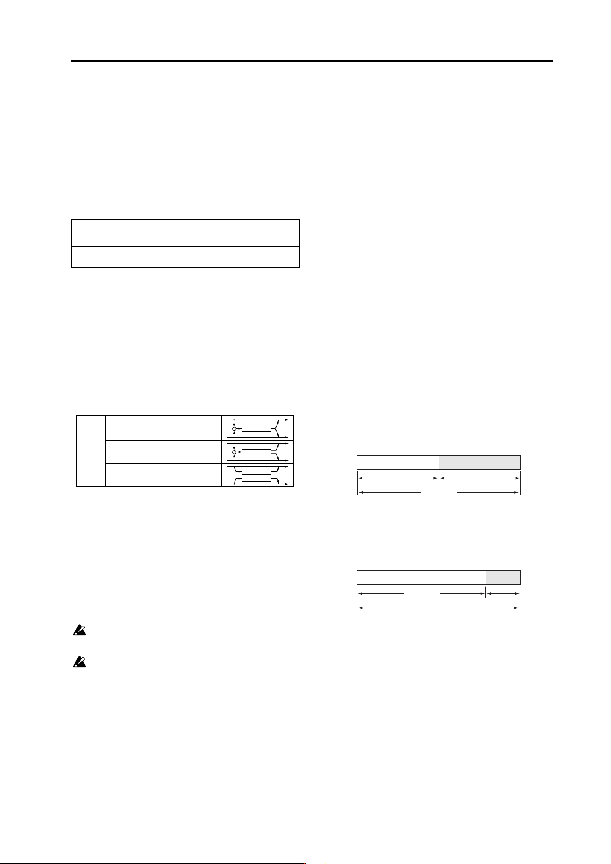
Delay time for the insert effects
Broadly speaking, there are two types of effect for which
you can specify a delay time.
• Delay effects
• Modulation effects such as chorus that internally
use a fixed delay time
If you use such an effect in the two insert effects, the delay time of the effects can be set for a maximum of 1 seconds for each timbre.
Here are some examples.
• Insert effect 1 uses S.Delay (Stereo Delay,) and insert
effect 2 uses S.APnDly (St.Auto Panning Delay.) 500
ms of delay time is assigned to each effect.
Wet
In the block diagram given for each effect in the pages
that follow, the input/output configuration is listed in
the upper left of the diagram.
In order to obtain the best audio quality, use 12. Amp
page “Level,” 7. Mixer page “OSC1 Lvl,” “OSC2 Lvl,”
and “Noise Lvl” to adjust the input level to the insert effect and master effect, and set the “Trim” of each effect
to the maximum level that does not cause clipping. Then
use the “Dry/Wet” and “Output Level” of each effect to
adjust the output level of the effect.
Mono In - Stereo Out
Stereo In - Stereo Out
Some effect types do not have a “Trim” or “Output
Level” parameter.
There is no input level meter that indicates the input level to the effect. If the input level is insufficient, the S/N ratio will be degraded. If the input
level is excessive, clipping may occur.
+
Effect
Effect
Effect
IFX1 IFX2
St. Delay St. Auto Panning Delay
500 msec 500 msec
1.0 sec
• Insert effect 1 uses S.Chorus (St.Chorus,) and insert
effect 2 uses S.Delay (Stereo Delay.) 160 ms of delay
time is assigned to S.Chorus, and 840 ms of delay
time is assigned to St.Delay.
IFX1 IFX2
St. Delay St. Chorus
840 msec
1.0 sec
160 msec
1
Page 4
3
Controlling the effect parameters
On the R3 you can assign one parameter each from insert effects 1 and 2 and the master effect (a total of three
parameters) to knobs [1–[4] and control these parameters while you perform.
Before you assign a parameter to a knob, you must first
select one parameter from each effect and specify this
parameter as the “Fx Knob” in the effect parameter settings (
☞
R3 owner’s manual p.49). After you’ve made
this setting, you can use the Shift function Knob Assign
to select IFx1Knob or IFx2Knob etc., and use the knob to
control the parameter that you assigned in “Fx Knob”
(
☞
R3 owner’s manual p.80).
Synchronizing the LFO 1/2 rate or the delay time of the delay effect to the arpeggiator tempo
You can synchronize the LFO 1/2 rate or the delay time
of the delay effect to the arpeggiator tempo. (When
“BPM SYNC”=ON)
Example 1. LFO1
16. LFO1 page “BPM Sync” (knob [3]): ON
16. LFO1 page LFO1 “SyncNote” (knob [4]): 1/4
In this case, one LFO cycle will occupy the same time as
one quarter note.
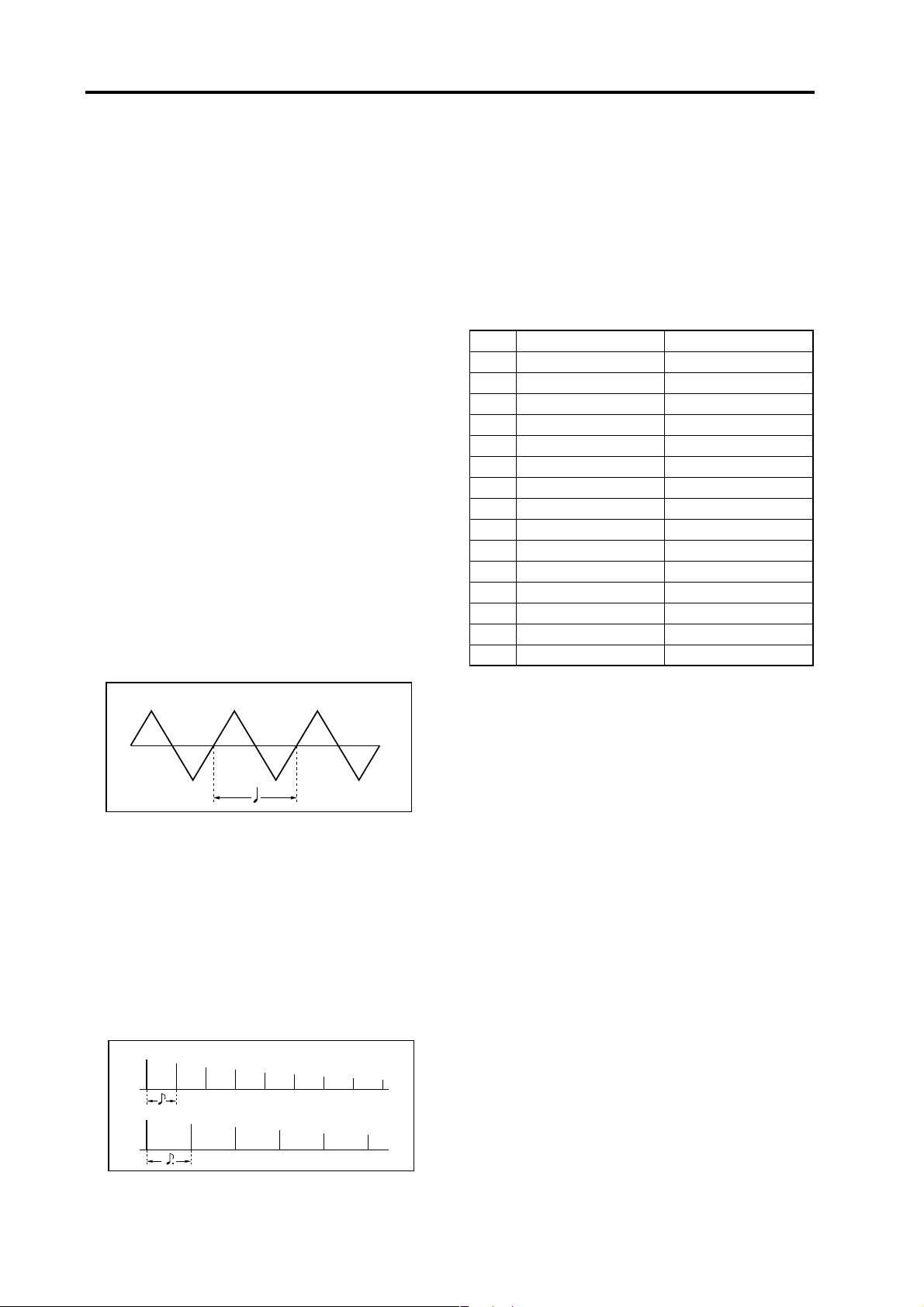
How “SYNC NOTE” and “RESOLUTION” settings correspond
to note values
The following table shows how LFO or delay effect
“SyncNote” settings and 33. Arpeg-B page “Resolutn”
settings correspond to note values.
The parameters will function according to the tempo
specified by [TEMPO] knob and the note value corresponding to its setting.
Note LFO, Delay: “SyncNote” Arpeggiator: “Resolutn”
1/64
1/32 1/32
1/24 1/24
1/16 1/16
3 1/12 1/12
1/8 1/8
3 1/6 1/6
3/16
1/4 1/4
3 1/3
3/8
1/2 1/2
3 2/3
3/4
1/1 1/1
Triangle
Example 2. Delay time
29. Ins FX1 page “Type” (knob [1]): S.Delay
29. Ins FX1 page “Parameter” (knob [3]): BPM Sync,
“Vaue” (knob [4]): On
29. Ins FX1 page “Parameter” (knob [3]): L Delay,
“Vaue” (knob [4]): 1/8
29. Ins FX1 page “Parameter” (knob [3]): R Delay,
“Vaue” (knob [4]):1/8
In this case, the delay time will be set to a time interval
of an eighth note, and will alternate between left and
right channels.
Dry Wet
Lch
Dry Wet
Rch
2
Page 5
Effect parameters
Effect parameters
•
[parameter name]
only MFX
This parameter will be
:
displayed and can be set only when the effect is
used by a master effect.
•
[parameter name]
only IFX
:
This parameter will be
displayed and can be set only when the effect is
used by an insert effect.
[effect name]
•
double size
:
This effect can be selected
only for insert effect 1. If you select this type of
effect, you can’t use insert effect 2.
•
[parameter name]
: This indicates a parameter
you can select for “Fx Knob.” You can assign the
parameter to a front panel knob and edit it while
you perform.
• Common parameters:
Dry/Wet [Dry, 99:1…1:99, Wet]
Fx Knob [available selections depend on the type of
effect]: Choose the effect parameter that you want to
assign to a front panel knob.
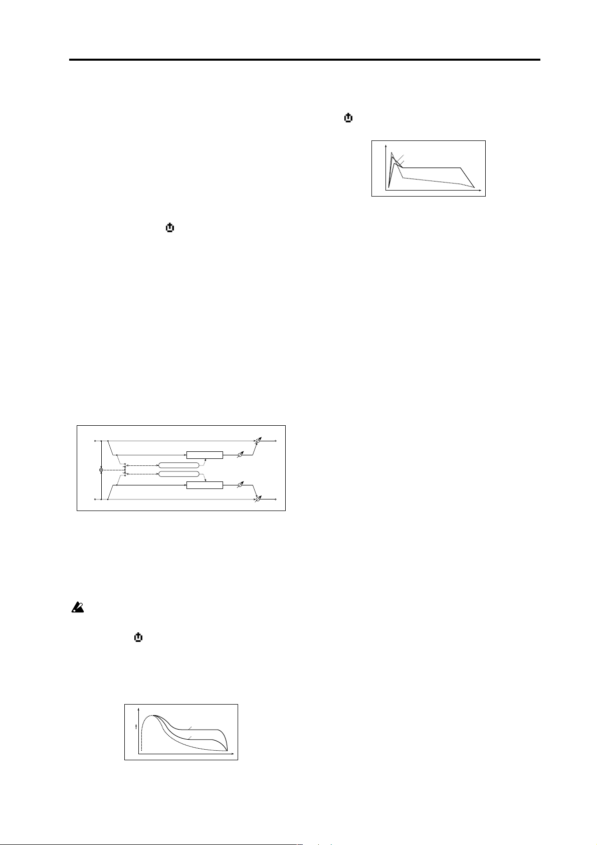
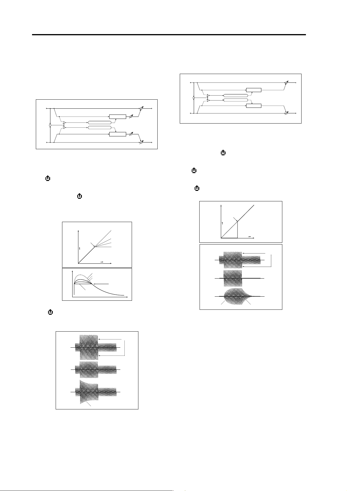
1. S.Comp
(Stereo Compressor)
This effect compresses the input signal to regulate the
level and give a “punchy” effect. This is useful when applied to sounds that have a strong attack.
If using this for the master effect, you can link the left
and right channels or make them operate independently.
Attack [000.1…500.0ms]
Sets the attack level.
Level
Attack=80
Attack=20
Dry
Compressor - Attack
Wet
Time
OutLevel (Output Level) [000…127]
This parameter controls the output level.
Stereo In - Stereo Out
Left
Envelope Select (IFX: LR Mix)
Right
Env Sel (Envelope Select)
Envelope - Control
Envelope - Control
only MFX
Compressor
Compressor
[LR Mix, LR Indv.]
Dry / Wet
Output Level
Output Level
Dry / Wet
When L/R Mix is selected for this parameter, the left
and right channels are linked to control the Limiter using the mixed signal.
With L/R individually, the left and right channels control the Limiter individually.
When using this effect type for an insert effect, this
parameter is fixed at LR Mix.
Sens (Sensitivity) [001…127]
The “Sens” parameter sets the sensitivity of the compressor. If this parameter is set to a higher value, lower
level sounds will be boosted. With a higher Sensitivity,
the overall volume level is higher. To adjust the final
volume level, use the “Output Level” parameter.
Level
Louder
Wet
Dry
Compressor - Sensitivity
Sensitivity=100
Sensitivity=40
Time
3
Page 6
Effect guide
2. S.Limit
(Stereo Limiter)
The Limiter regulates the input signal level. It is similar
to the Compressor, except that the Limiter compresses
only signals that exceed the specified level to lower unnecessary peak signals. If using this for the master effect,
you can link the left and right channels or make them
operate independently.
Stereo In - Stereo Out
Left
+
Envelope Select (IFX: LR Mix)
Right
Env Sel (Envelope Select)
☞
p.3 “1. S.Comp (Stereo Compressor)”
Envelope - Control
Envelope - Control
only MFX
Limiter
Trigger Monitor
Limiter
[LR Mix, LR Indv.]
Gain Adjust
Gain Adjust
Dry / Wet
Dry / Wet
Ratio [1.0:1…50.0:1…Inf:1]
Sets the signal compression ratio.
Threshld (Threshold) [–40…+00dB]
Sets the level above which the compressor is applied.
Compression is applied only when the signal level exceeds the “Threshld” value.
Limiter - Threshold / Ratio
Output Level
Level
Dry
Threshold
Louder
Ratio=Inf : 1
Louder
Ratio=1.0 : 1
Ratio=2.0 : 1
Ratio=4.0 : 1
Ratio=1.0 : 1
Ratio=2.0 : 1
Ratio=4.0 : 1
Ration=Inf : 1
Input Level
Threshold
Time
Attack [000.1…500.0ms]
Sets the attack time. A higher attack time will cause the
compression to be applied more slowly.
Limiter - Attack
Threshold
Dry
3. S.Gate
(Stereo Gate)
This effect mutes the input signal if its level is lower than
the specified level.
Stereo In - Stereo Out
Left
+
Envelope Select (IFX: LR Mix)
Right
Env Sel (Envelope Select)
☞
p.3 “1. S.Comp (Stereo Compressor)”
Envelope - Control
Envelope - Control
only MFX
Gate
Gate
[LR Mix, LR Indv.]
Dry / Wet
Dry / Wet
Threshld (Threshold) [000…127]
Sets the level to which the Gate is applied.
Attack [000.1…500.0ms]
Sets the Gate attack time.
Release [0000.3…1500.0ms]
Sets the Gate release time.
Output Level
Dry
Wet
Wet
Attack
Threshold
Louder
Louder
Gate - Threshold
Input Level
Gate - Attack / Release
Release
Threshold
Attack=0.1ms
Release=0.3ms
Attack=500ms
Release=500ms
GainAjst (Gain Adjust) [–Inf…+24dB]
Sets the output gain.
Wet
Wet
Attack
Ratio=Inf : 1
Attack=1
Ratio=Inf : 1
Attack=100
GainAjst (Gain Adjust) [–Inf…+24dB]
Sets the output gain. Adjust the output level using the
“GainAjst” parameter, since compression causes the entire level to be reduced.
Page 7

Effect parameters
4. S.Filter
(Stereo Filter)
This is a stereo filter.
Stereo In - Stereo Out
Left
LFO
Control Source
Right
Filter (Filter Type) [LPF24, LPF18, LPF12, HPF12, BPF12]
Filter
Response
Filter
Dry / Wet
Dry / Wet
Selects the filter type.
☞
R3 owner’s manual p.32 “FiltBal1”
Cutoff [000…127]
Sets the filter cutoff frequency.
☞
R3 owner’s manual p.32 “Cutoff1”
Resonanc (Resonance) [000…127]
Sets the filter resonance amount.
☞
R3 owner’s manual p.32 “Reso1”
Trim [000…127]
Sets the input level.
Mod Src (Modulation Source) [LFO, Ctrl]
Selects the modulation source that will control the cutoff
frequency. If you set this to LFO, the internal LFO will
modulate the cutoff frequency. If you set this to Ctrl, the
control source selected by “Ctrl Src” will control the cutoff frequency.
Mod Int (Modulation Intensity) [–63…+63]
Adjusts the depth of modulation applied by the modulation source (“Mod Src”).
Response (Modulation Response) [000…127]
Adjusts the response of the modulation effect.
A setting of 0 produces slow response.
LFO Sync (LFO BPM Sync) [Off, On]
Specifies whether the internal LFO cycle will synchronize to the tempo set by the [TEMPO] knob or by MIDI
clock.This parameter will be displayed and can be set if
“Mod Int” is LFO.
If this is Off, the LFO will operate at the cycle specified
by “LFO Freq.”
If this is On, the LFO will synchronize to the tempo or
MIDI clock.
In the 42. MIDI page “Clock” setting is Internal,
the LFO will synchronize to the tempo specified
by the [TEMPO] knob. If the setting is External, the
LFO will synchronize to the MIDI clock received
from an external MIDI device.
LFO Freq (LFO Frequency) [0.01…100.0Hz]
Sets the LFO speed. This parameter This parameter will
be displayed and can be set if “Mod Src” is LFO and
“BPM Sync” is Off.
Increasing this value will result in a faster frequency.
If this parameter is assigned to “Fx Knob,” the assignment will change to SyncNote if you turn
“BPM Sync” on. In the same way, setting “Mod
Src” to Ctrl will cancel this (assign it to Off), and
the knob will have no effect.
SyncNote (LFO SyncNote) [8/1…1/64]
Sets the internal LFO frequency as a proportion of the
tempo set by the [TEMPO] knob if “Mod Src” is LFO and
“BPM Sync” is On. The length of the specified value
(note value) relative to the tempo will be one cycle of the
LFO. For example if this is 1/4, one cycle will occupy
one quarter note.
If this parameter is assigned for “Fx Knob,” turning “BPM Sync” On will switch the assignment to
Sync Note. In the same way, setting “Mod Src” to
Ctrl will cancel this (assign it to Off), and the knob
will have no effect.
LFO Wave (LFO Waveform)
[Saw, Square, Triangle, Sine, S&H]
Selects the internal LFO waveform if “Mod Src” is LFO.
Saw
Sin
LFOShape [–63…+63]
Squ
Tri
S/H
Amplitude changes irregularly
(Sample & Hold)
Adjusts the shape of the internal LFO waveform if “Mod
Src” is LFO.
Key Sync (LFO KeySync) [Off, Timbre]
Specifies how the LFO will be reset at note-on if “Mod
Src” is LFO.
With Off, the LFO phase will not be reset when note-on
occurs.
Note on
With Timbre, the first note-on from a condition of no
keys being pressed will reset the LFO to the phase specified by “IniPhase,” and modulation will be applied at
that phase even if subsequent note-ons occur.
Note on Note on
Note all off
IniPhase (LFO Init Phase) [000…180°]
Specifies the starting position of the waveform if “Key
Sync” is Timbre.
5
Page 8
Effect guide
With a setting of 0°, the waveform will start from its beginning at note-on.
With a setting of 180°, the waveform will start from the
mid-point of its cycle at note-on.
Ctrl Src (Control Source) [Off, Velocity…MIDI3]
Selects the control source if “Mod Src” is Ctrl. The filter
will be controlled by the selected source.
Source Explanation
Off Not used
Velocity Velocity
P.Bend [PITCH] wheel
M.Wheel [MOD] wheel
F.Pedal Foot pedal
F.Sw Foot switch
Damper Damper pedal
MIDI1 Source specified by “MIDI1” in 45. PatchSrc page
MIDI2 Source specified by “MIDI2” in 45. PatchSrc page
MIDI3 Source specified by “MIDI3” in 45. PatchSrc page
5. S.Wah (Stereo Wah)
This stereo wah effect allows you to create sounds from
vintage wah pedal simulation to auto-wah simulation,
and much broader range settings.
Stereo In - Stereo Out
Left
Mod Src
Wah
Response
Wah
Right
Envelope Sens
+
Envelope Shape
Control Source
LFO
Auto
Ctrl
LFO
Wah Type [Y-CRY, RM-A, RM-B, J-CRY, VOX, M-VOX]
Selects the wah type.
If “Mod Src” is Auto or Ctrl (other than PitchBend), settings of “Wah Freq”=0, “Resonanc (Resonance)”=0, and
“Mod Int”=+63 will produce the response of a modeled
wah.
If “Mod Src” is LFO or Ctrl (PitchBend), settings of
“Wah Freq”=32, “Resonanc (Resonance)”=0, and “Mod
Int”=+45 will produce the response of a modeled wah.
Wah Freq (Frequency) [–63…+63]
Sets the wah center frequency.
Dry / Wet
Dry / Wet
Resonanc (Resonance) [–63…+63]
Sets the resonance amount.
Mod Src (Modulation Source) [Auto, LFO, Ctrl]
Selects the source that will control the center frequency
of the wah.
When “Mod Src” is set to Auto will select an auto-wah
that sweeps according to envelope changes in the input
signal level. Auto-wah is frequently used for funk guitar
parts and clav sounds.
When “Mod Src” is set to LFO, the effect uses internal
LFO to sweep in cycle.
When “Mod Src” is set to Ctrl, you can control the filter
directly via the modulation source in the same way as a
wah pedal.
Mod Int (Modulation Intensity) [–63…+63]
Adjusts the depth of the modulation produced by the
modulation source (“Mod Src”).
Response (Modulation Response) [000…127]
Adjusts the response of the modulation effect. A setting
of 0 produces the slowest response.
Env Sens (Envelope Sensitivity) [000…127]
When “Mod Src” is set to Auto, sets the sensitivity of
auto-wah. Increase the value if the input signal is too
low to sweep. Reduce the value if the input signal is so
high that the filter is stopped temporarily.
EnvShape (Envelope Shape) [–63…+63]
When “Mod Src” is set to Auto, this parameter determines the sweep curve for auto-wah.
Page 9
Effect parameters
Level
value = 0...+100
value = 0...–100
Envelope Shape
Envelope
Time
BPM Sync (LFO BPM Sync) [Off, On]
Specifies whether the internal LFO cycle will synchronize to the tempo set by the [TEMPO] knob or MIDI
clock if “Mod Src” is LFO.
☞ p.5 “LFO Sync (LFO BPM Sync)”
LFO Freq (LFO Frequency) [0.01…100Hz]
Sets the LFO speed if “Mod Src” is LFO and “BPM Sync”
is Off.
☞ p.5 “LFO Freq (LFO Frequency)”
SyncNote (LFO SyncNote) [8/1…1/64]
Sets the LFO frequency as a proportion of the tempo set
by the [TEMPO] knob if “Mod Src” is LFO and “BPM
Sync” is On.
☞ p.5 “SyncNote (LFO SyncNote)”
LFO Wave (LFO Waveform)
[Saw, Square, Triangle, Sine, S&H]
Selects the LFO waveform if “Mod Src” is LFO.
☞ p.5 “LFO Wave (LFO Waveform)”
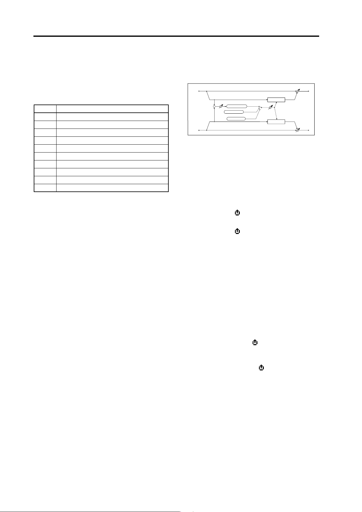
6. S.2BndEQ (Stereo 2Band EQ): IFX S.4BndEQ (Stereo 4Band EQ): MFX
This is a stereo EQ for which the type can be selected independently.
When used in an insert effect, this will be a two-band
stereo EQ.
Insert Effect
Stereo In - Stereo Out
Left
Trim
Trim
Right
Band1
PEQ
LEQ
LEQ
PEQ
Band2
PEQ
HEQ
HEQ
PEQ
When used in the master effect, this will be a four-band
stereo EQ. In this case, the equalizer type of two of the
bands (B2 and B3) is fixed as peaking-type EQ.
Master Effect
Stereo In - Stereo Out
Left
Trim
Trim
Right
Band1
PEQ
LEQ
LEQ
PEQ
Band3
Band2
PEQ PEQ PEQ
PEQ PEQ PEQ
Band4
HEQ
HEQ
Dry / Wet
Dry / Wet
Dry / Wet
Dry / Wet
LFOShape [–63…+63]
Adjusts the shape of the LFO waveform if “Mod Src” is
LFO.
☞ p.5 “LFOShape”
Key Sync (LFO KeySync) [Off, Timbre]
Specifies whether the LFO will be reset at note-on. This
parameter will be displayed and can be set if “Mod Src”
is LFO.
☞ p.5 “Key Sync (LFO KeySync)”
IniPhase (LFO Init Phase) [000…180°]
Specifies the starting position of the waveform. This parameter will be displayed and can be set if “Key Sync” is
Timbre.
☞ p.5 “IniPhase (LFO Init Phase)”
Ctrl Src (Control Source) [Off, Velocity…MIDI3]
Selects the control source used if “Mod Src” is set to Ctrl.
The selected source will control the center frequency of
the wah.
☞ p.6 “Ctrl Src (Control Source)”
Trim [000…127]
Sets the input level of EQ.
B1 Type [Peaking, Shelv Lo]
Selects the EQ type of Band 1.
B2 Type/B4 Type [Peaking, Shelv Hi]
When used in an insert effect, selects the equalizer type
of band 2.
When used in the master effect, selects the equalizer
type of band 4. In this case, band 2 is fixed as a peakingtype EQ.
Band1, Band2 (IFX) / Band4 (MFX) Type
+Gain
–Gain
Band2/4 Type=Shelving High
0dB
Band1 Cutoff
3dB
Band2/4 Type=Peaking
Band1 Type=Shelving Low
Band1 Type=Peaking
3dB
Band2/4 Cutoff
B1 Freq (B1 Frequency) [20Hz…20.0kHz]
Sets the center frequency of Band 1.
B1 Q [00.5…10.0]
Sets the bandwidth of Band 1. This parameter will be
displayed and can be set if “B1 Type” is Peaking.
B1 Gain [–18.0…+18.0dB]
Sets the gain of Band 1.
B2 Freq (B2 Frequency) [20Hz…20.0kHz]
Sets the center frequency of Band 2.
7
Page 10

Effect guide
B2 Q [00.5…10.0]
Sets the bandwidth of Band 2. This parameter will be
displayed and can be set if “B1 Type” is Peaking.
B2 Gain [–18.0…+18.0dB]
Sets the gain of Band 2.
B3 Freq (B3 Frequency)
only MFX
[20Hz…20.0kHz]
Sets the center frequency of Band 3.
only MFX
B3 Q
[00.5…10.0]
Sets the bandwidth of Band 3.
B3 Gain
only MFX
[–18.0…+18.0dB]
Sets the gain of Band 3.
B4 Freq (B4 Frequency)
only MFX
[20Hz…20.0kHz]
Sets the center frequency of Band 4.
only MFX
B4 Q
[00.5…10.0]
Sets the bandwidth of Band 4.
B4 Gain
only MFX
[–18.0…+18.0dB]
Sets the gain of Band 4.
7. Distort (Distortion)
This is a distortion effect with a three band EQ, giving
you a broad range of variations.
Wet: Mono In - Mono Out / Dry: Stereo In - Stereo Out
Left
Right
Pre EQ
+
Distortion
3 Band PEQ
Output Level
Gain [000…127]
Sets the degree of distortion.
Pre Freq (Pre EQ Frequency) [20Hz…20.0kHz]
Sets the center frequency of Pre EQ.
Pre Q (Pre EQ Q) [00.5…10.0]
Sets the bandwidth of Pre EQ.
Pre Gain (Pre EQ Gain) [–18.0…+18.0dB]
Sets the gain of Band PreEQ.
B1 Freq (B1 Frequency) [20Hz…20.0kHz]
Sets the center frequency of Band 1.
Dry / Wet
Dry / Wet
B1 Q [00.5…10.0]
Sets the bandwidth of Band 1.
B1 Gain [–18.0…+18.0dB]
Sets the gain of Band 1.
B2 Freq (B2 Frequency) [20Hz…20.0kHz]
Sets the center frequency of Band 2.
B2 Q [00.5…10.0]
Sets the bandwidth of Band 2.
B2 Gain [–18.0…+18.0dB]
Sets the gain of Band 2.
B3 Freq (B3 Frequency) [20Hz…20.0kHz]
Sets the center frequency of Band 3.
B3 Q [00.5…10.0]
Sets the bandwidth of Band 3.
B3 Gain [–18.0…+18.0dB]
Sets the gain of Band 3.
OutLevel (Output Level) [000…127]
Sets the output level.
Page 11

Effect parameters
8. Cabi Sim (Cabinet Simulator)
This simulates the acoustical character of a guitar amp’s
speaker cabinet.
Wet: Mono In - Mono Out / Dry: Stereo In - Stereo Out
Left
Trim
+
Right
Cabinet Simulator
CabiType (Cabinet Type) [TWD 1X8…US V30]
Selects the type of the cabinet.
TWD 1X8: Open-back cabinet with one 8" speaker
TWD 1X12: Open-back cabinet with one 12" speaker,
typically used for blues.
TWD 4X10: Open-back cabinet with four 10" speakers.
BLK 2X10: Open-back cabinet with two 10" speakers.
BLK 2X12: American open-back cabinet with two 12"
speakers.
AC15: Vox open-back cabinet with one 12" “Blue”
speaker.
AC30: Vox open-back cabinet with two 12" “Blue”
speakers.
AD412: VOX AD412 closed-back cabinet with four 12"
speakers.
UK H30: Closed-back classic cabinet with four 30W 12"
speakers
UK T75: Closed-back cabinet with four 75W 12" speak-
ers.
US V30: Closed-back cabinet with four 30W 12" speak-
ers.
Air [000…127]
Sets the distance between the microphone and the Cabinet. Increasing this value will increase the distance.
Trim [000…127]
Sets the input level.
Dry / Wet
Dry / Wet
9. Tube Sim (Tube PreAmp Simulator): IFX
S.TubSim
This effect simulates a two-stage vacuum tube preamp.
You can make individual settings for two vacuum tubes
connected in series. This lets you create the warm sound
typical of vacuum tubes.
When used in an insert effect, this will be a mono-in/
mono-out effect.
IFX
Wet: Mono In - Mono Out / Dry: Stereo In - Stereo Out
Left
Right
When used in the master effect, this will be a stereo-in/
stereo-out effect.
MFX
Stereo In - Stereo Out
Left
Right
Tu1LoCut (Tube1 Low Cut) [000…127]
Sets the cutoff frequency for the low cut filter of stage 1.
Tu1HiCut (Tube1 High Cut) [000…127]
Sets the cutoff frequency for the high cut filter of stage 1.
Tu1 Gain (Tube1 Gain) [–Inf, –40…+24dB]
Sets the input gain for stage 1.
Tu1 Bias (Tube1 Bias) [000…100%]
Sets the bias voltage for stage 1.
This expresses the effect that changes in vacuum tube
bias have on the distortion of the waveform. Higher settings of this value will produce distortion even at low
gain levels. Since this will also change the overtone
structure, you can use it to control the tonal character.
(Stereo Tube PreAmp Simulator)
Phase
+
Tube Pre Amp1 Tube Pre Amp2
Tube Pre Amp1 Tube Pre Amp2
Tube Pre Amp1 Tube Pre Amp2
+
–
Phase
+
–
Phase
+
–
: MFX
Dry / Wet
Output Level
Dry / Wet
Dry / Wet
Output Level
Output Level
Dry / Wet
Bias
Out
Bias = 100
Bias = 50
Bias = 0
In
Satulation = 50
Tu1 Satu (Tube1 Saturation) [000…100%]
Sets the input/output response for stage 1. With higher
settings of this value, the waveform will change at high
9
Page 12

Effect guide
gain levels, tending to cause distortion. Lower settings
of this value will produce linear response.
Mic/Pre Amp - Saturation
Out
Saturation = 0
Saturation = 50
Saturation = 100
In
Bias = 0
Phase [Normal, Inverted]
Turns phase reversal on/off.
With the Invert setting, the phase of the signal will be inverted between stage 1 and stage 2. Since “Bias” is applied to the inverted signal in stage 2, this will change
the tonal character.
With the Normal setting, the phase will not be reversed.
Tu2LoCut (Tube2 Low Cut) [000…127]
Sets the cutoff frequency for the low cut filter of stage 2.
Tu2HiCut (Tube2 High Cut) [000…127]
Sets the cutoff frequency for the high cut filter of stage 2.
Tu2 Gain (Tube2 Gain) [–Inf, –40…+24dB]
Sets the input gain for stage 2.
Tu2 Bias (Tube2 Bias) [000…100%]
Sets the bias voltage for stage 2.
☞ p.9 “Tu1 Bias (Tube1 Bias)”
Tu2 Satu (Tube2 Saturation) [000…100%]
Sets the input/output response for stage 2.
☞ p.9 “Tu1 Satu (Tube1 Saturation)”
OutLevel (Output Level) [000…127]
Sets the output level.
10. S.Dcmtr (Stereo Decimator)
This effect creates a rough sound like a cheap sampler
by lowering the sampling frequency and data bit length.
You can also simulate noise unique to a sampler (aliasing).
Stereo In - Stereo Out
Left
Right
LFO
Pre LPF
Bit
Sampling Frequency
Pre LPF
Bit
Decimator
Decimator
High Damp Output Level
High Damp Output Level
Pre LPF [Off, On]
Selects whether the harmonic noise caused by a decrease
in sampling frequency is generated or not.
If a sampler with a very low sampling frequency receives very high-pitched sound that could not be heard
during playback, it could generate pitch noise that is unrelated to the original sound. Set “Pre LPF” to On to prevent this noise from being generated.
If you set the “Fs” to about 3kHz and set “Pre LPF” to
Off, you can create a sound like a ring modulator.
HighDamp [000…100%]
Sets the ratio of cut of the high range.
Fs [01.0k…48.0kHz]
Sets the sampling frequency.
Bit [04…24bit]
Sets the data bit length.
If you set a smaller value for the “Bit” parameter, the
sound may be distorted. The volume level may also be
changed. Use “OutLevel” to adjust the level.
OutLevel (Output Level) [000…127]
Sets the output level.
FsModInt (Fs Modulation Intensity) [–63…+63]
Sets the depth of sampling frequency LFO modulation.
Dry / Wet
Dry / Wet
10
LFO Sync (LFO BPM Sync) [Off, On]
Specifies whether the internal LFO cycle will synchronize to the tempo specified by the [TEMPO] knob or
MIDI clock.
☞ p.5 “LFO Sync (LFO BPM Sync)”
LFO Freq (LFO Frequency) [0.01…100.0Hz]
Sets the LFO speed. This parameter will be displayed
and can be set if “Mod Src” is LFO and “BPM Sync” is
Off.
☞ p.5 “LFO Freq (LFO Frequency)”
SyncNote (LFO SyncNote) [8/1…1/64]
Sets the internal LFO frequency as a proportion of the
tempo set by the [TEMPO] knob if “BPM Sync” is On.
☞ p.5 “SyncNote (LFO SyncNote)”
Page 13

Effect parameters
LFO Wave (LFO Waveform)
[Saw, Square, Triangle, Sine, S&H]
Selects the internal LFO waveform.
☞ p.5 “LFO Wave (LFO Waveform)”
LFO Shape [–63…+63]
Adjusts the shape of the LFO waveform.
☞ p.5 “LFOShape”
Key Sync (LFO KeySync) [Off, Timbre]
Specifies whether the LFO will be reset at note-on.
☞ p.5 “Key Sync (LFO KeySync)”
IniPhase (LFO Init Phase) [000…180°]
Specifies the starting position of the waveform if “KeySync” is Timbre.
☞ p.5 “IniPhase (LFO Init Phase)”
11. Reverb
This effect simulates acoustical ambience such as the reverberation of a hall.
MFX Hall, SmoothHall
Wet: Mono In - Stereo Out / Dry: Stereo In - Stereo Out
Left
EQ Trim
LEQ HEQ
+
EQ Trim
Right
MFX Room, BritRoom
Wet: Mono In - Stereo Out / Dry: Stereo In - Stereo Out
Left
EQ Trim
LEQ HEQ
+
EQ Trim
Right
Pre Delay Thru
Pre Delay
Pre Delay
Reverb
ERs
Pre Delay Thru
Reverb
ERs
Type [Hall…BritRoom]
Selects the reverb type. The reverb types that you can select will differ depending on whether this effect is used
in an insert effect or in the master effect.
Hall: Hall-type reverb, producing the reverberation of a
mid to large-size concert or ensemble hall.
SmthHall
only MFX:
Hall-type reverb, producing the reverberation of a larger hall or stadium. The reverberation features a smooth release. Selectable only for the
master effect.
only IFX
Plate
: Plate reverb. Selectable only for an insert
effect.
WetPlate
only MFX
: Plate reverb that produces warm,
dense reverberation. Selectable only for the master effect.
DryPlate
only MFX:
Plate reverb with a dry, light feel. Se-
lectable only for the master effect.
Room: Room-type reverb with a tight feeling, and em-
phasis on the early reflections. By changing the balance
between the early reflections and the reverberation, you
can simulate different types of wall material.
BritRoom
only MFX
: Room-type reverb with a bright feel-
ing, and emphasis on the early reflections (☞Reverb
Room). Selectable only for the master effect.
ER Level
Reverb Level
ER Level
Wet / Dry
Wet / Dry
Dry / Wet
Dry / Wet
Rev Time (Reverb Time)
[Hall or Plate: 00.1…10.0sec, Room: 00.1…03.0sec]
Sets the reverberation time. The selectable range of reverb time will depend on the “Type” setting.
High Damp [000…100%]
Sets the damping amount in the high range.
PreDelay
only MFX
[000…200msec]
Sets the delay time from the dry sound.
PrDlyThr (Pre Delay Thru)
only MFX
[000…127]
Sets the mix ratio of non-delay sound.
11
Page 14

Effect guide
Trim (Pre EQ Trim)
only MFX
[000…127]
Sets the EQ input level.
LoEQGain (Low EQ Gain)
only MFX
[–15.0…+15.0dB]
Sets the gain of Low EQ.
HiEQGain (High EQ Gain)
only MFX
[–15.0…+15.0dB]
Sets the gain of High EQ.
ER Level
only MFX
[000…127]
Sets the time taken from the original sound to the first
early reflection. When used for the master effect, this is
displayed and can be set only if Room or BritRoom is selected.
Rev Level (Reverb Level)
only MFX
[000…127]
Sets the reverberation level. When used for the master
effect, this is displayed and can be set only if Room or
BritRoom is selected.
12. EarlyRef (Early Reflections)
This effect is only the early reflection part of a reverberation sound, and adds presence to the sound. You can
select one of the four decay curves.
Wet: Mono In - Stereo Out / Dry: Stereo In - Stereo Out
Left
EQ Trim
IFX: High Damp
MFX: HEQ
Pre Delay
Early Reflections
Right
+
EQ Trim
IFX: Low Damp
MFX: LEQ
Type [Sharp, Loose, Modulate, Reverse]
Selects the decay curve for the early reflection.
Early Reflections - Type
Sharp
Loose
Modulated
Dry / Wet
Dry / Wet
Reverse
Dry
Pre Delay
ER Time
ER Time [IFX: 010…400msec/MFX: 010…800msec]
Sets the time from the original sound to the first early reflection. The range of this parameter will differ depending on whether the effect is an insert effect or a master
effect.
PreDelay [IFX: 000…100msec/MFX: 000…200msec]
Sets the time taken from the original sound to the first
early reflection. The range of this parameter will differ
depending on whether the effect is an insert effect or a
master effect.
Trim (Pre EQ Trim) [000…127]
Sets the input level of EQ applied to the effect sound.
LoEQGain (Low EQ Gain)
only MFX
[–15.0…+15.0dB]
Sets the gain of Low EQ.
HiEQGain (High EQ Gain)
only MFX
[–15.0…+15.0dB]
Sets the gain of High EQ.
HighDamp
only IFX
[000…100%]
Sets the damping amount in the high range.
Low Damp
only IFX
[000…100%]
Sets the damping amount in the low range.
12
Page 15

Effect parameters
13. LCR Dly (L/C/R Delay)
This multitap delay outputs three Tap signals to the left,
center, and right respectively. You can also adjust the
left and right spread of the delay sound.
Wet: Mono In - Stereo Out / Dry: Stereo In -Stereo Out
Left
L Delay
C Delay
R Delay
Feedback
Level
Level
Level
Spread
Right
+
Trim
Trim
High Damp
Low Damp
BPM Sync (Delay Time BPM Sync) [Off, On]
Specifies whether the delay time will be synchronized.
If this is On, the delay time will synchronize to the tempo or MIDI clock.
TimRatio (Time Ratio)
[BPM Sync Off: 000.5…400.0% (OVER)
BPM Sync On: 012.5…400.0% (OVER)]
Sets each delay time as a proportion relative to the “L
Delay,” “C Delay,” and “R Delay” values. The available
range will depend on whether “BPM Sync” is On or Off.
For example if “TimRatio” is 50%, “L Delay” is 500
msec, “C Delay” is 700 msec, and “R Delay” is 1000
msec, the delay times will be 250 msec, 350 msec, and
500 msec respectively.
Dry / Wet
Dry / Wet
Spread [000…127]
Sets the width of the stereo image of the effect sound.
The stereo image is widest with a value of 127, and the
effect sound of both channels is output from the center
with a value of 0.
If you use this effect and a delay or chorus effect as
the two insert effects, the delay times will be limited. If the delay times in conjunction with the “TimRatio” setting exceed the limit, “TimRatio” will
indicate OVER.
L Delay, C Delay, R Delay (L, C, R Delay Time)
[BPM Sync Off IFX: 0000…1000msec
BPM Sync Off MFX: 0000…1400msec
BPM Sync On: 1/64… 1/1]
These set the L, C, and R delay times. The delay time is
determined by these settings and the “TimRatio” value.
If “BPM Sync” is Off, these delay times are set in msec
units. The range of this parameter will differ depending
on whether the effect is an insert effect or a master effect.
If “BPM Sync” is On, these delay times are set as a timing resolution relative to the tempo specified by the
[TEMPO] knob or MIDI clock.
L Level, C Level, R Level (L, C, R Delay Level) [000…127]
These adjust the output level of the L, C, and R delays.
C Fback (C Feedback) [000…127]
Sets the feedback amount of TapC.
High Damp [000…100%]
Sets the damping amount in the high range.
Low Damp [000…100%]
Sets the damping amount in the low range.
Trim [000…127]
Sets the input level.
13
Page 16

Effect guide
14. S.Delay (Stereo Delay)
This is a stereo delay, and can by used as a cross-feedback delay effect in which the delay sounds cross over
between the left and right by changing the feedback
routing.
Stereo In - Stereo Out
Left
Trim
Stereo/Cross
Trim
Right
Delay
Delay
High Damp Low Damp
Feedback
Low Damp
High Damp
Stereo/Cross
Type [Stereo, Cross]
Selects the delay type. With the Stereo setting, this will
be a conventional stereo delay. With the Cross setting,
this will be a cross-feedback delay in which the delay
sound bounces between left and right.
BPM Sync (Delay Time BPM Sync) [Off, On]
Specifies whether the delay tempo will be synchronized.
☞ p.13 LCR Delay “BPM Sync (Delay Time BPM Sync)”
TimRatio (Time Ratio)
[BPM Sync Off: 000.5…400.0% (OVER)
BPM Sync On: 012.5…400.0% (OVER)]
☞ p.13 LCR Delay “TimRatio (Time Ratio)”
L Delay, R Delay (L, R Delay Time)
[BPM Sync Off IFX: 000…500msec
BPM Sync Off MFX: 000…700msec
BPM Sync Off: 1/64…1/1]
These set the left and right channel delay times. The delay time is determined by these settings and the “TimRatio” value.
If “BPM Sync” is Off, these delay times are set in msec
units. The range of this parameter will differ depending
on whether the effect is an insert effect or a master effect.
If “BPM Sync” is On, these delay times are set as a timing resolution relative to the tempo specified by the
[TEMPO] knob or MIDI clock.
Feedback [000…127]
Sets the amount of feedback for the left and right channels.
HighDamp [000…100%]
Sets the damping amount in the high range.
Low Damp [000…100%]
Sets the damping amount in the low range.
Trim [000…127]
Sets the input level.
Spread [000…127]
Sets the width of the stereo image of the effect sound.
☞ p.13 LCR Delay “Spread”
Dry / Wet
Spread
Dry / Wet
15. AtPanDly (Auto Panning Delay)
This stereo delay effect pans the delay sound left and
right using the LFO.
Wet: Mono In - Stereo Out / Dry: Stereo In -Stereo Out
Left
Trim
Right
Trim
Delay
High Damp Low Damp
Feedback
LFO Shape
+
LFO
Pan
LFO Spread
BPM Sync (Delay Time BPM Sync) [Off, On]
Specifies whether the delay tempo will be synchronized.
☞ p.13 LCR Delay “BPM Sync (Delay Time BPM Sync)”
TimRatio (Time Ratio)
[BPM Sync Off: 000.5…400.0% (OVER)
BPM Sync On: 012.5…400.0% (OVER)]
☞ p.13 LCR Delay “TimRatio (Time Ratio)”
L Delay, R Delay (L, R Delay Time)
[BPM Sync Off IFX: 0000…1000msec
BPM Sync Off MFX: 0000…1400mse
BPM Sync On: 1/64… 1/1]
These set the left and right channel delay times. The delay time is determined by these settings and the “TimRatio” value.
If “BPM Sync” is Off, these delay times are set in msec
units. The range of this parameter will differ depending
on whether the effect is an insert effect or a master effect.
If “BPM Sync” is On, these delay times are set as a timing resolution relative to the tempo specified by the
[TEMPO] knob or MIDI clock.
Feedback [000…127]
Sets the feedback amount for the left channel.
ModDepth (Modulation Depth) [000…127]
Sets the depth of modulation.
LFO Sync (LFO BPM Sync) [Off, On]
Specifies whether the internal LFO cycle will be synchronized with the tempo specified by the [TEMPO]
knob or MIDI clock.
☞ p.5 “LFO Sync (LFO BPM Sync)”
LFO Freq (LFO Frequency) [0.01…100.0Hz]
Sets the internal LFO frequency if “BPM Sync” is Off.
☞ p.5 “LFO Freq (LFO Frequency)”
SyncNote (LFO SyncNote) [8/1…1/64]
Sets the internal LFO frequency as a proportion of the
tempo set by the [TEMPO] knob if “BPM Sync” is On.
☞ p.5 “SyncNote (LFO SyncNote)”
LFO Wave (LFO Waveform)
[Saw, Square, Triangle, Sine, S&H]
Selects the internal LFO waveform.
☞ p.5 “LFO Wave (LFO Waveform)”
Depth
Dry / Wet
Dry / Wet
14
LFO Shape [–63…+63]
☞ p.5 “LFOShape”
Page 17

Effect parameters
Key Sync (LFO Key Sync) [Off, Timbre]
Specifies whether the LFO will be reset by note-on.
☞ p.5 “Key Sync (LFO KeySync)”
IniPhase (LFO Init Phase) [000…180°]
Sets the starting location of the waveform if “Key Sync”
is Timbre.
☞ p.5 “IniPhase (LFO Init Phase)”
High Damp [000…100%]
Sets the damping amount in the high range.
Low Damp [000…100%]
Sets the damping amount in the low range.
Trim [000…127]
Sets the input level.
16. S.APnDly (Stereo Auto Panning Delay)
This is a stereo delay that uses an LFO to pan the delay
sound between left and right.
Stereo In - Stereo Out
Left
Right
Trim
Trim
LFO
Delay
Delay
LFO Shape
High Damp Low Damp
Feedback
High Damp
Low Damp
Pan
Pan
LFO Spread
BPM Sync (DelayTime BPM Sync) [Off, On]
Specifies whether the delay tempo will be synchronized.
☞ p.13 LCR Delay “BPM Sync (Delay Time BPM Sync)”
TimRatio (Time Ratio)
[BPM Sync Off: 000.5…400.0% (OVER)
BPM Sync On: 012.5…400.0% (OVER)]
☞ p.13 LCR Delay “TimRatio (Time Ratio)”
L Delay, R Delay (L, R Delay Time)
[BPM Sync Off IFX: 000…500msec
BPM Sync Off MFX: 000…700msec
BPM Sync On: 1/64…1/1]
These set the left and right channel delay times.
☞ p.14 StDelay “L Delay, R Delay (L, R Delay Time)”
Dry / Wet
Depth
Dry / Wet
Feedback [000…127]
Sets the feedback amount for the left channel.
☞ p.14 StDelay “Feedback”
ModDepth (Modulation Depth) [000…127]
Sets the depth of modulation.
LFO Sync (LFO BPM Sync) [Off, On]
Specifies whether the internal LFO cycle will be synchronized with the tempo specified by the [TEMPO]
knob or MIDI clock.
☞ p.5 “LFO Sync (LFO BPM Sync)”
LFO Freq (LFO Frequency) [0.01…100.0Hz]
Sets the LFO speed if “BPM Sync” is Off.
☞ p.5 “LFO Freq (LFO Frequency)”
SyncNote (LFO SyncNote) [8/1…1/64]
Sets the LFO frequency as a proportion of the tempo set
by the [TEMPO] knob if “BPM Sync” is On.
☞ p.5 “SyncNote (LFO SyncNote)”
LFO Wave (LFO Waveform)
[Saw, Square, Triangle, Sine, S&H]
Selects the internal LFO waveform.
☞ p.5 “LFO Wave (LFO Waveform)”
LFOShape (LFO Shape) [–63…+63]
Adjusts the shape of the internal LFO waveform.
☞ p.5 “LFOShape”
Key Sync (LFO Key Sync) [Off, Timbre]
Specifies whether the LFO will be reset by note-on.
☞ p.5 “Key Sync (LFO KeySync)”
15
Page 18

Effect guide
IniPhase (LFO Init Phase) [000…180°]
Sets the starting location of the waveform if “KeySync” is
Timbre.
☞ p.5 “IniPhase (LFO Init Phase)”
LFOSpred (LFO Spread) [–180…+180°]
Sets the phase difference between the left and right
channels.
HighDamp [000…100%]
Sets the damping amount in the high range.
Low Damp [000…100%]
Sets the damping amount in the low range.
Trim [000…127]
Sets the input level.
17. ModDelay (Modulation Delay)
This stereo delay uses an LFO to sweep the delay time.
The pitch also varies. You will obtain a delay sound with
swell and shimmering. You can also control the delay
time using a modulation source.
Wet: Mono In - Stereo Out / Dry: Stereo In -Stereo Out
Left
Feedback
+
Right
LFO
Delay
LFO Spread
BPM Sync (DelayTime BPM Sync) [Off, On]
Specifies whether the delay tempo will be synchronized.
☞ p.13 LCR Delay “BPM Sync (Delay Time BPM Sync)”
TimRatio (Time Ratio)
[BPM Sync Off: 000.5…400.0% (OVER)
BPM Sync On: 012.5…400.0% (OVER)]
☞ p.13 LCR Delay “TimRatio (Time Ratio)”
L Delay, R Delay (L, R Delay Time)
[BPM Sync Off IFX: 000…980msec
BPM Sync Off MFX: 0000…1380msec
BPM Sync On 1/64…1/1]
☞ p.14 StDelay “L Delay, R Delay (L, R Delay Time)”
Dry / Wet
Dry / Wet
Feedback [000…127]
Sets the feedback amount for the left channel.
ModDepth (Modulation Depth) [000…127]
Sets the depth of LFO modulation.
LFO Freq (LFO Frequency) [0.01…100.0Hz]
Sets the LFO speed. Increasing this value will result in a
faster frequency.
LFOSpred (LFO Spread) [–180…+180°]
Sets the phase difference between the left and right
channels.
16
Page 19

Effect parameters
18. S.ModDly (Stereo Modulation Delay)
This is a stereo modulation delay.
Stereo In - Stereo Out
Left
Delay
Feedback
Delay
Right
LFO Spread
LFO
BPM Sync (DelayTime BPM Sync) [Off, On]
Specifies whether the delay tempo will be synchronized.
☞ p.13 LCR Delay “BPM Sync (Delay Time BPM Sync)”
TimRatio (Time Ratio)
[BPM Sync Off: 000.5…400.0% (OVER)
BPM Sync On: 012.5…400.0% (OVER)]
☞ p.13 LCR Delay “TimRatio (Time Ratio)”
L Delay, R Delay (L, R Delay Time)
[BPM Sync Off IFX: 000…480msec
BPM Sync Off MFX: 000…680msec
BPM Sync On 1/64…1/1]
☞ p.14 StDelay “L Delay, R Delay (L, R Delay Time)”
Feedback [000…127]
☞ p.14 StDelay “Feedback”
ModDepth (Modulation Depth) [000…127]
Sets the depth of internal LFO modulation.
LFO Freq (LFO Frequency) [0.01…100.0Hz]
Sets the internal LFO speed. Increasing this value will
result in a faster frequency.
LFO Spred (LFO Spread) [–180…+180°]
Sets the phase difference between the left and right
channels.
Dry / Wet
Dry / Wet
19. TapeEcho
This effect simulates a tape echo unit. The distortion and
tonal change typical of magnetic tape are also reproduced.
Wet: Mono In - Stereo Out / Dry: Stereo In - Stereo Out
Left
Right
Feedback
Pre Tone
Tape
Saturation
High / Low Damp
Wah Flutter
+
Trim
Tape1 Level
Delay
Tap2 Level
BPM Sync (DelayTime BPM Sync) [Off, On]
Specifies whether the delay tempo will be synchronized.
☞ p.13 LCR Delay “BPM Sync (Delay Time BPM Sync)”
TimRatio (Time Ratio)
[BPM Sync Off: 000.5…400.0% (OVER)
BPM Sync On: 012.5…400.0% (OVER)]
☞ p.13 LCR Delay “TimRatio (Time Ratio)”
Tap1Delay, Tap2 Delay(Tap1, Tap2 Delay Time)
[BPM Sync Off IFX: 000…980msec
BPM Sync Off MFX: 0000…1380msec,
BPM Sync On: 1/64… 1/1]
Sets the delay times for Tap1 and Tap2.
☞ p.13 LCR Delay “L Delay, C Delay, R Delay (L, C, R
Delay Time)”
Tap1Lvl, Tap2 Lvl (Tap1 Level, Tap2 Level) [000…127]
Sets the Tap1 output level and Tap2 output level.
Feedback [000…127]
Sets the Tap1 feedback amount.
HighDamp [000…100%]
Sets the damping amount in the high range.
Low Damp [000…100%]
Sets the damping amount in the low range.
Dry / Wet
Spread
Dry / Wet
Trim [000…127]
Sets the input level.
Saturatn (Saturation) [000…127]
Sets the distortion amount.
Waw Freq (Wah Flutter Frequency) [0.01…100.0Hz]
Sets the frequency at which pitch variation will occur in
Hz stepsl.
WawDepth (Wah Flutter Depth) [000…127]
Sets the depth of pitch variation.
Pre Tone [000…127]
Sets the tone of the input.
Spread [000…127]
Sets the width of the stereo image of the effect sound.
☞ p.13 LCR Delay “Spread”
17
Page 20

Effect guide
20. S.Chorus (Stereo Chorus)
This effect adds thickness and warmth to the sound by
modulating the delay time of the input signal. You can
add spread to the sound by offsetting the phase of the
left and right LFOs from each other.
Stereo In - Stereo Out
Left
Right
Trim
Trim
LFO
LEQ
LEQ
HEQ
HEQ
Chorus
Chorus
LFO Spread
ModDepth (Modulation Depth) [000…127]
Sets the depth of LFO modulation.
LFO Freq (LFO Frequency) [0.01…100.0Hz]
Sets the internal LFO speed. Increasing this value will
result in a faster frequency.
LFOSpred (LFO Spread) [–180…+180°]
Sets the LFO phase difference between the left and right.
PreDly L, PreDly R (Pre Delay L, R) [00.0…50.0msec]
Sets the delay times for the left and right channels.
Dry / Wet
Dry / Wet
21. Ensemble
This effect produces a deep and spacious ensemble
sound.
Wet: Mono In - Stereo Out / Dry: Stereo In - Stereo Out
Left
+
Right
Ensemble
LFO
ModDepth (Modulation Depth) [000…127]]
Sets the depth of LFO modulation.
Speed [001…127]
Sets the LFO speed.
Dry / Wet
Dry / Wet
Trim [000…127]
Sets the input level.
LoEQGain (Low EQ Gain) [–15.0…+15.0dB]
Sets the gain of Low EQ.
HiEQGain (High EQ Gain) [–15.0…+15.0dB]
Sets the gain of High EQ.
18
Page 21

Effect parameters
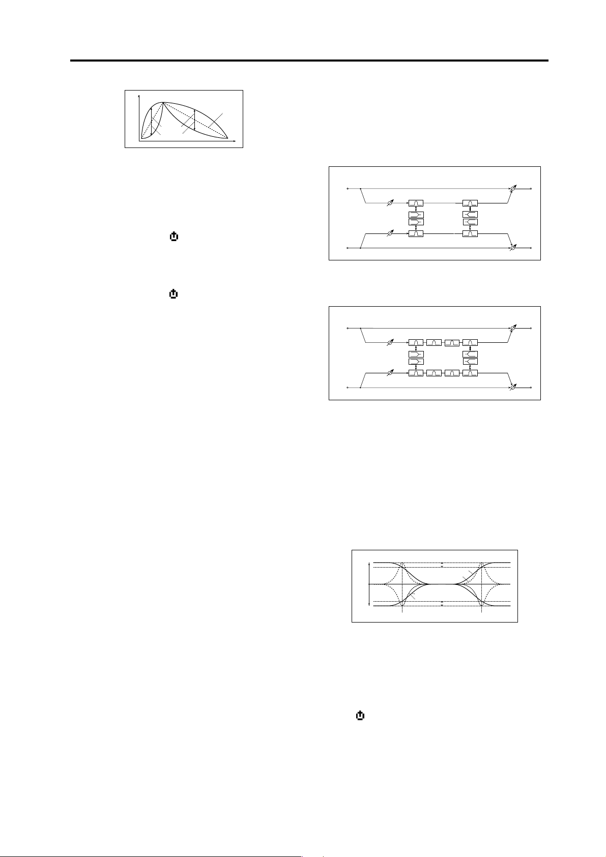
22. S.Flangr (Stereo Flanger/Comb Filter)
This effect gives a significant swell and movement of
pitch to the sound. It is more effective when applied to a
sound with a lot of harmonics. This is a stereo flanger.
You can add spread to the sound by offsetting the phase
of the left and right LFOs from each other. This effect can
also be used as a comb filter.
Stereo In - Stereo Out
Left
Flanger
Feedback
Flanger
Right
LFO
LFO Shape
LFO Spread
Type [Flanger, Comb]
Switches the effect between flanger and comb filter.
Delay [00.0…30.0msec]
Sets the delay time in millisecond steps when “Type” is
set to Flanger.
If this parameter is assigned to “Fx Knob,” setting
“Type” to Comb will switch the assignment to
Cutoff.
Dry / Wet
High Damp (Type: Flanger)
Dry / Wet
LFOShape (LFO Shape) [–63…+63]
Adjusts the shape of the internal LFO waveform.
☞ p.5 “LFOShape”
Key Sync (LFO KeySync) [Off, Timbre]
Specifies whether the LFO will be reset by note-on.
☞ p.5 “Key Sync (LFO KeySync)”
IniPhase (LFO Init Phase) [000…180°]
Sets the starting location of the waveform if “Key Sync”
is Timbre.
☞ p.5 “IniPhase (LFO Init Phase)”
LFO Spred (LFO Spread) [–180…180°]
Sets the LFO phase difference between the left and right
channels.
HighDamp [000…100%]
Sets the feedback damping amount in the high range if
the “Type” is Flanger.
Cutoff (Cutoff Frequency) [000…127]
When “Type” is set to Comb, this sets the cutoff frequency of the comb filter.
ModDepth (Modulation Depth) [000…127]
Sets the depth of LFO modulation.
Feedback [000…127]
Sets the amount of feedback for the left and right channels.
Phase [+, –]
When “Type” is set to Flanger, this switches the phase of
the output and feedback.
LFO Sync (LFO BPM Sync) [Off, On]
Specifies whether the internal LFO cycle will be synchronized with the tempo specified by the [TEMPO]
knob or MIDI clock.
☞ p.5 “LFO Sync (LFO BPM Sync)”
LFO Freq (LFO Frequency) [0.01…100.0Hz]
Sets the LFO speed if “BPM Sync” is Off.“
☞ p.5 “LFO Freq (LFO Frequency)”
SyncNote (LFO SyncNote) [8/1…1/64]
Sets the LFO frequency as a proportion of the tempo set
by the [TEMPO] knob. This parameter will be displayed
and can be set if “BPM Sync” is On.“
☞ p.5 “SyncNote (LFO SyncNote)”
LFO Wave (LFO Waveform)
[Saw, Square, Triangle, Sine, S&H]
Selects the internal LFO waveform.
☞ p.5 “LFO Wave (LFO Waveform)”
19
Page 22

Effect guide
23. S.Phaser (Stereo Phaser)
This effect creates a swell by shifting the phase. It is very
effective on electric piano sounds. You can add spread
to the sound by offsetting the phase of the left and right
LFOs from each other.
Stereo In - Stereo Out
Left
Phaser
Resonance
High Damp
Right
LFO
LFO Shape
Phaser
LFO Spread
Type [Blue, U-VB]
Selects the phaser type.
Manual [000…127]
Sets the frequency to which the effect is applied.
ModDepth (Modulation Depth) [000…127]
Sets the depth of the internal LFO modulation.
Resonanc (Resonance) [000…127]
Sets the resonance amount.
Dry / Wet
Dry / Wet
LFO Spred (LFO Spread) [–180…+180°]
Sets the LFO phase difference between the left and right
channels.
HighDamp [000…100%]
Sets the feedback damping amount in the high range.
Phase [+, –]
Switches the phase of the output and feedback.
LFO Sync (LFO BPM Sync) [Off, On]
Specifies whether the internal LFO cycle will be synchronized with the tempo specified by the [TEMPO]
knob or MIDI clock.
☞ p.5 “LFO Sync (LFO BPM Sync)”
LFO Freq (LFO Frequency) [0.01…100.0Hz]
Sets the LFO speed if “BPM Sync” is Off.
☞ p.5 “LFO Freq (LFO Frequency)”
SyncNote (LFO SyncNote) [8/1…1/64]
Sets the LFO frequency as a proportion of the tempo set
by the [TEMPO] knob if “BPM Sync” is On.
☞ p.5 “SyncNote (LFO SyncNote)”
LFO Wave (LFO Waveform)
[Saw, Square, Triangle, Sine, S&H]
Selects the internal LFO waveform.
☞ p.5 “LFO Wave (LFO Waveform)”
LFO Shape [–63…+63]
Adjusts the shape of the internal LFO waveform.
☞ p.5 “LFOShape”
Key Sync (LFO KeySync) [Off, Timbre]
Specifies whether the LFO will be reset by note-on.
☞ p.5 “Key Sync (LFO KeySync)”
IniPhase (LFO Init Phase) [000…180°]
Sets the starting location of the waveform if “Key Sync” is
Timbre.
☞ p.5 “IniPhase (LFO Init Phase)”
0
Page 23

Effect parameters
24. S.Tremol (Stereo Tremolo)
This effect modulates the volume level of the input signal. The effect is stereo, and offsetting the LFO of the left
and right phases from each other produces a tremolo effect between left and right.
Stereo In - Stereo Out
Left
Tremolo
Tremolo
Right
LFO
LFO Shape
LFO Spread
ModDepth (Modulation Depth) [000…127]
Sets the depth of internal LFO modulation.
LFO Sync (LFO BPM Sync) [Off, On]
Specifies whether the LFO cycle will be synchronized with
the tempo specified by the [TEMPO] knob or MIDI clock.
☞ p.5 “LFO Sync (LFO BPM Sync)”
LFO Freq (LFO Frequency) [0.01…100.0Hz]
Sets the internal LFO speed if “BPM Sync” is Off.
☞ p.5 “LFO Freq (LFO Frequency)”
SyncNote (LFO SyncNote) [8/1…1/64]
Sets the internal LFO frequency as a proportion of the
tempo set by the [TEMPO] knob if “BPM Sync” is On.
☞ p.5 “SyncNote (LFO SyncNote)”
LFO Wave (LFO Waveform)
[Saw, Square, Triangle, Sine, S&H]
Selects the internal LFO waveform.
☞ p.5 “LFO Wave (LFO Waveform)”
LFOShape (LFO Shape) [–63…+63]
Adjusts the shape of the internal LFO waveform.
☞ p.5 “LFOShape”
Key Sync (LFO KeySync) [Off, Timbre]
Specifies whether the LFO will be reset by note-on.
☞ p.5 “Key Sync (LFO KeySync)”
IniPhase (LFO Init Phase) [000…180°]
Sets the starting location of the waveform if “Key Sync”
is Timbre.
☞ p.5 “IniPhase (LFO Init Phase)”
LFOSpred (LFO Spread) [–180…+180°]
Sets the internal LFO phase difference between the left
and right channels.
Dry / Wet
Dry / Wet
25. S.RingMd (Stereo Ring Modulator)
This effect creates a metallic sound by applying the oscillators to the input signal. Use the LFO or Dynamic
Modulation to modulate the oscillator to create a radical
modulation. Matching the oscillator frequency with a
note number will produce a ring modulation effect in
specific key ranges.
Stereo In - Stereo Out
Left
Right
Fixed Frequency
Note No.
Note Offset, Fine
LFO
Pre LPF
Pre LPF
Fixed
OSC Mode
Note (Key Follow)
Oscillator
Ring Modulator
Ring Modulator
Pitch
OSC Mode (Oscillator Mode) [Fixed, Note]
Switching between specifying the oscillator frequency
and using a note number.
If this is set to Note, the oscillator frequency will track
the note of the input signal.
FixedFrq (Fixed Frequency) [0…12.0kHz]
This parameter sets the oscillator frequency when “OSC
Mode” is set to Fixed.
If this parameter is assigned to “Fx Knob,” setting
“OSC Mode” to Note will switch the assignment
to NoteOfst.
NoteOfst (Note Offset) [–48…+48]
Sets the pitch difference from the original note in semitone steps when “OSC Mode” is set to Note.
NoteFine (Note Fine) [–100…+100cent]
Sets the pitch difference from the original note in cent
steps when “OSC Mode” is set to Note.
By setting “NoteOfst” and “NoteFine” so that the
oscillator frequency will track the note that is input, you can produce a ring modulator effect with
a correct scale.
OSC Wave (OSC Waveform) [Saw, Triangle, Sine]
Selects the ocsillator waveform.
LFO Int (LFO Intensity) [–63…+63]
Sets the depth of internal LFO modulation.
LFO Sync (LFO BPM Sync) [Off, On]
Specifies whether the internal LFO cycle will be synchronized with the tempo specified by the [TEMPO]
knob or MIDI clock.
☞ p.5 “LFO Sync (LFO BPM Sync)”
Dry / Wet
Dry / Wet
LFO Freq (LFO Frequency) [0.01…100.0Hz]
Sets the internal LFO speed when “BPM Sync” is Off.
☞ p.5 “LFO Freq (LFO Frequency)”
21
Page 24

Effect guide
SyncNote (LFO SyncNote) [8/1…1/64]
Sets the LFO frequency as a proportion of the tempo set
by the [TEMPO] knob if “BPM Sync” is On.
☞ p.5 “SyncNote (LFO SyncNote)”
LFO Wave (LFO Waveform)
[Saw, Square, Triangle, Sine, S&H]
Selects the LFO waveform.
☞ p.5 “LFO Wave (LFO Waveform)”
LFOShape (LFO Shape) [–63…+63]
Adjusts the shape of the internal LFO waveform.
☞ p.5 “LFOShape”
Key Sync (LFO Key Sync) [Off, Timbre]
Specifies whether the LFO will be reset by note-on.
☞ p.5 “Key Sync (LFO KeySync)”
IniPhase (LFO Init Phase) [000…180°]
Sets the starting location of the waveform if “Key Sync”
is Timbre.
☞ p.5 “IniPhase (LFO Init Phase)”
Pre LPF [000…127]
This parameter enables you to set the damping amount
of the high range sound input to the ring modulator. If
the input sound contains lots of harmonics, the effect
may sound dirty. In this case, cut a certain amount of
high range.
26. PitchSft (Pitch Shifter): IFX
S.PtcShft
This effect changes the pitch of the input signal. You can
select from three types: Fast (quick response), Medium,
and Slow (preserves tonal quality). You can also create
an effect in which the pitch is gradually raised (or
dropped) using the delay with feedback.
If used for an insert effect, this will be mono-in/monoout.
Insert FX
Wet: Mono In - Mono Out / Dry: Stereo In - Stereo Out
Left
Input Level
+
Input Level
Right
If used for the master effect, this will be stereo-in/stereo-out.
Master FX
Stereo In - Stereo Out
Left
Trim
Trim
Right
(Stereo Pitch Shifter): MFX
High Damp
Delay
Post
Pre
Feedback Position
Pre
Post
Delay
Delay
High Damp
Feedback
High Damp
Pitch Shifter
Pitch Shifter
Pitch Shifter
Dry / Wet
Dry / Wet
Dry / Wet
Dry / Wet
Pitch (Pitch Shift) [–24…+24]
Sets the pitch shift amount by steps of a semitone.
Fine [–100…+100]
Sets the pitch shift amount by steps of a cent.
BPM Sync (DelayTime BPM Sync)
only MFX
[Off, On]
Specifies whether the delay time will be synchronized.
☞ p.13 LCR Delay “BPM Sync (Delay Time BPM Sync)”
TimRatio (Time Ratio)
only MFX
[BPM Sync Off: 000.5…400.0% (OVER)
BPM Sync On: 012.5…400.0% (OVER)]
☞ p.13 LCR Delay “TimRatio (Time Ratio)”
Delay (Delay Time)
only MFX
[BPM Sync Off: 000…500msec
BPM Sync On: 1/64… 1/1]
If “BPM Sync” is Off, this delay time is set in msec units.
If “BPM Sync” is On, this delay time is set as a timing
resolution relative to the tempo specified by the [TEMPO] knob or MIDI clock.
FB Pos (FeedBack Position)
only MFX
[Pre, Post]
Switches the feedback connection.
Feedback
only MFX
[000…127]
Sets the feedback amount.
Mode [Slow, Medium, Fast]
This parameter selects the pitch shifter operating mode.
With Slow, tonal quality will not be changed too much.
With Fast, the effect becomes a Pitch Shifter that has a
quick response, but may change the tone. Medium is in
2
Page 25

Effect parameters
between these two. If you do not need to set too much
pitch shift amount, set this parameter to Slow. If you
wish to change the pitch significantly, use Fast.
HighDamp [000…100%]
Sets the damping amount in the high range.
Trim [000…127]
Sets the input level.
27. GrainSft (Grain Shifter): IFX
S.GrnSft
This effect samples extremely brief fragments of the
sound at a specified interval, and plays them as a loop.
This is effective when used on external input sounds
that are constantly changing.
If used for an insert effect, this will be mono-in/monoout.
Wet: Mono In - Mono Out / Dry: Stereo In - Stereo Out
Left
Right
If used for the master effect, this will be stereo-in/stereo-out.
Stereo In - Stereo Out
Left
Right
(Stereo Grain Shifter): MFX
LFO
LFO
Grain Shifter
Sample Cycle
Grain Shifter
Sample Cycle
Grain Shifter
Sample Cycle
LFO Spread
+
Dry / Wet
Dry / Wet
Dry / Wet
Dry / Wet
BPM Sync (Duration BPM Sync) [Off, On]
Specifies whether playback of the looped waveform will
be synchronized. If this is On, the looped waveform will
play in synchronization with the tempo or MIDI clock.
TimRatio (Time Ratio)
[BPM Sync Off: 000.5…400.0% (OVER)
BPM Sync On: 012.5…400.0% (OVER)]
This specifies the length of the looped waveform relative to the “Duration” value.
Duration
[BPM Sync Off IFX: 000…500msec
BPM Sync Off MFX: 000…350msec
BPM Sync On 1/64…1/1]
Sets the duration of the grain. The length of the waveform is determined by this setting and the “TimRatio”
setting.
If “BPM Sync” is Off, this is set in msec units.
If “BPM Sync” is On, this is set as a timing resolution rel-
ative to the tempo specified by the [TEMPO] knob or
MIDI clock.
If you use this in an insert effect and the other insert effect uses a delay or chorus effect, the waveform length will be limited.
If the “Duration” and “TimRatio” settings exceed
the limit, an indication of OVER will appear for
the “TimRatio.”
23
Page 26

Effect guide
LFO Sync (LFO BPM Sync) [Off, On]
Specifies whether the internal LFO cycle will be synchronized with the tempo specified by the [TEMPO]
knob or MIDI clock.
☞ p.5 “LFO Sync (LFO BPM Sync)”
LFO Freq (LFO Frequency) [0.01…100.0Hz]
If “BPM Sync” is Off, this specifies the cycle at which the
waveform is switched in Hz units. The waveform length
specified by “Duration” will play as a loop, and the
waveform will switch at each cycle of the internal LFO.
LFO Cycle /Duration
LFO Cycle
Duration
In
Out
If this parameter is assigned to “Fx Knob,” turning
“BPM Sync” On will switch the assignment to SyncNote.
28. S.Vibart (Stereo Vibrato)
This effect causes the pitch of the input signal to shimmer. Using the AutoFade allows you to increase or decrease the shimmering speed.
Stereo In - Stereo Out
Left
Vibrato
Vibrato
Right
LFO
LFO Shape
LFO Spread
ModDepth (Modulation Depth) [000…127]
Sets the depth of internal LFO modulation.
LFO Sync (LFO BPM Sync) [Off, On]
Specifies whether the internal LFO cycle will be synchronized with the tempo specified by the [TEMPO]
knob or MIDI clock.
☞ p.5 “LFO Sync (LFO BPM Sync)”
LFO Freq (LFO Frequency) [0.01…100.0Hz]
Sets the LFO speed.
☞ p.5 “LFO Freq (LFO Frequency)”
Dry / Wet
Dry / Wet
SyncNote (LFO Sync Note) [8/1…1/64]
Sets the internal LFO frequency as a proportion of the
tempo set by the [TEMPO] knob if “BPM Sync” is On.
☞ p.5 “SyncNote (LFO SyncNote)”
Key Sync (LFO Key Sync) [Off, Timbre]
Specifies whether the LFO will be reset by note-on.
☞ p.5 “Key Sync (LFO KeySync)”
IniPhase (LFO Init Phase) [000…180°]
Sets the starting location of the waveform if “Key Sync”
is Timbre.
☞ p.5 “IniPhase (LFO Init Phase)”
LFOSpread (LFO Spread)
only MFX
[–180…+180°]
Sets the phase difference between the left and right
channels. When used for the master effect, this is displayed and can be set this parameter.
SyncNote (LFO Sync Note) [8/1…1/64]
Sets the internal LFO frequency as a proportion of the
tempo set by the [TEMPO] knob if “BPM Sync” is On.
☞ p.5 “SyncNote (LFO SyncNote)”
LFO Wave (LFO Waveform)
[Saw, Square, Triangle, Sine, S&H]
Selects the internal LFO waveform.
☞ p.5 “LFO Wave (LFO Waveform)”
LFOShape (LFO Shape) [–63…+63]
☞ p.5 “LFOShape”
Key Sync (LFO Key Sync) [Off, Timbre]
Specifies whether the internal LFO will be reset by noteon.
☞ p.5 “Key Sync (LFO KeySync)”
IniPhase (LFO Init Phase) [000…180°]
Sets the starting location of the waveform if “Key Sync”
is Timbre.
☞ p.5 “IniPhase (LFO Init Phase)”
LFOSpred (LFO Spread)
only MFX
[–180…180°]
Sets the LFO phase difference between the left and right
channels.
4
Page 27

Effect parameters
29.
W.RotSpk
RotrySpk
(Rotary Speaker)
(Rotary Speaker)
Double Size
: MFX
: IFX
This effect simulates a rotary speaker, and obtains a
more realistic sound by simulating the rotor in the low
range and the horn in the high range separately. The effect also simulates the stereo microphone settings.
If you want to use this effect as an insert effect, you
must select it for insert effect 1. In this case, you
won’t be able to use insert effect 2.
Wet: Mono In - Stereo Out / Dry: Stereo In - Stereo Out
Right
Left
Horn
+
Rotary Speaker
Rotor
Speaker Simulation
Mode Switch: Rotate/Stop
Speed Switch: Slow/Fast
Manual Speed Control
Horn/Rotor
Balance
Mic Distance
Mic Spread
Mode Sw Control Sorce
Speed Sw Control Sorce
Speed Control Sorce
Dry / Wet
Dry / Wet
Mode Sw (Mode Switch) [Rotate, Stop]
Switches between speaker rotation and stop.
Ctrl Src (Mode Sw. Ctrl. Source) [Off, Velocity…MIDI3]
Selects the modulation source that will control “Mode
Sw.”
☞ p.6 “Ctrl Src (Control Source)”
CtrlMode (Mode Sw. Ctrl. Mode) [Toggle, Moment]
Specifies how the modulation source selected by “Ctrl
Src” will be switched.
When “Ctrl Mode” = Toggle, the speaker rotates or
stops alternately each time you press the pedal. Each
time the value for the modulation source exceeds 64, the
speaker rotates or stops alternately.
When “Ctrl Mode” = Moment, the speaker is rotating. It
stops only when you press the pedal. Rotation will occur
when the value of the modulation source is less than 64,
and will stop when the value is 64 or greater.
Spk Ctrl (Speaker Control Type) [Switch, Manual]
Selects whether the rotational speed will be controlled
by a switch or manually.
CtrlMode (Sw. Ctrl. Mode) [Toggle, Moment]
If “Spk Ctrl” is set to Switch, this selects the switching
mode of the modulation source that will switch the
speaker rotation speed between slow and fast.
When “CtrlMode” = Toggle, the speed is switched between slow and fast each time you press the pedal.
Slow/fast will alternate each time the value of the modulation source exceeds 64.
When “CtrlMode” = Moment, the speed is usually slow.
It becomes fast only when you press the pedal. When a
value for the modulation source is less than 64, “slow”
speed is selected, and when the value is 64 or higher,
“fast” is selected.
Speed [001…127]
If “Spk Ctrl” is set to Manual, this specifies the speaker
rotation speed.
If this parameter is assigned to “Fx Knob,” setting
“Spk Ctrl” to Switch will change the assignment to
Speed Sw.
Ctrl Src (Speed Ctrl.Source) [Off, Velocity…MIDI3]
If “Spk Ctrl” is set to Manual, this selects the modulation
source that will control the speaker rotation speed.
☞ p.6 “Ctrl Src (Control Source)”
Ctrl Int (Speed Ctrl.Int) [–63…+63]
If “Spk Ctrl” is set to Manual, this specifies the depth to
which the modulation source will control the speaker
rotation speed.
H/R Bal (Horn/Rotor Balance) [Rotor, 1:99…99:1, Horn]
Sets the level balance between the high-range horn and
low-range rotor.
HrnAccel (Horn Acceleration) [000…127]
How quickly the horn rotation speed in the high range
is switched. On a real rotary speaker, the rotation speed
is accelerated or decelerated gradually after you switch
the speed. The “Horn Acceleration” parameter sets the
speed at which the rotation is accelerated or decelerated.
HrnRatio (Horn Ratio) [Stop, 0.50…2.00]
Adjusts the rotational speed of the high-frequency horn.
A value of 1 is the normal speed, 0.5 is half speed, and
Stop will stop the rotor.
Speed Sw (Speed Switch) [Slow, Fast]
Switches the speed of rotation if “Spk Ctrl” is set to
Switch.
If this parameter is assigned to “Fx Knob,” setting
“Spk Ctrl” to Manual will change the assignment
to Speed.
Ctrl Src (Sw. Control Source) [Off, Velocity…MIDI3]
If “Spk Ctrl” is set to Switch, this selects the modulation
source that will switch the speaker rotation speed between slow and fast.
☞ p.6 “Ctrl Src (Control Source)”
RtrAccel (Rotor Acceleration) [000…127]
Determines how quickly the rotor rotation speed in the
low range is switched.On a real rotary speaker, the rotation speed is accelerated or decelerated gradually after
you switch the speed. The “HrnAccel” parameter sets
the speed at which the rotation is accelerated or decelerated.
RtrRatio (Rotor Ratio) [Stop, 0.50…2.00]
Adjusts the (low-range side) rotor rotation speed.A value of 1 is the normal speed, 0.5 is half speed, and Stop
will stop the rotor. RtrAccel (Rotor Acceleration)
MicDstnc (Mic Distance) [000…127]
Sets the distance between the microphone and the rotary
speaker. Increasing this value will increase the distance.
25
Page 28

Effect guide
Spread [000…127]
Sets the angle of left and right microphones.
Rotary Speaker - Mic Placement
Microphone
Mic Spread
Mic Distance
Rotary Speaker (Top View)
Mic Distance
Microphone
Trim [000…127]
Sets the input level.
30.
W.TalkMd
Talk Mod
(Talking Modulation)
(Talking Modulation)
Double Size
: MFX
: IFX
This effect adds an unusual character, like a human
voice, to the input signal.
If you want to use this effect as an insert effect, you
must select it for insert effect 1. In this case, you
won’t be able to use insert effect 2.
Wet: Mono In - Mono Out / Dry: Stereo In - Stereo Out
Left
Right
Ctrl Src
LFO
+
Drive
Mod Src
Ctrl
LFO
Talking Modulator
Voice Top: A
Voice Center: I
Voice Bottom: U
A - I - U - E - O
Dry / Wet
Dry / Wet
Vo.Ctr (Voice Control)
[Bottom, –62…–01, Center, +01…+62, Top]
Voice pattern control.
Vo.Top (Voice Top) [A, I, U, E, O]
Selects a vowel sound at the top end of control.
Vo.Centr (Voice Center) [A, I, U, E, O]
Selects a vowel sound in the center of control.
Vo.Bottm (Voice Bottom) [A, I, U, E, O]
Selects a vowel sound at the bottom end of control.
Example: If you set “Vo.Top” to A, “Vo.Cntr” to I, and
“Vo.Btm” to U.
When “Mod Int”=+63, the vowel sound will change
through “Aaa” (Voice Top) ➝ “Eee” (Voice Center) ➝
“Uuu” (Voice Bottom) according to the value of the
modulation source.
When “Mod Int”=–63, the vowel sound will change
through “Uuu” (Voice Bottom) ➝ “Eee” (Voice Center)
➝ “Aaa” (Voice Top) according to the value of the modulation source.
When “Mod Int”=0, the vowel sound is fixed at “Eee”
(Voice Center).
Talking Modulator Control
Voice Center
I
O
Mod Int = +63
Mod Int = +32
Mod Int = 0
Mod Int = –63
Voice Top
A
E
+ Max
+ Max
0
+ Max
Ctrl Src = P.Bend
Ctrl Src = P.Bend
Voice Bottom
A
U
0
- Max
+ Max
- Max
6
Page 29

Resonanc (Resonance) [000…127]
Sets the intensity of resonance for the voice pattern. A
larger value will add more character to the sound.
Drive [000…127]
Sets the degree of distortion.
Mod Src (Modulation Source) [Auto, LFO, Ctrl]
Selects the modulation source.
Mod Int (Modulation Intensity) [–63…+63]
Sets the depth of modulation produced by the modulation source.
Response (Mod Response) [000…127]
Adjusts the response to the modulation effect. A setting
of 0 produces a slow response.
Env Sens (Envelope Sensitivity) [000…127]
When “Mod Src” is Auto, adjusts the sensitivity of auto
operation.
EnvShape (Envelope Shape) [–63…+63]
When “Mod Src” is Auto, specifies the sweep curve.
Effect parameters
LFO Sync (LFO BPM Sync) [Off, On]
Specifies whether the LFO cycle will be synchronized
with the tempo specified by the [TEMPO] knob or MIDI
clock.
☞ p.5 “LFO Sync (LFO BPM Sync)”
LFO Freq (LFO Frequency) [0.01…100.0Hz]
Sets the LFO speed if “BPM Sync” is Off.
☞ p.5 “LFO Freq (LFO Frequency)”
SyncNote (LFO SyncNote) [8/1…1/64]
Sets the LFO frequency as a proportion of the tempo set
by the [TEMPO] knob if “BPM Sync” is On.
☞ p.5 “SyncNote (LFO SyncNote)”
LFO Wave (LFO Waveform)
[Saw, Square, Triangle, Sine, S&H]
Selects the LFO waveform.
☞ p.5 “LFO Wave (LFO Waveform)”
LFOShape (LFO Shape) [–63…+63]
☞ p.5 “LFOShape”
Key Sync (LFO Key Sync) [Off, Timbre]
Specifies whether the LFO will be reset by note-on.
☞ p.5 “Key Sync (LFO KeySync)”
IniPhase (LFO Init Phase) [000…180°]
Sets the starting location of the waveform if “Key Sync”
is Timbre.
☞ p.5 “IniPhase (LFO Init Phase)”
Ctrl Src (Control Source) [Off, Velocity…MIDI3]
Selects the control source. The selected source will control the filter if “Mod Src” is Ctrl.
☞ p.6 “Ctrl Src (Control Source)”
27
Page 30

IMPORTANT NOTICE TO CONSUMERS
This product has been manufactured according to strict specifications and voltage requirements that are
applicable in the country in which it is intended that this product should be used. If you have purchased this
product via the internet, through mail order, and/or via a telephone sale, you must verify that this product is
intended to be used in the country in which you reside.
WARNING: Use of this product in any country other than that for which it is intended could be dangerous and
could invalidate the manufacturer’s or distributor’s warranty.
Please also retain your receipt as proof of purchase otherwise your product may be disqualified from the
manufacturer’s or distr ibutor’s warranty.
Effect guide
2006 KORG INC.
4015-2 Yanokuchi, Inagi-city, Tokyo 206-0812 Japan
E
1
 Loading...