

Korg A4 Guitar Owner's Manual

KORG
CONNECTION WITH A GUITAR ••••••••••••••••••••••••••••••••••••••••••••••••••••
......
3
PLAYING PRESET PROGRAMS [PROGRAM MODE] •••••••••••••••••••••••••••••••4
OPERATING INDIVIDUAL EFFECTS [MANUAUEDIT MODE] •••••••••••••••••••
..
5
CREATING ORIGINAL PROGRAMS [MANUAUEDIT MODE] •••••••••••••••••••
..
•6
SAVING EFFECT PROGRAMS [PROGRAM WRITE] ••••••••••••••••••••••••••••••••8
OTHER USEFUL FUNCTIONS ••••••••••••••••••••••••••••••••••••••••••••••••••••••••••••9
PROGRAM
LIST
••••••••••••••••••••••••••••••••••••••••••••••••••••••••••••••••••••••••••••27

II
IMPORTANT SAFETY INSTRUCTIONS
P+f4ij0110[ij
:When using electronic products, basic precautions should always
be
used. Including the following:
1.
Read
all
the instructions before using the product.
2.
To
reduce the risk of injury, close supervision
is
necessary
when
a product
is
used near children.
3.
Do
notusethis product nearwater-forexample, near a bathtub, washbowl, kitchen
sink,
in a wet
basement, near a
swimming
pool, etc.
4.
This product, either alone or
in
combination with
an
amplifier
and
headphones or speakers,
may
be
capable of producing
sound levels that could cause permanent hearing
loss.
Do
not
operate for a
long
period of time at
high
volume levels or
at
a level that
is
uncomfortable.
If
you
experience any hearing loss or ringing
in
the ears, consult
an
audiologist.
5.
The
product's location or position should
not
interfere
with
its proper ventilation.
6.
The product should
be
kept away
from
heat sources
such
as
radiators, heat registers,
and
other products that produce
heat.
7.
The product should
be
connected
to
a power supply only of the type described
in
the operating instructions or
as
marked
on
the product.
8.
The
unit's power cable should
be
unplugged from the outlet
when
left unused for a
long
period of time.
9.
Care should
be
taken
so
that neither objects nor liquids fall into the unit's enclosure through its openings.
10.
The
product should
be
serviced
by
qualified service personnel when:
A.
The
power-supply cord or the
plug
has
been
damaged
B.
Objects
have
fallen into, or liquid
has
been
spilled into the product
C.
The
product
has
been
exposed
to
rain
D.
The product does not appear
to
operate normally, or exhibits a marked change
in
performance
E.
The
product
has
been dropped, or its enclosure damaged
11.
Do
not attempt procedures
to
service the product beyond those described
in
the user maintenance instructions. All other
servicing should
be
referred
to
qualified service personnel.
II
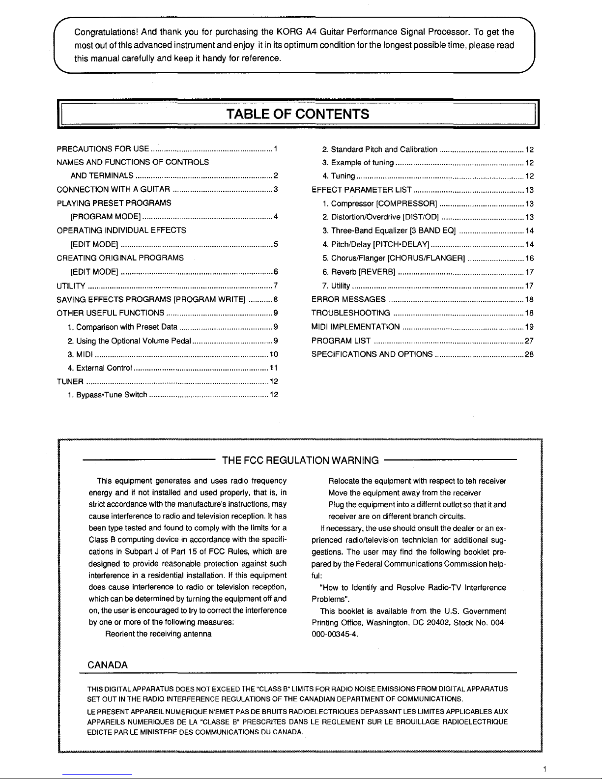
Congratulations! And thank you for purchasing the KORG A4 Guitar Performance Signal Processor. To get the
most out of this advanced instrument and enjoy it
in
its optimum condition for the longest possible time, please read
this
manual carefully and keep it handy for reference.
II
TABLE OF CONTENTS
PRECAUTIONS FOR USE
...
: .................................................... 1
2.
Standard Pitch and Calibration .......................................
12
NAMES AND FUNCTIONS OF CONTROLS
3. Example of tuning ...........................................................
12
AND TERMINALS ............................................................... 2
4.
Tuning ............................................................................. 12
CONNECTION WITH A GUITAR .............................................. 3
EFFECT PARAMETER
LIST ...................................................
13
PLAYING PRESET PROGRAMS
1.
Compressor [COMPRESSOR] .......................................
13
[PROGRAM MODE] ............................................................ 4
2.
Distortion/Overdrive [DIST/OD] ......................................
13
OPERATING INDIVIDUAL EFFECTS
3.
Three-Band Equalizer
[3
BAND EO] .............................. 14
[EDIT MODE] ...................................................................... 5
4.
Pitch/Delay [PITCH•DELA
Y]
........................................... 14
CREATING ORIGINAL PROGRAMS
5.
Chorus/Fianger [CHORUS/FLANGER] .......................... 16
[EDIT MODE] ...................................................................... 6
6.
Reverb [REVERB] .......................................................... 17
UTILITY ..................................................................................... 7
7.
Utility ............................................................................... 17
SAVING EFFECTS PROGRAMS [PROGRAM WRITE] ........... 8 ERROR MESSAGES .............................................................. 18
OTHER USEFUL FUNCTIONS ................................................. 9 TROUBLESHOOTING ............................................................ 18
1.
Comparison with Preset Data ........................................... 9 MIDI IMPLEMENTATION ........................................................ 19
2.
Using the Optional Volume Pedal ..................................... 9
PROGRAM
LIST ..................................................................... 27
3.
MIDI ................................................................................
10
SPECIFICATIONS AND OPTIONS ......................................... 28
4.
External Control ..............................................................
11
TUNER .................................................................................... 12
1 .
Bypass• Tune Switch ....................................................... 12
THE
FCC
REGULATION
WARNING
---------
This equipment generates and uses radio frequency
energy and
if
not installed and used properly, that is, in
strict accordance with the manufacture's instructions, may
cause interference
to
radio and television reception. It has
been type tested and found to comply with the
limits for a
Class B computing device in accordance with the specifications
in
Subpart J of Part
15
of FCC Rules, which are
designed to provide reasonable protection against such
interference in a residential
installation.
If
this equipment
does cause interference to radio or television reception,
which can be determined by turning the equipment off and
on, the user is encouraged
to
try to correct the interference
by one or more of the
following measures:
Reorient the receiving antenna
CANADA
Relocate the equipment with respect to teh receiver
Move the equipment away from the receiver
Plug the equipment into a differnt outlet so that
it
and
receiver are on different branch circuits.
If
necessary, the use should onsult the dealer or an exprienced radio/television technician for additional suggestions. The user may find the
following booklet pre-
pared by the
Federal Communications Commission help-
ful:
"How to Identify and Resolve Radio-TV Interference
Problems".
This booklet is available from the U.S. Government
Printing Office, Washington,
DC
20402, Stock No. 004-
000-00345-4.
THIS DIGITAL APPARATUS DOES NOT EXCEED THE "CLASS B" LIMITS FOR RADIO NOISE EMISSIONS FROM DIGITAL APPARATUS
SET
OUT
IN THE RADIO INTERFERENCE REGULATIONS OF THE CANADIAN DEPARTMENT OF COMMUNICATIONS.
LE PRESENT APPAREIL NUMERIQUE N'EMET PAS DE BRUITS RADIOELECTRIQUES DEPASSANT LES LIMITES APPLICABLE$ AUX
APPAREILS NUMERIQUES DE LA "CLASSE B" PRESCRITES DANS LE REGLEMENT SUR LE BROUILLAGE RADIOELECTRIQUE
EDICTE
PARLE
MINISTERE DES COMMUNICATIONS DU CANADA.
II
I
I
I
II
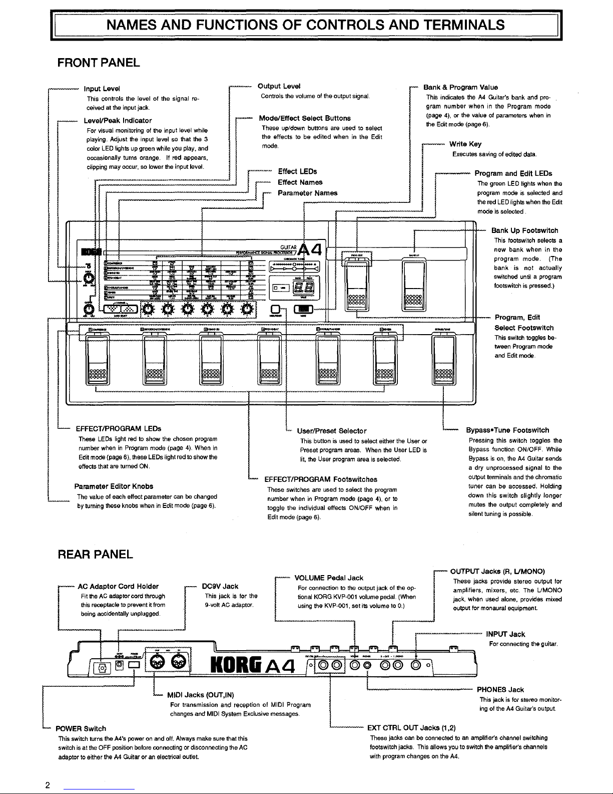
NAMES AND FUNCTIONS OF CONTROLS AND TERMINALS
II
FRONT
PANEL
-
Input
Level
--
This controls
the
level of
the
signal
re-
ceived at
the
input jack.
LeveVPeak
Indicator
-
I
For
visual monitoring
of
the input
level
while
playing. Adjust the input level so that the 3
color
LED
lights
up
green
while
you
play,
and
occasionally turns orange. If red appears,
clipping
may
occur,
so
lower
the
input level.
,.....-·
I
I
I
-
I
L
&!
.........-
-'11
-
·~
..
'"'
~
.
..
-·
-
-
•.
~
··:::·:-:.:·:·.
' '
0
0·
·0·
< J
_
_,
A 0 C 0 I f
r-
-
-
.,.
__
r-----
eJ
t--
ggggg
ggggg
~
I
~
I
L
EFFECT/PROGRAM LEOs
These
LEOs
light
red
to
show the chosen
program
number
when
in
PrOgram
mode (page
4).
When
in
Edit
mode
(page
6),
these
LEOs
light
red
to
show
the
0 t
ut
L
up
eve
Controls
the
volume
of
the output signal.
Mode/Effect
Select
Buttons
These up/down buttons are used
to
select
the effects
to
be edited when
in
the Edit
mode.
Effect
LEOs
Effect
Names
r
Parameter
Names
GUITAR,J.
4
r,:;;.,';;,-
K~
·•
Q-
-·
l
:---
IEJoJ
r--
00000
00000
00000
Q-
~-
9=
--·
-
-
r----- r----- r-----
00000
ggggg
~
00000
00000
00000
~
~
User/Preset
Selector
r-
Bank & Program
Val
ue
l
,--"""
This indicates the
A4
gram number when
in
Guitar's bank and pro-
the Program mode
of parameters when in
(page
4), or the value
the
Edit
mode
(page
6).
[
Write
Key
Executes
savi
ng
of
edited
data.
Prog
ram
and
Edit
LEOs
green
LED
lights
when
the
am mode is selected and
I
The
progr
the
ned
LED
lights
when
the
Edit
e
is
selected
mod
~
Bank
Up
Footswitch
This footswitch selects a
new
bank
when
in
the
program mode. (The
bank is not actually
switched
until
a program
tootswitch
is
pressed.)
I
-
r-----
&§§§§
¥
..._
Bypass
Program, Edit
Select
Footswitch
This switch toggles be-
tween
Program
mode
and
Edit
mode.
•
Tune
Footswitch
This button
is
used
to
select either
the
User
or
Press
in
Preset program
areas.
When
the
User
LED
is
Bypass
lit,
the
User
program
area
is
selected.
Bypass
i
L
effects that
are
turned
ON.
Parameter
Editor
Knobs
The
value
of
each
effect parameter
can
be
changed
by
turning these
knobs
when
in
Edit
mode
(page
6).
'-
EFFECT/PROGRAM
Footsw;tches
These
switches
are
used to select
the
program
number when
in
Program
mode
(page
4),
or
to
toggle the individual effects ON/OFF when
in
Edit
mode
(page
6).
a
dry
u
output t
g this switch toggles the
function ON/OFF.
While
s
on,
the
A4
Guitar sends
nprocessed signal to the
erminals and the chromatic
tuner can be accessed. Holding
down this switch slightly longer
mutes
the
output completely
and
silent
tuning
is
possible.
2
REAR
PANEL
I
~~
:::~t:~a~:~~~o~'::~gh
this receptacle
to
prevent it
from
being
accidentally unplugged.
OC9V
Jack
This jack
is
for
the
9~volt
AC
adaptor.
I
OUTPUT
Jacks
{R,
L/MONO)
[
VOLUME Pedal
Jack
I
These
Jacks
provide
stereo
output
for
For connectton
to
the
output
Jack
of
the
op- amphfters, mtxers, etc The UMONO
lienal
KORG
KVP~001
volume
peda~l
(When
Jack,
when used alone,
provtdes
mtxed
usmg
the
KVP-001,
set
tts
volume
to
0)
output for monaural equtpment
POWER
Switch
KORIA4
For transmission and reception of
MIDI
Program
changes and
MIDI
System Exclusive messages.
This
switch
turns
the
A4's power
on
and
off.
Always make sure that this
switch
is
at
the
OFF
position before connecting or disconnecting the
AC
adaptor
to
either
the
A4
Guitar or
an
electrical outlet.
--~--
INPUT
Jack
....._
__
EXT
CTRL
OUT
Jacks
(1
,2)
For
connecting
the
guttar
PHONES
Jack
This
jack
is
for stereo
monitor~
ing
of
the
A4
Guitar's output.
These
jacks
can
be
connected
to
an
amplifier's channel switching
footswitch jacks.
This
allows
you
to switch
the
amplifier's channels
with program changes
on
the
A4.

II
CONNECTION WITH A GUITAR
1. Connect a guitar to the INPUT jack on the A4's rear panel.
2. Connect your guitar amplifier(s) to the OUTPUT jack(s)
on
the A4's rear panel. (For best results, use both jacks for stereo output to two
amplifiers. For monaural (one amplifier) operation, connect to the
UMONO
jack
only.)
3. For volume pedal control, connect the optional KORG KVP-001 volume pedal. (See page 9 for more details.)
4. Input signals can be monitored
in
stereo
by
connecting a pair
of
stereo headphones to the PHONES jack.
5. After completing connection with instruments and equipment, turn
on
the A4 Guitar's power.
6.
When playing the guitar, the peak indicator, which moves
in
accord with the input volume level, will go from green to yellow to orange to red.
When increasing the input
volume or playing the guitar strongly, please
do
not allow the indicator to go into the red area.
7.
Please set the output volume appropriately. Following the above will allow for performance conditions.
NOTE: When turning the A4 Guitar on and off, make sure to turn all volume controls on all instruments and equipment down as far as they will
go.
®
HDRiiAll
~~-
=
II
3
PLAYING PRESET PROGRAMS
[PROGRAM MODE]
About Preset Programs
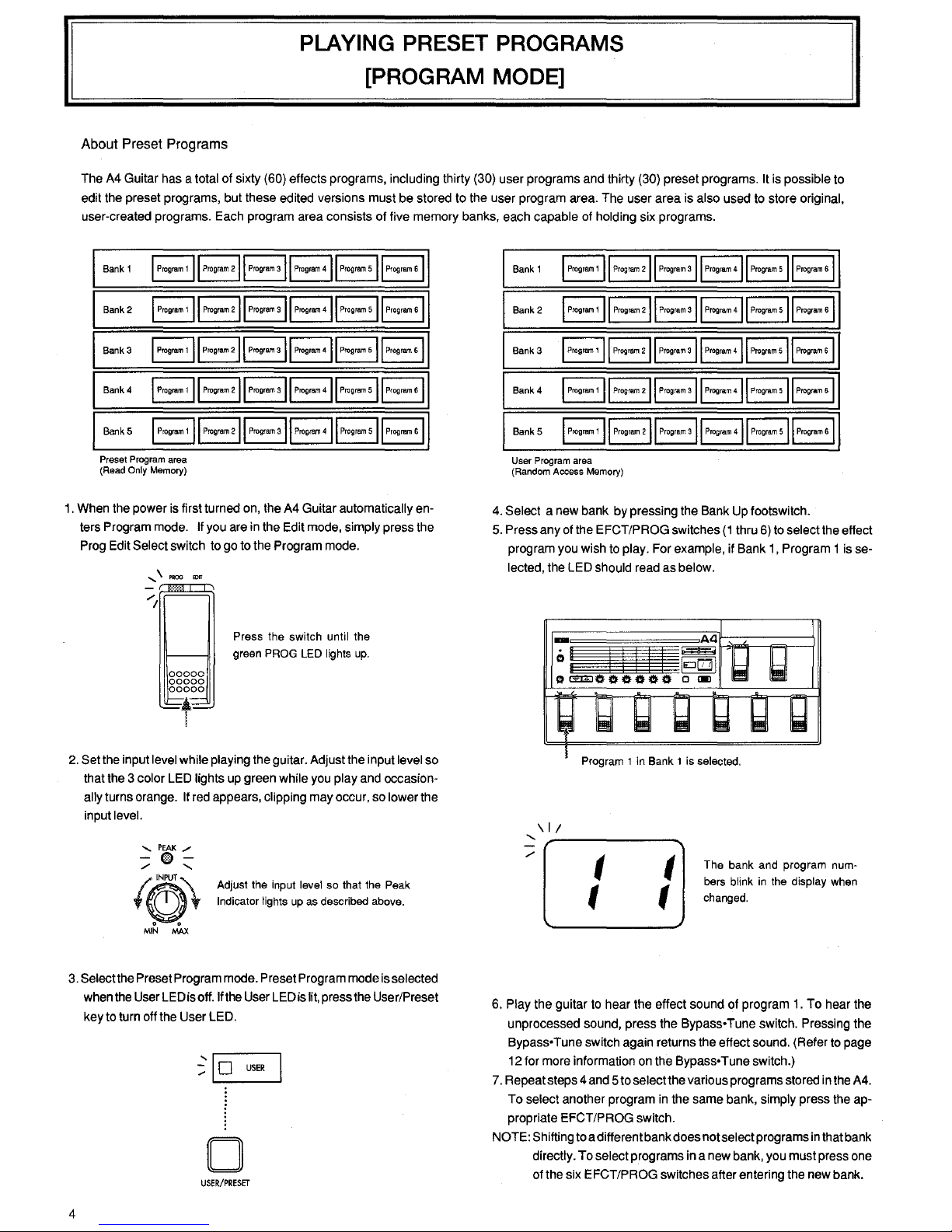
The
A4
Guitar
has
a total of sixty
(60)
effects programs, including thirty
(30)
user programs
and
thirty
(30)
preset programs.
It
is
possible
to
edit
the
preset programs, but these edited versions must
be
stored
to
the user program
area.
The
user area
is
also used
to
store original,
user-created programs.
Each
program area consists of five memory banks,
each
capable
of
holding six programs.
Bank
1
BBBBBB
Bank
2
BBBBBB
Bank3
BB~BB~
Bank4
EJEjB~~B
BankS
BBBBBB
Preset Program area
(Read
Only Memory)
1.
When
the
power
is
first turned
on,
the
A4
Guitar automatically
en-
ters Program
mode.
If
you
are
in
the
Edit
mode,
simply press
the
Prog
Edit
Select switch
to
go
to
the
Program
mode.
....... \ PROG
Press the switch until the
green
PROG
LED
lights
up.
2.
Setthe input
level
while playing
the
guitar. Adjust
the
input
level
so
that
the
3 color
LED
lights
up
green while
you
play
and
occasion-
ally
turns orange.
If
red
appears, clipping
may
occur,
so
lower
the
input level.
Adjust the input level so that the Peak
Indicator
lights
up
as
described above.
3.
Select
the
Preset Program
mode.
Preset Program
mode
is
selected
when
the
User
LED
is
off.
If
the
User
LED
is
lit,
press
the
User/Preset
key
to
turn
off
the
User
LED.
~~
0
USER
0
USER/PRESET
4
Bank 1
I
Program
1
II
Progmm
211
Progmm
311
Program
411
Progmm
sll
Progmm
sl
Bank2
I
Progmm
1
II
Progmm
211
Progmm
all
Progmm
411
Progmm
sll
Program
sl
Bank 3
I
Progmm
1
II
Progmm
211
Progmm
all
Program
411
Progmm
sll
Prog~
sl
Bank4
I
Progr&n
1
II
Progmm
211
Progmm
311
Progmm
411
Progmm
s)l
Progmm
s)
BankS
I
Progmm
1
II
Program
211
Program
sll
Progmm
411
Program
sll
Progmm
sl
User Program area
(Random Access Memory)
4.
Select a
new
bank
by
pressing the
Bank
Up
footswitch.
5.
Press any
of
the
EFCT/PROG switches
(1
thru
6)
to
select
the
effect
program
you
wish
to
play.
For
example, if
Bank
1,
Program 1
is
se-
lected,
the
LED
should
read
as
below .
\I/
'
I
t
I
t
The bank and program numbers blink
in
the display when
changed.
6.
Play
the guitar
to
hear
the
effect sound
of
program
1.
To
hear
the
unprocessed sound, press
the
Bypass• Tune switch. Pressing the
Bypass• Tune switch
again
returns
the
effect
sound.
(Refer
to
page
12
for
more
information
on
the
Bypass• Tune switch.)
7.
Repeat steps 4
and
5 to select
the
various programs
stored
in
the
A4.
To
select another program
in
the
same
bank,
simply press
the
ap-
propriate EFCT/PROG switch.
NOTE: Shifting
to
a different bank does not select programs
in
that
bank
directly.
To
select programs
in a new
bank,
you
must
press
one
of
the
six
EFCT/PROG switches after entering
the
new
bank.
OPERATING INDIVIDUAL EFFECTS
[EDIT MODE]
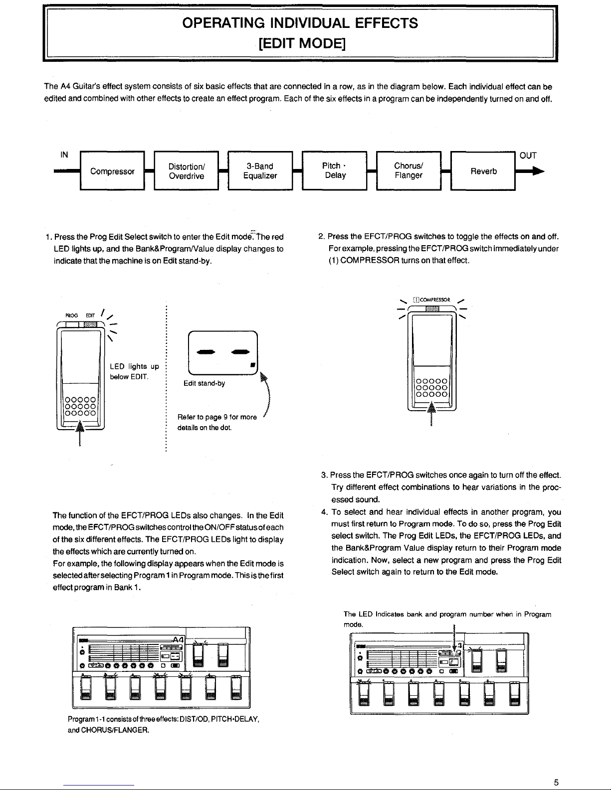
The A4 Guitar's effect system consists
of
six basic effects that are connected in a row,
as
in
the diagram below. Each individual effect can be
edited and combined with other effects to create an effect program. Each of the six effects in a program can be
independently turned on and off.
IN
-
Compressor
-
Distortion/
-
3-Band
Overdrive
Equalizer
1.
Press the Prog Edit Select switch to enter the Edit mode':'
the
red
LED
lights up, and the Bank&Program/Value display changes to
indicate that the machine is on Edit stand-by.
PROG
EDIT
I/
00000
00000
00000
~t~
......
\
LED
lights
up
below EDIT.
B
'""
.....
, )
Refer to page 9 for more
details on the dot.
The function of the EFCT/PROG LEDs also changes. In the Edit
mode, the
EFCT/PROG switches control the ON/OFF status of each
of
the six different effects. The EFCT/PROG LEDs light to display
the effects which are currently turned on.
For
example, the following display appears when the Edit mode is
selected after selecting Program 1 in Program mode. This is the first
effect program
in
Bank 1.
Program
1-1
consists ofthreeeffects: DIST/OD. PITCH•DELAY,
and CHORUS/FLANGER.
1-
OUT
Pitch·
1-'
Chorus/
1-'
Reverb
......
Delay Flanger
2. Press the EFCT/PROG switches to toggle the effects on and off.
For
example, pressing the EFCT/PROG switch immediately under
(1)
COMPRESSOR turns on that effect.
......
[jJCOMPRESSOR
/
00000
00000
00000
~t~
3. Press the EFCT/PROG switches once again to turn off the effect.
Try different effect combinations to hear variations
in
the proc-
essed sound.
4. To
select and hear individual effects in another program, you
must first return to Program mode. To do so, press the Prog Edit
select switch. The Prog Edit LEOs, the EFCT/PROG LEDs, and
the Bank&Program
Value display return to their Program mode
indication. Now, select a new program and press the Prog Edit
Select switch again to return to the Edit mode.
The LED Indicates bank and program number when in Program
mode.
5
CREATING ORIGINAL PROGRAMS
[EDIT MODE]
About
Parameters
and
Editing
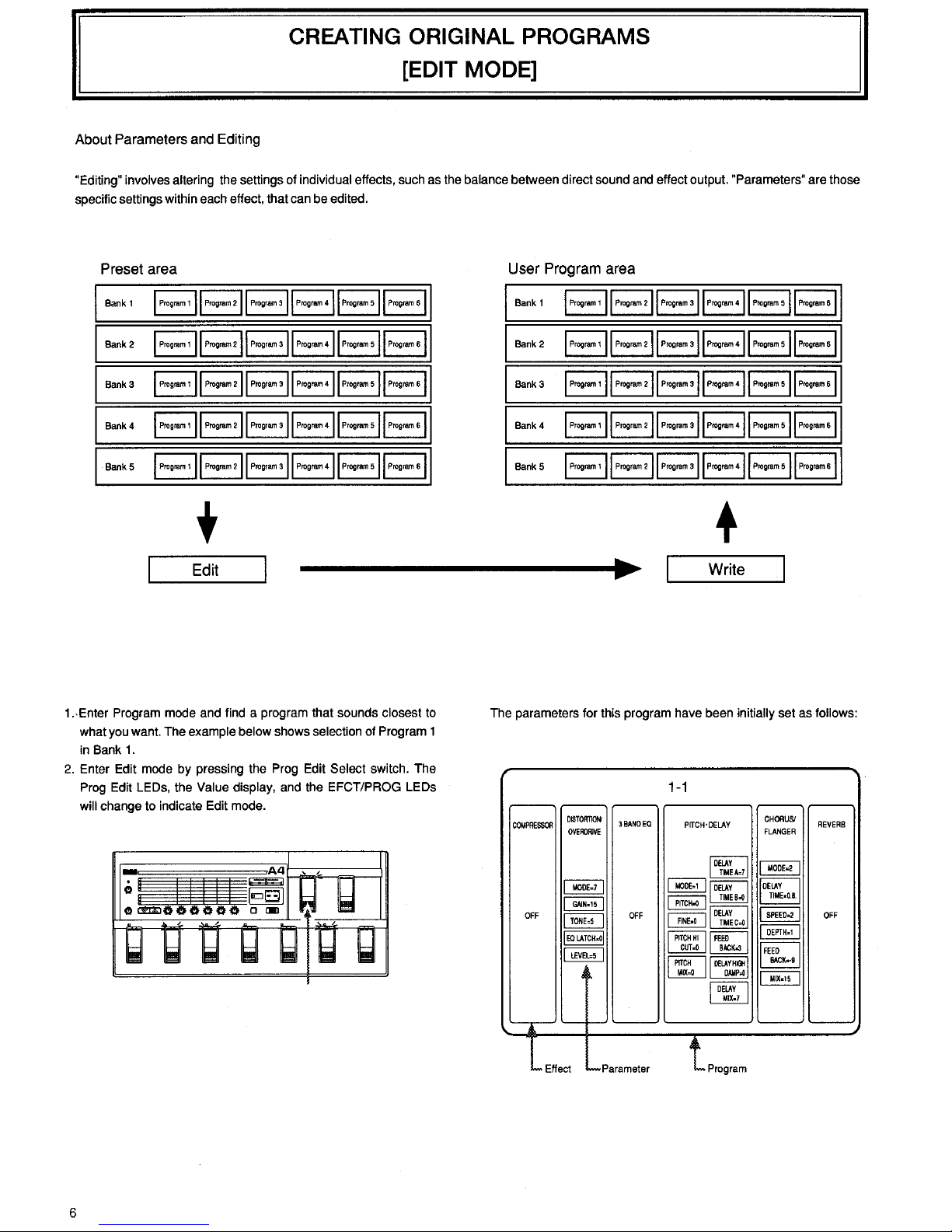
"Editing" involves altering the settings of individual effects, such as the balance between direct sound and effect output. "Parameters" are those
specific settings within each effect, that can be edited.
Preset area
Bank
1
I
Prog~m
1
II
Progmm
211
Progrmn
all
Progmm
411
Progmm
sll
Progmm
sl
Bank2
I
Progmm1
II
Prog~211
Progr~all
Prog~411Progmmsi1Prog~sl
Bank3
I
Progmm
1
II
Progmm
211
Program
a((
Progmm
411
Progmm
sll
Progmm
sl
Bank4
I
Progmm
1
II
Progmm
211
Program
all
Progmm
411
Progmm
sll
Progmm
sl
Bank5
I
Prog~
1
II
Progmm
211
Program
all
Progmm
411
Progmm
sll
Progmm
sl
Edit
1.-Enter Program mode and find a program that sounds closest to
what you want. The example below shows selection of Program 1
in Bank
1.
2.
Enter Edit mode by pressing the Prog Edit Select switch. The
Prog Edit LEOs, the Value display, and the EFCT/PROG LEOs
will change to indicate Edit mode.
6
User
Program
area
Bank
1
I
Progmm
1
II
Progmm211
Progmmall
Progmm411
Progmmsll
Progmmsl
Bank2
I
Progmm
1
II
Program
211
Progmm
all
Progmm
411
Prog~
sll
Progmm
sl
Bank3
I
Progrem1
II
Progmm211
Progmmall
Progmm411
Progmmsll
Progmms(
Bank4
I
Progrem
1
II
Progrem
211
Progmm
all
Progmm
411
Progmm
sll
Progmm
sl
Bank5
I
Progrem
1
II
Program
211
Progmm
all
Progmm
411
Program
sll
Progmm
sl
+
Write
The parameters for this program have been initially set as follows:
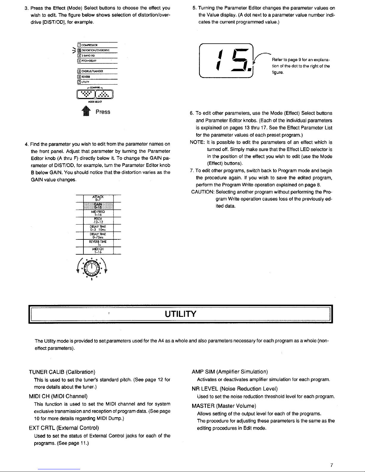
3. Press the Effect (Mode) Select buttons to choose the effect you
wish to edit. The figure below shows selection of distortion/overdrive
[DIST/ODJ, for example.
[I)
COM?RESSOR
?
ll)
DISTORTION/OVERDRIVE
@)JBANDEQ
ffii'ITCH•OElAY
[IlCI-ORUS/FLANGER
[!)REVeRB
l!lliTIUTY
..
Press
4.
Find the parameter you wish to edit from the parameter names on
the front panel. Adjust that parameter by turning the Parameter
Editor knob (A thru
F)
directly below it. To change the GAIN pa-
rameter of
DIST/OD, for example, turn the Parameter Editor knob
B below
GAIN. You should notice that the distortion varies as the
GAIN value changes.
ATTACK
()..7
DElAY
TIME
0-75ms
REVERB
TIME
h
MIDICH
1-16
(:(!):)
o B o
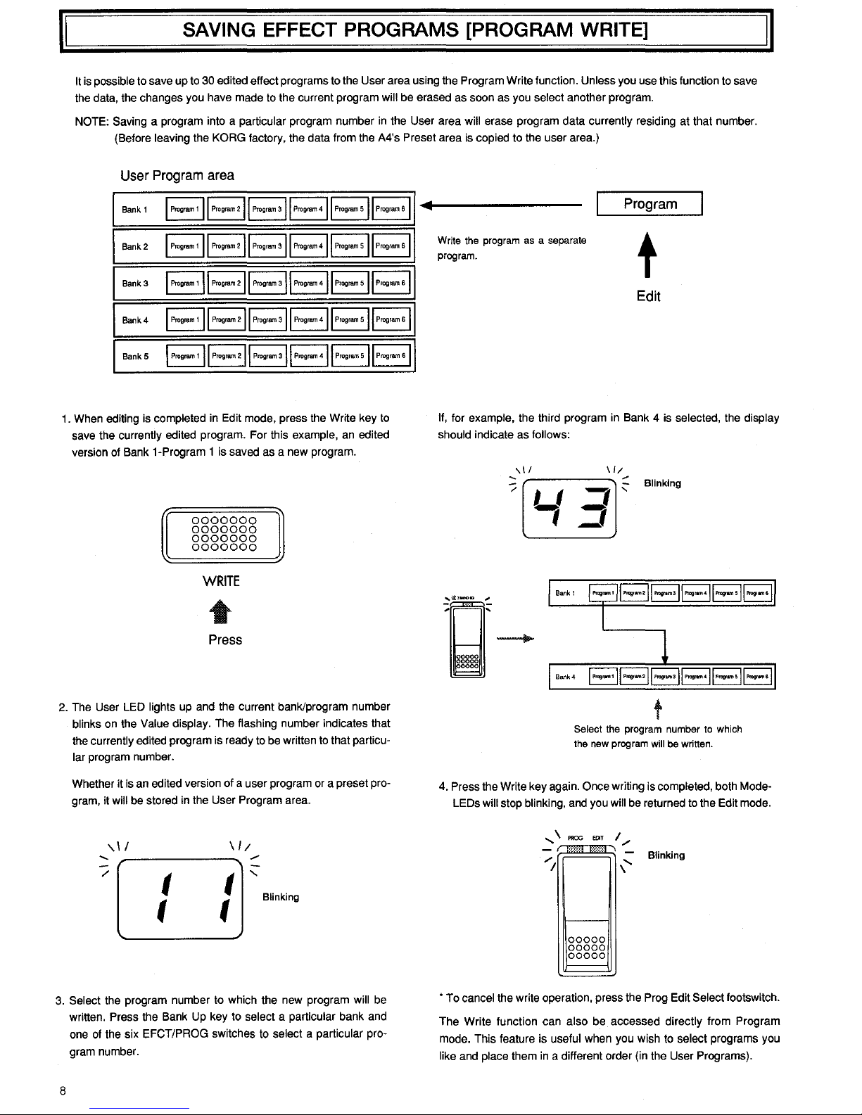
5. Turning the Parameter Editor changes the parameter values
on
the Value display. (A dot next to a parameter value number indicates the current programmed value.)
t L
~Refer
to
page 9 for
an
explana·
t J tion of the dot
to
the right of
the
.-
• figure.
6.
To edit other parameters, use the Mode (Effect) Select buttons
and Parameter Editor knobs. (Each of the individual parameters
is explained on pages
13
thru 17. See the Effect Parameter List
for the parameter values of each preset program.)
NOTE:
It
is possible to edit the parameters of an effect which is
turned off.
Simply make sure that the Effect LED selector
is
in
the position of the effect you wish to edit (use the Mode
(Effect) buttons).
7. To edit other programs, switch back
to
Program mode and begin
the procedure again.
If
you wish to save the edited program,
perform the Program Write operation explained on page
8.
CAUTION: Selecting another program without performing the Pro-
gram Write operation causes loss of the previously edited data.
II
UTILITY
II
The Utility mode is provided
to
set parameters used for the
A4
as a whole and also parameters necessary for each program
as
a whole (non-
effect parameters).
TUNER
CALIS
(Calibration)
This is used to set the tuner's standard pitch. (See page
12
for
more details about the tuner.)
MIDI
CH
(MIDI
Channel)
This function is used to set the MIDI channel and for system
exclusive transmission and reception of program data.
(See page
10 for more details regarding MIDI Dump.)
EXT
CRTL
(External
Control)
Used to set the status of External Control jacks for each of the
programs.
(See page 11.)
AMP
SIM
(Amplifier
Simulation)
Activates or deactivates amplifier simulation for each program.
NR
LEVEL
(Noise
Reduction
Level)
Used to set the noise reduction threshold level for each program.
MASTER
(Master
Volume)
Allows setting of the output level for each of the programs.
The procedure for adjusting these parameters
is
the same
as
the
editing procedures in Edit mode.
7
II
SAVING EFFECT PROGRAMS [PROGRAM WRITE]
II
It
is
possible to save up to 30 edited effect programs to the User area using the Program Write function. Unless you use this function to save
the data, the changes you have made to the current program
will be erased as soon as you select another program.
NOTE: Saving a program into a particular program number
in
the User area will erase program data currently residing at that number.
(Before
leaving the KORG factory, the data from the A4's Preset area
is
copied to the user area.)
User
Program
area
Bank
1 I
Prog~
1
II
Prog~211
Program3ll
Progrem4ll
Progremsll
Progmm
sl
Bank2
I
Progmm
1
II
Progmm
'II
Prog•am
'II
Prog•am
·II
Prog•am
sll
Progmm
·II
Bank3
I
Progmm
1
II
Progmm
211
Program
311
Progrem
411
Progrem
sll
Progrem
sl
Bank4
I
Progrem
1
II
Progmm
211
Program
sll
Progrem
411
Progrem
sll
Program
sl
BankS
I
Progmm
1
II
Progmm
211
Program
311
Progrem
411
Progrem
sll
Progrem
sl
1. When editing is completed in Edit mode, press the Write key
to
save the currently edited program. For this example, an edited
version of Bank 1-Program 1 is saved as a new program.
0000000
0000000
0000000
0000000
WRITE
Press
2. The User LED lights up and the current bank/program number
blinks on the Value display. The flashing number indicates that
the
currently edited program is ready to be written
to
that particu-
lar program number.
Whether it
is
an edited version of a user program or a preset pro-
gram, it
will be stored in the User Program area.
\.II
......
/
t
t
t
t
Blinking
3. Select the program number to which the new program will be
written. Press the Bank Up key to
select a particular bank and
one of the six EFCT/PROG switches to
select a particular pro-
gram number.
8
Program
Write the program
as
a separate
program.
t
Edit
II, for example, the third program in Bank 4 is selected, the display
should
indicate as follows:
II/
-;;
,.--------,---
~
'-/~
Blinking
t
Select the program number
to
which
the new program
will
be
written.
4. Press the Write key again. Once writing is completed, both ModeLEDs
will stop blinking, and you will be returned to the Edit mode.
PROO
EOIT
I/
00000
00000
00000
Blinking
• To cancel the write operation, press the Prog Edit Select footswitch.
The Write function can
also be accessed directly from Program
mode. This feature is
useful when you wish
to
select programs you
like and place them
in
a different order (in the User Programs).
 Loading...