

Korg 73key, 88key Owner's Manual

73key
88key
Owner’s manual
Manuel d’utilisation
Bedienungsanleitung
取扱説明書

Precautions
Location
Using the unit in the following locations can result in a
malfunction.
• In direct sunlight
• Locations of extreme temperature or humidity
• Excessively dusty or dirty locations
• Locations of excessive vibration
• Close to magnetic fields
Interference with other electrical devices
Radios and televisions placed nearby may experience reception interference. Operate this unit at a suitable distance
from radios and televisions.
Handling
To avoid breakage, do not apply excessive force to the
switches or controls.
Care
If the exterior becomes dirty, wipe it with a clean, dry cloth.
Do not use liquid cleaners such as benzene or thinner, or
cleaning compounds or flammable polishes.
Keep this manual
After reading this manual, please keep it for later reference.
Keeping foreign matter out of your equipment
Never set any container with liquid in it near this equipment. If liquid gets into the equipment, it could cause a
breakdown, fire, or electrical shock. Be careful not to let
metal objects get into the equipment.
Notice regarding disposal (for EU)
If this “crossed-out wheeled bin” symbol is shown
on the product or in the operating manual, you
must dispose of the product in an appropriate
way. Do not dispose of this product along with
your household trash. By disposing of this product
correctly, you can avoid environmental harm or
health risk. The correct method of disposal will depend on your locality, so please contact the appropriate local authorities for details.
THE FCC REGULATION WARNING (for USA)
This equipment has been tested and found to comply
with the limits for a Class B digital device, pursuant to
Part 15 of the FCC Rules. These limits are designed to
provide reasonable protection against harmful interference in a residential installation. This equipment generates, uses, and can radiate radio frequency energy and,
if not installed and used in accordance with the instructions, may cause harmful interference to radio communications. However, there is no guarantee that interference will not occur in a particular installation. If this
equipment does cause harmful interference to radio or
television reception, which can be determined by turning the equipment off and on, the user is encouraged to
try to correct the interference by one or more of the following measures:
• Reorient or relocate the receiving antenna.
• Increase the separation between the equipment and
receiver.
• Connect the equipment into an outlet on a circuit different from that to which the receiver is connected.
• Consult the dealer or an experienced radio/TV technician for help.
Unauthorized changes or modification to this system
can void the user’s authority to operate this equipment.
* Company names, product names, and names of formats
etc. are the trademarks or registered trademarks of their
respective owners.
3
KKS (KORG Komponent System)
This instrument is part of the KORG Komponent System.
This versatile system keeps all of the sound generating circuitry, all of the external connectors and even the power
supply together inside of the sound module (subsequently
referred to as the modsë). In this way, the instrument may
be played with the module section tilted up or lying flat. In
addition, the module section may be completely removed
and operated as an independent tone module, or used with
other KKS products for further convenience.
Parts and their functions
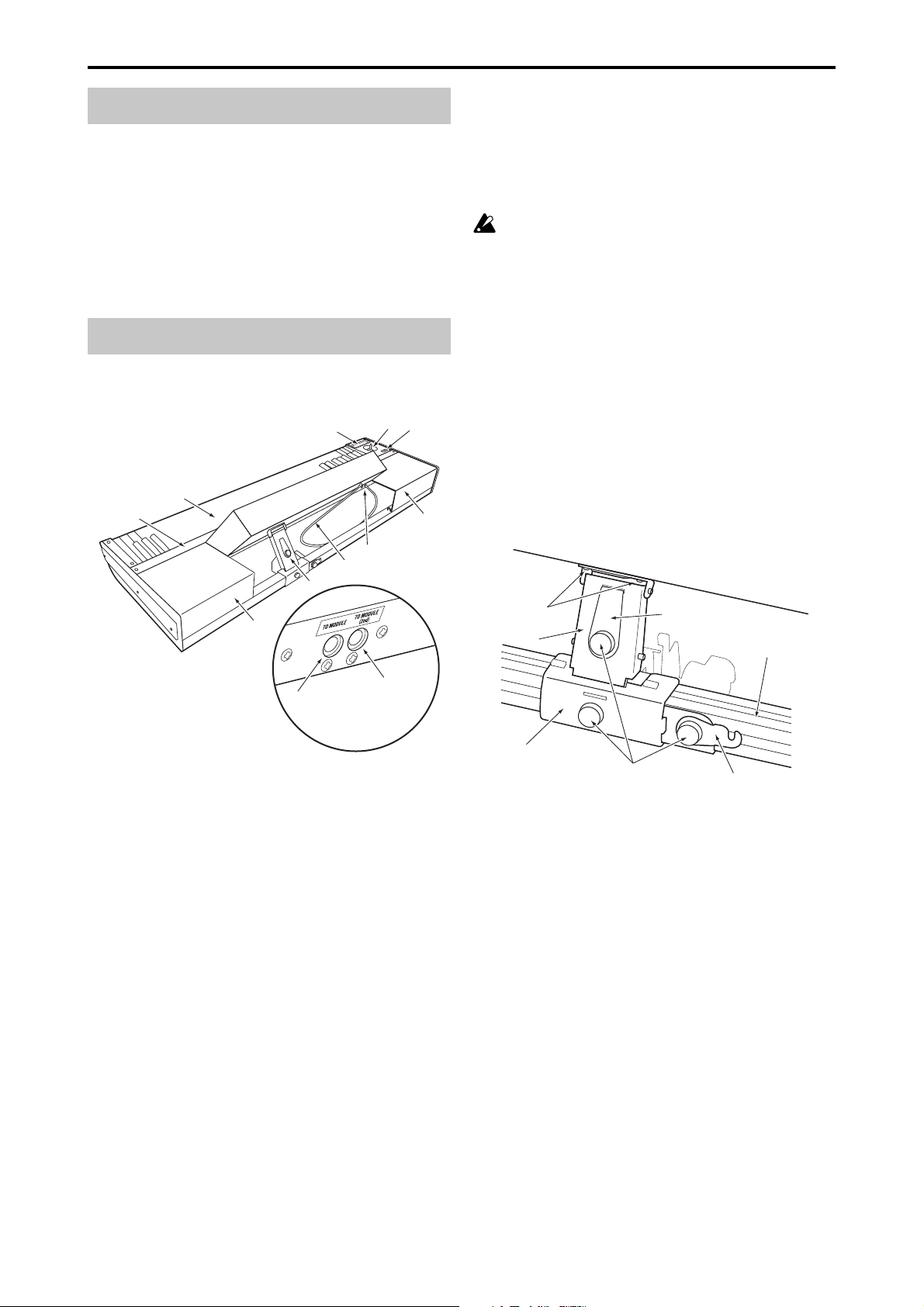
Keyboard Assembly
4
3
2
1
5
9
6.
TO MODULE connector/TO MODULE(2nd) connector
One end of the connecting cable (8) will plug into this jack,
and the other end will plug into the module’s TO KYBD
port. When connected, you’ll be able to use the keyboard
assembly’s keyboard, joystick, ribbon controller and
switches to control the module. If you’re using only one
module, connect it to the TO MODULE connector.
Certain modules may not support all of the controllers found on the keyboard assembly.
7. Connecting cable
This cable connects the keyboard assembly to the module.
8. Locking support
This part fastens the module to the keyboard assembly. The
support arm allows the rear of the module to be raised,
providing easy access to the panel controls, or lowered to
lie flat. In addition, the entire locking support can be moved
to any location along the rear rail, allowing the module to
be freely positioned.
9. Cover panels
When using a single module, these covers can be attached
to the keyboard assembly to provide a more finished look.
Locking support
6
7
8
9
TO MODULE(2nd) connector
TO MODULE connector
Expanded view of 6.
Connector area
1. Retaining bar
This part keeps the sound module and the cover panels
attached to the keyboard assembly. Four screws (M3 x 8)
with it locks.
2. Keyboard
73-key: semi-weighted
88-key: RH-3 (Real Weighted Hammer Action 3)
3. Ribbon controller
By touching or rubbing your finger on this ribbon you can
control various program and effect parameters on the connected module.
4. Joystick
By moving the joystick up/down/left/right you can control various program and effect parameters on the connected module.
5. SW1/SW2
You can use these switches to control various program or
effect parameters on the connected module, or to turn the
joystick or ribbon controller’s Lock function on/off.
6
2
1
3
Rear rail
5
4
1. Bracket
This part is attached to the rear rail of the keyboard assembly. It can be moved horizontally so that you can re-position the module.
2. Support arm
This part supports the module when it’s in the raised position.
3. Lock plate
This secures the arm when you’re using the module in the
raised position.
4. Latch
This secures the module when it’s in the lowered/stored
position, lying flat on the keyboard assembly.
5. Screws A
These fasten their respective parts.
6. Screws B
These are two screws (M4 x 6) that attach the support arm
to the module.
4
Caution when adjusting the module
4. Loosen the screw A that holds the lock plate, turn the lock
Please observe the following cautions in order to ensure
safe and correct assembly and disassembly.
Please observe the following cautions in order to ensure safe and correct use, assembly and disassembly.
Be careful not to pinch your hands or fingers while
raising or lowering the module.
Be sure that the module is powered-off when you connect or disconnect the cable between the keyboard
assembly and the module. If you connect or disconnect this cable while the power is on, the module may
stop operating correctly.
Before you proceed, be sure to read and follow the
“Safety precautions” found earlier in this manual.
plate 180 degrees as shown, and fit it into the slot in the
bracket.
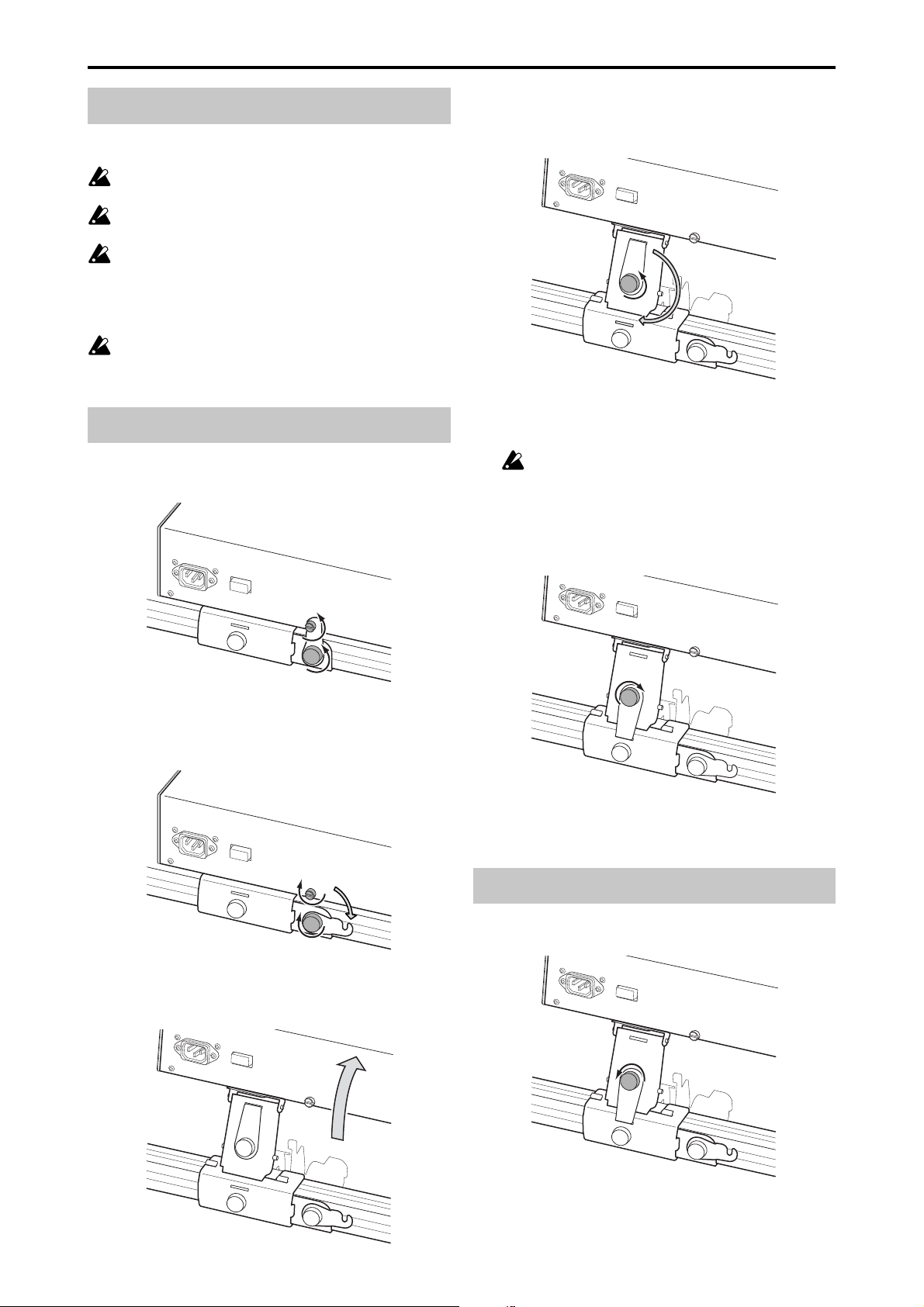
Raising the module
1. Loosen both of the latch screws; the one securing the latch
to the module, and the one connected to the bracket.
2. Rotate the latch to the side as shown in the illustration,
and tighten the screw A to fasten it in place. Also tighten
the screw on the module so that it does not fall out.
5. Tighten the lock plate screw A to secure it in place.
This step is very important. If you move the keyboard assembly or apply excessive force to the
module without fastening the lock plate to the
bracket, the module may fall down resulting in
damage or injury. For safety, fit the lock plate into
the bracket and fasten it with the screw A.
3. Using the handle located on the rear panel, lift the mod-
ule until it stops; and release the handle.
Lowering the module
1. Loosen the screw A securing the lock plate.
5
2. Rotate the lock plate 180 degrees, fit it into the slot of the
support arm, and tighten the screw to fasten it.
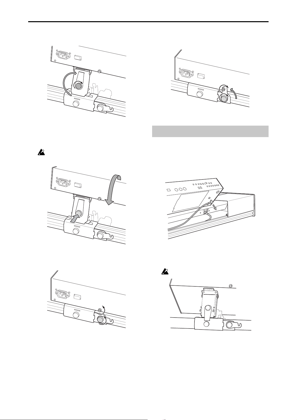
5. As shown in the illustration, rotate the latch to the verti-
cal position and slide it under the screw on the module.
Then tighten both screws.
3. As shown in the illustration, lightly press in on the screw
A securing the lock plate to the arm, then gently lift the
module using the handle located on the rear panel and
release it. The module will slowly pivot down.
Be careful not to pinch your hand between the
module and the keyboard assembly.
4. Loosen the screw on the module and the screw A that
secures the latch.
Module removal
1. If the module is lying flat in the storage position, raise it
as described in steps 1–5 of “Raising the module.”
2. Disconnect the cable plug (L-shaped plug) connected to
the TO KYBD connector located on the bottom of the
module.
3. As shown in the illustration, use your Phillips (+) screw-
driver to remove the two screws B that attach the support
arm to the module.
Be careful not to lose the screws you remove.
6
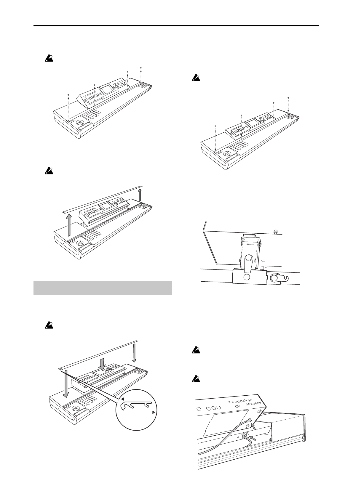
4. Use your Phillips (+) screwdriver to remove the four
screws that hold the retaining bar to the keyboard assembly.
Be careful not to lose the screws you remove.
5. Remove the retaining bar, and then lift the module using
both hands and remove it from the keyboard assembly.
Be careful not to pinch your hand between the
module and keyboard assembly.
2. Orient the retaining bar correctly as shown in the illustra-
tion, and place it on top of the module.
Align the screw holes in the retaining bar with the screw
holes in the keyboard assembly, and finger-tighten the
four screws. Finally, use your Phillips (+) screwdriver to
firmly tighten the four screws.
Don’t attempt to forcibly tighten the screws if the
screw holes are not aligned. Doing so may cause
damage to the unit.
3. Using the handle located on the rear panel, lift the mod-
ule up, align the screw holes in the module with the screw
holes in the support arm, and use your Phillips (+) screwdriver to install the two screws B that you removed when
detaching the module.
Module installation
1. Make sure that the support arm is folded down. Hold the
module in both hands and carefully place it on the keyboard assembly.
Be careful not to pinch your hand between the
module and keyboard assembly.
toward module
toward keyboard
Cross-section of
keyboard cover
4. Connect the included cable.
Connect the L-shaped plug of the cable to the TO KYBD
connector on the module, and connect the straight plug
to the TO MODULE connector on the keyboard assembly. If the TO MODULE connector is already being used
to connect another module, then use the TO MODULE
(2nd) connector.
The included cable is only for connecting the TO
KYBD connector to the TO MODULE or TO
MODULE (2nd) connector. Do not connect it to
any other connector.
If you’re using only one module, connect it to the
TO MODULE connector.
7

Locking support assembly
Cover panels
As shown in the illustration, the support arm, bracket and
latch parts fit together around the rear rail to form the locking support assembly. The raised tabs on the support arm
slide into the slots on the top of the bracket to hold everything together. To attach the locking support assembly, fasten the bracket to the support arm by sliding it horizontally (to the left) and tightening the screw on the bracket.
To r emove the locking support assembly, loosen the screw
and slide the bracket to the right to release the two pieces.
Make sure that the bracket is oriented correctly.
When performing this step, be careful not to cut your
hand on the metal parts.
The keyboard assembly can be used with or without the these
decorative “filler” panels. The cover panels will need to be
removed when using two modules. As shown in the illustration, the front edge of the cover panels are held in place
by the retaining bar. The back edge of the cover panels fit
into the channel on the top of the keyboard assembly’s rear
rail. To remove the cover panels, remove the retaining bar as
shown in step 4 of “Module removal” and lift off the cover
panels. Replace the retaining bar as described in step 2 of
“Module installation.” To replace the cover panels, remove
the retaining bar, place the back edge of the cover panels on
the top of the rear rail, and replace the retaining bar.
Rear rail
Caution when attaching the cover panel
Align the projections of the cover panel with the slot of the
rear rail, and press the cover panel into place.
If you press the cover panel when the projections are
not aligned with the slot, you may damage the projections.
8

If the cover panel comes open as shown below after you’ve
attached it, apply gentle pressure to the rear side and fit
the projections of the cover panel into the slot of the rear
rail.
Moving precautions
If you transport the keyboard assembly with the module in
the raised position, the lock plate must be fitted into the
slot on the bracket and secured in place by tightening the
lockplate screw. If you transport the keyboard assembly
with the module in the lowered (storage) position, the latch
must be connected to the module, with both the module
and bracket screws securely fastened.
If you transport the system without fastening these
screws, the module may move abruptly, causing damage or injury.
Caution when using multiple modules
■ When using more than one module, be sure both modules are turned off before connecting or disconnecting
either of the cables connected to the TO MODULE and
TO MODULE (2nd) connectors.
■ When using more than one module, the module connected to the TO MODULE connector must be turned on
in order for the module connected to the TO MODULE
(2nd) connector to be detected by the keyboard assembly and to function properly.
■ The lit/dark status of SW1/SW2 will reflect the state of
the module connected to the TO MODULE connector.
The SW1/SW2 lit/dark status of the module connected
to the TO MODULE (2nd) connector will not be reflected.
Be aware that the state of the TO MODULE (2nd) unit
may not necessarily match the SW1/SW2 status. If you
want the lit/dark indication to match the state of the TO
MODULE (2nd) unit, you would need to set the On/Off
and Toggle/Momentary setting of each Program, Combination, or Song of the module connected to the TO
MODULE (2nd) connector to be identical to the settings
of the module connected to the TO MODULE connector.
■ The Global mode menu command “After Touch Calibration” cannot be selected from an M3-M connected to the
TO MODULE (2nd) connector. In order to execute this
command, the M3-M must be connected to the TO MODULE connector.
Module raised
Module lowered (storage position)
Specifications
Keyboard 73-key: semi-weighted
88-key: RH-3 (Real Weighted
Hammer Action 3)
Controllers Joystick
Ribbon controller
SW1/SW2
Control connector TO MODULE connector
TO MODULE(2nd) connector
Dimensions (W x D x H) 73-key: 1189 x 371 x 128 mm
46.8 x 14.6 x 5.0 inches
88-key: 1425 x 442 x 128 mm
56.1 x 17.4 x 5.0 inches
Weight 73-key: 12.5 kg / 27.6 lbs.
(including cover panels and locking support)
88-key: 21.7 kg / 47.8 lbs.
(including cover panels and locking support)
Included items Connection cable x 1
* Appearance and specifications of this product are subject
to change without notice.
9
Précautions
Emplacement
L’utilisation de cet instrument dans les endroits suivants
peut en entraîner le mauvais fonctionnement.
• En plein soleil
• Endroits très chauds ou très humides
• Endroits sales ou fort poussiéreux
• Endroits soumis à de fortes vibrations
•A proximité de champs magnétiques
Interférences avec d’autres appareils électriques
Les postes de radio et de télévision situés à proximité peuvent par conséquent souffrir d’interférences à la réception.
Veuillez dès lors faire fonctionner cet appareil à une distance raisonnable de postes de radio et de télévision.
Maniement
Pour éviter de les endommager, manipulez les commandes et les boutons de cet instrument avec soin.
Entretien
Lorsque l’instrument se salit, nettoyez-le avec un chiffon
propre et sec. Ne vous servez pas d’agents de nettoyage
liquides tels que du benzène ou du diluant, voire des produits inflammables.
Conservez ce manuel
Après avoir lu ce manuel, veuillez le conserver soigneusement pour toute référence ultérieure.
Evitez toute intrusion d’objets ou de liquide
Ne placez jamais de récipient contenant du liquide près de
l’instrument. Si le liquide se renverse ou coule, il risque de
provoquer des dommages, un court-circuit ou une électrocution. Veillez à ne pas laisser tomber des objets métalliques dans le boîtier (trombones, par ex.).
* Les noms de sociétés, noms de produits et noms de for-
mats, etc. dans ce manuel sont des marques de fabrique
ou des mar-ques déposées de leurs propriétaires respectifs.
Notice concernant l’élimination du produit (UE seulement)
Si ce symbole “Poubelle barrée” est imprimé sur le
produit ou dans le manuel de l’utilisateur, vous
devez vous débarrasser du produit de la manière
appropriée. Ne jetez pas ce produit avec vos ordures ménagères. En vous débarrassant correctement du produit, vous préviendrez les dommages
environnementaux et les risques sanitaires. La méthode correcte d’élimination dépendra de votre
lieu d’habitation, aussi veuillez contacter les autorités locales concernées pour les détails.
10
 Loading...