

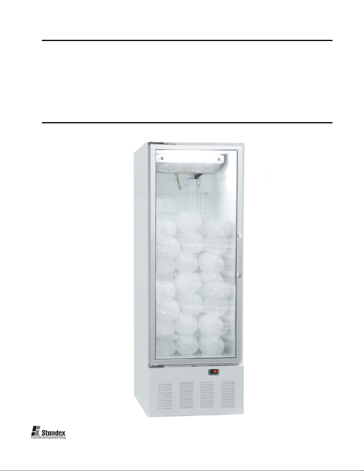
ICE MERCHANDISER
Installation, Operation and
Maintenance Instructions
1 1/08 N138647

INSPECTION
When the equipment is received, all items should be carefully checked against the bill of
lading to insure all crates and cartons have been received. All units should be inspected
for concealed damage by uncrating the units immediately. If any damage is found, it
should be reported to the carrier at once, and a claim should be filed with the carrier. This
equipment has been inspected and tested in the manufacturing facility and has been crated
in accordance with transportation rules and guidelines. Manufacturer is not responsible for
freight loss or damage.
INSTALLATION
GENERAL
After the unit crate and crate base have been removed, locate the casters or legs found
inside the cabinet. Attach the casters or legs to the unit base (if not already installed) by
screwing them into the same threaded fittings that were used to secure the crate base to
the cabinet. Insure that the legs or casters are screwed completely into the base. The
cabinet should also be levelled when it is placed in its permanent location.
If the doors are out of alignment on the cabinet, the doors can be adjusted. This can be
accomplished by opening the door(s) and loosening the screws that hold both the top and
bottom hinges to the cabinet. After adjusting the door so that it is aligned correctly, tighten
the screws to securely hold the hinges in place.
Ice Merchandisers are designed to operate at 20°F in a controlled environment. The
operating ambient temperature should not exceed 75°F (24°C) with relative humidity (RH)
of 55% or less. At temperatures higher than 75°F with the RH greater than 55% could
adversely affect the cabinet’s performance and diminish capacity.
The Ice Merchandiser should not be placed in a position where it is directly exposed to the
rays of the sun or near a source of radiant heat or heated air flow.
ELECTRICAL
Check the proposed outlet to be used to insure that the voltage, phase and current carrying
capacity of the circuit from the electrical panel correspond to the requirements of the
cabinet.
pertinent electrical information.
Observe all Warning Labels. Disconnect power supply to eliminate injury from
electrical shock or moving parts when servicing equipment.
NEVER use an extension cord to wire any unit. Refer to the serial tag for all
GENERAL OPERATION
The Ice Merchandiser employs a unit cooler evaporator located inside the cabinet as the
heat removing source. Through the refrigeration process, heat is captured in the
evaporator, transferred to the condensing unit at the bottom of the cabinet, and expelled to
the surrounding outside air. It is extremely important to allow a four (4) inch clearance on
the top, rear, and sides of the unit for the refrigeration process to function properly.
2 1/08 N138647

The Ice Merchandiser utilizes a programmable controller to control the temperature and
defrost settings. The controller, which is located on the facade of the unit, is factory set.
Please see the default settings sheet and separate instructions that are included on the
operation of this controller.
After shutting the door on freezer models, a short amount of time must be allowed before
the door can be reopened. This is due to the tight seal maintained between the door and
the cabinet. Waiting a few moments for the pressure to equalize permits the door to be
opened easily.
A positive defrost is required to remove frost from the coil in freezer models. This is
accomplished by energizing heaters during the defrost cycle that are positioned on the coil
surface. The programmable controller is factory set to allow four defrosts per day.
As the preset defrost time is reached, the controller automatically terminates the
refrigeration process by turning off the condensing unit and unit cooler fan motors, and
energizes the defrost heaters. As the coil temperature increases, the frost begins to melt
producing water which runs down the coil to the unit cooler drain pan and exits through the
drain tube to the vaporizer. After all the frost has been removed and the coil temperature
reaches approximately 50°F [10ºC], the defrost is terminated through the action of the
defrost termination control located on the unit cooler, and the refrigeration process
resumes.
GENERAL MAINTENANCE
PERIODIC CLEANING
WARNING! To avoid electrical shock, disconnect all electrical power to the
merchandiser prior to cleaning
The exterior of the Ice Merchandiser should be wiped with a damp cloth daily. A
commercial grade glass cleaner may be used. Do not use a brush, scouring pad or any
other abrasive material on the painted surfaces.
The interior (and exterior if desired) may be cleaned with a soft cloth and a mild germicidal
detergent. Do not use any ammonia-based products as this may damage electrical
components within the unit. Do not use a brush, scouring pad or any other abrasive
material on the painted surfaces. Care should be taken not to wet any electrical
components, connections or controls.
Monthly cleaning of the condenser will aid the heat transfer characteristics of the
refrigeration system and increase its efficiency. To accomplish this, remove the bottom
facade from the cabinet by removing 2 screws located at the bottom of the facade on each
side. Slide facade
any dirt particles that are attached to the fins. Use a vacuum cleaner to remove the
loosened particles and other debris. If dirt is noticeable on the fan blades, simply wipe the
blades with a damp cloth. Failure to keep the condenser coil clean and clear of
obstructions could result in temperature loss and damage to the compressor.
All moving parts have been permanently lubricated and will generally require no
maintenance.
down off key slots and pull out to remove. Use a bristle brush to loosen
3 1/08 N138647

MAINTENANCE SERVICE AND ANALYSIS GUIDE
MALFUNCTION POSSIBLE CAUSE SOLUTION
Compressor will not start - 1. Service cord unplugged 1. Plug in service cord
no hum 2. Fuse blown or removed 2. Replace fus e
3. Overload tripped 3. Determine reasons and correct
4. Control stuck open 4. Repair or replace
5. Wiring incorrect 5. Check wiring against the diagram
Compressor will not start - 1. Improperly wired 1. Check wiring against the diagram
hums but trips on overload 2. Low voltage to unit 2. Determine reason and correct
protector 3. Starting capacitor defective 3. Determine reason and replace
4. Relay failing to close 4. Determine reason, correct or replace
Compressor starts and runs, 1. Low voltage to unit 1. Determine reason and correct
but short cycles on overload 2. Overload defective 2. Check current, replace overload protector
protector 3. Excessive head pressure 3. Check ventilation or restriction in
refrigeration system
4. Compressor hot-return gas hot 4. Check refrigerant charge, fix leak if necessary
Compressor operates long 1. Short of refrigerant 1. Fix leak, add charge
or continuously 2. Control contact stuck 2. Repair or replace
3. Evaporator coil iced 3. Determine cause, defrost manually
4. Restriction in refrigeration system 4. Determine location and remove restriction
5. Dirty condenser 5. Clean condenser
6. Location too warm 6. Ventilate area or change location.
Compressor runs fine, but 1. Overload protector 1. Check wiring diagram
short cycles 2. Cold control 2. Differential too close - widen
3. Overcharge 3. Reduce charge
4. Air in system 4. Purge and recharge
5. Undercharge 5. Fix leak, add refrigerant
Starting capacitor open, 1. Relay contacts stuck 1. Clean contacts or replace relay
shorted or blown 2. Low voltage to unit 2. Determine reason and correct
3. Improper relay 3. Replace
Relay defective or burned out 1. Incorrect relay 1. Check and replace
2. Voltage too high or too low 2. Determine reason and correct
Refrigerated space too warm 1. Control setting too high 1. Reset control
2. Refrigerant overcharge 2. Purge refrigerant
3. Dirty condenser 3. Clean condenser
4. Evaporator coil iced 4. Determine reason and defrost
5. Not operating 5. Determine reason, replace if necessary
Objectionable noise 1. Fan blade hitting fan shroud 1. Reform or cut away small section of shroud
2. Tubing rattle 2. Locate and reform
3. Vibrating fan blade 3. Replace fan blade
4. Condenser fan motor rattles 4. Check motor bracket mounting, tighten
5. General vibration 5. Compressor suspension bolts not loosened
on applicable models - loosen them
6. Worn fan motor bearings 6. Replace fan motor
4 1/08 N138647
 Loading...