


Glass Door Merchandiser Refrigerator and Freezer
(Swing and Sliding Door )
Service, Installation and Care Manual
Please read this manual completely before attempting to install or operate this equipment. Notify carrier of damage! Inspect all components immediately.
IMPORTANT INFORMATION
READ BEFORE USE
PLEASE SAVE THESE INSTRUCTIONS!

Service and Installation Manual
CONTENTS
RECEIVING & INSPECTING EQUIPMENT ..2
SPECIFICATIONS . . 3
INSTALLATION . ...4
OPERATION ....5
MAINTENANCE . .6
STANDARD LABOR GUIDELINES. 8
WIRING DIAGRAM 10
All rights reserved. Reproduction without written permission is prohibited.
SERIAL NUMBER INFORMATION
The serial number of all self-contained refrigerators and freezers is located inside the unit on the left hand side near the top on the wall.
Always have the serial number of your unit available when calling for parts or service.
This manual covers standard units only. If you have a custom unit, consult the customer service department at the number listed in the back cover.
RECEIVING AND INSPECTING THE EQUIPMENT
Even though most equipment is shipped crated, care should be taken during unloading so the equipment is not damaged while being moved into the building.
1.Visually inspect the exterior of the package and skid or container. Any damage should be noted and reported to the delivering carrier immediately.
2.If damaged, open and inspect the contents with the carrier.
3.In the event that the exterior is not damaged, yet upon opening, there is concealed damage to the equipment notify the carrier. Notification should be made verbally as well as in written form.
4.Request an inspection by the shipping company of the damaged equipment. This should be done within 10 days from receipt of the equipment.
5.Be certain to check the compressor compartment housing and visually inspect the refrigeration package. Be sure lines are secure and base is still intact.
6.Freight carriers can supply the necessary damage forms upon request.
7.Retain all crating material until an inspection has been made or waived.
2
Service and Installation Manual
SPECIFICATION
SWING GLASS DOOR FREEZERS
|
|
|
STORAGE |
|
|
|
|
|
SHIP |
|
|
|
|
CAPACITY |
|
|
|
|
CHARGE |
WEIGHT |
NEMA |
MODEL# |
V/Hz/Ph |
AMPS |
Cu-ft |
|
HP |
|
BTU |
OZ |
LBS |
PLUG |
KGF-23 |
115/60/1 |
11 |
23 |
|
5/8 |
|
3000 |
14.1 |
353 |
5-15P |
KGF-48 |
115/208-230/60/1 |
8 |
48 |
|
1 |
|
3650 |
25.0 |
567 |
5-20P |
|
|
|
|
|
|
|
|
|
|
|
KGF-72DV |
115/208-230/60/1 |
11 |
72 |
|
1-1/4 |
|
4500 |
28.9 |
829 |
L14-20P |
SLIDING GLASS DOOR REFRIGERATORS
|
|
|
STORAGE |
|
|
|
SHIP |
|
|
|
|
CAPACITY |
|
|
CHARGE |
WEIGHT |
NEMA |
MODEL# |
V/Hz/Ph |
AMPS |
Cu-ft |
HP |
BTU |
OZ |
LBS |
PLUG |
KSM-48 |
115/60/1 |
7 |
48 |
1/2 |
5800 |
18.7 |
540 |
5-15P |
3
Service and Installation Manual
INSTALLATION
Location
Units represented in this manual are intended for indoor use only. Be sure the location chosen has a floor strong enough to support the total weight of the cabinet and contents. A fully loaded unit can weigh as much as 1500 pounds. Reinforce the floor as necessary to provide for maximum loading. For the most efficient refrigeration, be sure to provide good air circulation inside and out.
Inside cabinet:
Do not pack refrigerator so full that air cannot circulate. The refrigerated air is discharged at the top rear of the unit. It is important to allow for proper air flow from the top rear to the bottom of the unit. Obstructions to this air flow can cause evaporator coil freeze ups and loss of temperature or overflow of water from the evaporator drain pan. The shelves have a rear turn up on them to prevent this. However, bags and other items can still be located to the far rear of the cabinet. Air is brought into the evaporator coil with fans mounted to the front of the coil. Prevent obstruction by locating large boxes and tall stacks of product to the bottom of the cabinet.
Outside cabinet:
Be sure that the unit has access to ample air. Avoid hot corners and locations near stoves and ovens.
It is recommended that the unit be installed no closer than 2" from any wall with at least 12" of clear space above the unit. Should it become necessary to lay the unit on its side or back for any reason, allow at least 24 hours before start-up so as to allow compressor oil to flow back to the sump. Failure to meet this requirement can cause compressor failure and unit damage.
Leveling
A level cabinet looks better and will perform better because the doors will line up with the frames properly, the cabinet will not be subject to undue strain and the contents of the cabinet will not move around on the shelves. Use a level to make sure the unit is level from front to back and side to side. Units supplied with legs will have adjustable bullet feet to make the necessary adjustments. If the unit is supplied with casters, no adjustments are available. Ensure the floor where the unit is to be located is level.
Stabilizing
Models are supplied on casters for your convenience, ease of cleaning underneath and for mobility. It is very important, however, that the cabinet be installed in a stable condition with the front wheels locked while in use.
Standard warranties will be voided due to improper installation procedures.
NOTE
Electrical connection
Refer to the amperage data on page 3, the serial tag, your local code or the National Electrical Code to be sure the unit is connected to the proper power source. A protected circuit of the correct voltage and amperage must be run for connection of the line cord, or permanent connection to the unit.
The ON/OFF switch must be turned to OFF and the unit disconnected from the power source whenever performing service, maintenance functions or cleaning the
DANGER refrigerated area.
4
Service and Installation Manual
OPERATION
Do not throw items into the storage area. Failure to heed these recommendations
could result in damage to the interior of the cabinet.
CAUTION
Refrigeration cycle
Refrigerators: Every 6 hours, the unit will turn off to let the evaporator coil clear up the ice. The controller now displays the defrost symbol. When the coil temperature reaches 41°F or after 20 minutes of defrost, the unit will turn on again. The factory setting of the temperature range is 34°F to 38°F.
Freezers: During the refrigeration cycle, the controller supplies power to the condensing unit and evaporator fan motors. The evaporator fan will run at any time when the evaporator coil temperature is below 54°F and it will cycle off during the defrost period. Every 6 hours, the unit will turn off and the defrost heater will work to clear up the ice. The controller now displays the defrost symbol. When the coil temperature reaches 45°F or after 20 minutes of defrost, the unit will turn on again.
1.Anti-Condensation heaters on the door frames work in conjunction with the compressor.
2.The factory setting of the temperature range is -7°F to -3°F
On/Off Switch:
An on/off switch is located on the front of the bottom panel. When the unit is on, the switch will glow green.
Light Switch:
A light switch is located next to the on/off switch on the front of the bottom panel.
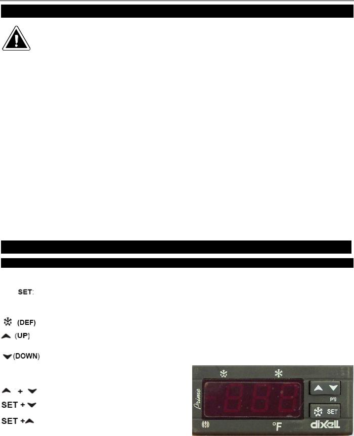
SOLID-STATE THERMOSTAT DESCRIPTIONS
1.FRONT PANEL COMMANDS
1.1 KEY FUNCTION
To display target set point; in programming mode, it selects a parameter or confirms an
operation.
To start a manual defrost
To view last alarm occurrence; in programming mode, it browses the parameter codes or increases the display value
To view last alarm occurrence; in programming mode, it browses the parameter codes or
decreases the display value
KEY COMBINATION
To lock & unlock the keyboard
To enter in programming mode
To return to the room temperature display
5
 Loading...