

Page 1

VMOD-2/VMOD-2D
VModular Industrial I/O Module
for VMEbus Applications
Manual ID 03139, Rev. Index 0200 of 12/10/97
Page 2

This page was intentionally left blank.
Man. ID 03139, Rev. Index 0200
Page 3

VMOD-2/VMOD-2D
Preface
Preface
Revision History ............................................................. 0-6
For Your Safety.............................................................. 0-5
Special Handling and Unpacking Instructions 0-5
HV Safety Instructions 0-6
Two Years Warranty ...................................................... 0-7
Table of Contents........................................................... 0-8
Warning!
The first index (PCB layout 00) of VMOD-2 was designed for
improved noise immunity (via multi-layer shielding) and as such
have insufficient clearance around the piggybacks I/O pins and the
50-way external interface connectors pins to ensure the 2.5kV
breakdown isolation specified by certain piggybacks. Use index 01
or higher for such applications, or take additional measures to be
taken to ensure syste m/user safety.
12/10/97
Page 0 - #Man. ID 03139, Rev. Index 0200
Page 4

VAR Product Name
R
EVISION HISTOR
Y
Manual/Product Title:
VMOD-2/VMOD-2D
Manual ID Number:
03139
Rev.
Index
Brief Description of Changes
PCB Index
Date of
Issue
Revision History
0100 Initial Issue 01 01 Feb. 1992
0101 Changes to Address Range in 2.4 01 01 July 1994
0200 Standard Preface, New Numbering System 01 01 Dec. 1997
Preface
This document contains proprietary information of
copied or transmitted by any means, passed to others, or stored in any retrieval system or
media, without the prior consent of
The information in this document is, to the best of our knowledge, entirely correct. However,
PEP Modular Computers
thereof, nor for any liability arising from the use or application of any circuit, product, or example shown in this document.
PEP Modular Computers reserve the right to change, modify, or improve this document or the
product described herein, as seen fit by
cannot accept liability for any inaccuracies, or the consequences
PEP Modular Computers
PEP Modular Computers
PEP Modular Computers
or its authorized agents.
without further notice.
. It may not be
12/10/97
Page 0 - #Man. ID 03139, Rev. Index 0200
Page 5

VAR Product Name
Preface
For your safety
PEP
This
can be drastically reduced by improper treatment during unpacking and installation. Therefore, in the interest of your own safety and of correct operation of your new PEP product,
please take care of the following guidelines:
product is carefully designed for a long, fault-free life. However, its life expectancy
Before installing your new
power mains. This applies also to installing piggybacks.
In order to maintain
in any way. Changes or mo difications to the device, which are not explicitly approved by
PEP Modular Computers
Support as a special handling instruction, will voi d your warranty.
This device should only be installed in or connected to systems that fulfill all necessary
technical and specific environmental requirements. This applies also to the operational
temperature range of the specific board version, which must not be exceeded. If batteries are present, their temperature re strictions must be taken into account.
In performing all necessary installation and application operations, please, follow only
the instructions supplied by the present manual.
Keep all the original packaging material for future storage or warranty shipments. If it is
necessary to store or ship the board, please, re-pack it in the original way.
PEP’s
PEP
product into a system, please, always switch off your
product warranty, please, do not alter or modify this product
and described in this manual or received from
PEP
Technical
Special Handling and Unpacking Instructions
Electronic boards are sensitive to static electricity. Therefore, care must be taken during all
handling operations and inspections wi th this produ ct, in order to ensure pro duct integrit y at all
times.
Do not handle this product out of its protective enclosure while it is not being worked
with, or unless it is otherwise protected.
Whenever possible, unpack or pack this product only at EOS/ESD safe work stations.
Where safe work stations are not guaranteed, it is important for the user to be electri-
cally discharged before touching the product with his/her hands or tools. This is most
easily done by touching a metal part of your system housing.
Particularly, observe standard anti-static precautions when changing piggybacks, ROM
devices, jumper settings etc. If the product contains batteries for RTC or memory backup, ensure that the board is not placed on conductive surfaces, including anti-static
plastics or sponges. They can cause short circuits and damage the batteries or tracks
on the board.
12/10/97
Page 0 - #Man. ID 03139, Rev. Index 0200
Page 6

VAR Product Name
Safety Instructions for High Voltages
This chapter of the safety instructions appli e s to HV appli ances (> 60 V) only.
Preface
Your new
to ensure the reknown electrical safety requirements. However, serious electrical shock hazards exist during all installation, repair and maintenance operations with this product. Therefore, always unplug the power cable to avoid exposure to hazardous voltage.
All operations on this device have to be carried out by sufficiently skilled personnel only.
PEP
product was developed and tested carefully to provide all features necessary
12/10/97
Page 0 - #Man. ID 03139, Rev. Index 0200
Page 7

VAR Product Name
Two Years Warranty
Preface
Preface
PEP Modular Computers
HARDWARE
be granted or implied by anyone on behalf of
expressed written consent of
PEP Modular Computers
manufacturing and material defects for a period of 24 consecutive months from the date of
purchase. This warranty is not transferable nor extendible to cover any other users or longterm storage of the product. It does not cover products which have been modified, altered or
repaired by any other party than
more, any product which has been, or is suspected of being damaged as a result of negligence, unproper use, incorrect handling, servicing or maintenance, or which has been
damaged as a result of excessive current/voltage or temperature, orwhich has had its serial
number(s), any other markings or parts thereof altered, defaced or removed will also be
excluded from this warranty.
If the customer’s eligibility for warranty has not been voided, in case of any claim, he may
return the product at the earliest possible convenience to the original place of purchase,
together with a copy of the original document of purchase, a full description of the application
the product is used on and a description of the defect. Pack the product in such a way as to
ensure safe transportation (see our safety instructions).
PEP
provides for repair or replacement of any part, assembly or sub-assembly at their own
discretion, or to refund the original cost of purchase, if appropriate. In the event of repair,
refunding or replacement of any part, the ownership of the removed or replaced parts reverts
PEP Modular Computers
to
guarantee to cover the repaired or replaced items, will be transferred to cover the new or
repaired items. Any extensions to the original guarantee are considered gestures of goodwill,
and will be defined in the “Repair Report” issued by
WARRANTY
grants the original purchaser of
as described in the following. However, no other warranties that may
PEP
PEP Modular Computers
warrants their own products, excluding software, to be exempt of
PEP Modular Computers
, and the remaining part of the original guarantee, or any new
PEP
products a
are valid unless the consumer has the
.
or their authorized agents. Further-
PEP
with the repaired or replaced item.
TWO YEARS LIMITED
PEP Modular Computers
rectly from any warranty claim, other than the above specified repair, replacement or refunding. Particularly, all claims for damage to any system or process in which the product was
employed, or any loss incurred as a result of the produc t not functi oning at any given time, are
excluded. The extent of
original purchase price of the item for which the claim exist.
PEP Modular Computers
respect to its products, reliability, fitness, quality, marketability or ability to fulfil any particular
application or purpose. As a result, the products are sold “as is,” and the responsibility to
ensure their suitabilit y for an y given t ask r emain s of the purch aser. I n no eve nt wil l
ble for direct, indirect or consequential damages resulting from the use of our hardware or
software products, or documentation, even if PEP were advised of the possibility of such
claims prior to the purchase of the product or during any period since the date of its purchase.
Please remember that no
make any modification or addition to the abovespecified terms, either verbally or in any other
form written or electronically trans mitted, without the company’s consent.
will not accept liability for any further claims resulting directly or indi-
PEP Modular Computers
issues no warranty or representation, either explicit or implicit, with
PEP Modular Computers
liability to the customer shall not exceed the
PEP
be lia-
employee, dealer or agent i s author ize d to
12/10/97
Page 0 - #Man. ID 03139, Rev. Index 0200
Page 8

VAR Product Name
g
g
g
g
gg
Chapter
Chapter
1. Introduction...............................................................1-1
1.1 Product Overview................................................. 1-1
1
1
Preface
1.2 Orderin
1.3 Glossary of Terms................................................ 1-2
1.4 Hazards................................................................ 1-2
1.5 VMOD-2 Specifications........................................ 1-3
1.6 VMOD-2 Board Overview .................................... 1-4
1.7 Advanta
PepCard 1-5
1.7 Advanta
PepCard 1-5
1.8 Functional Block Dia
1.9 Related Publications ............................................ 1-7
1.10Pi
Information............................................ 1-1
es and Features of the VMOD-2
es and Features of the VMOD-2
ram ................................... 1-6
yback Selection Assistance.......................... 1-7
Chapter
2. Functional Description..............................................2-1
2.1 VMOD-2 Address Map......................................... 2-1
2.2 VMEbus Interrupts ............................................... 2-3
2.3 External "Local" Reset Input .............................. 2-5
2.4 ID Byte ................................................................. 2-8
2.5 VMOD/VMOD-2 Connector Location s and
Pin-Outs............................................................... 2-9
12/10/97
2
Page 0 - #Man. ID 03139, Rev. Index 0200
Page 9

VAR Product Name
g
g
g
g
g
Preface
Chapter
3. Configuration............................................................3-1
3.1 Jumper Location s and Functions......................... 3-1
3.2 Fittin
Chapter
4. Installation .............. .. ... ................ ... ................. .. .......4-1
4.1 VMEbus Connection............. .. .. ........................... 4-1
4.2 Installin
4.2 IChronolo
4.4 Connectin
3
Piggybacks...... .. ... ................. .. ................. . 3-7
4
the VMOD-2.......................................... 4-1
ical Installation Procedure.................. 4-2
the External Devices......................... 4-3
4.5 Front Panel Functions.......................................... 4-4
4.6 Trouble-shootin
VMEbus System.................................................. 4-5
4.7 General Remarks on the Use of Your System..... 4-6
for VMOD-2/VMOD and
12/10/97
Page 0 - #Man. ID 03139, Rev. Index 0200
Page 10

VAR Product Name
Preface
Annex
System Configuration Record........................................ A-1
Annex
VMOD-2 Board Layout................................................... B-1
Annex
VMOD-2 Schematics ..................................................... C-1
A
B
C
12/10/97
Page 0 - #Man. ID 03139, Rev. Index 0200
Page 11

VMOD-2/VMOD-2D
Product Overview
Product Overview
1.1 Product Overview.................................................................. 1-1
1.2 Ordering Information............................................................ .. 1-1
1.3 Glossary of Terms................................................................. 1-2
1.4 Hazards................................................................................. 1-2
1.5 VMOD-2 Specifications......................................................... 1-3
1.6 VMOD-2 Board Overview...................................................... 1-4
1.7 Advantages and Features of the VMOD-2 PepCard............. 1-5
Chapter
1
1.7.1 Features of the VMOD-2 Module.................................. 1-5
1.7 Advantages and Features of the VMOD-2 PepCard............. 1-5
1.8 Functional Block Diagram ..................................................... 1-6
1.9 Related Publications.............................................................. 1-7
1.10 Piggyback Selection Assistance............................................ 1-7
1.10.1 VMOD/VMOD-2 Piggybacks Overview........................ 1-8
12/15/97
Page 1 - 1Man. ID 03139, Rev. Index 0200
Page 12
VMOD-2/VMOD-2D
Product
Description
Order No.
Product Overview
1. Introduction
1.1 Product Overview
VMOD-2 is a "User Configurable" Industrial I/O module with the ability to fit any two (identical
or different) standard sized VMOD piggybacks. Each fitted piggyback shares half of the front
panel's 50-way connector allowing a flat-ribbon cable to be easily routed to either one or two
end devices. The VMOD-2 may not only be used with all existing (VMOD) piggybacks, but will
also accept the future generation of enhanced piggybacks, which may use the additional signal lines only provided on the VMOD-2.
Upgrade paths/Compatibility. The original VMOD is no longer available and if ordered will
automatically be replaced with the new VMOD-2. The VMOD-2 can be used as a direct
replacement for any application using an older style VMOD. Full electro-mechanical compatibility (and acceptance of the existing piggyback int erfaces) is guaranteed.
The VMOD-2 may be used as a direct replacement for an y existing VMOD and will accept the
fitted piggybacks from that existing VMOD without any modification. (See also special note
below)
A VMOD may be used in place of the new VMOD-2 with the loss of some new features, and
then only with piggybacks developed up to the end of 1990. Any enhanced piggybacks which
need additional signals from the VMOD-2 will not work on the old VMOD. To identify which
piggybacks are only suit able f or use on the VMOD-2 loo k for a f our digit o rder number suc h as
the PB-BIT has. i.e. 5230-11. Any and all piggybacks with three digit numbers 523-xx, will
function with both VMOD and VMOD-2 modules alike.
1.2 Ordering Information
Table 1-1: VMOD-2 Ordering Information
VMOD-2 VMEbus industrial I/O interface module with
latching 50 pin front panel connector, but
without the additional on-board 50 pin
header.
VMOD-2 VMEbus industrial I/O interface module with
the 50 pin flat ribbon on-board header only.
(the 50-pin front panel connector is omitted)
5230-0
5230-1
12/15/97
Special Note! Caution!
VMOD-2 boards with an index 00 offe r increased inter-board shielding by
using tight-routed ground and V cc planes in their multi-layer layout. This
will compromise the 2.5 kV breakdow n isolation offered by many VMODpiggybacks. If the 2.5 kV fault isolation is important for the application,
Page 1 - 2Man. ID 03139, Rev. Index 0200
Page 13

VMOD-2/VMOD-2D
AB#
PBx
PCB
PSU
please use a VMOD-2 with a board index of 01 upwards since this will
have an increased galvanic isolation gap around the 50-way external
interface and 26-way piggyback I/O pin areas.
Product Overview
1.3 Glossary of Terms
This is a brief description of some of the abbreviations used throughout this manual.
Table 1-2: Abbreviations
Address Block number (used in some tables in this
manual to signify a 256 byte wide address block chosen out of a maximu m permis sible 32 ad dresse s)
Piggyback (where x is the location "A" or "B")
Printed Circuit Board
Power Supply Unit
1.4 Hazards
The VMOD-2 can be fitted with one or two piggybacks carrying voltages classed as dangerous (i.e. over 50V dc). These are usually powered by external devices and therefore are not
powered subject to the status of the VMEbus systems power switch. This can result in a
VMOD/VMOD-2 being removed from a powered-down rack with an external device still connected and presenting its voltage to the solder-side of both the VMOD/VMOD-2 and the back
of the respective piggyback. A typical example is the PB-REL an eight relay SPST switching
module, which can in certain circumstances present an unsuspecting user with up to 175V dc
when pulling out (or installing) a VMOD-2 with the external powered interface leads connected. (For continued fault isolation to 2. 5 kV use a VMOD-2 of index 01 or higher).
12/15/97
Page 1 - 3Man. ID 03139, Rev. Index 0200
Page 14
VMOD-2/VMOD-2D
Figure 1-1: VMOD-2 Hazard Example (PB-REL)
Product Overview
26-pin
ST 2
Connector
8 x SPDT
Relays
GAL &
Interface
Logic ICs
This end towards
front of VMOD
Caution!
enclosed area
carries your
externally
connected
voltages and
may present
shock hazar d
Caution!
When using Piggybacks w ith external interfaces or supplies carrying Voltages higher than 50V dc ensure that the solder pins on the rear side of
the PB-xxx and the VMOD to which it fits, are not acc essible (cannot be
accidently touched) during use. These pins can be under power all the
time the external interfaces are connected, when powered,
even when VMOD-2/VMEbus is no t powered!
12/15/97
Page 1 - 4Man. ID 03139, Rev. Index 0200
Page 15

VMOD-2/VMOD-2D
VMOD-2
Specification
1.5 VMOD-2 Specifications
Table 1-3: VMOD-2 Specifications
External Interface 50-way flat band cable connector (upper half and
VMEbus Interface A24:D8/16, A16:D8/16 Slave
VME Address Range Occupies 256 Bytes or 8 KBytes, A1....A11 to each
Interrupt Requester Single-level , IRQ 1-7. Jumper selectable. Two
Product Overview
lower half used by respective piggyback position)
only accessible via the addition of VMOD/VMOD-2
piggyback (s) to the desired interface standard
piggyback. Base Address jumper selectable.
lines for interrupt request, one per Piggyback. Interrupt vector generated by piggybacks, or by jumper
settings on VMOD-2.
External Reset Inputs Pins 25 and 26 of front-panel connector may be
used to connect a NC (Normally clo sed) push- button reset switc h, or fo r the crea tion of an "Emergency-Stop" loop, or for automatic detection of
disconnection of interface. This facility may be disabled via jumper setting.
Power Requirements +5V DC (±5%), 140 mA, excluding additional piggy-
backs demands
Temperature Range
- Operating
- Storage
Operating Humidity 5 - 95% (non-condensing)
Board Size Single-height Eurocar d 100 x 160 mm (4 x 61/4 ")
VMOD to Piggyback
Connectors (VME
side)
- 0° to +70°C (standard)
- -40° to +85°C (extended, subject to fitted piggy back/-s)
- -55° to +85°C
A triple-row (to/from VMOD's VME side) per pigg yback location. Providing Address, Data and necessary control line interfaces to selected PB type(s)
fitted.
12/15/97
Page 1 - 5Man. ID 03139, Rev. Index 0200
Page 16

VMOD-2/VMOD-2D
VMOD-2
Specification
Table 1-3: VMOD-2 Specifications
Product Overview
VMOD to Piggyback
Connectors (User
side)
VMEbus Connecto r DIN 41612 style C, 96-p in
Front Panel Width 4 TE (20.3 mm)(1 slot)
Front Panel Connec -
tor
Piggybacks General See respective piggyback's manual for exact speci-
Piggyback Size Width: 48 mm(1 7/8 inches)
A double-row (to/from user I/O side) set of connectors per piggyback location. These connectors are
galvanically isolated for 2.5 kV (not on index 00
however) from the rest of the VMOD-2 circuits and
are selected to their respective function according
to actual piggyback(s) fitted.
50-pin male ribb on cable header with ret ain/ejec t
latches. Alternatively, no front connector, but a 50pin on-board header (without retain/eject latches
where interfaces are to be kept internal to rack/
equipment.
fications.
Length: 100 mm(3 15/16 inches)
Depth: 12 mm (1/2 inch)
Mechanical/Electrical Interface
Temperature Range:
- Operatin g
- Storage
Held by either Two sets of twin row header pins, or
a triple-row and double-row set of headers, providing all necessary communication paths and a
mechanical mounting method.
- 0° to +70° C (standard)
- -40° to +85° (extended, for some piggybacks)
- typically -55° to +85°C
12/15/97
Page 1 - 6Man. ID 03139, Rev. Index 0200
Page 17
VMOD-2/VMOD-2D
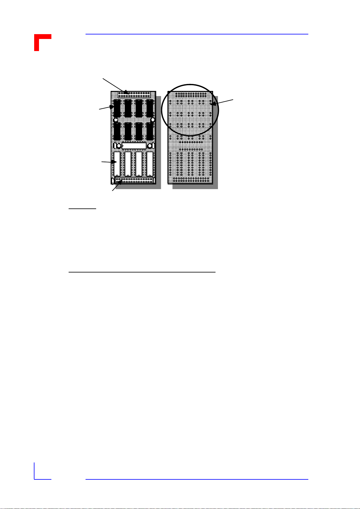
1.6 VMOD-2 Board Overview
Figure 1-2: VMOD-2 Board Overview
Product Overview
Loc al Rese t
Enable/Disable
Jum pe r (B20)
50-way front
panel connecto r
— or —
26-way, 2-row
pig gyback s oc ket
Pig gyback A
Up per Loc a ti on
on VM O D -2
Pig gyback B
Lower Location
on VM O D -2
50 -way on-
boar d h eade r
VM Ebu s interface
logic in S MD device s
30/45-wa y 2/3-row
pig gyback s oc ket
Jum pers
B01
B19
96-way VME bus
c onn ec tor (P1, J1)
The VMOD-2 is a simple low-cost product designed for maximum flexibility while keeping the
single-height, single-slot modular concept of the PepCard. To ensure user/system security
against fault conditions is maintained with and when using opto-isolated piggybacks, the
VMOD-2 has a large area of unpopulated board space under the front half of both piggyback
locations. This unused area is part of the VMOD-2's Galvanic isolation (see special note on
page 1-1) and no additional wiring should be routed to/from component s in the rear-most area
of the VMOD-2 and the component groups (connectors) at the front of the VMOD-2. A "localReset" logic line is however routed to the three-p in j umper near the 50- pin fr ont pane l conne ctor, but this follows distancing and opto-isolation rules to ensure that the galvanic capability of
the opto-isolated piggybacks is not compromised.
The VMOD-2 is shown above with both the 50-way front panel connector and the 50-way onboard header. It can only be ordered with one or the other. Further the VMOD-2 is shown with
the two piggyback locations occupied, which is how the majority of users employ their
VMOD's, but is delivered without any piggybacks, these items being added to the above illustration to help see where the connectors and piggybacks are to be found /used.
Each of the two piggybacks are fitted so their 26-way connector pins fit into the correspondi ng
26-way socket-holes provided for each piggyback location. The rear connectors pins will then
fit into the correct rows of the 30/45-way sockets regardless of whether the piggyback has a
30-pin or 15-pin connector.
All the jumpers, with the exception of B20 (local reset), are to be found at the back end of the
VMOD-2 in several small groups. Jumper B01 is an "L" shaped group of three-pins nearest
the top edge of the board, and the rest are consecutively numbered progressing down the
VMOD-2 until the last (Jumper B19) is reached nearest the bottom of the board. The function
12/15/97
Page 1 - 7Man. ID 03139, Rev. Index 0200
Page 18

VMOD-2/VMOD-2D
of these jumpers, and a detailed illustration of their locations and pin-numbering, are to be
found in chapter 3 of this manual.
The remaining components on this simple low-cost industrial base board are in CMOS SMD
logic and GALs to ensure reduced power consumption/thermal generation over it's predecessor.
Product Overview
1.7 Advantages and Features of the VMOD-2 PepCard
The VMOD-2 is an improved version of the original VMOD, which was designed with a major
objective in mind: to provide a low cost and easy to implement user configurable I/O interface
for industrial interface applications and/or space-savings in many different customer applications.
This result is a maximized choice of design flexibility. The VMOD-2 provides a very costeffective solution, with quick and easy implementat ion, and fu ll compatibil ity with the ex tensive
range of existing VMOD-piggybacks and the ability to accept the planed "enhanced" piggybacks of the second generation.
With the flexibility offered by the VMOD-2 and the exi sting range of indust rial I/O modules, you
are able to configure many complex and usually very intense interfaces, in a very quick and
compact way. This may be especially important when needing to add interfaces to an already
existing system, or where when using other products several additional slots or a larger rack/
sub-frames or additional power supplies/cooling, were needed/used with their financial overhead.
Now with the VMOD-2 you may replace several of these existing cards, or external interface
boxes, with a single VMOD-2, fitted with two piggybacks containing the desired interfaces,
and also offering the added feature of a local res et input.
1.7.1Features of the VMOD-2 Module
Features of the VMOD-2 are:
* Widest possible range of base address selection to allow up to thirty-two VMOD-2's to
be used in any one system. (Prev iou sly onl y eight origi nal VMOD's coul d be fi tt ed due to
their fixed base addresses).
* Each piggyback location now supports 11 address lines. (A1...A11 to each piggyback).
* Each piggyback location now has 8/16-bit Databus lines. (D0..D15 to each piggyback).
* Galvanic Isolation between each interface and to the VMOD-2's VMEbus circuitry
depending upon the piggybacks fitted.
* External Reset facility, can be used to cause "local-reset" of the VMOD-2's piggybacks.
* Two Individually configurable piggyback locations, with board ID byte for remote (soft-
ware) configuration identity checking.
* Compact size, VMOD-2 plus two piggybacks containing your chosen interface circuitry,
are all contained within standard single-height, single-slot PepCard dimensions. Choice
of interface connector options, so where needed the connection method can be kept
internal, i.e. via a 50-pin on-board connector.
* Easy maintenance (i.e. swap-and-test, reduce service down-time)
12/15/97
Page 1 - 8Man. ID 03139, Rev. Index 0200
Page 19

VMOD-2/VMOD-2D
Hardware Features:
* Full electro/mechanical compatibility with the existing VMOD piggybacks and with the
very latest VMOD-2 enhanced piggybacks.
* All necessary VMEbus lines are made available to each of the piggybacks.
* 2.5 kV Galvanic VME to external isolation (not on index 00 boards), and PB to PB inter-
faces supporting opto-isolated piggybacks and the opto-isolated external "local" reset
input circuits.
* Extended temperature ver sions of bot h the VMOD-2 and many of the currentl y availab le
piggybacks, allowing combinations suitable for harsh industrial environments to be con-
figured.
Product Overview
12/15/97
Page 1 - 9Man. ID 03139, Rev. Index 0200
Page 20
VMOD-2/VMOD-2D
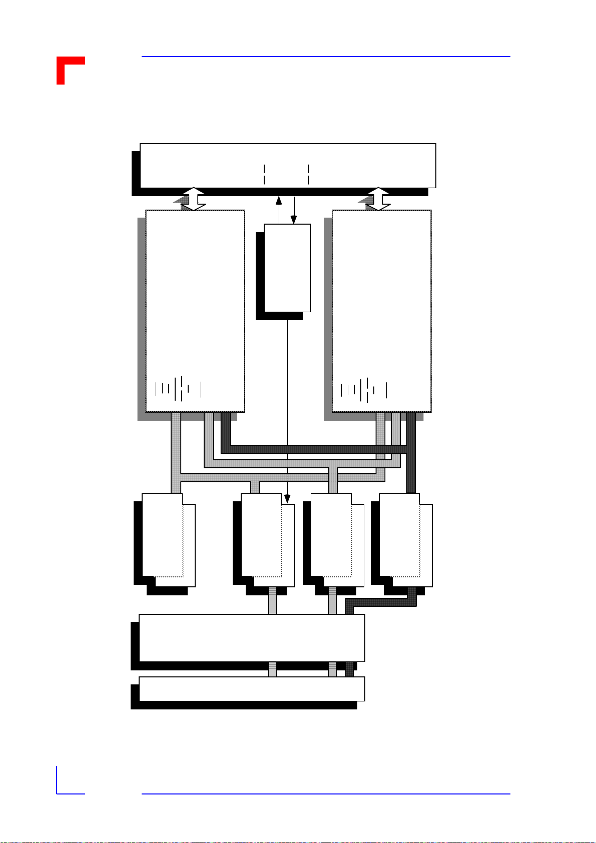
1.8 Functional Block Diagram of the VMOD-2
Figure 1-3: Functional Block Diagram
50-way E xternal Interface(s)
Pi ns
25 & 26
Piggyback
F itte d
Acco rdin g
Type
Use r
I/O
To
Disable Jumper
In put Log ic &
Pins 27...50 for Upper Piggyback Pins 01...24 for Low er Piggyback
Extern a l Rese t
Product Overview
Piggyback
F itte d
Acco rdi ng
Type
Use r
I/O
To
Must be ord ered
an d fitted
UDTACK1
INTA1
CS1
INT 1
Local/PB
Control
Logic
(Lower Location)
Op ti on a l Ex tra
IDS 0 / ID S1
IAS
Control
Piggyback "B"
PB I. D . dat a
ID 0...15
IA 1...11
RESET
CLK
Address
Data
In terrupt Control
IRQ* Driver
Logic and
VMEbus
Local Reset
I/O Control
Logic
Must be ord ered
an d fitted
UDTACK0
INTA0
INT 0
CS0
Dec odi ng and
P iggyba ck Select
Address
(Upper Location)
Op ti on a l Ex tra
IDS 0 / ID S1
IAS
Piggyback "A"
ID 0...15
PB I. D . dat a
IA 1...11
RESET
CLK
Driver
Data Latch
Data
12/15/97
Including...
IACK*
DS1*
IRQ1*. . .7*
IA CKOUT*
LWORD*
IACKIN*
AM0...5
SYSRESET*
WRITE*
DS0*
AS*
Co ntro l
SYSCLK*
96-way VMEbus Interface Conne ctor
Ad d ress
Data
A24/A16: D16/D8
Sla ve VM Ebus
Interface
Page 1 - 10Man. ID 03139, Rev. Index 0200
Page 21

VMOD-2/VMOD-2D
Product Overview
1.9 Related Publications
For more information regarding the VMEbus, please refer to:
* The VMEbus Specification, Revision C.1.
For details regarding the VMOD-piggybacks (or VMOD-2-piggybacks) , please refer to the
respective products User's Manual.
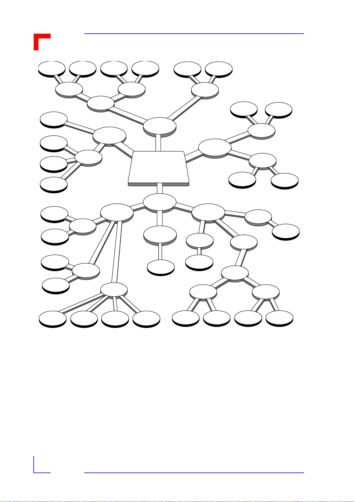
1.10Piggyback Selection Assistance
As there are so many different types of piggyback available for the VMOD-2, and many offer
different options such as common ground or Vcc for their inputs, etc. the following selection
help chart has been provided. It may be used in conjunction with the piggyback overview table
on the next page. The prototyping piggyback is not shown in this figure.
All grey edged "coins" are decisions or group titles, all black edged coins are actual product
names and order numbers.
12/15/97
Page 1 - 11Man. ID 03139, Rev. Index 0200
Page 22
VMOD-2/VMOD-2D
Figure 1-4: Piggyback Selection Chart
PB-DAC
fo r 0 -10 V
523-11
PB-DAC
fo r 0 - 8 . 1 92 V
523-11/1
PB-DAC2
for 4-20 mA
523-17
PB-DAC2
for 0-20 mA
523-17/1
ADC for
Voltage
523-28
Product Overview
ADC for
Curren t
523-28/1
8 x SPDT
8 Re lays
PB -R EL
523-26
5V
PB-STP
523-22/ 1
12V
PB-STP
523-22/ 2
24V
PB-STP
523-22
PB- CI O 20ch.
Change of State
523-19
PB- CI O 18ch.
Change of State
523-19/1
PB-DIN
for 5V (TT L )
523-14
PB- D IN2
for 12V-60V dc
523-24
DAC for
Voltage
Stepper
Moto r
Control
Change of
Stat e
Digi tal In
D to A
Converter
Industr ial
Control and
Swit c hing
In put
Counter
input
DAC2 for
Curren t
VMOD-2 piggyback
location (one of t wo) for
which an appropriate
Piggyback is sought
Analog
Digital
Output
PB-DOUT
for 5 -80V dc
523-25
A to D
Converter
Communications
I/O
(Select Volt age)
5V dc (TTL)
PB-DIO
CVcc in/CG ou t
523-13/ 1
PB-DIO2
for Cmn
Vcc In
PB -B IT
at 12 MHz
523 0 -1 1
PB -S IO4
non-isolated
523-15
Select
common mo d e
24V dc
BITBUS™
Cont roller
Serial I/O
4 x RS232C
5 - 80V dc
PB-DIO3
for Cmn
Gnd In
PB -B IT
at 16.67 MHz
5230-11/1
PB -S IO4
opt o-is o late d
523-15/1
PB- D IO4
C.G in /OCCE
523-27
PB-CNT
for 5V inputs
523-12/ 1
PB-CNT
fo r 1 2 V in pu t s
523-12/ 2
PB-CNT
fo r 1 5 V in pu t s
523-12/ 3
PB-CNT
fo r 2 4 V in pu t s
523-12
PB- D IO2
for Cmn Gnd out
523-16
PB- D IO2
fo r C mn Vc c o u t
523-16/ 1
PB- D IO3
for Cmn Gnd out
523-23
PB- D IO3
fo r C mn Vc c o u t
523-23/ 1
1.10.1VMOD/VMOD-2 Piggybacks Overview
Your VMOD-2 can accept any two piggybacks from those listed in the following table. Some
of the piggybacks have several different versions to allow their precise adaptation to your target application. i.e. The PB-DIO2 is av ailabl e with i t's outpu ts in a common gr ound o r common
Vcc mode. The differences are sh own by ital ics, braces and bracket s showing what char acte r-
12/15/97
Page 1 - 12Man. ID 03139, Rev. Index 0200
Page 23

VMOD-2/VMOD-2D
PB-Name
Brief
Description
Ch. @ V In
Ch. @ V
Out
Order #
istic is different in each order number type. The body text (normal) applies to all versions of
that piggyback type.
Table 1-4: Piggyback Overview
Product Overview
PB-DIO 20 Ch. Digi-
tal I/O with
68230 and
24-bit timer
PB-DIO2 20 Ch. Digi-
tal I/O with
68230 and
24-bit timer
PB-DIO3 20 Ch. Digi-
tal I/O with
68230 and
24-bit timer
PB-DIO4 16 Ch. High
Voltage Digital I/O
PB-DIN 20 Ch. Digi-
tal Input
68230 and
24-bit timer
10 ch. at 5V
/10mA opto,
Cmn Vcc
10 ch. 24V /
5mA opto,
Cmn Vcc
10 ch. 24V /
5mA opto,
Cmn Gnd
8 ch.12 to
80V / 5mA
opto CG in
pairs
20 ch. 24V
(5V) 10mA
opto CV
10 ch. at 5V/
10mA opto,
Cmn Ground
10 ch. 24V/
100mA opto,
CG (CV)
10 ch. 24V/
100mA opto,
CG (CV)
8 ch 5 to
80V/500mA
opto OC CE
in pairs
- 523-14
523-13/1
523-16
(523-16/1)
523-23
(523-23/1)
523-27
(523-14/1)
PB-DIN2 1 2 Ch. Hi-V
Digital Input
PB-DOUT 12 Ch. High
Voltage Digital Output
PB-CIO 20 Ch.
"Change of
State"
Z8536
Inputs
12 individual ch.s 12
to 60V 5mA
- 12 individ-
20 (18) CV
ch.s opto
24V/7.5mA
-523-24
ual ch.s 5 to
80V/500mA
(2 independant ch.
24V/5mA
opto)
523-25
523-19
(523-19/1)
12/15/97
Page 1 - 13Man. ID 03139, Rev. Index 0200
Page 24

VMOD-2/VMOD-2D
PB-Name
Brief
Description
Ch. @ V In
Ch. @ V
Out
Order #
Table 1-4: Piggyback Overview
Product Overview
PB-CNT 2x32-bit or
4x16-bit
Counter, @
500 kHz
max. input
speeds.
PB-SIO4 Quad Serial
I/O 68681
RS232 +
RTS and
CTS
PB-STP Single Axis
multi-mode
Stepper
Motor Controller.
PB-REL Eight SPDT
Relays
2/4 opto-isolated
counter
inputs, 24V/
5mA (5V/
10mA)
[12V] {15V}
4 x RS232, non-opto (optoisolated)
6 control
lines @
24V (5V )
[12V ] /
11mA optoisolated
- 8 x galv.-
- 523-12
10 lines / 1
Axis 24V
(5V) [12V]
8mA optoisolated
isolated
(523-12/1)
[523-12/2]
{523-12/3}
523-15
(523-15/1)
523-22
(523-22/1)
[523-22/2]
523-26
PB-DAC 4 ch 12-bit D
to A Converter
(10µs )
PB-DAC2 4 ch 12-bit D
to A Converter
(10µs )
PB-ADC 4 ch 12-bit D
to A Converter
(10µs )
PB-ADC-2 8 ch 10-bit A
to D Converter
(16µs)
-4ch. 010V±10V
(0-
8.192V±8.1
92V)
- 4ch. 4-20
mA (0-20
mA)
8 ch. 010V±10V
8 ch. 0-20
mA
- 523-28
523-11
(523-11/1)
523-17
(523-17/1)
523-28/1
12/15/97
Page 1 - 14Man. ID 03139, Rev. Index 0200
Page 25

VMOD-2/VMOD-2D
PB-Name
Brief
Description
Ch. @ V In
Ch. @ V
Out
Order #
Table 1-4: Piggyback Overview
Product Overview
PB-BIT BITBUS™
Communications Controller
PB-PRM Prototyping User definable I/O accord-
CG = Common Ground, CV = Common Vcc, opto = optoisolated, and OC CE =
open colector-common emitter.
* = PB-BIT is not suited for use with the original VMOD. BITBUS is a registered
trademark of the Intel corporation.
80C152A. 12 (16.67)
MHz. (2.4 Mbaud Sync.)
1.5 Mbaud self-clocked. 2 x
1 KByte FIFO
ing to your own design
5230-11*
(5230-11/1)*
523-18
12/15/97
Page 1 - 15Man. ID 03139, Rev. Index 0200
Page 26

This page was intentionally left blank.
Man. ID 03139, Rev. Index 0200
Page 27

VMOD-2/VMOD-2D
Functional Description
Functional Description
2.1 VMOD-2 Address Map.......................................................... 2-1
2.1.1 Selection of the Address Block Widths......................... 2-2
2.1.2 Address Range of the VMOD-2.................................... 2-2
2.2 VMEbus Interrupts................................................................. 2-3
2.2.1 Interrupt Generation on the VMOD-2............................ 2-3
2.2.2 Interrupt Level Setting................................................... 2-3
2.2.3 Interrupt Vector Options................................................ 2-3
Chapter
2
2.2.4 Interrupt Vector Setting................................................. 2-4
2.2.5 Interrupt Vector Setting Examples................................ 2-4
2.3 External "Local" Reset Input ................................................ 2-5
2.4 ID Byte................................................. .... ..... ......................... 2-8
2.5 VMOD/VMOD-2 Connector Locations and Pin-Outs............. 2-9
2.5.1 VMOD-2 (VMOD/VME End) Piggyback Connector
BU1/0.................. ..... ............................ ..... .... ..... ......... 2-10
2.5.2 VMOD-2 External Interface Connectors BU2a and
BU2b................... ..... ............................ ..... .... ..... ......... 2-11
2.5.3 Pin Outs of the VMOD Front Panel Connector with Two
VMOD-2s............................................. ..... .... ..... ......... 2-13
12/15/97
Page 2 - 1Man. ID 03139, Rev. Index 0200
Page 28

VMOD-2/VMOD-2D
Functional Description
2. Functional Description
The VMOD-2 is a very simple and compact Modular Base-board accepting any two VMODPiggyback sub-modules for user-configurable I/O in any VMEbus system. It is better suited for
use in conjunction with other VMOD-2's in a VMEbus system than the original VMOD, which
only had eight different ba se addresses. This cha pter will descr ibe the " physic al" in ter faces of
the VMOD-2, and the function of the external "local" reset interfaces.
Although this manual contains references to some VMOD piggybacks, you are asked to refer
to the piggyback's own user manuals for comprehensive and up to date information regarding
the individual piggyback products.
The VMOD-2 is designed to function as a slave module (any slot other than slot 1) in any 3U
or 6U VMEbus system. in 6U (double-height) systems it is fitted in the upper backplane connector (P1, J1).
2.1 VMOD-2 Address Map
The VMOD-2 is addressed by setting appropriate jumpers for each selectable Address-line
and/or the setting of an address modifier jumper (B03) to specify the desired addressing
mode. A further jumper B16 can be set to provide increased address block widths when using
the VMOD-2 with newer piggybacks using the additional address lines A7...A11. The first piggyback (upper location) is always available at the base address and the second piggyback
(lower location) is available at base address plus either offset $80/$81 or $1000/$1001, subject to selected address block widths.
All existing "VMOD" (523-xx) piggybacks use the address l ines A1.. .A6. Any new 5230-xx piggybacks (VMOD-2 only types) use not only the address lines A1...A6, but als o A7...A11 which
are provided on the VMOD-2 only.
Remember!
Any existing and/or new piggybacks with a "523-" order number, can be
used on either an original VMOD or a VMOD-2, and when used on a
VMOD-2 may be used in either 256 Byte or 8 KB yte address block widths.
Any new piggybacks with a "5230-" order number (only suitable for
VMOD-2 use) with the address block width of 8 KBytes. A VMOD-2 can
have a mix of old and new piggybacks fitted provided the address block
width is set for the increased 8 K Byte addressing mode, i.e. jumper B16
must be set.
Via the address offsets, the user can address specific piggyback devices (i.e. SCCs) by writing to the selected VMOD-2's base address plus an offset of the appropriate value (see specific piggyback user's manual).
Example of offsets where two PB-RELs are fitted to VMOD-2.
12/15/97
Page 2 - 2Man. ID 03139, Rev. Index 0200
Page 29

VMOD-2/VMOD-2D
Configuration for base add ress rang e $FE2400 to $FE24F F
Addressing piggyback (i.e. PB-REL) fitted in location A (the upper position on VMOD-2)
Functional Description
• VMOD-2 BASE ADDRESS+$41= PB-REL's ID Vector (read only)
• VMOD-2 BASE ADDRESS+$01= PB-REL's 8-bit output port Register
(read/write)
Addressing piggyback (i.e. PB-REL) fitted in location B (the lower position on VMOD-2)
• VMOD-2 BASE ADDRESS+$C1/$1041* = PB-REL's ID Vector (read
only)
• VMOD-2 BASE ADDRESS+$81/$1001* = PB-REL's 8-bit output port
Register (read/write)
* Actual offset for lower piggyback is subject to the setting of jumper B16 and could be $10xx
if a 5230-xx piggyback is fitt ed in to the up per pi ggyb ack locat ion, and jumper B16 is set . I. e. 8
KByte address width is required.
Table 2-1: Default Setting of the VMOD-2 Base Address
VMOD-2 Jumpers B02 B12 B13 B14 B15 B16 Base Address
Default Settings Set Set Open Set Set Open $FE2400
Address Lines A15 A14 A13 A12 A11 in
256
Byte
block
A jumper set results in the related address line being assigned a logical low (0) function.
2.1.1Selection of Address Block Widths
As mentioned in the preceding section, an important aspect regarding the use of the VMOD-2
is the option of block size selection, which must be taken into consideration when using the
VMOD-2 in certain configurations and/or applications.
When using the VMOD-2 to replace an existing VMOD (as a one-to-one direct replacement),
the VMOD-2 should be set to the narrower address range of 256 Bytes by opening the jumper
B16. This ensures that the VMOD-2 presents an address width of only 256 Bytes identical to
the old VMOD, and uses offsets of $01 and $80 for the two piggyback locations.
No new "5230-xx" piggybacks should be added to the VMOD-2 when used as a replacement
for an older VMOD since when jumper B16 is open the enhanced (5230-xx) piggybacks will
not have the use of additional address lines A7...A11 and will not therefore function correctly.
Where using existing piggybacks and a VMOD-2 to substitute an older style VMOD, we rec-
12/15/97
Page 2 - 3Man. ID 03139, Rev. Index 0200
Page 30

VMOD-2/VMOD-2D
Jumper B16 Setting
Set
Open
ommend the jumper B16 is removed, which will ensure that your software will address both
piggybacks correctly without any need of modification.
Functional Description
Table 2-2:Address Block Widths According to Jumper B16 Setting
VMOD-2's Address Block Width 8 KByte 256 Byte
Upper Piggybacks add ress offset $00/$01 $00/$01
Lower Piggybacks add ress offset $1000/$100 1 $80/$81
Address lines available t o piggy-
backs
Special note!
The user's manuals for various piggybacks currently in existence, will
continue to give details of their address offsets based on the 256 Byte
address block spacing as described above. You can of course use the
new 8 KByte spacing with all "523-xx" piggybacks, by simply increasing
the offset from $80/$81 to $1000/$1001 for p iggyback location B .
A1.....A11 A1....A6
2.1.2Address Range of the VMOD-2
Using the address widths given before, you are able to select from either thirty-two 256 Byte
wide addresses, or from eight 8 KByte wide addresses,. i.e. your system can have 32 or eight
VMOD-2s fitted subject to your address configurations. The address selection is acheived by
decoding the state of five jumpers, B2, B12, B13, B14 a nd B15. Where a jumper Set returns a
logical 0 for the respective address line and a jumper Open returns a logical 1 for the respective address line.
A full listing with all address setting permutations is given in section 3.1.6.
2.2 VMEbus Interrupts
2.2.1Interrupt Generation on the VMOD-2
Each piggyback on the VMOD-2 is able to request/generate interrupts between levels 1 to 7.
However the VMOD-2 will only be set for one level of interrupt for use on the VMEbus.
For each request from pigg ybacks , I NT0* for pi ggyback lo cati on "A " and I NT1* f or " B", t here is
an acknowledge signal, INTA0* and INTA1* respectively. If two simultaneous interrupts are
detected, the one which is first will disable any handling of the other until its been dealt with
itself.
2.2.2Interrupt Level Setting
As mentioned above the user can set his VMOD-2 to use any IRQ level from 1 to 7 as appropriate to his VMEbus systems application. The selection of these levels is subject to the set-
12/15/97
Page 2 - 4Man. ID 03139, Rev. Index 0200
Page 31

VMOD-2/VMOD-2D
Dumb
Dumb
Dumb
Dumb
Dumb
Dumb
Int Fixed
Int Fixed
Int Progr
Int Progr
Int Progr
Int Progr
Int Progr
Int Progr
Int Progr
Int Progr
ting of three jumpers B17, B18 and B19, where when all three are set the IRQ from the
VMOD-2 is disabled. See section 3.1 (jumper configuration) for detailed settings.
Functional Description
2.2.3Interrupt Vector Options
The user can select between several different ways to use his VMOD-2's Interrupt Vectors as
the VMOD-2 is provided with a jumper (B1) with three different possibilities. See section 3.1
(jumper configuration) for detailed settings.
1). Vector can be generated by either or both piggybacks, if these pig gybacks are intel ligent
enough. Most are.
2). Vector can be generated by the VMOD-2, using preset jumper coding, where non-intelli gent piggybacks are being fitted. In thi s mode a furt her opt ion to as sig n both piggyb acks
the same vector is provided by the setting of a three-pin jumper B11.
3). Vector can be generated by the lower piggyback ("B") and derived from jumper settings
on the VMOD-2 for a non-intelligent pi ggyba ck fitted into the up per pi ggyba ck ("A") loc ation.
The features of some piggybacks you may wish to use on your VMOD-2 are:
Table 4-3: Possible Piggybacks for VMOD-2
PB-DAC D to A converter piggyback
PB-DAC-2 D to A converter piggyback
PB-DIN2 Digital input piggyback
PB-DIO4 Digital I/O piggyback
PB-DOUT Digital output piggyback
PB-REL Octo-Relay piggyback
PB-ADC A to D converter piggyback
PB-CNT Counter piggyback
PB-BIT BITBUS™ communications piggy-
back
PB-CIO Counter/I/O piggyback
PB-DIN Digital Input piggyback
PB-DIO Digital I/O piggyback
PB-DIO-2 Digital I/O piggyback
12/15/97
PB-DIO-3 Digital I/O piggyback
PB-SIO4 Quad serial piggyback
PB-STP Digital I/O piggyback
Dumb = no on-piggyback vector generation ability .
Page 2 - 5Man. ID 03139, Rev. Index 0200
Page 32

VMOD-2/VMOD-2D
Interrupt Vector Bit
Jumper Numbers
Example Setting # 1
Upper PBs Vector
Lower PBs Vecto r
Example Setting # 2
Upper PBs Vector
Lower PBs Vecto r
Example Setting # 3
Upper PBs Vector
Lower PBs Vecto r
Int Fixed = Vector is pre-fixed on-board the piggyback
Int Progr = programmable vector on piggyback
Functional Description
2.2.4Interrupt Vector Setting
As described before, the user can set his VMOD-2's Interrupt Vectors as appropriate to his
VMOD-2/Piggyback configurations needs. The selection of these vectors is subject to the
binary code of bits D0.. .D7 as derived by the setting of jumpers B11 to B4 respective ly. B11 is
a three-pin type and can provide an identical or different vector for the two piggybacks. Three
examples are given below where jumper B1 must be set to 1-2 to use these vectors.
Table 2-4: Interrupt Vector Selection
D7 D6 D5 D4 D3 D2 D1 D0
B04 B05 B06 B07 B08 B09 B10 B11
Open Open Open Open Set Open Set 1-3*
F4
F5
Open Open Open Open Set Open Set 1-2*
F4
F4
Open Open Open Open Set Open Set Open
F5
F5
* = If jumper B11 is set for 1-3, D0 will return a "0" for piggyback "A" and a "1" for
piggyback "B".
When jumper B11 is set to 1-2 the vector of both piggyback locations "A" and "B"
will be the same (so D0 = 0).
When jumper B11 is open the vector of both piggyback locations "A" and "B" will
also be the same (but D0 = 1).
12/15/97
Page 2 - 6Man. ID 03139, Rev. Index 0200
Page 33

VMOD-2/VMOD-2D
#
Configuration
Vector
Modes
B1 Settings
B4...B11
Settings
Functional Description
2.2.5Interrupt Vector Setting Examples
The following examples are provided to help VMOD-2 users to quickly understand when and
how to set his VMOD-2's Interrupt Vectors as appropriate to his VMOD-2/Piggyback configurations needs.
Table 2-5: Interrupt Vector Configuration Examples
1). Two "intelligent" pi ggyback s
(both able to generate interrupt vectors) are fitted to the
VMOD-2 to use their own generated vecto rs.
2). Two "Dumb" piggybacks
(both unable to gener ate
interrupt vectors) are fitted to
the VMOD-2 and ne ed
VMOD-2's set vectors.
3). One "intelligent" and one
"Dumb" piggyb ack are to be
fitted to the VMOD-2 and the
user wants th e intell igent pi ggyback to use it's on-board
"Intelligent" vector generation
in combination with "Dumb"
jumper coding.
Use Piggyback Generated Vectors
Use VMOD-2
Jumper set
Vectors
Use the
"Dumb" piggyback in
upper location, and fit
the "intelligent" one in
lower location.
2.3 External "Local" Reset Input
Jumper B1 is
left open.
B1 is to be
set to 1-2.
B1 is to be
set to brid ge
pins 1-3.
Jumpers
B4...B11 ar e not
decoded and can
be left in any setting.
Jumpers
B4...B11 are set
for appropriate
byte coding.
Jumpers
B4...B11 are set
for desired vector
code to be
assigned when
piggyback "A"
makes an IRQ.
A new feature of the VMOD-2 is the ability to cause a "local" reset to the on-board pi ggybacks
from two (previously unused) pins on the front panel connector. These pins accept external
voltages between +5V min. and +48V max, across each VMOD-2.
Set jumper B20 to 1-2 if an external reset facility is n ot required.
The principals of the local reset input circuit are, that an opto-coupler is monitored for an
external presence of current i n through pin 26 and out to ground via pin 25 of the 50-way connector. If the flow of current is interrupted at any time, e.g. by disconnection of connectors,
pressing a stop button, etc., the "local" reset is act ivated.
This facility may be enabled by setting the three- pin B20 jumper (li nking jumper pins 1-3). Otherwise the VMOD-2 is delivered with this jumper set to 1-2, which is particularly important
when using the VMOD-2 to replace an existing VMOD and not wanting to modify cables.
12/15/97
Page 2 - 7Man. ID 03139, Rev. Index 0200
Page 34

VMOD-2/VMOD-2D
Functional Description
The External Reset is limited to the VMOD-2 and it's piggybacks, and will not reset the VMEbus unless your application software demands it to. I.e. via the polling of an output register to
detect a "reset" state.
Special note!
There can be occasions when spurious interrupts are caused with the use
of the "local" reset facility.
This can happen when a VMOD-2 IR Q is cleared by the local re set before
the VMEbus system h as had a chance to clear the interrupt itself.
The two-pins (25 and 26) of the 50-way front panel connector, can be used to detect the following external events;
Figure 2-1: External Reset Connection — Example 1
1).
VM OD
2
Bre a ki ng ei th er of t hese connectors
causes a local reset to the VMOD-2
Detect breaking of any intermediate connectors between VMOD -2 and exte rnal
device.
Machin e
Vcc
Upper
pig gybac k
0V or
Lower
pig gybac k
In this kind of mode their two wires are
joined to Vcc and Gnd at the furth est end.
Gnd
12/15/97
Page 2 - 8Man. ID 03139, Rev. Index 0200
Page 35

VMOD-2/VMOD-2D
Figure 2-2: External Reset Connection — Example 2
Functional Description
2).
VM OD
2
Sa fety cage door holding N O switch
clo sed . Openin g do o r ( switch) will
cause a local reset to the V MO D-2
Detect the opening of safety-cage doors of
any external device under VMO D-2's control.
Machin e
Vcc
Upper
pig gybac k
0V or
Lower
pig gybac k
The two wires are at tached through "NO"
terminals of the switch, which automatically
opens when the doo r becomes "Uns afe"
(opened).
Gnd
12/15/97
Page 2 - 9Man. ID 03139, Rev. Index 0200
Page 36

VMOD-2/VMOD-2D
Figure 2-3: External Reset Connection — Example 3
Functional Description
3).
VM OD
2
Pr essin g eith er of these but t o n s w ill
cause a local reset to the V MO D-2
Machine
Upper
pig gybac k
Lower
pig gybac k
Vcc
0V or
Gnd
Pseudo "emergen cy stop" bu tton chain for
manual intervent ion, i.e. during mot or control applicatio n develop ment.
In this kind of mo de the ir two w ires bein g
daisy chained thr ough sever al NC
switches, and joined to Vcc and Gnd at the
most distant end.
12/15/97
Page 2 - 10Man. ID 03139, Rev. Index 0200
Page 37

VMOD-2/VMOD-2D
Figure 2-4: External Reset Connection — Example 4
Functional Description
4).
Machine #2
Pin-26
Pin-25
Upper
pig gybac k
Vcc
Reset
Logic
Machine #1
0V or
VM OD
2
I f mach in e 2's reset lo g ic turns reset loop su pply
off, or bu tton p re ssed bo t h V M OD- 2s will reset
VM OD
2
Lower
pig gybac k
Gnd
To synchronize the reset of two (or mo re)
VMOD-2s (see voltage notes on next
page).
The two wires ar e daisied throug h two
VMOD-2s and the NC switch/logic before
being joined to Vcc and Gnd at th e most
distant end.
Note: in example #4, the applied Vcc from machine #2 must be at least
+10V to work the two V MOD-2s co nnec ted in series, Th is doe s not inclu de
p.d. on length of lea ds, connector con tact resistance, etc.
2.4 ID Byte
An extremely important feature of the VMOD-2 is the ability to "ask it" per software what piggybacks are on board. Remembering that once configured and fitted one VMOD-2 is indistinguishable from others configured differently. Via this built-in identification feature you can
interrogate the VMOD-2 to return an ID for each of the fitted piggybacks, and if this is integrated into your application software, may be used to check that any given tasks is valid for
the fitted piggyback before execution.
The VMOD-2 can be tested per software in order to determine what type of piggybacks is fitted. If jumper B16 is not set it is offset $7F (location A) and offset $FF (location B), with
jumper B16 set it is $107F (location A) and $10FF (location B). Where our "example" VMOD2 fitted with two PB-RELs, would return a "$FC" Byte for both locations.
12/15/97
Page 2 - 11Man. ID 03139, Rev. Index 0200
Page 38

VMOD-2/VMOD-2D
$EE
$EF
$F0
$F1
$F1
$F2
$F3
$F4
$F5
$F7
$F8
$F9
$FB
$FC
$FD
$FE
Some ID Bytes you may come across when interrogating your VMOD-2 for it's configuration
are:
Functional Description
Table 2-6: ID Bytes
PB-BIT BITBUS™ Commun ications pi ggyback
PB-DIO4 Digital I/O piggyback
PB-CNT Counter piggyback
PB-DAC D to A converter piggyback
PB-DAC-2 D to A converter piggyback
PB-DIO Digital I/O piggyback
PB-DIN Digital Input piggyback
PB-ADC A to D converter piggyback
PB-CIO Counter/I/O piggyback
PB-SIO4 Quad serial piggyback
PB-DOUT Digital Output pi ggyback
PB-DIN2 Digital Input piggyback
PB-DIO-2 Digital I/O piggyback
PB-REL Octo-Relay piggyback
PB-DIO-3 Digital I/O piggyback
PB-STP Digital I/O piggyback
As piggybacks are being continually added to the VMOD-2 range, we recommend you check
each employed VMOD/VMOD-2 piggyback's user manual for pr eci se infor mation re gardi ng its
individual ID Byte assignment.
BITBUS is a registered Trademark of the Intel corporation
2.5 VMOD/VMOD-2 Connector Locations and Pin-outs
This section serves to give an overview of the piggyback interface connectors at both the
VMOD-2's VMEbus end and the VMOD-2's (piggyback's) external I/O. Figure 2.4 shows an
example configuration where two piggybacks are to be fitted to your VMOD-2, the first fits in
the upper position (Position A), and the second, is fitted in the lower (B) position. This section
commences with the two header type connectors (BU1a/BU1b and BU0a/BU0b) of the
VMOD-2 which directly interface to the selected piggyback's ST1 and (where 3-row/45-pin
interfaces are used) ST0 pin rows.
The lower case letters in the socket numbers refer to which piggyback location the connector
is used for, i.e. BU1a is socket 1 for piggyback location A. An illustration giving details of all
the VMOD-2's connectors is given below.
12/15/97
Page 2 - 12Man. ID 03139, Rev. Index 0200
Page 39

VMOD-2/VMOD-2D
Caution!
When using the VMOD/VMOD-2 with any piggyback, take care to note
that the terms ST1 and ST 2 used in the piggybacks user's manual and
circuit diagrams, refer to the connectors of the Piggyback and equate to
their Plug 1 and Plu g 2 (ST from the German word "Stecker") these fit to
BU1a and BU2a or BU1b and BU2b (BU = "Buchse" = Socket) on the
VMOD/VMOD-2.
This is very important as the VMO D/VMOD-2 also have Plugs called ST1
(VMEbus connector) and ST2 (50-way header) which have no direct relationship to those of the piggybacks circuit diagrams as attached to the
piggyback user's m anual.
Look for the front connector overview in each VMOD-piggybacks user's
manual, before making any interfa ce leads/connections, a nd use with due
caution, especially where high external voltages or unprotected external
supplies are to be co nnected.
Functional Description
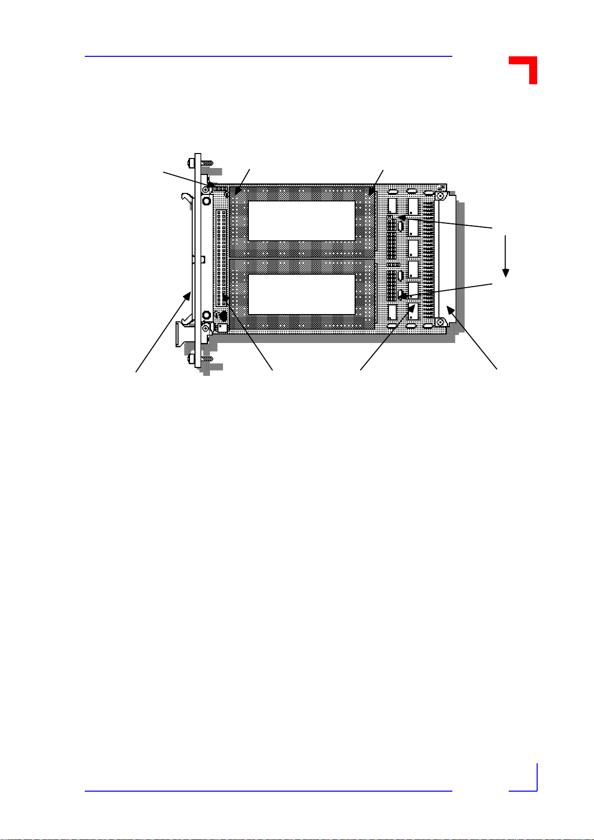
Figure 2-5: Overview of VMOD-2's Connector Locations
BU2a 26-way, 2-row
p i g g y bac k socke t for
upp e r piggyback
ST3 front p anel
connector (50-w a y)
— or —
ST 2 on- b oard
50-way header
BU2b 26-way, 2-row
p i g g y bac k socke t for
lower piggyback
BU1 a/BU0a 30/45-way
2/ 3 - row upper
pig gybac k s ocket
BU1 b/BU0b 30/45-way
2/3-r ow lower
pig gybac k s ocket
2.5.1VMOD-2's (VMOD/VME End) Piggyback Connector BU1/0
ST 1 VMOD -2's
VM E bus 96-way
connector (P1, J1)
12/15/97
The front two-rows of the three-row 30/45-pin sockets (BU1 and/or BU0) are used
by all VMOD/VMOD-2 piggybacks. Some piggyback's, having three-row headers,
also use the third row, BU0a or BU0b. The use of the third row does not however
define a piggyback as being only suitable for use on the VMOD-2, as the original
VMOD also had these third rows, and several existing VMOD-piggybacks use signals on the third row which are found on both the VMOD and the VMOD-2. Previously unused pins in the third row (BU0) are now fully utilized by the VMOD-2 and
Page 2 - 13Man. ID 03139, Rev. Index 0200
Page 40

VMOD-2/VMOD-2D
BU1 Connector
BU0 Connector
Signal
Pin #
Pin #
Signal
Pin #
Signal
to help see which pins are only on the VMOD-2, we have shown these additional
lines in bold/italics.
Functional Description
Table 2-7:
+5V (Vcc) 2 1 GND 1 GND
-12V 4 3 +12V 2 IA8
CLK 6 5 R /W* 3 IA9
UDTACK
n*
CSn* 10 9 INTAn* 5 IA11
IA71211INTn*6 IDS1*
IDS0*1413ID77 ID15
IAS* 16 15 ID6 8 ID14
IA61817ID59 ID13
IA5 20 19 ID4 10 ID12
VMOD/VMOD-2
8 7 RESET* 4 IA10
BU1/0 Connector Pin-Outs
IA4 22 21 ID3 11 ID11
IA32423ID212ID10
IA22625ID113ID9
IA12827ID014ID8
+5V (Vcc) 30 29 GND 15 GND
Notes:
1). All signals marked with an "*" are Active Low.
2). Lower case "n" used with some signal lines above is for the location identifier 0 or 1, where 0 = signal for upper piggyback location and 1 = lower piggyback location.
3). ±12V is only needed by some piggybacks, and will only be available if your
VMEbus backplane is connected to a PSU capable of supplying such voltages.
4). The orientation of the pin-number columns in the above connector overview
(and that of the connector overview on the next page) rel ates to the pin- positions of the VMOD-2 when viewed as shown in figure 2.5 on the preceding
page. I.e. their pin number 1s are top-right.
12/15/97
Page 2 - 14Man. ID 03139, Rev. Index 0200
Page 41

VMOD-2/VMOD-2D
VMOD-2 50-Way ST2/ST3 Pins as Used When a Selected Piggyback is
Fitted into the BU2 for Upper Location (A)
BU2 Pin #
VMOD-2 50-Way Pins Used When Piggyback is
Fitted into the BU2 for Lower Location (B)
Remember!
If any of the piggybacks you wish to use need any of the signals shown
bold/italic above (i.e. a 5230-xx typ e), a VMOD-2 set for an 8 KByte wide
address area must be used. Any piggyback not needing these additional
lines can be used on the VMOD-2 in either a 256 Byte or 8 KByte address
width setting.
Functional Description
2.5.2VMOD-2 External Interface Connectors BU2a and BU2b
The twenty-six pin double row sockets are totally isolated from the remaining circuits of the
VMOD-2, and only connect the input/output side of the respective piggybacks 26-pin I/O
header directly to the upper or lower half of the 50-way VMOD-2 front panel connector.
The actual pins used are subject to the design of the piggyback, but the pin interconnections
between the two BU2 connectors and the 50-way front panel connector will always be the
same. To determine what pin -s your si gnals wi ll a ppear on when using any re ady made pigg yback, please see the piggyback's user manual which will give precise details of the external
interfaces for use in both l ocations. If fault-tracing or designing your own piggybacks, the relationship of the respective piggyback locations (inputs/outputs) to the external connector is as
given in the table below.
Table 2-8: ST2/ST3 Connector Pin-Outs
50 24 2 1 24 50
47 21 4 3 22 48
45 19 6 5 20 46
43 17 8 7 18 44
41 15 10 9 16 42
39 13 12 11 14 40
37 11 14 13 12 38
359 16151036
337 18178 34
315 20196 32
293 22214 30
271 24232 28
49 23 26 25 23 49
12/15/97
Page 2 - 15Man. ID 03139, Rev. Index 0200
Page 42

VMOD-2/VMOD-2D
Caution!
The term "ST2" on th e schematics at the back of any pigg yback manuals,
refer only to the ST-2 conn ector of the actual pigg yback (which plugs into
the above BU2) not to the VM OD-2's ST2. Ta ke care not to confuse these
when making connections to your VMOD-2 front pane l.
Remember also that the pin-outs change when swapping the previously
fitted piggybacks around or replacing them with different types. This is
also true when mov ing several differently configure d VMOD-2's around in
your VMEbus system, where the external appearance of one VMOD-2 is
indistinguishable from any other.
Please refer to resp ective piggy backs use r's manu al for the ex act p in-outs
which are presented to the external equipment (the VMOD's 50-way
header) when such a p iggyback is fitted.
Functional Description
12/15/97
Page 2 - 16Man. ID 03139, Rev. Index 0200
Page 43

VMOD-2/VMOD-2D
Figure 2-6: VMOD-2 and VMOD-Piggyback Connector Overview
Functional Description
VMOD-2's ST2 (on-boar d)
50-way Header
Pin 50
Eve n
pins
Pin 2
VMOD
2
Pin 49
VMOD-2's ST3
Front Pa ne l
Connector
(50-Wa y )
Odd
pins
Pin 1
VMOD-2's two 26-way
Headers BU2a (upper)
BU2b (lowe r )
Position A
Fitted PB-REL
Position B
VMOD -2's two 30/45- way
Heade r BU1/0a (uppe r PB)
BU1/0b (lower PB location)
VMOD's ST1
VMEbus
Connector
(96-Wa y )
PB's ST2
Short
Connector
(26-Way)
26
Even
Pins
2
PB's ST1
PB-REL
(rea dy for fi tti n g)
PB's ST2 a nd ST1
25
Odd
Pins
1
pin distribution as
seen from th e PB's
component si de.
!
Rem ember t he PB's
ST2 pin numbers
have nothi ng to do
with the VMOD-2
ST2's (user I/O) pins.
30
Even
Pins
2
Long
Connector
(30-Way)
29
Odd
Pins
1
12/15/97
Page 2 - 17Man. ID 03139, Rev. Index 0200
Page 44

VMOD-2/VMOD-2D
Functional Description
2.5.3Pin Outs of the VMOD's Front Panel Connector with two VMOD-2s
The respective half of the VMOD-2's front panel 50-way connector (pins 1...24 for lower posi-
tion and pins 27.....50 for upper) assume the relationship of the piggybacks (as fitted to
VMOD-2) signals as routed from their ST2 (via the BU2a or BU2b) through connections as
shown in table 2.5.2 on previous page.
The connector's pins 25 and 26 a re u sed as an exter nal res et (or emergency s top loop ) on the
VMOD-2, and were left "not used" on the original VMOD.
An option to have the VMOD-2 with no front panel connector, but rather a 50-way header
behind a blank front panel will provide an identical pin-out to the standard 50-way front panel
connector, and is provided for applications where the flat band cabl e is to be routed internally,
or where an alternative front panel is to be fitted and used. Take care to note that the 50-way
header is unpolarized, and can be accidently missconnected if the flat-ribbon connector is
turned upside-down.
Figure 2-7: VMOD Front Panel Connector
Eve n p ins
Pin 50
Pin 2
VMOD
2
O dd pins
Pin 49
Pin 1
12/15/97
Note.
In systems having more than one connector of this type, or when using
several VMOD-2s with different piggybacks, it is advisable to put one or
two drops of colored paint on the back of the connector and on the front
panel of the VMOD-2 to which it was ma de for. The connector splits virtually in half (pins 1...24 and 27 to 50) for connection to the re spective piggybacks location behind it. Pins 25 and 26 are used by the "local reset"
Page 2 - 18Man. ID 03139, Rev. Index 0200
Page 45

VMOD-2/VMOD-2D
PB Name
and
Direction*
Signal*
VMOD Front (50-Way)
Pin #s
Piggyback
Position
PB ST2
Pins
input circuits where such feature is desired and thus enabled.
Table 2-9: VMOD-2 Front Panel Connector Pin-Outs
Functional Description
50 Upper (A) 1, 2
49 Upper (A) 25, 26
48 Upper (A) 3
47 Upper (A) 4
46 Upper (A) 5
45 Upper (A) 6
44 Upper (A) 7
43 Upper (A) 8
42 Upper (A) 9
41 Upper (A) 10
40 Upper (A) 11
39 Upper (A) 12
38 Upper (A) 13
37 Upper (A) 14
36 Upper (A) 15
35 Upper (A) 16
34 Upper (A) 17
33 Upper (A) 18
32 Upper (A) 19
31 Upper (A) 20
30 Upper (A) 21
12/15/97
29 Upper (A) 22
28 Upper (A) 23
27 Upper (A) 24
26 Reset GND
Page 2 - 19Man. ID 03139, Rev. Index 0200
Page 46

VMOD-2/VMOD-2D
PB Name
and
Direction*
Signal*
VMOD Front (50-Way)
Pin #s
Piggyback
Position
PB ST2
Pins
Table 2-9: VMOD-2 Front Panel Connector Pin-Outs
Functional Description
25 Reset +
Vcc
24 Lower (B) 1, 2
23 Lower (B) 25, 26
22 Lower (B) 3
21 Lower (B) 4
20 Lower (B) 5
19 Lower (B) 6
18 Lower (B) 7
17 Lower (B) 8
16 Lower (B) 9
15 Lower (B) 10
14 Lower (B) 11
13 Lower (B) 12
12 Lower (B) 13
11 Lower (B) 14
10 Lower (B) 15
09 Lower (B) 16
08 Lower (B) 17
07 Lower (B) 18
06 Lower (B) 19
05 Lower (B) 20
04 Lower (B) 21
12/15/97
03 Lower (B) 22
02 Lower (B) 23
01 Lower (B) 24
An identical table with appropriate signal names ready added, is to be found in
each piggyback manual.
Page 2 - 20Man. ID 03139, Rev. Index 0200
Page 47

This page was intentionally left blank.
Man. ID 03139, Rev. Index 0200
Page 48

VMOD-2/VMOD-2D
Configuration
3.2 Fitting Piggybacks
Detailed descriptions on how to fit and use each piggyback is given in their respective user's
manuals.
After fitting, please look under the fitted piggyback to ensure that every pin of it's front 26-pin
connector is in a socket hole. If any holes are not occupied or any pins are left without a hole,
there is a strong possibility that the piggyback is the wrong-way round and/or displaced in pin
number/height.
For many piggybacks the last 15-pin row of 30/45-pin socket holes (connector nearest the
VMEbus interface end of VMOD-2) will not be used. It is easier to see that all is well by checking the 26-pin interface at the front end first.
Pin-outs of the front panel 50-way connector will change according to the piggybacks fitted
and if they are used in the upper or lower locations. Again ple a se refer to the individual piggyback's user's manuals before making any interface cables.
12/15/97
Page 3 - 13Man. ID 03139, Rev. Index 0200
Page 49

VMOD-2/VMOD-2D
RQ Level
Wanted
B17
B18
B19
Local Reset
Enabled
Disabled
see note
below
Configuration
3.1.7Jumpers B17...B19 Setting Interrupt Level
The VMOD-2 user can set the three jumpers B17, B18 a nd B19 to us e any IRQ level from 1 to
7 as appropriate to his VMEbus systems application. When all three jumpers are set the IRQ
from the VMOD-2 is disabled.I
Table 3-10: IRQ Level selection
None Set Set Set
IRQ1* Set Set Open (Default)
IRQ2* Set Open Set
IRQ3* Set Open Open
IRQ4* Open Set Set
IRQ5* Open Set Open
IRQ6* Open Open Set
IRQ7* Open Open Open
3.1.8Jumper B20 Enable/Disable "Local" Reset Input
The VMOD-2 user can take advantage of an external signal which when utilized will allow the
two piggybacks to be "reset" whenever certain external conditions occur. The external twowire signal is input onto pins 25 and 26 of the 50-way external interface, where the wiring and
use of these two lines are as described in section 2.3.
Table 3-11: Local Reset Enable/Disable
Jumper B20 1-3 1-2 Open
Note.
Jumper B20 must be set to either 1-2 or 1-3. B20 left open is not allowed.
If this jumper is left totally open (neither pin con nected to pin 1) the logic
is floating and may cause spurious resets or other unpredictable problems.
12/15/97
Page 3 - 12Man. ID 03139, Rev. Index 0200
Page 50

VMOD-2/VMOD-2D
B16
AB Size
Address
Block #s
B2 A15
B12 A14
B13 A13
B14 A12
B15 A11
Address Range
From ... To
Table 3-9: Address Width (B16) and Range (B2 and B12...15) Selections
Open 2 56 Byte AB #3 1 Open Open Open Open Set $FE F4 00 $ FE F4 FF
Open 2 56 Byte AB #3 2 Open Ope n Open Open Open $FE FC 00 $FE FC FF
Set 8 KByte AB#01..04 Set Set Set x x $FE 00 00 $FE 1F FF
Set 8 KByte AB#05..08 Set Set Open x x $FE 20 00 $FE 3F FF
Set 8 KByte AB#09..12 Set Open Set x x $FE 40 00 $FE 5F FF
Set 8 KByte AB#13..16 Set Open Open x x $FE 60 00 $FE 7F FF
Set 8 KByte AB#17..20 Open S et Set x x $FE 80 00 $FE 9F FF
Set 8 KByte AB#21..24 Open S et Open x x $FE A0 00 $FE BF FF
Configuration
Set 8 KByte AB#25..28 Open Open Set x x $FE C0 00 $FE DF FF
Set 8 KByte AB#29..32 Open Open Open x x $FE E0 00 $FE FF FF
12/15/97
x = B14 and B15 can be left at any setting when using 8 KByte address block widths. Default Setting bold/italic
Page 3 - 11Man. ID 03139, Rev. Index 0200
Page 51

VMOD-2/VMOD-2D
B16
AB Size
Address
Block #s
B2 A15
B12 A14
B13 A13
B14 A12
B15 A11
Address Range
From ... To
Table 3-9: Address Width (B16) and Range (B2 and B12...15) Selections
Open 2 56 Byte AB #16 Set Open O pen O pen Op en $FE 7C 00 $FE 7C FF
Open 2 56 Byte AB #17 Open Set Se t Set Set $FE 84 00 $FE 84 FF
Open 2 56 Byte AB #18 Open Set Se t Set Open $FE 8C 00 $F E 8C FF
Open 2 56 Byte AB #1 9 Open Set Set Op en Set $FE 94 00 $FE 94 FF
Open 2 56 Byte AB #20 Open Set Se t Open Ope n $FE 9C 00 $ FE 9C FF
Open 256 Byte AB #21 Open Set Open Set Set $FE A4 00 $FE A4 FF
Open 256 Byte AB #22 Open Set Open Set Open $FE AC 00 $FE AC FF
Open 2 56 Byte AB #2 3 Open Se t Open Open Set $FE B4 00 $FE B4 FF
Configuration
Open 256 Byte AB #24 Open Set Open Open Open $FE BC 00 $FE BC FF
Open 256 Byte AB #25 Open Open Set Set Set $FE C4 00 $FE C4 FF
Open 256 Byte AB #26 Open Open Set Set Open $FE CC 00 $FE CC FF
Open 256 Byte AB #27 Open Open Set Open Set $FE D4 00 $FE D4 FF
Open 256 Byte AB #28 Open Open Set Open Open $FE DC 00 $FE DC FF
Open 2 56 Byte AB #29 Open Open Open Se t Set $FE E 4 00 $FE E4 FF
Open 256 Byte AB #30 Open Open Open Set Open $FE EC 00 $FE EC FF
12/15/97
Page 3 - 10Man. ID 03139, Rev. Index 0200
Page 52

VMOD-2/VMOD-2D
B16
AB Size
Address
Block #s
B2 A15
B12 A14
B13 A13
B14 A12
B15 A11
Address Range
From ... To
Table 3-9: Address Width (B16) and Range (B2 and B12...15) Selections
Open 2 56 Byte AB #01 Set S et Set Set Set $FE 04 00 $FE 04 FF
Open 256 Byte AB #02 Set Set Set Set Open $FE 0C 00 $FE 0C FF
Open 2 56 Byte AB #0 3 S et Set Set Open Set $FE 14 00 $FE 14 FF
Open 256 Byte AB #04 Set Set Set Open Open $FE 1C 00 $FE 1C FF
Open 2 56 Byte AB #05 Set S et Op en Se t Set $FE 24 00 $ FE 24 FF
Open 256 Byte AB #06 Set Set Open Set Open $FE 2C 00 $FE 2C FF
Open 256 Byte AB #07 Set Set Open Open Set $FE 34 00 $FE 34 FF
Open 256 Byte AB #08 Set Set Open Open Open $FE 3C 00 $FE 3C FF
Configuration
Open 256 Byte AB #09 Set Open Set Set Set $FE 44 00 $FE 44 FF
Open 256 Byte AB #10 Set Open Set Set Open $FE 4C 00 $FE 4C FF
Open 256 Byte AB #11 Set Open Set Open Set $FE 54 00 $FE 54 FF
Open 256 Byte AB #12 Set Open Set Open Open $FE 5C 00 $FE 5C FF
Open 2 56 Byte AB #13 Set Open O pen Set Set $FE 64 00 $FE 64 FF
Open 256 Byte AB #14 Set Open Open Set Open $FE 6C 00 $FE 6C FF
Open 2 56 Byte AB #1 5 S et Ope n Open Open Set $FE 74 00 $FE 74 FF
12/15/97
Page 3 - 9Man. ID 03139, Rev. Index 0200
Page 53

VMOD-2/VMOD-2D
#
Configuration
Vector Modes
B1 Settings
B4...B11
Settings
Table 3-8: Interrupt Vector Configuration Examples
Configuration
2b) Two piggybacks, both
unable to generate interrupt vectors but can send
interrupt request are fitted
to the VMOD-2 and use
"Dumb" vectors (e ach with
Use a different
Jumper set
VMOD-2 Vector for each
piggyback
B1 is t o b e
set to 1-2.
Jumpers
B4...B11 are
set for appropriate byte coding. B11 is set
to 1-3.
different vector)
3) One "intelligent" and one
"Dumb" piggyba ck are t o
be fitted to the VMOD-2
and the user wants the
intelligent piggyback to
use it's on-board "Intelligent" vector generation in
combination with "Dum b"
Use the
"Dumb" piggyback in upper
location, and
fit the "in telli gent" one in
lower location.
B1 is t o b e
set to
bridge pins
1-3.
Jumpers
B4...B11 are
set for desired
vector code to
be assigned
when piggyback "A"
makes an IRQ.
jumper coding.
3.1.6Jumper B16 Selecting Address Block Width
Via the jumper B16, you are able to select if your VMOD-2 should occupy 256 Bytes of
address space, or when using certain enhanced piggybacks (which need/use additional
address decoding of A06...A11), in increased address steps of 8 KByte wide. The 256 byte
wide steps are numbered as AB (Address Blocks) from 01 to 32 in the table below.
Whenever the 8 KByte option is selected (i.e. jumper B16 is set) four consecutive AB#s are
occupied. These are also given to ensure that no address contention will occur when using
several VMOD-2's (and/or other boards) in your VMEbus system.
12/15/97
Page 3 - 8Man. ID 03139, Rev. Index 0200
Page 54

VMOD-2/VMOD-2D
Interrupt Vector Selection (With Jumper B1 BeingCompletely Open)
Interrupt Vector
Bit
Jumper Numbers
Jumper Decod-
ing
Upper PBs Vec-
tor
Lower PBs Vec-
tor
#
Configuration
Vector Modes
B1 Settings
B4...B11
Settings
Table 3-7:
See also table 3-8 below for further interrupt vector setting information,
which may be helpful to you, in order to see how and when to use the
three-pin setting option s of jumpers B1 an d B11.
Configuration
D7 D6 D5 D4 D3 D2 D1 D0
B04 B05 B06 B07 B08 B09 B10 B11
May be any setting "Don't Care" since these settings are ignored
Derived from "intelligent" piggyback
Derived from "intelligent" piggyback
3.1.5Using Interrupt Vector
Jumpers B4... B11 as described in the preceding section, provide a binary coded interrupt
vector, and may be freely programmed with each jumper representing an individual data bit,
B4 = MSB and B11 = LSB.
The table below will help you to decide when and how to use which settings, according to
what facilities your chosen piggybacks support.
Table 3-8: Interrupt Vector Configuration Examples
1) Two piggybacks, both able
to generate interrupt vectors are fitted to the VMOD2 and the user wants "intelligent" vectors.
2a) Two piggybacks, both
unable to genera te interrupt vectors but can send
interrupt request are fitted
to the VMOD-2 and use
"Dumb" vectors (both the
Use Piggyback
Generated
Vectors
Use the same
Jumper set
VMOD-2 Vector for both Piggybacks
Jumper B1
is left open.
B1 is to be
set to 1-2.
Jumpers
B4...B11 ar e
not decoded
and can be left
in any setting.
Jumpers
B4...B10 ar e
set for appropriate byte coding. B11 is set
to 1-2.
same vector)
12/15/97
Page 3 - 7Man. ID 03139, Rev. Index 0200
Page 55

VMOD-2/VMOD-2D
Example Setting
#1
Upper PBs Vec-
tor
Lower PBs Vec-
tor
Example Setting
#2
Upper PBs Vec-
tor
Lower PBs Vec-
tor
Example Setting
#3
Upper PBs Vec-
tor
Lower PBs Vec-
tor
Interrupt Vector
Bit
Jumper Numbers
Example Setting
#1
Upper PBs Vec-
tor
Lower PBs Vec-
tor
Lower PBs Vec-
tor
Table 3-5: Interrupt Vector Selection (With Jumper B1 Set to 1-2)
Configuration
Open Open Open Open Set Open Set 1-3*
F4
F5
Open Open Open Open Set O pen Set 1-2*
F4
F4
Open Open Open Open Set O pen Set Op en
F5
F5
* = With jumper B11 set for 1-3, D0 will retur n a "0" for pi ggyba ck "A" and a "1" for
piggyback "B".
With jumper B11 set to 1-2, the vector of both piggyback locations "A" and "B" will
be the same (so D0 = 0).
With jumper B11being open, the vector of both piggyback locations "A" and "B"
will also be the same (but D0 = 1).
Table 3-6: Interrupt Vector Selection (With Jumper B1 Set to 1-3)
D7 D6 D5 D4 D3 D2 D1 D0
B04 B05 B06 B07 B08 B09 B10 B11
Open Open Open Open Set O pen Set 1-2
F4
12/15/97
Derived from "intelligent" piggyback
Derived from "intelligent" piggyback
Page 3 - 6Man. ID 03139, Rev. Index 0200
Page 56

VMOD-2/VMOD-2D
Configuration for Base Address Range $FE2400 to $FE24FF
Selecting Address Modif iers (AM) Options
Address
Modifier
Standard
39/3D/00
Short 29/2D
Interrupt Vector
Bit
Jumper Numbers
the number of address setting options decrease to just eight. See section 3.1.6 for the
description of jumper B16s function and the entire "addr ess setting options" table.
Configuration
Table 3-3: Setting the VMOD-2 Base Address
VMOD-2 Jumpers B02 B12 B13 B14 B15 Base Addr
Default Sett ings Set Set Open Set Set $FE2400
Address Lines A15 A14 A13 A12 A11
A jumper set results in the related address line being assigned a logical low (0) function.
Remember!
When replacing an existing "Original-VMOD" only eight addresses were
available $FE0400 (as per default above), and addresses equal to AB#05,
AB#09, AB#13, AB#17, AB#21, AB#25 and AB#29 as shown in table 3-6.
3.1.3Jumper B3 Address Modifiers
Jumper B3 provides the VMOD-2 user with two different address modifier options. The user
can have Short Access, 29/2D, or Standard Access, 39/3 D/00.
Table 3-4:
Jumper B3 Open Set
3.1.4Jumper B4...B11 Interrupt Vector
Jumpers B4... B11 provide a binary coded interrupt vector, B4 = MSB, which subject to the
setting of jumper B01, may be used to give an interrupt vector for either or both piggybacks.
The user can have these settings ignored when using two "intelligent" piggybacks (i.e. capable of generating on-board interrupt vectors), by setting jumper B01 to fully open.
The jumper B11 is a three-pin type and can be used to differentiate when the user wants the
piggybacks to have identical or different Interrupt Vector Addresses.
Table 3-5: Interrupt Vector Selection (With Jumper B1 Set to 1-2)
D7 D6 D5 D4 D3 D2 D1 D0
B04 B05 B06 B07 B08 B09 B10 B11
12/15/97
Page 3 - 5Man. ID 03139, Rev. Index 0200
Page 57

VMOD-2/VMOD-2D
Desired Vector Source
Jumper B1
Notes
Jumper
Number
Default
Setting
Brief Functional Description
See Ch.
#
Configuration
Table 3-1: General Overview of the VMOD-2 Jumpers
B17 Set MSB of IRQ* level coding 3.1.7
B18 Set 2nd bit of IRQ* level coding 3.1.7
B19 Open LSB of IRQ* level coding 3.1.7
B20 1-2 External "local" Reset input is Disabled. 3.1.8
* = Three pin jumper type with default having no pins connected.
3.1.1Jumper B1, Selecting Interrupt Vector Options
Jumper B1 provides the selection of how your VMOD-2 or it's piggybacks may provide the
interrupt vector to the VMEbus, as shown in the followi ng table.
Table 3-2: Selecting Interrupt Vector Source (PB or VMOD-2)
From either of the two
Open Default Setting
"Intelligent" PBs
From VMOD-2's B4..B11
settings
From "Intelligent" PB in "B"
location (lower) & from
VMOD-2 for "A"
Set 1-2 For 2 x "dumb"
PBs
Set 1-3 Ensure the PB fit-
ted in the lower
PB location supports this feature
Note!
If wanting mixed "Intelligent and Dumb" interrupt vector support, fit the
"dumb" piggyback into the upper location (to use the VMOD-2's preset
jumper vectors) and the "in telligent" piggyback in to the lower location.
3.1.2Jumpers B2, B12...B15 Selecting Base Address
Via the five jumpers B02, B12, B13, B14 and B15, you are able to set your VMOD-2's base
address in steps of 256 Bytes, to any desired base address from $FE 04 00 to $FE FC 00. In
all permitting up to 32 di fferen t add ress setti ng opti ons. I f jumper B16 i s set, the address s teps
increase in width to 8 KByte (jumper settings of B14 and B15 are no longer interpreted), and
12/15/97
Page 3 - 4Man. ID 03139, Rev. Index 0200
Page 58

VMOD-2/VMOD-2D
Jumper
Number
Default
Setting
Brief Functional Description
See Ch.
#
However, you are strongly recommended to check these delivered settings against the function set (your piggyback's needs) you require, in order to ensure that the VMOD-2 and your
system will function correctly.
Table 3-1: General Overview of the VMOD-2 Jumpers
B01 Open* Interrupt vectors generated by PB's 3.1.1 & 4
Configuration
B02 Set Selects Address line A15's decoding to
"0"
B03 O pen Standard Ac cess 39 /3D/00 3.1.3
B04 Open Bit D7 of VMOD-2's Interrupt vector set
to logical "1"
B05 Open Bit D6 of VMOD-2's Interrupt vector set
to logical "1"
B06 Open Bit D5 of VMOD-2's Interrupt vector set
to logical "1"
B07 Open Bit D4 of VMOD-2's Interrupt vector set
to logical "1"
B08 Open Bit D3 of VMOD-2's Interrupt vector set
to logical "1"
B09 Open Bit D2 of VMOD-2's Interrupt vector set
to logical "1"
B10 Open Bit D1 of VMOD-2's Interrupt vector set
to logical "1"
3.1.2
3.1.4
3.1.4
3.1.4
3.1.4
3.1.4
3.1.4
3.1.4
12/15/97
B11 Open* Bit D0 of VMOD-2's Interrupt vector set
to logical "1"
B12 Set Selects Address line A14's decoding to
"0"
B13 Open Selects Address line A13's decoding to
"1"
B14 Set Selects Address line A12's decoding to
"0"
B15 Set Selects Address line A11's decoding to
"0"
B16 Open Address width selected for 256 Bytes. 3.1.6
3.1.4 & 5
3.1.2
3.1.2
3.1.2
3.1.2
Page 3 - 3Man. ID 03139, Rev. Index 0200
Page 59

VMOD-2/VMOD-2D
Configuration
3. Configuration
This section describes how to instal the VMOD-2's piggybacks, set the necessary jumpers,
and in general prepare the VMOD-2 for system operation. Before you proceed with this section, please refer to the chosen piggybacks user's manuals, to see what restricti ons or special
needs are to be taken into account, regarding their use with the VMOD/ VMOD-2 base module.
3.1 Jumper locations and functions
The VMOD-2 possesses some twenty jumper selectable options, such as choice of physical
Address Block Size, Base Address, Address Modifiers, etc. These may be via simple "set" or
"open" two-pin jumpers, or through bridging two-pins of a three-pin jumper.
Figure 3-1 gives the VMOD-2's physical jumper locations, types and of especial importance
for the three-pin types the locations of the pin numbers which are used as setting references
throughout this chapter. Thereafter the jumpers are described individually in function order.
Figure 3-1: Jumper Locations Overview
B20
2 - 1 - 3
See p iggybac k A 's
m anual for details of
it's jum p ers/settings
See p iggybac k B's
m anual for details of
it's jum p ers/settings
B01
BO2
B03
B04
B05
B06
B07
B08
B09
B10
B11
B12
B13
B14
B15
B16
B17
B18
B19
3
1 2
2 - 1 - 3
The significance of the "2 1 3's" in the above figure is to define the pin setting choices which
these three pin jumpers offer e.g. jumper set onto pins 1-2 or onto 1-3. Pin 1 is always in the
middle of these three pin groups.
VMOD-2 is factory tested for full functionality, and is delivered in the configuration which best
suits the majority of users (default set ti ngs), see table 3-1 on the next page.
12/15/97
Page 3 - 2Man. ID 03139, Rev. Index 0200
Page 60

VMOD-2/VMOD-2D
Configuration
Configuration
3.1 Jumper Locations and Functions........................................... 3-1
3.1.2 Jumpers B2, B12...B15 Selecting Base Address.......... 3-3
3.1.3 Jumper B3 Address Modifiers....................................... 3-4
3.1.4 Jumper B4...B11 Interrupt Vector ................................. 3-4
3.1.5 Using Interrupt Vector................................................... 3-5
3.1.6 Jumper B16 Selecting Address Block Width................. 3-6
3.1.7 Jumpers B17...B19 Setting Interrupt Level................... 3-7
Chapter
3
3.1.8 Jumper B20 Enable/Disable "Local" Reset Input.......... 3-7
3.2 Fitting Piggybacks................................................................. 3-7
12/15/97
Page 3 - 1Man. ID 03139, Rev. Index 0200
Page 61

VMOD-2/VMOD-2D
Installation
Installation
Chapter
4
4.1 VMEbus Connection.............................................................. 4-1
4.2 Installing the VMOD-2........................................................... 4-1
4.2 IChronological Installation Procedure.................................... 4-2
4.4 Connecting the External Devices .......................................... 4-3
4.5 Front Panel Functions........................................................... 4-4
4.6 Trouble-shooting for VMOD-2/VMOD and VMEbus System. 4-5
4.7 General Remarks on the Use of Your System ...................... 4-6
12/15/97
Page 4 - 1Man. ID 03139, Rev. Index 0200
Page 62

VMOD-2/VMOD-2D
Installation
4. Installation
This section describes how to install the VMOD-2 fitted with one or two piggybacks for use in
your VMEbus system. Before you proceed with this section please make sure that you have
configured all of the necessary VMOD-2 jumpers as described in the preceding section.
4.1 VMEbus Connection
Caution!
Before installing or removing any VMEbus boards always turn off the
power to the bus and an y external periphera ls.
Inserting or removing VMOD-2 mo dules while power is on could result in
damage to the VME module o r peripherals interface.
Please refer to the Piggyback/-s user's manual/-s for details on installing/removing VMOD to/
from your VMEbus system.
4.2 Installing the VMOD-2
The VMOD-2 may be plugged into any free VMEbus slot position (other than slot 1) in your
VMEbus system.
Note: Check Piggybac ks Fitting
(1/.) The connecto r at one end of th e piggyb ack has less pin s than th at at
the other end.
(2/.) The piggyback ST2 ha s two-rows which are to fit the front two -rows
of the VMOD-2 26-pin, two-row int erface socket BU 2. Take care to ensu re
the piggyback is in its co rrect position/orienta tion.
In addition to the mechanical retention/support provided by the two piggyback interface connectors, the piggyback may (by customers with high vibration applications) be held to the
motherboard by screws and stand off pillar s, sin ce at t he front end of the pigg yback and at the
corresponding location on the VMOD-2, two holes per piggyback location, are provided for
this purpose.
4.3 Chronological Installation Procedure (VMOD-2)
1/. Inspect the 96 way VMEbus Interface Connector and front panel header (50-way con-
nector) for clean straight pins.
2/. Check the fitted piggybacks and desired VMOD-2 jumper settings suit your intended
application. i.e. jumper B16 "Set" (for 8 KByte block width) when using any 5230-xx piggybacks.
12/15/97
Page 4 - 2Man. ID 03139, Rev. Index 0200
Page 63

VMOD-2/VMOD-2D
3/. Check the desired external interface leads, lengths and connector orientations suit your
intended application and match the connector types required for your targeted external
devices.
4/. Ensure all power is off, including that to all other devices connected to the VMEbus sys-
tem.
5/. Choose the desired slot for your VMOD-2 with it's chosen piggyback(s) , and if neces-
sary reposition the other modules. For this chosen slot you must remove the IACK*
daisy chain jumper. (See figure 4.3 on next page).
6/. Place the PCB into the card guides for the desired slot.
7/. Push the module into it's position carefully, checking that the flat ribbon cable (if con-
nected to optional internal 50-way header) does not become snared or damaged. Once
the insertion force of the 96 way VMEbus connector has been overcome, the fr ont pan el
securing screws can be tightened up.
8/. To ensure reduced risk of shock hazard when using higher voltage piggybacks, fit cov-
ers to unused slots either side of the slot into which the VMOD-2 with such piggybacks
is to be fitted.
Installation
9/. Connect the flat ribbon interface cables to your chosen external devices.
10/. Restore power only when you are satisfied that all the modules are correctly electrically
and mechanically fitted.
Removing the VMOD-2 (or any other PepCard) is virtually the reverse procedure, where it is
especially important to remember when removing any modules like the VMOD-2, with the
option for externall y powe red devi ces, et c. to po wer d own eac h of t hese external source s and/
or disconnect the external connector, otherwise you may risk short-circuiting the external
devices power supply outputs, with risk of damage to the interface leads, the interface on the
piggyback and even the circuit traces on the VMOD module itself.
12/15/97
Page 4 - 3Man. ID 03139, Rev. Index 0200
Page 64

VMOD-2/VMOD-2D
Figure 4-1:Location of jumpers on a VBP or VBP2 VMEbus backplane
VMOD-2
Installation
BG3*
IACK*
SLOT #1
SLOT #1
VM20 Processor Board
as sys tem controller
re move BG 3* and
IAC K* Jumpers
Termi nation network
resistor pu ll-up p a cks
SLOT #n
SLOT #1
Where VM OD-2 is to
be fitted, always
remove the IACK*
Jumper
J umpers se t for e mpty
slots or where ver
PepCards without any
Daisy chain handling
a bility are fitted.
4.4 Connecting the External Devices
If you are using any external leads which carry any voltag e, do not plug the ext ern al leads i nto
the front panel connector until after the VMOD-2/Piggyback(s) assembly has been installed in
to the rack. The reasons are as follows;
1/. For any external voltages (either under or over 50 Vdc) a risk of electrical shorts exist if
the assembled VMOD-2 is laid onto any conductive surfaces, including anti-static workbench mats, etc.
2/. If your external power units are not protected by fuses (in all lines) there i s a risk of lines
being accidently shorted when the modules are pushed in/or pulled out of the rack. In
particular their is a chance that lines from different external equipments can be shorted
together or to the VMEbus system's frame ground if the solder side of the VMOD-2's
BU2a and/or BU2b pins and/or the solder side of the piggyback ST2 or ST3 pins touch
the front panel of the module already fitted in the adjacent slot.
3/. If the external voltages exceed 50 Vdc, personnel are exposed to risk of elect rical shock
from solder side of the piggyback and the VMOD-2, i.e. from solder pads under the
VMOD-2 50-pin connector.
We also recommend that where possible no external power be present on the external connector when making/breaking the connection, as this can degrade the connectors life.
12/15/97
Page 4 - 4Man. ID 03139, Rev. Index 0200
Page 65

VMOD-2/VMOD-2D
The recommended maximum cable length should be limited to 5 meters (~15 feet) to ensure
minimum voltage drop/risk of cables becoming damaged/trapped, etc
Caution!
Ensure that the current ratings of the connected flat-band cables are
never exceeded.
Installation
4.5 Front Panel Functions
The front panel of the VMOD-2 has only the 50-pin connector on it. The odd numbered pins of
this connector are on the right side when looking at the connector from the VMOD-2's front
(see figure 4.5 below). The even pins are on the left si de of the connector and the lowes t numbers for each (odd and Even) row are at the bottom ascending. Depending on where your
VMOD-2 piggyback is fitted, you will need to use the lower half of this connector or the upper
half.
The connector (front-panel connector onl y) is provi ded with a pol arizi ng keyw ay to ensure t hat
the made up cable cannot be inserted up-side-down (therefore to the wrong piggybacks and
with reversed connections) if at any time it has been disconnected. Two retainer/ejectors lock
the connector into place and/or help to eject it during disconnection.
To help differentiate between cables for interfacing with differently configured VMOD/VMOD2s we recommend a drop of colored paint be placed on the back of t he connector and ont o the
front panel of the VMOD to which this cable should fit. This could be very important and save
considerable time later if reconfiguring your VMEbus system. Further, in very large systems,
or where lot's of VMOD/VMOD-2's are in use, two drops of paint at the top and bottom of the
connector and on the ends of the retaining latches could provide an at-a-glance confirmation
of both piggyback types before making connections.
12/15/97
Page 4 - 5Man. ID 03139, Rev. Index 0200
Page 66

VMOD-2/VMOD-2D
Figure 4-2: VMOD Standard front panel layout
Installation
Even pins
Pin 50
Pin 2
VMOD
Od d pi n s
Pin 49
Pin 1
The standard 3U high fascia may be replaced with a 6U (double height) front panel for use in
6U VMEbus systems. If making up your own double-height front panel, the VMOD must be so
placed that it uses the upper connector of any desired VMEbus slot. Alterantly a suitable 6U
fascia may be obtained fr om your local PepCard supplier, or even be specified for pre-assembled 6U VMOD-2 and/or piggyback configurations during the initial ordering stage.
4.6 Trouble-Shooting for VMOD-2/VMOD and VMEbus System
This section is intended to assist users of the VMOD-2 and/or some of it's piggybacks to
quickly resolve any problems they may encounter in their application. It is by no means com-
12/15/97
Page 4 - 6Man. ID 03139, Rev. Index 0200
Page 67

VMOD-2/VMOD-2D
Problem
Possible Ca use or Solu tio n
Action
prehensive, and relies upon the user feed-back to make us aware of any such experiences.
Please also see similar table in the respective piggyback user's manual.
Installation
Table 4-1: Indications on Trouble-Shooting
None of the exte rnally connected
devices have correct
or expected function
with the VMOD-2's
outputs
The external interface connector connects to the wrong half of the front
panel connector (i.e. pins 01 to 24
instead of pi ns 2 7 to 50 f or up p er p ig gyback position). Move piggyback to other
location if this appears to be the case,
and test from there before rewiri ng you r
interface cabl e.
a) the flat ribbon cable is fitted wrong
way up into the IDC connector i.e Pin 1
is connected to wire #50, etc.
The piggyback ha s been ac cident ly set
back one whole pin-row so only half it's
output connectors are connected to the
external inte rface an d it's inp uts are
misconnected to the VMOD's logic
interface/power.
a) The piggyback was displaced in the
BU1/0 and BU2 connectors by 180°
If you have made such a connection
then the VMOD-2 has been designe d
that no damage to it or the piggyback
should occur. Move the piggyback forward to the correct location and test for
correct function. If the piggyback or
VMOD-2 does become damaged
through misconnections of this kind, the
PEP warrantee is invalidated.
See Sect. 2.4 .3 for
precise front panel
pin-outs.
Check Physical configuration .
12/15/97
Where opto-isolated piggybacks are
used, your external supply has failed or
has been turned off, gone into current
limit, or has had a fuse failure.
Check PSU
.
Page 4 - 7Man. ID 03139, Rev. Index 0200
Page 68

VMOD-2/VMOD-2D
Problem
Possible C aus e o r So lutio n
Action
Table 4-1: Indications on Trouble-Shooting
Installation
An unknown problem
prevents the selected
piggyback(s)/VMOD2 configuration from
functioning.
If the VMOD-2 functioned before, and
has been reconfigured for a new application/address/piggyback, steps 1 to 3
may help find/confirm the faulty area.
If the piggyback appears to function
correctly with other VMOD-2s or in
VMOD-2's other piggyback location the
problem could be damaged or burnt out
tracks which may not have used/
needed by the last piggyback fitted.
If the piggyback will not function with
other VMODs or in VMOD's other location the problem is alm ost cer ta in ly du e
to the piggyback or the application software.
1) Replace previo us
known working configuration and try for
correct fun ction of
VMOD-2.
2) Put piggyback into
other location on
VMOD-2 or if available onto another
VMOD/VMOD-2 module and test for correct piggyback
function.
4.7 General Notes for Using the System
Having designed a fully-functioning system, the only thing that remains is to keep it in good
health. The three biggest areas of risk to your system are at the following times:
• Connecting peripherals, disk-drives, printers, terminals and external
power sources.
• Adding or changing modules, address settings and locations, etc.
• Becoming complacent and no t r ef erri n g to th e man ua l s when al te rin g o r
adding modules.
The way to reduce these risk is;-
• to check the electrical compatibility of all devices which you intend to
connect to your system, -
• to ensure that they are powered from the same mains supply branch
(phase) and grounded to the same reference point, -
• to shut down all power before making or breaking any connections to
12/15/97
Page 4 - 8Man. ID 03139, Rev. Index 0200
Page 69

VMOD-2/VMOD-2D
modules or attachments to the system, including power to the peripherals. -
• to observe sensible static protection procedures before handling any
modules, piggy-backs or memory IC's.
• to keep all manuals handy, near to the system at all times and refer to
them when the need arises.
Some Tips are:-
• PepCards are not over sensitive to static, but it is generally advisable to
observe sensible procedures such as:
• When configuring the module do not take it out of the original packing
unless necessary, the new clear packs may be o pen ed a nd th e jumpe rs
set, piggybacks added, etc. without needing to remove the card. This
also prevents you inadvertently shorting any on-board batteries, etc.
• When inserting modules into a system, just turn the power off, do not
remove the mains lead!, as it's ground wire prevents the rack floating
with dangerous static vo ltages, which could de str oy cir cui ts on the module you are trying to insert.
• Touch the front panel of the module you wish to insert, or the shell of
the connector you wish to connect to any part of the rack , before fitting,
to discharge any static from you the carrier.
• Disconnect an y leads connected to a module before undo ing it's front
panel securing screws and pulling it out of the rack, put modules into
the rack before connecting any front-panel connectors.
• Do not just pull modules straight out of a rack, check if they have cables
to unplug behind t he front panel (suc h as the VSBC-1's 40-pin parallel
on-board headers) and ensure that these cables if fitted have enough
play to allow the modules concerned to be removed far enough to
detach these cables.
• Park "pulled" jumpers onto one of the pins they would normally bridge,
so they are available for quick replacement should the configuration
change later.
• Remember to check the mains input voltage selector switch before
installing or using any PSU!
• Fill out the configur ation card (in the ap pendix of this manual) with the
up-to-date (latest) system configuration data , e.g . which modu le is fitte d
where and what addresses they are set to, etc. and refer to this when
investigating any problems or requesting any form of support from PEP
or it's authorized agents.
Installation
If you wish you may copy the configurati on card, to write on the copy , keep a conf iguration hi story to return to, and keep the master clean for future use. Or you may choose to enter details
in pencil, to enable erasures and corrections to be easily made.
In the event of any "mystery" problems, such as those where a card sent for repair is r e turned
as having "no actual defect" or another tried card has the same symptoms. It is very often the
actual configuration which has led to the "apparent fault". With the many thousands of combinations in which these cards could be employed, our repair department would never be able
12/15/97
Page 4 - 9Man. ID 03139, Rev. Index 0200
Page 70

VMOD-2/VMOD-2D
to reconstruct the configuration which gives your problem credence, just by co-incidence.
Therefore if you could send a copy of this configuration card, along with the module and it's
repair request form, to the place of original sale, then, in the event the card passes normal
test, we will (if n e cessary) be able to set up a configuration, similar t o yours, and test for sati sfactory function, or give expert advice on system configuration problems your layout has (or
may) encountered.
Sometimes these are simple things, which can be resolved without any test or repair being
necessary, such as moving an address so it does not clash with that used by another card. If
we save time investigating the fault, then you save time and cost involved with unnecessary
testing and "back and forth" shipping and enquiri ng later.
Installation
12/15/97
Page 4 - 10Man. ID 03139, Rev. Index 0200
Page 71

VMOD-2/VMOD-2D
System Configuration Record
System Configuration Record
Annex
A
12/15/97
Page A - 1Man. ID 03139, Rev. Index 0200
Page 72

VMOD-2/VMOD-2D
G
System Configuration Record
Us e thi s f or m to keep an up t o date r ecor d of your s y s tems conf i gur ati on
R ACK #
POW ER SUPPLY
MO DULE (O R T Y PE ) BAS E ADDRESS IRQ LEVEL & V ECT OR
MAKE
System Configuration Record
BACKPLANE
JUMPERIN
BG0*
BG1*
POWER OUT PUT VOLTAGE INPUT
BG2*
BG3*
IAC K*
VMEb u s B AC KPLANE
SLO T 1
SLOT 2
SLOT 3
SLOT 4
SLOT 5
SLOT 6
SLOT 7
SLOT 8
SLOT 9
SLOT 10
SLOT 11
SLOT 12
SLOT 13
SLOT 14
SLOT 15
MAKE
SIZE
TERMINATION
SLOT 16
SLOT 17
SLOT 18
SLOT 19
SLOT 20
SLOT 2 1
IIOC BA CKPLAN E
FDD #0
FDD #1
HDD # 0
HD D # 1
SOFTWA RE USED
TYPE
SIZEMAKE
SIZEMAKE
SIZEMAKE
SIZEMAKE
SIZEMAKE
REVISION
FL OPPIES USED
FL OPPIES USED
12/15/97
Page A - 2Man. ID 03139, Rev. Index 0200
Page 73

VMOD-2/VMOD-2D
System Configuration Reco rd
Us e thi s s i de to keep a n up to date r ecor d of your s ys tems exter nal y connected p er i pher al s
System Configuration Record
12/15/97
Page A - 3Man. ID 03139, Rev. Index 0200
Page 74

This page was intentionally left blank.
Man. ID 03139, Rev. Index 0200
Page 75

VMOD-2/VMOD-2D
VMOD-2 Board Layout
VMOD-2 Board Layout
Annex
B
12/15/97
Page B - 1Man. ID 03139, Rev. Index 0200
Page 76

VMOD-2/VMOD-2D
VMOD-2 Board Layout
12/15/97
Page B - 2Man. ID 03139, Rev. Index 0200
Page 77

Page 78

Page 79

VMOD-2/VMOD-2D
VMOD-2 Schematics
VMOD-2 Schematics
Annex
C
12/15/97
Page C - 1Man. ID 03139, Rev. Index 0200
Page 80

VMOD-2/VMOD-2D
VMOD-2 Schematics
12/15/97
Page C - 2Man. ID 03139, Rev. Index 0200
Page 81

Page 82

 Loading...