

Page 1

Kontron Carrier Grade Server
TIGW1U
Product Guide
December 2009
Rev. 1.3
Page 2

Copyright © 2009, Kontron AG. All Rights Reserved.
All rights reserved. All data is for information purposes only and not guaranteed for legal purposes. Information has been carefully
checked and is believed to be accurate; however, no responsibility is assumed for inaccuracies. Kontron and the Kontron logo and
all other trademaarks or registed trademarks are the property of their respective owners and are recognized. Specifications are
subject to change without notice.
Kontron Carrier Grade Server TIGW1U
Product Guide, rev. 1.3 December 2009
10
Page 3

—TIGW1U server
Contents
1Introduction9
1.1 About this Manual............................................................................9
1.1.1 Manual Organization..............................................................9
1.2 What Your Server Includes............................................................. ..9
1.3 Product Accessories........................................................................10
1.4 Additional Information and Software.................................................10
2 Features...............................................................................................13
2.1 Server Components........................................................................15
2.2 Back Panel....................................................................................16
2.3 Front Panel....................................................................................16
2.4 Rear Panel Ethernet Ports................................................................18
2.5 SAS Front Panel (SFP) Board............................................................18
2.5.1 Front Panel Board Features...................................................18
2.6 Server Board Connector and Component Locations..............................19
2.7 Hard Disk Drives............................................................................20
2.8 Riser Card Assembly.......................................................................20
2.8.1 PCI/PCI-X Riser Card...........................................................20
2.8.2 PCI Express Riser Card.........................................................21
2.9 Power Supply................................................................................21
2.10 System Cooling..............................................................................21
2.10.1 Front Panel Cooling Area......................................................22
2.10.2 PCI Cooling Area ................................................................22
2.10.3 CPU / Memory / HDD Cooling Area........................................22
2.11 Hardware Requirements .................................................................22
2.11.1 Processor...........................................................................22
2.11.2 Memory.............................................................................22
3...... Server Installations and Upgrades........................................................23
3.1 Before You Begin23
3.1.1 Tools and Supplies Needed...................................................23
3.1.2 System References..............................................................23
3.1.3 Cable Routing Reference.......................................................23
3.2 General Installation Procedures........................................................24
3.2.1 Removing the Chassis Cover.................................................24
3.2.2 Installing the Chassis Cover..................................................25
3.2.3 Removing the Front Bezel.....................................................25
3.2.4 Installing the Front Bezel......................................................26
3.2.5 Removing the Processor Air Duct...........................................26
3.2.6 Installing the Processor Air Duct............................................27
3.3 Hot-Swappable Component Installation Procedures.............................27
3.3.1 Installing or Replacing a Hard Drive.......................................27
3.3.1.1 Removing a Hard Drive Tray from the Chassis............28
3.3.1.2 Attaching a Hard Drive to the Drive Tray...................28
3.3.2 Replacing a Power Supply Module .........................................29
3.3.2.1 Removing the Power Supply Module .........................30
3.3.2.2 Installing the Power Supply Module ..........................30
3.3.2.3 Grounding a DC-Powered System ............................30
3.4 Internal System Component Installation Procedures ...........................30
3.4.1 Configuring Jumpers on the Server Board ...............................31
3.4.1.1 Jumper Blocks ......................................................31
3.4.1.2 CMOS Clear and Password Reset Procedures .............32
3.4.1.3 BMC Force Update Procedure ..................................32
December 2009 Product Guide, rev. 1.3
Kontron Carrier Grade Server TIGW1U
11
Page 4

TIGW1U server—
3.4.1.4 BIOS Select Jumper ..............................................33
3.4.1.5 Serial B Port Configuration Jumper ..........................33
3.4.1.6 Processor Select Jumper .........................................33
3.4.2 Configuring Memory DIMMs .................................................34
3.4.2.1 DIMM Population Rules ...........................................35
3.4.2.2 Supported DIMM Configurations ............................. 35
3.4.2.3 Sparing Mode Memory Configuration .......................36
3.4.3 Installing and Removing Memory DIMMs ................................36
3.4.3.1 Installing DIMMs ...................................................36
3.4.3.2 Removing DIMMs ..................................................37
3.4.4 Adding or Replacing a Processor ...........................................37
3.4.4.1 ESD and Handling Processors ..................................37
3.4.4.2 Removing a Processor ............................................38
3.4.4.3 Installing a New Processor .....................................39
3.4.4.4 Setting the Processor Select Jumper ........................41
3.4.4.5 Installing the Heat Sink .................................... .....41
3.4.5 Installing or Replacing a PCI Add-in Card ........................... ...42
3.4.5.1 Removing the PCI Riser Card Assembly ....................42
3.4.5.2 Removing a PCI card from the Riser Card Assembly ...43
3.4.5.3 Installing a PCI Card in the Riser Card Assembly ... ...43
3.4.5.4 Installing the Riser Card Assembly onto the Server Board
...........................................................................45
3.4.6 Installing a SMART Embedded USB Solid-State Drive............... 46
3.4.7 Installing Hardware RAID Components ..................................47
3.4.7.1 Installing the Intel
®
RAID Smart Battery ..................48
3.4.7.2 Installing the RAID Activation Key and the ECC Mini-
DIMM ..................................................................50
3.5 Internal System Component Replacement Procedures .........................50
3.5.1 Replacing an Optical Device .................................................50
3.5.1.1 Removing the Optical Device Tray from the Chassis ...51
3.5.1.2 Installing a New Optical Drive .......................... ......52
3.5.2 Replacing a Fan Assembly ...................................................53
3.5.2.1 Replacing the CPU Four-Fan Assembly ......................54
3.5.2.2 Replacing the PCI Fan ............................................55
3.5.3 Replacing the SAS Front Panel Board .....................................56
3.5.3.1 Removing the SAS Front Panel (SFP) Board ..............56
3.5.3.2 Replacing the Light Pipe Assembly ...........................58
3.5.3.3 Installing the SFP Board .........................................58
3.5.4 Installing the Intel
®
Remote Management Module 2 ................59
3.5.4.1 Installing the GCM Module ......................................59
3.5.4.2 Installing the RMM2 ...............................................59
3.5.5 Replacing the Power Distribution Board ..................................61
3.5.5.1 Removing the Power Distribution Board ....................61
3.5.5.2 Installing the Power Distribution Board Back into the
Chassis ...............................................................61
3.5.6 Replacing the Server Board ..................................................62
3.5.6.1 Removing the Server Board ....................................62
3.5.6.2 Installing the Server Board Back into the Chassis ......63
3.5.7 Replacing the CMOS Battery on the Server Board ....................64
3.5.8 Installing the Battery Insulator .............................................67
3.6 Installing the Server into a Rack .......................................................68
3.6.1 Connecting the Power Cord ..................................................68
3.6.2 Equipment Rack Precautions ................................................68
4 Server Utilities .....................................................................................71
4.1 Using the BIOS Setup Utility ............................................................71
4.1.1 Starting Setup ...................................................................71
Kontron Carrier Grade Server TIGW1U
Product Guide, rev. 1.3 December 2009
12
Page 5

—TIGW1U server
4.1.2 If You Cannot Access Setup .................................................71
4.1.3 Setup Menus ......................................................................71
4.1.4 CMOS Clear and Password Reset Procedure ............................72
4.1.5 BMC Force Update Procedure ................................................73
4.2 Upgrading the BIOS .......................................................................73
4.2.1 Preparing for the Upgrade ....................................................73
4.2.1.1 Recording the Current BIOS Settings .......................74
4.2.1.2 Obtaining the Upgrade ...........................................74
4.2.2 Updating the BIOS ..............................................................74
4.3 Clearing the Password ....................................................................74
4.4 Clearing the CMOS .........................................................................75
5 Troubleshooting ...................................................................................77
5.1 Resetting the System .....................................................................77
5.2 Problems Following Initial System Installation ....................................77
5.2.1 First Steps Checklist ...........................................................77
5.3 Hardware Diagnostic Testing ...........................................................78
5.3.1 Verifying Proper Operation of Key System Lights .....................78
5.3.2 Confirming Loading of the Operating System ..........................79
5.4 Specific Problems and Corrective Actions ..........................................79
5.4.1 Power Light does not Light ...................................................79
5.4.2 No Characters Appear on Screen ...........................................79
5.4.3 Characters are Distorted or Incorrect ....................................80
5.4.4 System Cooling Fans do not Rotate Properly ..........................80
5.4.5 Cannot Connect to a Server .................................................80
5.4.6 Diagnostics Pass but the Connection Fails ..............................81
5.4.7 The Server Hangs When the Drivers are Loaded ......................81
5.4.8 The Controller Stopped Working When an Add-in Adapter was
Installed............................................................................81
5.4.9 The Add-in Adapter Stopped Working Without Apparent Cause ..81
5.4.10 System Boots When Installing a PCI Card ..............................81
5.4.11 Problems with Newly Installed Application Software .................82
5.4.12 Problems with Application Software that Ran Correctly Earlier ...82
5.4.13 Devices are not Recognized under Device Manager (Windows*
Operating System) .............................................................82
5.4.14 Hard Drive(s) are not Recognized .........................................82
5.5 LED Information ............................................................................83
5.6 BIOS Error Messages ......................................................................83
5.6.1 BIOS POST Beep Codes .......................................................84
6 Warranty ..............................................................................................87
A Safety Information ...............................................................................89
A.1 Emissions Disclaimer ......................................................................89
A.2 Intended Uses ...............................................................................89
A.2.1 If AC Power Supplies Are Installed ........................................89
A.2.2 If DC Power Supplies Are Installed ........................................90
A.2.3 Temperature and Ventilation.................................................91
A.3 Safety Cautions .............................................................................91
B Regulatory and Certification Information .............................................99
B.1 Product Regulatory Compliance .......................................................99
B.1.1 Product Safety Compliance ...................................................99
B.1.2 Product EMC Compliance - Class A Compliance .......................99
B.1.3 Certifications / Registrations / Declarations ............................99
B.2 Electromagnetic Compatibility Notices .............................................100
B.2.1 FCC (USA) .......................................................................100
December 2009 Product Guide, rev. 1.3
Kontron Carrier Grade Server TIGW1U
13
Page 6

TIGW1U server—
B.2.2 Industry Canada (ICES-003) ..............................................101
B.2.3 Europe (CE Declaration of Conformity) .................................101
B.2.4 VCCI (Japan) ...................................................................101
B.2.5 BSMI (Taiwan) .................................................................101
B.2.6 Regulated Specified Components ........................................102
C Getting Help .......................................................................................103
C.1 World Wide Web ..........................................................................103
C.2 Telephone ..................................................................................103
C.3 Emai .........................................................................................l103
Kontron Carrier Grade Server TIGW1U
Product Guide, rev. 1.3 December 2009
14
Page 7
—TIGW1U server
Revision History
Date Revision Description
December 2009 005 Kontron version; Changed all Z-U130 drive references to SMART Embedded USB Solid-State Drive
®
Edited processor information to include Quad-Core Intel
Minor grammar and formatting changes.
April 2008 004
April 2007 003 Added more recent information to Appendix A, “Safety Information” based on agency input.
April 2007 002
March 2007 001 Initial version
Added Intel
Removed SysCon board
Updated RAID component product names
Updated Intel
Added the “Configuring Jumpers on the Server Board” section.
Added the “Recovery Jumpers” section.
Added the “Serial Port B Configuration Jumper” section.
Added the “Configuring Memory DIMMs” section.
Added new Fan Replacement, SysCon board installation, and Hardware RAID 5 component
installation sections to Chapter 3.
®
Z-U130 Value Solid State Drive
®
Remote Management Module product name
Xeon® processors 5400 series.
December 2009 Product Guide, rev. 1.3
Kontron Carrier Grade Server TIGW1U
15
Page 8

TIGW1U server—
Kontron Carrier Grade Server TIGW1U
Product Guide, rev. 1.3 December 2009
16
Page 9

December 2009Introduction—TIGW1U server
1 December 2009Introduction
1.1 About this Manual
Thank you for purchasing and using the Kontron Carrier Grade Server TIGW1U.
This manual is for system technicians who are trained and responsible for
troubleshooting, upgrading, and repairing this server. This document provides a brief
overview of the features of the board/chassis, a list of accessories or other components
you may need, troubleshooting information, and instructions on how to add and replace
components on the TIGW1U server.
Note: See the Support web site at http://us.kontron.com/support/ for the latest version of
this manual.
1.1.1 Manual Organization
Chapter 2 provides a brief overview of the TIGW1U server. In this chapter, you will find
a list of the server board features, chassis features, illustrations of the product, and
product diagrams to help you identify components and their locations.
Chapter 3 provides instructions on adding and replacing components. Use this chapter
for step-by-step instructions and diagrams for installing or replacing components such
as the memory, processor(s), front panel board, the battery, and other components.
Chapter 4 provides instructions on using the utilities that are shipped with the board or
that may be required to update the system. This includes how to navigate through the
BIOS (Basic Input/Output System) Setup screens, how to perform a BIOS update, and
how to reset the password or CMOS (Complementary Metal Oxide Semiconductor).
Information about the specific BIOS settings and screens is available in the Intel
Server Board S5000PHB Technical Product Specification.
Chapter 5 provides troubleshooting information. In this chapter, you will find BIOS
error messages and POST (Power-on Self Test) code messages. You will also find
suggestions for performing troubleshooting activities to identify the source of a
problem.
®
1.2 What Your Server Includes
Your Kontron Carrier Grade Server TIGW1U includes the following components:
®
•One Intel
• One 1U chassis
• Three SAS hard disk drive trays
• One optical drive
• A PCI-X* riser card assembly
• DC or AC power subsystem (one hot-swappable PSU; for redundancy a separately
orderable supply is needed) and power distribution board (PDB)
Server Board S5000PHB server board
December 2009 Product Guide, rev. 1.3
Kontron Carrier Grade Server TIGW1U
9
Page 10

• Four dual-rotor fans for cooling the processor(s), DIMM(s), PCI slot(s) and other
internal components
• SAS front panel (SFP) board
• Cables and connectors
See the Kontron Carrier Grade Server TIGW1U-F Hardware Reference Guide for initial
installation instructions.
1.3 Product Accessories
You may need or want to purchase one or more of the following accessory items for
your server:
• One or two Dual-Core Intel
• Processor heat sink(s)
• 24 Gbyte DDR2-667 FBD ECC memory DIMM(s)
• SAS hard disk drives (HDDs)
• PCI-Express* (PCIe*) riser card; instead of the PCI-X riser card installed
• PCI-X or PCIe add-in card
• AC or DC power supply; second one for redundancy and hot-swapping
• Rack mount kit
•One Intel
®
Xeon
processor 5400 Series
®
Remote Management Module 2 (Intel® RMM2) and RMM NIC
TIGW1U server—December 2009Introduction
®
Xeon® processor 5100 Series or Quad-Core Intel®
For information about the accessories, memory, processors, and third-party hardware
that have been tested and can be used with your system, and for ordering information
for Intel products, see the accessories and spares list at
http://us.kontron.com/products/systems+and+platforms/
commuincation+rackmount+servers/ip+network+servers/
ip+network+server+nsw1u.html.
Click on Downloads, and then Ordering Guide. Click on Downloads, and then Ordering
Guide
1.4 Additional Information and Software
If you need more technical information about this product or information about the
accessories that can be used with this TIGW1U server, see the Technical Product
Specifications (for both system and server board) and the test reports at
http://us.kontron.com/support/ for the following types of information:
• In-depth technical information about the server board included with this server,
including BIOS settings and chipset information
• The latest product information
• Accessories or other Intel server products
• Hardware (peripheral boards, adapter cards) and operating systems that have been
tested with this product
• DIMMs that have been tested with this product
• The power budget for this product
• Software to manage your server
• Diagnostics testing software
• Firmware and BIOS updates
Kontron Carrier Grade Server TIGW1U
Product Guide, rev. 1.3 December 2009
10
Page 11

December 2009Introduction—TIGW1U server
•System drivers
December 2009 Product Guide, rev. 1.3
Kontron Carrier Grade Server TIGW1U
11
Page 12

TIGW1U server—December 2009Introduction
Kontron Carrier Grade Server TIGW1U
Product Guide, rev. 1.3 December 2009
12
Page 13
Features—TIGW1U server
AF000800
2Features
This chapter briefly describes the main features of the Kontron Carrier Grade Server
TIGW1U. This chapter provides a diagram of the product, a list of the server features,
and diagrams showing the location of important components and connections on the
server system.
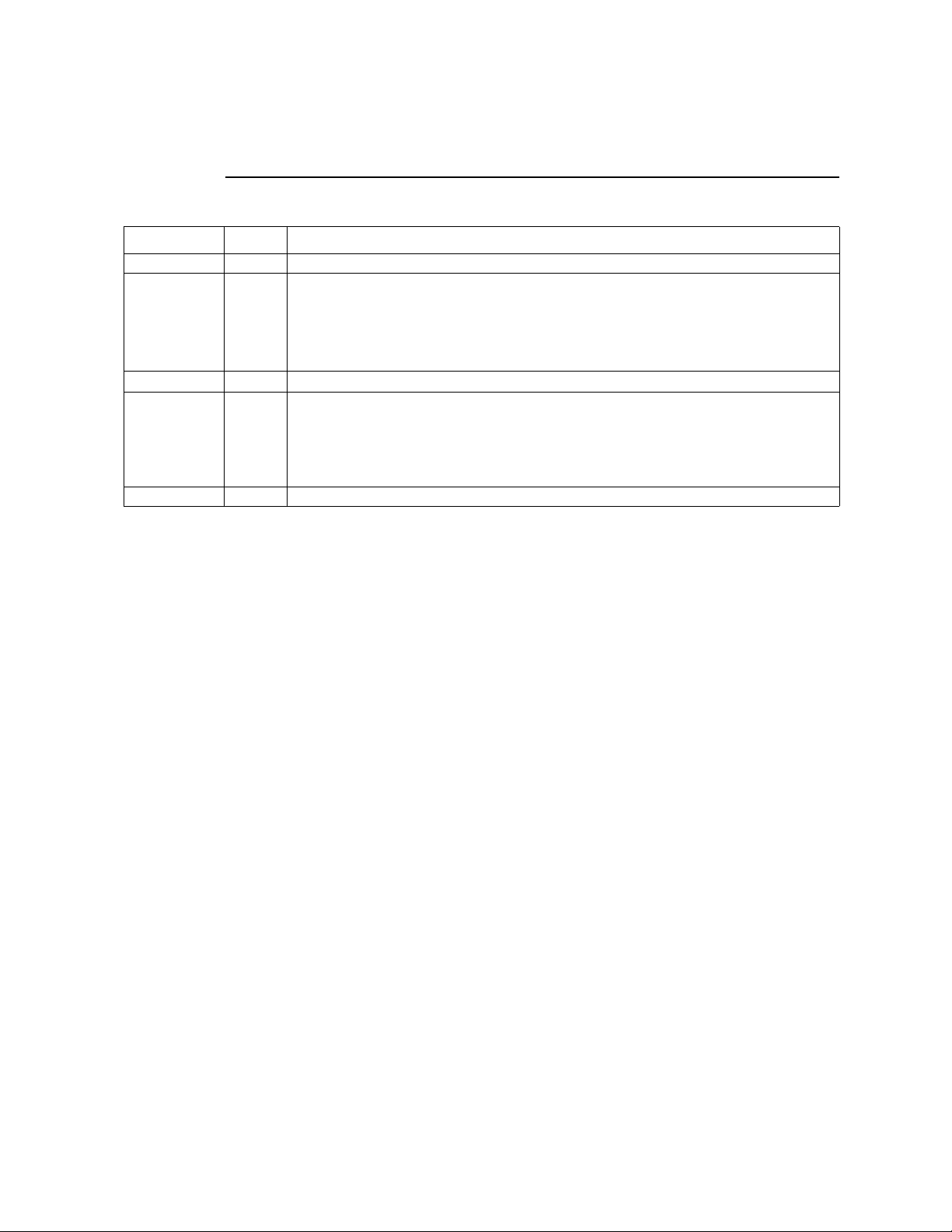
Figure 1 shows the Kontron Carrier Grade Server TIGW1U.
Figure 1. Kontron Carrier Grade Server TIGW1U
Tab le 1 summarizes the major features of the server system.
Table 1. Kontron Carrier Grade Server TIGW1U Features
Feature Description
Compact, high-density
system
Configuration flexibility
Serviceability
December 2009 Product Guide, rev. 1.3
Rack-mount server with a height of 1U (1.75 inches) and a depth of 20.0 inches
Two-way capability in low profile and cost/value-effective packaging
Stand-alone system
Support for two processors: Dual-Core Intel
Quad-Core Intel
Note: Quad-Core Intel
TIGW1U server systems that have product codes TMRA0201W and TMRD0201W.
Rear access to hot-swappable power supplies
Front access to hot-swappable disk drives
®
Xeon® processor 5400 Series
®
Xeon® processor 5400 series support is available only on
®
Xeon® processor 5100 Series or
Kontron Carrier Grade Server TIGW1U
13
Page 14

Table 1. Kontron Carrier Grade Server TIGW1U Features (Continued)
Feature Description
Two hot-swappable 450 W power supplies in a redundant (1+1) configuration
Integrated support for software RAID levels 0 and 1 using three internal hot-
swappable 2.5-inch SAS disk drives and RAID levels 0, 1, and 10 when using
Availability
Manageability
Upgradeability and
investment protection
System-level scalability
Front panel
I/O
additional external SAS drive(s) through rear-panel connector.
Supports ROMB (RAID On Mother Board) hardware RAID operation for RAID 5
capability with addition of optional Intel
DIMM.
®
RAID Activation Key and ECC Mini-
Memory rank sparing
Remote management and diagnostics support
Emergency management port (serial and LAN)
IPMI 2.0-compliant
Support for optional SMART Embedded USB Solid-State Drive
Supports two processors from the Dual-Core Intel
or from the Quad-Core Intel
Note: Quad-Core Intel
TIGW1U server systems that have product codes TMRA0201W and
TMRD0201W.Multi-generational chassis
Supports Intel
Supports 24 Gbyte DDR2-533 or DDR2-667 MHz Registered SDRAM FBD DIMM
memory
Two sockets for Dual-Core Intel
®
Intel
Note: Quad-Core Intel
TIGW1U server systems that have product codes TMRA0201W and
TMRD0201W.Full-height, full-length, 64-bit x 100/66 MHz PCI-X or x8 PCI
Express slot
®
64 architecture
Xeon® processor 5400 Series
®
Xeon® processor 5400 Series
®
Xeon® processor 5400 series support is available only on
®
Xeon® processor 5100 Series or Quad-Core
®
Xeon® processor 5400 series support is available only on
Three internal hot-swappable 2.5-inch hard disk drives
Supports up to four external SAS hard disk drives
Low profile optical drive
Power switch
Reset switch
NMI switch
ID switch
Main power LED
HDD activity LED
Front Access:
• Serial B port (RJ45)
•USB port
NIC activity LED
ID LED
Telco power alarm fault LED/relay
Telco critical alarm fault LED/relay
Telco major alarm fault LED/relay
Telco minor alarm fault LED/relay
Rear Access:
• Dual PS/2 ports for keyboard and
mouse
• Serial B port (RJ45)
•Two USB ports
• Four GbE ports
• 100 Mb RMM management port
• SAS 4x drive port with RAID
support
•Video port
• Telco alarms port
TIGW1U server—Features
®
Xeon® processor 5100 Series
Kontron Carrier Grade Server TIGW1U
Product Guide, rev. 1.3 December 2009
14
Page 15
Features—TIGW1U server
2.1 Server Components
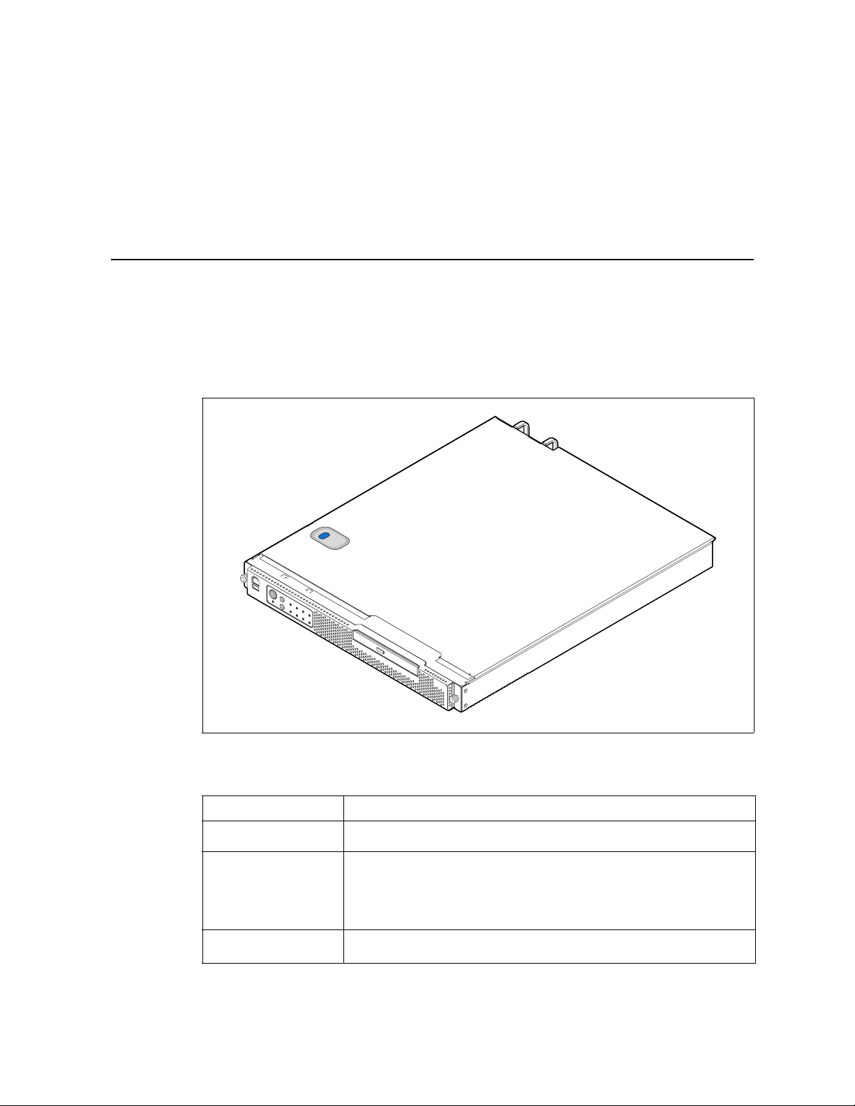
Figure 2 shows the internal components of the TIGW1U server (top cover and front
bezel removed).
Figure 2. Carrier Grade Server TIGW1U Components
C
B
A
D
E
F
M
L
K
J
I
Item Description Item Description
A SAS front panel (SFP) board H System fans
B Power distribution board (PDB) I SAS hard disk drive bays
C Power supplies (AC or DC) J Optical drive
D PCI card bracket (full-length) K
E Riser card assembly L Front panel LEDs and switches
F Server board M
G System memory
SMART Embedded USB Solid-State Drive
(optional)
Front panel serial port (COM2 / Serial B),
USB connector
G
H
AF000801
December 2009 Product Guide, rev. 1.3
Kontron Carrier Grade Server TIGW1U
15
Page 16
TIGW1U server—Features
AF000813
A
R Q P N M L KO
B C D E F G H I J
AF000806
A
D
B C
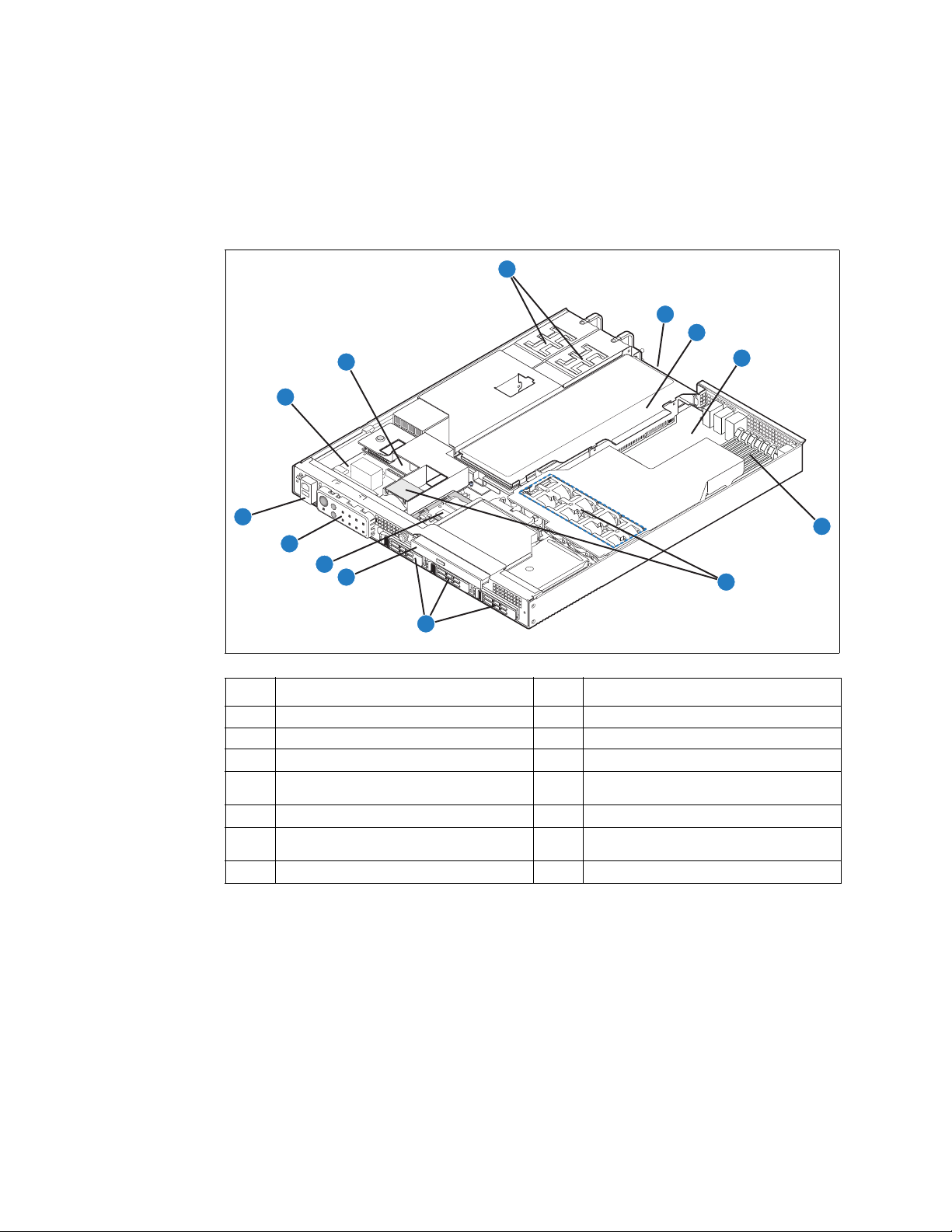
2.2 Back Panel
Note: Figure 3 shows the AC input power configuration. Items G to J can also be configured
for DC operation.
Figure 3. Rear View
Item Description Item Description
A PS/2 mouse J AC power socket
B RJ45 serial port (COM2/Serial B) K External x4 SAS connector
®
Intel
C RJ45 NIC connector L
D RJ45 NIC connector M RJ45 NIC connector
E PCI add-in card bracket or filler panel N RJ45 NIC connector
F Ground studs for DC input (2) O USB port 0 and USB port 1
G Power supply #1 P Telco alarms connector
H AC power connection Q Video connector
I Power supply #2 R Keyboard connector
Remote Management Module 2
®
RMM2) connector (optional)
(Intel
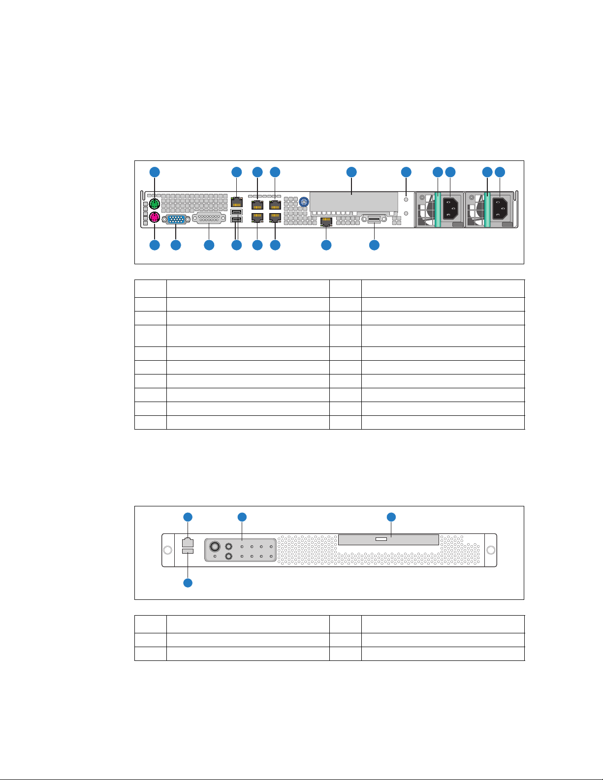
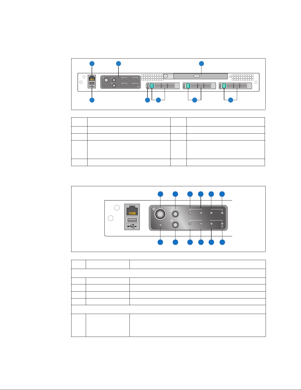
2.3 Front Panel
Figure 4. Front View (Bezel Installed)
Item Description Item Description
A RJ45 serial port (COM2/Serial B) C Optical drive
B Control panels D USB port 2
Kontron Carrier Grade Server TIGW1U
Product Guide, rev. 1.3 December 2009
16
Page 17
Features—TIGW1U server
AF000807
A
H G
C
F
E
D
Alarms
Status
ID ONNIC
CRT MNR PWRMJR
B
Figure 5. Front View (Bezel Removed)
Item Description Item Description
A RJ45 serial port (COM2/Serial B) E Drive bay 1 and handle
B Front panel control switches and LEDs F Drive bay 2 and handle
C Optical drive G
D Drive bay 0 and handle H USB port 2
HDD LEDs
top = fault (amber)
bottom = activity (ready/green;
active/blinking green)
Figure 6. Control Panel
Item Feature Description
A Power switch Toggles the system power
B Reset switch Resets the system
K ID switch Toggles the system ID LED
L NMI switch Asserts NMI to the server board
C Critical (amber)
A
B
C
CRT MNR PWRMJR
ID ONNIC
D
E F
Alarms
Status
L GHIJK
AF000808
Front Panel Switches
Front Panel Alarm LEDs and Relays
When continuously lit, this indicates a Critical System Fault. A critical system
fault is an error or event with a fatal impact to the system. In this case, the
system cannot continue to operate. An example is the loss of a large section
of memory, or other corruption, that renders the system non-operational.
The front panel critical alarm relay engages.
December 2009 Product Guide, rev. 1.3
Kontron Carrier Grade Server TIGW1U
17
Page 18
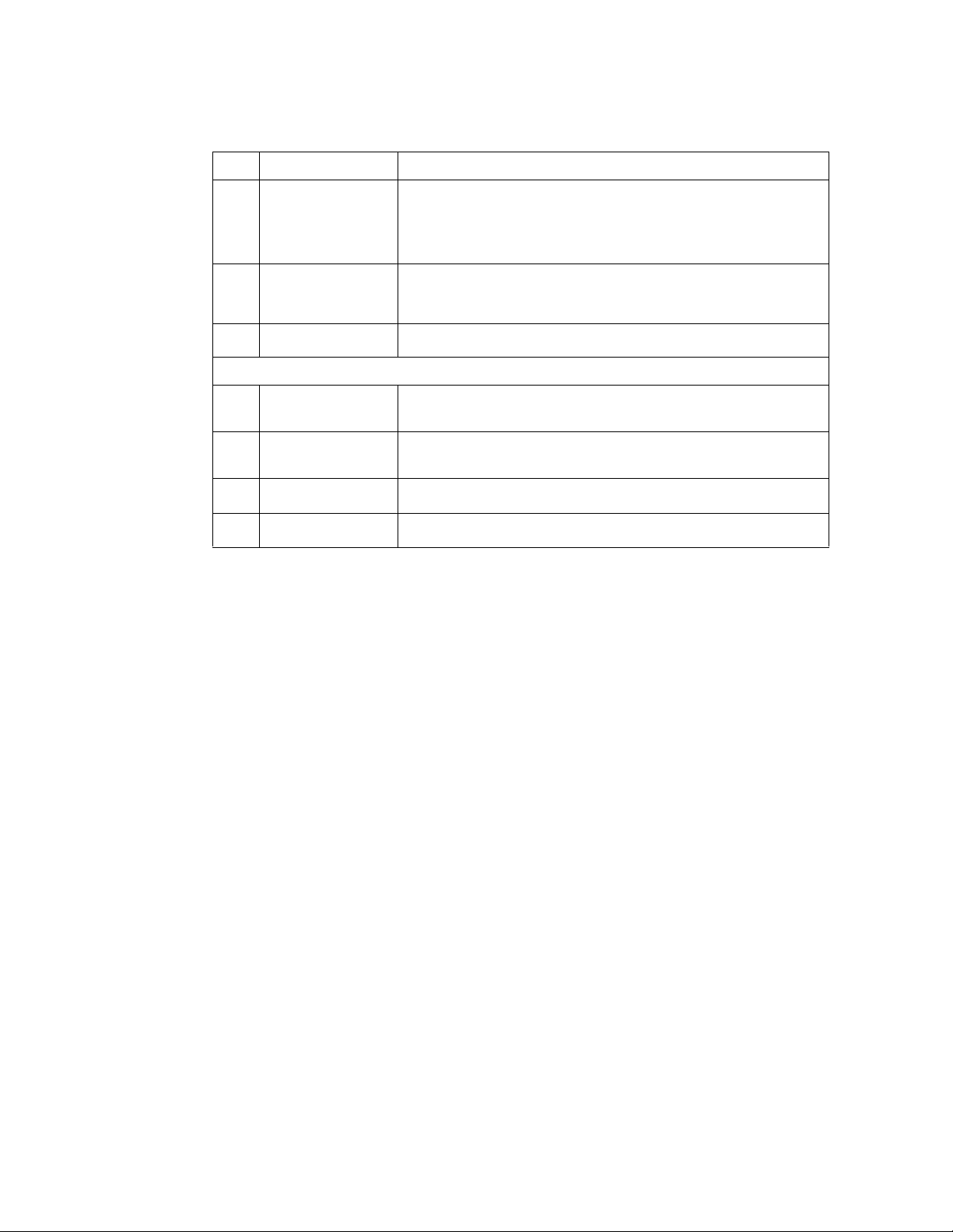
Item Feature Description
When continuously lit, it indicates a Major System Fault. A major system
fault is an error or event that has discernable impact to system operation. In
DMajor (amber)
E Minor (amber)
F Power (amber)
Disk activity/fault LED
G
(green/amber)
Main power LED
H
(green)
NIC activity LED
I
(green)
J System ID LED (white)
this case, the system can continue to operate but in a “degraded” fashion
(reduced performance or loss of non-fatal feature reduction). An example is
the loss of one of two mirrored disks. The front panel major alarm relay
engages.
When continuously lit, it indicates a Minor System Fault. A minor system
fault is an error or event that is detected by the system but likely has little
impact to system operation. An example is a correctable ECC error. The front
panel minor alarm relay engages.
When continuously lit, it indicates a Power System Fault. The front panel
power alarm relay engages.
Front Panel Status LEDs
Indicates SAS hard drive activity when blinking green, or a disk SAS hard
drive fault when amber. See the SAS HDD LEDs to determine specific drive
activity or fault.
When continuously lit, it indicates the presence of DC power in the server.
The LED goes out when the power is turned off or the power source is
disrupted.
Indicates NIC activity
Indicates system identity. THis LED can be toggled remotely or by frontpanel ID switch for identification purposes
TIGW1U server—Features
2.4 Rear Panel Ethernet Ports
The server has four GbE NIC ports mounted on the server board. These ports are
accessible from the rear of the chassis. Copper and fiber options are available. An
additional set of four rear-accessible GbE NIC ports can be added by using an x4 GbE
NIC PCI Express* (PCIe*) or PCI-X* card with rear I/O panel access ports. There are no
GbE NIC ports accessible from the front of the TIGW1U server.
The GbE NIC ports are intended to be installed with shielded cabling that is grounded at
both ends of the cable.
Warning: The intra-building port(s) of the equipment or subassembly is suitable for connection to
intra-building or unexposed wiring or cabling only. The intra-building port(s) of the
equipment or subassembly MUST NOT be metallically connected to interfaces that
connect to the OSP or its wiring. These interfaces are designed for use as intra-building
interfaces only (Type 2 or Type 4 ports as described in GR-1089-CORE, Issue 4) and
require isolation from the exposed OSP cabling. The addition of Primary Protectors is
not sufficient protection in order to connect these interfaces metallically to OSP wiring.
2.5 SAS Front Panel (SFP) Board
The SAS front panel (SFP) board is located in front of the power supplies and extends
behind the hard drives. The SAS drives connect into the SFP board for power and
signals. The SFP board also provides optical drive and fan power connectors and the
user interface for the system’s front panel.
2.5.1 Front Panel Board Features
The SFP board has the following features:
• Four switches to control power-on, reset, NMI, and the system ID LED
• Four alarm relay and power relay LEDs
Kontron Carrier Grade Server TIGW1U
Product Guide, rev. 1.3 December 2009
18
Page 19
Features—TIGW1U server
AF000765
DE G H I LKJFA BC
R PQS
M
N
BB
DD
T
O
V
X
W
U
Y
Z
AA
CC
• One system ID LED that can be controlled remotely or by the system ID switch
• Two system activity LEDs that indicate power-on and NIC activity
• One hard drive activity LED that indicates fault status for drives 0 and 1
• Three hot-swappable SAS hard drives
• Connectors on the SFP board for interfacing to the server board and fans
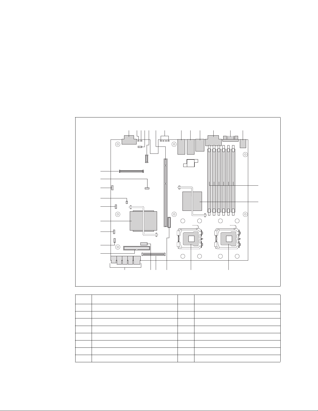
2.6 Server Board Connector and Component Locations
Figure 7. Server Board Connector and Component Locations
Item Description Item Description
A SAS connector P CPU #2 socket
B System identification LED (blue) Q CPU #1 socket
C Systen status LED (green/amber) R CMOS battery
D Serial Port B DSR/DCD jumper (J2A2) S Flex connector to front panel board
December 2009 Product Guide, rev. 1.3
E RMM NIC connector T Serial Port A header
F PCI Express/PCI-X riser card super slot U Main power connector
G POST code diagnotic LEDs V PATA (IDE) connector
H Dual-port LAN connector W Password clear jumper (J1H2)
Kontron Carrier Grade Server TIGW1U
19
Page 20
Item Description Item Description
I Dual-port LAN connector X BIOS Bank Select jumper (J1G1)
J Dual USB 2.0/RJ45 serial port B connector Y Intel
K Telco alarms connector Z CMOS Clear jumper (J1F1)
L Video connector AA BMC Force Update jumper (J1E3)
M PS/2 keyboard and mouse connector BB 3-Pin IPMB header
N FBDIMM slots CC Processor select jumper
OIntel
®
500P Memory Controller Hub (MCH) DD
2.7 Hard Disk Drives
The TIGW1U server chassis provides three hot-swappable hard drive tray assemblies at
the front of the chassis.
For information on how to install these drives, see Section 3.3.1, “Installing or
Replacing a Hard Drive”.
TIGW1U server—Features
®
ESB2-E I/O controller hub
®
Intel
Remote Management Module 2
®
(Intel
RMM2) connector
Note: The TIGW1U server does not support all SAS hard drives. For a list of validated hard
drive manufacturers and hard drive types, see the Tested Hardware and Operating
Systems List (THOL) on the Kontron support website at
http://us.kontron.com/support/.
(Search for TIGW1U, click on Product Downloads, and then Compatability Matrix.)
Each drive can consume up to 17 W of power. Drives must be specified to run at a
maximum ambient temperature of 45° C.
2.8 Riser Card Assembly
The TIGW1U server default riser card assembly contains a PCI-X riser card. There is
also a PCI Express (PCIe) version available as a separately orderable accessory.
The S5000PHB server board implements a PCI super slot that contains the signals
necessary for a PCI/PCI-X or PCIe expansion slot. One of two different low-profile riser
cards is inserted into the super slot to access the appropriate signals and provide the
appropriate connector for a PCI/PCI-X or PCIe riser card. (See Figure 7 for this
location.) The Carrier Grade Server TIGW1U is designed to accommodate full-length,
full-height PCI add-in cards with the card’s I/O bracket accessible through an opening
in the rear panel of the system.
The PCI/PCI-X riser card supports speeds of 33 or 66 MHz PCI and 100 or 133 MHz
PCI-X.
The PCIe riser card implements a x8 link interface, and can be used with add-in cards
that implement x1, x4, or x8 interfaces.
See Section 3.4.5, “Installing or Replacing a PCI Add-in Card” for how to install a PCI
add-in card or how to replace the default PCI-X riser card assembly with a PCIe version.
2.8.1 PCI/PCI-X Riser Card
The PCI/PCI-X riser card, which is the default riser card installed in the assembly,
supports one 3.3 V 64-bit slot and speeds of 33 or 66 MHz for PCI and 66, 100, or
133 MHz for PCI-X. The bus speed varies from 66 MHz to 100 MHz depending on the
Kontron Carrier Grade Server TIGW1U
Product Guide, rev. 1.3 December 2009
20
Page 21
Features—TIGW1U server
Front Panel
Board Area
Airflow
PCI Area
Airflow
CPU-Memory-
HDD Area
Airflow
TS000216
type of PCI add-in card configured in the PCI-X riser card. For detailed information
about the pinouts and electrical specifications, see the Kontron Carrier Grade Server
TIGW1U Technical Product Specification.
2.8.2 PCI Express Riser Card
The PCI Express (PCIe) riser card implements a x8 link interface and can be used with
add-in cards with a x1, x4, or x8 interface. For detailed information about the pinouts
and electrical specifications, see the Kontron Carrier Grade Server TIGW1U Technical
Product Specification.
2.9 Power Supply
The power subsystem has up to two power supply modules capable of operating in
redundant mode and a power distribution board (PDB). A power supply filler panel for
the empty power supply site is supplied for systems without redundancy.
The power supply is rated for 450 W output capability in full AC (or DC) input voltage
range.
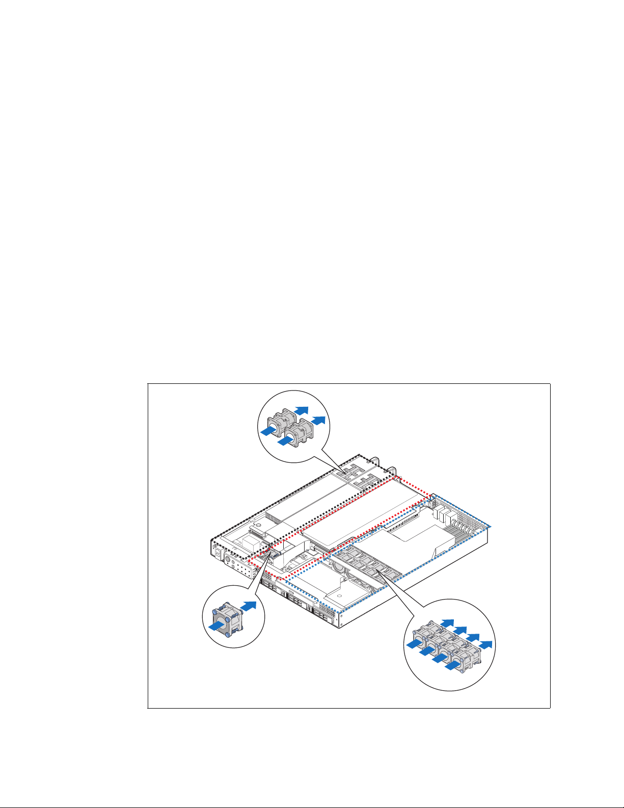
2.10 System Cooling
There are three cooling areas in the TIGW1U server: front panel board area, PCI area,
and CPU-memory-HDD area.
Figure 8. Cooling Areas
December 2009 Product Guide, rev. 1.3
Kontron Carrier Grade Server TIGW1U
21
Page 22

2.10.1 Front Panel Cooling Area
The left one-fourth of the SFP board and the portion of the power distribution board
(PDB) in this area are cooled by 40 x 40 x 56 mm PSU dual-rotor fans. One PSU fan is
sufficient to cool this portion of the front panel board area and two PSU fans provide
cooling redundancy for this area.
PSU fans draw air in through the front bezel and from vents in the left front side of the
chassis. The air is exhausted out the rear of the PSUs. The left wall of the PCI fan air
duct and the PSU guide wall provide an air flow barrier between the front panel board
cooling area and the PCI cooling area.
2.10.2 PCI Cooling Area
The 40 x 40 x 28 mm single-rotor PCI fan cools the portions of the server board, PDB,
and SFP that are in this area as well as a PCI add-in card installed in the riser card
assembly.
The PCI fan draws in air is through the front bezel and exhausts through the rear of the
system. A plastic air duct directs the air flow in this area, houses the PCI fan, and
provides air flow barriers between:
• The front panel board and the PCI cooling areas
• The PCI and the CPU / memory / HDD cooling areas
TIGW1U server—Features
A second plastic part behind the PCI air duct continues the air flow barrier between the
PCI cooling area and the CPU / memory / HDD cooling area. The riser card provides the
third portion of the air flow barrier between the PCI cooling area and the CPU / memory
/ HDD cooling area.
2.10.3 CPU / Memory / HDD Cooling Area
The server uses four 40 x 40 x 56 mm dual-rotor fans that are assembled in a sheet
metal bracket attached to the chassis.
The server draws air in through the front bezel and exhausts it out the rear of the
chassis. The CPU / memory / HDD cooling area air flow path is isolated from the rest of
the system by an air duct and riser card. Air entering the CPU / memory air duct is
preheated by the hard drives.
2.11 Hardware Requirements
To avoid integration difficulties and possible board damage, your system must meet the
requirements outlined in the subsections below. For a list of qualified components, see
Section 1.4, “Additional Information and Software”.
2.11.1 Processor
The S5000PHB server boardaccommodates two Dual-Core Intel® Xeon® processor
5100 Series or two Quad-Core Intel
2.11.2 Memory
®
Xeon® processor 5400 series.
The S5000PHB server board supports up to six DDR2-533 or DDR2-667 Fully Buffered
DIMMs (FBD memory) in six DIMM slots across two channels, Channel 0 and Channel 1.
Channel 0 consists of DIMM sockets A1, A2, and A3. Channel 1 consists of DIMM
sockets B1, B2, and B3. See Section 3.4.2, “Configuring Memory DIMMs” on page 34
for population rules and configuration information.
Kontron Carrier Grade Server TIGW1U
Product Guide, rev. 1.3 December 2009
22
Page 23

Server Installations and Upgrades—TIGW1U server
3 Server Installations and Upgrades
3.1 Before You Begin
Before working with your server product, pay close attention to the safety instructions
provided in this manual. See Appendix A, “Safety Information”.
Warning: Electrostatic discharge (ESD) and ESD protection: ESD can damage disk drives,
boards, and other parts. We recommend that you perform all procedures in this chapter
only at an ESD workstation. If an ESD workstation is not available, provide some ESD
protection by wearing an antistatic wrist strap attached to chassis ground (any
unpainted metal surface) on your server when handling parts.
3.1.1 Tools and Supplies Needed
• Phillips* (cross-point) screwdriver (#1 bit and #2 bit)
• Anti-static wrist strap and conductive foam pad
3.1.2 System References
All references to left, right, front, top, and bottom assume that you are facing the front
of the server, as it would be positioned for normal operation.
3.1.3 Cable Routing Reference
It is important for cables to be connected correctly. See Figure 9. For more detailed
information about cable connectors, see the Kontron Carrier Grade Server TIGW1U
Technical Product Specification.
December 2009 Product Guide, rev. 1.3
Kontron Carrier Grade Server TIGW1U
23
Page 24

Figure 9. TIGW1U server System Cable Routing
TIGW1U server—Server Installations and Upgrades
3.2 General Installation Procedures
The following sections present general installation and removal procedures that are
required before removing or installing non-hot-swappable internal components.
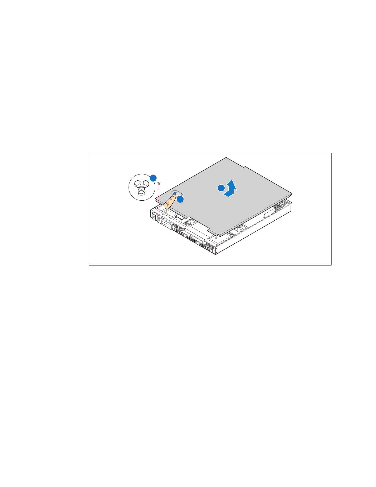
3.2.1 Removing the Chassis Cover
The TIGW1U server must be operated with the top cover in place to ensure proper
cooling. You need to remove the top cover to add or replace components inside of the
server. Before removing the top cover, power down the server system and unplug all
peripheral devices and the power cable.
Kontron Carrier Grade Server TIGW1U
Product Guide, rev. 1.3 December 2009
24
Page 25
Server Installations and Upgrades—TIGW1U server
A
B
C
TS000201
Note: A non-skid surface or a stop behind the server may be needed to prevent the server
from sliding on your work surface.
1. Observe the safety and ESD precautions in Appendix A, “Safety Information”.
2. Turn off all peripheral devices connected to the server. Turn off the server.
3. Disconnect the power cord.
4. Remove the shipping screw from the front of the chassis on the left side (“A”), if
present.
5. While pressing down the blue button at the top of the chassis (“B”), slide the top
cover back until it stops. (“C”).
6. Lift the cover straight up to remove it. (“C”)
Figure 10. Removing the Chassis Cover
3.2.2 Installing the Chassis Cover
1. Place the cover over the chassis so that the side edges of the cover sit just inside
the chassis sidewalls, with the front of the cover with about a 1/8-inch (3-mm) gap
between the chassis cover and the sheet-metal at the front of the chassis.
2. Press down slightly on the chassis cover behind the peripheral area and slide the
cover forward until it clicks into place.
3. (Optional) Install the shipping screw.
4. Reconnect all peripheral devices and the power cord.
Caution: This unit must be operated with the top cover installed to ensure proper cooling.
3.2.3 Removing the Front Bezel
Note: Hold the bezel in place while you loosen the screws. After both screws are loosened,
the bezel drops from the chassis.
1. Remove the left-side screw. (“A” in Figure 11)
2. Remove the right-side screw to release the bezel.
December 2009 Product Guide, rev. 1.3
Kontron Carrier Grade Server TIGW1U
25
Page 26
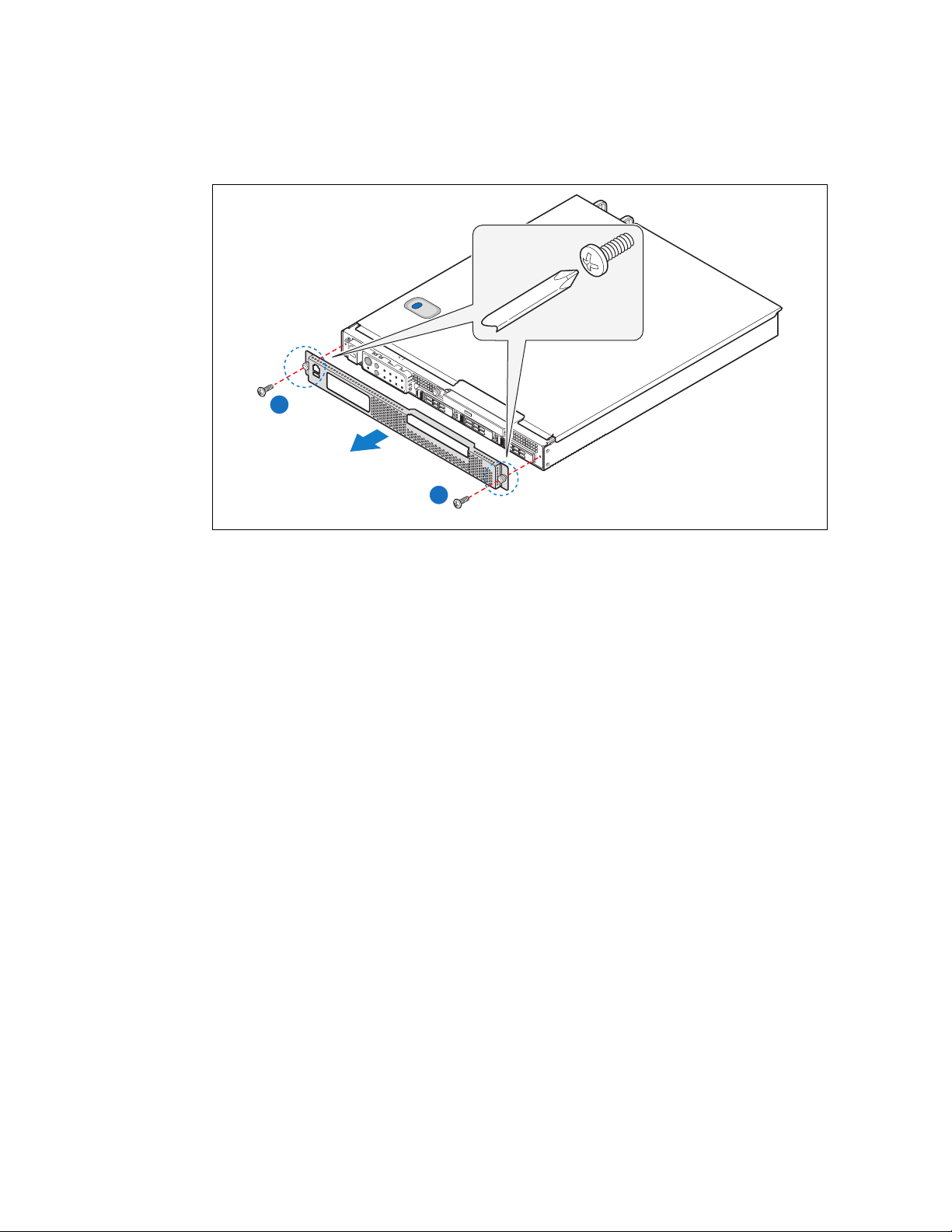
Figure 11. Removing the Front Bezel
A
TIGW1U server—Server Installations and Upgrades
A
TS000202
3.2.4 Installing the Front Bezel
While holding the front bezel in place, tighten the captive screws at the left and right
edges of the bezel.
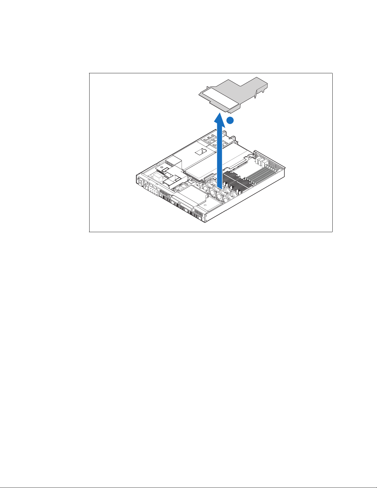
3.2.5 Removing the Processor Air Duct
The air duct must be removed to access the processors, memory DIMMs, and the fourfan assembly. The processor air duct is required for proper airflow within the chassis.
Be sure the air duct is in place before installing the chassis cover. To remove the
processor air duct:
1. Power down the server system and unplug all peripheral devices and the AC power
cable.
2. Remove the chassis cover. For instructions, see Section 3.2.1, “Removing the
Chassis Cover” on page 24.
3. Lift the air duct straight up and lift it from the chassis (“A” in Figure 12).
Kontron Carrier Grade Server TIGW1U
Product Guide, rev. 1.3 December 2009
26
Page 27
Server Installations and Upgrades—TIGW1U server
TS000203
A
Figure 12. Removing the Air Duct
3.2.6 Installing the Processor Air Duct
1. Place the processor air duct over the processor sockets and four-fan assembly,
using caution to make sure you do not pinch any wires beneath the edges of the air
duct.
The top of the installed air duct should be flush with the top surface of the PCI riser
card assembly.
2. Replace the chassis cover if you have completed all work inside of the chassis.
3.3 Hot-Swappable Component Installation Procedures
The following components are hot-swappable and do not require powering down the
system or removing the chassis cover:
• Hard disk drives
• AC and DC power supplies
3.3.1 Installing or Replacing a Hard Drive
Up to three hot-swappable drives can be installed in your TIGW1U server. You must
remove the front bezel to add or replace a hard drive.
Caution: If you install fewer than three hard drives, the empty bays must be populated with
drive trays that have baffles in them to maintain proper system cooling.
The Carrier Grade Server TIGW1U does not support all SAS hard drives. To see a list of
validated manufacturers and hard drive types, go to:
http://us.kontron.com/support/
Search for TIGW1U, click on Product Downloads, and then select Compatibility Matrix.
December 2009 Product Guide, rev. 1.3
Kontron Carrier Grade Server TIGW1U
27
Page 28
TIGW1U server—Server Installations and Upgrades
A
TS000218
TS000219
A
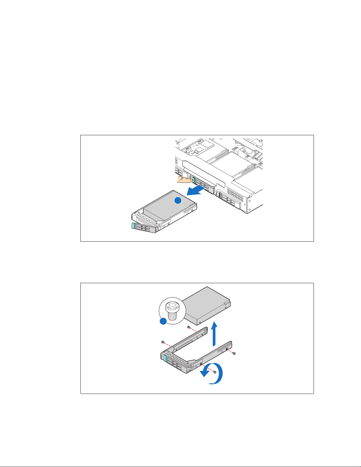
3.3.1.1 Removing a Hard Drive Tray from the Chassis
1. Remove the front bezel. For instructions, see Section 3.2.3, “Removing the Front
Bezel” on page 25.
2. Select the drive bay where you want to install the drive. Remove the drive tray by
pressing the green button to open the lever.
Note: If you will have fewer than three drives installed, drive bay 0 must be used first, then
drive bay 1.
3. Pull the drive tray assembly out of the chassis. (“A” in Figure 13)
Figure 13. Removing a Drive Tray from the Chassis
3.3.1.2 Attaching a Hard Drive to the Drive Tray
1. If a drive is already installed (that is, if you are replacing the drive), remove it by
unfastening the four screws that attach it to the drive tray. (“A” in Figure 14)
Figure 14. Removing a Disk Drive from the Drive Tray
Kontron Carrier Grade Server TIGW1U
Product Guide, rev. 1.3 December 2009
28
Page 29
Server Installations and Upgrades—TIGW1U server
AF000810
A
B
AF000809
A
C
B
D
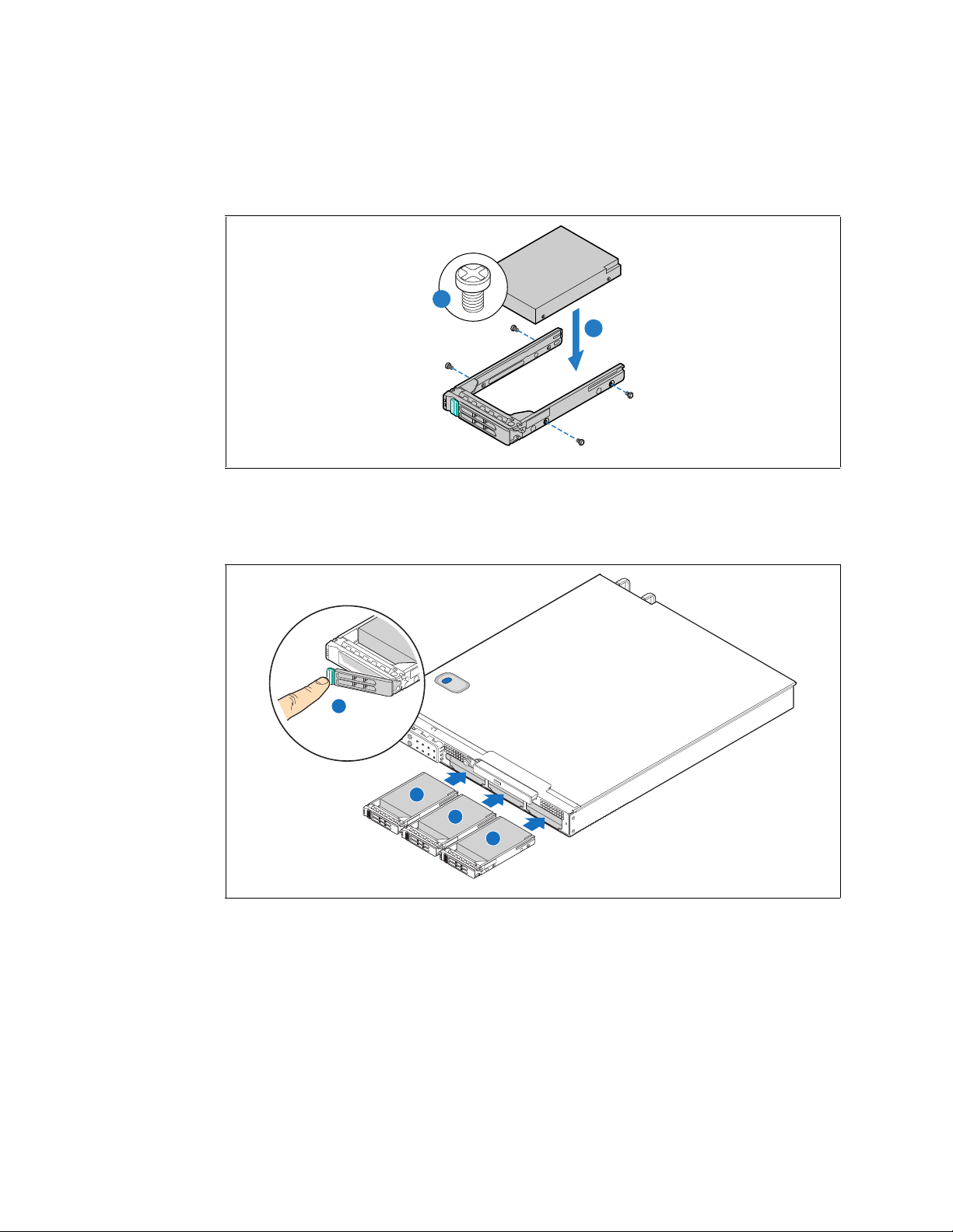
2. Install the new drive in the drive tray and secure the drive with the four screws that
come with the drive tray. (“A” and “B” in Figure 15)
Figure 15. Installing a Hard Drive
3. With the drive tray locking lever fully open, push the hard drive tray into the drive
bay in the chassis until it stops. (“A”, “B” and “C” in Figure 16)
4. Press the lever until it snaps shut to close the drive in the bay. (“D”)
Figure 16. Inserting a New Drive Assembly into the Chassis
5. Replace the front bezel.
3.3.2 Replacing a Power Supply Module
Caution: Your server does not have a redundant power supply unless you have purchased the
optional second power supply module. If there is no second supply, before replacing the
power supply you must first take the server out of service, turn off all peripheral
devices connected to the system, turn off the system by pressing the power button,
and unplug the power cord from the system or wall outlet.
December 2009 Product Guide, rev. 1.3
Kontron Carrier Grade Server TIGW1U
29
Page 30
TIGW1U server—Server Installations and Upgrades
DC PS
AC PS
TS000204
A
B
B
C
D
To maintain hot-swap capability, make sure an active power supply module is in each
chassis slot before replacing (hot-swapping) a power supply module.
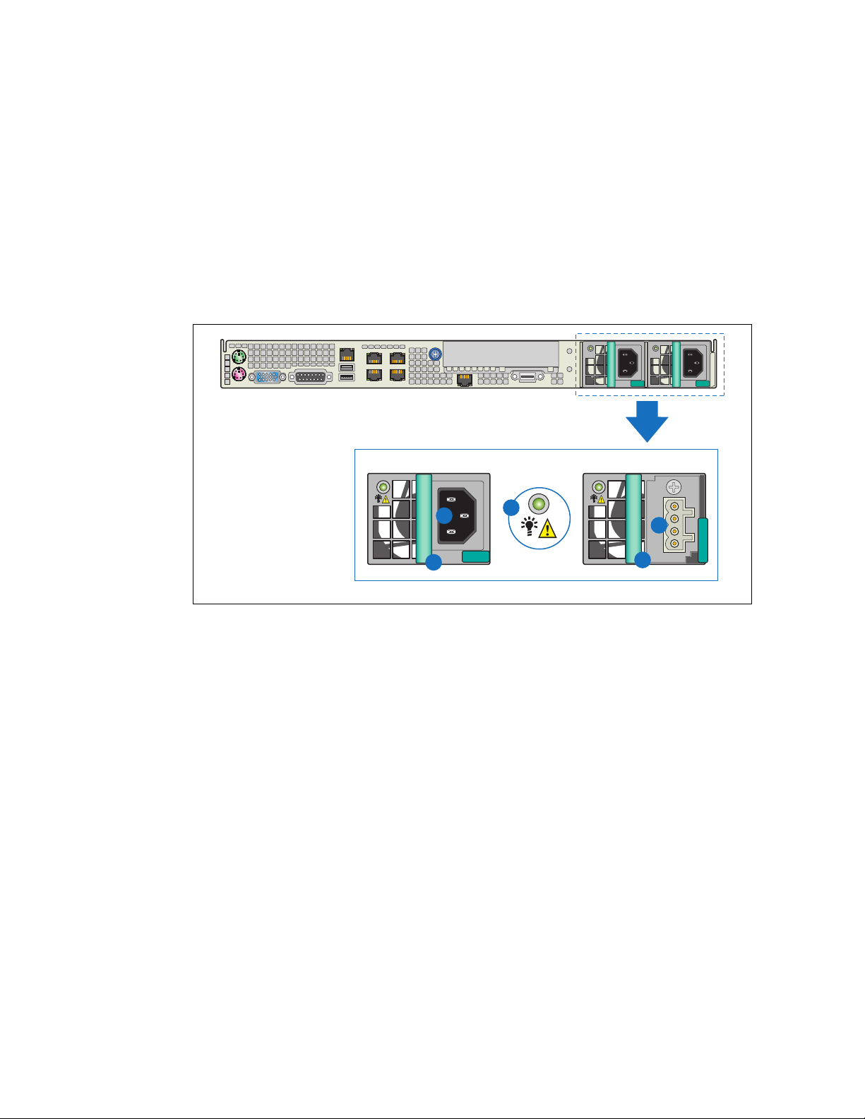
3.3.2.1 Removing the Power Supply Module
1. Check the status LED to determine which power supply has failed (“A” in
Figure 17). Disconnect the appropriate power cable.
2. Press and hold the green safety lock to the left to disengage the power supply
module.
3. Grasp the handle and pull the power supply from the chassis. (“B”)
Figure 17. AC and DC Power Supplies
3.3.2.2 Installing the Power Supply Module
Press and hold the green safety lock to the left and slide the power supply module into
the chassis slot.
3.3.2.3 Grounding a DC-Powered System
The DC chassis provides two #10-32 threaded studs for chassis enclosure grounding.
A single 90º standard barrel, two-hole, compression terminal lug with 5/8-inch pitch
suitable for #14-10 AWG conductor (such as the Thomas & Betts* terminal lug p/n
256-31426-141) must be used for proper safety grounding. See “D” in Figure 3, “Rear
View” on page 16 for the location of the ground studs.
A crimping tool may be needed to secure the terminal lug to the grounding cable.
3.4 Internal System Component Installation Procedures
Note: The procedures in this section assume that you have powered down the server and
removed the chassis cover as described in Section 3.2, “General Installation
Procedures” on page 24.
Kontron Carrier Grade Server TIGW1U
Product Guide, rev. 1.3 December 2009
30
Page 31

Server Installations and Upgrades—TIGW1U server
3.4.1 Configuring Jumpers on the Server Board
The jumpers are located on the S5000PHB server board server board, which is in the
rear left side of the TIGW1U server chassis. To configure the jumpers on the server
board, in adddition to removing the chassis cover, you also must remove the processor
air duct (see Section 3.2.5, “Removing the Processor Air Duct” on page 26) and the PCI
riser card assembly (see Section 3.4.5.1, “Removing the PCI Riser Card Assembly” on
page 42). All other components installed on the server board can remain in place.
The jumpers that can be configured are:
• J2A2 (Serial Port B DSR/DCD jumper)
• J1H2 (Password Clear jumper)
• J1G1 (BIOS Bank Select jumper)
• J1F1 (CMOS Clear jumper)
• J1E3 (BMC Force Update jumper)
• J3E2 (Processor select jumper)
See Figure 7 for the location of these jumpers. The following sections give more
detailed information about the settings.
3.4.1.1 Jumper Blocks
The server board has several 2-pin and 3-pin jumper blocks (see Figure 7) that can be
used to configure, protect, or recover specific features of the server board. Pin 1 on
each jumper block is denoted by an “*” or “ ”. Ta bl e 2 describes the function of each
recovery jumper on the server board.
Table 2. Jumpers
Jumper Name Pins What happens at system reset…
J1E3: BMC Force
Update
J1H2: Password
Clear
J1G1: Bank Select
J1F1: CMOS Clear
J3E2: Processor
Note: Bold entry in “Pins” column indicates default configuration.
No Jumper BMC Firmware Force Update Mode – Disabled (Default)
Jumper BMC Firmware Force Update Mode – Enabled
1-2
2-3
1-2 Force to lower flash bank during boot-up
2-3 Normal operation/use primary flash bank (Default)
1-2
2-3
1-2
No Jumper
These pins should have a jumper in place for normal system operation.
(Default)
If these pins are jumpered, administrator and user passwords will be
cleared on the next reset. These pins should not be jumpered for normal
operation.
These pins should have a jumper in place for normal system operation.
(Default)
If these pins are jumpered, the CMOS settings will be cleared on the next
reset. These pins should not be jumpered for normal operation
If these pins are jumpered, the system is configured for a Dual-Core
®
Intel
Xeon® processors 5100 series. (Default)
Caution: Pins 2-3 should never be jumpered. The system will not function
correctly if these pins are jumpered.
If no pins are jumpered, the system is configured for a Quad-Core Intel
®
processors 5400 series.
Xeon
®
December 2009 Product Guide, rev. 1.3
Kontron Carrier Grade Server TIGW1U
31
Page 32

TIGW1U server—Server Installations and Upgrades
3.4.1.2 CMOS Clear and Password Reset Procedures
The procedure is identical for clearing the CMOS and the password, but has changed
from previous generation server boards. The following steps outline the new procedure
for both operations.
1. Power down the server and remove the power cable. (Standby power is present on
the server board when power is turned off but still connected.)
2. Open the server.
3. Move the jumper link from the default operating position (Pins 1-2) to the Reset/
Clear position (Pins 2-3) on the appropriate jumper (J1F1 for CMOS Clear or J1H2
for Password Reset).
4. Wait 5 seconds.
5. Move the jumper back to the default position (Pins 1-2).
6. Close the server.
7. Reconnect the power source and power up the server.
8. The password and/or CMOS is cleared and can be reset in BIOS setup.
3.4.1.3 BMC Force Update Procedure
When performing a standard BMC firmware update procedure, the update utility places
the BMC into an update mode, allowing the firmware to load safely onto the flash
device. If the BMC firmware update process fails because the BMC was not in the
proper update state, the server board provides a BMC Force Update jumper that forces
the BMC into the proper update state. If the standard BMC firmware update process
fails, the following procedure should be followed:
1. Power down the server and remove the power cable. (Standby power is present on
the server board when power is turned off but still connected.)
2. Open the server.
3. Place a jumper on the J1E3 header.
4. Close the server.
5. Reconnect the power source and power up the server.
6. Perform the BMC firmware update procedure that is documented in the
README.TXT file that is included with the BMC Firmware Update package.
Note: After completing of the firmware update process, the firmware update utility may
generate an error message that states that the BMC is still in update mode.
7. Power down the server and remove the power cable.
8. Open the server.
9. Remove jumper from J1E3.
10. Close the server.
11. Reconnect power source and power up the server.
Note: Normal BMC functionality is disabled when the Force BMC Update jumper is populated.
The server should never be run with the BMC Force Update jumper populated and
should only be used when the standard firmware update process fails. This header
should remain unpopulated by default when the server is running normally.
Kontron Carrier Grade Server TIGW1U
Product Guide, rev. 1.3 December 2009
32
Page 33

Server Installations and Upgrades—TIGW1U server
3.4.1.4 BIOS Select Jumper
The jumper block at J1G1 is used to select which BIOS image the system will boot to.
Pin 1 on the jumper is identified with a “ ”. This jumper should only be moved if you
want to force the BIOS to boot to the secondary bank, which may hold a different
version of the BIOS.
The rolling BIOS feature of the server board automatically alternates the Boot BIOS to
the secondary bank if the BIOS image in the primary bank is corrupted and cannot
boot.
3.4.1.5 Serial B Port Configuration Jumper
The rear of the Carrier Grade Server TIGW1U provides an RJ45 connector for the Serial
B port, which is intended for direct connection to serial devices such as serial port
concentrators using a standard Cat 5 cable.
Serial devices that use RJ45 connectors differ in the signal they require on Pin 7. For
example, modems typically require the DSR signal, and serial concentrators may
require the DCD signal. Tab le 3 describes how to use jumper J2A2 to configure the
serial port to provide either of these two signals.
Table 3. Serial B Port Configuration Jumper
Jumper Name Pins Description of Configuration
1-2
J2A2: Serial Port
2-3
Note: Bold entry in “Pins” column indicates default configuration.
DCD (Data Carrier Detect) signal routed to Pin 7 of rear RJ45 Serial B
port connector. This configuration provides compatibility with Cisco serial
concentrators. (Default)
DSR (Data Set Ready) signal routed to Pin 7 of rear RJ45 Serial B port
connectors. This configuration provides compatibility with standard
modems.
3.4.1.6 Processor Select Jumper
The server board is pre-configured for the Dual-Core Intel® Xeon® processor 5100
series, but the following server system product codes support both the Dual-Core
Intel® Xeon® processor 5100 series and the Quad-Core Intel® Xeon® processor 5400
series. These product codes have an “R in the third position.
• Kontron Carrier Grade Server TIGW1U. AC
• Kontron Carrier Grade Server TIGW1U. DC
If you have one of these products and you want to use a Quad-Core Intel
processor 5400 series, you must remove the jumper from pins 1-2 on the processor
select jumper. This jumper is located at position J3E2 on the server board. See the
following figure.
®
Xeon®
December 2009 Product Guide, rev. 1.3
Kontron Carrier Grade Server TIGW1U
33
Page 34

TIGW1U server—Server Installations and Upgrades
CPU CPU
J3E2
123
123
for Dual-Core Intel®
Xeon
®
Processor
5100 Series:
for Quad-Core Intel
®
Xeon® Processor
5400 Series:
NO jumper
installed.
Install jumper
over pins 1-2.
CAUTION: Jumper J3E2 must be
configured to match your installed
processor or your system will not boot
properly.
Server
Board
Channel 1
Channel 0
DIMM Sockets
DIMM A1
DIMM A2
DIMM B3
DIMM B2
DIMM A3
DIMM B1
AF000879
Regardless of the processor model you install, you must use BIOS version R0085 or
later with any server that has one of the above product codes:
Caution: If your server has one of the above product codes, then configuring it with a BIOS
version lower than R0085 will cause system instabilities and your system may not boot.
3.4.2 Configuring Memory DIMMs
Figure 18. DIMM Slots and Channels
The S5000PHB server board server board supports up to six DDR2-533 or DDR2-667
Fully Buffered DIMMs (FBD memory) in six DIMM slots across two channels, Channel 0
and Channel 1.
Channel 0 consists of DIMM sockets A1, A2, and A3. Channel 1 consists of DIMM
sockets B1, B2, and B3. See Figure 18.
Kontron Carrier Grade Server TIGW1U
Product Guide, rev. 1.3 December 2009
34
Page 35

Server Installations and Upgrades—TIGW1U server
The two channels support registered DDR2-533 and DDR2-667 FBDIMM memory
(stacked or unstacked). Peak theoretical memory data bandwidth is 6.4 Gbytes/s with
DDR2-533 or 8.0 Gbytes/s with DDR2-667.
Tab le 4 and Ta bl e 5 show the maximum memory configurations supported using the
specified memory technology.
Table 4. Maximum 6 DIMM System Memory Configuration - x8 Single Rank
DRAM Technology x8 Single Rank Maximum Capacity
256 Mbit 1.5 Gbytes
512 Mbit 3 Gbytes
1024 Mbit 6 Gbytes
2048 Mbit 12 Gbytes
Table 5. Maximum 6 DIMM System Memory Configuration - x4 Dual Rank
DRAM Technology x4 Dual Rank Maximum Capacity
256 Mbit 6 Gbytes
512 Mbit 12 Gbytes
1024 Mbit 24 Gbytes
2048 Mbit 48 Gbytes
3.4.2.1 DIMM Population Rules
DIMM population rules depend on the operating mode of the memory controller, which
is determined by the number of DIMMs installed. DIMM pairs are populated in the
following DIMM slot order: A1 and B1, A2 and B2, A3 and B3.
DIMMs within a given pair must be identical with respect to size, speed, and
organization, but DIMM capacities can be different between different DIMM pairs. For
example, a valid mixed DIMM configuration may have 512 Mbyte DIMMs installed in
DIMM slots A1 and B1, and 1 Gbyte DIMMs installed in DIMM slots A2 and B2. Single
DIMM operation is supported with the DIMM populated in slot A1 only, but populating in
pairs is recommended.
3.4.2.2 Supported DIMM Configurations
Supported DIMM configurations for this server board are shown in Tab le 6.
Table 6. FBDIMM Population Options
Channel 0 Channel 1
DIMMA1 DIMMA2 DIMMA3 DIMMB1 DIMMB2 DIMMB3
= Slot is populated.
= Slot is not populated.
Sparing
Possible
NO
NO
YES
NO
December 2009 Product Guide, rev. 1.3
Kontron Carrier Grade Server TIGW1U
35
Page 36

TIGW1U server—Server Installations and Upgrades
3.4.2.3 Sparing Mode Memory Configuration
The Memory Controller Hub (MCH) provides memory sparing capabilities. Sparing is a
RAS feature that involves configuring a DIMM to be placed in reserve so it can be use to
replace a DIMM that fails. The following conditions apply:
• DIMMA1 and DIMMB1 must be identical in organization, size and speed.
• DIMMA2 and DIMMB2 must be identical in organization, size and speed.
• DIMMA1 and DIMMA2 need not be identical in organization, size and speed.
• DIMMB1 and DIMMB2 need not be identical in organization, size and speed.
• Sparing should be enabled in the BIOS setup; the BIOS will configure Rank Sparing
Mode.
• The larger of the pairs {DIMMA1, DIMMB1} and {DIMMA2, DIMMB2} will be
selected as the spare pair unit.
3.4.3 Installing and Removing Memory DIMMs
The silkscreen on the board for the DIMMs displays DIMMA1, DIMMA2, DIMMA3,
DIMMB1, DIMMB2 and DIMMB3, starting from the inside (left side) of the server board.
DIMMB3 is the socket closest to the outside edge of the server board.
3.4.3.1 Installing DIMMs
To install DIMMs, follow these steps:
1. Remove the air duct. For instructions, see Section 3.2.5, “Removing the Processor
Air Duct” on page 26.
2. Locate the DIMM sockets on the server board and select the socket where you want
to install the DIMM. (See Figure 9 and Figure 19.)
Figure 19. Installing Memory DIMMs
E
D
A
DIMM A3
DIMM A2
DIMM A1
DIMM B1
DIMM B2
DIMM B3
C
B
Channel 1
Channel 0
TS000224
3. Open both DIMM socket levers. (“A” in Figure 19)
Kontron Carrier Grade Server TIGW1U
Product Guide, rev. 1.3 December 2009
36
Page 37

Server Installations and Upgrades—TIGW1U server
4. Note the location of the alignment notch. (“B”)
5. Insert the DIMM making sure the connector edge of the DIMM aligns correctly with
the slot. (“E”)
6. Using both hands, push down firmly and evenly on the DIMM until it snaps into
place and both levers close. (“C” and “D”)
IMPORTANT: Visually check that each latch is fully closed and correctly engaged
with each DIMM edge socket.
7. Replace the processor air duct and the chassis cover if you have completed all work
inside of the server.
3.4.3.2 Removing DIMMs
To remove or replace a DIMM, follow these steps:
1. Remove the processor air duct. For instructions, see Section 3.2.5, “Removing the
Processor Air Duct” on page 26.
2. Locate the DIMM(s) and select the one to be removed or replaced. See Figure 19.
3. Open the DIMM socket levers.
4. Holding the DIMM by the edges with both hands, lift it away from the socket and
store it in an anti-static package.
5. If you are replacing the DIMM, follow the instructions in Section 3.4.3.1, “Installing
DIMMs” on page 36.
6. Replace the chassis cover if you have completed all work inside of the server.
3.4.4 Adding or Replacing a Processor
Note: Use the instructions below to add or replace a processor instead of using the
Caution: The processor must be appropriate: You could damage the server board if you install a
3.4.4.1 ESD and Handling Processors
instructions that came with the processor.
processor that is inappropriate for your server. Go to http://us.kontron.com/support/
for a list of compatible processors for the TIGW1U server.
• When opening a socket, do not touch the gold socket wires.
• When unpacking a processor, hold it only at the edges to avoid touching the gold
contacts.
• Reduce the risk of electrostatic discharge (ESD) damage to the processor by doing
the following:
— Touch the metal chassis before touching the processor or server board.
— Keep part of your body in contact with the metal chassis to dissipate the static
charge while handling the processor.
— Avoid moving around unnecessarily.
— Use a ground strap attached to the front panel (with the bezel removed.)
December 2009 Product Guide, rev. 1.3
Kontron Carrier Grade Server TIGW1U
37
Page 38

Figure 20. Cautions for Handling Processors
A
B
2
3
1
4
AF000766
Follow the instructions below to remove and then install a processor, referring to
Figure 21 through Figure 27.
3.4.4.2 Removing a Processor
1. Remove the processor air duct that covers the processor. For instructions, Section
3.2.5, “Removing the Processor Air Duct” on page 26.
2. Loosen the four captive screws on the corners of the heat sink (“A” in Figure 21).
3. Twist the heat sink slightly to break the seal between the heat sink and the
processor. (“B”)
4. Lift the heat sink from the processor. If it does not pull up easily, twist the heat sink
again.
TIGW1U server—Server Installations and Upgrades
Note: Do not force the heat sink from the processor. Doing so could damage the processor.
Figure 21. Removing the Heat Sink
5. Open the socket by pushing the lever handle down and away from the socket to
release it. (“A” and “B” in Figure 22)
Kontron Carrier Grade Server TIGW1U
Product Guide, rev. 1.3 December 2009
38
Page 39

Server Installations and Upgrades—TIGW1U server
A
B
AF000768
A
B
AF000769
A
AF000770
Figure 22. Using the Socket Lever
6. Pull the lever and open the load plate all the way. (“A” and “B” in Figure 23)
Figure 23. Opening the Load Plate
7. Remove the processor.
3.4.4.3 Installing a New Processor
To install a processor, follow these instructions:
1. Take the processor out of its packaging and remove the protective shipping cover.
(“A” in Figure 24)
Figure 24. Removing the Processor from its Shipping Cover
December 2009 Product Guide, rev. 1.3
Kontron Carrier Grade Server TIGW1U
39
Page 40

TIGW1U server—Server Installations and Upgrades
A
B
AF000771
B
A
AF000772
Caution: The underside of the processor has components that may damage the socket pins if
installed improperly. The processor must align correctly with the socket. Set the
processor carefully into the socket!
2. Orient the processor with the socket so that the processor cutouts match the
socket notches. (“A” in Figure 25)
3. Insert the processor into the socket. (“B”)
Figure 25. Installing the Processor in the Processor Socket
[
4. Remove the socket protective cover by grasping the cover tab and pulling away
from the load plate. Store the protective cover for future use. (“A” and “B” in
Figure 26)
Figure 26. Removing the Socket Protective Cover
Kontron Carrier Grade Server TIGW1U
Product Guide, rev. 1.3 December 2009
40
Page 41

Server Installations and Upgrades—TIGW1U server
A
C
B
AF000773
CPU CPU
J3E2
123
123
for Dual-Core Intel®
Xeon
®
Processor
5100 Series:
for Quad-Core Intel
®
Xeon® Processor
5400 Series:
NO jumper
installed.
Install jumper
over pins 1-2.
CAUTION: Jumper J3E2 must be
configured to match your installed
processor or your system will not boot
properly.
Server
Board
5. Close the load plate. (Figure 27, “A”)
Figure 27. Closing the Processor Load Plate and Socket Lever
6. Close the socket lever and ensure that the load plate tab engages under the socket
lever when fully closed. (“B” and “C”)
3.4.4.4 Setting the Processor Select Jumper
The server ships pre-configured for the Dual-Core Intel® Xeon® processor 5100 series.
To use a Quad-Core Intel
®
Xeon® processor 5400 series, you must appropriately
configure the processor select jumper.
• For a Dual-Core Intel® Xeon® processor 5100 Series, make sure the jumper is
installed on pins 1-2 on the processor select jumper.
®
• For a Quad-Core Intel
Xeon® processor 5400 series, remove the jumper.
Caution: Never install the processor select jumper on pins 2-3. Your system will not boot if these
pins are jumpered.
This jumper is located at position J3E2 on the server board. See the following figure.
3.4.4.5 Installing the Heat Sink
December 2009 Product Guide, rev. 1.3
1. If this is a new heat sink (not one you removed in Section 3.4.4.2), remove the
protective film from the Thermal Interface Material (TIM) located on the bottom of
the heat sink, if present.
Kontron Carrier Grade Server TIGW1U
41
Page 42

TIGW1U server—Server Installations and Upgrades
2. Set the heat sink over the processor, lining up the four captive screws with the four
posts surrounding the processor. Align the heat sink fins to the front and back of
the chassis for correct airflow (front to back). Use caution and make sure that
cables are not pinched beneath the heat sink. (See Figure 21.)
3. Loosely screw in or finger tighten the captive screws on the heat sink corners in a
diagonal manner. Do no fully tighten one screw before tightening another.
4. Gradually and equally tighten each captive screw until each is firmly tightened.
3.4.5 Installing or Replacing a PCI Add-in Card
The riser card assembly is installed in the super slot located in the middle of the
S5000PHB server board. (See Figure 7 for this location.) The system is delivered with a
PCI-X* riser card attached to the riser card assembly. To use PCI Express* (PCIe*)
cards, this riser must be replaced with the PCIe riser card, which can be ordered as an
accessory.
Note: PCI / PCI-X / PCI Express add-in cards are referred to generically as “PCI cards” in the
following procedures.
To add a PCI card, remove the riser card assembly from the system. Ensure that the
appropriate riser card is attached to the assembly (PCI/PCI-X by default) or replace it
with the correct one (e.g, PCIe instead of PCI-X), remove the I/O filler panel, then add
the PCI or PCIe add-in card. This assembly is then plugged back into the super slot
connector on the S5000PHB server board server board. Refer to the Intel® Server
Board S5000PHB Technical Product Specification for the electrical characteristics for the
PCI/PCIe riser card assembly super slot.
Note: Use a supported PCI/PCIe card. For a list of tested and supported cards,see the Tested
Hardware and Operating System List (THOL) at http://us.kontron.com/support/.
Search for TIGW1U, click on Product Downloads, and then
3.4.5.1 Removing the PCI Riser Card Assembly
To remove an installed riser card assembly, follow these steps:
1. Loosen the blue captive screw that secures the riser card assembly to the server
board. (“A” in Figure 28)
2. Loosen the blue captive thumb screw on the rear panel of the chassis. (“B”)
3. Lift the riser card assembly straight up and remove it from the chassis. (“C”)
Kontron Carrier Grade Server TIGW1U
Product Guide, rev. 1.3 December 2009
42
Page 43

Server Installations and Upgrades—TIGW1U server
TS000213
A
B
Figure 28. Removing the Riser Card Assembly
C
A
D
B
TS000211
3.4.5.2 Removing a PCI card from the Riser Card Assembly
Caution: When handling a PCI card, observe safety and ESD precautions. See Appendix A,
“Safety Information” for more information.
1. Turn the riser card assembly upside-down to remove the PCI card.
2. Remove the rear retention screw from the riser card. (“A” in Figure 29)
3. Detach the PCI card from the riser card connector. (“B”)
Figure 29. Removing a PCI-X Card from the Riser Card Assembly
3.4.5.3 Installing a PCI Card in the Riser Card Assembly
Caution: When handling a PCI card, observe safety and ESD precautions. See Appendix A,
“Safety Information” for more information.
The following procedure uses a PCIe card as the example.
1. If the current riser card in the assembly is not correct for the PCI card you are
installing, i.e., in this example, the default PCI-X riser card instead of a PCIe riser
card, do the following:
December 2009 Product Guide, rev. 1.3
Kontron Carrier Grade Server TIGW1U
43
Page 44

TIGW1U server—Server Installations and Upgrades
B
A
TS000214
a. With the riser card assembly upside-down, remove the riser card by loosening
the two screws that attach it to the riser card assembly sheet metal top.
b. Fasten the new riser card, i.e., the PCIe riser card in this example, using the two
screws.
2. If the PCI add-in card slot was empty before installing the new card, remove the
add-in card filler panel.
3. With the riser card assembly upside-down, slide the PCI card onto the sheet metal
and attach it to the riser card connector. (“A” in Figure 30)
Be sure that the PCI card edge connector is seated in the riser card connector
correctly.
4. Fasten the PCI card to the riser card assembly bracket using the retention screw.
(“B”)
Figure 30. Adding a PCI Express* Card into the Riser Card Assembly
Kontron Carrier Grade Server TIGW1U
Product Guide, rev. 1.3 December 2009
44
Page 45

Server Installations and Upgrades—TIGW1U server
3.4.5.4 Installing the Riser Card Assembly onto the Server Board
1. Align the fork on the riser card assembly with the pin on the rear chassis panel.
(“A” in Figure 31)
2. Attach the riser card assembly to the server board by inserting the riser card edge
connector into the super slot header on the server board. (“B”)
3. Fasten the blue captive screw on the riser card assembly to the server board. (“C”).
Figure 31. Reinstalling the Riser Card Assembly
B
C
A
D
TS000212
December 2009 Product Guide, rev. 1.3
Kontron Carrier Grade Server TIGW1U
45
Page 46

TIGW1U server—Server Installations and Upgrades
3.4.6 Installing a SMART Embedded USB Solid-State Drive
The SMART Embedded USB Solid-State Drive (eUSB SSD) is a removable media device
that provides local memory storage for options like system information, diagnostic
partitions, and configuration data. The solid-state drive is installed on top of the drive
bays in front of the SFP board. See Figure 9 for the cable connector location.
1. Plug one end of the cable labeled “SysCon” into the interposer board. (“A” in
Figure 32)
Note: The connectors on both ends of this cable are identical.
2. Use the two screws to attach the interposer card to the standoffs on top of the
drive bay. (“B”)
3. Plug the other end of the SysCon cable into the connector on the SFP board. (“C”)
4. Attach the eUSB SSD to the interposer card. (“D”)
5. Insert and tighten the screw that will secure the eUSB SSD to the interposer card.
(“E”)
Figure 32. Installing the SMART Embedded USB Solid-State Drive
E
A
D
C
B
TS000291
Kontron Carrier Grade Server TIGW1U
Product Guide, rev. 1.3 December 2009
46
Page 47

Server Installations and Upgrades—TIGW1U server
3.4.7 Installing Hardware RAID Components
The RAID 5 Kit may include the following components for hardware RAID support:
®
•Intel
• RAID mini-DIMM (required for hardware RAID)
•Intel
The hardware RAID 5 components are installed on the SFP board. See Figure 9 for the
connector locations.
Please refer to the TIGW1U Spares and Configuration Guide for these parts. The RAID
mini-DIMM may also be procured from the list of approved vendors in the Server Board
S5000PHB Tested Memory List at
http://www.cmtlabs.com/mbSearchResults.asp?sManuf=Kontron&sMem=FBDIMM&sMN=S5000PHB&oSubmit=Search.
Note: The supported RAID levels are 0, 1, 5, and 10.
RAID Activation Key (required for hardware RAID)
®
RAID Smart Battery (optional; the Smart Battery is only required to back up
the data in the RAID cache in the event of a system power failure)
December 2009 Product Guide, rev. 1.3
Kontron Carrier Grade Server TIGW1U
47
Page 48

TIGW1U server—Server Installations and Upgrades
TS000292
A
B
TS000293
C
B
A
3.4.7.1 Installing the Intel® RAID Smart Battery
The Intel® RAID Smart Battery is located just behind the front panel near HDD drive
bay 0. The connector is on the far right end of the SAS Front Panel (SFP) board.
The Smart Battery has an internal battery power cable that must be connected.
1. Open the Smart Battery case lid. If necessary, use a small flat blade screwdriver to
pry open the lid at the corners. (“A” in Figure 33)
2. If the battery power cable is not connected, connect it now. (“B”)
Figure 33. Connecting the Smart Battery Power Cable
3. Lift the battery assembly out of the case and insert the battery cable through the
opening in the bottom of the case. (“B” in Figure 34)
4. Attach the battery cable to the connector on the back of the battery assembly. (“A”)
5. Put the battery assembly back into the case and close and latch the case lid. (“C”)
Figure 34. Connecting the Smart Battery Cable Through the Battery Case
Kontron Carrier Grade Server TIGW1U
Product Guide, rev. 1.3 December 2009
48
Page 49

Server Installations and Upgrades—TIGW1U server
6. Align the two hooks on the underside of the Smart Battery with the matching tabs
on the chassis. (“A” in Figure 35)
7. Slide the Smart Battery toward the front panel to lock it in place. (“B”)
8. Connect the cable from the Smart Battery to the connector on the SFP board. (“C”)
Figure 35. Installing the Smart Battery
B
A
C
TS000294
December 2009 Product Guide, rev. 1.3
Kontron Carrier Grade Server TIGW1U
49
Page 50

TIGW1U server—Server Installations and Upgrades
3.4.7.2 Installing the RAID Activation Key and the ECC Mini-DIMM
The Intel® RAID Activation Key connector and the mini-DIMM slot are located on the
SFP board.
1. Open both levers on the RAID mini-DIMM slot. (“A” in Figure 36)
2. Note the location of the notch on the DIMM edge (“C”) and ensure that the DIMM
aligns correctly with the slot. (“B”)
3. Using both hands, press down firmly and evenly on the DIMM until it snaps into
place and the latches close. (“D”)
4. Insert the RAID activation key into the socket. (“E”)
Make sure that the metal clips on the socket snap over the top edge of the key.
Figure 36. Installing the Intel
®
RAID Activation Key and Mini-DIMM
D
E
C
B
A
TS000295
3.5 Internal System Component Replacement Procedures
This section provides instructions for replacing internal system components that are not
hot-swappable when they fail.
Note: The procedures in this section assume that you have powered down the server and
removed the chassis cover as described in Section 3.2, “General Installation
Procedures” on page 24.
3.5.1 Replacing an Optical Device
A DVD-ROM device comes pre-installed in the Carrier Grade Server TIGW1U. This
device is not hot-swappable. To replace the drive, you must first power down the
system and remove the chassis cover as described in Section 3.2, “General Installation
Procedures” on page 24.
Kontron Carrier Grade Server TIGW1U
Product Guide, rev. 1.3 December 2009
50
Page 51

Server Installations and Upgrades—TIGW1U server
TS000220
B
A
3.5.1.1 Removing the Optical Device Tray from the Chassis
1. Disconnect the power and data connectors from the interposer board on the back of
the optical drive.
2. Loosen the blue captive thumbscrew on the optical drive tray. (“A” in Figure 37)
3. Pull the drive tray out of the chassis. (“B”)
Figure 37. Removing the Optical Device Tray from the Chassis
4. If a new drive will not be used to replace the existing one, install the optical drive
filler panel into the drive opening and fasten the two accompanying screws. (“A”
and “B” in Figure 38)
Caution: To ensure proper cooling, the optical drive opening cannot be left empty.
Figure 38. Using a Filler Panel in the Optical Drive Tray
B
5. Remove the interposer board on the back of the optical drive for use on the new
A
TS000298
replacement drive.
December 2009 Product Guide, rev. 1.3
Kontron Carrier Grade Server TIGW1U
51
Page 52

TIGW1U server—Server Installations and Upgrades
3.5.1.2 Installing a New Optical Drive
1. Connect the interposer board to the back of the optical drive. (“A” in Figure 39)
Figure 39. Connecting the Optical Drive Interposer Board
2. Place the new optical drive into the drive tray. (“A” in Figure 40)
A
TS000221
Figure 40. Installing an Optical Drive in the Drive Tray
A
3. Insert the optical drive tray back into the chassis and tighten the blue thumbscrew.
(“A” and “B” in Figure 41).
TS000222
Kontron Carrier Grade Server TIGW1U
Product Guide, rev. 1.3 December 2009
52
Page 53

Server Installations and Upgrades—TIGW1U server
A
B
TS000223
AF000831
A
B
Figure 41. Installing the Drive Tray with Optical Drive Attached into the Server
4. Connect the power and data cables back onto the interposer board.
5. If this is the only change you are making, attach the front bezel and cover and
reconnect the power to the chassis.
3.5.2 Replacing a Fan Assembly
Caution: Your server does not have hot-swappable fans. Before replacing any of the fans, you
must first take the server out of service, turn off all peripheral devices connected to the
system, turn off the system by pressing the power button, and unplug the AC power
cord from the system or wall outlet.
The replacement/spare fan set consists of one PCI fan and four dual-rotor CPU fans
plus enough resilient fan bumpers for all five fans. The bumpers are used to isolate fan
vibration from the rest of the system.
Figure 42. PCI Fan and Four-Fan Set (with Bumpers Installed)
December 2009 Product Guide, rev. 1.3
Kontron Carrier Grade Server TIGW1U
53
Page 54

TIGW1U server—Server Installations and Upgrades
3.5.2.1 Replacing the CPU Four-Fan Assembly
1. Remove the processor air duct that covers the processor and cooling area behind
the drive trays. For instructions, see Section 3.2.5, “Removing the Processor Air
Duct” on page 26.
2. Disconnect the four fan power cables from the SAS front panel (SFP) board by
squeezing the latch on each of the four fan cable connectors. See Figure 9 for the
locations of these connectors.
3. Remove all four fans from their pockets in the fan bracket.
4. Insert one of the blue fan bumpers into each of the eight mounting holes on all four
dual-rotor fans.
The locking shoulder will catch on the flange to fasten the bumper to the fan. (“A”
in Figure 43)
Figure 43. Installing the Fan Bumpers
A
B
TS000290
5. Align the fans with the arrow on top facing the rear of the chassis.
6. Push each of the four fans into one of the pockets in the four-fan assembly bracket.
(See Figure 44)
Kontron Carrier Grade Server TIGW1U
Product Guide, rev. 1.3 December 2009
54
Page 55

Server Installations and Upgrades—TIGW1U server
Figure 44. Installing Fans into the Four-Fan Assembly Bracket
7. Connect the fan cables to the correct fan connectors on the SFP board.
The fan connectors are labeled on the SFP board.
3.5.2.2 Replacing the PCI Fan
1. Disconnect the PCI fan power cable from the SAS front panel (SFP) board by
squeezing the latch on the fan cable connector. See Figure 9 for the location of this
connector.
2. Remove the fan from the fan bracket.
3. Insert one of the blue fan bumpers into each of the four mounting holes on the PCI
fan.
The locking shoulder will catch on the flange to fasten the bumper to the fan. (“B”
in Figure 43
4. Align the fan with the arrow on top facing the rear of the chassis.
5. Push the PCI fan into the fan bracket.
TS000297
December 2009 Product Guide, rev. 1.3
Kontron Carrier Grade Server TIGW1U
55
Page 56

Figure 45. Installing the PCI Fan into the Bracket
TS000296
TIGW1U server—Server Installations and Upgrades
6. Connect the fan cable to the connector on the SFP board.
3.5.3 Replacing the SAS Front Panel Board
The SAS Front Panel (SFP) board provides an interface to the controls at the front of
the system, the power interconnect for the server board, the USB2 and Serial B
interface, and the front panel LED interface connections. It also houses the optional
hardware RAID5 components and optional SMART Embedded USB Solid-State Drive.
Caution: When handling this board, observe safety and ESD precautions. (See Appendix A,
“Safety Information” for more information.)
To replace the SFP board, the following components must be removed:
• All cable connections on the SFP board and selected connections from other board
components
• PCI fan assembly and air duct
• CPU four-fan assembly and air duct
• LED light pipes to the front panel
Caution: Before replacing any of the TIGW1U server boards, you must first take the server out of
service, turn off all peripheral devices connected to the system, turn off the system by
pressing the power button, and unplug the power cord from the system or wall outlet.
3.5.3.1 Removing the SAS Front Panel (SFP) Board
1. Power down the server system and unplug all peripheral devices and the power
cable.
2. Remove the chassis cover.
3. Remove the PCI fan assembly, including the bracket and air duct.
4. Remove the CPU four-fan assembly, including the bracket and air duct.
Kontron Carrier Grade Server TIGW1U
Product Guide, rev. 1.3 December 2009
56
Page 57

Server Installations and Upgrades—TIGW1U server
A
C
TS000205
B
C
5. Disconnect these cables from the SFP board:
—Front panel data
—Front panel USB
— All fan power cables
—Flex cable
— Optical device power cable
— Power interconnect to PDB
6. Remove the screws (“A”).
7. Gently work the SFP board backward (“B”), toward the rear of the chassis to
disengage the light pipe from behind the front control panel bezel.
8. Pull the front panel board up over the placement pegs ("C") and lift it from the
chassis.
9. Remove any other components you have installed on the SFP board, such as a
®
RAID Smart Battery, Intel® RAID Activation Key, and mini-DIMM. Set them
Intel
aside for re-installation on the new replacement SFP board.
Figure 46. Removing the SFP Board
December 2009 Product Guide, rev. 1.3
Kontron Carrier Grade Server TIGW1U
57
Page 58

3.5.3.2 Replacing the Light Pipe Assembly
C
A
B
A
To replace the light pipe assembly on an existing SFP board, use the following
instructions, but replace the existing SFP board instead of installing a board:
• Removing the SAS Front Panel (SFP) Board
• Replacing the Light Pipe Assembly (the steps below)
• Installing the SFP Board
1. Note the position of the light pipe assembly so youcan later correctly position it on
the SFP board during the re-installation process. The pipes extend outward from
the SFP board to the front panel control panel.
2. Remove the light pipe assembly by gently pressing the four plastic clips from the
underside of the SFP board until the bottom of the clips are flush with the bottom of
the SFP board.
3. Ease the light pipe assembly from the SFP board.
4. Insert the four plastic clips on the light pipe assembly into the matching holes in
the new SFP board. Insert the clips gently and evenly; do not insert one clip fully
without first partially pressing the others into place.
3.5.3.3 Installing the SFP Board
1. Lower the SFP board into the chassis.
2. While holding the rear edge of the board, ease the board forward, sliding the serial
port and USB port connector assembly through the matching cutout at the front
panel of the chassis.
3. Lower the rear of the board into position, fitting the board over the placement
pegs. ("B")
4. Pull the board forward, locking the board onto the placement pegs. ("B")
5. Replace the screws you removed earlier. (“C”)
TIGW1U server—Server Installations and Upgrades
Figure 47. Installing the SFP Board
Kontron Carrier Grade Server TIGW1U
Product Guide, rev. 1.3 December 2009
58
Page 59

Server Installations and Upgrades—TIGW1U server
A
TS000413
3.5.4 Installing the Intel® Remote Management Module 2
To install the GCM module and the Intel® Remote Management Module 2
®
(Intel
PCI riser card assembly. For instructions, see Section 3.2.1, “Removing the Chassis
Cover” on page 24, Section 3.2.5, “Removing the Processor Air Duct” on page 26, and
Section 3.4.5.1, “Removing the PCI Riser Card Assembly” on page 42.
3.5.4.1 Installing the GCM Module
1. Remove the filler panel from the rear panel of the chassis by squeezing the side
2. Snap the two standoffs into the S5000PHB server board server board. (Figure 49,
3. Attach the GCM module to the server board using the connector. (“D”)
Figure 48. Removing the GCM Port Filler Panel
RMM2), you must first remove the chassis top cover, the processor air duct, and
edges and pushing it out from inside the chassis. (Figure 48, “A”)
“C”)
3.5.4.2 Installing the RMM2
1. Insert the standoff into the hole labeled “TH4” on the Intel® RMM2. (Figure 49, “A”)
The standoff fastens to the bottom side of the module.
2. Fasten the RMM2 to the S5000PHB server board server board site using the
Advanced Server Management Interface (ASMI) connector (“B”) and snap the
standoff into the matching hole in the server board.
3. If this is the last task you are performing, replace the riser card assembly, the
processor air duct, and the top cover of the chassis. Reconnect all the external
devices and plug in the power cord(s).
December 2009 Product Guide, rev. 1.3
Kontron Carrier Grade Server TIGW1U
59
Page 60

TIGW1U server—Server Installations and Upgrades
C
D
GCM3 ModuleRMM Module
A
B
TS000414
Figure 49. Installing the Remote Management Module 2
Kontron Carrier Grade Server TIGW1U
Product Guide, rev. 1.3 December 2009
60
Page 61

Server Installations and Upgrades—TIGW1U server
3.5.5 Replacing the Power Distribution Board
The power distribution board routes power from the power supply to the rest of the
server system. Use the following instructions to replace the PDB.
Caution: Before replacing any board in the TIGW1U server, you must first take the server out of
service, turn off all peripheral devices connected to the system, turn off the system by
pressing the power button, and unplug the power cord from the system or wall outlet.
When handling this board, observe safety and ESD precautions. See Appendix A,
“Safety Information” for more information.
3.5.5.1 Removing the Power Distribution Board
1. Power down the server system and unplug all peripheral devices and the AC power
cable.
2. Remove the chassis cover.
3. Remove the PCI fan air duct.
4. Unscrew the fastening screws. (“A” in Figure 50)
5. Disconnect the power interconnect to the SFP board from the power distribution
board (PDB).
6. Gently pull the PDB away from the power supply connector on the server board
(“B”).
7. Lift the PDB from the chassis ("C").
Figure 50. Removing the PDB
A
C
B
TS000207
3.5.5.2 Installing the Power Distribution Board Back into the Chassis
1. Lower the replacement power distribution board (PDB) into place. ("A" in
Figure 51)
2. Make sure that the PDB is placed over the placement pegs and gently push down.
("C")
December 2009 Product Guide, rev. 1.3
Kontron Carrier Grade Server TIGW1U
61
Page 62

Figure 51. Installing the PDB
TS000208
B
A
C
3. Connect all power cables and the edge connector (“B”).
4. Install the PCI fan air duct and the chassis cover.
TIGW1U server—Server Installations and Upgrades
3.5.6 Replacing the Server Board
The Carrier Grade Server TIGW1U uses the Intel® Server Board S5000PHB server
board. To replace the server board, the following components must be removed:
All components on the server board:
• Heat sink(s)
• Processor(s)
• All DIMMs
• PCI riser assembly
• Four-fan assembly
To replace the server board, use the following instructions.
Caution: Before replacing a board, you must first take the server out of service, turn off all
peripheral devices connected to the system, turn off the system by pressing the power
button, and unplug the power cord from the system or wall outlet.
When handling this board or any of the components on it, observe safety and ESD
precautions. See Appendix A, “Safety Information” for more information.
3.5.6.1 Removing the Server Board
1. Power down the server system and unplug all peripheral devices and the power
cable.
2. Remove the chassis cover and processor air duct.
3. Remove the PCI riser assembly. For instructions, see Section 3.4.5.1, “Removing
the PCI Riser Card Assembly” on page 42.
4. Remove all DIMMs. For instructions, see Section 3.4.3.2, “Removing DIMMs” on
page 37.
Kontron Carrier Grade Server TIGW1U
Product Guide, rev. 1.3 December 2009
62
Page 63

Server Installations and Upgrades—TIGW1U server
TS000209
A
B
5. Remove the heat sink(s) and processor(s). For instructions, see Section 3.4.4.2,
“Removing a Processor” on page 38.
6. Remove the four-fan assembly, including the bracket.
7. Disconnect all cables from the server board.
8. Remove the screws that attach the server board to the chassis. (“A” in Figure 52)
9. Tilt the server board and lift it from the chassis. (“B”) Use caution in pulling it out
from beneath the Serial B connector at the rear of the chassis.
Figure 52. Removing the Server Board
3.5.6.2 Installing the Server Board Back into the Chassis
1. Set the replacement board into place (“B” in Figure 53), using caution to make sure
that no cables are pinched under the board. Insert the rear edge of the board first,
and line up the I/O ports at the rear of the system.
2. Make sure the standoff locations line up correctly and reinsert the seven screws
removed previously. (“A”)
December 2009 Product Guide, rev. 1.3
Kontron Carrier Grade Server TIGW1U
63
Page 64

Figure 53. Installing the Server Board
TS000210
B
A
l
TIGW1U server—Server Installations and Upgrades
3. Configure any jumpers where you do not want to use the default settings. For
instructions, see Section 3.4.1, “Configuring Jumpers on the Server Board” on
page 31.
4. Connect all cables to the server board.
5. Install the CPU four-fan assembly. For instructions, see Section 3.5.2.1, “Replacing
the CPU Four-Fan Assembly” on page 54.
6. Install the processor(s) and heat sink(s). For instructions, see Section 3.4.4.3,
“Installing a New Processor” on page 39.
7. Install all DIMMs. For instructions, see Section 3.4.3.1, “Installing DIMMs” on
page 36.
8. Install the PCI riser assembly. For instructions, see Section 3.4.5.4, “Installing the
Riser Card Assembly onto the Server Board” on page 45.
9. Install the processor air duct. For instructions, see Section 3.2.6, “Installing the
Processor Air Duct” on page 27.
10. Install the chassis cover and all external cables and power the system back up.
3.5.7 Replacing the CMOS Battery on the Server Board
The lithium battery on the server board powers the real-time clock (RTC) for up to 10
years in the absence of power. When the battery starts to weaken, it loses voltage, and
the server settings (for example, the date and time) stored in CMOS RAM (Random
Access Memory) in the RTC may be wrong. Contact your Kontron sales representative
or dealer for a list of approved devices.
Kontron Carrier Grade Server TIGW1U
Product Guide, rev. 1.3 December 2009
64
Page 65

Server Installations and Upgrades—TIGW1U server
Caution: Before replacing the battery, you must first take the server out of service, turn off all
peripheral devices connected to the system, turn off the system by pressing the power
button, and unplug the power cord from the system or wall outlet.
WARNING
Danger of explosion if battery is replaced incorrectly. Replace only with the same or
equivalent type recommended by the equipment manufacturer. Discard used batteries
according to manufacturer's instructions.
WARNING
Lithiumbatteri - Eksplosionsfare ved fejlagtig håndtering. Udskiftning må kun ske med
batteri af samme fabrikat og type. Levér det brugte batteri tilbage til leverandøren.
ADVARSEL
Lithiumbatteri - Eksplosjonsfare. Ved utskifting benyttes kun batteri som anbefalt av
apparatfabrikanten. Brukt batteri returneres apparatleverandøren.
VARNING
Explosionsfara vid felaktigt batteribyte. Använd samma batterityp eller en ekvivalent
typ som rekommenderas av apparattillverkaren. Kassera använt batteri enligt
fabrikantens instruktion.
VAROITUS
Paristo voi räjähtää, jos se on virheellisesti asennettu. Vaihda paristo ainoastaan
laitevalmistajan suosittelemaan tyyppiin. Hävitä käytetty paristo valmistajan ohjeiden
mukaisesti.
1. Power down the server system and unplug all peripheral devices and the power
cable.
2. Remove the chassis cover.
3. Remove the processor air duct. For instructions, see Section 3.2.5, “Removing the
Processor Air Duct” on page 26.
4. Locate the battery. See Figure 54.
5. Insert the tip of a small flat-bladed screwdriver, or an equivalent, under the tab in
the plastic retainer. Gently push down on the screwdriver to lift the battery.
6. Remove the battery from its socket.
December 2009 Product Guide, rev. 1.3
Kontron Carrier Grade Server TIGW1U
65
Page 66

Figure 54. Replacing the Battery
TS000416
A
B
TIGW1U server—Server Installations and Upgrades
7. Dispose of the battery according to local ordinance.
8. Being careful to observe the correct polarity, insert the new battery into the socket.
9. Re-install the processor air duct and the chassis cover.
10. Run Setup to restore the configuration settings to the RTC.
Kontron Carrier Grade Server TIGW1U
Product Guide, rev. 1.3 December 2009
66
Page 67

Server Installations and Upgrades—TIGW1U server
3.5.8 Installing the Battery Insulator
If you are installing the battery on a new server board or replacing it on a server board
that does not have the protective insulator surrounding the battery, use the following
procedure to install the insulator.
1. Fold the battery insulator along the scored bend lines as shown in Figure 55 and
insert the tab in the slot to fasten the insulator.
Figure 55. Folding the Battery Insulator
A
B C D
TS000417
December 2009 Product Guide, rev. 1.3
Kontron Carrier Grade Server TIGW1U
67
Page 68

2. Remove the adhesive cover from the bottom of the insulator.
Place the insulator around the battery, lining up the hole with the riser card
assembly hole. See Figure 56.
Figure 56. Attaching the Battery Insulator
TIGW1U server—Server Installations and Upgrades
A
B
TS000418
3.6 Installing the Server into a Rack
Installation instructions for the standard bracket kit and the optional rail kit are
included with each kit. These instructions can also be found on the Kontron Deployment
Assistant CD and at http://us.kontron.com/support/. Search for TIGW1U.
3.6.1 Connecting the Power Cord
Note: When placing your server in a rack, wait to install the power cord until after the server
3.6.2 Equipment Rack Precautions
Caution: ANCHOR THE EQUIPMENT RACK: The equipment rack must be anchored to an
is in the rack.
unmovable support to prevent it from falling over when one or more servers are
extended in front of it on slide assemblies. The equipment rack must be installed
according to the manufacturer's instructions. You must also consider the weight of any
other device installed in the rack.
Mains power disconnect: The power cord(s) is considered the mains disconnect for
the server and must be readily accessible when installed. If the individual server power
cord(s) will not be readily accessible for disconnection then you are responsible for
installing an AC power disconnect for the entire rack unit. This main disconnect must be
readily accessible, and it must be labeled as controlling power to the entire rack, not
just to the server(s). To remove all power, two power cords must be removed.
Grounding the rack installation: To avoid the potential for an electrical shock
hazard, you must include a third wire safety ground conductor with the rack
installation. If the server power cord is plugged into an outlet that is part of the rack,
then you must provide proper grounding for the rack itself. If the server power cord is
Kontron Carrier Grade Server TIGW1U
Product Guide, rev. 1.3 December 2009
68
Page 69

Server Installations and Upgrades—TIGW1U server
plugged into a wall outlet, the safety ground conductor in the power cord provides
proper grounding only for the server. You must provide additional, proper grounding for
the rack and other devices installed in it.
Overcurrent protection: The server is designed for a line voltage source with up to
20 amperes of overcurrent protection per cord feed. If the power system for the
equipment rack is installed on a branch circuit with more than 20 amperes of
protection, you must provide supplemental protection for the server. The overall
current rating of a server configured with two power supplies is less than 4 amperes.
Caution: Temperature: The operating temperature of the server, when installed in an
equipment rack, must not go below 5°C (41°F) or rise above 35°C (95°F). Extreme
fluctuations in temperature can cause a variety of problems in your server.
Ventilation: The equipment rack must provide sufficient airflow to the front of the
server to maintain proper cooling. It must also include ventilation sufficient to exhaust
a maximum of 1200 BTU per hour for a fully loaded server system using the Kontron
Carrier Grade Server TIGW1U.
It is important to note that this measurement is the maximum, and a minimum or
typical system could use much less. You may want to calculate the BTU/hr
measurement more accurately for your configuration. An extra 500 BTU/hr over many
systems would translate into a large error calculating air conditioning capacity.
December 2009 Product Guide, rev. 1.3
Kontron Carrier Grade Server TIGW1U
69
Page 70

TIGW1U server—Server Installations and Upgrades
Kontron Carrier Grade Server TIGW1U
Product Guide, rev. 1.3 December 2009
70
Page 71

Server Utilities—TIGW1U server
4 Server Utilities
4.1 Using the BIOS Setup Utility
This section describes the BIOS Setup Utility options, which is used to change
configuration defaults for the Kontron Carrier Grade Server TIGW1U. You can run BIOS
Setup with or without an operating system being present. See the Kontron Carrier
Grade Server TIGW1U Technical Product Specification for details about specific BIOS
setup screens.
4.1.1 Starting Setup
You can enter and start BIOS Setup under several conditions:
• When you turn on the server, after POST completes the memory test
• When you have moved the CMOS jumper on the server board to the “Clear CMOS”
position (enabled)
In the two conditions listed above, during the Power On Self Test (POST), you will see
the prompt
Press <F2> to enter SETUP
In a third condition, when CMOS/NVRAM has been corrupted, you will see other
prompts, but not the <F2> prompt:
Warning: CMOS checksum invalid
Warning: CMOS time and date not set
In this condition, the BIOS will load default values for CMOS and attempt to boot.
4.1.2 If You Cannot Access Setup
If you cannot access BIOS Setup, you might need to clear the CMOS memory. For
instructions on clearing the CMOS, see Section 4.4, “Clearing the CMOS”.
4.1.3 Setup Menus
Each BIOS Setup menu page contains several features. Except for those features that
are provided only to display automatically configured information, each feature is
associated with a value field that contains user-selectable parameters. These
parameters can be changed if the user has adequate security rights. If a value cannot
be changed for any reason, the feature's value field is inaccessible.
Tab le 7 describes the keyboard commands you can use in the BIOS Setup menus.
December 2009 Product Guide, rev. 1.3
Kontron Carrier Grade Server TIGW1U
71
Page 72

Table 7. Keyboard Commands
Key Description
<F1> Help - Pressing F1 on any menu invokes the general Help window.
F5/-
F6/+
<Enter>
<Esc>
<F9>
<F10>
The left and right arrow keys are used to move between the major menu pages. The keys have no
effect if a submenu or pick list is displayed.
Select Item up - The up arrow is used to select the previous value in a menu item’s option list, or
a value field pick list. Pressing the Enter key activates the selected item.
Select Item down - The down arrow is used to select the next value in a menu item’s option list, or
a value field pick list. Pressing the Enter key activates the selected item.
Change Value - The minus key or the F5 function key is used to change the value of the current
item to the previous value. This key scrolls through the values in the associated pick list without
displaying the full list.
Change Value - The plus key or the F6 function key is used to change the value of the current
menu item to the next value. This key scrolls through the values in the associated pick list without
displaying the full list. On 106-key Japanese keyboards, the plus key has a different scan code
than the plus key on the other keyboard, but it has the same effect.
Execute Command - The Enter key is used to activate submenus when the selected feature is a
submenu, or to display a pick list if a selected feature has a value field, or to select a sub-field for
multi-valued features like time and date. If a pick list is displayed, the Enter key will undo the pick
list, and allow another selection in the parent menu.
Exit - The ESC key provides a mechanism for backing out of any field. This key will undo the
pressing of the Enter key. When the ESC key is pressed while editing any field or selecting features
of a menu, the parent menu is re-entered. When the ESC key is pressed in any submenu, the
parent menu is re-entered. When the ESC key is pressed in any major menu, the exit confirmation
window is displayed and the user is asked whether changes can be discarded.
Setup Defaults - Pressing F9 causes the following to appear:
If “Yes” is selected and the Enter key is pressed, all Setup fields are set to their default values. If
“No” is selected and the Enter key is pressed, or if the ESC key is pressed, the user is returned to
where they were before F9 was pressed without affecting any existing field values.
Save and Exit - Pressing F10 causes the following message to appear:
If “Yes” is selected and the Enter key is pressed, all changes are saved and Setup is exited. If “No”
is selected and the Enter key is pressed, or the ESC key is pressed, the user is returned to where
they were before F10 was pressed without affecting any existing values.
TIGW1U server—Server Utilities
Setup Confirmation
Load default configuration now?
] [No]
[Yes
Setup Confirmation
Save Configuration changes and exit now?
] [No]
[Yes
4.1.4 CMOS Clear and Password Reset Procedure
The CMOS Clear and Password Reset recovery features are designed to achieve the
desired operation with minimal system down time. The procedure for activating these
two features has changed from what was used with previous generation Intel server
boards. The new usage model is:
1. Power down the system and turn off the power.
2. Open the server chassis (remove the top cover). For instructions, see
Section 3.2.1, “Removing the Chassis Cover”
3. Move the jumper from the default operating position (Pins 1-2) to the Reset/Clear
position (Pins 2-3). For the location of this jumper, see Figure 7.
4. Wait 5 seconds.
5. Move the jumper back to the default position (Pins 1-2).
6. Close the server.
Kontron Carrier Grade Server TIGW1U
Product Guide, rev. 1.3 December 2009
72
Page 73

Server Utilities—TIGW1U server
7. Reconnect the power and restart the system.
The password and/or CMOS is now cleared and can be reset by going into the BIOS
setup.
4.1.5 BMC Force Update Procedure
When performing a standard BMC firmware update procedure, the update utility places
the BMC into an update mode to allow the firmware to load safely onto the flash device.
In the unlikely event that the BMC firmware update process fails because the BMC is
not in the proper update state, the server board provides a BMC Force Update jumper
that can force the BMC into the proper update state. Use the following procedure if the
standard BMC firmware update process fails.
Once the firmware update process completes successfully, the firmware update utility
may generate an error stating that the BMC is still in update mode. Use the following
procedure to get out of Update mode.
1. Power down and remove AC power.
2. Open the server chassis (remove the top cover).
3. Remove the jumper from J1E3.
4. Close the server.
5. Reconnect the AC power and restart the system.
Now perform the standard BMC firmware update procedure as documented in the
README.TXT file included in the BMC Firmware Update package.
Note: Normal BMC functionality is disabled when the Force BMC Update jumper is populated.
The server should never be run with the BMC Force Update jumper populated and
should only be used when the standard firmware update process fails. This header
should remain unpopulated by default when the server is running normally.
4.2 Upgrading the BIOS
The upgrade utility allows you to upgrade the BIOS in flash memory. The code and data
in the upgrade file include the following:
• On-board system BIOS, including the recovery code, BIOS Setup Utility, and
strings.
• On-board video BIOS, SCSI BIOS, and other option ROMs for devices embedded on
the server board.
•OEM binary area.
•Microcode.
• A means to change the BIOS language.
4.2.1 Preparing for the Upgrade
The steps below explain how to prepare to upgrade the BIOS, including how to record
the current BIOS settings and how to obtain the upgrade utility.
Note: In the unlikely event that a BIOS error occurs during the BIOS update process, a
recovery process may need to be followed to return the system to service. See Section
1.4, “Additional Information and Software” on page 10 for additional information.
December 2009 Product Guide, rev. 1.3
Kontron Carrier Grade Server TIGW1U
73
Page 74

TIGW1U server—Server Utilities
4.2.1.1 Recording the Current BIOS Settings
1. Boot the computer and press <F2> when you see the message:
Press <F2> Key if you want to run SETUP
2. Write down the current settings in the BIOS Setup program.
Note: Do not skip step 2. You will need these settings to configure your computer at the end
of the procedure.
4.2.1.2 Obtaining the Upgrade
Download the BIOS image file to a temporary folder on your hard drive. See Section
1.4, “Additional Information and Software” on page 10 for additional information.
Note: Review the instructions and release notes that are provided in the readme file
distributed with the BIOS image file before attempting a BIOS upgrade. The release
notes contain critical information regarding jumper settings, specific fixes, or other
information to complete the upgrade.
4.2.2 Updating the BIOS
Follow the instructions in the readme file that came with the BIOS upgrade. When the
update completes, remove the bootable media from which you performed the upgrade.
Note: Do not power down the system during the BIOS update process! The system will reset
automatically when the BIOS update process is completed.
Note: You may encounter a CMOS Checksum error or other problem after reboot. If this
happens, shut down the system and boot it again. CMOS checksum errors require that
you enter Setup, check your settings, save your settings, and exit Setup.
4.3 Clearing the Password
If the user or administrator password(s) is lost or forgotten, moving the password clear
jumper on the server board (item W in Figure 7, “Server Board Connector and
Component Locations” on page 19) into the “clear” position clears both passwords. The
password clear jumper must be restored to its original position before a new
password(s) can be set.
1. Power down the system and disconnect the power.
2. Open the server chassis. See Section 3.2.1, “Removing the Chassis Cover” for
instructions.
3. Move the jumper from the normal operation position, Password Clear Protect, at
pins 1 and 2 to the Password Clear Erase position, covering pins 2 and 3.
4. Reconnect the power, power up the system.
5. Power down the system and disconnect the AC power.
6. Return the Password Clear jumper to the Password Clear Protect position, covering
pins 1 and 2.
7. Close the server chassis. See Section 3.2.2, “Installing the Chassis Cover” for
instructions.
8. Reconnect the power and power up the server.
Kontron Carrier Grade Server TIGW1U
Product Guide, rev. 1.3 December 2009
74
Page 75

Server Utilities—TIGW1U server
4.4 Clearing the CMOS
If you cannot access the BIOS setup screens, the CMOS Clear jumper (item Z in
Figure 7, “Server Board Connector and Component Locations” on page 19) will need to
be used to reset the configuration RAM.
1. Power down the system and disconnect the AC power.
2. Open the server. See Section 3.2.1, “Removing the Chassis Cover” for instructions.
3. Move the jumper from the normal operation position, CMOS Clear by BMC, at pins 1
and 2 to the CMOS Clear Force Erase position, covering pins 2 and 3.
1. Reconnect the power and start up the system.
2. When the system begins beeping, power it down and disconnect the AC power.
3. Return the CMOS Clear jumper to the CMOS Clear by BMC location, covering pins 1
and 2.
4. Close the server chassis. See Section 3.2.2, “Installing the Chassis Cover” for
instructions.
5. Reconnect the power and power up the system.
December 2009 Product Guide, rev. 1.3
Kontron Carrier Grade Server TIGW1U
75
Page 76

TIGW1U server—Server Utilities
Kontron Carrier Grade Server TIGW1U
Product Guide, rev. 1.3 December 2009
76
Page 77

Troubleshooting—TIGW1U server
5 Troubleshooting
This chapter helps you identify and solve problems that might occur while you are using
the Kontron Carrier Grade Server TIGW1U.
For any issue, first ensure you are using the latest firmware and files. Firmware
upgrades include updates for BIOS and the server board management controller
(BMC). For information about the latest updates, go to http://us.kontron.com/support/
and search for TIGW1U. In addition to the server firmware and files, also update any
drivers used for components you have installed in your system, such as video drivers,
network drivers, and SCSI drivers.
Intel provides a package called the “Platform Confidence Test” that may help with your
diagnostics. Go to http://us.kontron.com/products/systems+and+platforms/
communication+rackmount+servers/ip+network+servers/
ip+network+server+tigw1u.html. Click on Downloads, then Tools, and then PCT.
If you are unable to resolve your server problems on your own, see Appendix C,
“Getting Help” for assistance.
5.1 Resetting the System
Before going through in-depth troubleshooting, first attempt to reset your system using
one of the methods below.
To do this: Press:
Soft boot reset to clear the system memory and reload the operating system. <Ctrl+Alt+Del>
Clear system memory, restart POST, and reload the operating system. Reset button
Cold boot reset. Turn the system power off and then on. This clears system memory,
restarts POST, reloads the operating system, and halts power to all peripherals.
5.2 Problems Following Initial System Installation
Problems that occur at initial system startup are usually caused by an incorrect
installation or configuration. Hardware failure is a less frequent cause. If the problem
you are experiencing is with a specific software application, see Section 5.4.11,
“Problems with Newly Installed Application Software” on page 82.
5.2.1 First Steps Checklist
Is power available at the wall outlet?
Are the power supplies plugged in? Check the power cable on the back of the server
and at the power source.
Is the system power cord properly connected to the system and plugged into a
NEMA (National Electrical Manufacturing Association) 5-15R outlet for 100-120V or
a NEMA 6-15R outlet for 200-240V?
Are all cables correctly connected and secured?
Power off/on
December 2009 Product Guide, rev. 1.3
Kontron Carrier Grade Server TIGW1U
77
Page 78

TIGW1U server—Troubleshooting
Are the processors fully seated in their sockets on the server board?
Are all standoffs in the proper location and not touching any components, causing a
potential short?
Are all add-in PCI boards fully seated in their slots on the server board?
Are all jumper settings, including the processor jumper, on the server board
correct?
Are all jumper and switch settings on add-in boards and peripheral devices correct?
To check these settings, refer to the manufacturer's documentation that comes
with them. If applicable, ensure that there are no conflicts-for example, two add-in
boards sharing the same interrupt.
Are all peripheral devices installed correctly?
If the system has a hard disk drive, is it properly formatted or configured?
Are all device drivers properly installed?
Are the configuration settings made in Setup correct?
Is the operating system properly loaded? Refer to the operating system
documentation.
Did you press the system power on/off switch on the front panel to turn the server
on (power on light should be lit)?
Are all integrated components from the tested components lists? Check the tested
memory list and the supported hardware and operating system list. Go to http://
us.kontron.com/support/ for links to the tested component lists.
5.3 Hardware Diagnostic Testing
This section provides a more detailed approach to identifying a hardware problem and
locating its source.
Caution: Turn off devices before disconnecting cables. Before disconnecting any peripheral
cables from the system, turn off the system and any external peripheral devices.
Failure to do so can cause permanent damage to the system and/or the peripheral
devices.
1. Turn off the system and all external peripheral devices. Disconnect each of devices
from the system, except for the keyboard and the video monitor.
2. Make sure the system power cord is plugged into a properly grounded outlet.
3. Make sure your video display monitor and keyboard are correctly connected to the
system. Turn on the video monitor. Set its brightness and contrast controls to at
least two thirds of their maximum ranges (see the documentation supplied with
your video display monitor).
4. Turn on the system. If the power LED does not light, see Section 5.4.1, “Power
Light does not Light”.
5.3.1 Verifying Proper Operation of Key System Lights
As POST determines the system configuration, it tests for the presence of each mass
storage device installed in the system. As each device is checked, its activity light
should turn on briefly. Check for the following:
If system LEDs are illuminated, see Section 5.5, “LED Information” for a description
of the LED lights and steps that need to be taken to correct the problem.
Kontron Carrier Grade Server TIGW1U
Product Guide, rev. 1.3 December 2009
78
Page 79

Troubleshooting—TIGW1U server
5.3.2 Confirming Loading of the Operating System
Once the system boots up, the operating system prompt appears on the screen. The
prompt varies according to the operating system. If the operating system prompt does
not appear, see Section 5.4.2, “No Characters Appear on Screen”.
5.4 Specific Problems and Corrective Actions
This section provides possible solutions for specific problems:
Try the solutions below in the order given. If you cannot correct the problem, contact
your service representative or authorized dealer for help. See Appendix C, “Getting
Help” for contact details.
5.4.1 Power Light does not Light
Check the following:
Did you press the power-on button?
Is the system operating normally? If so, the power LED might be defective or the
cable from the front panel to the server board might be loose.
Have you securely plugged the server power cord into the power supply?
Is the power supply correctly set to 110 V or 235 V, depending on your power
output?
For AC, will other items plugged into the same power outlet function correctly?
Remove all add-in cards and see if the system boots. If successful, re-insert the
cards one at a time with a reboot between each addition.
Make sure the memory DIMMs comply with the system requirements.
Make sure the memory DIMMs have been populated according to the system
requirements.
Remove the memory DIMMs and re-seat them.
Make sure the processor jumper is correctly configured.
Make sure the processor complies with the system requirements.
Remove the processor and re-seat it.
5.4.2 No Characters Appear on Screen
Check the following:
Is the keyboard functioning? Test it by turning the “Num Lock” function on and off
to make sure the Num Lock light is functioning.
Is the video monitor plugged in and turned on? If you are using a switch box, is it
switched to the correct system?
Are the brightness and contrast controls on the video monitor properly adjusted?
Is the video monitor signal cable properly installed?
Does this video monitor work correctly if plugged into a different system?
Is the onboard video controller enabled in the BIOS?
Remove all add-in cards and see if the video returns. If successful, re-insert the
cards one at a time with a reboot between each addition.
Make sure the memory DIMMs comply with the system requirements.
December 2009 Product Guide, rev. 1.3
Kontron Carrier Grade Server TIGW1U
79
Page 80

Make sure the memory DIMMs have been populated according to the system
requirements.
Remove the memory DIMMs and re-seat them.
Make sure the processor complies with the system requirements.
Remove the processor and re-seat it.
If you are using an add-in video controller board, do the following:
1. Verify that the video works using the onboard video controller.
2. Verify that the video controller board is fully seated in the server board connector.
3. Reboot the system for changes to take effect.
4. If there are still no characters on the screen after you reboot the system and POST
emits a beep code, write down the beep code you hear. This information is useful
for your service representative.
5. If you do not receive a beep code and characters do not appear, the video display
monitor or video controller may have failed. Contact your service representative or
authorized dealer for help.
5.4.3 Characters are Distorted or Incorrect
Check the following:
Are the brightness and contrast controls properly adjusted on the video monitor?
See the manufacturer’s documentation.
Are the video monitor’s signal and power cables properly installed?
Does this video monitor work correctly if plugged into a different system?
TIGW1U server—Troubleshooting
5.4.4 System Cooling Fans do not Rotate Properly
If the system cooling fans are not operating properly, it is an indication of possible
system component failure.
Check the following:
Is the power-on light lit? If not, see Section 5.4.1, “Power Light does not Light”.
Are any other front panel LEDs lit?
Have any of the fan motors stopped? Use the server management subsystem to
check the fan status.
Have your fans speeded up in response to an overheating situation?
Have your fans speeded up in response to a fan that has failed?
Are the fan power connectors properly connected to the server board?
Is the cable from the front panel board connected to the both the front panel board
and to the server board?
Are the power supply cables properly connected to the server board?
Are there any shorted wires caused by pinched-cables or have power connector
plugs been forced into power connector sockets the wrong way?
5.4.5 Cannot Connect to a Server
Make sure the network cable is securely attached to the correct connector at the
system back panel.
Try a different network cable.
Kontron Carrier Grade Server TIGW1U
Product Guide, rev. 1.3 December 2009
80
Page 81

Troubleshooting—TIGW1U server
Make sure you are using the correct and the current drivers. Go to http://
us.kontron.com/support/ for a link to the drivers.
Make sure the driver is loaded and the protocols are bound.
Make sure the hub port is configured for the same duplex mode as the network
controller.
Make sure the correct networking software is installed.
If you are directly connecting two servers (without a hub), you will need a
crossover cable.
Check the network controller LEDs next to the NIC connectors.
5.4.6 Diagnostics Pass but the Connection Fails
Make sure the network cable is securely attached.
Make sure you specify the correct frame type in your NET.CFG file.
5.4.7 The Server Hangs When the Drivers are Loaded
Certain drivers may require interrupts that are not shared with other PCI drivers.
For these drivers, it may be necessary to alter settings so that interrupts are not
shared. See the documentation that came with your PCI card(s) for information on
changing interrupts.
5.4.8 The Controller Stopped Working When an Add-in Adapter was Installed
Make sure the cable is connected to the port from the onboard network controller.
Make sure your BIOS is current. Go to http://us.kontron.com/support/ for a link to
the current version.
Make sure the other adapter supports shared interrupts. Make sure your operating
system supports shared interrupts.
Try reseating the add-in adapter.
5.4.9 The Add-in Adapter Stopped Working Without Apparent Cause
Try reseating the adapter first; then try a different slot if necessary.
The network driver files may be corrupt or deleted. Delete and then reinstall the
drivers.
Run the diagnostics.
5.4.10 System Boots When Installing a PCI Card
System Server Management features require full-time “standby” power. This means
some parts of the system have power going to them whenever the power cord is
plugged in, even if you have turned the system power off with the power button on the
front panel. If you install a PCI card with the power cord
sent to command the system to boot. Before installing a PCI card, you should always:
1. Turn off the server power by using the power button on the front of the system.
2. Unplug the power cord
from the server.
plugged in, a signal may be
December 2009 Product Guide, rev. 1.3
Kontron Carrier Grade Server TIGW1U
81
Page 82

TIGW1U server—Troubleshooting
5.4.11 Problems with Newly Installed Application Software
Problems that occur when you run new application software are usually related to the
software, not the server hardware. Faulty equipment is unlikely, especially if other
software runs correctly.
Check the following:
Make sure the system meets the minimum hardware requirements for the
software. See the software documentation.
Make sure the software is properly installed and configured for the system. See the
software documentation.
Use only an authorized copy. Unauthorized copies often do not work.
Make sure the correct device drivers installed.
If the problems persist, contact the software vendor’s customer service representative.
5.4.12 Problems with Application Software that Ran Correctly Earlier
Problems that occur after the system hardware and software have been running
correctly sometimes indicate equipment failure. However, they can also be caused by
file corruption or changes to the software configuration.
Check the following:
Uninstall and reinstall the software. Make sure all necessary files are installed.
If the problems are intermittent, there may be a loose cable, dirt in the keyboard
(if keyboard input is incorrect), a marginal power supply, or other random
component failures.
If you suspect that a transient voltage spike, power outage, or brownout might
have occurred, reload the software and try running it again. Symptoms of voltage
spikes include a flickering video display, unexpected system reboots, and the
system not responding to user commands.
Note: For AC power, if you are getting random errors in your data files, they may be getting
corrupted by voltage spikes on your power line. If you are experiencing any of the
above symptoms that might indicate voltage spikes on the power line, you may want to
install a surge suppressor between the power outlet and the system power cord.
5.4.13 Devices are not Recognized under Device Manager (Windows* Operating System)
The Windows* operating systems do not include all of the drivers for the Intel®
chipsets, onboard NICs, and other components. See Go to http://us.kontron.com/
support/ for a link to the current drivers and chipset files.
5.4.14 Hard Drive(s) are not Recognized
Check the following:
Make sure the drive is not disabled in BIOS Setup.
Make sure the drive is connected correctly and that it is plugged into the power
supply.
Make sure the drive is compatible. Go to http://us.kontron.com/support/
computeboards/nsw1u/ for a link to the list tested drives.
Kontron Carrier Grade Server TIGW1U
Product Guide, rev. 1.3 December 2009
82
Page 83

Troubleshooting—TIGW1U server
Make sure you have not exceeded the power budget for the server. Go to http://
us.kontron.com/support/ for a link to software to check your power budget.
5.5 LED Information
The Intel® Server Board S5000PHB server board includes LEDs that can aid in
troubleshooting your system. Tabl e 8 defines these LEDs with a description of their use.
Table 8. LED Definitions
LED Name Function Location Color Notes
ID
System fault Visible fault warning
ATA drive activity Control panel Control panel Green
Memory fault 1–6
Diagnostic LEDs.
1–4 (LSB, bit1,
bit2, MSB)
CPU 1 & 2 Fan
Fault
CPU 1 & 2 Fault
5v Standby
Power LED
Aid in server
identification from
the back panel
Identify failing
memory module
Displays port 80
POST codes
Identify fan failure Front center board Amber On = Fault
Identify processor
failure
Identify 5v standby
power on state
Identify the power
state of the system
Control panel and
board rear left
corner
Control panel and
board rear left
corner
DIMM end rear of
board
Center back edge
of board
1” behind
processor socket
Front left board Amber On = 5v standby power on
Control Panel Green
Blue
Green or
Amber
Amber On = Fault
Each LED can
be Off, Green,
Amber, Red
Amber On = Fault
Press ID LED button or user
Server Management
software to turn on the LED.
Green = No Fault
Green blinking = degraded
Amber = critical error or
non-recoverable
Amber blinking = non-
critical error
Blinking = Activity. No action
required.
See the POST code table
Off = Power is off (off or S5)
On = Power on or S0)
Slow Blink = Low power
state (S1 – S3)
5.6 BIOS Error Messages
When a recoverable error occurs during the POST, the BIOS displays an error message
describing the problem. See Tab le 9.
Table 9. BIOS Error Messages (Sheet 1 of 2)
Error Message Explanation
GA20 Error
Pri Master HDD Error
Pri Slave HDD Error
Sec Master HDD Error
Sec Slave HDD Error
Pri Master Drive - ATAPI Incompatible Pri
Slave Drive - ATAPI Incompatible Sec
Master Drive - ATAPI Incompatible Sec
Slave Drive - ATAPI Incompatible
A: Drive Error No response from diskette drive.
December 2009 Product Guide, rev. 1.3
An error occurred with Gate A20 when switching to protected
mode during the memory test.
Could not read sector from corresponding drive.
Corresponding drive is not an ATAPI (Advanced Technology
Attachment Packet Interface) device. Run Setup to make sure
device is selected correctly.
Kontron Carrier Grade Server TIGW1U
83
Page 84

Table 9. BIOS Error Messages (Sheet 2 of 2)
Error Message Explanation
CMOS Battery Low The battery may be losing power. Replace the battery soon.
CMOS Display Type Wrong
CMOS Checksum Bad
CMOS Settings Wrong
CMOS Date/Time Not Set
DMA Error
FDC Failure Error occurred trying to access diskette drive controller.
HDC Failure Error occurred trying to access hard disk controller.
Checking NVRAM.....
Update OK! NVRAM was invalid and has been updated.
Updated Failed NVRAM was invalid but was unable to be updated.
Keyboard Error
KB/Interface Error Keyboard interface test failed.
Memory Size Decreased
Memory Size Increased
Memory Size Changed
No Boot Device Available System did not find a device to boot.
Off Board Parity Error
On Board Parity Error
Parity Error
NVRAM / CMOS / PASSWORD cleared by
Jumper
<CTRL_N> Pressed CMOS is ignored and NVRAM is cleared. User must enter Setup.
The display type is different from what has been stored in CMOS.
Check Setup to make sure type is correct.
The CMOS checksum is incorrect. CMOS memory may have been
corrupted. Run Setup to reset values.
CMOS values are not the same as the last boot. Either these values
have been corrupted or the battery has failed.
The time and/or date values stored in CMOS are invalid. Run Setup
to set correct values.
Error during read/write test of DMA (Direct Memory Access)
controller.
NVRAM (Non-Volatile Random Access Memory) is being checked to
see if it is valid.
Error in the keyboard connection. Make sure keyboard is
connected properly.
Memory size has decreased since the last boot. If no memory was
removed, then memory may be bad.
Memory size has increased since the last boot. If no memory was
added, there may be a problem with the system.
Memory size has changed since the last boot. If no memory was
added or removed, then memory may be bad.
A parity error occurred on an off-board card. This error is followed
by an address.
A parity error occurred in onboard memory. This error is followed
by an address.
A parity error occurred in onboard memory at an unknown
address.
NVRAM, CMOS, and passwords have been cleared. The system
should be powered down and the jumper removed.
TIGW1U server—Troubleshooting
5.6.1 BIOS POST Beep Codes
Tabl e 10 lists the POST error beep codes. Prior to system video initialization, the BIOS
uses these beep codes to inform users of error conditions. Please note that not all error
conditions are supported by BIOS beep codes.
Kontron Carrier Grade Server TIGW1U
Product Guide, rev. 1.3 December 2009
84
Page 85

Troubleshooting—TIGW1U server
Table 10. POST Error Beep Codes
Number of Beeps Reason for the beeps and action to take
1, 2, or 3 Memory error. Reseat the memory or replace the DIMMs with known good modules.
Fatal error indicating a possible serious system problem. Remove all add-in cards and
4 – 7 or 9 – 11
8
re-start the system. If the error still occurs, contact your system manufacturer. If the
beep codes are not generated after the add-in cards are removed, insert the cards one
at a time, booting the system between each card addition, until the beeps again occur
to reveal the malfunctioning card.
Replace or reseat the system video add-in card. If on-board video is bing used, the
server board may be faulty.
In addition to the beep codes above, additional beep codes are provided if an Intel®
Remote Management Module (Intel
®
RMM) is installed. The RMM provides the following
additional beep codes.
Table 11. Error Beep Codes Provided by an Intel® Remote Management Module 2
Beep Code Reason for the beeps and action to take
1 Control panel CMOS clear has been initiated.
1-5-1-1 Processor failure. Reseat or replace the failed processor.
1-5-2-1
1-5-2-3
1-5-2-4 Front-side bus select configuration error.
1-5-4-2 DC power unexpectedly lost.
1-5-4-3 Chipset control failure.
1-5-4-4 Power control failure.
No processor is installed or the CPU 1 socket is empty. Reseat or replace the failed
processor.
Processor configuration error or CPU 1 socket is empty. Reseat or replace the failed
processor. In a two-processor system, make sure the processors are identical.
December 2009 Product Guide, rev. 1.3
Kontron Carrier Grade Server TIGW1U
85
Page 86

TIGW1U server—Troubleshooting
Kontron Carrier Grade Server TIGW1U
Product Guide, rev. 1.3 December 2009
86
Page 87

Warranty—TIGW1U server
6 Warranty
This Kontron product is warranted against defects in material and workmanship for the
warranty period from the date of shipment. During the warranty period, Kontron will at
its discretion decide to repair or replace defective products. Within the warranty period,
the repair of products is free of charge as long as warranty conditions are observed.
The warranty does not apply to defects resulting from improper or inadequate
maintenance or handling by the buyer, unauthorized modification or misuse, operation
outside of the product’s environmental specifications or improper installation or
maintenance.
Kontron will not be responsible for any defects or damages to other products not
supplied by Kontron that are caused by a faulty Kontron product.
December 2009 Product Guide, rev. 1.3
Kontron Carrier Grade Server TIGW1U
87
Page 88

TIGW1U server—Warranty
Kontron Carrier Grade Server TIGW1U
Product Guide, rev. 1.3 December 2009
88
Page 89

Safety Information—TIGW1U server
Appendix A: Safety Information
Warning: Although you may be using this guide or another resource as a reference, before
working with your server product pay close attention to these safety instructions. You
must adhere to the assembly instructions in this guide to ensure and maintain
compliance with existing product certifications and approvals. Use only the described,
regulated components specified in this guide. Use of other products / components will
void the UL listing and other regulatory approvals of the product and will most likely
result in noncompliance with product regulations in the region(s) in which the product
is sold.
A.1 Emissions Disclaimer
To ensure EMC (Electromagnetic Compatibility) compliance with your local regional
rules and regulations, the final configuration of your end system product may require
additional EMC compliance testing. For more information, please contact your local
Kontron representative.
See Appendix B, “Regulatory and Certification Information” for product Safety and EMC
regulatory compliance information. This is an FCC (Federal Communications
Commission) Class A device.
A.2 Intended Uses
This product was evaluated as Information Technology Equipment (ITE), which may be
installed in Central Offices, Telecommunication Centers, Network Telecommunication
Facilities, offices, schools, computer rooms, and similar commercial type locations
where The National Electric Code (NEC) applies. The suitability of this product for other
product categories and environments (medical, industrial, telecommunications,
residential, alarm systems, test equipment, etc.), other than an ITE application, may
require further evaluation.
Warning: Anchor the equipment rack: The equipment rack must be anchored to an unmovable
support to prevent it from falling over when one or more servers are extended in front
of the rack on slides. You must also consider the weight of any other device installed in
the rack. A crush hazard exists should the rack tilt forward which could cause serious
injury.
A.2.1 If AC Power Supplies Are Installed
Mains AC power disconnect: The AC power cord(s) is considered the mains disconnect
for the server and must be readily accessible when installed. If the individual server
power cord(s) will not be readily accessible for disconnection then you must install an
AC power disconnect for the entire rack unit. This main disconnect must be readily
accessible, and it must be labeled as controlling power to the entire rack, not just to
the server(s).
Grounding the rack installation: To avoid the potential for an electrical shock hazard,
you must include a third wire safety ground conductor with the rack installation. If the
server power cord is plugged into an AC outlet that is part of the rack, then you must
December 2009 Product Guide, rev. 1.3
Kontron Carrier Grade Server TIGW1U
89
Page 90

TIGW1U server—Safety Information
provide proper grounding for the rack itself. If the server power cord is plugged into a
wall AC outlet, the safety ground conductor in the power cord provides proper
grounding only for the server. You must provide additional, proper grounding for the
rack and other devices installed in it. This system is intended for connection to a
Common Bonding Network (CBN) as defined by NEBS GR-1089.
Overcurrent protection: The server is designed for an AC line voltage source with up to
20 amperes of overcurrent protection per cord feed. If the power system for the
equipment rack is installed on a branch circuit with more than 20 amperes of
protection, you must provide supplemental protection for the server. The overall
current rating of a configured server is less than 6 amperes.
Warning: Do not attempt to modify or use an AC power cordset that is not the exact type
required. You must use a power cordset that meets the following criteria:
• Rating: In the U.S. and Canada, cords must be UL (Underwriters Laboratories, Inc.)
Listed/CSA (Canadian Standards Organization) Certified type SJT, 18-3 AWG
(American Wire Gauge). Outside of the U.S. and Canada, cords must be flexible
harmonized (<HAR>) or VDE (Verband Deutscher Electrotechniker, German
Institute of Electrical Engineers) certified cord with 3 x 0.75 mm conductors rated
250 VAC.
• Connector, wall outlet end: Cords must be terminated in grounding-type male plug
designed for use in your region. The connector must have certification marks
showing certification by an agency acceptable in your region and for U.S. must be
Listed and rated 125% of overall current rating of the server.
• Connector, server end: The connectors that plug into the AC receptacle on the
server must be an approved IEC (International Electrotechnical Commission) 320,
sheet C13, type female connector.
• Cord length and flexibility: Cords must be less than 4.5 meters (14.8 feet) long.
A.2.2 If DC Power Supplies Are Installed
Connection with a DC (Direct Current) source should only be performed by trained
service personnel. The server with DC input is to be installed in a Restricted Access
Location in accordance with articles 110-26 and 110-27 of the National Electric Code,
ANSI/NFPA 70. The DC source must be electrically isolated by double or reinforced
insulation from any hazardous AC source. The DC source must be capable of providing
up to 300 watts of continuous power per feed pair.
Mains DC power disconnect: You are responsible for installing a properly rated DC
power disconnect for the server system. This mains disconnect must be readily
accessible, and it must be labeled as controlling power to the server. The UL Listed
circuit breaker of a centralized DC power system may be used as a disconnect device
when easily accessible and should be rated no more than 10 amps.
Grounding the server: This server is intended for installation with an isolated DC return
(DC-I) and is to be installed in a Common Bondng Network (CBN) per NEBS GR-1089.
To avoid the potential for an electrical shock hazard, you must reliably connect an earth
grounding conductor to the server. The earth grounding conductor must be a minimum
14AWG connected to the earth ground stud(s) on the rear of the server. The safety
ground conductor should be connected to the chassis stud with a Listed closed two-hole
crimp terminal having 5/8-inch pitch. The nuts on the chassis earth ground studs
should be installed with a 10 in-lb torque. The safety ground conductor provides proper
grounding only for the server. You must provide additional, proper grounding for the
rack and other devices installed in it.
Overcurrent protection: Overcurrent protection UL Listed circuit breakers must be
provided as part of each host equipment rack and must be incorporated in the field
wiring between the DC source and the server. The branch circuit protection shall be
Kontron Carrier Grade Server TIGW1U
Product Guide, rev. 1.3 December 2009
90
Page 91

Safety Information—TIGW1U server
rated minimum 75Vdc, 10 A maximum per feed pair. If the DC power system for the
equipment rack is installed with more than 10 amperes of protection, you must provide
supplemental protection for the server. The overall current rating of a maximum
configured server is 8 amperes.
A.2.3 Temperature and Ventilation
Caution: Temperature: The temperature, in which the server operates when installed in an
equipment rack, must not go below 5°C (41°F) or rise above 35°C (95°F). Extreme
fluctuations in temperature can cause a variety of problems in your server.
Caution: Ventilation: The equipment rack must provide sufficient airflow to the front of the
server to maintain proper cooling. The rack must also include ventilation sufficient to
exhaust a maximum of 1023 BTUs (British Thermal Units) per hour for the server. The
rack selected and the ventilation provided must be suitable to the environment in which
the server will be used.
A.3 Safety Cautions
Read all caution and safety statements in this document before performing any of the
instructions. See also the most current server board and chassis Safety Information
which is provided at
http://us.kontron.com/support/
The power supply in this product contains no user-serviceable parts. There may be
more than one supply in this product. Refer servicing only to qualified personnel.
Do not attempt to modify or use the supplied AC power cord if it is not the exact type
required. A product with more than one power supply will have a separate AC power
cord for each supply.
The power button on the system does not turn off system AC power. To remove AC
power from the system, you must unplug each AC power cord from the wall outlet or
power supply.
The power cord(s) is considered the disconnect device to the main (AC) power. The
socket outlet that the system plugs into must be installed near the equipment and
must be easily accessible.
SAFETY STEPS: Whenever you remove the chassis covers to access the inside of the
system, follow these steps:
1. Turn off all peripheral devices connected to the system.
2. Turn off the system by pressing the power button.
3. Unplug all AC power cords from the system or from wall outlets.
4. Label and disconnect all cables connected to I/O connectors or ports on the
5. Provide electrostatic discharge (ESD) protection by wearing an antistatic
6.
back of the system.
wrist strap attached to chassis ground of the system—any unpainted metal
surface—when handling components.
December 2009 Product Guide, rev. 1.3
Kontron Carrier Grade Server TIGW1U
91
Page 92

TIGW1U server—Safety Information
After you have completed the six SAFETY STEPS above, you can remove the system
covers. To do this:
1. Unlock and remove the padlock from the back of the system if a padlock has
2. Remove and save all screws from the covers.
3. Remove the covers.
4. Do not operate the system with the chassis covers removed.
For proper cooling and airflow, always reinstall the chassis covers before turning on
the system. Operating the system without the covers in place can damage system
parts. To install the covers:
1. Check first to make sure you have not left loose tools or parts inside the
2. Check that cables, add-in boards, and other components are properly
3. Attach the covers to the chassis with the screws removed earlier, and tighten
4. Insert and lock the padlockto the system to prevent unauthorized access
5. Connect all external cables and the AC power cord(s) to the system.
A microprocessor and heat sink may be hot if the system has been running. Also,
there may be sharp pins and edges on some board and chassis parts. Contact should
be made with care. Consider wearing protective gloves.
been installed.
system.
installed.
them firmly.
inside the system.
Danger of explosion if the battery is incorrectly replaced. Replace only with the same
or equivalent type recommended by the equipment manufacturer. Dispose of used
batteries according to manufacturer’s instructions.
The system is designed to operate in a typical office environment. Choose a site that
is:
• Clean and free of airborne particles (other than normal room dust).
• Well ventilated and away from sources of heat including direct sunlight.
• Away from sources of vibration or physical shock.
• Isolated from strong electromagnetic fields produced by electrical devices.
• In regions that are susceptible to electrical storms, we recommend you plug your
system into a surge suppresser and disconnect telecommunication lines to your
modem during an electrical storm.
• Provided with a properly grounded wall outlet.
• Provided with sufficient space to access the power supply cord(s), because they
serve as the product’s main power disconnect.
Wichtige Sicherheitshinweise
Lesen Sie zunächst sämtliche Warn- und Sicherheitshinweise in diesem Dokument,
bevor Sie eine der Anweisungen ausführen. Beachten Sie hierzu auch die
Sicherheitshinweise zu Kontron-Serverplatinen und -Servergehäusen unter
http://us.kontron.com/support/
Kontron Carrier Grade Server TIGW1U
Product Guide, rev. 1.3 December 2009
92
Page 93

Safety Information—TIGW1U server
Benutzer können am Netzgerät dieses Produkts keine Reparaturen vornehmen. Das
Produkt enthält möglicherweise mehrere Netzgeräte. Wartungsarbeiten müssen von
qualifizierten Technikern ausgeführt werden.
Versuchen Sie nicht, das mitgelieferte Netzkabel zu ändern oder zu verwenden, wenn
es sich nicht genau um den erforderlichen Typ handelt. Ein Produkt mit mehreren
Netzgeräten hat für jedes Netzgerät ein eigenes Netzkabel.
Der Wechselstrom des Systems wird durch den Ein-/Aus-Schalter für Gleichstrom
nicht ausgeschaltet. Ziehen Sie jedes Wechselstrom-Netzkabel aus der Steckdose
bzw. dem Netzgerät, um den Stromanschluß des Systems zu unterbrechen.
SICHERHEISMASSNAHMEN: Immer wenn Sie die Gehäuseabdeckung abnehmen um
an das Systeminnere zu gelangen, sollten Sie folgende Schritte beachten:
1. Schalten Sie alle an Ihr System angeschlossenen Peripheriegeräte aus.
2. Schalten Sie das System mit dem Hauptschalter aus.
3. Ziehen Sie den Stromanschlußstecker Ihres Systems aus der Steckdose.
4. Auf der Rückseite des Systems beschriften und ziehen Sie alle Anschlußkabel
5. Tragen Sie ein geerdetes Antistatik Gelenkband, um elektrostatische
6. Schalten Sie das System niemals ohne ordnungsgemäß montiertes Gehäuse
von den I/O Anschlüssen oder Ports ab.
Ladungen (ESD) über blanke Metallstellen bei der Handhabung der
Komponenten zu vermeiden.
ein.
Nachdem Sie die oben erwähnten ersten sechs SICHERHEITSSCHRITTE durchgeführt
haben, können Sie die Abdeckung abnehmen, indem Sie:
1. Öffnen und entfernen Sie die Verschlußeinrichtung (Padlock) auf der
2. Entfernen Sie alle Schrauben der Gehäuseabdeckung.
3. Nehmen Sie die Abdeckung ab.
Zur ordnungsgemäßen Kühlung und Lüftung muß die Gehäuseabdeckung immer
wieder vor dem Einschalten installiert werden. Ein Betrieb des Systems ohne
angebrachte Abdeckung kann Ihrem System oder Teile darin beschädigen. Um die
Abdeckung wieder anzubringen:
1. Vergewissern Sie sich, daß Sie keine Werkzeuge oder Teile im Innern des
2. Überprüfen Sie alle Kabel, Zusatzkarten und andere Komponenten auf
3. Bringen Sie die Abdeckungen wieder am Gehäuse an, indem Sie die zuvor
4. Bringen Sie die Verschlußeinrichtung (Padlock) wieder an und schließen Sie
5. Schließen Sie alle externen Kabel und den AC Stromanschlußstecker Ihres
Rückseite des Systems, falls eine Verschlußeinrichtung installiert ist.
Systems zurückgelassen haben.
ordnungsgemäßen Sitz und Installation.
gelösten Schrauben wieder anbringen. Ziehen Sie diese gut an.
diese, um ein unerlaubtes Öffnen des Systems zu verhindern.
Systems wieder an.
December 2009 Product Guide, rev. 1.3
Kontron Carrier Grade Server TIGW1U
93
Page 94

TIGW1U server—Safety Information
Der Mikroprozessor und der Kühler sind möglicherweise erhitzt, wenn das System in
Betrieb ist. Außerdem können einige Platinen und Gehäuseteile scharfe Spitzen und
Kanten aufweisen. Arbeiten an Platinen und Gehäuse sollten vorsichtig ausgeführt
werden. Sie sollten Schutzhandschuhe tragen.
Bei falschem Einsetzen einer neuen Batterie besteht Explosionsgefahr. Die Batterie
darf nur durch denselben oder einen entsprechenden, vom Hersteller empfohlenen
Batterietyp ersetzt werden. Entsorgen Sie verbrauchte Batterien den Anweisungen
des Herstellers entsprechend.
Das System wurde für den Betrieb in einer normalen Büroumgebung entwickelt. Der
Standort sollte:
• sauber und staubfrei sein (Hausstaub ausgenommen);
• gut gelüftet und keinen Heizquellen ausgesetzt sein (einschließlich direkter
Sonneneinstrahlung);
• keinen Erschütterungen ausgesetzt sein;
• keine starken, von elektrischen Geräten erzeugten elektromagnetischen Felder
aufweisen;
• in Regionen, in denen elektrische Stürme auftreten, mit einem
Überspannungsschutzgerät verbunden sein; während eines elektrischen Sturms
sollte keine Verbindung der Telekommunikationsleitungen mit dem Modem
bestehen;
• mit einer geerdeten Wechselstromsteckdose ausgerüstet sein;
• über ausreichend Platz verfügen, um Zugang zu den Netzkabeln zu
gewährleisten, da der Stromanschluß des Produkts hauptsächlich über die Kabel
unterbrochen wird.
Consignes de sécurité
Lisez attention toutes les consignes de sécurité et les mises en garde indiquées dans ce
document avant de suivre toute instruction. Consultez Server Boards and Server
Chassis Safety Information sur le site
http://us.kontron.com/support/
Le bloc d’alimentation de ce produit ne contient aucune pièce pouvant être réparée
par l'utilisateur. Ce produit peut contenir plus d’un bloc d'alimentation. Veuillez
contacter un technicien qualifié en cas de problème.
Ne pas essayer d’utiliser ni modifier le câble d’alimentation CA fourni, s’il ne
correspond pas exactement au type requis. Le nombre de câbles d’alimentation CA
fournis correspond au nombre de blocs d’alimentation du produit.
Notez que le commutateur CC de mise sous tension /hors tension du panneau avant
n’éteint pas l’alimentation CA du système. Pour mettre le système hors tension, vous
devez débrancher chaque câble d’alimentation de sa prise.
Kontron Carrier Grade Server TIGW1U
Product Guide, rev. 1.3 December 2009
94
Page 95

Safety Information—TIGW1U server
CONSIGNES DE SÉCURITÉ -Lorsque vous ouvrez le boîtier pour accéder à l’intérieur
du système, suivez les consignes suivantes:
1. Mettez hors tension tous les périphériques connectés au système.
2. Mettez le système hors tension en mettant l’interrupteur général en position
3. Débranchez tous les cordons d’alimentation c.a. du système et des prises
4. Identifiez et débranchez tous les câbles reliés aux connecteurs d’E-S ou aux
5. Pour prévenir les décharges électrostatiques lorsque vous touchez aux
6. Ne faites pas fonctionner le système tandis que le boîtier est ouvert.
Une fois TOUTES les étapes précédentes accomplies, vous pouvez retirer les
panneaux du système. Procédez comme suit:
1. Si un cadenas a été installé sur à l’arrière du système, déverrouillez-le et
2. Retirez toutes les vis des panneaux et mettez-les dans un endroit sûr.
3. Retirez les panneaux.
Afin de permettre le refroidissement et l’aération du système, réinstallez toujours les
panneaux du boîtier avant de mettre le système sous tension. Le fonctionnement du
système en l’absence des panneaux risque d’endommager ses pièces. Pour installer
les panneaux, procédez comme suit:
1. Assurez-vous de ne pas avoir oublié d’outils ou de pièces démontées dans le
2. Assurez-vous que les câbles, les cartes d’extension et les autres composants
3. Revissez solidement les panneaux du boîtier avec les vis retirées plus tôt.
4. Remettez le cadenas en place et verrouillez-le afin de prévenir tout accès
5. Rebranchez tous les cordons d’alimentation c. a. et câbles externes au
OFF (bouton-poussoir).
murales.
accès derrière le système.
composants, portez une bande antistatique pour poignet et reliez-la à la
masse du système (toute surface métallique non peinte du boîtier).
retirez-le.
système.
sont bien installés.
non autorisé à l’intérieur du système.
système.
Le microprocesseur et le dissipateur de chaleur peuvent être chauds si le système a
été sous tension. Faites également attention aux broches aiguës des cartes et aux
bords tranchants du capot. Nous vous recommandons l’usage de gants de protection.
Danger d’explosion si la batterie n’est pas remontée correctement. Remplacer
uniquement avec une batterie du même type ou d’un type équivalent recommandé
par le fabricant. Disposez des piles usées selon les instructions du fabricant.
Le système a été conçu pour fonctionner dans un cadre de travail normal.
L’emplacement choisi doit être:
• Propre et dépourvu de poussière en suspension (sauf la poussière normale).
• Bien aéré et loin des sources de chaleur, y compris du soleil direct.
• A l’abri des chocs et des sources de vibrations.
• Isolé de forts champs électromagnétiques géenérés par des appareils
électriques.
• Dans les régions sujettes aux orages magnétiques il est recomandé de brancher
votre système à un supresseur de surtension, et de débrancher toutes les lignes
de télécommunications de votre modem durant un orage.
• Muni d’une prise murale correctement mise à la terre.
• Suffisamment spacieux pour vous permettre d’accéder aux câbles d’alimentation
(ceux-ci étant le seul moyen de mettre le système hors tension).
Instrucciones de seguridad importantes
December 2009 Product Guide, rev. 1.3
Kontron Carrier Grade Server TIGW1U
95
Page 96

TIGW1U server—Safety Information
Lea todas las declaraciones de seguridad y precaución de este documento antes de
realizar cualquiera de las instrucciones. Vea Server Boards and Server Chassis Safety
Information en
http://us.kontron.com/support/
El usuario debe abstenerse de manipular los componentes de la fuente de
alimentación de este producto, cuya reparación debe dejarse exclusivamente en
manos de personal técnico especializado. Puede que este producto disponga de más
de una fuente de alimentación.
No intente modificar ni usar el cable de alimentación de corriente alterna, si no
corresponde exactamente con el tipo requerido.
El número de cables suministrados se corresponden con el número de fuentes de
alimentación de corriente alterna que tenga el producto.
Nótese que el interruptor activado/desactivado en el panel frontal no desconecta la
corriente alterna del sistema. Para desconectarla, deberá desenchufar todos los
cables de corriente alterna de la pared o desconectar la fuente de alimentación.
INSTRUCCIONES DE SEGURIDAD: Cuando extraiga la tapa del chasis para acceder al
interior del sistema, siga las siguientes instrucciones:
1. Apague todos los dispositivos periféricos conectados al sistema.
2. Apague el sistema presionando el interruptor encendido/apagado.
3. Desconecte todos los cables de alimentación CA del sistema o de las tomas
4. Identifique y desconecte todos los cables enchufados a los conectores E/S o
5. Cuando manipule los componentes, es importante protegerse contra la
6. No ponga en marcha el sistema si se han extraído las tapas del chasis.
Después de completar las seis instrucciones de SEGURIDAD mencionadas, ya puede
extraer las tapas del sistema. Para ello:
1. Desbloquee y extraiga el bloqueo de seguridad de la parte posterior del
2. Extraiga y guarde todos los tornillos de las tapas.
3. Extraiga las tapas.
Para obtener un enfriamiento y un flujo de aire adecuados, reinstale siempre las
tapas del chasis antes de poner en marcha el sistema. Si pone en funcionamiento el
sistema sin las tapas bien colocadas puede dañar los componentes del sistema. Para
instalar las tapas:
1. Asegúrese primero de no haber dejado herramientas o componentes sueltos
2. Compruebe que los cables, las placas adicionales y otros componentes se
3. Incorpore las tapas al chasis mediante los tornillos extraídos anteriormente,
4. Inserte el bloqueo de seguridad en el sistema y bloquéelo para impedir que
5. Conecte todos los cables externos y los cables de alimentación CA al
de corriente alterna.
a los puertos situados en la parte posterior del sistema.
descarga electrostática (ESD). Puede hacerlo si utiliza una muñequera
antiestática sujetada a la toma de tierra del chasis - o a cualquier tipo de
superficie de metal sin pintar.
sistema, si se ha instalado uno.
dentro del sistema.
hayan instalado correctamente.
tensándolos firmemente.
pueda accederse al mismo sin autorización.
sistema.
Kontron Carrier Grade Server TIGW1U
Product Guide, rev. 1.3 December 2009
96
Page 97

Safety Information—TIGW1U server
Si el sistema ha estado en funcionamiento, el microprocesador y el disipador de calor
pueden estar aún calientes. También conviene tener en cuenta que en el chasis o en
el tablero puede haber piezas cortantes o punzantes. Por ello, se recomienda
precaución y el uso de guantes protectores.
Existe peligro de explosión si la pila no se cambia de forma adecuada. Utilice
solamente pilas iguales o del mismo tipo que las recomendadas por el fabricante del
equipo. Para deshacerse de las pilas usadas, siga igualmente las instrucciones del
fabricante.
El sistema está diseñado para funcionar en un entorno de trabajo normal. Escoja un
lugar:
• Limpio y libre de partículas en suspensión (salvo el polvo normal).
• Bien ventilado y alejado de fuentes de calor, incluida la luz solar directa.
• Alejado de fuentes de vibración.
• Aislado de campos electromagnéticos fuertes producidos por dispositivos
eléctricos.
• En regiones con frecuentes tormentas eléctricas, se recomienda conectar su
sistema a un eliminador de sobrevoltage y desconectar el módem de las líneas
de telecomunicación durante las tormentas.
• Provisto de una toma de tierra correctamente instalada.
• Provisto de espacio suficiente como para acceder a los cables de alimentación, ya
que éstos hacen de medio principal de desconexión del sistema.
Informazioni di Sicurezza importanti
Rivolgersi ad un tecnico specializzato per la riparazione dei componenti
dell’alimentazione di questo prodotto. È possibile che il prodotto disponga di più fonti
di alimentazione.
Non modificare o utilizzare il cavo di alimentazione in c.a. fornito dal produttore, se
non corrisponde esattamente al tipo richiesto. Ad ogni fonte di alimentazione
corrisponde un cavo di alimentazione in c.a. separato.
L’interruttore attivato/disattivato nel pannello anteriore non interrompe
l’alimentazione in c.a. del sistema. Per interromperla, è necessario scollegare tutti i
cavi di alimentazione in c.a. dalle prese a muro o dall’alimentazione di corrente.
PASSI DI SICUREZZA: Qualora si rimuovano le coperture del telaio per accedere
all’interno del sistema, seguire i seguenti passi:
1. Spegnere tutti i dispositivi periferici collegati al sistema.
2. Spegnere il sistema, usando il pulsante spento/acceso dell’interruttore del
3. Togliere tutte le spine dei cavi del sistema dalle prese elettriche.
4. Identificare e sconnettere tutti i cavi attaccati ai collegamenti I/O od alle
5. Qualora si tocchino i componenti, proteggersi dallo scarico elettrostatico
6. Non far operare il sistema quando il telaio è senza le coperture.
sistema.
prese installate sul retro del sistema.
(SES), portando un cinghia anti-statica da polso che è attaccata alla presa a
terra del telaio del sistema - qualsiasi superficie non dipinta - .
December 2009 Product Guide, rev. 1.3
Kontron Carrier Grade Server TIGW1U
97
Page 98

TIGW1U server—Safety Information
Dopo aver seguito i sei passi di SICUREZZA sopracitati, togliere le coperture del telaio
del sistema come seque:
1. Aprire e rimuovere il lucchetto dal retro del sistema qualora ve ne fosse uno
2. Togliere e mettere in un posto sicuro tutte le viti delle coperture.
3. Togliere le coperture.
Per il giusto flusso dell’aria e raffreddamento del sistema, rimettere sempre le
coperture del telaio prima di riaccendere il sistema. Operare il sistema senza le
coperture al loro proprio posto potrebbe danneggiare i componenti del sistema. Per
rimettere le coperture del telaio:
1. Controllare prima che non si siano lasciati degli attrezzi o dei componenti
2. Controllare che i cavi, dei supporti aggiuntivi ed altri componenti siano stati
3. Attaccare le coperture al telaio con le viti tolte in precedenza e avvitarle
4. Inserire e chiudere a chiave il lucchetto sul retro del sistema per impedire
5. Ricollegare tutti i cavi esterni e le prolunghe AC del sistema.
Se il sistema è stato a lungo in funzione, il microprocessore e il dissipatore di calore
potrebbero essere surriscaldati. Fare attenzione alla presenza di piedini appuntiti e
parti taglienti sulle schede e sul telaio. È consigliabile l’uso di guanti di protezione.
installato.
dentro il sistema.
installati appropriatamente.
strettamente.
l’accesso non autorizzato al sistema.
Esiste il pericolo di un esplosione se la pila non viene sostituita in modo corretto.
Utilizzare solo pile uguali o di tipo equivalente a quelle consigliate dal produttore. Per
disfarsi delle pile usate, seguire le istruzioni del produttore.
Il sistema è progettato per funzionare in un ambiente di lavoro tipo. Scegliere una
postazione che sia:
• Pulita e libera da particelle in sospensione (a parte la normale polvere presente
nell’ambiente).
• Ben ventilata e lontana da fonti di calore, compresa la luce solare diretta.
• Al riparo da urti e lontana da fonti di vibrazione.
• Isolata dai forti campi magnetici prodotti da dispositivi elettrici.
• In aree soggette a temporali, è consigliabile collegare il sistema ad un limitatore
di corrente. In caso di temporali, scollegare le linee di comunicazione dal
modem.
• Dotata di una presa a muro correttamente installata.
• Dotata di spazio sufficiente ad accedere ai cavi di alimentazione, i quali
rappresentano il mezzo principale di scollegamento del sistema.
Kontron Carrier Grade Server TIGW1U
Product Guide, rev. 1.3 December 2009
98
Page 99

Regulatory and Certification Information—TIGW1U server
Appendix B: Regulatory and Certification Information
B.1 Product Regulatory Compliance
B.1.1 Product Safety Compliance
The TIGW1U server complies with the following safety requirements:
• UL60950-1 /CSA 60950-1 (USA / Canada)
• EN60950-1 (Europe)
• IEC60950-1 (International), CB Certificate & Report including all international
deviations
• GS Certificate (Germany)
• GOST R Approval (Russia)
• CE - Low Voltage Directive 73/23/EEE (Europe)
• CCC Certification (China)
• BSMI CNS 13436 (Taiwan)
B.1.2 Product EMC Compliance - Class A Compliance
The TIGW1U server has been has been tested and verified to comply with the following
electromagnetic compatibility (EMC) regulations:
• FCC /ICES-003 - Emissions (USA/Canada)
• CISPR 22 - Emissions (International)
• EN55022 - Emissions (Europe)
• EN55024 - Immunity (Europe)
• EN61000-3-2 - Harmonics (Europe)
• EN61000-3-3 - Voltage Flicker (Europe)
• CE- EMC Directive 89/336/EEC (Europe)
• VCCI Emissions (Japan)
• AS/NZS: CISPR 22 Emissions (Australia/New Zealand)
• BSMI CNS13438 Emissions (Taiwan)
• GOST R Approval Emissions and Immunity (Russia)
• RRL Approval (Korea)
• CCC Certification (China)
B.1.3 Certifications / Registrations / Declarations
• UL Listing (US/Canada)
• CE Declaration of Conformity (Europe)
December 2009 Product Guide, rev. 1.3
Kontron Carrier Grade Server TIGW1U
99
Page 100

TIGW1U server—Regulatory and Certification Information
• FCC/ICES-003 Class A Verification Report (USA/Canada)
• VCCI Certification (Japan)
• C-Tick Declaration of Conformity (Australia)
• BSMI Certification (Taiwan)
• GOST R Certification/License (Russia)
• RRL Certification (Korea)
• CNCA Certification (China)
• Ecology Declaration (International)
Note: The TIGW1U server is not suitable for use with a visual display workplace device
according to the German Ordinance for Work with Visual Display Units because it has a
glossy front.
B.2 Electromagnetic Compatibility Notices
B.2.1 FCC (USA)
This device complies with Part 15 of the FCC Rules. Operation is subject to the following
two conditions: (1) this device may not cause harmful interference, and (2) this device
must accept any interference received, including interference that may cause undesired
operation.
For questions related to the EMC performance of this product, contact your Kontron
sales representative.
This equipment has been tested and found to comply with the limits for a Class A digital
device, pursuant to Part 15 of the FCC Rules. These limits are designed to provide
reasonable protection against harmful interference in a residential installation. This
equipment generates, uses, and can radiate radio frequency energy and, if not installed
and used in accordance with the instructions, may cause harmful interference to radio
communications. However, there is no guarantee that interference will not occur in a
particular installation. If this equipment does cause harmful interference to radio or
television reception, which can be determined by turning the equipment off and on, the
user is encouraged to try to correct the interference by one or more of the following
measures:
• Reorient or relocate the receiving antenna.
• Increase the separation between the equipment and the receiver.
• Connect the equipment to an outlet on a circuit other than the one to which the
receiver is connected.
• Consult the dealer or an experienced radio/TV technician for help.
Any changes or modifications not expressly approved by the grantee of this device
could void the user's authority to operate the equipment. The customer is responsible
for ensuring compliance of the modified product.
Only peripherals (computer input/output devices, terminals, printers, etc.) that comply
with FCC Class A or B limits may be attached to this computer product. Operation with
noncompliant peripherals is likely to result in interference to radio and TV reception.
All cables used to connect to peripherals must be shielded and grounded. Operation
with cables connected to peripherals that are not shielded and grounded may result in
interference to radio and TV reception.
Kontron Carrier Grade Server TIGW1U
Product Guide, rev. 1.3 December 2009
100
 Loading...