

Page 1

Kontron Carrier Grade Server
TIGH2U
Product Guide
December 2009
Rev. 1.2
Page 2

Legal Lines and Disclaimers
Copyright © 2009, Kontron AG. All Rights Reserved.
All data is for information purposes only and not guaranteed for legal purposes. Information has been carefully checked and is
believed to be accurate; however, no responsibility is assumed for inaccuracies. Kontron and the Kontron logo and all other
trademaarks or registed trademarks are the property of their respective owners and are recognized. Specifications are subject to
change without notice.
Kontron Carrier Grade Server TIGH2U
Product Guide, rev.1.2 December 2009
2
Page 3

Contents—TIGH2U Server
Contents
1Introduction..............................................................................................................8
1.1 About this Manual ...............................................................................................8
1.1.1 Manual Organization.................................................................................8
1.2 What Your Server Includes ...................................................................................9
1.3 Product Accessories .............................................................................................9
1.4 Additional Information and Software .................................................................... 10
2Features..................................................................................................................11
2.1 Server Components........................................................................................... 13
2.2 Back Panel ....................................................................................................... 14
2.3 Front Panel....................................................................................................... 15
2.4 Rear Panel Ethernet Ports...................................................................................18
2.5 SAS Front Panel (SFP) Board .............................................................................. 18
2.5.1 SFP Board Features ................................................................................ 18
2.6 Telco Alarms Manager Board...............................................................................18
2.6.1 TAM Board Features ............................................................................... 19
2.7 Server Board Connector and Component Locations ................................................ 19
2.8 Hard Disk Drives ............................................................................................... 20
2.9 Riser Card Assembly.......................................................................................... 21
2.9.1 Full-Height PCI-X/PCIe Riser Card.............................................................21
2.9.2 Low-Profile PCIe Riser Card ..................................................................... 21
2.10 Power Supply.................................................................................................... 22
2.11 System Cooling................................................................................................. 22
2.11.1 CPU 1 and Memory Cooling Area .............................................................. 23
2.11.2 CPU 2 and Chipset Cooling Area ...............................................................23
2.11.3 PCI Cooling Area .................................................................................... 23
2.11.4 Hard Disk Drive and Power Supply Cooling................................................. 23
2.11.5 Fan Speed Control.................................................................................. 23
2.11.6 Cooling Summary................................................................................... 24
2.12 Hardware Requirements..................................................................................... 24
2.12.1 Processor .............................................................................................. 24
2.12.2 Memory ................................................................................................ 24
3 Server Component Installations and Upgrades ........................................................25
3.1 Before You Begin............................................................................................... 25
3.1.1 Tools and Supplies Needed ...................................................................... 25
3.1.2 System References................................................................................. 25
3.2 General Installation Procedures........................................................................... 25
3.2.1 Removing the Front Bezel........................................................................ 25
3.2.2 Installing the Front Bezel......................................................................... 26
3.2.3 Removing the Chassis Cover.................................................................... 26
3.2.4 Installing the Chassis Cover..................................................................... 27
3.2.5 Removing the Processor Air Duct.............................................................. 28
3.2.6 Installing the Processor Air Duct............................................................... 29
3.3 Hot-Swappable Component Installation Procedures................................................ 30
3.3.1 Installing or Replacing a Hard Drive ..........................................................30
3.3.1.1 Removing a Hard Drive Tray....................................................... 30
3.3.1.2 Attaching a Hard Drive to the Drive Tray...................................... 31
3.3.2 Replacing a Power Supply........................................................................ 32
3.3.2.1 Removing the Power Supply Module ............................................ 33
3.3.2.2 Installing a Power Supply Module ................................................ 33
3.3.2.3 Installing or Replacing a DC Power Supply.................................... 34
3.3.2.4 Grounding a DC-Powered System................................................ 34
December 2009 Product Guide, rev.1.2
3
Kontron Carrier Grade Server TIGH2U
Page 4

TIGH2U Server—Contents
3.4 Internal System Component Configuration and Installation Procedures .....................34
3.4.1 Configuring Jumpers on the Server Board ..................................................34
3.4.1.1 Configuration Jumpers ...............................................................35
3.4.1.2 BIOS Select Jumper...................................................................36
3.4.1.3 DCD/DSR Signal Select Jumper...................................................37
3.4.2 Configuring Memory DIMMs......................................................................37
3.4.2.1 Memory RASUM Features ...........................................................39
3.4.2.2 Supported Memory....................................................................39
3.4.2.3 DIMM Population Rules and Supported DIMM Configurations ...........40
3.4.2.4 Non-Mirrored Mode Minimum Configuration...................................41
3.4.2.5 Non-Mirrored Mode Memory Upgrades..........................................42
3.4.2.6 Mirrored Mode Memory Configuration...........................................42
3.4.2.7 DIMM Sparing Mode Memory Configuration...................................43
3.4.2.8 Single Branch Mode Sparing ......................................................43
3.4.2.9 Dual Branch Mode Sparing..........................................................43
3.4.3 Installing DIMMs.....................................................................................44
3.4.4 Removing Memory DIMMs........................................................................45
3.4.5 Adding or Replacing a Processor ...............................................................46
3.4.5.1 ESD and Processor Handling Precautions ......................................46
3.4.5.2 Removing a Processor................................................................47
3.4.5.3 Installing a New Processor..........................................................48
3.4.5.4 Installing the Heat Sink..............................................................50
3.4.6 Other Installation and Upgrade Options .....................................................50
3.5 Installing the Server into a Rack ..........................................................................50
3.5.1 Connecting the Power Cord ......................................................................50
3.5.2 Equipment Rack Precautions ....................................................................51
4 Optional Component Installations ............................................................................52
4.1 Before You Begin ...............................................................................................52
4.1.1 Tools and Supplies Needed.......................................................................52
4.1.2 System References .................................................................................52
4.1.3 Cable Routing Reference..........................................................................53
4.2 Installing or Replacing a PCI Add-in Card ..............................................................53
4.2.1 Riser Card Options..................................................................................54
4.2.2 Removing the PCI Riser Card Assembly......................................................56
4.2.3 Removing an Add-in Card from the Riser Card Assembly ..............................57
4.2.4 Installing an Add-in Card in the Riser Card Assembly ...................................58
4.2.5 Installing the PCI Riser Card Assembly ......................................................59
4.3 Installing an I/O Expansion Module ......................................................................59
4.4 Installing Remote Management Module 2 Components............................................61
4.4.1 Installing the RMM2 NIC Module ...............................................................61
4.4.2 Installing the Remote Management Module 2..............................................62
4.5 Installing an Embedded USB Solid-State Drive.......................................................62
4.6 Installing Hardware RAID 5 Components...............................................................65
4.6.1 Installing the RAID Activation Key and the RAID DIMM ................................66
4.6.2 Installing the RAID Smart Battery .............................................................67
4.7 Installing an Optical Device.................................................................................69
4.7.1 Removing the Optical Device Filler Panel ....................................................69
4.7.2 Installing a New Optical Device.................................................................71
5 Server Component Replacements.............................................................................73
5.1 Before You Begin ...............................................................................................73
5.1.1 Tools and Supplies Needed.......................................................................73
5.1.2 System References .................................................................................73
5.1.3 Cable Routing Reference..........................................................................73
5.2 Replacing the Fan Assemblies..............................................................................74
5.2.1 Removing the CPU Fan Assembly..............................................................75
Kontron Carrier Grade Server TIGH2U
Product Guide, rev.1.2 December 2009
4
Page 5

Contents—TIGH2U Server
5.2.2 Replacing the CPU Fans in the Bracket ...................................................... 76
5.2.3 Installing the CPU Fan Assembly............................................................... 77
5.2.4 Removing the PCI Fan Assembly .............................................................. 78
5.2.5 Replacing the PCI Fans in the Fan Bracket ................................................. 81
5.2.6 Installing the Fan Assembly ..................................................................... 82
5.3 Replacing the TAM Board.................................................................................... 83
5.3.1 Removing the TAM Board ........................................................................ 84
5.3.2 Removing the LED Light Pipe Assembly .....................................................87
5.3.3 Installing the TAM Board ......................................................................... 88
5.4 Replacing the SAS Front Panel Board ................................................................... 89
5.4.1 Removing the Front Panel Board............................................................... 89
5.4.2 Installing the Front Panel Board ............................................................... 92
5.5 Replacing the Removable Drive Bay Assembly and the SAS Backplane Board............. 93
5.5.1 Removing the Drive Bay Assembly............................................................ 93
5.5.2 Removing the SAS Backplane Board from the Drive Bay Assembly ................ 94
5.5.3 Installing a New SAS Backplane Board ...................................................... 95
5.5.4 Installing the Drive Bay Assembly............................................................. 96
5.6 Replacing the Power Distribution Assembly ........................................................... 97
5.6.1 Removing the Power Distribution Board..................................................... 97
5.6.2 Installing the Power Distribution Board...................................................... 99
5.7 Replacing the Server Board .............................................................................. 100
5.7.1 Removing the Server Board................................................................... 100
5.7.2 Installing the Server Board .................................................................... 103
5.8 Replacing the CMOS Battery on the Server Board ................................................ 104
6 Server Utilities ...................................................................................................... 106
6.1 Using the BIOS Setup Utility ............................................................................. 106
6.1.1 Starting Setup ..................................................................................... 106
6.1.2 If You Cannot Access Setup ................................................................... 106
6.1.3 Setup Menus ....................................................................................... 106
6.2 Upgrading the BIOS......................................................................................... 107
6.2.1 Preparing for the Upgrade ..................................................................... 108
6.2.1.1 Recording the Current BIOS Settings......................................... 108
6.2.1.2 Obtaining the Upgrade............................................................. 108
6.2.2 Updating the BIOS ............................................................................... 108
6.3 Clearing the CMOS .......................................................................................... 108
6.4 Clearing the Password...................................................................................... 109
6.5 BMC Force Update Procedure ............................................................................ 109
7 Troubleshooting .................................................................................................... 110
7.1 Resetting the System....................................................................................... 110
7.2 Problems Following Initial System Installation ..................................................... 110
7.2.1 First Steps Checklist ............................................................................. 110
7.3 Hardware Diagnostic Testing............................................................................. 111
7.3.1 Verifying Proper Operation of Key System Lights ...................................... 111
7.3.2 Confirming the Operating System Load ................................................... 111
7.4 Specific Problems and Corrective Actions............................................................ 112
7.4.1 Power Light does not Light .................................................................... 112
7.4.2 No Characters Appear on Screen ............................................................ 112
7.4.3 Characters are Distorted or Incorrect ...................................................... 112
7.4.4 Ctrl-G Option is not available to Configure RAID ....................................... 113
7.4.5 System Cooling Fans do not Rotate Properly ............................................ 113
7.4.6 Cannot Connect to a Server................................................................... 113
7.4.7 Diagnostics Pass but the Connection Fails ................................................ 113
7.4.8 The Controller Stopped Working When an Add-in Adapter was Installed....... 113
7.4.9 The Add-in Adapter Stopped Working Without Apparent Cause................... 114
December 2009 Product Guide, rev.1.2
5
Kontron Carrier Grade Server TIGH2U
Page 6

TIGH2U Server—Contents
7.4.10 System Boots When Installing a PCI Card ................................................114
7.4.11 Problems with Newly Installed Application Software...................................114
7.4.12 Problems with Application Software that Ran Correctly Earlier..................... 114
7.4.13 Devices are not Recognized under Device Manager (Windows* OS) ............. 115
7.4.14 Hard Drive(s) are not Recognized ...........................................................115
7.5 LED Information ..............................................................................................115
7.6 BIOS Error Messages........................................................................................ 116
7.6.1 BIOS POST Beep Codes ......................................................................... 117
8 Warranty ...............................................................................................................118
Kontron Carrier Grade Server TIGH2U
Product Guide, rev.1.2 December 2009
6
Page 7
Revision History—TIGH2U Server
Revision History
Date Revision Description
September 2007 001 Initial release; rev 0.5
November 2007 002 Gold release
April 2008 003
December 2009 004
Minor edits for SRA posting. Primarily grammar ed
with Intel Z-U130 Value Solid State Drive.
Kontron version: Changed Intel Z-U130 Value Solid State Drive to SMART Embedded USB
Sol
id-State Drive
its. Replaced SysCon board text and art
December 2009 Product Guide, rev.1.2
7
Kontron Carrier Grade Server TIGH2U
Page 8

Introduction—TIGH2U Server
1 Introduction
1.1 About this Manual
Thank you for purchasing and using the Kontron Carrier Grade Server TIGH2U.
This manual is for trained system technicians who are responsible for troubleshooting, upgrading, and
maintaining this server. This document provides a brief overview of the features of the system, a list
of accessories or other components you may need, troubleshooting information, and instructions on
how to add and replace components on the TIGH2U Server.
Note: Always be sure to check the Support web site at http://us.kontron.com/ for the latest
version of this manual.
1.1.1 Manual Organization
Chapter 2 provides a brief overview of the TIGH2U Server. In this chapter, you will find a list of the
server board features, chassis features, illustrations of the product, and product diagrams to help you
identify components and their locations.
Chapter 3 provides instructions on adding and replacing hot-swappable and standard components
such as processors and memory DIMMs. Use this chapter for step-by-step instructions and diagrams
for installing or replacing components.
Chapter 4 provides instructions on adding optional components such as PCI add-in cards, I/O
expansion modules, hardware RAID 5 components, and optical devices. Use this chapter for step-bystep instructions and diagrams for installing components.
Chapter 5 provides instructions on replacing components such as fans, boards, the drive bay
assembly, and the battery. Use this chapter for step-by-step instructions and diagrams for replacing
components.
Chapter 6 provides instructions on using the utilities that are shipped with the board or that may be
required to update the system. This includes how to navigate through the BIOS (Basic Input/Output
System) setup screens, how to perform a BIOS update, and how to reset the password or CMOS
(Complementary Metal Oxide Semiconductor). Information about the specific BIOS settings and
screens is available in the
Intel® Server Board S5000PAL/S5000XAL Technical Product Specification.
Chapter 7 provides troubleshooting information. In this chapter, you will find BIOS error messages
and POST (Power-on Self Test) code messages. You will also find suggestions for performing
troubleshooting activities to identify the source of a problem.
December 2009 Product Guide, rev.1.2
11
Kontron Carrier Grade Server TIGH2U
Page 9

TIGH2U Server—Introduction
1.2 What Your Server Includes
Your Kontron Carrier Grade Server TIGH2U includes the following components:
•One Intel® Server Board T5000PAL
• One 2U chassis
• Six internal hard disk drive trays in a removable drive bay assembly. A SAS backplane board is
attached to the rear of the drive bay assembly.
• A riser card assembly for PCI-X* and PCI Express* (PCIe*) add-in cards
• DC or AC power subsystem: one hot-swappable PSU and power distribution board (PDB). You
must order a second power supply for a redundant system.
• Four dual-rotor fan assemblies for cooling the processor(s), DIMM(s), PCI slot(s), power supply
modules, and other internal components
• SAS front panel (SFP) board
• Telco Alarms Manager (TAM) board
• Internal cables and connectors
See Chapter 3 for initial system installation and configuration instructions. See Chapter 4 for optional
component installation and configuration instructions.
1.3 Product Accessories
You may need or want to purchase one or more of the following items for your server as spares or for
more processing power:
• Quad-Core Intel® Xeon® processor 5400 series and appropriate heat sink(s)
• DDR2-667 FBD ECC memory DIMM(s) (system maximum = 32 Gbytes)
• SAS hard disk drives (system maximum = six HDDs)
• 0.5-inch slim-line optical drive
• PCI-X* or PCIe* add-in cards
• Additional AC or DC power supply for redundancy and hot-swapping
•Intel® Remote Management Module 2 (Intel® RMM2) and RMM2 NIC module
• I/O expansion module for dual-GbE or 4xSAS external drive support
• SMART Embedded USB Solid-State Drive
For information about the accessories, memory, processors, and third-party hardware that have been
tested and can be used with your system, and for ordering information, see the accessories and
spares list on
http://us. kontron.com/support/
Kontron Carrier Grade Server TIGH2U
Product Guide, rev.1.2 December 2009
12
Page 10

Introduction—TIGH2U Server
1.4 Additional Information and Software
For more technical information about this product or information about the accessories that can be
used with this TIGH2U Server, see
http://us.kontron.com/support. This site also contains information
about:
• In-depth technical information about the server board included with this server, including BIOS
settings and chipset information
• The latest product information
• Accessories or other server products
• Hardware (peripheral boards, add-in cards) and operating systems that have been tested with
this product
• DIMMs that have been tested with this product
• The power budget for this product
• Software to manage your server
• Diagnostics testing software
• Firmware and BIOS updates
•System drivers
December 2009 Product Guide, rev.1.2
13
Kontron Carrier Grade Server TIGH2U
Page 11
TS000342
Features—TIGH2U Server
2Features
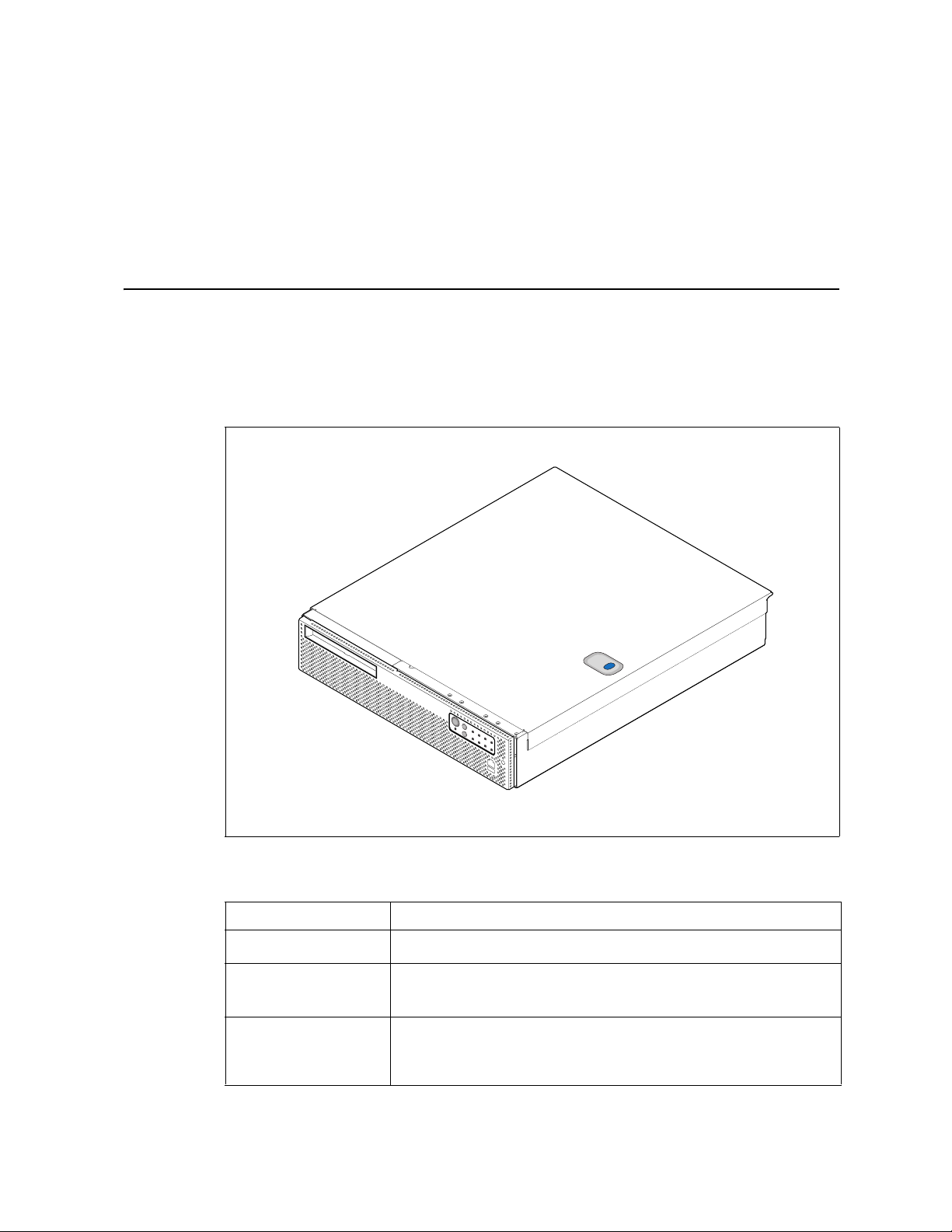
This chapter briefly describes the main features of the Kontron Carrier Grade Server TIGH2U. This
chapter provides a diagram of the product, a list of the server features, and diagrams that show the
location of important components and connections.
Figure 1 shows the Kontron Carrier Grade Server TIGH2U.
Figure 1. K
ontron Carrier Grade Server TIGH2U
Tab le 1 summarizes the major features of the server system.
Table 1. K
December 2009 Product Guide, rev.1.2
ontron Carrier Grade Server TIGH2U Features
Feature Description
Compact, high-density
syst
em
Configuration flexibility One- or two-way capability in low-profile and cost / v
Serviceability Rear access to hot-swappable power supplies
Rack-mount server with a height of 2U (3.45 inches, 8.9 cm) and a depth of
20.0 inches (50.8 cm)
Stand-alone system
Supports up to two Quad-Core Intel
Front access to hot-swappable SAS disk drives
Front access to optical drive
Ability to swap the entire drive bay as a unit
11
®
Xeon® processor 5400 series †
Kontron Carrier Grade Server TIGH2U
alue-effective packaging
Page 12
Table 1. Kontron Carrier Grade Server TIGH2U Features (Continued)
Feature Description
Availability Two hot-swappable 600 W power supplies in a redundant (1+1) configuration
Disk subsystem configurable as hardware or software RAID
Memory sparing and memory mirroring configurations supported
Manageability Remote management
Emergency management port (serial and LAN)
IPMI 2.0 compliant
Remote diagnostics support
Optional SMART Embedded USB Solid-State Drive
Optional Intel® Remote Management Module 2 (Intel® RMM2) providing GCM
support
Upgradeability and
investment protection
System-level scalability Supports up to 32 Gbytes FBDIMM memory in non-mirrored mode
Front panel Switches:
I/O Front panel:
Internal connection options Internal connectors/headers:
Add-in card support One full-height riser slot supporting 2U PCI-X and PCIe add-in cards
† For a list of compatible processors, see http://us.kontron.com/support/.
Supports up to two Quad-Core Intel® Xeon® processor 5400 series †
Multi-generational chassis
Intel® 64 architecture support
Supports up to 16 Gbytes FBDIMM memory in mirrored mode
Supports up to two Quad-Core Intel® Xeon® processor 5400 series †
Two full-height / full-length x4 PCI Express* (PCIe)* slots
One full-height / full-length 64-bit x 133 MHz PCI-X* slot
Two low-profile / half-length x4 PCI Express slots
Six internal hot-swappable 2.5-nch SAS disk drives
One optical drive (optional)
•Power switch
• Reset switch
• NMI switch
•ID switch
• Serial B port (RJ45)
•USB 2.0 port
• One 44-pin ATA/100 connector (power and I/O) for optical drive
•One Intel® Remote Management Module 2 (Intel® RMM2) connector
•One Intel® I/O Expansion Module (optional) supporting either:
- a dual GbE NIC Intel® connection
- an external x4 SAS drive
One low-profile riser slot supporting PCIe add-in cards
LEDs / Relays:
• Telco critical alarm fault LED / relay
• Telco major alarm fault LED / relay
• Telco minor alarm fault LED / relay
• Telco power alarm fault LED / relay
•ID LED
•NIC activity LED
•Main power LED
•HDD activity LED
Rear panel:
• Dual PS/2 ports for keyboard and mouse
• Serial B port (RJ45)
• Two USB 2.0 ports
•Intel® RMM2 NIC 100 Mbps management
port
• Two RJ45 NIC connectors for 10 / 100 /
1000 Mbps connections
• Video connector
• Alarms connector
TIGH2U Server—Features
Kontron Carrier Grade Server TIGH2U
Product Guide, rev.1.2 December 2009
12
Page 13
TS000343
F
A
B
J
K
C
D
E
G
H
L
I
Note: View with fan ducting removed.
Features—TIGH2U Server
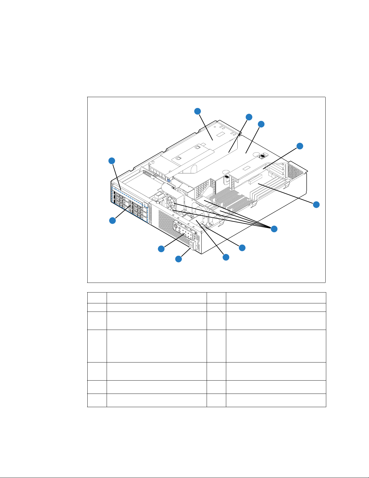
2.1 Server Components
Figure 2 shows the TIGH2U Server with top cover and front bezel removed to show the internal
components. The components are listed on the next page.
Figure 2. Carrier Grade Server TIGH2U Components
December 2009 Product Guide, rev.1.2
Item Description Item Description
A Optical drive (optional) G System fans
Power supply cage (contains one power
B
s
upply module with provision for an optional
second module)
Provision for PCI-X* and
C
(PCIe*) full-height and full-length add-in
cards
Riser card assembly (containing riser cards
D
fo
r both full-height and low-profile add-in
cards)
Provision for two PCI Express low-profile
E
ad
d-in cards
®
F Intel
Server Board T5000PAL L
PCI Express*
H SAS front panel (SFP) board
TAM board (behind front panel)
Note: Th
I
J RJ45 COM2 and USB port 2 connectors
K Control panel and status indicators
Hot-swappable SAS 2.5-inch disk drives (up
to
six)
Kontron Carrier Grade Server TIGH2U
13
e bracket on which the TAM board
is installed can also include an
optional SMART Embedded USB
Solid-State Drive, which provides
local memory storage
Page 14
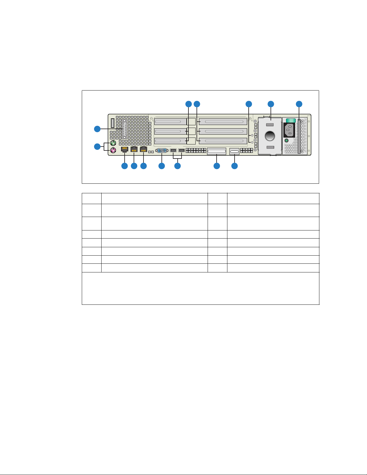
2.2 Back Panel
TS000354
01
L
K
G F
J
I
H
A
D
E
B
C
N
M
Figure 3 shows the back panel of the TIGH2U Server.
Figure 3. Rear View
Item Description Item Description
Low-profile PCI Express add-in cards
A
(or filler panels)
Full-height PCI-X/PCI Express add-in cards (or
B
filler pane
C Ground studs (used for DC-input system) J GbE NIC #2 connector ††††
D Power supply 2 slot; filler panel shown K GbE NIC #1 connector ††††
E Power supply 1 † L RJ45 serial port connector
F RMM2 NIC connector (optional) †† M PS/2 keyboard and mouse connectors
G I/O expansion module connector (optional) ††† N Alarms connector
†In Figure 3, the power supply shown is an AC-input modul
†† If an RMM2 NIC is not present, a fi
††† May be either an external SAS port connector or Gigabit Etherport port connector. If neither of the
optional m
†††† The GbE ports are only designed to pass intra-building lightn
cabling, which must be grounded at both ends.
ls)
ller panel occupies this space.
odules is installed, a filler panel occupies this space.
TIGH2U Server—Features
H USB 0 and USB 1 port connectors
I Video connector
e. DC-input modules are also available.
ing surge when used with shielded
Kontron Carrier Grade Server TIGH2U
Product Guide, rev.1.2 December 2009
14
Page 15
TS000345
Alarms
Status
ID ONNIC
CRT MNR PWRMJR
A
C B
Features—TIGH2U Server
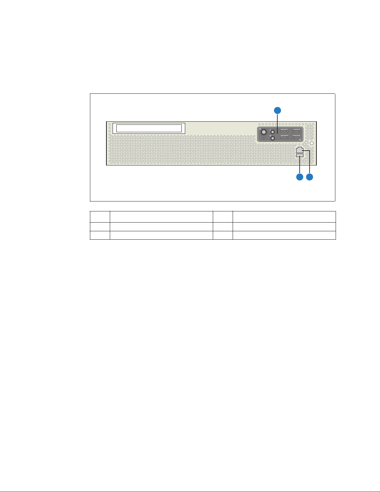
2.3 Front Panel
Figure 4 shows the front panel of the TIGH2U Server with the bezel installed.
Figure 4. Front View (Bezel Installed)
Item Description Item Description
A Front panel control switches and status LEDs C USB port
B COM port
December 2009 Product Guide, rev.1.2
15
Kontron Carrier Grade Server TIGH2U
Page 16
TIGH2U Server—Features
Alarms
Status
ID ONNIC
CRT MNR PWRMJR
TS000346
A B C
DEK HJ GI F
L
M
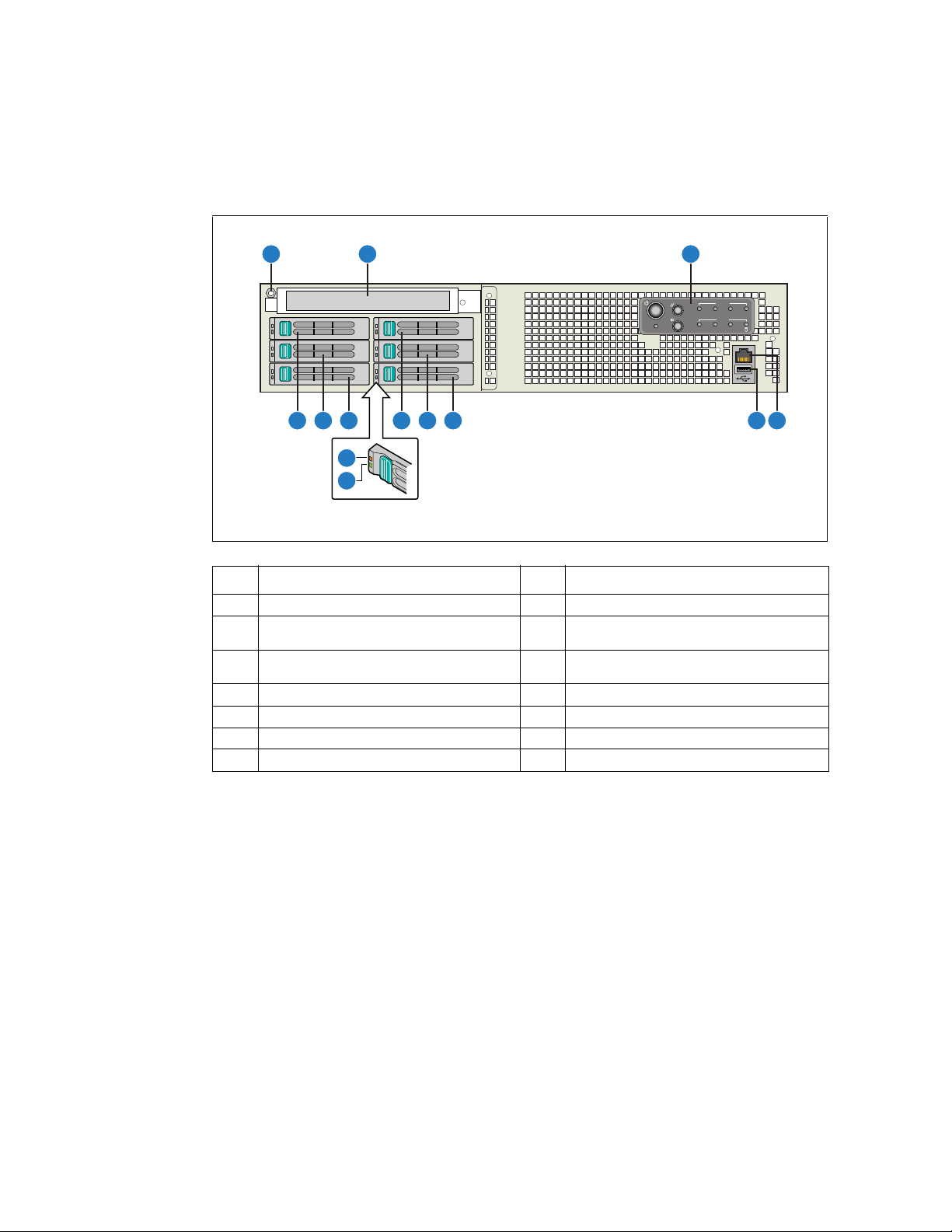
Figure 5 shows the front panel of the TIGH2U Server with the bezel removed. The components are
listed on the next page.
Figure 5. Front View (Bezel Removed)
Item Description Item Description
A Anti-static connection point H Hard drive bay 4
Optical drive (optional) or filler panel if no
B
driv
e is installed
Front panel control switches and status LEDs
C
(See Figure 6 for details)
D Front panel serial port connector (RJ45) K Hard drive bay 5
E USB port 2 connector L Drive fault indicator (one per hard drive)
F Hard drive bay 0 M Drive activity indicator (one per hard drive
G Hard drive bay 2
I Hard drive bay 1
J Hard drive bay 3
Kontron Carrier Grade Server TIGH2U
Product Guide, rev.1.2 December 2009
16
Page 17
Alarms
Status
ID ONNIC
CRT MNR PWRMJR
A B E F G H
C D I J K L
TS000347
Features—TIGH2U Server
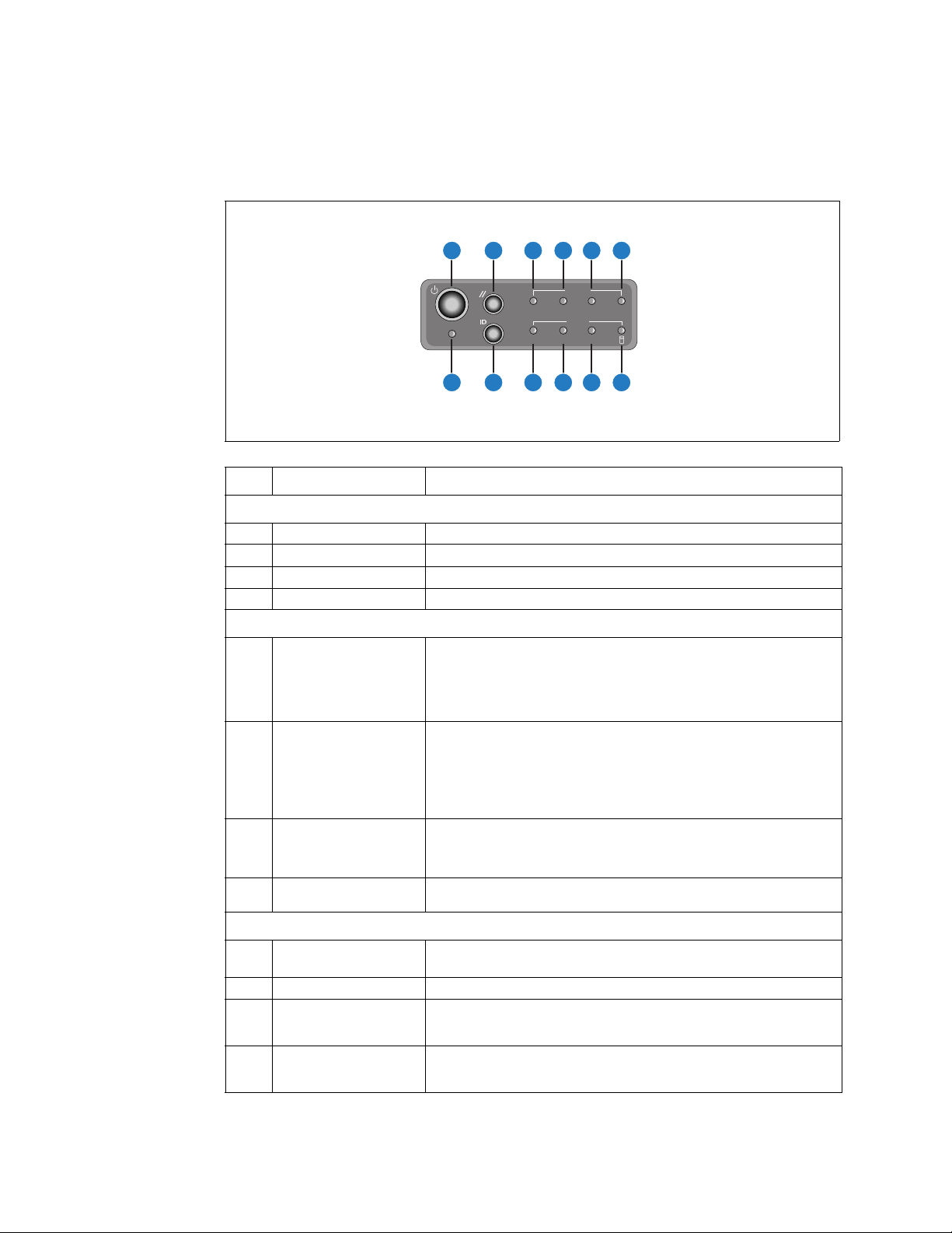
Figure 6 shows the control panel.
Figure 6. Control Panel
December 2009 Product Guide, rev.1.2
Item Feature Description
Front Panel Switches
A Power switch Toggles the system power
B Reset switch Resets the system
C NMI switch (pin hole) Asserts NMI to the server board
D ID switch Toggles the system ID LED on / off
Front Panel Alarm LEDs and Relays
The Critical alarm LED can be either amber (default) or red (set with an
FRUSD
R update). When continuously lit, indicates a Critical System Fault
E Critical (amber or red)
F Major (amber or red)
occurred. A critical system fault is an error or event that has a fatal
system impact. In this case, the system cannot continue to operate. An
example is the loss of a large section of memory, or other corruption. The
front panel critical alarm relay is engaged.
The Major alarm LED can be either amber (default) or red (set with an
R update). When continuously lit, indicates a Major System Fault
FRUSD
occurred. A major system fault is an error or event that has discernible
impact to the system operation. In this case, the system can continue to
operate, but in a degraded fashion (reduce performance or with the loss
of non-fatal features). An example is the loss of a mirrored disk. The front
panel major alarm relay is engaged.
When continuously lit, indicates a Minor System Fault occurred. A minor
ystem fault typically has little impact to the system operation. An
G Minor (amber)
H Power (amber)
s
example is a correctable ECC error. The front panel minor alarm relay is
engaged.
When continuously lit, indicates a Power System Fault occurred. The front
panel power alarm rela
y is engaged.
Front Panel Status LEDs
I System ID LED (white)
Indicates system identity
This LED can be toggled remotely or by front panel ID switch
J NIC activity LED (green) Indicates NIC activity when lit
When continuously lit, indicates the pres
K Main power LED (green)
HDD activity / fault LED
L
een / amber)
(gr
power in the server. The LED turns off when the main output power from
the power supply is turned off or if the power source is disrupted.
Indicates HDD activity when green or an HDD fault when amber. This is an
agg
regated indication for all hard drives in the system (up to six). Each
hard disk contains its own activity and fault indicators.
17
ence of power supply DC output
Kontron Carrier Grade Server TIGH2U
Page 18

TIGH2U Server—Features
2.4 Rear Panel Ethernet Ports
The TIGH2U Server has two GbE NIC ports that are mounted on the server board and accessible from
the rear of the chassis. Additional rear-accessible GbE NIC ports can be added by using full-height
PCI-X/PCIe add-in cards or low-profile PCIe add-in cards.
A dual GbE I/O option module is available. This module adds two RJ45, 1 Gigabit Ethernet ports
accessible on the rear panel. The GbE NIC ports are intended to be installed with shielded cabling that
is grounded at both ends of the cable.
The possible configurations of full-height PCI-X/PCIe add-in cards are in Tabl e 2 on page 21 and the
possible configurations of low-profile PCIe add-in cards are in Tab le 3 on page 21.
Warning: The intra-building port(s) of the equipment or subassembly is suitable for connection to
intra-building or unexposed wiring or cabling only. The intra-building port(s) of the
equipment or subassembly MUST NOT be metallically connected to interfaces that
connect to the OSP or its wiring. These interfaces are designed for use as intra-building
interfaces only (Type 2 or Type 4 ports as described in GR-1089-CORE, Issue 4) and
require isolation from the exposed OSP cabling. The addition of Primary Protectors is
not sufficient protection to connect these interfaces metallically to OSP wiring.
2.5 SAS Front Panel (SFP) Board
The SAS Front Panel (SFP) board adds SAS support and provides support for hardware RAID 0, 1, 10,
and 5, and software RAID 0, 1, and 10. This board is located on the floor of the chassis between the
front panel and the two 80 mm fans.
2.5.1 SFP Board Features
The TIGH2U Server SFP board has the following features:
• One RS-232 front panel port
• One USB2.0 front panel port
• One USB2.0 interface to local memory storage
• One flex cable connection to the SAS backplane to support the interface to six independent 2.5inch SAS hard drives
• One socket for a DDR2 mini-DIMM that provides data caching for hardware RAID
• One connector for the Intel® RAID Smart Battery that allows the contents of the DDR2 mini-DIMM
to be preserved if power falls below specifications.
• Four fan connectors to provide power, control, and monitoring for the four cooling fans
• Four fan fault LEDs (for diagnostics purposes only, not visible on front panel)
2.6 Telco Alarms Manager Board
The Telco Alarms Manager (TAM) board adds LEDs and power functions to the front of the server
chassis. It also uses a cable to provide an alarms function with fault relays to the back of the chassis.
This board is located over the top of the SFP board between the front panel and the two 80 mm fans.
Kontron Carrier Grade Server TIGH2U
Product Guide, rev.1.2 December 2009
18
Page 19
TS000277
K
L
J
Q P O NR M
BB
CC
AA
Z
Y
X
W
T
U
S
BA ED F HGC
I
V
Features—TIGH2U Server
2.6.1 TAM Board Features
The TIGH2U Server TAM board has the following features:
• Four switches to control power on, reset,
• One system ID LED that can be controlled remotely
NMI, and the system ID LED
or by the system ID switch
• Two system activity LEDs that indicate power-on and NIC activity
• One hard drive / fault LED that indicates activity or faults for any of the six HDDs
• Four system fault LEDs that indicate critical, major, minor, and power system fault status
• Four system fault relays for external critical, major, minor, and power fault indicators
• One connector to interface with the SFP board
• One connector to route the contacts of the four system fault relays to a connector at the back of
the chassis
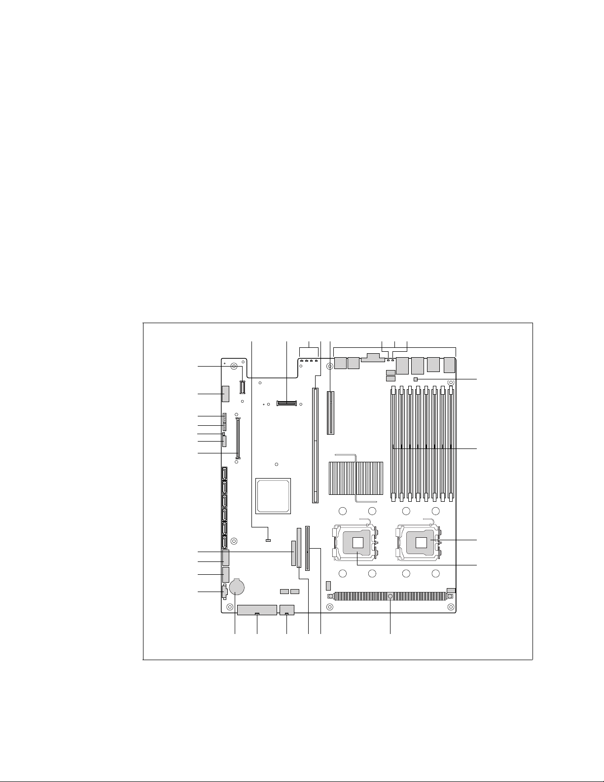
2.7 Server Board Connector and Component Locations
Figure 7 shows the locations of connectors and components on the T5000PAL Server Board.
Figure 7. Intel® Server Board T5000PAL Layout
December 2009 Product Guide, rev.1.2
19
Kontron Carrier Grade Server TIGH2U
Page 20
TIGH2U Server—Features
Description Description
A BIOS Bank Select Jumper P CPU Power Connector
B I/O Module Option Connector Q Main Power Connector
C POST Code Diagnostic LEDs R Battery
®
D Intel
E PCI Express Riser Slot – Low-profile T Dual Port USB 2.0 Header
F System Identification LED - Blue U Serial Port Connector
G External I/O Connectors V SSI 24-pin Control Panel Header
H Status LED – Green/Amber W
I Serial ‘B’ Port Configuration Jumper X System Recovery Jumper Block
J FBDIMM Sockets Y Chassis Intrusion Switch Header
K CPU #1 Connector Z 3-pin IPMB Header
L CPU #2 Connector AA Intel
M Voltage Regulator Heat Sink BB Serial ‘A’ Header
N Bridge Board Connector CC Intel
O
Note: In Figure 7, connectors shown but not called out are “not used”.
Adaptive Slot – Full-height S Power Supply Management Connector
®
Intel
Remote Management Module 2 (Intel®
RMM) Connector
®
Local Control Panel Header
®
RMM2 NIC Connector
ATA-100 Optical Drive Connector
(power and I/O)
2.8 Hard Disk Drives
The TIGH2U Server chassis supports up to six 2.5-inch SAS drives in hot-swappable hard drive tray
assemblies at the front of the chassis.
For information on how to install these drives, see Section 3.3.1, “Installing or Replacing a Hard
Drive”.
Note: The
Drives can consume up to 17 W of power each. Drives must be specified to run at a maximum
ambient temper
TIGH2U Server does not support all SAS hard drives. For a list of validated hard
drive manufacturers and hard drive types, see the Tested Hardware and Operating
Systems List (THOL) at
http://us.kontron.com/support/
ature of 45° C.
ntron Carrier Grade Server TIGH2U
Ko
Product Guide, rev.1.2 December 2009
20
Page 21
Features—TIGH2U Server
2.9 Riser Card Assembly
The Carrier Grade Server TIGH2U incorporates a PCI riser assembly that supports installation of PCIX and PCI Express add-in boards. The assembly includes two riser cards that connect into the Intel
®
Server Board S5000PAL.
• One of the riser card slots facilitates installing PCI-X* and PCI Express* add-in cards.
• The second riser card slot facilitates installing low-profile PCIe add-in cards.
See Section 4.2, “Installing or Replacing a PCI Add-in Card” on page 53, for instructions describing
how to install a PCI-X or PCIe add-in card. After the
add-in cards are installed, the riser assembly is
plugged back into the system and the I/O brackets of all the add-in cards are accessible through the
rear panel of the server chassis.
2.9.1 Full-Height PCI-X/PCIe Riser Card
The PCI-X/PCIe riser card plugs into the super slot on the server board. For PCI-X add-in cards, the
super slot riser card implements a 64-bit PCI-X slot with bus speeds of 66 MHz, 100 MHz, or 133 MHz.
F
or PCIe cards, the super slot has eight PCIe lanes which can be used for a single x8 add-in card or
for one or two x4 or x1 add-in cards. See Tabl e 2 for the supported configurations. For detailed
information about the pinouts and electrical specifications, see the K
TIGH2U Technical Product Specification.
Table 2. Full-Height Riser Card Configurations and Throughput
Configuration Bottom Slot Middle Slot Top Slot
PCI-X † – –
One add-in card
Two a d d - in cards
Three add-in cards PCI-X † x4 PCIe x4 PCIe
Note: † U
p to 133 MHz bus speed
– x8 or x4 PCIe –
– – x4 PCIe
PCI-X † x8 or x4 PCIe –
PCI-X † – x4 PCIe
– x4 PCIe x4 PCIe
ontron Carrier Grade Server
2.9.2 Low-Profile PCIe Riser Card
The low-profile PCIe riser card plugs into the server board and supports the connection of low-profile
PCIe add-in cards only. The low-profile PCIe riser card implements two ×4 link interfaces. Up to two
low-profile PCIe add-in cards can be installed. See Tabl e 3 for the supported configurations. For
detailed information about the pinouts and electrical specifications, see the Ko
Server TIGH2U Technical Product Specification.
Table 3. Low-Profile PCI Add-in Card Configuration
Configuration Lower Slot Upper Slot
One add-in card
Two a d d - in cards x4 PCIe x4 PCIe
December 2009 Product Guide, rev.1.2
x4 PCIe
21
s and Throughput
x4 PCIe
ntron Carrier Grade
Kontron Carrier Grade Server TIGH2U
Page 22
TIGH2U Server—Features
A
B
TS000419
2.10 Power Supply
The power subsystem has a power distribution board (PDB) and up to two hot-swap power supply
modules capable of operating in redundant mode. A power supply filler panel for the empty power
supply site is supplied for systems without redundancy.
The power supply is rated for 600 W output capability in full AC (or
DC) input voltage range.
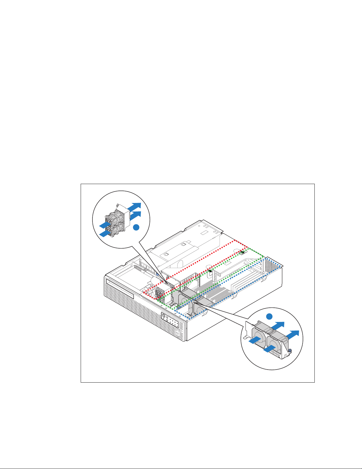
2.11 System Cooling
There are three cooling areas (domains) in the TIGH2U Server system:
• Domain 1 - CPU 1 and memory; see area outlined in blue in Figure 8
• Domain 2 - CPU 2, chipset, and any low-profile PCIe add-in cards; see
Figure 8
• Domain 3 - any full length PCI-X or PCIe add-in cards; see area outlined in red in Figure 8
Letter A in the following figure calls out the
PCI fans. Letter B calls out the CPU fans.
Figure 8. System Cooling Areas
area outlined in green in
Kontron Carrier Grade Server TIGH2U
Product Guide, rev.1.2 December 2009
22
Page 23
Features—TIGH2U Server
2.11.1 CPU 1 and Memory Cooling Area
One of the system’s large fans provides cooling for domain 1, outlined in blue in Figure 8. This fan
facilitates the flow of air through the front bezel over the SF
P, through the fan, and over the server
board, CPU 1, memory, and ultimately out through the rear of the chassis.
2.11.2 CPU 2 and Chipset Cooling Area
One of the system’s large fans provides cooling for domain 2, outlined in green in Figure 8. This fan
facilitates the flow of air through the front bezel over the SF
P, through the fan, and over the server
board, CPU 2, chipset and any low-profile PCIe add-in cards, and ultimately out through the rear of
the chassis.
2.11.3 PCI Cooling Area
The two 40 × 40 × 56 mm dual-rotor fans (A in Figure 8) facilitate the flow of air through the front
bezel, through the fans, over the server board and any full-length PCI-X or PCIe add-in cards, and
ultimately ou
t through the rear of the chassis.
2.11.4 Hard Disk Drive and Power Supply Cooling
Fans that are integrated into the PSUs provide the airflow to cool the hard disk drives. The airflow is
adequate even with a single PSU installed as long as a filler panel is installed in the other PSU slot.
2.11.5 Fan Speed Control
The server board contains Pulse Width Modulation (PWM) circuits, which control the 12 VDC fan
voltage to provide quiet operation when system ambient temperature is low and there are no fan
failures. There is one PWM circuit for each cooling domain, resulting in one PWM being connected to
each of the two 80 × 38 mm fans and the other PWM connected to the two dual-rotor 56 × 40 mm
fans. Based on the ambient temperature, monitored by the front panel sensor, the fan speeds (PWM
duty cycle) are set per Tab le 4.
Table 4. Fan Speed Settings
Temperature (°C)
0 - 28 46 46 46
29 47 47 47
30 48 48 48
31 53 53 53
32 58 58 58
33 63 63 63
34 68 68 68
35 73 73 73
36 78 78 78
37 84 84 84
38 89 89 89
39 95 95 95
40 100 100 100
CPU1 Fan
PWM DC (%)
CPU2 Fan
PWM DC (%)
PCI Fans
PWM DC (%)
December 2009 Product Guide, rev.1.2
23
Kontron Carrier Grade Server TIGH2U
Page 24

TIGH2U Server—Features
2.11.6 Cooling Summary
The four-fan cooling subsystem of the TIGH2U Server is sized to provide cooling for:
• Up to two server board processors
• Up to 32 Gbytes of FBDIMM memory
• Up to six SAS hard drives
• Up to five PCI add-in cards consuming a maximum of 25 W for each full-height
PCI-X / PCIe add-in cards and 10 W for each low-profile PCIe add-in card
The cooling subsystem meets acoustic and thermal requirements at the lower fan speed settings. At
the higher fan speed settings, thermal requirements are met for the maximum ambient
temperatures, but acoustic requirements are not met.
2.12 Hardware Requirements
To avoid integration difficulties and possible board damage, your system must meet the requirements
outlined below. For a list of qualified components, see
Software”.
2.12.1 Processor
Section 1.4, “Additional Information and
The server board accommodates two Quad-Core Intel® Xeon® processor 5400 series. For a list of the
currently supported processors, see the product support page at:
http://us.kontron.com/support/
2.12.2 Memory
The memory controller hub (MCH) on the T5000PAL server board accommodates four channels of
fully buffered DIMM (FBDIMM) memory. Each channel can support up to two dual-ranked FBDIMM
DDR2 DIMMs. FBDIMM memory channels are organized into two branches for support of RAID 1
(mirroring). See
population rules and instructions for installing DIMMs in the sockets on the server board.
Section 3.4.2, “Configuring Memory DIMMs” for detailed information about
Kontron Carrier Grade Server TIGH2U
Product Guide, rev.1.2 December 2009
24
Page 25

Server Component Installations and Upgrades—TIGH2U Server
3 Server Component Installations and Upgrades
3.1 Before You Begin
Before working with your server product, pay close attention to the safety instructions provided in this
manual. See
Warning: Electrostatic discharge (ESD) and ESD protection: ESD can damage disk drives,
3.1.1 Tools and Supplies Needed
Appendix A, “Safety Information”.
boards, and other parts. Perform the procedures in this chapter at an ESD workstation.
If one is not available, provide some ESD protection by wearing an antistatic wrist strap
attached to chassis ground (any unpainted metal surface) on your server when
handling parts.
• #1 and #2 Phillips (cross-point) screwdrivers (or interchangeable tip screwdriver with #1 and #2
Phillips bits)
• Personal grounding device such as an anti-static wrist strap and a grounded conductive pad
3.1.2 System References
All references to left, right, front, top, and bottom assume that you are facing the front of the server,
as it would be positioned for normal operation.
3.2 General Installation Procedures
The following sections present general installation and removal procedures that are required before
removing or installing internal components that are not hot-swappable.
3.2.1 Removing the Front Bezel
Remove the front bezel to
• Install or remove hard drives or an optical device
• Access the front-panel serial port and USB connectors
• Observe the individual HDD activity/fault indicators
• Install or remove the optional Intel® RAID Smart Battery
December 2009 Product Guide, rev.1.2
Kontron Carrier Grade Server TIGH2U
25
Page 26
TIGH2U Server—Server Component Installations and Upgrades
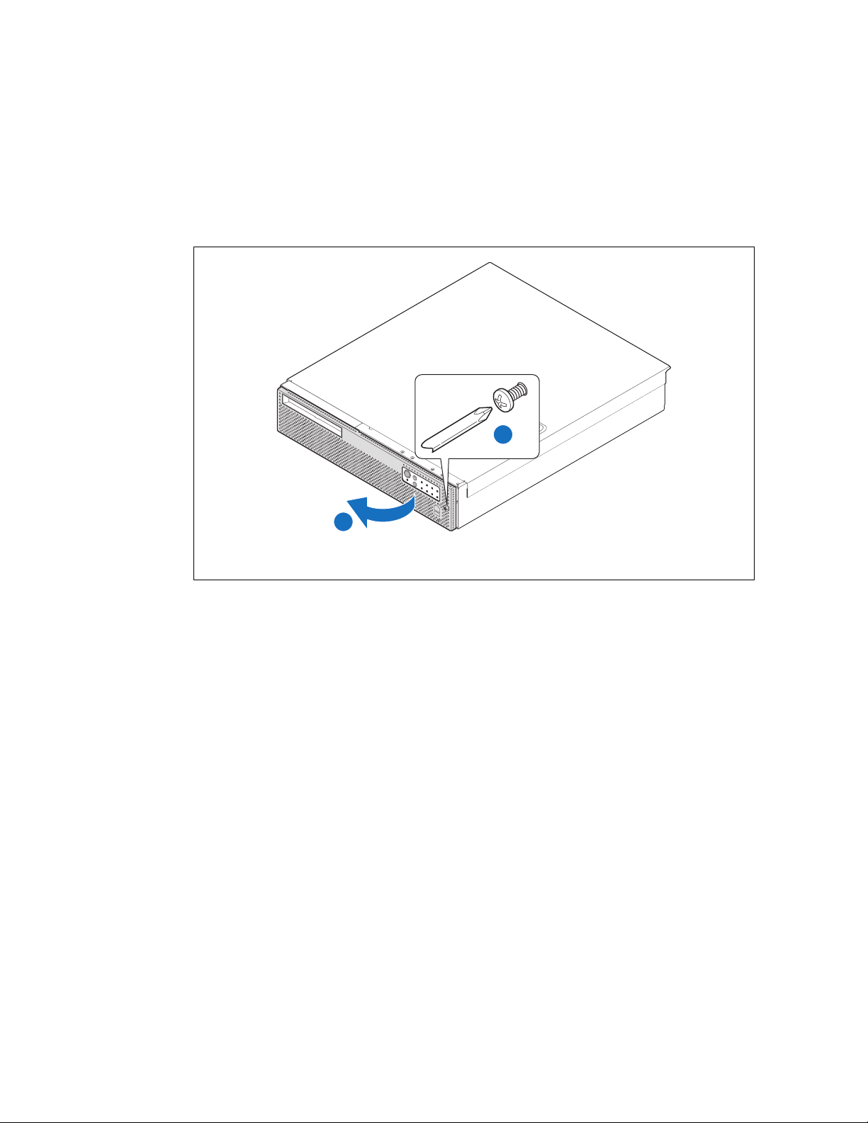
Note: The front bezel can be removed while the server power is on.
1. Disconnect the cables from the front panel USB port and / or serial port connectors.
2. Loosen the bezel retention screw from the right side. (“A”)
3. Rotate the bezel outward as shown and remove. (“B”)
Figure 9. Removing the Front Bezel
A
B
TS000423
3.2.2 Installing the Front Bezel
1. Align the four tabs on the left side of the bezel with the slots in the front panel and then rotate the
free end of the bezel to the closed position.
2. Snap the front bezel into place and tighten the screw at the right edge of the bezel (if used).
3. Re-connect the serial port and USB cables if they are used.
3.2.3 Removing the Chassis Cover
The TIGH2U Server must be operated with the top cover in place to ensure proper cooling. You will
need to remove the top cover to add or replace components inside of the server that are not hotswappable from the front or rear panels.
Caution: 5
Before removing the top cover, power down the server system
the power cable.
Note: A
1. Observe the safety and ESD precautions in Appendix A, “Safety Information”.
2. Turn off all peripheral devices connected
3. Disconnect the power cord(s).
V standby power is present inside the chassis whenever the PSU(s) are connected to
a source of power.
and unplug all peripheral devices and
non-skid surface or a stop behind the server may be needed to prevent the server
from sliding on your work surface.
to the server. Turn off the server.
Kontron Carrier Grade Server TIGH2U
Product Guide, rev.1.2 December 2009
26
Page 27
B
A
TS000422
Server Component Installations and Upgrades—TIGH2U Server
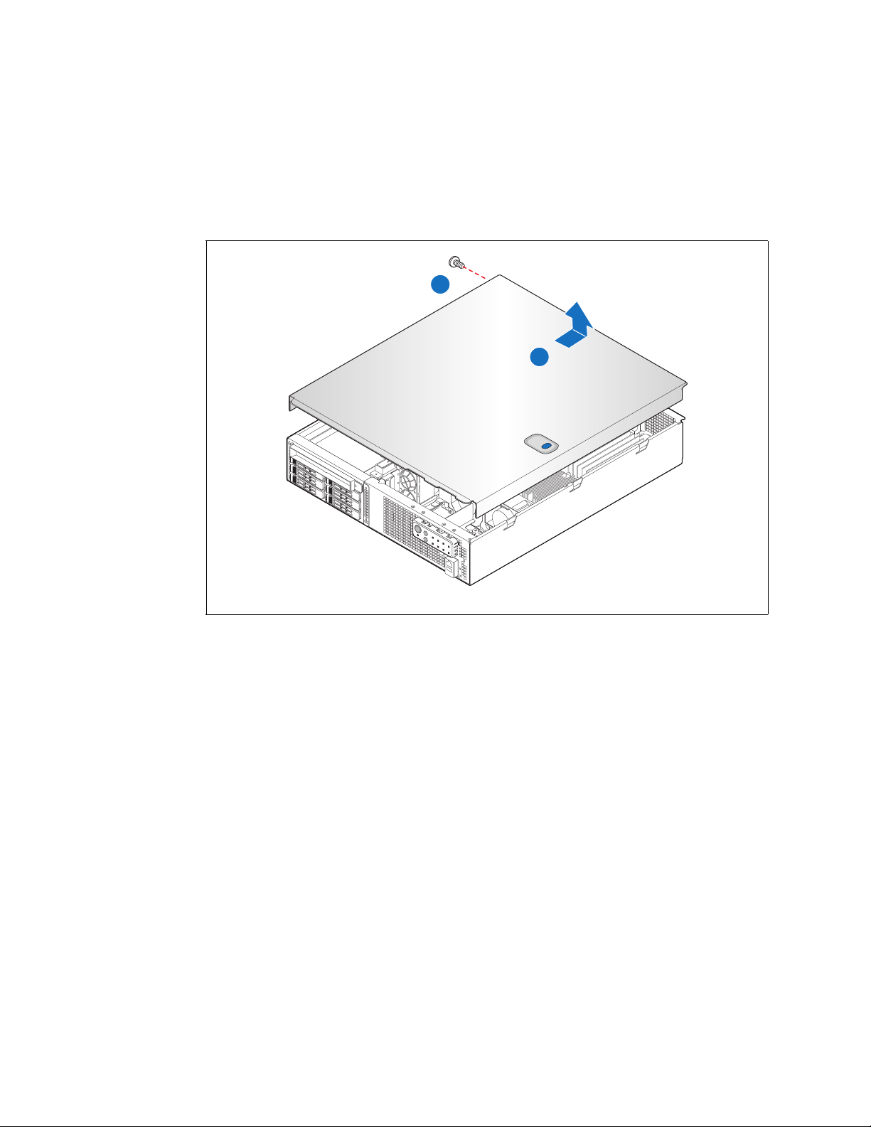
4. Remove the shipping screw at the left side, near the rear.
5. While holding the blue button at the top of the chassis in
stops.
6. Lift the cover straight up to remove it from the server.
Figure 10. Removing the Chassis Cover
(“A”), slide the top cover back until it
3.2.4 Installing the Chassis Cover
1. Place the cover over the chassis so that the side edges of the cover sit just inside the chassis side
walls, with the front of the cover with about 1/8-inch (3-mm) gap showing between the chassis
cover and the sheet-metal at the front of the chassis.
2. Press down slightly on the chassis cover behind the
peripheral area and slide the cover forward
until it clicks into place.
3. Install the shipping screw if tooled entry is required or if the system will be shipped.
4. Reconnect all peripheral devices and the power cord(s).
Caution: This unit must be operated with the top cover installed to ensure proper cooling.
December 2009 Product Guide, rev.1.2
Kontron Carrier Grade Server TIGH2U
27
Page 28
TIGH2U Server—Server Component Installations and Upgrades
TS000273
A
B
C
E
D
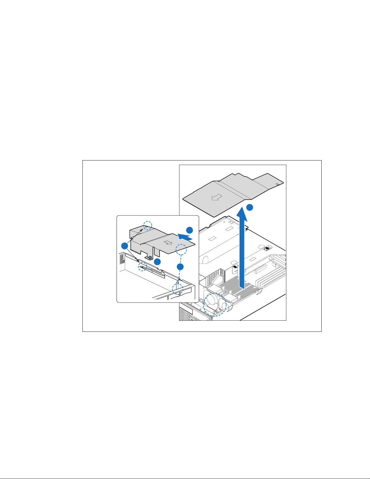
3.2.5 Removing the Processor Air Duct
The air duct must be removed to access the processors, memory DIMMs, CPU fan assembly, the SFP
board, or the inside of the front panel. The processor air duct is required for proper airflow within the
chassis. Be sure the air duct is in place before installing the chassis cover.
1. Power down the server system and unplug all pe
2. Remove the chassis cover. For instructions, see Section 3.2.3, “Removing the Chassis Cover”.
3. Loosen the captive fastener on the left side of the air duct. (“A”)
4. Slide the duct several millimeters toward t
The front edge will disengage from the front panel. (“C”)
The metal tab at the rear will release. (“D”)
5. Lift the air duct straight up and remove it from the chassis. (“E”)
Figure 11. Removing the Processor Air Duct
ripheral devices and the AC power cable.
he rear panel until it stops. (“B”)
Kontron Carrier Grade Server TIGH2U
Product Guide, rev.1.2 December 2009
28
Page 29
TS000467
E
C
B
A
D
Server Component Installations and Upgrades—TIGH2U Server
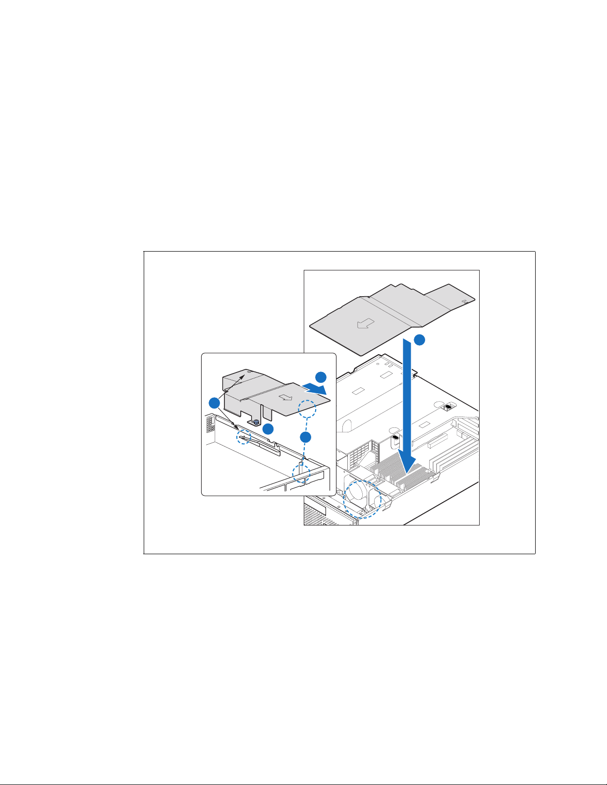
3.2.6 Installing the Processor Air Duct
1. Place the processor air duct over the processor sockets and fan assembly, using caution to make
sure you do not pinch any cables beneath the edges of the air duct. (“A”)
The top of the installed air duct should be flush with the top surface
assembly.
The front of the air duct should line up with the metal tab. (“B”)
2. Slide the air duct forward until it is flush with the front panel. (“C”)
3. Ensure that the rear of the air duct is fastened to the metal tab on the chassis. (“D”)
4. Tighten the captive fastener. (“E”)
5. Replace the chassis cover if you have completed all work inside of the chassis.
Figure 12. Installing the Processor Air Duct
of the PCI riser card
December 2009 Product Guide, rev.1.2
Kontron Carrier Grade Server TIGH2U
29
Page 30
TIGH2U Server—Server Component Installations and Upgrades
TS000274
54
32
10
A
3.3 Hot-Swappable Component Installation Procedures
The following components are hot-swappable and do not require powering down the system or
removing the chassis cover:
• Hard disk drives
• AC and DC power supplies (if power redundancy is a
3.3.1 Installing or Replacing a Hard Drive
Up to six hot-swappable SAS drives can be installed in your TIGH2U Server. You must remove the
front bezel to add or replace a hard drive in one of the six drive bays.
vailable)
Caution: If y
The Carrier Grade Server TIGH2U does not support all SAS hard drives. To see a list of validated
manufacturers and hard drive types, see the Tested Hardware and Operating System List (THOL) at :
http://us.kontron.com/support/
Click on Downloads and then Compatability Matrix.
ou install fewer than six hard drives, the empty bays must have drive trays with
baffles in them to maintain proper system cooling.
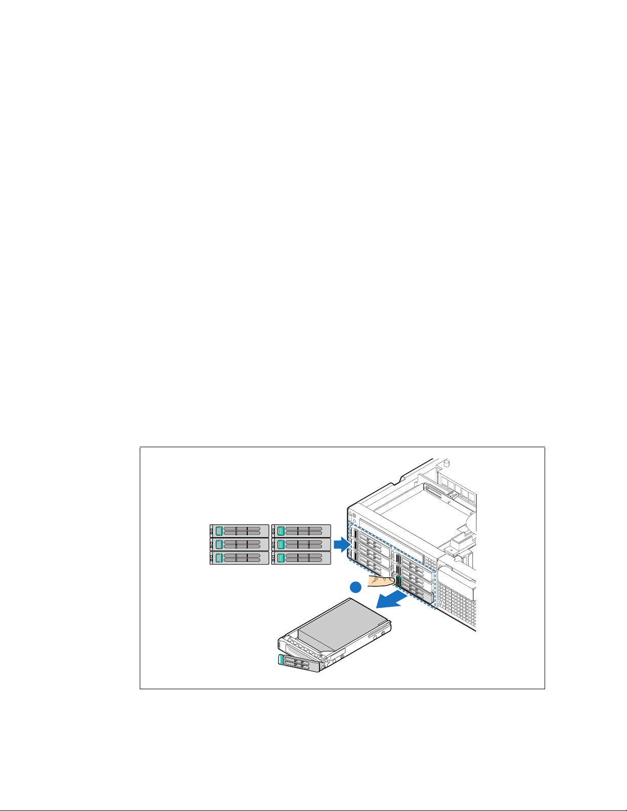
3.3.1.1 Removing a Hard Drive Tray
1. Remove the front bezel. For instructions, see Section 3.2.1, “Removing the Front Bezel”.
2. Select the drive bay where you want to install the d
green button to open the lever. (“A”)
Note: If y
3. Pull the drive tray assembly out of the chassis.
Figure 13. Removing a Drive Tray
ou will have fewer than six drives installed, drive bay 0 must be used first, then
drive bay 1, and so forth.
rive and remove the drive tray by pressing the
Kontron Carrier Grade Server TIGH2U
Product Guide, rev.1.2 December 2009
30
Page 31

AF000810
A
B
Server Component Installations and Upgrades—TIGH2U Server
3.3.1.2 Attaching a Hard Drive to the Drive Tray
1. If a drive is already installed (that is, if you are replacing the drive), remove it by unfastening the
four screws that attach it to the drive tray. (“A”)
Figure 14. Removing a Hard D
rive from the Drive Tray
A
TS000219
2. Install the new drive in the drive tray and secure the drive with the four screws provided with the
drive tray. (Figure 15, “A” and “B”)
Figure 15. Installing a Hard Drive in the Drive Tray
December 2009 Product Guide, rev.1.2
Kontron Carrier Grade Server TIGH2U
31
Page 32

TIGH2U Server—Server Component Installations and Upgrades
A
TS000275
3. With the drive tray locking lever fully open, push the hard drive tray into the drive bay in the
chassis until it stops. (Figure 16, “A”)
4. Press the lever until it snaps shut to secure the drive in the bay.
5. Replace the front bezel.
Figure 16. Inserting a New SAS Drive Assembly
3.3.2 Replacing a Power Supply
Caution: Your server does not have a redundant power supply unless you have purchased the
optional second power supply. If there is no second supply, before replacing the power
supply you must first take the server out of service, turn off all peripheral devices
connected to the system, turn off the system by pressing the power button, and unplug
the power cord(s) from the system or wall outlet.
To maintain hot-swap capability, make sure that
in both chassis slots before replacing (hot-swapping) a power supply module.
The TIGH2U Server supports th
Kontron Carrier Grade Server TIGH2U
Product Guide, rev.1.2 December 2009
32
e use of either AC (Figure 17, “C”) or DC (“D”) power supply modules.
there is an active power supply module
Page 33

Server Component Installations and Upgrades—TIGH2U Server
3.3.2.1 Removing the Power Supply Module
1. Check the status LED to determine which power supply has failed and disconnect the appropriate
power cable. (Figure 17, “A”)
2. Press and hold the green safety lock downw
3. Grasp the handle (“B”) and pull the power supply module from the chassis.
Figure 17. AC and DC Power Supplies
ard to disengage the power supply module.
AC PS DC PS
A
C
B
3.3.2.2 Installing a Power Supply Module
1. Slide the power supply module into the chassis slot until it clicks into place.
2. Make sure the power supply is fully inserted by pulling on
the power supply will not slide out without pressing the green safety lock.
the handle. When correctly installed,
D
B
TS000424
December 2009 Product Guide, rev.1.2
Kontron Carrier Grade Server TIGH2U
33
Page 34

TIGH2U Server—Server Component Installations and Upgrades
Strip Wire 0.625"
(16mm)
Min. Wire
14 AWG
C
A
B
#2 Phillips*
Screwdriver
3.3.2.3 Installing or Replacing a DC Power Supply
1. Slide open top of male connector to reveal screw holes. ("A")
2. Strip the wire insulation as shown.
Note minimum wire gauge. ("B")
Insert each wire all the way and tighten
to 24 in-lb (2.7 N-m) torque. ("C")
Figure 18. DC Power In Male Connector Configuration
3.3.2.4 Grounding a DC-Powered System
The DC chassis provides two #10-32 threaded studs for chassis enclosure grounding. A single 90º
standard barrel, two-hole, compression terminal lug with 5/8-inch pitch suitable for a #14-10 AWG
conductor (such as the Thomas & Betts* terminal lug, p/n 256-31426-141) must be used for proper
safety grounding. See “C” in Figure 3 for the location of the ground studs.
A crimping tool may be needed to secure the terminal lug to the grounding cable.
3.4 Internal System Component Configuration and Installation Procedures
Note: The procedures in this section assume that you have powered down the server and
removed the chassis cover as described in Section 3.2,“General Installation
Procedures”.
3.4.1 Configuring Jumpers on the Server Board
The jumpers are located on the T5000PAL server board, which is in the rear right section of the
Carrier Grade Server TIGH2U chassis. To configure the jumpers on the server board, you must first
remove the chassis cover, the processor air duct (see Section 3.2.5, “Removing the Processor Air
Duct”), and the PCI riser card assembly (see Section 4.2.2, “Removing the PCI Riser Card Assembly”
on page 56). All other components installed on the server board can remain in place.
Kontron Carrier Grade Server TIGH2U
Product Guide, rev.1.2 December 2009
34
Page 35

Server Component Installations and Upgrades—TIGH2U Server
3.4.1.1 Configuration Jumpers
The server board has several 2-pin and 3-pin jumper blocks (see Figure 19) that can be used to
configure, protect, or recover specific features of the serv
denoted by “*” or “ ”.
er board. Pin 1 on each jumper block is
Figure 19. Recovery Jumper Bl
ocks (J1D1, J1D2, J1D3)
Tab le 5 defines the jumper positions and identifies the default configuration of each jumper.
Table 5. Recovery Jumpers
Jumper Name Pins What happens at system reset…
J1D1: BMC Force Update
J1D2: Password Clear
J1D3: CMOS Clear
1-2 BMC Firmware Force Update Mode – Disabled (D
2-3 BMC Firmware Force Update Mode – Enabled
1-2
2-3
1-2
2-3
These pins should have a jumper in plac
(Default)
If these pins are jumpered, administr
cleared at the next system reset. These pins should not be jumpered
for normal operation.
These pins should have a jumper in plac
(Default)
If these pins are jumpered, the CMOS settings will be cleared at the
ne
xt system reset. These pins should not be jumpered for normal
operation.
e for normal system operation.
ator and user passwords will be
e for normal system operation.
efault)
December 2009 Product Guide, rev.1.2
Kontron Carrier Grade Server TIGH2U
35
Page 36

TIGH2U Server—Server Component Installations and Upgrades
3.4.1.2 BIOS Select Jumper
The jumper block at J3H1, located to the left of the SSI control panel header (see Figure 20), is used
to select which BIOS image the system will boot to. Pin 1 on the jumper is identified with a “ ”.
Figure 20. BIOS Select Jumper (J3H1)
Tab le 6 gives the possible configuration options. This jumper should only be moved if you wish to
force the BIOS to boot to the secondary bank, which
may hold a different version of the BIOS.
Table 6. BIOS Select Jumper
Pins What happens at system reset…
1-2 Force BIOS to bank 0
2-3 System is configured for normal operation (D
efault)
The rolling BIOS feature of the server board automatically alternates the boot BIOS to the secondary
bank if the BIOS image in the primary bank is corrupted or cannot boot.
Note: When pe
rforming a BIOS update procedure, the BIOS select jumper must be set to its
default position (pins 2-3).
Kontron Carrier Grade Server TIGH2U
Product Guide, rev.1.2 December 2009
36
Page 37

Server Component Installations and Upgrades—TIGH2U Server
3.4.1.3 DCD/DSR Signal Select Jumper
Note: This jumper affects the rear panel serial port only.
Various serial port concentrators may require either the DCD (Data Carrier Detect) or DSR (Data
ignal Ready) signal on Pin 7 of the RJ45 connector. To allow support for either of these two serial
S
port configuration standards, a jumper block (J8A3) located directly behind the rear RJ45 serial port
(see Figure 21) must be configured appropriately according to the desired standard:
• For configurations that are compatible with Cisco serial concentrators and require a DSR signal,
the ju
mper block must be configured with the serial port jumper over pins 3 and 4. This is the
factory-installed default setting for this jumper.
• For configurations that are compatible with many
DCD signal, the jumper block must be configured with the serial port jumper over pins 1 and 2.
Pin 1 on the jumper is identified by “ ”.
Figure 21. BIOS Select Jumper (J3H1)
modems and other serial devices that require a
3.4.2 Configuring Memory DIMMs
The memory DIMM sockets are located on the T5000PAL server board at the rear right portion of the
TIGH2U Server chassis. See Figure 22 for the location of the DIMM sockets. The silkscreen on the
board for the DIMMs displays DIMMA1, DIMMA2, DIM
MA3, DIMMB1, DIMMB2 and DIMMB3, starting
from the inside (left side) of the server board. DIMMB3 is the socket closest to the outside edge of the
server board.
The Memory Controller Hub (MCH) on the T5000PAL serv
er board provides for four channels of Fully
Buffered DIMM (FB-DIMM) memory. Each channel can support up to two Dual Ranked FB-DIMM DDR2
DIMMs. FB-DIMM memory channels are organized into two branches for support of RAID 1
(mirroring). The MCH can support up to 8 DIMMs for a maximum memory size of 32 Gbytes of
physical memory in non-mirrored mode and 16 Gbytes of physical memory in a mirrored
configuration.
For DDR2 533 FB-DIMM memory, the read bandwidth for each FB-DIMM channel is 4.25 Gbytes/s,
whi
ch gives a total read bandwidth of 17 Gbytes/s for four FB-DIMM channels. This provides 8.5
Gbytes/s of write memory bandwidth for four FB-DIMM channels.
For DDR2 667 FBDIMM memory, the read bandwidth for each FBDIMM channel is 5.3 Gbytes/s, which
gi
ves a total read bandwidth of 21 GBytes/s for four FBDIMM channels. This provides 10.7 Gbytes/s of
write memory bandwidth for four FBDIMM channels.
December 2009 Product Guide, rev.1.2
Kontron Carrier Grade Server TIGH2U
37
Page 38

TIGH2U Server—Server Component Installations and Upgrades
TS000270
DIMM D2
DIMM D1
DIMM C2
DIMM C1
DIMM B2
DIMM B1
DIMM A2
DIMM A1
Branch 0
MCH
Channel A
Channel B
Channel D
Channel C
Branch 1
The total bandwidth is based on read bandwidth, so the total bandwidth is 17 Gbytes/s for DDR2 533
FBDIMMs and 21.0 Gbytes/s for DDR2 667 FB-DIMMs.
On the T5000PAL server board, a pair of channels becomes a branch where Branch 0 consists of
channels A and B, and Branch 1 consists of channels C and D. FBD memory channels are organized
into two branches for support of RAID 1 (mirroring).
Figure 22. DIMM Sockets and Channels
To boot the system, the system BIOS on the server board uses a dedicated I2C bus to retrieve the
DIMM information needed to program the MCH memory registers. Tab le 7 provides the I
for each DIMM socket.
2
Table 7. I
Kontron Carrier Grade Server TIGH2U
Product Guide, rev.1.2 December 2009
38
C Addresses for Memory Module SMB
Device Address
DIMM A1 0xA0
DIMM A2 0xA2
DIMM B1 0xA0
DIMM B2 0xA2
DIMM C1 0xA0
DIMM C2 0xA2
DIMM D1 0xA0
DIMM D2 0xA2
2
C addresses
Page 39

Server Component Installations and Upgrades—TIGH2U Server
3.4.2.1 Memory RASUM Features
The MCH supports several memory Reliability, Availability, Serviceability, Usability, and Manageability
(RASUM) features. These features include the Intel
®
x4 Single Device Data Correction (Intel® x4
SDDC) for memory error detection and correction, memory scrubbing, retry on correctable errors,
memory built in self test, DIMM sparing, and memory mirroring. See the In
tel® S5000 Series
Chipsets Server Board Family Datasheet for more information about these features.
3.4.2.2 Supported Memory
The server board supports up to eight DDR2-533 or DDR2-667 Fully Buffered DIMMs (FBD memory).
The following tables show the maximum memory configurations supported using the specified
memory technology.
Table 8. Maximum Eight-DIMM Sy
DRAM Technology
x8 Single Rank
256 Mbit 1 GB 2 GB
512 Mbit 2 GB 4 GB
1024 Mbit 4 GB 8 GB
2048 Mbit 8 GB 16 GB
Table 9. Maximum Eight-DIMM System Memory Configuration - x4 Dual Rank
DRAM Technology
x4 Dual Rank
256 Mbit 4 GB 8 GB
512 Mbit 8 GB 16 GB
1024 Mbit 16 GB 32 GB
2048 Mbit 16 GB 32 GB
stem Memory Configuration - x8 Single Rank
Maximum Capacity
Mirrored Mode
Maximum Capacity
Mirrored Mode
Maximum Capacity
Non-Mirrored Mode
Maximum Capacity
Non-Mirrored Mode
Note: DDR2 DIMMs that are not fully buffered are not supported. See
http://www.cmtlabs.com/
mbSearchResults.asp?sManuf+Kontron&sMem=FBDIMM
&sMN=S50000PHB&oSubmit=
Search
for a list of supported memory.
December 2009 Product Guide, rev.1.2
Kontron Carrier Grade Server TIGH2U
39
Page 40

TIGH2U Server—Server Component Installations and Upgrades
3.4.2.3 DIMM Population Rules and Supported DIMM Configurations
DIMM population rules depend on the operating mode of the memory controller, which is determined
by the number of DIMMs installed. DIMMs must be populated in pairs. DIMM pairs are populated in
the following DIMM socket order:
1. A1 and B1
2. C1 and D1
3. A2 and B2
4. C2 and D2
DIMMs within a given pair must be identical with respect to size, speed, and organization. However,
DIMM capacities
can be different between different DIMM pairs.
For example, a valid mixed-DIMM configuration may have:
• 512 Mbyte FBDIMMs installed in DIMM sockets A1 and B1
• 1 Gbyte FBDIMMs installed in DIMM sockets C1 and D1
The supported DIMM configurations for the T5000PAL server board are in Tab le 10.
Table 10. Supported DIMM Configurations
Branch 0 Branch 1
Channel A Channel B Channel C Channel D
DIMM A1 DIMM A2 DIMM B1 DIMM B2 DIMM C1 DIMM C2 DIMM D1 DIMM D2
Y (0)
Y
Mirroring: Y = Yes. Indicates that configuration
ts memory mirroring.
= Supported and validated configur
populated.
= Supported, not validated configuration; socket is
pulated.
po
= Socket is not populated.
ation; socket is
suppor
Sparing: Y(x) = Yes. Indicates that configuration
ports memory sparing, where x is one of the
sup
following:
• 0: Sparing supported on Branch 0 only
• 1: Sparing supported on Branch 1 only
• 0,1: Sparing supported on both branches
Mirroring
Possible
Sparing
Possible
Y (0)
Y Y (0, 1)
The following restrictions apply:
• Single channel mode is only tested and supported
with a 512 Mbyte x8 FBDIMM installed in DIMM
socket A1.
• The supported memory configurations must me
• For best performance, the number of DIMMs instal
et the population rules defined above.
led should be balanced across both memory
branches. For example: a four-DIMM configuration performs better than a two-DIMM
configuration and should be installed in DIMM sockets A1, B1, C1, and D1. An eight-DIMM
configuration performs better than a six-DIMM configuration.
• Although mixed DIMM capacities between channels is supported,
Kontron does not validate
DIMMs in mixed-DIMM configurations.
Kontron Carrier Grade Server TIGH2U
Product Guide, rev.1.2 December 2009
40
Page 41

Server Component Installations and Upgrades—TIGH2U Server
3.4.2.4 Non-Mirrored Mode Minimum Configuration
The server board can be operated with only one DIMM. For better system performance, Kontron
recommends that at least two DIMMs be installed.
Figure 23 shows the recommended minimum DIMM memory configuration. Populated DIMM sockets
are shown in grey.
Figure 23. Recommended Minimum Two-DIMM Memory Configuration
Note: The server board supports single DIMM mode operation. Kontron will only validate and
support this configuration with a single 512 MB x8 FBDIMM installed in DIMM socket
A1.
December 2009 Product Guide, rev.1.2
Kontron Carrier Grade Server TIGH2U
41
Page 42

TIGH2U Server—Server Component Installations and Upgrades
3.4.2.5 Non-Mirrored Mode Memory Upgrades
The minimum memory upgrade increment is two DIMMs per branch. The DIMMs must cover the same
socket position on both channels. DIMM pairs must be identical with respect to size, speed, and
organization. DIMMs that cover adjacent socket positions do not need to be identical.
When adding two DIMMs to the configuration shown in Figure 23, the DIMMs should be populated in
DIMM sockets C1 and D1 as shown in Figure 24. Populated DIMM sockets are shown in grey.
Figure 24. Recommended Four-DIMM Configuration
Functionally, DIMM sockets A2 and B2 could also have been populated instead of DIMM sockets C1
and D1. However, the system will not achieve equivalent performance. Figure 24 shows the supported
DIMM configuration that is recommended because it allows both memory branches from the MCH to
operate independently and simultaneously. FBD bandwidth is doubled when both branches operate in
parallel.
3.4.2.6 Mirrored Mode Memory Configuration
When operating in mirrored mode, both branches operate in lock step. In mirrored mode, branch 1
contains a replica of the data in branch 0. The minimum DIMM configuration to support memory
mirroring is four DIMMs, populated as shown in Figure 24. All four DIMMs must be identical with
respect to size, speed, and organization.
To upgrade a four DIMM mirrored memory configuration, four additional DIMMs must be added to the
system. All four
The MCH will adjust to the lowest speed DIMM.
DIMMs in the second set must be identical to the first with the exception of speed.
Kontron Carrier Grade Server TIGH2U
Product Guide, rev.1.2 December 2009
42
Page 43

TS000300
Channel A
Branch 0
Intel
®
5000P Memory Controller Hub
Channel B
DIMM A2
DIMM A1
DIMM B2
DIMM B1
Channel C
Branch 1
Channel D
DIMM C2
DIMM C1
Slot 2
Slot 1
DIMM D2
DIMM D1
Server Component Installations and Upgrades—TIGH2U Server
3.4.2.7 DIMM Sparing Mode Memory Configuration
The MCH provides DIMM sparing capabilities. Sparing is a RAS feature that involves configuring a
DIMM to be placed in reserve so it can be use to replace a DIMM that fails. DIMM sparing occurs
within a given bank of memory and is not supported across branches.
There are two supported memory sparing configurations:
• Single Branch Mode Sparing
• Dual Branch Mode Sparing
3.4.2.8 Single Branch Mode Sparing
Figure 25 shows the single branch memory sparing configuration.
Figure 25. Single Branch Mode Sparing DIMM Configuration
The following rules apply:
• DIMM A1 and DIMM B1 must be identical in organization, size and speed.
• DIMM A2 and DIMM B2 must be identical in organization, size and speed.
• DIMM A1 and DIMM A2 need not be identical in organization, size and speed.
• DIMM B1 and DIMM B2 need not be identical in organization, size and speed.
• Sparing should be enabled in BIOS setup.
• The larger of the pairs {DIMM A1, DIMM B1} and {DIMM
The BIOS configures Rank Sparing Mode.
A2, DIMM B2} will be selected as the
spare pair unit.
3.4.2.9 Dual Branch Mode Sparing
Dual branch mode sparing requires that all eight DIMM sockets be populated and must comply with
the following population rules:
• DIMM A1 and DIMM B1 must be identical in organization, size and speed.
• DIMM A2 and DIMM B2 must be identical in organization, size and speed.
• DIMM C1 and DIMM D1 must be identical in organization, size and speed.
• DIMM C2 and DIMM D2 must be identical in organization, size and speed.
• DIMM A1 and DIMM A2 need not be identical in organization, size and speed.
• DIMM B1 and DIMM B2 need not be identical in organization, size and speed.
• DIMM C1 and DIMM C2 need not be identical in organization, size and speed.
December 2009 Product Guide, rev.1.2
Kontron Carrier Grade Server TIGH2U
43
Page 44

TIGH2U Server—Server Component Installations and Upgrades
• DIMM D1 and DIMM D2 need not be identical in organization, size and speed.
• Sparing should be enabled in BIOS setup. The BIOS configures Rank Sparing Mode.
• The larger of the pairs {DIMM A1, DIMM B1}, {DIMM A2, DIMM B2}, {DIMM C1, DIMM D1} and
{DIMM C2, DIMM D2} will be selected as the spare pair units.
3.4.3 Installing DIMMs
To reduce the risk of electrostatic discharge (ESD) damage to the processor:
• Touch the metal chassis before touching the DIMM or server board.
• Keep part of your body in contact with the metal chassis to dissipate the static charge while
handling the DIMM.
• Avoid unnecessary movement.
• Use a ground strap attached to the front panel (with the bezel removed.)
To install DIMMs, follow these steps:
1. Remove the chassis cover. For instructions, see Section 3.2.3, “Removing the Chassis Cover” on
page 26.
2. Remove the processor air duct. For instructions, see Section 3.2.5, “Removing the Processor Air
Duct” on page 28.
3. Locate the DIMM sockets on the server board. (See Figure 26.)
4. Open both DIMM socket levers. (“A”)
5. Note the location of the alignment notch. (“B”)
6. Insert the DIMM making sure the connector edge of the DIMM aligns correctly with the socket.
(“E”)
7. Using both hands, push down firmly and evenly on both sides of the DIMM until it snaps into place
and the levers close. (“C” and “D”)
IMPORTANT: Visually check that each latch is fully closed and correctly engaged with notch on the
DIMM edge. (“E”)
8. Replace the air duct and chassis cover if you have completed all work inside of the server.
Kontron Carrier Grade Server TIGH2U
Product Guide, rev.1.2 December 2009
44
Page 45

TS000278-rev
E
A
C
D
B
DIMM A1
DIMM A2
DIMM B1
DIMM B2
DIMM D2
DIMM D1
DIMM C2
DIMM C1
Branch 1
Branch 0
Server Component Installations and Upgrades—TIGH2U Server
Figure 26. Installing Memory DIMMs
3.4.4 Removing Memory DIMMs
To reduce the risk of electrostatic discharge (ESD) damage to the DIMMs and server board:
• Touch the metal chassis before touching the DIMM or server board.
• Keep part of your body in contact with the metal chassis to dissipate the static charge while
handling the proces
sor.
• Avoid unnecessary movement.
• Use a ground strap attached to the front panel (with
To remove a DIMM, follow these steps:
the bezel removed.)
1. Remove the chassis cover. For instructions, see Section 3.2.3, “Removing the Chassis Cover” on
page 26.
2. Remove the processor air duct. For instructions, see Section 3.2.5, “Removing the Processor Air
Duct” on page 28.
3. Locate the DIMM(s) and select the
4. Open the DIMM socket levers.
December 2009 Product Guide, rev.1.2
ones to be removed. See Figure 26.
Kontron Carrier Grade Server TIGH2U
45
Page 46

TIGH2U Server—Server Component Installations and Upgrades
5. Holding the DIMM by the edges, lift it from the socket, and store it in an anti-static package.
6. Replace the air duct and chassis cover if you have completed all work inside of the server.
3.4.5 Adding or Replacing a Processor
Note: Use the instructions provided below to add or replace a processor instead of using the
instructions that came with the processor.
Warning: Use only an appro
ved processor. Otherwise, system damage may occur. For a list of
compatible processors see the Spares and Configuration Guide at
http://us.kontron.com/products/systems+and+platforms/
communication+rackmount+servers/ip+network+servers/
ip+network+server+tigh2u.html
Click on downloads, and then Ordering Guide.
Before you begin, remove the processor air duct. For instructions, see Section 3.2.5, “Removing the
Processor Air Duct” on page 28.
3.4.5.1 ESD and Processor Handling Precautions
Be mindful of the following points when handling the processors and sockets:
• To reduce the risk of electrostatic discharge (ESD) damage to the processor:
— Touch the metal chassis before touching the processor or server board.
— Keep part of your body in contact with the metal chassis to dissipate the static charge while
ling the processor.
hand
— Avoid unnecessary movement.
— Use a ground strap attached to the front panel (with the bezel removed.)
• Do not touch the gold wires in the socket.
• Hold the processor only at the edges to avoid touching the gold contacts on the processor.
Figure 27. Cautions for Handling Processors
Kontron Carrier Grade Server TIGH2U
Product Guide, rev.1.2 December 2009
46
Page 47

TS000279
2
3
1
4
A
B
A
B
AF000768
Server Component Installations and Upgrades—TIGH2U Server
3.4.5.2 Removing a Processor
1. Loosen the four captive screws on the corners of the heat sink with a #2 Phillips screwdriver.
(Figure 28, “A”)
2. Twist the heat sink slightly to break the seal between the he
3. Lift the heat sink from the processor. If it does not pull up easily
at sink and the processor. (“B”)
, twist the heat sink again.
Note: Do n
Figure 28. Removing the Heat Sink
ot force the heat sink from the processor. Doing so could damage the processor.
4. Open the socket by pushing the lever handle down and away from the socket to release it. (“A”
and “B” in Figure 29)
Figure 29. Using the Socket Lever
December 2009 Product Guide, rev.1.2
Kontron Carrier Grade Server TIGH2U
47
Page 48

TIGH2U Server—Server Component Installations and Upgrades
A
B
AF000769
A
AF000770
5. Pull the lever and open the load plate all the way. (“A” and “B” in Figure 30)
Figure 30. Opening the Load Plate
6. Remove the processor.
3.4.5.3 Installing a New Processor
Note: Follow the ESD precautions in Section 3.4.5.1, “ESD and Processor Handling
Precautions” on page 46.
To install a processor, follow these instructions:
1. Take the processor out of its packaging and remove the protective shipping cover. (“A”)
Figure 31. Removing the Processor Protective Cover
Kontron Carrier Grade Server TIGH2U
Product Guide, rev.1.2 December 2009
48
Page 49

A
B
AF000771
B
A
AF000772
Server Component Installations and Upgrades—TIGH2U Server
Caution: The underside of the processor has components that may damage the socket pins if
installed improperly. The processor must align correctly with the socket opening before
installation. Gently place the processor onto the socket surface. Do not drop or push
the processor into the socket!
2. Orient the processor with the socket so that the processor cutouts match the socket notches.
(See Figure 32, “A”.)
3. Gently place the processor in the socket. (“B”)
Figure 32. Installing the Processor in the Processor Socket
4. Remove the socket protective cover by grasping the cover tab and pulling it away from the load
plate. Store the protective cover for future use. (“A” and “B”)
Figure 33. Removing the Socket Protective Cover
December 2009 Product Guide, rev.1.2
Kontron Carrier Grade Server TIGH2U
49
Page 50

TIGH2U Server—Server Component Installations and Upgrades
A
C
B
AF000773
5. Close the load plate completely. (Figure 34, “A”)
Figure 34. Closing the Processor Load Plate and Socket Lever
6. Close the socket lever and ensure that the load plate tab engages under the socket lever when
fully closed. (“B” and “C”)
3.4.5.4 Installing the Heat Sink
1. If this is a new heat sink (not the one you removed above), remove the protective film, if present,
on the Thermal Interface Material (TIM) located on the bottom of the heat sink.
2. Set the heat sink over the processor, lining up the four captive screws with the four posts
surrounding the processor. Align the heat sink fins to the front and back of the chassis for correct
airflow (front to back). Use caution and make sure that cables are not pinched beneath the heat
sink. (See Figure 28.)
3. Loosely screw in the captive screws on the heat sink corners by tightening one, then the one
diagonally opposite, and so on.
4. Gradually and equally tighten each captive screw in diagonal order until each is firmly tightened.
See Figure 28 for the order.
Caution: The torque spec for these screws is 8-inch pounds. Be careful not to exceed it.
3.4.6 Other Installation and Upgrade Options
To install the server into a rack, see “Installing the Server into a Rack”, below. If you want to install
other optional components, see Chapter 4, “Optional Component Installations”.
If you are finished setting up your TIGH2U Server, replace the front bezel, th
reconnect the external cables and power cord(s).
e top cover, and
3.5 Installing the Server into a Rack
Installation instructions for the standard bracket kit and the optional rail kit are included with each kit.
These instructions can also be found on the server deployment toolkit CD and at
http://us.kontron.com/support/
(Search for TIGH2U, click on Product Downloads, and then Ordering Guide) or on the Kon
Deployment Assistant CD.
3.5.1 Connecting the Power Cord
Note: When using a rack, only install the power cord(s) after the server is sucessfully
Kontron Carrier Grade Server TIGH2U
Product Guide, rev.1.2 December 2009
50
installed in the rack.
tron
Page 51

Server Component Installations and Upgrades—TIGH2U Server
3.5.2 Equipment Rack Precautions
Caution: ANCHOR THE EQUIPMENT RACK — The equipment rack must be anchored to an
unmovable support to prevent it from falling over when one or more servers are
extended in front of it on slide assemblies. The equipment rack must be installed
according to the manufacturer’s instructions. You must also consider the weight of any
other device installed in the rack.
Mains power disconnect — The power cord(s) is considered the mains disconnect for the server
and must be readily accessible when installed. If the individual server power cord(s) will not be
readily accessible for disconnection then you are responsible for installing a power disconnect for the
entire rack unit. This main disconnect must be readily accessible, and it must be labeled as controlling
power to the entire rack, not just to the server(s). To remove all power, two power cords must be
removed.
Grounding the rack installation — To avoid the potential for an electrical shock hazard, for DC
power you must include a third wire safety ground conductor with the rack installation. For DC power
the two studs for chassis enclosure grounding must be used for proper safety grounding. See “C” in
Figure 3 for the location of the ground studs.
With AC power, if the server power cord is plugged into an outlet that is part of the rack, then you
must provide proper grounding for the rack itself. If the server power cord is plugged into a wall
outlet, the safety ground conductor in the power cord provides proper grounding only for the server.
You must provide additional, proper grounding for the rack and other devices installed in it.
AC overcurrent protection — When AC power is used, the server is designed for a line voltage
source with up to 20 amperes of overcurrent protection per cord feed. If the power system for the
equipment rack is installed on a branch circuit with more than 20 amperes of protection, you must
provide supplemental protection for the server. The overall current rating of a server configured with
two power supplies is less than 6
amperes. It is intended that an external Surge Protective Device
(SPD) will be utilized at the AC power service for the equipment.
Caution: Temperature — The operating temperature of the server, when installed in an
equipment rack, must not go below 5° C (41° F) or rise above 35° C (95° F). Extreme
fluctuations in temperature can cause a variety of problems in your server.
Ventilation — The equipment rack must provide sufficient airflow to the front of the server to
maintain proper cooling. It must also include ventilation sufficient to exhaust a maximum of 1200
BTU/hour for a fully loaded server system using the Kontron Carrier Grade Server TIGH2U.
It is important to note that this measurement is the maximum, and a minimum or typical system
could use much less. You may want to calculate the BTU/hour measurement more accurately for your
configuration. An extra 500 BTU/hour over many systems would translate into a large error
calculating air conditioning capacity.
December 2009 Product Guide, rev.1.2
Kontron Carrier Grade Server TIGH2U
51
Page 52

TIGH2U Server—Optional Component Installations
4 Optional Component Installations
4.1 Before You Begin
Before working with your server product, pay close attention to the safety instructions provided in this
manual. See
Warning: Electrostatic discharge (ESD) and ESD protection: ESD can damage disk drives,
4.1.1 Tools and Supplies Needed
Appendix A, “Safety Information”.
boards, and other electronic components. We recommend that you perform all
procedures in this chapter only at an ESD workstation. If one is not available, provide
some ESD protection by wearing an antistatic wrist strap attached to chassis ground
(any unpainted metal surface) on your server when handling electronic components.
• #1 and #2 Phillips (cross-point) screwdrivers, or interchangeable-tip screwdriver with #1 and #2
Phillips bits
• Personal grounding device such as an anti-static wrist strap and a grounded conductive pad
4.1.2 System References
All references to left, right, front, top, and bottom assume that you are facing the front of the server,
as it would be positioned for normal operation.
Kontron Carrier Grade Server TIGH2U
Product Guide, rev.1.2 December 2009
52
Page 53

Optional Component Installations—TIGH2U Server
4.1.3 Cable Routing Reference
It is important for cables to be connected correctly. See Figure 35 and for more detailed information
about cable connectors, see the Ko
Specification.
Figure 35. System Cable Routing
ntron Carrier Grade Server TIGH2U Technical Product
4.2 Installing or Replacing a PCI Add-in Card
The Carrier Grade Server TIGH2U is delivered with a riser card assembly that includes the two riser
cards:
• A combination PCI-X*/PCI Express* (PCIe*)
• A PCIe riser card with two slots for low-profile add-in cards
The riser card assembly is attached to the server board
board. (See Figure 7 on page 19 for these locations.)
Note: PCI
-X/PCI Express add-in cards are referred to generically as “add-in cards” in the
following procedures.
December 2009 Product Guide, rev.1.2
riser card for full-height add-in cards.
by two connectors in the middle of the server
Kontron Carrier Grade Server TIGH2U
53
Page 54

TIGH2U Server—Optional Component Installations
Note: Only PCI-X/PCIe cards tested and supported by Kontron are recommended. See the
Tested Hardware and Operating System List (THOL). The latest version of the THOL is
located on the Kontron support website at http://us.kontron.com/support/support/ .
(Search for TIGH2U, click on Product Downloads, and then Compatibilit
y Matrix.)
To install an add-in card, you first need to remove th
e top cover, PCI riser retention plate, PCI fan
assembly locking pin, and the riser card assembly. You then need to remove the I/O filler panel from
the slot in which you will be installing the add-in card. Once the PCI-X or PCIe add-in card is attached
to the appropriate riser card connector, this assembly is then plugged back into the connectors on the
T5000PAL server board.
4.2.1 Riser Card Options
The server board has two riser slots. The full-height riser slot (J4F1) implements Intel® Adaptive Slot
technology and uses a 280-pin connector that meets both PCI-X and PCI Express technology
specifications. When using a full-height riser card, the TIGH2U Server supports PCI-X, PCIe x1, PCIe
x4, and PCIe x8. Tab le 11 summarizes the possible board installation configurations.
Table 11. Full Height Riser Card Configurations and Throughput
Configuration Bottom Slot Middle Slot Top Slot
PCI-X † – –
One add-in card
Two add-in cards
Three add-in cards PCI-X † x4 PCIe x4 PCIe
Note: † Up to
133 MHz bus speed
– x8 or x4 PCIe –
– – x4 PCIe
PCI-X † x8 or x4 PCIe –
PCI-X † – x4 PCIe
– x4 PCIe x4 PCIe
Kontron Carrier Grade Server TIGH2U
Product Guide, rev.1.2 December 2009
54
Page 55

Optional Component Installations—TIGH2U Server
The low-profile riser slot (J5B1) uses a 98-pin connector. It supports up to two low-profile PCIe x4
add-in cards. Tab le 12 shows the supported throughput and the number of add-in cards installed for
each possible configuration.
Table 12. Low-Profile Riser Card Configurations and Throughput
Configuration Lower Slot Upper Slot
One add-in card
Two a d d - in cards x4 PCIe x4 PCIe
x4 PCIe
x4 PCIe
Note: There are no population rules for installing a single low-profile add-in card in the low-
profile riser card slot; a card can be installed in either PCI Express slot. Although the
slots physically accommodate an x8 card, each slot only supports an x4 interface.
See the Intel
®
Server Board S5000PAL Technical Product Specification for the electrical
characteristics for the two PCI-X/PCIe riser card assembly slots.
December 2009 Product Guide, rev.1.2
Kontron Carrier Grade Server TIGH2U
55
Page 56

TIGH2U Server—Optional Component Installations
C
TS000358
A
B
4.2.2 Removing the PCI Riser Card Assembly
To remove the riser card assembly from the chassis, follow these steps:
1. Remove the chassis top cover. For instructions, see Section 3.2.3, “Removing the Chassis Cover”
on page 26.
2. Remove the locking pin for the PCI fan assembly. See Figure 36 (“A”).
3. Slide the PCI fan assembly slightly left to release
it from the clip on the right side.
Note: It is n
ot necessary to detach the flex cable over the fan assembly. However, use caution
so you do not damage this cable when moving the fan assembly.
4. Slide the PCI fan asssembly slightly forward to clear it from the riser card assembly.
5. Lift up on the front of the PCI riser retention plate
6. Slide the PCI riser retention plate rearward to disengage the
until it clears the riser card assembly.
two tabs that hold it in place over the
power supply area. Lift the retention plate from the chassis.
7. Grasp the PCI riser card assembly by the two flexible
blue handles and carefully pull the assembly
out of the chassis. (“B”)
8. Note the pins on each side of the rear panel opening where the riser card assembly bracket forks
attach. (“C”) These pins are important when you re-install the riser card assembly.
Figure 36. Removing the Riser Card Assembly
Kontron Carrier Grade Server TIGH2U
Product Guide, rev.1.2 December 2009
56
Page 57

Full-height Add-in Cards
TS000280
A
B
C
D
E
Optional Component Installations—TIGH2U Server
9. Determine your next steps and follow the appropriate procedures:
— Remove or install an add-in card. See Section 4.2.3, “Removing an Add-in Card from the Riser
Card Assembly” on page 57 or Section 4.2.4, “Installing an Add-in Card in the Riser Card
Assembly” on page 58.
— If you are following these steps as part of another procedure, return to that procedure.
4.2.3 Removing an Add-in Card from the Riser Card Assembly
Caution: When handling an add-in card, observe normal safety and ESD precautions. See
Appendix A, “Safety Information” for more information.
1. Remove the PCI riser card assembly. For instructions, Section 4.2.2, “Removing the PCI Riser
Card Assembly” on page 56.
2. Turn the riser card assembly upside-down.
3. Remove the rear retention screw that fastens the riser card to the rear bracket. (“A” or “D”)
4. When removing a full-height add-in card, remove the fr
captive screw and rotating the clip outward. (“B”)
5. Remove the add-in card from the riser card socket. (“C” or “E”)
6. Determine your next steps and follow the appropriate procedures:
— If you are installing a replacement add-in card, see Section 4.2.4, “Installing an Add-in Card
in the Riser Card Assembly” on page 58.
— If you are ready to reassemble your system, see Section 4.2.5, “Installing the PCI Riser Card
Assembly” on page 59.
ont retention clip by loosening the blue
Figure 37. Removing an Add-in Card fr
om the Riser Card Assembly
December 2009 Product Guide, rev.1.2
Kontron Carrier Grade Server TIGH2U
57
Page 58

TIGH2U Server—Optional Component Installations
8
4.2.4 Installing an Add-in Card in the Riser Card Assembly
Caution: When handling an add-in card, observe normal safety and ESD precautions. (See
Appendix A, “Safety Information” for more information.)
See Section 4.2.1, “Riser Card Options” on page 54 for information about what cards can be used
with the two riser cards in this assembly.
1. Remove the PCI riser card assembly. For instructions, Section 4.2.2, “Removing the PCI Riser
Card Assembly” on page 56.
2. Turn the riser card assembly upside-down.
3. If the add-in card slot was empty before installing
panel.
4. For a full-height card, remove the front retention clip by loosening the blue captive screw and
rotating the clip outward. (Figure 38, “D” and “C”).
5. Slide the add-in card onto the sheet metal and attach it to the appropriate riser card connector.
(“B”) Be sure that the add-in card edge connector is seated in the riser card connector.
6. Use the rear retention screw to fasten the add-in card to the riser card.
7. Install the front retention clip and tighten the captive thumbscrew. (“D”)
8. If this is the last task you are performing, install any other components that you removed.
— For instructions to replace the PCI riser assembly, see Section 4.2.5, “Installing the PCI Riser
Card Assembly” on page 59.
— Insert the locking pin for the PCI fan assembly. See Figure 36 (“A”).
— For instructions to replace the top cover, see Section 3.2.4, “Installing the Chassis Cover” on
page 27.
the new card, remove the add-in card filler
Figure 38. Adding a PCI-X/PCIe Card into
Full-height Add-in Cards
C
D
the Riser Card Assembly
E
F
B
A
TS00023
Kontron Carrier Grade Server TIGH2U
Product Guide, rev.1.2 December 2009
58
Page 59

Optional Component Installations—TIGH2U Server
4.2.5 Installing the PCI Riser Card Assembly
1. Hold the riser card assembly by the two blue handles.
2. Insert the two riser card edge connectors into the supe
r slot header and the smaller low-profile
riser card header next to it on the server board. (See “A” in Figure 36.)
3. Align the forks on the riser card assembly with the pins on the rear chassis panel. (See “B” in
Figure 36)
4. Slide the PCI fan assembly back and then to the right to attach the fan assembly to the riser card
assembly.
5. Insert the locking pin for the PCI fan assembly. See Figure 36 (“A”).
6. Set the PCI riser retention plate in place over the powe
r supply area and pull it forward to lock it
into place.
7. If this is the last task you are performing, replace the top cover, see Section 3.2.4, “Installing the
Chassis Cover” on page 27.
4.3 Installing an I/O Expansion Module
Two types of optional I/O expansion modules are available for the Carrier Grade Server TIGH2U:
•A dual GbE NIC module
• An external SAS hard disk drive module
Before installing an I/O expansion module you must remove the top cover and the PCI riser card
mbly.
asse
1. Remove the chassis top cover. For instructions, see Section 3.2.3, “Removing the Chassis Cover”
on page 26.
2. Remove the PCI riser card assembly. For instructions, Section 4.2.2, “Removing the PCI Riser
Card Assembly” on page 56.
3. From the inside of the chassis, squeeze the sides of the
I/O expansion module filler panel to
remove it from the rear panel. (Figure 39, “A”)
Figure 39. Removing the I/O Module Filler Panel
A
TS000425
4. Snap the three I/O expansion module standoffs into the server board. (Figure 40, “A”)
5. Attach the I/O expansion module to the server board connector (“B”) and the standoffs.
December 2009 Product Guide, rev.1.2
Kontron Carrier Grade Server TIGH2U
59
Page 60

TIGH2U Server—Optional Component Installations
6. If this is the last task you are performing, install any other components you removed.
— For instructions to replace the PCI riser assembly, see Section 4.2.5, “Installing the PCI Riser
Card Assembly” on page 59.
— Insert the locking pin for the PCI fan assembly. See Figure 36 (“A”).
— For instructions to replace the top cover, see Section 3.2.4, “Installing the Chassis Cover” on
page 27.
Figure 40. Installing an I/O Expansion Module
C
A
B
TS000426
Kontron Carrier Grade Server TIGH2U
Product Guide, rev.1.2 December 2009
60
Page 61

Optional Component Installations—TIGH2U Server
4.4 Installing Remote Management Module 2 Components
The Intel® RMM2 NIC Module and Remote Management Module 2 must be installed together.
4.4.1 Installing the RMM2 NIC Module
1. Remove the chassis top cover. For instructions, see Section 3.2.3, “Removing the Chassis Cover”
on page 26.
2. Remove the PCI riser card assembly. For instructions, Section 4.2.2, “Removing the PCI Riser
Card Assembly” on page 56.
3. Remove the filler panel from the rear panel of the chassis by squeezing the side edges and pulling
it out. (Figure 41)
4. Press the two standoffs into the server board. (Figure 42, “C”)
5. Attach the RMM2 NIC to the server board connector. (“D”)
6. Install the Remote Management Module 2. See Section 4.4.2, “Installing the Remote Management
Module 2” on page 62.
Figure 41. Removing the RMM2 NIC
Port Filler Panel
A
TS000427
December 2009 Product Guide, rev.1.2
Kontron Carrier Grade Server TIGH2U
61
Page 62

TIGH2U Server—Optional Component Installations
C
D
RMM2 NICIntel RMM2
A
B
TS000428
4.4.2 Installing the Remote Management Module 2
Note: These steps assume you have just finished installing the RMM2 NIC module.
1. Insert the standoff into the T5000PAL server board. (Figure 42, “A”)
2. Fasten the RMM2 to the RMM connector on the server (“B”) and press it over the standoffs. (“A”)
Figure 42. Installing the Remote Management Module 2
3. If this is the last task you are performing, install any other components you removed.
— For instructions to replace the PCI riser assembly, see Section 4.2.5, “Installing the PCI Riser
Card Assembly” on page 59.
— For instructions to replace the top cover, see Section 3.2.4, “Installing the Chassis Cover” on
page 27.
4.5 Installing an Embedded USB Solid-State Drive
The optional SMART Embedded USB Solid-State Drive (eUSB SSD) provides internal storage for OEM
applications. It is used with the SAS front panel (SFP) board to provide local memory storage for
options such as system information, diagnostic partitions, and configuration data. The eUSB SSD is
installed onto the TAM board. Before you install this component, you must remove the chassis top
cover and the processor air duct.
1. Remove the chassis top cover. For instructions, see Section 3.2.3, “Removing the Chassis Cover”
on page 26.
Kontron Carrier Grade Server TIGH2U
Product Guide, rev.1.2 December 2009
62
Page 63

TS000449
TAM Board
A
Optional Component Installations—TIGH2U Server
2. Remove the processor air duct. For instructions see Section 3.2.5, “Removing the Processor Air
Duct” on page 28.
3. The eUSB SSD attaches vertically to the TAM board. See the following figure, then choose your
installation method:
— Use a #1 Phillips offset screwdriver to install the Solid State Drive without removing the TAM
board. Continue with step 4, below.
— Remove the TAM board and then use a #1 Phillips screwdriver. For instructions to remove the
AM board, see Section 5.3.1, “Removing the TAM Board” on page 84. Continue with step 4,
T
below.
Figure 43. Embedded USB Solid-St
ate Drive Mounting Location
December 2009 Product Guide, rev.1.2
Kontron Carrier Grade Server TIGH2U
63
Page 64

TIGH2U Server—Optional Component Installations
TS000449A
A
A
A
B
TS000449B
4. Use the two screws provided to attach the interposer board to the bracket at the left side of the
TAM board. (“A”)
Figure 44. Installing the Interposer Board
5. Attach the eUSB SSD to the interposer board, matching the connector (“A”) and inserting the
screw (“B”).
Figure 45. Installing the eUSB SSD
Kontron Carrier Grade Server TIGH2U
Product Guide, rev.1.2 December 2009
64
Page 65

A
TS000449C
B
SFP Board
TAM Board
Interposer Board
Solid State
Drive
Optional Component Installations—TIGH2U Server
Note: Your SMART Embedded USB Solid-State Drive came with two cables. You will only need
the 2.5-inch cable for this installation.
6. Plug one end of the 2.5-inch SSD cable into the connector on the rear of the eUSB SSD. (“A”)
7. If you chose to remove the TAM board, reinstall it. For instructions, see Section 5.3.3, “Installing
the TAM Board” on page 88.
8. Connect the other end of the SSD cable into the connector header on the SFP board. (“B”)
Figure 46. Connecting the Embedded USB
Solid-State Drive Cable
9. If this is the last task you are performing, replace the processor air duct and the chassis top
cover. Reconnect all the external devices and plug in the power cord(s).
4.6 Installing Hardware RAID 5 Components
The RAID 5 Kit includes three components for hardware RAID support:
®
•Intel
RAID Activation Key
December 2009 Product Guide, rev.1.2
Kontron Carrier Grade Server TIGH2U
65
Page 66

TIGH2U Server—Optional Component Installations
TS000284
A
A
B
C
•RAID DDR2 mini-DIMM
®
•Intel
RAID Smart Battery
The optional hardware RAID 5 components are installed on the SAS front panel (SFP) board at the
fr
ont right side of the chassis.
4.6.1 Installing the RAID Activation Key and the RAID DIMM
1. Remove the chassis top cover. For instructions, see Section 3.2.3, “Removing the Chassis Cover”
on page 26.
2. Remove the processor air duct. For instructions, see Section 3.2.5, “Removing the Processor Air
Duct” on page 28.
3. Optional: For ease of installation, remov
“Removing the TAM Board” on page 84.
e the TAM board. For instructions, see Section 5.3.1,
Caution: Obse
rve proper ESD and safety procedures when handling the RAID DIMM and the SFP
board.
4. Open the latches on both ends of the RAID DIMM connector header. (“A”)
5. Note the location of the alignment notch (“B”) and insert the DIMM. Make sure the edge
ector on the DIMM aligns properly with the connection header.
conn
6. Using both hands, press down firmly and evenly
on both sides of the DIMM until it snaps into
place and the latches at each end close.
7. Insert the RAID activation key. (“C”) The wider rim is the top of the key. Make sure the metal clips
on the socket snap securely over the edge of the Activation Key top rim.
8. If you removed the TAM board, reiinstall it. For instructions, see Section 5.3.3, “Installing the TAM
Board” on page 88.
Figure 47. Installing the RAID DIMM and the RAID Activation Key
Kontron Carrier Grade Server TIGH2U
Product Guide, rev.1.2 December 2009
66
Page 67

TS000301
A
B
Optional Component Installations—TIGH2U Server
4.6.2 Installing the RAID Smart Battery
WARNING
Danger of explosion if battery is replaced incorrectly
recommended by the equipment manufacturer. Discard used batteries according to manufacturer’s
instructions.
WARNING
Lithiumbatteri - Eksplosionsfare ved fejlagtig håndter
samme fabrikat og type. Levér det brugte batteri tilbage til leverandøren.
ADVARSEL
Lithiumbatteri - Eksplosjonsfare. Ved utskifting
apparatfabrikanten. Brukt batteri returneres apparatleverandøren.
VARNING
Explosionsfara vid felaktigt batteribyte. Använd
rekommenderas av apparattillverkaren. Kassera använt batteri enligt fabrikantens instruktion.
VAROITUS
Paristo voi räjähtää, jos se on virheellisesti asenne
suosittelemaan tyyppiin. Hävitä käytetty paristo valmistajan ohjeiden mukaisesti.
®
The Intel
RAID Smart Battery is installed on the side wall of the chassis by the SAS Front Panel
(SFP) board. The connector, C8B3, is on the right end of the SFP board. You need to remove the front
bezel before installing the Smart Battery.
The Intel
1. Open the Intel
®
RAID Smart Battery has an internal battery power cable that must be connected.
®
RAID Smart Battery case lid. If necessary, use a small flat-blade screwdriver to
pry open the lid at the corners. (Figure 48, “A”)
2. Connect the battery cable. (“B”)
. Replace only with the same or equivalent type
ing. Udskiftning må kun ske med batteri af
benyttes kun batteri som anbefalt av
samma batterityp eller en ekvivalent typ som
ttu. Vaihda paristo ainoastaan laitevalmistajan
Figure 48. Connecting the RAID Smart Battery Power Cable
December 2009 Product Guide, rev.1.2
Kontron Carrier Grade Server TIGH2U
67
Page 68

TIGH2U Server—Optional Component Installations
TS000443
Battery
Assembly
A
C
B
B
TS000447
C
B
Inside View of Chassis
A
3. Lift the battery assembly from the case and insert the battery cable through the opening in the
bottom of the case. (Figure 49, “A”)
4. Attach the battery cable to the connector on the back of the battery assembly. (“B”)
Caution: It
is easy to connect the cable backwards. Make sure the flat white surface of the cable
connector faces down.
5. Return the battery assembly back to the case. Close and latch the lid. (“C”)
Figure 49. Connecting the RAID Smart Batt
ery Cable through the Battery Case
Note: The front bezel screw acts as an additional attachment for the smart battery.
Figure 50. Front Bezel Screw Relationship to RAID Smart Battery
6. Remove the front bezel. For instructions, see Section 3.2.1, “Removing the Front Bezel” on
page 25.
Kontron Carrier Grade Server TIGH2U
Product Guide, rev.1.2 December 2009
68
Page 69

SFP Board
A
B
Intel RAID
Smart
Battery
TS000446
C
Optional Component Installations—TIGH2U Server
7. Remove the TAM board. For instructions, see Section 5.3.1, “Removing the TAM Board” on
page 84.
8. Place the smart battery on the bracket on the side wall of the chassis. (Figure 51, “A”). The plastic
tab on the battery case goes into the slot in the chassis. (See the red arrow in the figure.)
9. Slide the battery toward the chassis rear to lock it into place. (“B”)
10. Connect the cable from the battery to the connector on the SFP board. (“C”)
®
Figure 51. Installing the Intel
RAID Smart Battery
11. Install the TAM board. For instructions, see Section 5.3.3, “Installing the TAM Board” on page 88.
12. Install the front panel bezel. For instructions, see Section 3.2.2, “Installing the Front Bezel” on
page 26.
13. If this is the last task you are performing, replace
cover. Reconnect all the external devices and plug in the power cord(s).
the processor air duct and the chassis top
4.7 Installing an Optical Device
The optical device is not hot-swappable. To replace a previously installed device or install a new one,
you must first power down the system and remove the chassis cover and front bezel.
4.7.1 Removing the Optical Device Filler Panel
1. Remove the chassis top cover. See Section 3.2.3, “Removing the Chassis Cover” on page 26.
December 2009 Product Guide, rev.1.2
Kontron Carrier Grade Server TIGH2U
69
Page 70

TIGH2U Server—Optional Component Installations
B
A
C
C
TS000286
2. Remove the front panel bezel. See Section 3.2.1, “Removing the Front Bezel” on page 25.
3. Loosen the shipping screw that fastens the optical drive filler panel to the chassis. (“A”)
4. Detach the retention clip from the filler panel engage
ment guide behind the SAS backplane board.
Save it for use on the optical drive.
5. Press on the latch on the back of the engagement guide to release the optical device filler panel
from the backplane. (“B”)
6. Remove the filler panel from the chassis. (“C”)
Figure 52. Removing the Optical Device Filler Panel
7. Remove the engagement guide from the back of the filler panel.
Save the guide and the two screws for use on the new optical device.
Kontron Carrier Grade Server TIGH2U
Product Guide, rev.1.2 December 2009
70
Page 71

B
A
TS000287
Optional Component Installations—TIGH2U Server
4.7.2 Installing a New Optical Device
1. Use the two screws to attach the engagement guide to the optical device.
Figure 53. Attaching the Engagement Guide to the Optical Device
2. Slide the optical drive into the open slot.
With one hand on the front panel and the other behind the backplane board, push against both
sides of the optical drive slot
until the engagement guide goes through the backplane board and
the latch pops up to secure the drive in the properly aligned position.
3. Re-attach the retention clip to the engagement gu
ide to ensure the latch keeps the optical drive
properly aligned and locked in place.
Figure 54. Installing the Optical Device into the Chassis
December 2009 Product Guide, rev.1.2
Kontron Carrier Grade Server TIGH2U
71
Page 72

TIGH2U Server—Optional Component Installations
4. If this is the last task you are performing, replace the bezel and the chassis top cover. Reconnect
all the external devices and plug in the power cord(s).
Kontron Carrier Grade Server TIGH2U
Product Guide, rev.1.2 December 2009
72
Page 73

Server Component Replacements—TIGH2U Server
5 Server Component Replacements
5.1 Before You Begin
Before working with your server product, pay close attention to the safety instructions provided in this
manual. See
Warning: Electrostatic discharge (ESD) and ESD protection: ESD can damage disk drives,
5.1.1 Tools and Supplies Needed
Appendix A, “Safety Information”.
boards, and other parts. We recommend that you perform all procedures in this chapter
only at an ESD workstation. If one is not available, provide some ESD protection by
wearing an antistatic wrist strap attached to chassis ground (any unpainted metal
surface) on your server when handling parts.
• #1 and #2 Phillips (cross-point) screwdrivers, or interchangeable tip screwdriver with #1 and #2
Phillips bits
•Socket wrench
• Personal grounding device such as an anti-static wrist strap and a grounded conductive pad
5.1.2 System References
All references to left, right, front, top, and bottom assume that you are facing the front of the server,
as it would be positioned for normal operation.
5.1.3 Cable Routing Reference
It is important for cables to be connected correctly. See Figure 35 on page 53, and for more detailed
information about cable connectors, see the Kontron Carrier Grade Server TIGH2U Technical Product
Specification.
December 2009 Product Guide, rev.1.2
Kontron Carrier Grade Server TIGH2U
73
Page 74

TIGH2U Server—Server Component Replacements
TS000455
B
A
5.2 Replacing the Fan Assemblies
Caution: Your server does not have hot-swappable fans. Before replacing any of the fan
assemblies, you must first take the server out of service, turn off all peripheral devices
connected to the system, turn off the system by pressing the power button, and unplug
the power cord(s) from the system or wall outlet.
The replacement/spare fan set consists of two dual-rotor PCI fans as shown in Figure 55 (“A”), two
dual-rotor CPU fans (“B”), and push rivets to attach the fans to the fan brackets.
Kontron specifies that a skilled technician can service the fans in approximately 15 minutes.
Figure 55. PCI Fan and CPU Fan Assemblies
Kontron Carrier Grade Server TIGH2U
Product Guide, rev.1.2 December 2009
74
Page 75

B
C
TS000429
A
Server Component Replacements—TIGH2U Server
5.2.1 Removing the CPU Fan Assembly
1. Remove the chassis top cover. For instructions, see Section 3.2.3, “Removing the Chassis Cover”
on page 26.
2. Remove the processor air duct. For instructions, see Section 3.2.5, “Removing the Processor Air
Duct” on page 28.
3. Unplug the CPU fan assembly power cables from the front panel board. (Figure 56, “A”)
4. Loosen the blue thumbscrew fastener on
5. Lift the fan assembly from the chassis. (“C”)
Figure 56. Removing the CPU Fan Assemblies
the CPU fan assembly bracket. (“B”)
December 2009 Product Guide, rev.1.2
Kontron Carrier Grade Server TIGH2U
75
Page 76

TIGH2U Server—Server Component Replacements
TS000457
A
B
5.2.2 Replacing the CPU Fans in the Bracket
1. Remove the rivets connecting the fans to the bracket. (“A”)
2. Lift the fans from the bracket. (“B”)
Figure 57. Removing the CPU Fans from the Bracket
Kontron Carrier Grade Server TIGH2U
Product Guide, rev.1.2 December 2009
76
Page 77

TS000458
B
A
Server Component Replacements—TIGH2U Server
3. Place the new fans into the fan assembly bracket with the airflow arrows or the labels if there are
no airflow labels, pointing toward the rear of the chassis.
Note: It
is important to insert the fans in the correct direction. The air must flow from the
front of the chassis to the back.
4. Route the fan power cable through the cut-out on the bottom of the bracket and bring it to the
front corner opening. (Figure 58, “A”)
5. Fasten each fan to the bracket with two rivets. (“B”)
Figure 58. Installing New Fans into the Bracket
5.2.3 Installing the CPU Fan Assembly
1. Position the fan assembly bracket in the chassis. (See Figure 56.)
2. Tighten the blue thumbscrew to secure the fan bracket in the chassis. (“B”)
3. Plug the fan power cables back into the SF
P board connectors. See “F” on Figure 35, “System
Cable Routing” on page 53 for the location of these connectors:
— Connect the left fan to connector J7A2 on the SFP board
— Connect the right cable to connector J7A1 on the SFP board
4. If this is the last task you are performing, replace
the processor air duct and the chassis top
cover. Reconnect all the external devices and plug in the power cord(s).
December 2009 Product Guide, rev.1.2
Kontron Carrier Grade Server TIGH2U
77
Page 78

TIGH2U Server—Server Component Replacements
TS000430
A
5.2.4 Removing the PCI Fan Assembly
Before the PCI fan assembly can be removed from the chassis, the chassis cover must be removed
and the flex cable that runs across the fan bracket must be disconnected.
1. Remove the flex cable support bracket. (Figure 59, “A”)
Figure 59. Removing the Flex Cable Support Bracket
Kontron Carrier Grade Server TIGH2U
Product Guide, rev.1.2 December 2009
78
Page 79

TS000431
A
B
Server Component Replacements—TIGH2U Server
2. Disconnect the flex cable from the SAS backplane board and lift the cable from the PCI fan
assembly. (Figure 60, “A” and “B”)
Figure 60. Removing the Flex Cable from over the PCI Fan Assembly
December 2009 Product Guide, rev.1.2
Kontron Carrier Grade Server TIGH2U
79
Page 80

TIGH2U Server—Server Component Replacements
TS000433
B
C
A
D
3. Disconnect the PCI fan assembly power cables from the SAS front panel (SFP) board. (Figure 61,
“A”)
4. Pull up on the locking pin for the PCI fan assembly to remove it. (“B”)
5. Slide the fan assembly to the left to disengage the hoo
6. Lift the fan assembly. (“D”)
Figure 61. Removing the PCI Fan Assembly
ks. (“C”)
Kontron Carrier Grade Server TIGH2U
Product Guide, rev.1.2 December 2009
80
Page 81

TS000456
B
A
C
D
Server Component Replacements—TIGH2U Server
5.2.5 Replacing the PCI Fans in the Fan Bracket
1. Remove the four single-ended rubber bumpers that connect the finger-guard to the failed fan.
(“A”)
2. Remove the four double-ended rubber bumpers (“B”) that con
3. Set the the new fan against the bracket with the airflow arrows pointing toward the bracket and
the power cables extending to the right (cable is not shown). (Figure 62, “A”).
with
4. Fasten each fan to the bracket with four double-ended rubber bumpers. (“B”)
5. Fasten the finger-guard (“C”) to each fan with four single-ended rubber bumpers (“A”)
6. Use the next set of instructions to install the fan assembly.
Figure 62. Installing the PCI Fan into the Bracket
nect the fan to the bracket. (“D”)
December 2009 Product Guide, rev.1.2
Kontron Carrier Grade Server TIGH2U
81
Page 82

TIGH2U Server—Server Component Replacements
TS000434
B
C
A
D
5.2.6 Installing the Fan Assembly
1. Set the fan assembly into the chassis. (Figure 64, “A”)
2. Push the fan assembly back and slide it right to engage the hooks. (“B”)
3. Insert the locking pin. (“C”)
4. Plug the PCI fan power cables into the connectors on the SFP board. (“D”)
— Connect the bottom fan to connector J1C1 on the SFP board
— Connect the top cable to connector J1D1 on the SFP board
Figure 63. Installing the PCI Fan Assembly
Kontron Carrier Grade Server TIGH2U
Product Guide, rev.1.2 December 2009
82
Page 83

TS000432
A
B
Server Component Replacements—TIGH2U Server
5. Lay the flex cable over the PCI fan assembly. (Figure 64, “A”)
6. Connect the flex cable to connector J5A1 on the SAS backplane board. (“B”)
7. Install the flex cable support bracket.
8. If this is the last task you are performing, replace the chassis top cover. Reconnect all the external
evices and plug in the power cord(s).
d
Figure 64. Connecting the Flex Ca
ble to the Backplane Board
5.3 Replacing the TAM Board
The Telco Alarms Manager (TAM) board provides front panel LEDs, power controls, and a cable to
relay alarm information to the back of the system.
To replace the TAM board, the following components must be removed:
• Chassis top cover
• Processor air duct
• All cables connected to on the TAM board
Caution: Be
fore replacing any of the boards or components in the TIGH2U Server, you must first
take the server out of service, turn off all peripheral devices connected to the system,
turn off the system by pressing the power button, and unplug the power cord(s) from
the system or wall outlet.
When handling the TAM board, observe normal safety and ESD precautions. (See
Appendix A, “Safety Information” for more information.)
December 2009 Product Guide, rev.1.2
Kontron Carrier Grade Server TIGH2U
83
Page 84

TIGH2U Server—Server Component Replacements
TS000444
SFP Board
C
A
Solid State Drive
TAM Board
B
5.3.1 Removing the TAM Board
1. Remove the chassis cover. For instructions, see Section 3.2.3, “Removing the Chassis Cover” on
page 26.
2. Remove the processor air duct. For instructions, see Section 3.2.5, “Removing the Processor Air
Duct” on page 28.
3. Disconnect the TAM cable. (“A”)
4. Disconnect the FPIO cable. (“C”)
5. Disconnect the SMART eUSB SDD cable if the solid state drive is
Figure 65. Cable Connections on TAM Board
installed. (“B”)
Item Description Item Description
A TAM cable C FPIO cable
SMART Embedded USB Solid-State Drive
B
cab
le
Kontron Carrier Grade Server TIGH2U
Product Guide, rev.1.2 December 2009
84
Page 85

TS000445
TAM Board
A
B
C
Server Component Replacements—TIGH2U Server
Note: If you will be re-installing the same TAM board instead of replacing it, skip the following
step. You do not need to remove the Solid State Drive.
6. Remove the SMART Embedded USB Solid-State Drive if it is installed. For instructions, see Section
4.5, “Installing an Embedded USB Solid-
7. Remove the screw at the top rear of the TAM board. (“A”)
8. Remove the screw at the front of the chassis, below the control panel. (“B”)
9. Gently work the TAM board toward the rear of the chassis to
assembly from behind the front control panel, then lift the TAM board from the chassis. (“C”)
Figure 66. Removing TAM Board
State Drive” on page 62.
disengage the LED light pipe
December 2009 Product Guide, rev.1.2
Kontron Carrier Grade Server TIGH2U
85
Page 86

TIGH2U Server—Server Component Replacements
TS000459
B
B
A
C
Note: If you are following these steps as directed by another procedure and are not installing
a new TAM board, disregard steps 10 - 12 and return to your original procedure.
10. Remove the screw at the top front of the TAM board. (“A”)
11. Slide the TAM board slightly forward (“B”), then
Figure 67. Removing TAM Board from Bracket
lift it from the bracket. (“C”)
12. See the sections that follow to remove the LED light pipe assembly and to re-install the
replacement TAM board.
Kontron Carrier Grade Server TIGH2U
Product Guide, rev.1.2 December 2009
86
Page 87

TS000460
A
A
B
Server Component Replacements—TIGH2U Server
5.3.2 Removing the LED Light Pipe Assembly
1. Note the position of the light pipe assembly so that you will be able to correctly position it (or a
replacement) on the new TAM board.
The light pipes extend outward from the TAM board to the front control panel.
2. Remove the light pipe assembly by gently pressing the four plastic clips from the under-side of
the T
AM board until the bottom of the clips are flush with the bottom of the TAM board. (“A”)
3. Gently ease the light pipe assembly from the TAM board. (“B”)
Figure 68. Removing LED Ligh
t Pipe Assembly
December 2009 Product Guide, rev.1.2
Kontron Carrier Grade Server TIGH2U
87
Page 88

TIGH2U Server—Server Component Replacements
TS000461
A
B
B
5.3.3 Installing the TAM Board
Note: If you are following these steps as directed by another procedure and are not installing
a new TAM board, first install a SMART Embedded USB Solid-State Drive if necessary,
then begin with step 4 below. For instructions about installing the SMART eUSB SolidState Drive, see Section 4.5, “Installing an Embedded
page 62.
1. Insert the four plastic clips on the light pipe asse
mbly into the matching holes in the new TAM
board. Insert the clips gently and evenly; do not insert one clip fully without first partially
pressing the others into place. (“A”, “B”)
Figure 69. Removing LED Light Pipe Assembly
USB Solid-State Drive” on
Kontron Carrier Grade Server TIGH2U
Product Guide, rev.1.2 December 2009
88
Page 89

Server Component Replacements—TIGH2U Server
2. Set the replacement TAM board onto the metal bracket.
3. Insert a screw at the front of the TAM board, right behind the light pipe assembly.
4. Set the TAM board assembly into the chassis, carefully inserting the light pipes through the
corresponding holes at the front of the chassis.
5. Insert the screws at the top rear of the TAM board and at the front of the chassis.
6. Connect the cables. See Figure 65 on page 84:
— Connect the TAM cable to connector J3. Make sure the red stripe faces the front of the
chassis. The other end of this cable is attached to the SFP board.
— Connect the alarm cable to the left of the TAM cable. Make sure the red stripe faces the back
of the chassis. The other end of this cable is attached at the back of the chassis.
— Connect the eUSB SSD cable if the solid-state drive is installed.
7. Install the processor air duct. For instructions, see Section 3.2.6, “Installing the Processor Air
Duct” on page 29.
8. Install the chassis cover. For instructions, see Section 3.2.4, “Installing the Chassis Cover” on
page 27.
5.4 Replacing the SAS Front Panel Board
The SAS Front Panel (SFP) board adds the power interconnect for the server board, the USB2 and
Serial
B interface, SAS support, and provides support for hardware RAID 0, 1, 10, and 5, and
software RAID 1, 1, and 10. This board is located on the floor of the chassis between the front panel
and the two 80 mm fans.
To replace the SFP board, the following components must be removed:
• Chassis top cover
• Processor air duct
• All cables connected to the SFP board
• PCI riser card assembly
• CPU fan assembly
• Telco Alarms Manager (TAM) board
Caution: Before replacing any of the boards or components in the TIGH2U Server, you must first
take the server out of service, turn off all peripheral devices connected to the system,
turn off the system by pressing the power button, and unplug the power cord(s) from
the system or wall outlet.
When handling the SFP board, observe normal safety and ESD precautions. (See
Appendix A, “Safety Information” for more information.)
5.4.1 Removing the Front Panel Board
1. Remove the chassis cover. For instructions, see Section 3.2.3, “Removing the Chassis Cover” on
page 26.
2. Remove the processor air duct. For instructions, see Section 3.2.5, “Removing the Processor Air
Duct” on page 28.
3. Remove the front bezel. For instructions, see Section 3.2.1, “Removing the Front Bezel” on
page 25.
4. Remove the SMART eUSB solid state drive if it is installed. Section 4.5, “Installing an Embedded
USB Solid-State Drive” on page 62.
December 2009 Product Guide, rev.1.2
Kontron Carrier Grade Server TIGH2U
89
Page 90

TIGH2U Server—Server Component Replacements
TS000435
B
C
A
5. Remove the TAM board. For instructions, see Section 5.3.1, “Removing the TAM Board” on
page 84.
6. Remove the PCI fan assembly. For instructions, see Section 5.2.4, “Removing the PCI Fan
Assembly” on page 78.
7. Remove the CPU fan assembly. For instructions, see Section 5.2.1, “Removing the CPU Fan
Assembly” on page 75.
8. Disconnect all of the cables connected to the SFP board:
— SAS backplane power cable
— All four fan power cables
— Two power input cables from the power distribution board
—Flex cable
®
—Intel
RAID Smart Battery cable, if the smart battery is installed
— Front serial port cable
Use Section 35, “System Cable Routing” on page 53 as a reference for the connectors.
9. Open the bridge board connector latches. (Figure 70, “A”)
10. Lift the bridge board from the chassis (“B” and “C”)
Figure 70. Removing the Bridge Board
11. Remove the SFP board screw (Figure 71, “A”).
12. Remove the threaded TAM board standoff. (“B”)
Kontron Carrier Grade Server TIGH2U
Product Guide, rev.1.2 December 2009
90
Page 91

TS000436
A
C
D
E
B
Server Component Replacements—TIGH2U Server
13. Push the SFP board toward the rear of the chassis to disengage the placement peg. (“C”)
14. Pull the SFP board up over the placement peg and lift
®
15. Remove the Intel
RAID Activation Key and DDR2 mini-DIMM if they are installed and set them
it from the chassis. (“D”, “E”)
aside for re-installation on the replacement SFP board.
Figure 71. Removing the Front Panel Board
December 2009 Product Guide, rev.1.2
Kontron Carrier Grade Server TIGH2U
91
Page 92

TIGH2U Server—Server Component Replacements
TS000437
D
A
E
C
B
5.4.2 Installing the Front Panel Board
1. Lower the replacement front panel board into the chassis. (Figure 72, “A”)
2. While holding the rear edge of the board, push the b
through the matching cutouts in the front panel of the chassis.
3. Lower the rear of the board into position, fitting the board over the placement peg. (“B”)
4. Push the board forward, locking the board onto the placement peg. (“C”)
5. Screw the board into place. (“D”)
6. Screw in the TAM board standoff. (“E”)
oard forward, sliding the serial port connector
Figure 72. Installing the Fr
ont Panel Board
7. (Optional) Install the hardware RAID components, see Section 4.4, “Installing Remote
Management Module 2 Components” on page 61 components that you removed from the old front
panel board:
8. (Optional) Install the SMART eUSB SSD, see Section 4.5, “Installing an Embedded USB Solid-
State Drive” on page 62.
9. Install the TAM board. For instructions, see Section 5.3.3, “Installing the TAM Board” on page 88.
10. Install the PCI fan assembly. For instructions, see Section 5.2.6, “Installing the F
an Assembly” on
page 82.
11. Install the CPU fan assembly. For instructions, see Section 5.2.3, “Installing the CPU Fan
Assembly” on page 77.
12. Connect the power cables.
13. Install the bridge board.
®
14. Connect the Intel
Smart Battery” on page 67.
15. If this is the last task you are performing, replace the front be
RAID Smart Battery. For instructions, see Section 4.6.2, “Installing the RAID
zel and the chassis top cover.
Reconnect the external devices and plug in the power cord(s).
Kontron Carrier Grade Server TIGH2U
Product Guide, rev.1.2 December 2009
92
Page 93

A
B
C
TS000313
Server Component Replacements—TIGH2U Server
5.5 Replacing the Removable Drive Bay Assembly and the SAS Backplane Board
The drive bay assembly can be removed and placed in another server or swapped out for another
assembly using the same HDDs. The drive bay assembly must be removed to replace the SAS
backplane board or power distribution board (PDB) module.
Caution: Be
fore replacing any of the boards or components in the TIGH2U Server, you must first
take the server out of service, turn off all peripheral devices connected to the system,
turn off the system by pressing the power button, and unplug the power cord(s) from
the system or wall outlet.
5.5.1 Removing the Drive Bay Assembly
1. Remove the chassis cover. For instructions, see Section 3.2.3, “Removing the Chassis Cover” on
page 26.
2. Remove the front bezel. For instructions, see Section 3.2.1, “Removing the Front Bezel” on
page 25.
1. Disconnect the cables that are attached to the SAS backplane board at the rear of the drive bay
assembly:
—flex cable
— power cable from the SFP board
— IDE cable from the server board
2. Loosen the screw on the PCI fan assembly.
3. Lift the PCI fan assembly from position. It is not necessary to disconnect the fan cables.
4. Remove the three screws from the left side of the
the drive bay front panel. (Figure 73, “A”, “B”)
5. Pull the drive bay assembly from the chassis. (“C”)
Figure 73. Removing the Drive Bay Assembly
chassis and the two screws on the right side of
December 2009 Product Guide, rev.1.2
Kontron Carrier Grade Server TIGH2U
93
Page 94

TIGH2U Server—Server Component Replacements
B
A
TS000315
5.5.2 Removing the SAS Backplane Board from the Drive Bay Assembly
If you need to replace the SAS backplane board or use it on another drive bay assembly, follow these
steps:
1. Detach all drives or filler blanks attached to the backplane board. For instructions, see
Tab le 3.3.1, “Installing or Replacing a Hard Drive” on page 30 and Section 4.7.1, “Removing the
Optical Device Filler Panel” on page 69.
2. Disconnect the IDE cable and the power cable from the backplane board.
3. Loosen the three screws that fasten the backplane board
“A”)
4. Pull the backplane board from the rear of the drive bay assembly
Figure 74. Removing the SAS Backplane Board
to the drive bay assembly. (Figure 74,
Kontron Carrier Grade Server TIGH2U
Product Guide, rev.1.2 December 2009
94
Page 95

TS000316
A
B
Server Component Replacements—TIGH2U Server
5.5.3 Installing a New SAS Backplane Board
To install a new backplane board, the drive bay assembly must be removed from the chassis and the
old backplane board removed. For instructions, see Tab le 5.5.1, “Removing the Drive Bay Assembly”
on page 93 and Tabl e 5.5.2, “Removing the SAS Backplane Board from the Drive Bay Assembly” on
page 94.
1. Line up the new backplane board with the back of the drive bay assembly. (Figure 75 “A”)
2. Fasten the backplane board to the drive bay assembly with
Figure 75. Installing the SAS Backplane Board
three screws, as shown. (“B”)
December 2009 Product Guide, rev.1.2
Kontron Carrier Grade Server TIGH2U
95
Page 96

TIGH2U Server—Server Component Replacements
A
B
C
TS000314
5.5.4 Installing the Drive Bay Assembly
Note: Once the SAS backplane is attached to the drive bay assembly, the HDDs and an optical
device (or filler blanks if not all slots are used) can be installed into the drive bay
assembly either before or after the assembly is installed in the chassis.
1. Connect the IDE cable and the power cable to the backplane board.
2. Insert the drive bay assembly into the chassis. (Figure 76, “A”)
3. Secure the drive bay assembly to the chassis by fastening the screws
4. Reconnect the SFP power cable to the backplane board.
5. Connect the IDE cable to the server board.
6. Install the PCI fan assembly. For instructions, see Section 63, “Installing the PCI Fan Assembly”
on page 82.
Figure 76. Installing the Drive Bay Assembly
on both sides. (“B”)
7. If this is the last task you are performing, replace the front bezel and the chassis top cover.
Reconnect all the external devices and plug in the power cord(s).
Kontron Carrier Grade Server TIGH2U
Product Guide, rev.1.2 December 2009
96
Page 97

Server Component Replacements—TIGH2U Server
5.6 Replacing the Power Distribution Assembly
The power distribution board (PDB) routes power from the power supply to the rest of the server
system through an integral wiring harness. The PDB is covered by a metal cage for safety, ventilation,
and heat dissipation. It is this whole assembly that must be removed and replaced, not just the
board.
Caution: Before replacing any of the boards or components in the TIGH2U Server, you must first
take the server out of service, turn off all peripheral devices connected to the system,
turn off the system by pressing the power button, and unplug the power cord(s) from
the system or wall outlet.
When handling this board, observe normal safety and ESD precautions. (See Appendix A, “Safety
Information” for more information.)
To safely remove the PDB, you must first remove the chassis top cover, the front panel bezel, and the
drive bay assembly, which sits in front of the PDB module in the chassis.
5.6.1 Removing the Power Distribution Board
1. Remove the chassis cover. For instructions, see Section 3.2.3, “Removing the Chassis Cover” on
page 26.
2. Remove the front bezel. For instructions, see Section 3.2.1, “Removing the Front Bezel” on
page 25.
3. Remove the processor air duct. For instructions, see Section 3.2.5, “Removing the Processor Air
Duct” on page 28.
4. Remove the drive bay assembly. For instructions, see Section 5.5.1, “Removing the Drive Bay
Assembly” on page 93.
5. Remove the power supply module(s). For instructions, see Section 3.3.2, “Replacing a Power
Supply” on page 32.
6. Remove the PCI fan assembly. For instructions, see Section 5.2.4, “Removing the PCI Fan
Assembly” on page 78.
7. Remove the PCI riser card assembly. For instructions, see Section 4.2.2, “Removing the PCI Riser
Card Assembly” on page 56.
8. Remove the CPU fan assembly. For instructions, see Section 5.2.1, “Removing the CPU Fan
Assembly” on page 75.
December 2009 Product Guide, rev.1.2
Kontron Carrier Grade Server TIGH2U
97
Page 98

TIGH2U Server—Server Component Replacements
9. Disconnect the five power cables from the server board and from the SFP board.
10. Press and hold down the metal clip at the base of the PDB assembly. (Figure 77, “A”)
11. Pull the PDB assembly from the placement pegs. (“B”).
12. Lift the PDB from the chassis (“C”).
Figure 77. Removing the PDB
C
B
A
TS000438
Kontron Carrier Grade Server TIGH2U
Product Guide, rev.1.2 December 2009
98
Page 99

A
B
TS000439
Server Component Replacements—TIGH2U Server
5.6.2 Installing the Power Distribution Board
1. Lower the replacement power distribution board (PDB) into place. (Figure 78, “A”)
2. Make sure that the PDB is placed over the placement pegs and push down until it clic
(“B”)
Figure 78. Installing the PDB
ks into place.
3. Connect the five power supply connectors on the server board and the SFP board.
4. Install the drive bay assembly. For instructions, see Section 5.5.4, “Installing the Drive Bay
Assembly” on page 96.
5. Install the PCI riser card assembly. For instructions, see Section 4.2.5, “Installing the PCI Riser
Card Assembly” on page 59.
6. Install the PCI fan assembly. For instructions, see Section 5.2.6, “Installing the Fan Assembly” on
page 82.
7. Install the CPU fan assembly. For instructions, see Section 5.2.3, “Installing the CPU Fan
Assembly” on page 77.
8. Install the processor air duct. For instructions, see Section 3.2.6, “Installing the Processor Air
Duct” on page 29.
9. If this is the last task you are performing, replace the chassis top cover. For instructions, see
Section 3.2.4, “Installing the Chassis Cover” on page 27.
December 2009 Product Guide, rev.1.2
Kontron Carrier Grade Server TIGH2U
99
Page 100

TIGH2U Server—Server Component Replacements
5.7 Replacing the Server Board
The Carrier Grade Server TIGH2U uses the Intel® Server Board T5000PAL. To replace the server
board, the following components must be removed:
• Processor air duct
• CPU fan assembly
• PCI fan assembly
• PCI riser assembly and add-in cards
• Any I/O expansion module or Intel® Remote Management Module 2
• Cables connected to the board and the bridge board
• The HDD bay assembly
In addition, you may want to remove the following components on the board to re-use them on the
replacement board if it isn’t already populated:
•Heat sink(s)
• Processor(s)
• All DIMMs
Caution: Before replacing any of the TIGH2U Server boards or components, you must first take
the server out of service, turn off all peripheral devices connected to the system, turn
off the system by pressing the power button, and unplug the power cord(s) from the
system or wall outlet.
When handling this board or any of the components on it, observe normal safety and ESD
precautions. (See
Appendix A, “Safety Information” for more information.)
5.7.1 Removing the Server Board
To replace the server board, use the following instructions.
1. Remove the chassis cover. For instructions, see Section 3.2.3, “Removing the Chassis Cover” on
page 26.
2. Remove the processor air duct. For instructions, see Section 3.2.5, “Removing the Processor Air
Duct” on page 28.
3. Remove the PCI fan assembly. For instructions, see Section 5.2.4, “Removing the PCI Fan
Assembly” on page 78.
4. Remove the PCI riser assembly. For instructions, see Section 4.2.2, “Removing the PCI Riser Card
Assembly” on page 56.
5. Remove the CPU fan assembly. For instructions, see Section 5.2.1, “Removing the CPU Fan
Assembly” on page 75.
6. Remove the drive bay assembly. For instructions, see Figure 73, “Removing the Drive Bay
Assembly” on page 93.
7. Disconnect all cables from the server board. Use Figure 35, “System Cable Routing” on page 53
as a reference.
Kontron Carrier Grade Server TIGH2U
Product Guide, rev.1.2 December 2009
100
 Loading...