


» User’s Guide «
www.kontron.com
Kontron SYMKLOUD MS2900 Platform
Document revision 1.5

2
www.kontron.com
User’s Guide
» Table of Contents «
1 User Information .............................................................................................................................. 5
1.1 Kontron User Documentation .................................................................................................................................. 5
1.2 Copyright Notice ...................................................................................................................................................... 5
1.3 Quality Standards ..................................................................................................................................................... 5
1.4 Warranty ................................................................................................................................................................... 5
1.5 Technical Support .................................................................................................................................................... 5
2 About this Guide ............................................................................................................................... 6
3 SYMKLOUD MS2900 Safety Information ........................................................................................... 7
3.1 General Safety Warnings and Cautions .................................................................................................................... 7
3.2 General Power Safety Warnings and Cautions ......................................................................................................... 7
3.3 DC Power Supply Safety ............................................................................................................................................ 8
3.4 Rack Installation Safety ........................................................................................................................................... 8
3.4.1 Elevated Operating Ambient Temperature ..................................................................................................... 9
3.4.2 Reduced Air Flow ............................................................................................................................................. 9
3.4.3 Mechanical Loading ........................................................................................................................................ 9
3.4.4 Circuit Overloading ......................................................................................................................................... 9
3.4.5 Reliable Earth-Grounding ............................................................................................................................... 9
4 The SYMKLOUD MS2900 Platform ...................................................................................................10
4.1 Feature Summary ................................................................................................................................................... 11
4.2 Block Diagram ........................................................................................................................................................ 12
4.3 System Components ............................................................................................................................................... 12
4.3.1 Chassis Front Panel ....................................................................................................................................... 12
4.3.1 MS2900 Hot-Swappable Components .......................................................................................................... 14
4.3.2 System Control Panel .................................................................................................................................... 14
4.3.3 MSH8900 Hub Modules ................................................................................................................................. 16
4.3.4 System Fans................................................................................................................................................... 17
4.3.5 Chassis Rear Panel ........................................................................................................................................ 18
4.3.6 Processor Nodes ............................................................................................................................................ 19
4.3.7 Uplink/Stacking Module ............................................................................................................................... 20
4.3.8 Power Supply Units ....................................................................................................................................... 21
4.4 Supported Operating Systems ............................................................................................................................... 25
4.5 Mechanical Specifications ..................................................................................................................................... 25
4.5.1 Physical Dimensions ..................................................................................................................................... 25
4.5.2 Shipping Weights .......................................................................................................................................... 26
4.5.3 Rack Mounting Equipment ............................................................................................................................ 27
4.5.4 Environmental Specifications ....................................................................................................................... 28

3
www.kontron.com
User’s Guide
4.5.5 Regulatory Specifications ............................................................................................................................. 29
4.5.6 CE Mark .......................................................................................................................................................... 29
4.5.7 Waste Electrical and Electronic Equipment Directive (WEEE Directive) ...................................................... 29
5 Platform Management ....................................................................................................................30
5.1 System Manager & System Monitor ....................................................................................................................... 30
5.1.1 Platform Health Monitoring ......................................................................................................................... 31
5.2 Management Subsystems ...................................................................................................................................... 31
5.2.1 Platform Management .................................................................................................................................. 31
5.2.2 Cooling and Thermal Management ............................................................................................................... 32
5.2.3 Power ............................................................................................................................................................. 34
5.3 Buttons, Connectors and LEDs ............................................................................................................................... 35
5.3.1 LED Indicators ............................................................................................................................................... 35
5.3.2 Cable Connections......................................................................................................................................... 39

4
www.kontron.com
User’s Guide
» Table of Figures «
Figure 1: Earth Ground Lug Location .................................................................................................................................... 7
Figure 2: DC Power Supply Connector Polarity ...................................................................................................................... 8
Figure 3: Integrated Software and Hardware Components ................................................................................................ 10
Figure 4: MS2900 System Block Diagram ............................................................................................................................ 12
Figure 5: Front View ............................................................................................................................................................. 13
Figure 6: System Control Panel ........................................................................................................................................... 14
Figure 7: Hot-Swappable hub module ................................................................................................................................. 16
Figure 8: Hot-Swappable System Fan Module ..................................................................................................................... 17
Figure 9: Rear View .............................................................................................................................................................. 18
Figure 10: Hot-Swappable Processor Nodes ....................................................................................................................... 19
Figure 11: Hot-Swappable Uplink Module .......................................................................................................................... 20
Figure 12: Hot-Swappable Power Supplies ......................................................................................................................... 21
Figure 13: Attaching Slide Rails for Rear Mounting ............................................................................................................ 27
Figure 14: Main Page Overview ............................................................................................................................................ 30
Figure 15: Air Path Through the System .............................................................................................................................. 33
Figure 16: Front and Rear Panel LEDs ................................................................................................................................. 35
Figure 17: Rear Uplink Ports ................................................................................................................................................ 39
Figure 18: RJ-45 to DB-9 Console Adapter ......................................................................................................................... 39

5
www.kontron.com
User’s Guide
1 User Information
1.1 Kontron User Documentation
This document provides information about products from Kontron and/or its subsidiaries. No warranty of suitability, purpose, or
fitness is implied. While every attempt has been made to ensure that the information in this document is accurate, the
information contained within is supplied “as-is” and it is subject to change without notice.
For the circuits, descriptions and tables indicated, Kontron assumes no responsibility as far as patents or other rights of third
parties are concerned.
1.2 Copyright Notice
Copyright © 2016 Kontron America Inc.
All rights reserved. No part of this document may be reproduced, transmitted, transcribed, stored in a retrieval system, or
translated into any language or computer language, in any form or by any means (electronic, mechanical, photocopying,
recording, or otherwise), without the express written permission from Kontron.
1.3 Quality Standards
Kontron is certified to ISO 9000 Quality Standards.
1.4 Warranty
This Kontron product is warranted against defects in material and workmanship for the warranty period from the date of
shipment. During the warranty period, Kontron will at its discretion decide to repair or replace defective products.
Within the warranty period, the repair of products is free of charge as long as warranty conditions are observed.
The warranty does not apply to defects resulting from improper or inadequate maintenance or handling by the buyer,
unauthorized modification or misuse, operation outside of the product’s environmental specifications or improper installation or
maintenance.
Kontron will not be responsible for any defects or damages to other products not supplied by Kontron that are caused by a fau lty
Kontron product.
1.5 Technical Support
Technicians and engineers from Kontron and/or its subsidiaries are available for technical support. We are committed to making
our product easy to use and will help you use our products in your solutions.
Please consult our web site (www.kontron.com) for the latest product documentation, utilities, drivers, and support contacts.

6
www.kontron.com
User’s Guide
2 About this Guide
The
Kontron SYMKLOUD MS2900 Platform User’s Guide
the features of the platform and provides links and references to other documents in the set for more detailed information about
all the system components.
The topics covered in this User’s Guide are:
» Safety information
» Feature summary and block diagram
» Component overview
» Physical specifications
» Environmental and regulatory specifications
» System management – thermal, power, cables and connectors
For more detailed information on these topics or additional features of the MS2900 platform, see all the available
documentation and drivers on the Kontron web site http://www.kontron.com/
is the central manual in the MS2900 documentation set. It covers all

7
www.kontron.com
User’s Guide
3 SYMKLOUD MS2900 Safety Information
Caution! The SYMKLOUD MS2900 Platform is ESD sensitive equipment. Users must observe precautions for handling
electrostatic discharge sensitive devices. Also review the following safety instructions before you handle the equipment.
WARNING
pay close attention to the safety information in this section. Assembly instructions in this guide must be followed to ensure and
maintain compliance with existing product certifications and approvals. Use only the described, regulated components specified
in this guide. Use of other products/components will void the CSA certification and other regulatory approvals of the product and
will most likely result in non-compliance with product regulations in the region(s) in which the product is sold.
Read all caution and warning statements in this section before performing any of the instructions elsewhere in this guide or other
SYMKLOUD MS2900 platform documentation.
:
Although you may be using this guide or another resource as a reference, before working with SYMKLOUD products,
3.1 General Safety Warnings and Cautions
WARNING: To prevent a fire or shock hazard, do not expose this product to rain or moisture. The chassis should not be exposed to
dripping or splashing liquids and no objects filled with liquids should be placed on the chassis cover.
CAUTION: The MS2900 switch and the processor nodes inside the MS2900 system contain CR2032-type lithium batteries. There
is a risk of explosion if the batteries are replaced by an incorrect type.
Dispose of used batteries according to the battery manufacturer’s instructions.
3.2 General Power Safety Warnings and Cautions
NOTE: This equipment operates over the marked voltage and frequency range without requiring manual setting of any selector
switches.
WARNING: The power button on the system does not turn off system power. To remove power from the system, you must unplug
each power cord from the wall outlet or the power supply.
CAUTION: This unit usually has more than one power supply cord. Disconnect all power supply cords before servicing to avoid
electric shock.
CAUTION: Equipment must be connected to protective earth ground with a minimum 6 AWG cable using the supplied double lug
terminal.
Figure 1: Earth Ground Lug Location
CAUTION: Installation of this product must be in accordance with national wiring codes and conform to local regulations. Different
types of line cord sets may be used for connections to the mains supply circuit and must comply with the electrical code
requirements of the country of use.
CAUTION: The AC power supply plug is intended to serve as a power disconnect device. The socket outlet must be installed near
the equipment and must be easily accessible.

8
www.kontron.com
User’s Guide
Pin (Input)
Name
Description
1
Vin+
Input positive
2
Vin-
Input negative
3
PE
Ground
3.3 DC Power Supply Safety
WARNING: An MS2900 platform equipped with DC power must be installed in a restricted access area. This equipment when
powered by DC current must be protected by a listed branch circuit protector with a maximum 50 A rating. The DC source must be
electrically isolated from any hazardous AC source by double or reinforced insulation.
WARNING: The DC power supply does not have polarity markings. Use the supplied DC power mating connector with a wire and
polarities as shown in Figure 2
Figure 2: DC Power Supply Connector Polarity
Use 8 AWG wires at a minimum for connection to the DC power source
NOTE: the DC power supply is reverse polarity protected by internal diodes and will not operate at all if wired incorrectly.
WARNING: This equipment is designed to permit connecting the earth grounded conductor on the DC supply circuit to the earth
grounding conductor on the equipment (MS2900 DC-equipped version only).
To make this connection, all of the following conditions must be met:
1. This equipment must be connected either directly to the DC supply system grounding electrode conductor or to a
bonding jumper from a grounding terminal bar or bus to which the DC supply system earth grounding electrode is
connected.
2. This equipment must be located in the same immediate area (such as adjacent cabinets) as any other equipment that
has a connection between:
a. the same DC supply circuit’s earth-grounded conductor and the earth-grounding conductor, and also
b. at the point of grounding for the DC system. The DC system cannot be grounded anywhere else.
3. The DC power supply source must be located within the same premises as the equipment.
4. The grounded circuit conductor between the DC source and the grounding electrode conductor’s point of contact
cannot be used for switching or disconnecting devices.
3.4 Rack Installation Safety
The following sections cover important guidelines and considerations for safely installing this equipment in a cabinet or rack.

9
www.kontron.com
User’s Guide
3.4.1 Elevated Operating Ambient Temperature
If this equipment is installed in a closed or multi-unit rack assembly, the operating ambient temperature of the rack environment
may be greater than room ambient. Therefore, be careful to install the equipment in an environment that is compatible with the
maximum ambient temperature (TMA=55oC) specified by the manufacturer.
3.4.2 Reduced Air Flow
When installing this equipment in a rack, do not compromise the amount of air flow required for safe operation.
3.4.3 Mechanical Loading
When mounting this equipment in a rack, be careful not to create a hazardous condition by loading the equipment unevenly.
The system comes with rear mounting flanges already in place on both sides of the chassis. Rails that fit in these flanges also
come in the box
NOTE: Because the heaviest components in the chassis, i.e., the processor nodes and power supplies, are in the rear, using the
slide rails and L-brackets for rear mounting is strongly recommended. This method will provide the most stable and secure
cabinet/rack installation.
For information about installing the MS2900 system in a rack, see Section 4.5.3: Rack Mounting Equipment.
3.4.4 Circuit Overloading
When connecting this equipment to the supply circuit, be sure not to overload the circuits, as this can adversely affect overcurrent
protection and the supply wiring. Check the supply equipment nameplate ratings when addressing this concern.
3.4.5 Reliable Earth-Grounding
Always maintain reliable grounding of rack-mounted equipment. Particular attention should be given to supply connections other
than direct connections to the branch circuit (e.g. when using power strips).

10
www.kontron.com
User’s Guide
4 The SYMKLOUD MS2900 Platform
This chapter describes the main features of the Kontron MS2900 platform. It provides an overview and block diagram of the
product, a list of the platform features, and also covers the mechanical, environmental, and regulatory specifications.
The Kontron SYMKLOUD MS2900 Platform is a fully integrated cloud computing infrastructure platform that uses a modular
hardware and software design to provide excellent performance, energy savings, and ease of system management. The MS2900
platform supports high-availability features such as hot-swappable hubs (for the switch/ShMC), processor nodes, fans, and
power supplies. The platform scales from one to nine processor nodes per system to multiple stacked systems in a cabinet/rack.
The MS2900 platform also includes integrated System Monitor software and specialized management software/firmware for
individual components such as the switch(es), etc. Figure 3 illustrates the flexible integrated features for this cloud computing
solution.
Figure 3: Integrated Software and Hardware Components

11
www.kontron.com
User’s Guide
Feature
Description
Hardware Layer
Hardware Platform
Ruggedized modular platform design
2U height, 21 inches deep
Up to nine hot-swappable processor modules
One or two hot-swappable hubs
Up to two hot-swappable rear uplink modules
Redundant management ports
Five hot-swappable fans for front to back
cooling
Dual redundant AC or DC hot-swappable power
supplies
Processor Node options
(for each processor node)
Many configurable options exist across the various Processor
Nodes available for the Symkloud platform (Single- or Dual-CPU,
up to 32GB memory, GbE or 10G backplane Ethernet, on-board
storage, etc.)
See the Ordering Guide for a complete list of available Node
models and options, or refer to the manual of the specific MSP
node for more details.
Power Supplies
two hot-swappable power supply units (AC or DC), 12 VDC
output, 80 PLUS® silver or better efficiency
Fans
Five hot-swappable and redundant fans for uninterrupted frontto-back cooling
Switching Interface
Up to two hot-swappable MSH8900 hubs
(See the
MSH8900 Hub Module User’s Guide
for more
information.)
Network Interfaces
High uplink capacity;
4x 10GbE ports, SFP+ (front or rear)
8x 1GbE ports, RJ-45
Management interface
2x 1GbE ports, RJ-45
2x serial port, RJ-45
Software Layer
System Management
System Monitor
Dedicated System Manager
Remote management for diagnostics and AMT provisioning
One-click updates for streamlined maintenance
Switch Management
Integrated BMC with IPMI and KVM
Switch Web GUI
Support
Product life cycle support for 5 – 7 years
Compliance/Regulatory
Meets the following environmental, safety, and EMC
requirements:
EN 300 019 (meets)
Telcordia GR-63 (designed to meet)
Telcordia SR-3580 level 3 (designed to meet)
Telcordia GR-1089 (designed to meet)
EN 300 386 (meets)
IEC/EN/CSA/UL 60950-1 (meets) FCC Part 15 (meets)
(**Some limitations may apply, depending on the configuration)
4.1 Feature Summary
Table 1 lists the key features of the MS2900 platform.
For up-to-date details of available Nodes, power supplies and other configurable options, please refer to the Symkloud Ordering
Guide.
Table 1: Key Features

12
www.kontron.com
User’s Guide
4.2 Block Diagram
Figure 4 is the block diagram, which shows the internal connections among the components as well as how signals are routed.
Figure 4: MS2900 System Block Diagram
*Dual connectors to the backplane fabric interface have one 10GbE connector and one 1GbE connector each.
4.3 System Components
The modular design of the MS2900 platform makes all of the key system components hot-swappable, whether accessible from
the front or rear external chassis panel.
4.3.1 Chassis Front Panel
Figure 5 shows the features and accessible components on the MS2900 system front panel.

13
www.kontron.com
User’s Guide
Component
Description
1
Management 1GbE RJ-45 port (Switch/ShMC 1)
(Marked “MNGT” on the Hub 1 faceplate)
2
Serial Console RJ-45 port (Switch/ShMC 1)
3
SFP+ stacking port (Switch/ShMC 1)
(Marked ‘’1’’ on the Hub 1 faceplate)
4
10GbE SFP+ uplink port (Switch/ShMC 1)
(Marked ‘’2’’ on the Hub 1 faceplate)
5
Quad GbE RJ-45 ports (Switch/ShMC 1)
(Marked “3”, “4”, “5”, and “6” on the Hub 1 faceplate)
6
Management GbE RJ-45 port (Switch/ShMC 2)
(Marked “MNGT” on the Hub 2 faceplate)
7
Console RJ-45 port (Switch/ShMC 2)
8
SFP+ stacking port (Switch/ShMC 2)
(Marked ‘’1’’ on the Hub 2 faceplate)
9
10GbE SFP+ uplink port (Switch/ShMC 2)
(Marked ‘’2’’ on the Hub 2 faceplate)
10
Quad GbE RJ-45 ports (Switch/ShMC 2)
(Marked “3”, “4”, “5”, and “6” on the Hub 2 faceplate)
Figure 5: Front View

14
www.kontron.com
User’s Guide
ID
Description
Location
Quantity
Hub
MSH8900 hub module
Front
2
Fan
Fan module
Front
5
Hub Uplink
Uplink module
Rear
2
Node
Node module
Rear
9
PSU
Power supply unit
Rear
2
Feature
Description
1
Power button
2
Power LED (green)
3
ESD connection
4
Minor alarm LED (amber)
5
Major alarm LED (red)
6
Critical alarm LED (red)
7
Chassis ID LED (blue)
4.3.1 MS2900 Hot-Swappable Components
Table 2: Hot-Swappable Components
4.3.2 System Control Panel
The control panel is the main health and status interface for the whole platform. Figure 6 shows the features on the control panel.
Figure 6: System Control Panel
Chassis Power Button functionality

15
www.kontron.com
User’s Guide
Current State
Short Press
Long press (>4 seconds)
Power OFF
(Standby)
Chassis is
powered.
PWR Led off and
ID Led ON (Blue)
Power on “Active” and “Stand-By” hub.
PWR Led will start to blink during the transition.
“Active” hub waits 30 seconds for switch to be up
and running.
“Active” Hub sends power on command to all nodes.
Once all nodes and hubs reach the M4 State (power
on) the PWR Led is turned on (green).
Nothing happens
Power ON
Chassis is
powered
PWR Led ON
(green) and ID
Led OFF.
“Active” Hub sends graceful shutdown to all nodes.
PWR Led will start to blink during the transition to the
“Power Off” state.
Wait for all nodes in the chassis to reach the M1
State (power off).*
Send graceful shutdown to “Stand-By” hub.
Perform graceful shutdown of “Active” hub.
Hub sends immediate power off command to all
nodes.
Hub Sends immediate power off to “Stand-By” hub.
Power off “Active” hub.
Once all nodes and hubs reach the M1 State (power
off) the PWR Led is turned off.
Power State
Transition
Nothing happens
Nothing happens
*Note: The node’s BMC waits up to 5 minutes for the OS to shut down the CPU engine before forcing a power off.

16
www.kontron.com
User’s Guide
4.3.3 MSH8900 Hub Modules
The MS2900 platform supports two hot-swappable hub modules installed from the front of the chassis. Each Hub modules
includes both a Shelf Manager (ShMC) module and an Ethernet Switch (with 24x GbE + 4x 10GbE and associated PHYs).
The Hub 1 module is installed by default with the system. The Hub 2 module is optional. Adding a second hub gives the platform
the following configurable capabilities:
» ShMC function: active-standby
» Switch function: active-active
Figure 5 shows the locations of the hubs on the front panel and the I/O connections on both Hub 1 and Hub 2 faceplates.
Figure 9, “Rear View” shows the location of the uplink connections on the rear panel of the chassis. The 10GbE uplink ports can
be used for high-speed connections to switch/ShMC Hub 1 and switch/ShMC Hub 2 instead of the front panel 10GbE ports.
The main functions of the hub modules are:
» Chassis shelf manager functions such as fans controls, system monitoring and reporting
» Web interface and IPMI 2.0 management
» Redundancy and hot-swap management
» Power management
» One-click updates
» Stacking support
» Chassis switching functions among all system components
Figure 7 shows the location on the chassis front panel of the hot-swappable hub modules.
Figure 7: Hot-Swappable hub module
NOTE: See the
for detailed information about this subsystem
Kontron SYMKLOUD MSH8900 Hub Module User’s Guide
on the Kontron web site at http://www.kontron.com/
.

17
www.kontron.com
User’s Guide
4.3.4 System Fans
There are five hot-swappable system fans on the MS2900 platform. Each fan module consists of a single 60x60x38mm fan, its
housing, lock, and status LED. Figure 8 shows the location of the system fans on the chassis front panel.
For information about cooling and thermal management within the MS2900 platform, see Section 5.2.2, “Cooling and Thermal
Management“.
Figure 8: Hot-Swappable System Fan Module

18
www.kontron.com
User’s Guide
Feature
Description
1
Rear-Uplink ports (with 2x MSU8900)
- Hub 2 Uplink ports (top): port 1 stacking, port 2 uplink
- Hub 1 Uplink ports (bottom): port 1 stacking, port 2 uplink
2
Up to nine processor subsystem nodes, slots 1 – 9
NOTES: 1) Slots 7 and 9 have one 10GbE port, see lines 5 and 6
2) Unpopulated slots ship with blank filler modules
3 & 4
AC or DC power supply unit (PSU 1 & 2)
5 & 6
Slots 7 & 9; with 3x GbE and 1x 10GbE ports
4.3.5 Chassis Rear Panel
Figure 9 shows the features and accessible components on the rear panel of the chassis.
Figure 9: Rear View

19
www.kontron.com
User’s Guide
4.3.6 Processor Nodes
Up to nine processor nodes can be installed in the rear of the chassis. Figure 9, “Rear View” shows the node numbering. Filler
modules are used in all slots that do not have processor nodes installed.
Figure 10 shows a hot-swappable processor node being removed from the chassis rear panel.
Figure 10: Hot-Swappable Processor Nodes
NOTE: See the
Guide
The MS2900 platform provides one internal 10GbE connection to each slot 7 (from Hub 1) & slot 9 (from Hub 2) (when used with
10G-enabled nodes). See Figure 9, “Rear View” for these slot locations.
Kontron SYMKLOUD MSP8000/MSP8001 Processor Node User’s Guide
on the Kontron web site at www.kontron.com for detailed information about this subsystem
or the
MSP8020 Processor Node User’s
.

20
www.kontron.com
User’s Guide
4.3.7 Uplink/Stacking Module
The MS2900 platform provides for two optional uplink/stacking modules, one for each hub, accessible from the rear panel of the
chassis. Figure 11 shows the location of the two slots (one for each hub). If a slot is not used for an uplink module, there is a
blank filler module in the slot.
Figure 11: Hot-Swappable Uplink Module
The key features of the uplink module are:
» Two SFP+ cages
» Status LEDs
» Electrically hot swappable
NOTE: When using optical SFP+ modules in Uplink Modules, the chassis alignment bracket may prevent easily pulling or closing
the SFP+ release clamp. Pulling out the whole Uplink Module to release the SFP+ module is suggested.

21
www.kontron.com
User’s Guide
4.3.8 Power Supply Units
The MS2900 platform provides two bays for hot-swappable power supply units (PSUs), either AC or DC. Two PSUs ship with the
platform. Figure 12 shows the location of the power supply units at the rear of the chassis.
NOTE: Read the power safety warnings in Sections 3.2 and 3.3 before handling the power supply units.
Figure 12: Hot-Swappable Power Supplies
See section 5.2.3 for information about the MS2900 platform power requirements.
The key features of the power supply units are:
» Hot-swappable
» PMBus

22
www.kontron.com
User’s Guide
Description
Input Voltage
Range
Power
(W)
Quantity
Subtotal
(W)
AC power supply module (1100W)
90-264 VAC
1080
1
2
2160
DC power supply module (1100W)
40-72 VDC
10801 2 2160
AC power supply module (1300W)2
90-264 VDC
13001
2
2600
AC power supply module (1500W)3
85-264 VAC
15001 2 3000
Ambient Temperature (C)
Vin(VAC) / T (°C)
25
30
35
40
45
50
Vin (V
AC
)
90
1100W
984
984
984
900
900
825
1300W
960
960
960
960
960
936
1500W
1260
1260
1260
1260
1160
1075
115
1100W
1080
1080
1080
1080
1080
1005
1300W
1080
1080
1080
1080
1080
1008
1500W
1500
1500
1500
1500
1500
1300
120
1100W
1080
1080
1080
1080
1080
1005
1300W
1300
1200
1200
1080
1069
1068
1500W
1500
1500
1500
1500
1500
1400
180
1100W
1080
1080
1080
1080
1080
1005
1300W
1300
1300
1300
1200
1200
1164
1500W
1500
1500
1500
1500
1500
1400
The MS2900 supports up to two (2) redundant AC or DC power supplies. The rated power output of these PSUs is directly related
to the Voltage input and the ambient temperature.
Power Supply
1
Subject to temperature and input voltage de-rating
2
A 12 Amps cable rated 105°C must be used to limit de-rating
3
A 15 Amps cable rated 105°C must be used to limit de-rating
Output Power (Watts) as a function of ambient temperature and AC input voltage (de-rating)

23
www.kontron.com
User’s Guide
Ambient Temperature (C)
Vin(VAC) / T (°C)
25
30
35
40
45
50
Vi
n
(V
AC
)
40V-72V
1100W
1080
1080
1080
1080
1080
924
Output Power (Watts) as a function of ambient temperature and DC input voltage (de-rating)

24
www.kontron.com
User’s Guide
Description
Max. Input
Current (A)
PSU Receptacle Type
Mating Cable Description
1100W AC power
supply module
13A
IEC60320-C14
A cable with C13 plug rated at
105°C must be used.
1300W AC power
supply module
12A
IEC60320-C14
A cable with C13 plug rated at
105°C must be used.
1500W AC power
supply module
15A
IEC60320-C16
A cable with C15 plug rated at
105°C must be used.
AC Power Supply Inlet
Power Supply Connector

25
www.kontron.com
User’s Guide
Chassis
Measurements (mm
[in])
Notes
Depth
533,4 mm [21 in]
Body
580,2 mm [22.8 in]
Total with front handle (19 mm [0.75 in]) and rear power supply handles
(27,8 mm [1.1in])
Width
449 mm MAX [17.6 in]
Body
483,4 mm MAX [19 in]
Overall width: front/mid mounting brackets included (2x 17,2 mm [0.7 in])
465.5 mm [18.3 in]
Between rack mounting points
Height
88.1 mm MAX [3.5 in]
Body
Side clearance
76.2 mm [3 in]
Between rack mounting points
Front clearance
100 mm [4 in]
Recommended
Rear clearance
150 mm [6 in]
Recommended
4.4 Supported Operating Systems
The MS2900 platform supports most major OS distributions. Refer to the processor node User’s Guide that covers the processor
node and CPU model used on your platform for a list of supported OS versions. Kontron continuously improves and extends the
product documentation set for this platform. The latest documentation covering supported operating systems will be made
available on the Kontron web site (www.kontron.com).
4.5 Mechanical Specifications
The MS2900 chassis is a modular 19-inch rack-mount unit that is 2U x 21 in. deep. The system has brackets and rails to support
front or middle solid rack/cabinet mounting as well as adjustable rear mounting.
4.5.1 Physical Dimensions
This table shows the height, width, and depth measurements for the chassis.

26
www.kontron.com
User’s Guide
Descriptions
Weight (kg)
Weight (lbs)
System weight - with fan modules only
12.1
26.6
System packaging
1.94
4.3
MSP8000/MSP8001 – typical processor node (with CPU and DIMM)
0.880
1.9
MSP8020 – typical processor node (with CPU and DIMM, without HDD)
1.08
2.4
MSH8900 hub
0.64
1.4
MSU8700 uplink module
0.30
0.7
AC power supply
1.34
2.95
DC power supply
1.34
2.95
Node carrier (bare sled - for unused slots)
0.36
0.80
Hub filler panel
0.14
0.3
Uplink module filler panel
0.04
0.09
Fan module
0.30
0.7
Generic DIMMs (2)
0.02
0.04
Solid State Drive (SSD)
0.15
0.3
4.5.2 Shipping Weights
The following table shows the weights of all components in both kilograms and pounds.

27
www.kontron.com
User’s Guide
4.5.3 Rack Mounting Equipment
The MS2900 platform comes with both front and rear mounting attachments. The front of the chassis has brackets attached on
each side for fastening the system in a cabinet/rack. These brackets can also be mounted on the chassis center of mass for midmount applications. The system also comes with two slide rails to enable mounting at the rear of the cabinet/rack and an
optional set of longer slide rails can be ordered for cabinets deeper than 24 inches.
NOTE: Because the heaviest components in the chassis (i.e. the processor nodes and power supplies) are in the rear, rear
mounting using the slide rails and L-brackets is required, unless you must use the center mounting method. Using both front and
rear mounting provides the most stable and secure cabinet/rack installation.
For installing the slide rails, the system has rear mounting flanges already in place on both sides of the chassis. No screws are
needed; just slide the rails between the flanges with the L-bracket facing the rear of the chassis. See Figure 13.
Once the rails are installed on the MS2900 system, you will need four screws to fasten the rails to the rack posts. Depending on
the width of the cabinet or rack you are using, the grounding lug on the left rear side of the chassis may make this a tight fit. If the
chassis doesn’t slide in easily, you may have to tilt or wiggle the chassis to get it into the rack. If that doesn’t work, you can
remove the grounding lug by unscrewing the two fasteners and re-attaching the lug from the rear of the cabinet/rack once you
have the chassis in place. See Figure 13.
Figure 13: Attaching Slide Rails for Rear Mounting

28
www.kontron.com
User’s Guide
Environment
Specification
Temperature, operating
-5ºC to +55ºC (23º F to 131º F)
(some limitations may apply, depending on the configuration)
Temperature, non-operating
-40º C to +85º C (-40º F to 185º F)
Temperature, operating (high altitude)
Up to 61ºC for altitude compensation at 6,000 ft (1800 m)
1ºC rise per 1000 ft
Humidity, operating
This product meets a test profile based on GR-63, ETSI EN 300 019-2-3 Class 3.1E, ETSI
EN 300 019-2-2 Class 2.3, and ETSI EN 300 019-2-1 Class 1.2
5% to 93%, non-condensing at 40ºC
Humidity, non-operating
5% to 93%, non-condensing at 40º C (104º F)
Altitude/pressure, operating
Testing done at sea level; ambient temperature is increased 1ºC per 1,000 ft to reflect the
altitude effect on cooling
-300 m to 4,000 m at aisle-ambient 40ºC
(May require cooling above 1,800 m)
Altitude/pressure, non-operating
-300 m to 14,000 m
Vibration, operating
This product meets operational swept sine vibration
Test profile based on GR-63, clause 5.4.2, and ETSI EN 300 019-2-3, class 3.2
5 Hz to 200 Hz @ 0.2g
This product meets operational random vibration
Test profile based on ETSI EN 300 019-2-3, class 3.2
5 Hz to 10 Hz @ +12 dB/oct (slope up)
10 Hz to 50 Hz @ 0.02 m2/s3 (0.0002 g2/Hz (flat)
50 Hz to 100 Hz @ -12 dB/oct (slope down)
30 minutes per each of three axes
Vibration, non-operating
This product meets transportation and storage swept sine vibration
Test profile based on ETSI EN 300 019-2-1, class 1.2
5 Hz to 200 Hz @ 0.2g
This product meets transportation and storage random vibration
Test profile based on GR-63, clause 5.4.3, and ETSI EN 300 019-2-2, class 2.3
5 Hz to 20 Hz @ 1m2/s3 (0.01 g22/Hz) (flat)
20 Hz to 200 Hz @ -3 dB/oct (slope down)
30 minutes per each of three axes
Shock, operating
This product meets operational shock standards
Test profile based on ETSI EN 300 019-2-3, class 3.2
11 ms half sine, 3g, three shocks in each direction
Shock, non-operating
This product meets transportation and storage half sine shock
Test profile based on ETSI EN 300 019-2-2, class 3.2
6 ms half sine, 18g, 100 shocks in each direction
Drop/free fall
This product meets Bellcore GR-63, section 5.3
Packaged = 1,000 mm, six surfaces, three edges, and four corners
Unpackaged = 100 mm, two sides and two bottom corners
Electrostatic discharge (ESD)
This product meets 8kV Contact, 15 kV Air Discharge using IEC61000-4-2 Test Method.
Acoustic
Designed to meet GR-63 and EN 300 753
RoHS
This product is designed to meet China RoHS Phase 1 (self-declaration and labeling)
This product complies with EU directive 2002/96/EC (WEEE)
This product complies with RoHS directive 2011/65/EU
4.5.4 Environmental Specifications
The MS2900 Platform meets the following environmental tests and standards:

29
www.kontron.com
User’s Guide
USA/Canada
This product meets all requirements of UL/CSA 60950-1
Europe
This product complies with the Low Voltage Directive, EC Council Directive 2006/95/EC
and EN 60590-1
International
This product meets IEC 60950-1
USA/Canada
This product meets all requirements of FCC Part 15 and GR-1089.
Europe
This product complies with the Electromagnetic Compatibility Directive, EC Council
Directive 2004/108/EC and ETSI EN 300 386, EN 55022, and EN 55024.
International
CISPR 22 Class A and CISPR 24
4.5.5 Regulatory Specifications
The MS2900 platform meets the following regulatory tests and standards:
Safety Compliance
Electromagnetic Compatibility
4.5.6 CE Mark
The CE marking on this product indicates that it is in compliance with the European Union safety, EMC and RoHS requirements.
4.5.7 Waste Electrical and Electronic Equipment Directive (WEEE Directive)
This product contains electrical or electronic materials. If not disposed of properly, these materials may have potential adverse
effects on the environment and human health. The presence of this logo on the product means it should not be disposed of as
unsorted waste and must be collected separately.
To find out how to properly dispose of this product, please contact your customer service representative.
30
www.kontron.com
User’s Guide
5 Platform Management
This chapter covers the MS2900 software/firmware that enables monitoring and upgrading the subsystem components.
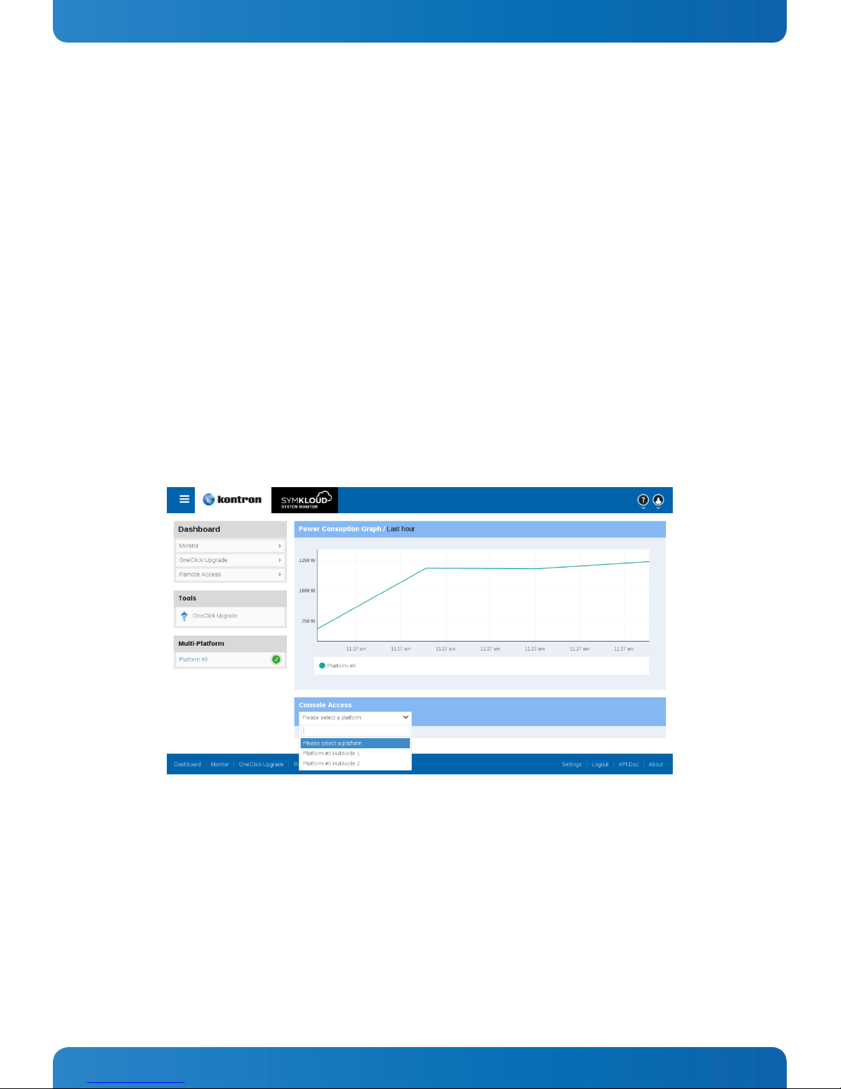
5.1 System Manager & System Monitor
The SYMKLOUD Shelf Manager hosts a monitoring, management and maintenance application called System Manager. The
functions of the System Manager are available through an API or a web interface. The System Monitor is the web interface also
hosted by the Shelf Manager. It provides a graphical representation of the features provided by System Manager's API.
The key features of the System Monitor are:
» Monitor system health
» System Maintenance (One-Click firmware upgrades)
» Access to switch configuration page
» Access to node KVM
NOTE: See the
this application
Kontron System Monitor User’s Guide
.
on the Kontron web site (www.kontron.com) for detailed information about
Figure 14: Main Page Overview

31
www.kontron.com
User’s Guide
“Chassis Health” Sensor State
Alarm Level
01h Healthy
No alarm (all alarm leds off)
02h Informational fault
No alarm (all alarm leds off)
03h Minor fault
Minor (MNR) led on (amber)
04h Major fault
Major (MJR) led on (red)
05h Critical fault
Critical (CRT) led on (red)
5.1.1 Platform Health Monitoring
Each node BMC and hub ShMC of the MS2900 platform implements a set of component “Health Status”. The “Health Sensor” of
each component aggregates the state of local sensors. The list of sensors for the nodes and hubs usually includes critical
voltage, temperature and discrete sensors. Please consult the associated User Guide for a detailed list of sensors members of
this aggregate for a specific node or hub.
Additionally ShMCs on the hub have a “Chassis Health” sensor. This sensor is an aggregation of all the “Health Status” sensors
of each component of the platform. The state of this sensor is replicated on the system control panel CRT, MJR and MNR LEDs.
The most critical “Health Status” sensor reading is displayed by the LEDs.
Here are the “Health Status” vs LEDs status reading table:
5.2 Management Subsystems
The MS2900 management software addresses all major subsystems within the platform, including platform management (IPMI),
cooling/thermal management, and power management.
5.2.1 Platform Management
The platform management subsystem is based on features of the Integrated Baseboard Management Controller (iBMC). This
subsystem consists of communication buses, sensors, system BIOS, and server management firmware. The platform
management subsystem also supports standard IPMI features as well as other features that are not part of IPMI. The supported
features are listed below.
IPMI 2.0 Features
» Baseboard Management Controller (BMC)
» IPMI Watchdog timer
» Messaging support, including command bridging and user/session support
» Chassis device functionality, including power/reset control and BIOS boot flags support
» Event receiver device: the BMC receives and processes events from other platform subsystems
» Field Replaceable Unit (FRU) inventory device functionality: the BMC supports access to system FRU devices using IPMI
FRU commands
» System Event Log (SEL) device functionality: the BMC supports and provides access to a SEL
» Sensor Data Record (SDR) repository device functionality: the BMC supports storage and access of system SDRs
» Sensor device and sensor scanning/monitoring: the BMC provides IPMI management of sensors and polls sensors to
monitor and report system health.

32
www.kontron.com
User’s Guide
» IPMI interfaces: host interfaces include System Management Software (SMS) with receive message queue support and
Server Management Mode (SMM)
IPMB Interface
» LAN interface that supports the IPMI-over-LAN protocol (RMCP, RMCP+)
» Serial-over-LAN (SOL)
» ACPI state synchronization: the BMC tracks ACPI state changes that are provided by the BIOS
» BMC self-test: the BMC performs initialization and run-time self-tests and makes results available to external entities
Non-IPMI Features
The integrated BMC also supports the following non-IPMI features:
» Fault Resilient Booting (FRB): FRB2 is supported by the Watchdog timer functionality
» Limited number of system resets for fan speed control
» Platform Environment Control Interface (PECI) thermal management support
» Memory thermal management
» Power supply unit management
Support for the power supply unit sensor: the BMC handles power-good dropout conditions
» Front panel management: the ShMC controls the system status LED and chassis ID LED
The chassis ID LED is turned on using an IPMI command
» Address Resolution Protocol (ARP): the BMC sends and responds to ARPs (supported on embedded NICs)
» Dynamic Host Configuration Protocol (DHCP): the BMC performs DHCP (supported on embedded NICs)
» Embedded web server
New Manageability Features
The SYMKLOUD MS2900 platform also offers some new features:
» Support for embedded web server UI in Basic Manageability feature set (i.e., fan monitoring, software upgrade, node
health/presence)
» Management support for PMBus rev1.2-compliant power supplies
5.2.2 Cooling and Thermal Management
MS2900 Airflow Path
The MS2900 platform cooling scheme is a front-to-back push configuration. Air is pushed into the chassis by the fans at the
front. Air then passes through the backplane assembly and is channeled into the node bays where it exits the system through the
node carrier grills. Figure 15 shows this air path.

33
www.kontron.com
User’s Guide
Figure 15: Air Path Through the System
This cooling push configuration pressurizes the system. With this configuration, dust can only enter the system by the fan inlet.

34
www.kontron.com
User’s Guide
Description
Power (W)
Quantity
Subtotal
(W)
MSH8900 Hub (without SFP+ modules)
15 2 30
MSU8700 Uplink Module (without SFP+ modules)
4 2 8
SFP+ Optical Module
0.7 2 1.4
60x60x38 Fan Module
33 5 165
MSP8020 Processor Node Module
82 9 738
Total power consumption (W)
9431
5.2.3 Power
Power consumption while running a stressed transcoding application (on MSP8020 Processor Nodes)
1
Measured with a stressed transcoding application; 25°C ambient temperature

35
www.kontron.com
User’s Guide
5.3 Buttons, Connectors and LEDs
This section covers the user-accessible connectors, cable requirements, and LED definitions.
5.3.1 LED Indicators
Figure 16 shows the locations of all MS2900 platform LEDs and the table explains the LED functions.
Figure 16: Front and Rear Panel LEDs

36
www.kontron.com
User’s Guide
LED State Definitions
Front Panel LEDs
Chassis/Control Panel
Color(s)
Description
Chassis ID LED
Blue
OFF
Whole chassis is ready to be pulled off-line
OR
All nodes are OFF (No payload) = On, blue
All nodes are on, payload power is on = Off
Power LED
Green
OFF
All nodes ON, payload power = On, green
Power state transition in progress (Power On or Power Off) =
Blinking, green
All nodes OFF, no payload power = Off
Alarm LEDs
(CRT, MJR, MNR)
MNR: Amber
MJR: Red
CRT: Red
OFF
Alarm = On
Alarm Description:
Minor fault (MNR): The system is not at risk and still runs within
its specifications.
Major fault (MJR): The system is at risk and requires immediate
attention. Major faults can be normal if the system in high stress
conditions, but should never be repetitive and permanent.
Critical fault (CRT): The system is at risk and requires immediate
action. A device might have already failed.
See section 5.1.1 for more details.
No alarm = Off
Hub 1 and Hub 2
Color(s)
Description
ID LED
Blue
OFF
Only management power is present = On, blue
ID command is active = Blinking, blue
Payload power is present = Off
Power/Active LED
Green
OFF
Payload power is on = On, green
Hub hosts active shelf manager = On, green
Hub hosts the inactive shelf manager = Blinking green
Payload power removed = Off
Status LED
Amber
OFF
Hub “not healthy”, needs attention = On, amber (default)
Hub transitioning when power button pressed
(clean shutdown request) = Blinking, amber
Hub operating under normal conditions = Off

37
www.kontron.com
User’s Guide
LED State Definitions
1Gbe RJ-45 (Quad/Management)
Color(s)
Description
LED1 Link Status/Activity
Green
OFF
Link established = On, green
Activity = Blinking, green
No link, no activity = Off
LED2 Link Speed
Green
Amber
OFF
Link speed 1 Gbit = On, green
Link speed 10 Mbit, 100 Mbit = On, amber
No link = Off
10GbE SFP+ Stacking,
10GbE SFP+ Uplink
Color(s)
Description
LED1
Green
OFF
Link established = On, green
Activity = Blinking, green
No link, no activity = Off
LED2
Amber
OFF
Fault = On, amber
Normal conditions, no fault = Off
Fan ID/Status
Color(s)
Description
LED
Amber
OFF
Maintenance needed = On, amber
Fan ID command active = Blinking, amber
Normal operating condition = Off
Back Panel LEDs
Hub Uplink
Color(s)
Description
LED1
Green
OFF
Link established = On, green
Activity = Blinking, green
No link, no activity = Off
LED2
Amber
OFF
Fault = On, amber
Normal conditions, no fault = Off
Processor Node
Color(s)
Description
Status LED
Red/Amber
OFF
Node not healthy, needs attention = On, red
Node in transition, power button pressed =
Blinking, amber
Node operating normally = Off

38
www.kontron.com
User’s Guide
LED State Definitions
Power LED
Green
OFF
Node on, payload present = On, green
Node in standby state (S3/S4 sleep state) =
Blinking, green
Node is off (no payload) = Off
ID LED
Blue
OFF
Management power on, but no payload = On, blue
Command active = Blinking, blue
Node is on or on standby (payload present) = Off
Power Supply
Color(s)
Description
AC/DC Input Status
Green
OFF
Line within range = On, green
Line under voltage = Off
DC Output
Yellow
Green
Both Yellow/Green
12V or Vsb1 out of regulation = On, yellow
Over temperature shutdown = On, yellow
Output over voltage = On, yellow
Regulation normal operation = On, green
Hot-Standby mode = Blinking, yellow 25%,
green 75%
Over temperature warning = Blinking, yellow 75%,
green 25%
Minor fan regulation error = Blinking, yellow 50%,
green 50%
1
Vsb – Standby Output (3V3)

39
www.kontron.com
User’s Guide
5.3.2 Cable Connections
The MS2900 platform provides I/O connections from both the front and rear of the chassis. In the front of the chassis there is a
10GbE SFP+ uplink port, a 10GbE SFP+ stacking port, and four 1GbE RJ-45 LAN ports for each hub. For the location of the front
panel ports, see Figure 5, “Front View.”
Rear Uplink modules provide the option of redirecting 10GbE/Stacking (per hub) to the rear.
Figure 17 shows the location of the two 10GbE uplink ports and two 10GbE stacking ports (one of each for each switch/ShMC
hub).
Figure 17: Rear Uplink Ports
For each hub there is also front panel access to an RJ-45 serial console port and a management RJ-45 Ethernet port. The
MS2900 platform ships with an RJ-45 to DB-9 serial adapter (included in the box – see Figure 18). This adapter can be used with
an RJ-45 cable to connect devices with a DB-9 serial port to the MS2900 via either hub RJ-45 console port (See Figure 5, “2” or
“7”).
Figure 18: RJ-45 to DB-9 Console Adapter

40
www.kontron.com
User’s Guide
Europe, Middle East & Africa
Lise-Meitner-Str. 3-5
86156 Augsburg
Germany
Tel.: +49 (0) 821 4086-0
Fax: +49 (0) 821 4086 111
info@kontron.com
North America
14118 Stowe Drive
Poway, CA 92064-7147
USA
Tel.: +1 888 294 4558
Fax: +1 858 677 0898
info@us.kontron.com
Asia Pacific
1~2F, 10 Building, No. 8
Liangshuihe 2nd Street,
Economical & Technological
Development Zone,
Beijing 100176, P.R.China
Tel.: + 86 10 63751188
Fax: + 86 10 83682438
info@kontron.cn
e.
Corporate Offices
 Loading...