

Page 1
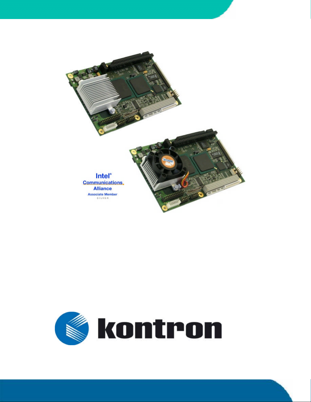
speedMOPSlcdCE
User’s Guide
Document Revision 1.2
Page 2

Page 3

KONTRON
i
CONTENTS
1. USER INFORMATION...............................................................................................1
1.1 About This Manual..........................................................................................1
1.2 Copyright Notice............................................................................................1
1.3 Trademarks...................................................................................................2
1.4 Standards ....................................................................................................2
1.5 Warranty......................................................................................................2
1.6 Technical Support ..........................................................................................3
2. INTRODUCTION .....................................................................................................4
2.1 speedMOPSlcdCE............................................................................................4
2.2 The speedMOPS Family ....................................................................................4
3. GETTING STARTED ..................................................................................................6
4. SPECIFICATIONS....................................................................................................7
4.1 Functional Specifications.................................................................................7
4.2 Mechanical Specifications................................................................................9
4.2.1. PC/104 Bus Connector (ISA part).................................................................9
4.2.2. PC/104-Plus Bus Connector (PCI part)...........................................................9
4.2.3. Dimensions.............................................................................................9
4.2.4. Height on Top..........................................................................................9
4.2.5. Height on Bottom.....................................................................................9
4.2.6. Weight ...................................................................................................9
4.3 Electrical Specifications ................................................................................10
4.3.1. Supply Voltage ...................................................................................... 10
4.3.2. Supply Voltage Ripple ............................................................................. 10
4.3.3. Supply Current (typical)........................................................................... 10
4.3.4. Supply Current (maximum)....................................................................... 11
4.3.5. Real-time Clock (RTC) Battery.................................................................... 11
4.4 MTBF......................................................................................................... 12
4.5 Environmental Specifications ......................................................................... 13
4.5.1. Temperature ......................................................................................... 13
4.5.2. Humidity.............................................................................................. 13
5. CPU, CHIPSET AND SUPER I/O ................................................................................14
5.1 CPU........................................................................................................... 14
5.2 Chipset ...................................................................................................... 15
5.2.1. GMCH (815E Chipset) .............................................................................. 15
5.2.2. ICH4 (82801DB)..................................................................................... 16
5.3 Super I/O ................................................................................................... 17
5.4 CPU, Chipset and Super-I/O Configuration......................................................... 17
6. SYSTEM MEMORY .................................................................................................18
7. ISA AND PCI BUS EXPANSION.................................................................................19
speedMOPSlcdCEUser’s Guide Contents
Page 4

KONTRON
7.1 PC/104 Bus (ISA part)................................................................................... 19
7.1.1. PC/104 Connectors ................................................................................. 19
7.1.2. PC/104 Configuration.............................................................................. 20
7.2 PC/104-Plus (PCI part) .................................................................................. 20
7.2.1. PC/104-Plus Connector............................................................................ 20
7.2.2. PC/104-Plus Configuration ....................................................................... 20
8. GRAPHICS INTERFACES .........................................................................................21
8.1 Video Controller .......................................................................................... 21
8.2 CRT Connector............................................................................................. 21
8.3 Flat Panel LVDS Interface (JILI) Connector ........................................................ 22
8.4 Display Power Considerations ......................................................................... 22
8.5 Connecting a LCD Panel ................................................................................. 23
8.6 Configuration.............................................................................................. 23
8.7 Graphics Technical Support ............................................................................ 23
8.8 Available Video Modes .................................................................................. 24
8.8.1. Standard IBM-Compatible VGA Modes ......................................................... 24
8.8.2. Extended VESA VGA Modes........................................................................ 24
9. SERIAL-COMMUNICATION INTERFACES..................................................................... 25
9.1 Connectors .................................................................................................25
9.2 Configuration.............................................................................................. 25
10. PARALLEL-PORT INTERFACE...................................................................................26
10.1 Connector .................................................................................................. 26
10.2 Configuration.............................................................................................. 27
11. KEYBOARD AND FEATURE INTERFACE .......................................................................28
11.1 Connector .................................................................................................. 28
11.2 Signal Descriptions ...................................................................................... 29
11.2.1. Example Connection AT-keyboard and Other Functions ................................ 30
11.3 Configuration.............................................................................................. 30
12. PS/2 MOUSE INTERFACE........................................................................................31
12.1 Connector .................................................................................................. 31
12.2 Configuration.............................................................................................. 31
13. USB INTERFACES .................................................................................................32
13.1 Connector .................................................................................................. 32
13.1.1. Limitations ........................................................................................ 32
13.2 Configuration.............................................................................................. 33
14. FLOPPY INTERFACE ..............................................................................................34
14.1 Connector .................................................................................................. 34
14.1.1. Connector Diagram ..............................................................................35
14.2 Configuration.............................................................................................. 35
15. IDE INTERFACES..................................................................................................36
Contents ii speedMOPSlcdCEUser’s Guide
Page 5

KONTRON
15.1 Connector .................................................................................................. 36
15.2 Configuration.............................................................................................. 37
16. ETHERNET INTERFACES ......................................................................................... 38
16.1 First Ethernet Controller................................................................................ 38
16.2 Second Ethernet Controller (optional).............................................................. 39
16.3 Connectors ................................................................................................. 40
16.4 Configuration.............................................................................................. 40
16.5 Ethernet Technical Support ............................................................................ 40
17. SOUND INTERFACE...............................................................................................41
17.1 Connector .................................................................................................. 42
17.2 Configuration.............................................................................................. 42
17.3 Technical Support for Sound........................................................................... 42
18. FAN INTERFACE ...................................................................................................43
18.1 Connector .................................................................................................. 43
18.2 Configuration.............................................................................................. 43
19. POWER INTERFACE...............................................................................................44
19.1 Main Power Connector................................................................................... 44
19.2 Auxiliary Power Connector ............................................................................. 44
19.3 Power Pins.................................................................................................. 45
19.4 Configuration.............................................................................................. 45
19.5 External Battery ................................................................ ..........................46
20. WATCHDOG TIMER ...............................................................................................47
20.1 Configuration.............................................................................................. 47
20.2 Programming .............................................................................................. 47
20.2.1. Initializing the WDT..............................................................................47
20.2.2. Triggering the WDT............................................................................... 47
21. HARDWARE MONITOR...........................................................................................48
21.1 Configuration.............................................................................................. 48
22. THERMAL MANAGEMENT ....................................................................................... 49
23. APPENDIX A: SYSTEM-RESOURCE ALLOCATION ...........................................................50
23.1 Interrupt Request (IRQ) Lines......................................................................... 50
23.2 Direct Memory Access (DMA) Channels.............................................................. 51
23.3 Memory Map ............................................................................................... 51
23.3.1. Using Expanded Memory Managers.......................................................... 52
23.4 I/O Address Map .......................................................................................... 53
23.5 Peripheral Component Interconnect (PCI) Devices............................................... 54
23.6 SM Bus Devices ............................................................................................ 54
24. APPENDIX B: BIOS OPERATION...............................................................................55
24.1 Determining the BIOS Version......................................................................... 55
speedMOPSlcdCEUser’s Guide Contents
Page 6

KONTRON
24.2 Configuring the System BIOS .......................................................................... 56
24.2.1. Start Phoenix BIOS Setup Utility ............................................................. 56
24.2.2. General Information............................................................................. 56
24.3 Main Menu .................................................................................................58
24.3.1. Master or Slave Submenus ..................................................................... 59
24.4 Advanced Menu ........................................................................................... 60
24.4.1. Advanced Chipset Control Submenu ......................................................... 60
24.4.2. PCI/PNP Configuration Submenu............................................................. 61
24.4.3. PCI Device, Slot #x Submenu .................................................................. 61
24.4.4. PCI/PNP ISA IRQ Resource Exclusion Submenu ...........................................62
24.4.5. Memory Cache Submenu........................................................................ 63
24.4.6. I/O Device Configuration Submenu.......................................................... 64
24.4.7. Keyboard Features Submenu .................................................................. 65
24.4.8. Hardware Monitor Submenu................................................................... 65
24.4.9. Watchdog Timer Settings Submenu..........................................................66
24.4.10. Display Control Submenu ......................................................................66
24.4.11. Miscellaneous Submenu ........................................................................ 67
24.5 Security Menu ............................................................................................. 68
24.6 Power Menu ................................................................................................ 69
24.6.1. Thermal Management Submenu .............................................................. 70
24.7 Boot Menu and Utilities................................................................................. 71
24.7.1. MultiBoot XP ...................................................................................... 71
24.7.2. Boot First Function .............................................................................. 72
24.8 Exit Menu ................................................................................................... 73
24.9 Kontron BIOS Extensions ............................................................................... 74
24.9.1. JIDA BIOS extension ............................................................................ 74
24.9.2. Remote Control Client Extension ............................................................. 74
24.9.3. LAN PXE ROM ...................................................................................... 75
24.10 Updating or Restoring BIOS Using PhoenixPhlash ............................................ 76
24.10.1. Flashing a BIOS................................................................................... 76
24.10.2. Preventing Problems When Updating or Restoring BIOS ............................... 77
25. APPENDIX C: BLOCK DIAGRAM ...............................................................................78
26. APPENDIX D: MECHANICAL DIMENSIONS..................................................................79
26.1 Board Dimensions and Mounting Holes ............................................................. 79
26.1.1. Top View ............................................................................................ 79
26.1.2. Side View ........................................................................................... 80
27. APPENDIX E: CONNECTOR LAYOUT...........................................................................81
27.1 Top Side ..................................................................................................... 81
27.2 Bottom Side ...............................................................................................82
27.3 Connector Functions and Interface Cables ......................................................... 83
27.4 Pin -out Table .............................................................................................. 84
28. APPENDIX F: PC ARCHITECTURE INFORMATION ..........................................................88
28.1 Buses ........................................................................................................ 88
Contents iv speedMOPSlcdCEUser’s Guide
Page 7

KONTRON
28.1.1. ISA, Standard PS/2 - Connectors ............................................................. 88
28.1.2. PC/104, PCI........................................................................................ 88
28.2 General PC Architecture................................................................................. 89
28.3 Ports......................................................................................................... 89
28.3.1. RS-232 Serial...................................................................................... 89
28.3.2. ATA .................................................................................................. 90
28.3.3. USB.................................................................................................. 90
28.4 Programming .............................................................................................. 90
29. APPENDIX G: DOCUMENT REVISION HISTORY.............................................................91
speedMOPSlcdCEUser’s Guide Contents
Page 8

KONTRON
Contents vi speedMOPSlcdCEUser’s Guide
Page 9

KONTRON
1. USER INFORMATION
1.1 About This Manual
This document provides information about products from KONTRON Embedded Computers AG
and/or its subsidiaries. No warranty of suitability, purpose, or fitness is implied. While every
attempt has been made to ensure that the information in this document is accurate, the
information contained within is supplied “as-is” and is subject to change without notice.
For the circuits, descriptions and tables indicated, KONTRON assumes no responsibility as far as
patents or other rights of third parties are concerned.
1.2 Copyright Notice
Copyright © 2005 KONTRON Embedded Computers AG.
All rights reserved. No part of this manual may be reproduced, transmitted, transcribed, stored in a
retrieval system, or translated into any language or computer language, in any form or by any
means (electronic, mechanical, photocopying, recording, or otherwise), without the express
written permission of KONTRON.
JUMPtecIndustrielle Computertechnik AG and KONTRON Embedded Computers AG merged in July
2002. JUMPtec is now known as KONTRON Embedded Modules GmbH. Products labeled and sold
under the KONTRON Embedded Modules name (formerly JUMPtec) are now considered KONTRON
products for all practical purposes, including warranty and support.
DIMM-PC®, PISA®, ETX Components SBC, JUMPtec®, and KONTRON Embedded Modules are
registered trademarks of KONTRON Embedded Modules GmbH©.
speedMOPSlcdCEUser’s Guide User Information
Page 10

1.3 Trademarks
The following lists the trademarks of components used in this board.
IBM, XT, AT, PS/2 and Personal System/2 are trademarks of International Business
Machines Corp.
Microsoft is a registered trademark of Microsoft Corp.
Intel is a registered trademark of Intel Corp.
All other products and trademarks mentioned in this manual are trademarks of their
respective owners.
1.4 Standards
KONTRON Embedded Modules is certified to ISO 9000 standards.
KONTRON
1.5 Warranty
This KONTRON Embedded Modules product is warranted against defects in material and
workmanship for the warranty period from the date of shipment. During the warranty period,
KONTRON Embedded Modules will at its discretion decide to repair or replace defective products.
Within the warranty period, the repair of products is free of charge as long as warranty conditions
are observed.
The warranty does not apply to defects resulting from improper or inadequate maintenance or
handling by the buyer, unauthorized modification or misuse, operation outside of the product’s
environmental specifications or improper installation or maintenance.
KONTRON Embedded Modules will not be responsible for any defects or damages to other products
not supplied by KONTRON Embedded Modules that are caused by a faulty KONTRON Embedded
Modules product.
User Information 2 speedMOPSlcdCE User’s Guide
Page 11
KONTRON
1.6 Technical Support
Technicians and engineers from KONTRON Embedded Modules and/or its subsidiaries and official
distributors are available for technical support. We are committed to making our product easy to
use and will help you use our products in your systems.
Before contacting KONTRON Embedded Modules technical support, pleaseconsult our Web site for
the latest product documentation, utilities, and drivers. If the information does not help solve the
problem, contact us by telephone.
Asia Europe North/South America
Kontron Embedded
Technology (Asia Pacific)
Kontron Embedded Modules GmbH Kontron America
Far East Science Park, 2nd
Floor No. 2, Lane 50, Nan
Kang Road Section 3, Nan
Kang District Taipei, Taiwan
Tel: +886-2-2782-0201 Tel: +49 (0) 991-37024-0 Tel: 888-294-4558
Fax: +886- 2-2782-7486 Fax: +49 (0) 991-37024-104 Fax: (858) 677-0898
Brunnwiesenstr. 16
94469 Deggendorf – Germany
6260 Sequence Drive
San Diego, CA 92121-4371
speedMOPSlcdCEUser’s Guide User Information
Page 12

2. INTRODUCTION
2.1 speedMOPSlcdCE
The speedMOPSlcdCE hosts either an ULV Intel® Celeron® processor or an LV Intel® Celeron®
processor in combination with an Intel®815E chipset that includes an integrated graphics
memory-controller hub. A SDRAM-SODIMM socket can hold either PC100 or PC133 SODIMM memory
modules up to 512MB. Two USB 2.0 ports and one 10/100 MBit Ethernet interfaces extend the
standard connectivity of two serial ports, one parallel port, a PS/2 mouse and keyboard interface.
The speedMOPSlcdCE is a member of Kontron Embedded Modules GmbH’s speedMOPS family.
2.2 The speedMOPS Family
Each speedMOPS modulefeatures the same pinout and interface for the following components and
peripherals:
KONTRON
PC/104 and PC/104+ connector
Sound
2xUSB 2.0
10 / 100BaseT Ethernet
Keyboard
PS/2 Mouse
VGA
RS232 serial port
LPT
FDC
IDE1 and IDE2
These family features allow the use of the same chassis over the whole product line and maximize
design reuse.
Introduction 4 speedMOPSlcdCE User’s Guide
Page 13

KONTRON
speedMOPSmodules allow the use of standard notebook SODIMM memory modules.
Display connections aresimplified when using the onboard standard JILI Interface (JUMPtec®
Intelligent LVDS Interface). JILI automatically recognizes which display is connected and
independently sets all video parameters. All speedMOPS modules are plug-and-work enabled to
further reduce time-to-market.
As part of the standard features package, allspeedMOPS modules come with a JUMPtec Intelligent
Device Architecture (JIDA) interface, which is integrated into the BIOS. This interface enables
hardware independent access to features that cannot be accessed via standard APIs. Functions such
as watchdog timer, brightness and contrast of LCD backlight, and user bytes in the EEPROM can be
configured with ease by taking advantage of this standard speedMOPS module feature.
The speedMOPS line products support the PC/104-Plus (PCI) and the PC/104 (ISA) standard via
Kontron’s own PCI-to-ISA bridge. Because of the availability of both extension buses, all past and
future PC/104 expansion assemblies with state-of-the-art processor performance can be
accommodated.
speedMOPSlcdCEUser’s Guide 5 Introduction
Page 14

3. GETTING STARTED
The easiest way to get the speedMOPSlcdCE board running is to use a starter kit from
Kontron Embedded Modules GmbH. Take the following steps:
1. Turn off the power supply (part of the starter kit).
2. Connect the power supply to the starter kit baseboard (part of the starter kit).
3. Plug a suitable SDRAM memory module into the SODIMM socket of the speedMOPS.
4. Plug the speedMOPS to the PC/104 and PC/104Plus bus connectors on the starter kit
baseboard.
5. Make all necessary connections from the speedMOPS to the starter kit board. (the cables come
with the starter kit). The starter kit board offers various interfaces on standard connectors.
KONTRON
6. Connect the CRT monitor to the CRT interface or a LCD panel to the JILI interface by using the
corresponding adapter cable.
7. Plug a keyboard to the starter kit’s keyboard connector.
8. Connect the floppy drive (part of the starter kit) with the data cable (part of the starter kit) to
the speedMOPS floppy interface.
9. Connect the power supply to the floppy’s power connector.
10. Plug a hard-drive data cable to the speedMOPS hard-disk interface. Attach the hard disk to the
connector at the opposite end of the cable.
11. If necessary, connect the power supply to the hard disk’s power connector.
12. Make sure all your connections have been made correctly.
13. Turn on the power.
14. Enter the BIOS by pressing the F2 key during boot-up. Make all changes in the BIOS setup. See
the BIOS chapter of this manual for details.
Getting Started 6 speedMOPSlcdCE User’s Guide
Page 15

KONTRON
4. SPECIFICATIONS
4.1 Functional Specifications
Processor
ULV Intel® Celeron® @ 400MHz or LV Intel® Celeron® @ 733MHz
1GHz LV Celeron available only upon request andis not RoHS compliant (lead-free)
Chipset
Intel® 815E Chipset graphics memory-controller hub
Power Supply
+5V-only
Super I/O
Winbond W83627HF
Cache
On-die 256KB second level cache
Memory
One 144-pin SODIMM interface that runs insynchronous (133/133) mode and in
pseudo-synchronous (133/100) mode with FSB133 3.3V PC-133 or PC-100 unbuffered
SDRAM, up to 512MB
Two Serial Ports (COM A and COM B)
RS232Cserial ports (10-pin headers)
16550-compatible
One Parallel Port (LPT1)
Enhanced Parallel Port (EPP) and Extended CapabilitiesPort (ECP) with bi-directional
capability
Floppy Interface
Enhanced Intelligent Drive Electronics (EIDE)
Two Peripheral Component Interconnect (PCI) Bus Master IDE ports (up to 4 devices)
speedMOPSlcdCEUser’s Guide 7 Specifications
Page 16

Universal Serial Bus (USB)
2 USB 2.0 ports
USB legacy keyboard support
USB floppy, CDROM, USB stick boot support
Ethernet Controller
Integrated Intel® 82562 10/100BASE-T LAN
Follows the common criteria of the embedded technology market segment
Onboard Video Graphics Array (VGA)
Intel® 815E Chipset graphics memory controller hub
CRT (Cathode Ray Tube)
LCD (Liquid Crystal Display) flat panel 24bit LVDS interface that uses JILI
Audio
Integrated Intel® SoundBlaster™AC97
Windows Sound System™compatible
Phoenix BIOS, 1024KB Flash BIOS
KONTRON
NV-EEPROM for CMOS Setup Retention without Battery
PS/2 Keyboard Controller
PS/2 Mouse Controller
Watchdog Timer (WDT)
Real Time Clock (RTC) with Onboard Battery Supply
Specifications 8 speedMOPSlcdCE User’s Guide
Page 17

KONTRON
4.2 Mechanical Specifications
4.2.1. PC/104 Bus Connector (ISA part)
One 2 X 32 pin stackthrough and one 2 X 20 pin stackthrough connector
4.2.2. PC/104-Plus Bus Connector (PCI part)
One 4 x 30 pin 2mm stackthrough connector
The PC/104plus connector does not have a connector shroud. This mechanical limitation does not
reduce the functionality of a speedMOPSlcdCE board.
4.2.3. Dimensions
Length x Width:96mm x 147mm (3,8" x 5,8")
4.2.4. Height on Top
Maximum31.25mm (1.23”)
Height is depending upon CPU cooler/fan.
4.2.5. Height on Bottom
Maximum10.67mm (0.42”) including PC/104plus connectors
4.2.6. Weight
About 195g (full featured version without SDRAM-SODIMM)
speedMOPSlcdCEUser’s Guide 9 Specifications
Page 18
4.3 Electrical Specifications
4.3.1. Supply Voltage
+5V DC +/- 5%
4.3.2. Supply Voltage Ripple
100mV peak to peak 0- 20MHz
4.3.3. Supply Current (typical)
The speedMOPSlcdCE is equipped with power-saving features. Different power-consumption tests
were executed to give an overview of the electrical conditions for several operational states. The
board used a 256MB SDRAM module for test results shown below. An attached hard disk was not
supplied through the measurement path, and there was no extension module in the system.
KONTRON
speedMOPSlcdCE400MHz
Operational State @ +5V
DOS Prompt 2.60A
DOS Standby 2.02A
Windows Idle 2.12A
Windows 3D performance 3.03A
Windows 100% CPU Load 2.44A
speedMOPSlcdCE733MHz
Operation State @ +5V
DOS Prompt 3.28A
DOS Standby 2.30A
Windows Idle 2.38A
Windows 3D performance 3.84A
Windows 100% CPU Load 3.31A
speedMOPSlcdCE 1GHz
Operational State @ +5V
DOS Prompt 3.83A
DOS Standby 2.47A
Windows Idle 2.55A
Windows 3D performance 4.49A
Windows 100% CPU Load 3.89A
Specifications 10 speedMOPSlcdCEUser’s Guide
Page 19

KONTRON
4.3.4. Supply Current (maximum)
Board @ +5V
speedMOPSlcdCE 400MHz 3.79A
speedMOPSlcdCE 733MHz 4.81A
speedMOPSlcdCE 1GHz 5.61A
(Calculated theoretical values from all components maximum supply currents)
4.3.5. Real-time Clock (RTC) Battery
Voltage range: 2.0 - 4.0V (typ 3.0V)
Quiescent current: max. 3,5uA@ 3.0 V
speedMOPSlcdCEUser’s Guide 11 Specifications
Page 20

4.4 MTBF
The following MTBF (Mean Time Between Failure) values were calculated using a combination of
manufacturer’stest data (if the data was available) and a Bellcore calculation for the remaining
parts. The Bellcore calculation involved the “Method 1 Case 1” method. In that particular method,
the components were assumed to be operating at a 50% stress level in a 40° C ambient
environment, and the systemwas assumed to have not been burned in. Manufacturer’s data was
used wherever possible. The manufacturer’s data, when used, was specified at 50° C, which means
that the following resultswere slightly conservative. The MTBF values shown below were for a 40° C
office or telecommunications environment. Higher temperatures and other environmental stresses
(extreme altitude, vibration, and salt water exposure) will lower the MTBF values.
System MTBF (hours) : 184220
Notes: Fans shipped with Kontron Embedded Modules GmbH products have an
KONTRON
operating life of up to 50,000 hours.
The estimates above assumed that a passive heat-sinking arrangement was
used instead of a fan.
Estimated RTC battery life (as opposed to battery failures) was not accounted for
in the above figures and needs separate consideration. Battery life depends on
temperature and operating conditions. When the Kontron unit uses external
power, the battery drain comes from leakage paths.
Specifications 12 speedMOPSlcdCEUser’s Guide
Page 21

KONTRON
4.5 Environmental Specifications
4.5.1. Temperature
The IntelCeleronis specified for proper operation when the junction temperature is within the
specified range of 0C to 100C.
The Intel®815E chipset temperature runs at a maximum of 100°C . The Intel®ICH4 I/O Controller
Hub 4 (82801DB) case temperature runs at a maximum of 110C.
The processor protects itself from catastrophic overheating by use of an internal thermal sensor at a
temperature level of approximately 135°C.
Operating: 0 to +60 C (*) (with appropriate airflow)
Non-operating: -10 to +85 C (non-condensing)
Note: (*) The maximum operating temperature is the maximum measurable
temperature on any spot on the module’s surface. You must maintain the
temperature according to the above specification.
4.5.2. Humidity
Operating: 10% to 90% (non-condensing)
Non-operating: 5% to 95% (non-condensing)
speedMOPSlcdCEUser’s Guide 13 Specifications
Page 22

5. CPU, CHIPSET AND SUPER I/O
5.1 CPU
The speedMOPSlcdCE is available with an Intel®LV/ULV Celeron®central processing unit (CPU) at
speedsof either 400MHz or 733MHz.
IntelLV/ULV Celeron®CPU features include:
Supportfor the Intel Architecture with Dynamic Execution
On-die primary 16-Kbyte instruction cache and 16-Kbyte write-back data cache
On-die second level cache (256-Kbyte) with Advanced Transfer Cache Architecture
Data Pre-fetch Logic
KONTRON
Integrated math co-processor
Support for MMX™technology
Support for Streaming SIMD Extensions
Power-Management Features, including Quick Start, Deep Sleep and Deeper Sleep
modes, which provide low-power dissipation
CPU, Chipset and Super I/O 14 speedMOPSlcdCEUser’s Guide
Page 23

KONTRON
5.2 Chipset
The chipset of thespeedMOPSlcdCEconsists of the Intel®815E chipset GMCH (Graphics and Memory
Controller Hub) and the Intel®82801DB ICH-4 (I/O Controller Hub 4).
5.2.1. GMCH (815E Chipset)
Processor/Host Bus Support
Intel® Pentium® III processor and Intel® Celeron®
Supports processor’s 370-Pin Socket
Supports 32-Bit System Bus Addressing
4 deep in-order queue; 4 or 1 deep request queue
In-order and Dynamic Deferred Transaction Support
66/100/133MHz System Bus Frequency
GTL+ I/O Buffer
Integrated SDRAM Controller
32MB to 512MB using 16Mb/64 Mb/128Mb/256Mb technology
64-bit data interface
100/133MHz system memory bus frequency
Support for Asymmetrical SDRAM addressing only
Support for x8 and x16 SDRAM device width
Unbuffered,non-ECC SDRAM only supported
Refresh Mechanism: CBR ONLY supported
Enhanced Open page arbitration SDRAM paging scheme
Integrated Graphics Controller
3D Hyper Pipelined Architecture
Full 2D H/W Acceleration
Motion Video Acceleration
Mip Maps with Trilinear and Anisotropic Filtering
85MHz Flat-Panel Monitor/Digital CRT Interface Or Digital Video
Integrated 24-bit 230MHz RAMDAC
Gamma Corrected Video
DDC2B Compliant
Up to 1600x1200 in 8-bit Color at 85Hz Refresh
Hardware Accelerated Functions
3 Operand Raster Bit BLTs
64x64x3 Color Transparent Cursor
Power-Management Functions
Stop Clock Grant and Halt special cycle translation from the host to the hub interface
APM compliant power management
speedMOPSlcdCEUser’s Guide 15 CPU, Chipset and Super I/O
Page 24

5.2.2. ICH4 (82801DB)
PCI 2.2 Bus interface at 33MHz
Integrated LAN controller
WfM 2.0 and IEEE802.3 compliant
10/100 Mbit/s Ethernet support
USB
Three UHCI USB 1.1 or one EHCI high speed USB 2.0 host controller(s)
Supports up to 6 ports (4 available on EPIC board’s front;2 internal)
AC-Link for AC’97 support
Integrated IDE controller
Ultra ATA33 and PIO mode support
Two channels for up to4 devices with independent timing
Interrupt Controller
KONTRON
Two cascade 83C59 with 15 interrupts
Enhanced DMA
Two cascaded 8237 controllers
Supports PC/PCI DMA and LPC DMA
Supports DMA collection buffers
Timers based on 82C54
Power-Management Logic
APM compliant
Supports PCI PME#
Low Pin Count (LPC) interface
SM(System Management) Bus 2.0 interface
CPU, Chipset and Super I/O 16 speedMOPSlcdCEUser’s Guide
Page 25

KONTRON
5.3 Super I/O
A super I/O Winbond W83627HFdevice is connected to the LPC (Low Pin Count) Bus. This device
provides the following additional features:
Twoserial ports (RS232)
One Multi-Mode Parallel Port
Floppy Disk Controller
PS/2-Keyboard and PS/2-Mouse Interface
5.4 CPU, Chipset and Super-I/O Configuration
See the Advanced Menu and its submenus section in the Appendix B: BIOS chapter for information
on setting choices.
speedMOPSlcdCEUser’s Guide 17 CPU, Chipset and Super I/O
Page 26

6. SYSTEM MEMORY
The speedMOPSlcdCE uses a 144-pin Small Outline-Dual Inline Memory Modules (SODIMM) on the
bottom side of the board. One socket is available for 3.3 Volt (power level) un-buffered PC-133 or
PC-100 Synchronous Dynamic Random Access Memory (SDRAM) of 8, 16, 32, 64, 128, 256 or
512MB.
The total amount of memory available on the SDRAM module is used for main memory and graphics
memory on thespeedMOPSlcdCE. TheUnified Memory Architecture (UMA) manages how the system
shares memory between the graphics controller and the processor. The full system memory size is
not available for software applications. In legacy mode, up to 1MB of system memory is used for
graphics memory. The graphics-controller driver of the operating system can extend the amount of
video memory to amaximum of 32MB.
KONTRON
System Memory 18 speedMOPSlcdCEUser’s Guide
Page 27

KONTRON
7. ISA AND PCI BUS EXPANSION
The design of the speedMOPSlcdCE offers ISA- and PCI-bus signals on PC/104 and PC/104-Plus
connectors. The PC/104-Plus standard is downward compatible with PC/104 and enables the use of
standard PC/104 and PC/104-Plus adapter cards.
7.1 PC/104 Bus (ISA part)
The PC/104 bus consists of two connectors that use 104 pins in total.
XT bus connector (64 pins)
AT bus connector (40 pins, which is optional for 16-bit, data-bus system)
The pin-out of the PC/104 bus connectors corresponds to the pin-out of the ISA bus connectors
with some added ground pins. The two PC systems with different form factors are electrically
compatible.
The XT bus connector, Row A and B.
The corresponding 64-pin female header (ISA bus = 62pins) has two added ground pins at the end
of the connector (Pin A32 and Pin B32). The pin-out between PC/104 bus and XT ISA bus is identical
between A1- A31 and B1 - B31.
The AT bus extension connector, Row C and D.
The corresponding 40-pin female header (ISA bus = 36 pins) has four added ground pins, including
two on each side of the connector. To avoid confusion, the first two pins are defined as Pin C0 and
Pin D0. The additional ground pins at the end of the connector are defined as C19 and D19. The pin-
out between PC/104 bus and AT ISA bus is identical between C1 - C18 and D1 - D18.
7.1.1. PC/104 Connectors
The speedMOPSlcdCE features the XT bus and AT bus extension on two, dual-row socket connectors
with a 2.54mm x 2.54mm grid (0.1" x 0.1").
The PC-104 bus is available through Connectors J6B and J6C. To find the location of the connectors
see the Appendix E: Connector Layout chapter.
A description of the signals, including electrical characteristics and timings is beyond the scope of
this document. Please refer to the official ISA bus and PC/104 specifications for more details.
speedMOPSlcdCEUser’s Guide 19 ISA and PCI Bus Expansions
Page 28

7.1.2. PC/104 Configuration
When using add-on boards on the PC/104 bus, make sure that there are no resource conflicts in the
system. Carefully choose hardware interrupts, DMA channels, and memory and I/O address ranges
to avoid resource conflicts, which are often the reason for a board or a feature not functioning
correctly. See Appendix A: System Resource Allocation for information about the resources already
used by thespeedMOPSlcdCE.
7.2 PC/104-Plus (PCI part)
The speedMOPSlcdCE offers the PC/104-Plus bus on a quad-row female connector with a 2mm x
2mm (0.79” x 0.79”) pitch. This connector implements the standard 32-bit PCI bus signals.
7.2.1. PC/104-Plus Connector
You can use PC/104-Plus adapter boards on the top and on the bottom of a speedMOPSlcdCE’s
stackthrough connector. The PC/104plus connector does not have a connector shroud. If you
intend to use +3.3V powered PC/104plus adapter cards, the +3.3V has to be supplied separately
because it is not generated onboard the speedMOPSlcdCE.
KONTRON
The PC/104-Plus bus is available through Connector J8. To find the location of the connectors see
the Appendix E: Connector Layout chapter.
A description of signals, including electrical characteristics and timings, is beyond the scope of this
document. Please refer to the official PCI bus and PC/104-Plus specifications for more details.
7.2.2. PC/104-Plus Configuration
Add-on boards on the PC/104-Plus bus have to be associated to a “PCI-slot.” Make sure that there
are no resource conflicts in the system. Carefully choose PCI interrupts, REQ/GNT pairs, and IDSEL
for the add-on board. See the technical manual of the add-on board for more details.
The speedMOPSlcdCE’s PCI bus can be configured to optimize your system. See the PCI
Configuration Submenu in Appendix B: BIOS for more information on configuration.
ISA andPCI Bus Expansions 20 speedMOPSlcdCEUser’s Guide
Page 29
KONTRON
8. GRAPHICS INTERFACES
8.1 Video Controller
The speedMOPSlcdCE uses the graphics accelerator integrated in the Intel® 815E chipset. It
delivers high performance 2D, 3Dand video capabilities. With its interface to UMA (Unified Memory
Architecture), up to 1MB of legacy system memory is used as video memory. The video memory can
be extended to 32MB by the use of the available “Intel® Extreme Graphics” drivers.
The controller can drive two interfaces with its graphics engines on the speedMOPSlcdCE:
Cathode Ray Tube (CRT) interface
Low Voltage Differential Signaling (LVDS) interface
8.2 CRT Connector
The CRT monitor interface is available through the J2 connector (6 pins). To fin d the location of the
connectors see the Appendix E: Connector Layout chapter.To have the signals available on a
standard DSUB-15 CRT monitor connector, an adapter cable is required. A 15-pin DSUB cable is
available from Kontron (KAB-VGA-2, Part Number 96053-0000-00-0).
The following table shows the pin-out of the CRT connector.
Header Pin Signal Name Function DSUB-25
1 RED Analog video red 1
2 GRN Analog video green 2
3 BLU Analog video blue 3
4 GND Signal ground 7
5 VSYNC Vertical sync 14
6 HSYNC Horizontal sync 13
speedMOPSlcdCEUser’s Guide 21 Graphic Interfaces
Page 30

8.3 Flat Panel LVDS Interface (JILI) Connector
The interface for the LCD Panel is available through Connector J1 (40 pins) on the bottom side of
the board. To find the location of the LCD Panel interface connector, please see the Appendix E:
Connector Layout chapter.
This connector represents the JILI interface (JUMPtec Intelligent LVDS Interface). The
implementation of this subsystem complies with the JILI Specification from Kontron Embedded
Modules GmbH. This supports the JILI3 implementation. A variety of cables for different display
types are available from Kontron. Please refer to the actual cable list on the Kontron Web site for
part numbers and cable names. A detailed description of the JILI interface standard also is
available in a separate document JILIM???.PDF. The three question marks represent the documents
revision number. You can download this document from the Kontron Web site, or contact your local
Kontron technical support to receive it.
8.4 Display Power Considerations
When using a LCD Panel, additional voltages may be required to drive the display’s logic and to
supply the backlight converter and the contrast voltage.
KONTRON
The display logic may require +5V for standard or +3.3V for low-power LCDs. Contrast voltages for
passive displays are normally very different and can range from –30V to +30V. Backlight converters
usually are +5V or +12V types. When using a Kontron JILI cable, you do not need to determine the
configuration. Display logic voltage and contrast voltage come pre-configured on the JILI cable. On
occasion, the backlight voltage has to be adjusted on the cable.
Even though the speedMOPSlcdCE also is available as a +5V-only board, you need to supply the
+12V for the backlight converter when using such a converter type.
The onboard 3.3V-circuitry of the speedMOPSlcdCE and the +3.3V logic voltage of low-voltage
panels are powered by separate voltage regulators. The one for the LCD is mounted on the JILI
adapter cable.
Graphic Interfaces 22 speedMOPSlcdCEUser’s Guide
Page 31

KONTRON
8.5 Connecting a LCD Panel
To determine whether your panel display is supported, check the Kontron Web site for panel lists.
We regularly update the list of panels that have been tested with our boards.
Many panel adapters for a wide spread variety of displays are available through Kontron. If you use
one of those adapters supplied by Kontron, configuration is easy:
1. Check whether you have the correct adapter and cable for the panel you plan to use. Inspect
the cable for damages.
2. Disconnect the power from your system.
3. Connect the panel adapterto the LCD Panel connector (JILI) on the speedMOPSlcdCE.
4. Connect the other end of the cable to your display.
5. Connect the backlight converter.
6. Supply power to your system.
7. If no image appears on your display, connect a CRT monitor to the CRT connector.
8. If necessary program the EEPROM on the JILI cable with the matching configuration data.
9. If you still do not see improvement, consider contacting the dealer for technical support.
8.6 Configuration
You can set the general configuration for the graphics controller in the BIOS setup utility. Refer to
the Advanced Chipset Control submenu and the Display Control submenu in the Appendix B: BIOS
Operation chapter for more configuration information.
You can download available drivers for the graphics controller from the Kontron Web site. For
further information read the read-me or help files or contact technical support.
8.7 Graphics Technical Support
If problems occur, you can solve some of them by using the latest drivers for the graphics
controller. Kontron provides you withthe latest tested drivers, which can differ from newer ones.
For further technical support, contact either Kontron, or obtain support information and
downloadable software updates from Intel®.
speedMOPSlcdCEUser’s Guide 23 Graphic Interfaces
Page 32
8.8 Available Video Modes
The following list shows the video modes supported by the graphics controller with their maximum
legacy frame-buffer size. When configured for smaller frame buffers and/or using a LCD panel on
the JILI interface, not all of the video modes listed below may be available. Capability depends on
the system configuration and on the display. Different operating systems also may not support all
listed modes by the available drivers.
8.8.1. Standard IBM-Compatible VGA Modes
Video Mode Type Characters/Pixels Colors/Gray val.
00h/01h Text 40x25 16
02h/03h Text 80x25 16
04h/05h Graphics 320x200 4
06h Graphics 640x200 2
0Dh Graphics 320x200 16
0Eh Graphics 640x200 16
0Fh Graphics 640x350 Mono
10h Graphics 640x350 16
11h Graphics 640x480 2
12h Graphics 640x480 16
13h Graphics 320x200 256
KONTRON
8.8.2. Extended VESA VGA Modes
VESA Display Pixels Colors
100h Graphics 640x400 256
101h Graphics 640x480 256
102h Graphics 800x600 16
103h Graphics 800x600 256
105h Graphics 1024x768 256
109h Text 132x25 16
10Ah Text 132x43 16
10Bh Text 132x50 16
10Ch Text 132x60 16
10Eh Graphics 320x200 64K
110h Graphics 640x480 32K
111h Graphics 640x480 64K
112h Graphics 640x480 16M
113h Graphics 800x600 32K
114h Graphics 800x600 64K
11Ch Text 128x37 16
11Dh Graphics 320x200 256
127h Graphics 640x400 64K
128h Graphics 640x400 16M
Graphic Interfaces 24 speedMOPSlcdCEUser’s Guide
Page 33
KONTRON
9. SERIAL-COMMUNICATION INTERFACES
Two fully functional serial ports (COMA and COMB) provide asynchronous serial communications.
COMA and COMB support RS-232 operation modes. They are 16550 high-speed UART compatible and
support 16-byte FIFO buffers for transfer rates from 50baud to 115.2Kbaud.
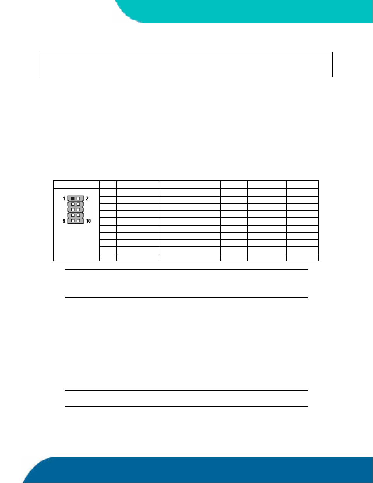
9.1 Connectors
COMA is available through the J14 connector (10 pins) and COMB through the J13 connector (10
pins). To have the signals available on the standard serial interface connectors DSUB9 or DSUB25,
anadapter cable is required. A 9-pin DSUB cable is available from Kontron (KAB-DSUB9-2, Part
Number 96017-0000-00-0). The following table shows the pinouts for COMA and COMB, as well as
necessary connections for DSUB adapters.
Header Pin Signal Name Function In / Out DSUB-25 DSUB-9
1 /DCD Data Carrier Detect In 8 1
2 /DSR Data Set Ready In 6 6
3 RxD Receive Data In 3 2
4 /RTS Request to Send Out 4 7
5 TxD Transmit Data Out 2 3
6 /CTS Clear to Send In 5 8
7 /DTR Data Terminal Ready Out 20 4
8 /RI Ring Indicator In 22 9
9 GND Signal Ground -- 7 5
10 VCC * +5V -- -- --
Notes: (*) To protect the external power lines of peripheral devices, make sure that:
-- the wires have the right diameter to withstand the maximum available current
-- the enclosure of the peripheral device fulfils the fire-protecting requirements of
-- IEC/EN 60950.
To find the location of the serial ports on the board, please see the Appendix E: Connector Layout
chapter.
9.2 Configuration
You can set the two serial input/output interfaces to a variety of I/O addresses and IRQ
configurations. Settings are changeable from the BIOS menu. Refer to the I/O Device Configuration
submenu in the Appendix B: BIOS Operation chapter for configuration information.
Note: Most operating systems detect the serial port with the I/O address 3F8h as
COM1 and 2F8h as COM2.
speedMOPSlcdCEUser’s Guide 25 Serial Communicatio Interfaces
Page 34
10. PARALLEL-PORT INTERFACE
The speedMOPSlcdCE incorporates a parallel port that can be set to uni-directional and supports
EPP and ECP operating modes.
10.1 Connector
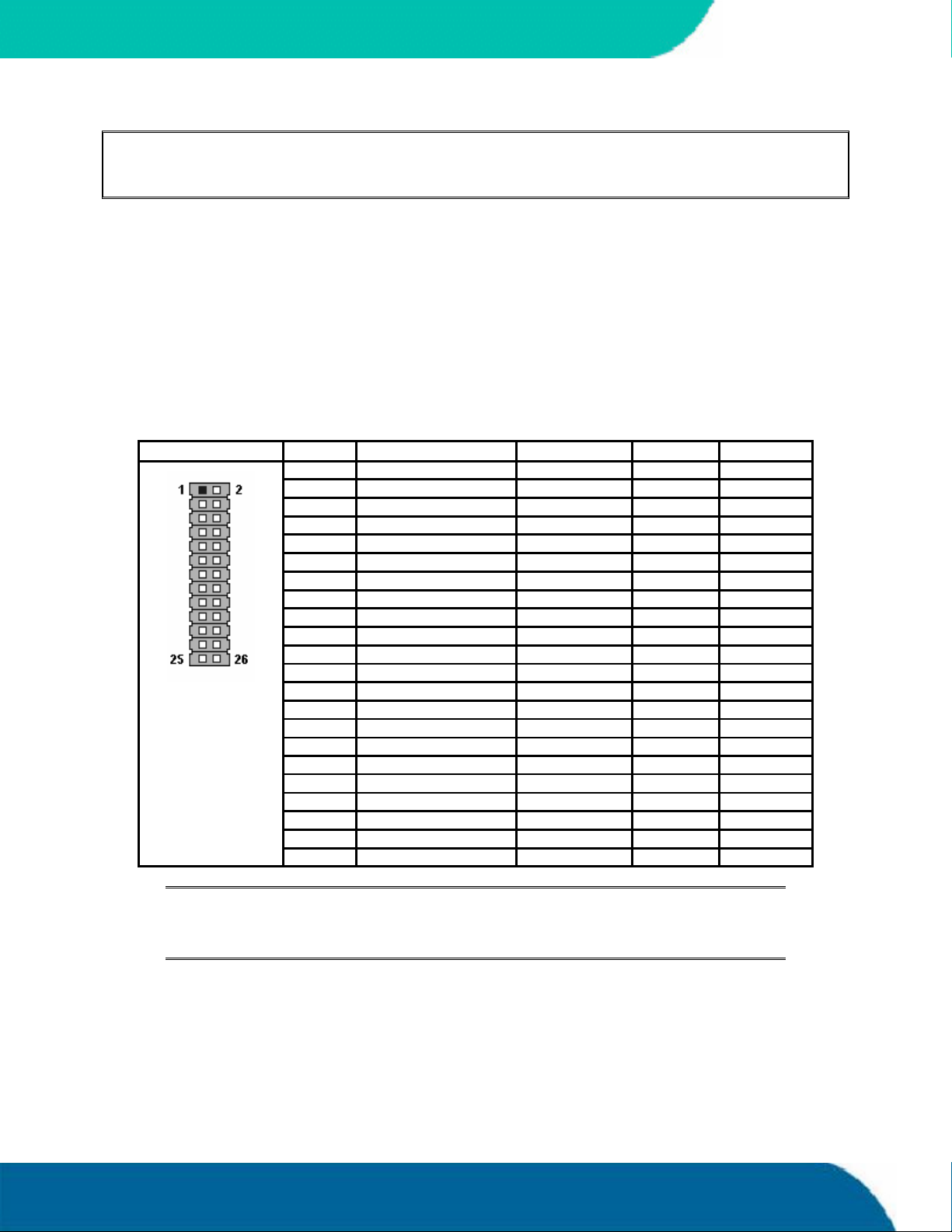
The parallel port is available through the X6 connector (26 pins). To have the signals available on a
standard, parallel-interface connector DSUB-25, an adapter cable is required, which is offered by
Kontron (KAB-DSUB25-1, Part Number 96015-0000-00-0).
The following table shows the pinout as well as necessary connections for a DSUB-25 adapter.
Header Pin Signal Name Function In / Out DSUB-25
1 /STB Strobe Out 1
3 PD0 Data 0 I/O 2
5 PD1 Data 1 I/O 3
7 PD2 Data 2 I/O 4
9 PD3 Data 3 I/O 5
11 PD4 Data 4 I/O 6
13 PD5 Data 5 I/O 7
15 PD6 Data 6 I/O 8
17 PD7 Data 7 I/O 9
19 /ACK Acknowledge In 10
21 /BUSY Busy In 11
23 PE Paper out In 12
25 /SLCT Select out In 13
2 /AFD Autofeed Out 14
4 /ERR Error In 15
6 /INIT Init Out 16
8 /SLIN Select in Out 17
26 VCC * + 5 V -- NC
10,12 GND Signal Ground -- 18 - 25
14,16 GND Signal Ground -- 18 - 25
18,20 GND Signal Ground -- 18 - 25
22,24 GND Signal Ground -- 18 - 25
KONTRON
Notes: (*) To protect the external power lines of peripheral devices, make sure that:
-- the wires have the right diameter to withstand the maximum available current
-- the enclosure of the peripheral device fulfils the fire-protecting requirements of
-- IEC/EN 60950.
To find the location of the parallel port on the board, please see the Appendix E: Connector Layout
chapter.
Parallel Port Interface 26 speedMOPSlcdCEUser’s Guide
Page 35

KONTRON
10.2 Configuration
The parallel-port mode, I/O addresses, and IRQs are changeable in the BIOS Setup Utility. You can
program the base I/O-address 378h, 3BCh, 278h, disable the interface or set it to AUTO. You can
choose IRQ5 or IRQ7 as the parallel-port interrupt. In ECP mode, you can choose DMA 1 or DMA 3.
Refer to the I/O Device Configuration Submenu in the Appendix B: BIOS Operation chapter for
additional informationon configuration.
speedMOPSlcdCEUser’s Guide 27 Parallel Port Interface
Page 36
11. KEYBOARD AND FEATURE INTERFACE
The keyboard and feature connector of the speedMOPSlcdCE offers five functions. The interface
connects the following:
Keyboard
Keyboard lock switch
Speaker
Battery
Reset button
KONTRON
11.1 Connector
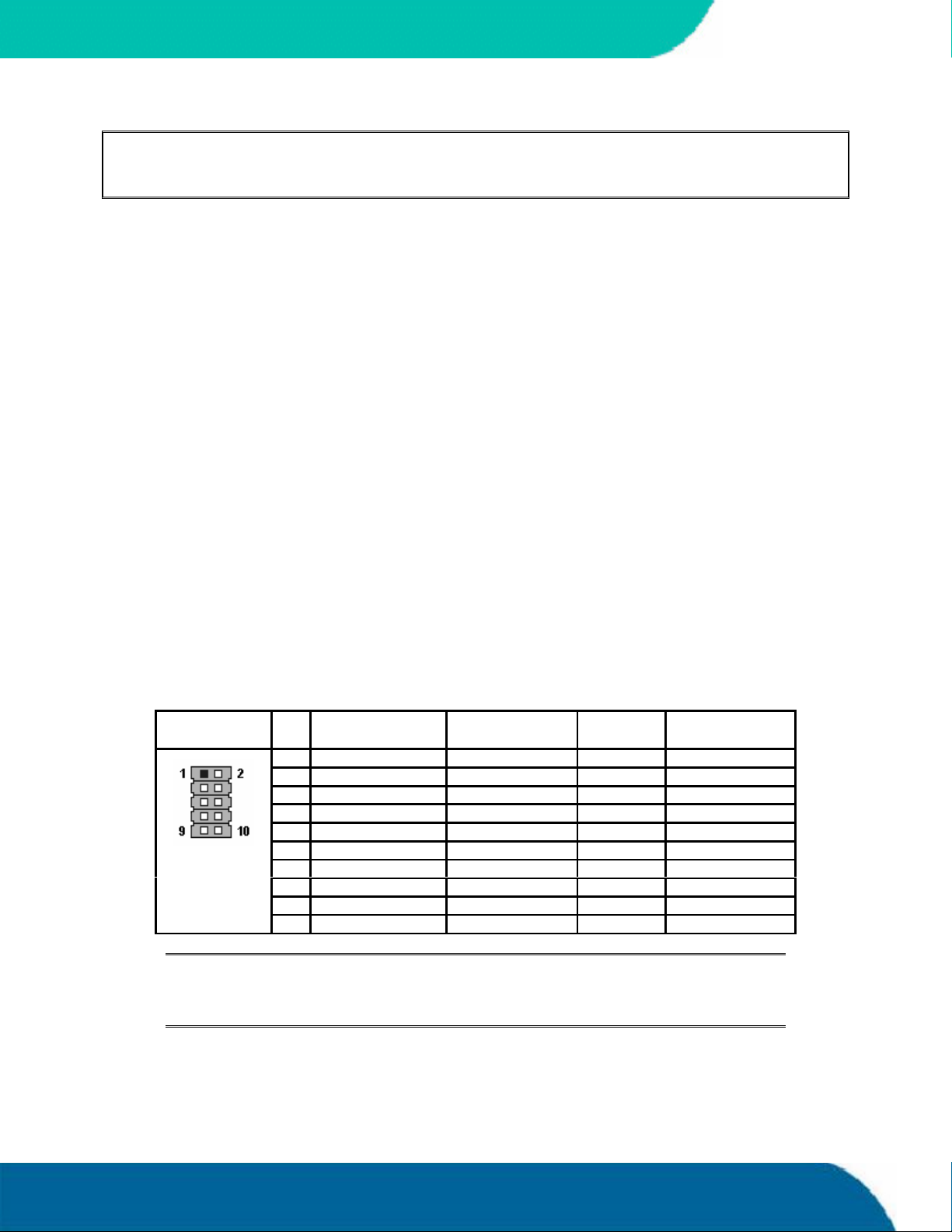
The keyboard and feature connector is available through Connector J12 (10 pins). An adapter cable
is required to connect a standard keyboard to this interface. There are two adapter cables available
from Kontron. One can be used for AT-keyboard (KAB-KB-1, Part Number 96023-0000-00-0), the
other for PS/2-keyboard (KAB-KB-PS2, Part Number 96060-0000-00-0). The adapter cables do not
know the other functions on this interface.
The following table shows the pinout as well as necessary connections for adapters.
Header Pin Signal Name Function 5-pin Din
Notes: (*) To protect the external power lines of peripheral devices, make sure that:
-- the wires have the right diameter to withstand the maximum available current
-- the enclosure of the peripheral device fulfils the fire-protecting requirements of
-- IEC/EN 60950.
6-pin MiniDin
(Diode)
1 Speaker Speaker output
2 GND Ground
3 /RESIN Reset input
4 /KBLOCK Keyboard lock
5 KBDAT Keyboard data 2 1
6 KBCLK Keyboard clock 1 5
7 GND Ground 4 3
8 VCC * +5V 5 4
9 BATT Battery in (3,0V)
10 PWRGOOD Powergood
(PS2)
To find the location of the keyboard and feature connector on the board, please see the Appendix E:
Connector Layout chapter.
Keyboard and Feature Interface 28 speedMOPSlcdCE User’s Guide
Page 37

Kontron
11.2 Signal Descriptions
/KBLOCK (Keyboard Lock)
Input on CPU modules
Output on any other module
Input to the keyboard controller input Port 1, Bit 7
/RESIN and PWRGOOD (Reset Inputs)
Input on CPU modules
When POWERGOOD goes high, it starts the reset generator on the CPU module to pull
the onboard reset line high after a valid reset period. You also can use this pin as a low
active hardware reset for modules.
Speaker
Open collector output on modules that drive a piezo electronic speaker.
Input on modules that connects a 5V piezo electronic speaker to this pin.
An 8-Ohm loudspeaker also can be connected between SPEAKER and GND, but because
of current limitation the volume will be low.
Connect only one speaker to this pin. The CPU usually drives this pin. However, other
modules also can use this signal to drive the system speaker.
KBDAT (Keyboard Data)
Bi-directional I/O pin on CPU modules
Keyboard data signal
KBCLK (Keyboard Clock)
Bi-directional I/O pin on CPU modules
Keyboard clock signal
speedMOPSlcdCEUser’s Guide 29 Keyboard and Feature Interface
Page 38
BATT (System Battery Connection)
This pin connects a system battery to all modules.
The battery voltage has to be higher than 2.2V and lower than 4.5V. A 3V battery is
recommended.
A battery is not needed to hold CMOS setup data. Your configurations for hard disks,
floppy drives, and other peripherals are saved in an onboard EEPROM. However, you
need a battery to save the CMOS date and time when power supply is turned off.
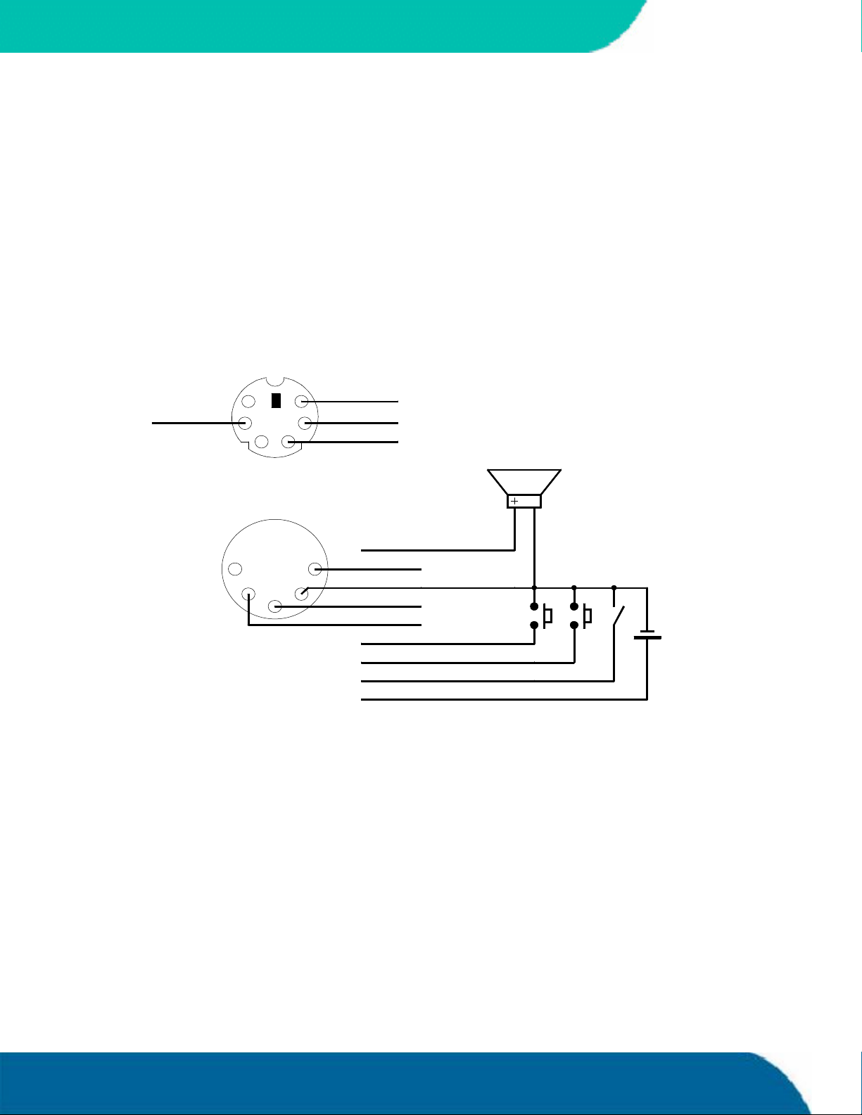
11.2.1. Example Connection AT-keyboard and Other Functions
6 PIN MINI-DIN
(PS/2 STYLE)
KONTRON
6 5
(+5V Vcc)
4
5 PIN DIN 180°
(DIN41524)
3
5
2
12
11.3 Configuration
Refer to the Keyboard Features submenu in the Appendix B: BIOS chapter for information on
configuration of the keyboard interface.
(KBCLK)
3
1
4
(GND)
(KBDAT)
(Speaker)
(KBCLK)
(GND)
(KBDAT)
(+5V Vcc)
(PWRGOOD)
(/RESIN)
(/KBLOCK)
(BATT)
Keyboard and Feature Interface 30 speedMOPSlcdCE User’s Guide
Page 39
Kontron
12. PS/2 MOUSE INTERFACE
The superI/O controller of the speedMOPSlcdCE supports a PS/2 mouse.
12.1 Connector
The PS/2 mouse interface is available on Connector J11 (4 pins). An adapter cable is required to
connect a standard PS/2 mouse. The cable is available from Kontron (KAB-MOUSE-PS2, Part Number
96062-0000-00-0).
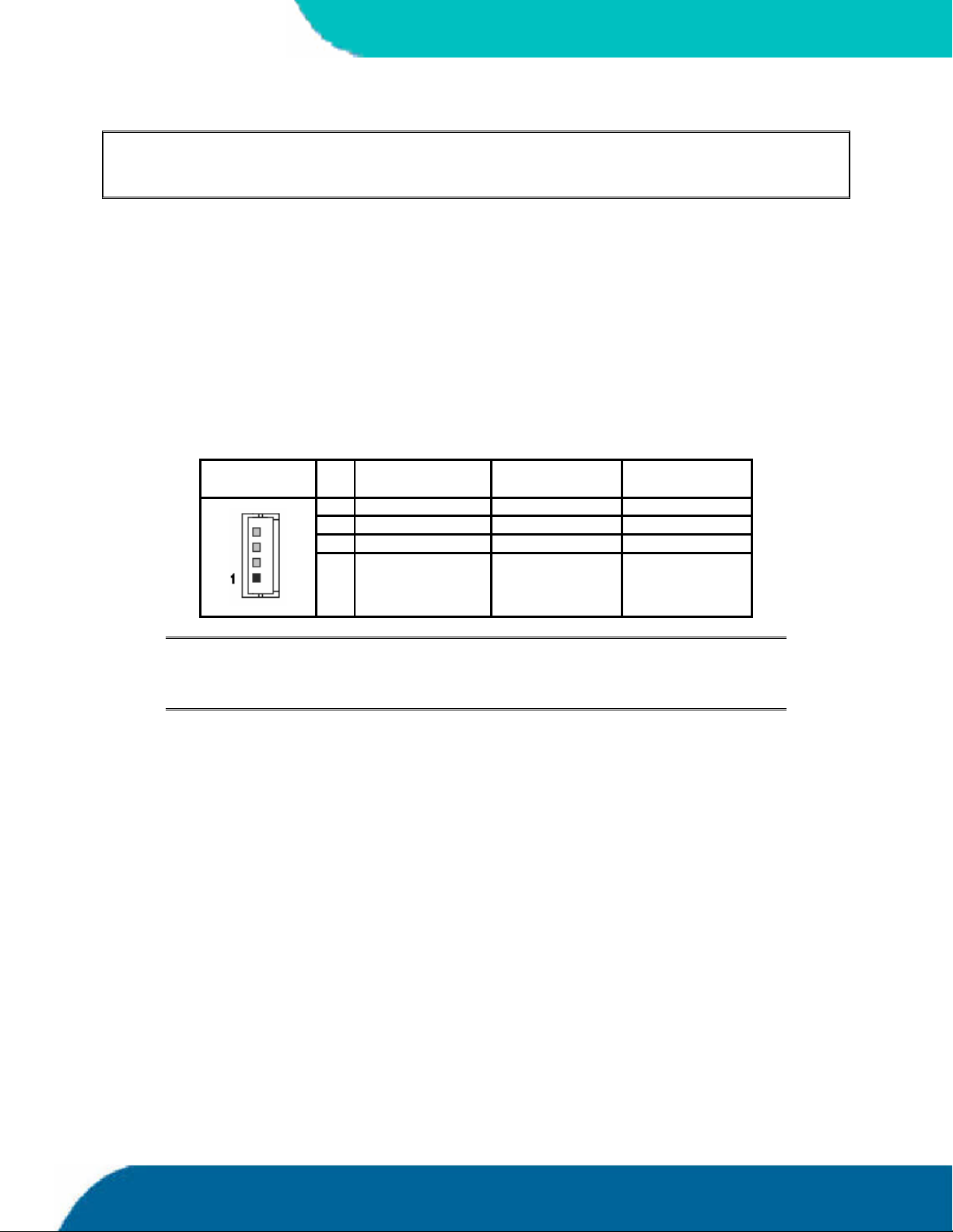
The following table shows the pinout and connections for a PS/2 mouse adapter.
Header Pin Signal Name Function 6-pin MiniDin
1 MSDAT Mouse data 1
2 VCC * +5V 4
3 GND Ground 3
4 MSCLK Mouse clock 5
(PS2)
Notes: (*) To protect the external power lines of peripheral devices, make sure that:
-- the wires have the right diameter to withstand the maximum available current
-- the enclosure of the peripheral device fulfils the fire-protecting requirements of
-- IEC/EN 60950.
To find the location of the PS/2 mouse connector on the board, please see the Appendix E:
Connector Layout chapter.
12.2 Configuration
You can set the PS/2 mouse to enabled, disabled or autodetect from the BIOS Setup. If you enable
the mouse, the IRQ12 is used as the interrupt and is no longer available for other devices. Please
refer to the Advanced Menu in the Appendix B: BIOS chapter for additional information on
configuration.
speedMOPSlcdCEUser’s Guide 31 PS/2 Mouse Interface
Page 40
13. USB INTERFACES
The speedMOPSlcdCE comes with two USB 2.0 ports, which you can expand by adding external hubs.
You can connect up to 127 USB peripherals.
13.1 Connector
The USB ports are available through the J17 and the J18 connectors (4 pins) each. To find the
location of the USB ports on the speedMOPSlcdCE board, please see the Appendix E: Connector
Layout chapter. To have the signals available on the standard USB interface connectors, an adapter
cable is required. A USB interface cable is available from Kontron (KAB-USB-1, Part Number 960540000-00-0).
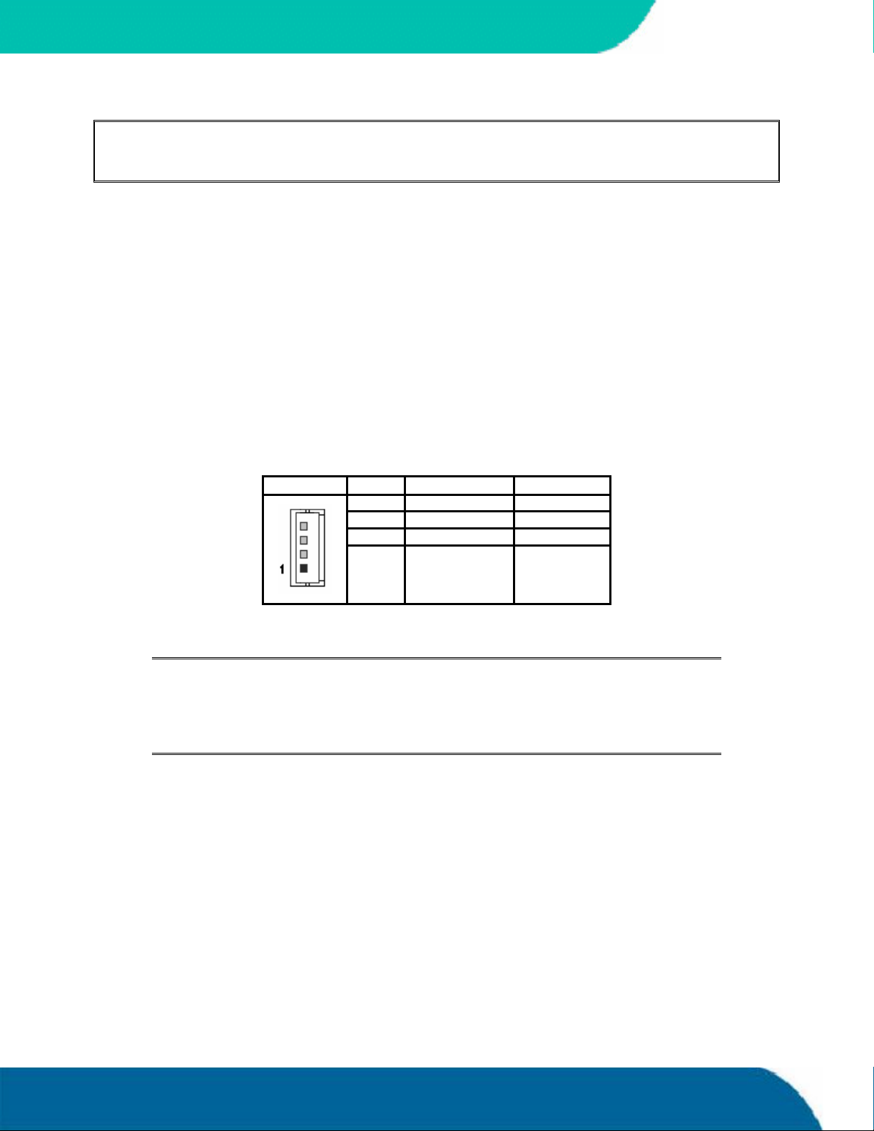
The following table shows the pinouts for the USB connector.
KONTRON
Notes: (*) To protect the external power lines of peripheral devices, make sure that:
13.1.1. Limitations
The power contacts for USB devices on Pin 1 and Pin 4 are not protected. They are suitable to supply
connected USB devices with a maximum of 500mA power dissipation. Do not supply external USB
devices with higher power dissipation through these pins. Always use a fuse when powering
external USB devices through these pins, otherwise a defective USB device may damage the
speedMOPSlcdCE. Kontron recommends using a resettable fuse, which follows the USB 1.1
specification, for power on external USB connectors.
Header Pin Signal Name Function
1 VCC * +5V
2 USB0 USB3 USB1 USB+
4 GND Ground
-- the wires have the right diameter to withstand the maximum available current
-- the enclosure of the peripheral device fulfils the fire-protecting requirements of
-- IEC/EN 60950.
The USB power lines are not protected. An additional resetable fuse is
recommended.
USB Interfaces 32 speedMOPSlcdCE User’s Guide
Page 41

Kontron
13.2 Configuration
You can enable or disable the USB UHCI Host Controller in the BIOS Setup Utility for support of USB
1.1 devices.
For high-speed USB 2.0 support of the two ports, enable the USB EHCI Host Controller.
You also can enable or disable the legacy USB support. Legacy support is required for a USB
keyboard anda USB Mouse when used with non USB aware operating systems such as Unix or DOS.
It also is required to boot from USB mass storage devices. For more information, see the I/O Device
Configuration Submenu section in Appendix B: BIOS Operation.
You can download available drivers or get driver download support information from the Kontron
Web site. Kontron offers the latest Kontron-tested drivers, which can differ from newer ones. For
further technical questions, contact your local support or get support information and
downloadable software updates from Intel®.
Notes: 1. Some operating systems without USB 2.0 support do not work well with
EHCI controller enabled. If you install such an OS at this board please
disable the EHCI controller in the Setup Utility before installation.
2. For operating systems not listed on our Web site please contact your OS
distributor for an USB 2.0 driver.
Kontron is not allowed by law to ship USB 2.0 drivers.
speedMOPSlcdCEUser’s Guide 33 USB Interfaces
Page 42
14. FLOPPY INTERFACE
The floppy-drive interface of the speedMOPSlcdCE uses a 2.88MB super I/O floppy-disk controller
and can support one floppy disk drive with densities that range from 360kB to 2.88MB.
14.1 Connector
The floppy disk interface is available on the flat-foil Connector X1 (26 pins). To find the location of
floppy-drive interface on the speedMOPSlcdCE board, please see the Appendix E: Connector Layout
chapter. This type of connector is often internally used in notebooks to connect a slim-line floppy
drive.
Accessories are available for this interface from Kontron. To connect a standard 3.5” floppy drive,
use an adaptercable (ADA-FLOPPY-2, Part Number 96001-0000-00-0). If you have a slim-line 3.5”
floppy drive, you may need a flat foil cable (KAB-FLOPPY/MOPS-1, Part Number 96019-0000-00-0).
It also is possible to get a slim line 3.5” floppy drive with cable from Kontron (FLOPPY-MOPS-1, Part
Number 96010-0000-00-0).
KONTRON
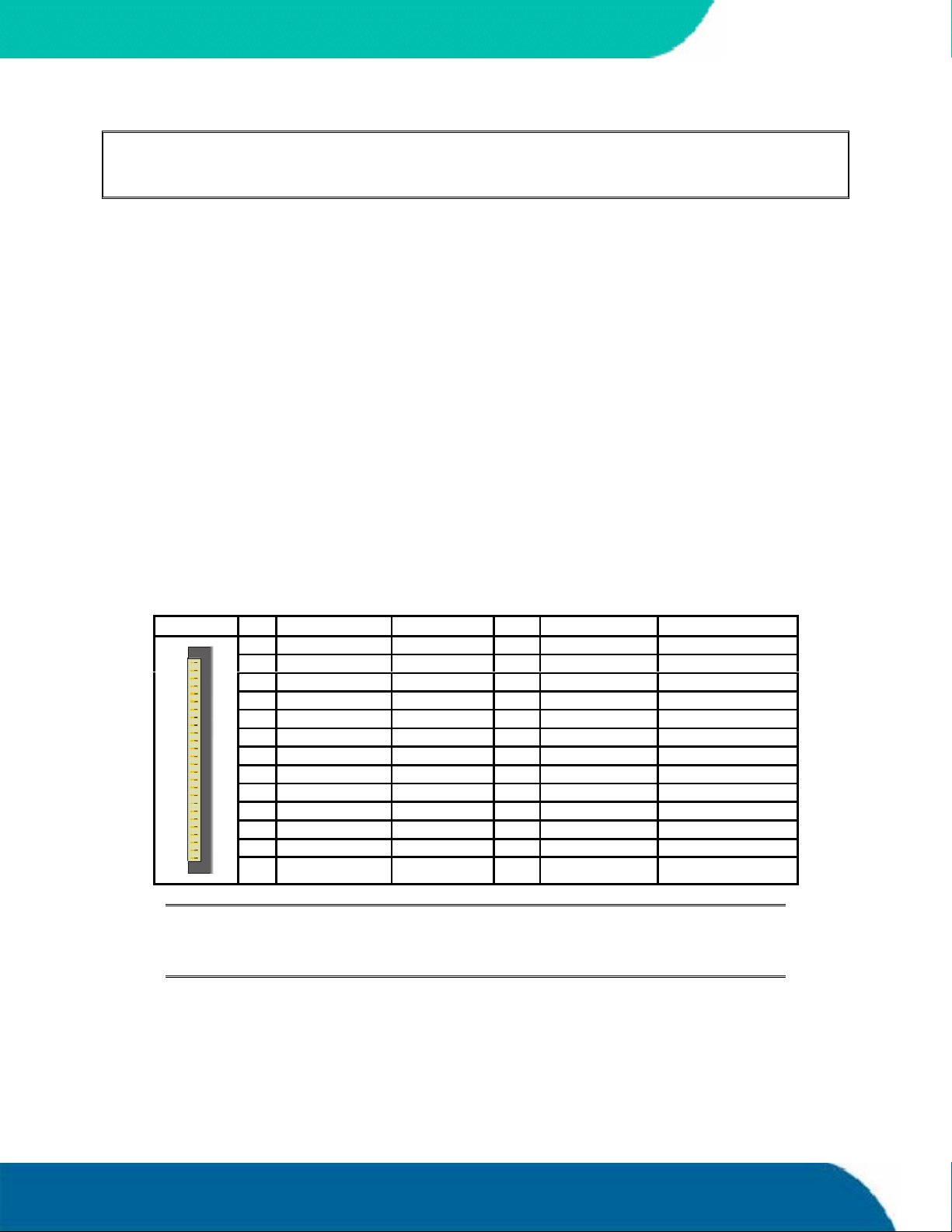
The following table shows the connector pin-out.
Header Pin Signal Name Function Pin Signal Name Function
1 VCC * +5V 2 /IDX Index
1
Notes: (*) To protect the external power lines of peripheral devices, make sure that:
3 VCC * +5V 4 /DR0 Drive Select 0
5 VCC * +5V 6 /DSKCHG Disk Change
7 NC Not connected 8 NC Not connected
9 NC Not connected 10 /MTR0 Motor on 0
11 NC Not connected 12 /FDIR Direction Select
13 NC Not connected 14 /STEP Step
15 GND Ground 16 /WDATA Write Data
17 GND Ground 18 /WGATE Write Gate
19 GND Ground 20 /TRK0 Track 00
21 GND Ground 22 /WRTPRT Write Protect
23 GND Ground 24 /RDATA Read Data
25 GND Ground 26 /HDSEL Side One Select
-- the wires have the right diameter to withstand the maximum available current
-- the enclosure of the peripheral device fulfils the fire-protecting requirements of
-- IEC/EN 60950.
Floppy Interface 34 speedMOPSlcdCEUser’s Guide
Page 43
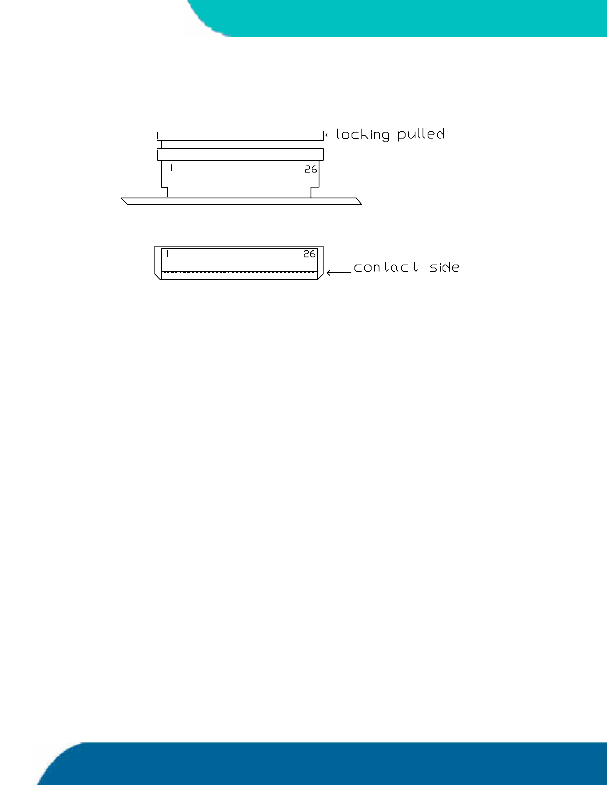
KONTRON
14.1.1. Connector Diagram
14.2 Configuration
You can configure the floppy disk interface in the BIOS Setup Utility. You can choose the 3.5”
(common) or 5.25” drive types with densities of 360kB, 720kB, 1.2MB, 1.25MB, 1.44MB or 2.88MB.
Refer to the Main Menu and the Miscellaneous Menu section of the Appendix B: BIOS Operation
chapter for more information on configuring the floppy drive.
You also can disable the floppy-disk interface in the I/O Device Configuration Submenu.
speedMOPSlcdCEUser’s Guide 35 Floppy Interface
Page 44

15. IDE INTERFACES
The speedMOPSlcdCE features two EIDE interfaces (Ultra DMA 33 mode) that can drive up to four
hard disks. When two devices share a single adapter, they are connected in a master/slave, daisychain configuration.
15.1 Connector
The IDE interfaces are available through Connector J15 (IDE1 - 44 pins) and J16 (IDE2 - 44 pins). To
find the location of the connectors see the Appendix E: Connector Layout chapter. These interfaces
are designed in 2mm grid for optimal connectivity to a 2.5” hard disk.
There are several accessories available for IDE connectivity.
KONTRON
You can use two cables to directly connect a hard disk in a 2.5” form factor (KAB-IDE-2MM, Part
Number 96021-0000-00-0) or a 3.5” form factor (KAB-IDE-25, Part Number 96020-0000-00-0).
You can plug a Kontron chipDISK, which is an IDE hard disk that uses Flash technology, into the IDE
interface. You also can use a chipDISK adapter (chipDISK-ADA1, Part Number 96004-0000-00-0) or
compact Flash adapter (CFC-ADA1, Part Number 96004-0000-00-2) for more disk support.
IDE Interfaces 36 speedMOPSlcdCE User’s Guide
Page 45
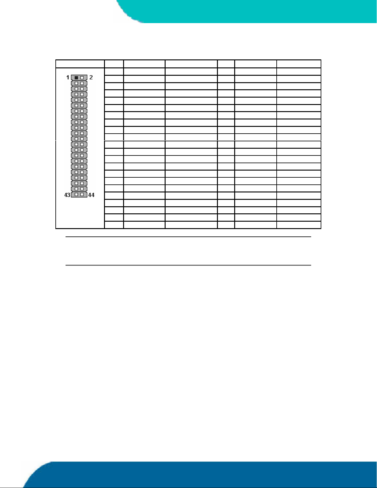
KONTRON
The following table shows the pin-out of the two IDE connectors.
Header Pin Signal Name Function Pin Signal Name Function
1 /RESET Reset 2 GND Ground
3 HDD7 Data 7 4 HDD8 Data 8
5 HDD6 Data 6 6 HDD9 Data 9
7 HDD5 Data 5 8 HDD10 Data 10
9 HDD4 Data 4 10 HDD11 Data 11
11 HDD3 Data 3 12 HDD12 Data 12
13 HDD2 Data 2 14 HDD13 Data 13
15 HDD1 Data 1 16 HDD14 Data 14
17 HDD0 Data 0 18 HDD15 Data 15
19 GND Ground 20 Key (NC) Key pin
21 DRQ IDE DMA Request 22 GND Ground
23 /IOW I/O write 24 GND Ground
25 /IOR I/O read 26 GND Ground
27 IOCHRDY I/O channel ready 28 CSEL Cable select
29 /AKJ Acknowledge 30 GND Ground
31 SIRQ Interrupt 32 NC Not connected
33 SA1 Addr 1 34 NC Not connected
35 SA0 Addr 0 36 SA2 Addr 2
37 /CS1 Chip select 1 38 /CS3 Chip select 3
39 NC Not connected 40 GND Ground
41 VCC (*) +5V 42 VCC (*) +5V
43 GND Ground 44 NC Not connected
Notes: (*) To protect the external power lines of peripheral devices, make sure that:
-- the wires have the right diameter to withstand the maximum available current
-- the enclosure of the peripheral device fulfils the fire-protecting requirements of
-- IEC/EN 60950.
To find the location of IDE-controller interfaces on the speedMOPSlcdCE board, please see the
Appendix E: Connector Layout chapter.
15.2 Configuration
The IDE interface offers several configuration settings. Refer to the “I/O Device Configuration
Submenu” section in the “Appendix B: BIOS Operation” chapter for additional information on
configuration.
speedMOPSlcdCEUser’s Guide 37 IDE Interfaces
Page 46

16. ETHERNET INTERFACES
The speedMOPSlcdCE can come with two Ethernet interfaces. However the second Ethernet interface
is optional and not equipped on every version of this product. The first Ethernet interface uses the
ICH4’s integrated 32-bit PCI LAN controller in combination with the Intel® 82562 platform LAN
connect device. The second Ethernet interface uses a Single Chip Fast Ethernet NIC Controller from
Davicom (DM9102A/DM9102DE).
The two network controllers support a 10/100Base-T interface. The devices auto-negotiate the use
of a 10Mbit/sec or 100Mbit/sec connection.
All major network-operating systems and several real-time and embedded operating systems
support the interface.
KONTRON
16.1 First Ethernet Controller
Intel® 82562 features include:
IEEE 802.3 10Base-T/100Base-TX Compliant Physical Layer Interface
IEEE 802.3u Auto-Negotiation Support
IEEE 802.3x Full Duplex Flow Control Standard
Digital Adaptive Equalization Control
Link Status Interrupt Capability
10Base-T auto-polarity correction
Platform LAN Connect Interface Support
Diagnostic Loopback Mode
1:1 transmit transformer ratio support
Low power (less than 300mW in active transmit mode)
Reduced power in “unplugged mode”
Note: The Ethernet interface works according to the common criteria of the embedded
technology market segment.
Ethernet Interfaces 38 speedMOPSlcdCEUser’s Guide
Page 47

KONTRON
16.2 Second Ethernet Controller (optional)
The Davicom DM9102A provides the following features:
Integrated Fast Ethernet MAC, Physical Layer, and transceiver on one chip
Compliance with PCI Specification 2.2
PCI-bus-master architecture
EEPROM 93C46 interface supports node ID, access-configuration information
Compliance with IEEE 802.3u 100Base-TX and 802.3 10Base-T
Compliance with IEEE 802.3u autonegotiation protocol for automatic link- type
selection
Full-duplex/half-duplex capability
Support IEEE 802.3x Full Duplex Flow Control
Digital clock recovery circuit using advanced digital algorithm to reduce jitter
High-performance 100Mbps clock generator and data-recovery circuit
Loopback mode for easy system diagnostic
Note: The Ethernet interface works according to the common criteria of the embedded
technology market segment.
speedMOPSlcdCEUser’s Guide 39 Ethernet Interfaces
Page 48
16.3 Connectors
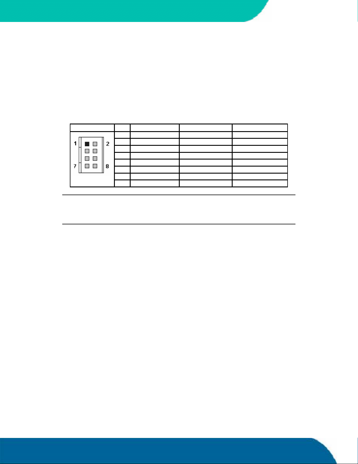
The Ethernet interfaces are available through connectors J4 and J5 (each 8 pins). The first Ethernet
controller serves J4 and the second optional Ethernet controller J5.
To have the signals of the Ethernet connection available on a standard RJ45 connector, you need an
adapter cable, which is offered by Kontron (KAB-MOPS-ETN1, Part Number 96048-0000-00-0).
The following table shows the pinout.
Header Pin Signal Name Function In/Out
KONTRON
1 TXD+ 10BASE-T Transmit Differential Output
2 TXD- 10BASE-T Transmit Differential Output
3 RXD+ 10BASE-T Receive Differential Input
4 SHLDGND Shield ground
5 SHLDGND Shield ground
6 RXD- 10BASE-T Receive Differential Input
7 SHLDGND Shield ground
8 SHLDGND Shield ground
Notes: TXD+, TXD- differential-output pair drives 10 and 100Mb/s Manchester-encoded
data to 100/10BASE-T transmit lines.
RXD+, RXD- differential input pair receives 10 and 100Mb/s Manchester-
encoded data from 100/10BASE-T receive lines.
To find the location of the Ethernet interfaces on the board, please see the Appendix E: Connector
Layout chapter.
16.4 Configuration
The onboard LAN controllers can be enabled or disabled from the BIOS Setup Utility. You also can
enable the onboard LAN PXE boot ROM to allow the system to boot-up via a network connection
from a PXE boot server. Refer to the I/O Device Configuration Submenu in the Appendix B: BIOS
Operation chapter for additional information on configuration.
You can download available drivers from the Kontron Web site. For further information read the
read-me file or contact technical support.
16.5 Ethernet Technical Support
You can solve some problems by using the latest drivers for both LAN controllers. Kontron provides
you with the latest Kontron-tested drivers, which can differ from newer ones. For further technical
support, contact either Kontron or get support information and downloadable software updates
from Intel® and Davicom.
Ethernet Interfaces 40 speedMOPSlcdCEUser’s Guide
Page 49

KONTRON
17. SOUND INTERFACE
The speedMOPSlcdCE uses a Realtek ALC650 sound codec. The ALC650 is an 18-bit, full duplex AC’97
2.2 compatible stereo audio CODEC designed for PC multimedia systems, including host/soft audio
and AMR/CNR based designs. The ALC650 incorporates proprietary converter technology to achieve
a high SNR, greater than 90 dB.
All major operating systems support the interface.
The ALC650 features:
High-performance CODEC with high S/N ratio (>90 dB)
18-bit ADC and 20-bit DAC resolution
Compliant with AC’97 2.2 Specifications
18-bit stereo full-duplex CODEC with independent and variable sampling rate
One analog line-level stereo input with 5-bit volume control: LINE_IN, (CD_IN is possible)
Stereo Output with 5-bit volume control
MIC input
Power-management capabilities
Embedded 50mW/20ohm OP at front LINE output
speedMOPSlcdCEUser’s Guide 41 Sound Interface
Page 50
17.1 Connector
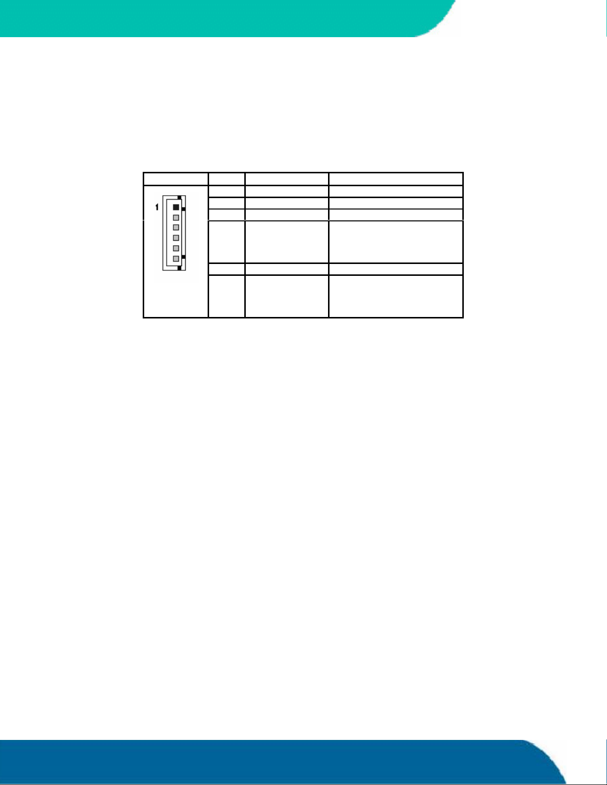
The sound connector is available through Connector X2 (6 pins). The following table shows the
pinout. To find the location of the connectors see the Appendix E: Connector Layout chapter.
Header Pin Signal Name Function
KONTRON
1 Right Line-level stereo output right.
2 ASGND Analog Ground
3 Left Line-level stereo output left.
4 AUXAR_C Auxiliary A input right. Normally
intended for connection to an
internal or external CD-ROM
analog output.
5 MIC_C Mono Microphone input.
6 AUXAL_C Auxiliary A input left. Normally
intended for connection to an
internal or external CD-ROM
analog output.
17.2 Configuration
From the BIOS Setup Utility in the I/O Device Configuration Submenu, you can set the onboard
legacy audio to Disabled (default) or Enabled. You can enable legacy Sound Blaster compatibility
mode or MPU-401 legacy MIDI support. Several configurations for I/O-addresses, interrupts and
DMA-channels are possible. Refer to the Appendix B: BIOS operation for more details
You can download available drivers for the sound controller from the Kontron Web site or use the
drivers provided by the manufacturer Realtek. Search for ALC650 drivers for the required operating
system.
17.3 Technical Support for Sound
If problems occur, you can solve some of them by using the latest drivers for the Sound controller.
Kontron provides you with the latest tested drivers, which can differ from newer ones. For further
technical support, contact either Kontron, or obtain support information and downloadable
software updates from Realtek.
Sound Interface 42 speedMOPSlcdCEUser’s Guide
Page 51
KONTRON
18. FAN INTERFACE
SomespeedMOPSlcdCEs can be equipped with a fan. If a fan has to be changed or added, use this
interface to connect a fan to cool the CPU. The connector and onboard system controller monitor
the fan’s speed. This connector supports 5V fans only.
18.1 Connector
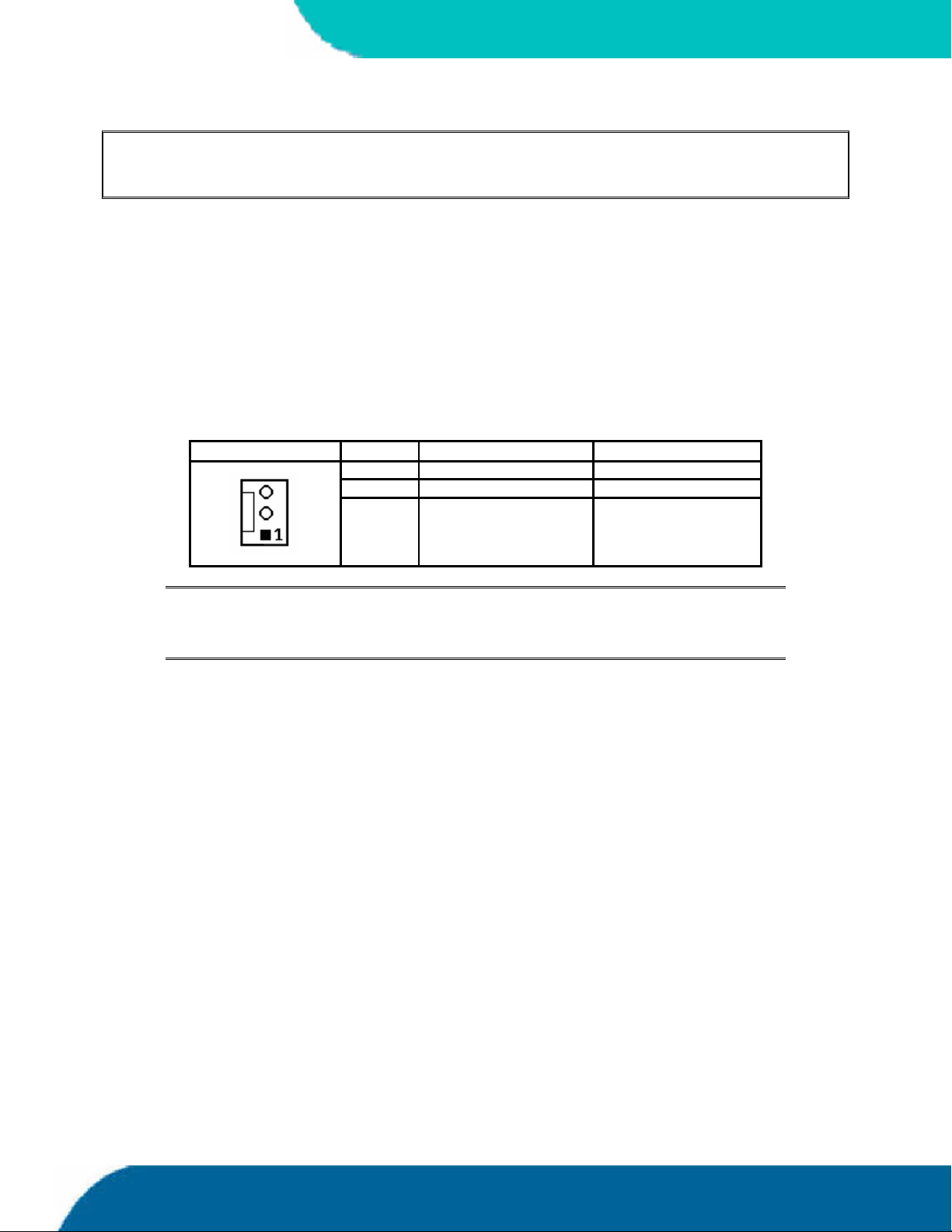
The fan interface is available on Connector X9 (3 pins). For the location of the fan connector see
Appendix E: Connector Layout.
Header Pin Signal Description Function
1 Sense Speed Monitoring
2 VCC * +5V
3 GND Ground
Notes: (*) To protect the external power lines of peripheral devices, make sure that:
-- the wires have the right diameter to withstand the maximum available current
-- the enclosure of the peripheral device fulfils the fire-protecting requirements of
-- IEC/EN 60950.
18.2 Configuration
You do not need to configure this feature.
speedMOPSlcdCEUser’s Guide 43 Fan Interface
Page 52
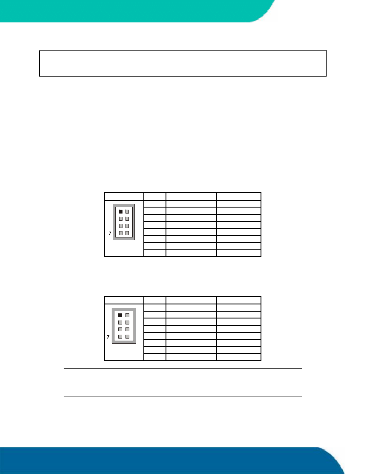
19. POWER INTERFACE
In some applications, the speedMOPSlcdCE is intended for use as a stand-alone module without a
backplane. You need to have a power connector available on the board for direct power supply. The
speedMOPSlcdCE is a +5V-only board. Peripherals can obtain additional voltage from the power
connectors next to the PC/104 bus. The additional voltages (+3.3V, +12V, -5V and -12V) are not
generated onboard the speedMOPSlcdCE.
Two connectors provide power to the speedMOPSlcdCE and it is strictly recommended that both
connectors are used. To find the location of the power connectors on the board, please see the
Appendix E: Connector Layout chapter.
19.1 Main Power Connector
The main power connector is available as J6A (8 pins). The following table shows the pinout.
KONTRON
Header Pin Signal Name Function
1 GND Ground
1
2 VCC +5V
3 BATT Battery
4 +12V +12V
5 -5V -5V
8
6 -12V -12V
7 GND Ground
8 VCC +5V
19.2 Auxiliary Power Connector
The auxiliary power connector is available as X5 (8 pins). The following table shows the pinout.
Header Pin Signal Name Function
1 GND Ground
1
2 VCC +5V
3 VCC +5V
4 GND Ground
5 GND Ground
8
6 VCC +5V
7 VCC +5V
8 GND Ground
Notes: (*) To protect the external power lines of peripheral devices, make sure that:
-- the wires have the right diameter to withstand the maximum available current
-- the enclosure of the peripheral device fulfils the fire-protecting requirements of
-- IEC/EN 60950.
Power Interface 44 speedMOPSlcdCE User’s Guide
Page 53
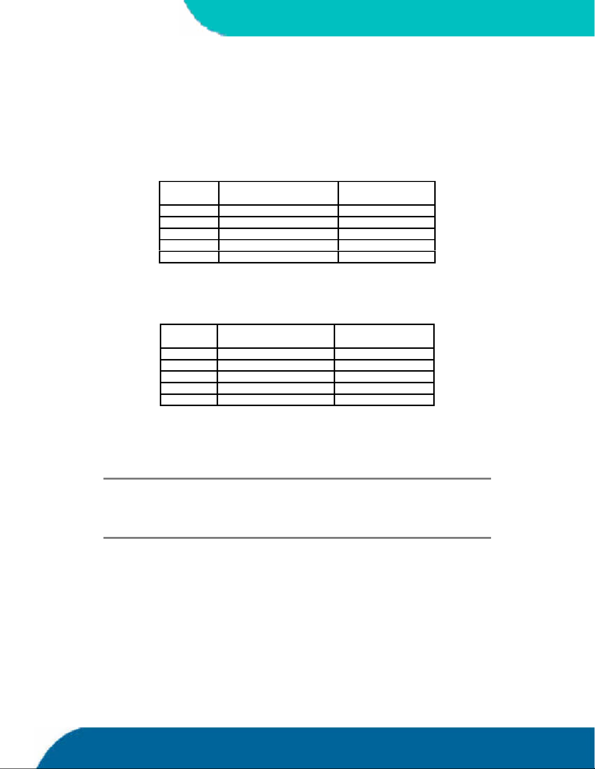
KONTRON
19.3 Power Pins
Every power pin on the two power connectors as well as on the PC/104 bus connectors is limited to
a maximum current of 1A per pin.
If a system using a speedMOPSlcdCE is only supplied from the two power connectors, the following
limitations apply:
Power Number of Pins on both
power connectors
VCC (+5V) 6 6A
+12V 1 1A
-12V 1 1A
-5V 1 1A
GND 6 6A
Max. Current
A system using the speedMOPSlcdCE also can be supplied from the PC/104 bus connectors. If only
those supply voltages pins are used, the following limitations apply:
Power Number of pins on ISA
part
VCC (+5V) 4 4A
+12V 2 2A
-12V 2 2A
-5V 2 2A
GND 8 8A
Max. Current
Modules on the PC/104 bus consuming a higher supply current must provide power supply through
an additional connector.
Note: The speedMOPSlcdCE is not a replacement for a backplane. Use all power pins
on the power connectors and on the PC/104 connectors for power supply to the
board, and also use all additional power connectors on additional I/O cards, if
your system exceeds the above limitations. It is not acceptable to use only the
power pins of the PC/104 connector for power supply of the full PC/104 stack.
19.4 Configuration
The speedMOPSlcdCE is equipped with a power management system (APM). You can configure lots
of options for power-saving states such as standby state with partial power reduction and suspend
state with full-power reduction. You can specify wake-up events that bring the system back to fullon state. Please refer to the “Power Menu” section in the “Appendix B: BIOS Operation” chapter.
speedMOPSlcdCEUser’s Guide 45 Power Interface
Page 54

19.5 External Battery
You can connect an external battery to Pin 3 (BATT) of the power connector instead of Pin 9 of the
keyboard connector. For more information refer to the Keyboard and Feature Interface section.
Note: The two battery inputs are protected against each other by diodes.
KONTRON
Power Interface 46 speedMOPSlcdCE User’s Guide
Page 55

KONTRON
20. WATCHDOG TIMER
The watchdog timer (WDT) is integrated in the Winbond W83627HF controller of the
speedMOPSlcdCEand can issue a reset to the system or generate a non-maskable interrupt (NMI).
The watchdog timer circuit has to be triggered within a specified time by the application software.
If the watchdog timeris not triggered because proper software execution fails or a hardware
malfunction occurs, it resets the system or generates the NMI.
20.1 Configuration
You can set the watchdog timer to disabled, reset or NMI mode. You can specify the delay time and
the timeout (trigger period) from 1 second to 30 minutes. The delay time is the time after first
initialization before the trigger period starts. The timeout is the time the watchdogtimer has to be
triggered within. You can make the initialization settings in the BIOS setup. Refer to the Watchdog
Settings Submenu in the Appendix B: BIOS Operation chapter for information on configuration.
20.2 Programming
20.2.1. Initializing the WDT
You can initialize the watchdog timer from the BIOS setup. You also can set up the initialization
from the application software with help of the JIDA (Jumptec Intelligent Device Architecture)
programmer’s interface.
20.2.2. Triggering the WDT
The watchdogtimer needs to be triggered out of the application software within a specified timeout
period. You can only do this in the application software with the help of the JIDA programmer’s
interface.
For information about the JIDA programmer’s interface, refer to the JIDA BIOS extension section in
the Appendix B: BIOS chapter and separate documents that are available in the JIDA software
packages on the Kontron Web site.
speedMOPSlcdCEUser’s Guide 47 Watchdog Timer
Page 56

21. HARDWARE MONITOR
The Winbond W83627HF controllermonitors several critical hardware parameters of the system,
including power-supply voltages, fan speed and CPU temperature, which are very important for a
high-end computer system to remain stable and function properly. This controller is connected via
the SM (System Management) bus to the south bridge.
The following parameters are monitored:
+3.3V from onboard DC/DC
CPU core voltage
+5V standby voltage
KONTRON
Battery voltage
CPU temperature with on-die diode
CPU fan speed (planed)
21.1 Configuration
You can use the Hardware Monitor submenu in the BIOS Setup Utility to obtain information on
voltages, fan speed and to check the temperature of the CPU die. For more information on this
submenu, see the Appendix B: BIOS Operation chapter in this manual.
To monitor the parameters of this feature from your operating system, Kontron recommends that
you use the 32-bit protected mode JUMPtec’s Intelligent Device Architecture driver (JIDA 32) with
the test and demo application forWindows 95/98/ME/NT/2000/XP, which is available on the
KONTRON Web site.
Hardware Monitor 48 speedMOPSlcdCEUser’s Guide
Page 57

KONTRON
22. THERMAL MANAGEMENT
The Thermal Managementfeature of the speedMOPSlcdCE helps control the processor’s temperature
by activating the automatic thermal throttling after the processor silicon reaches a certain
temperature. This feature can be enabled and configured in the BIOS Setup utility. You can specify
the temperature level when throttling starts, define a hysteresis value to get back to 100% CPU
performance, and specify the percentage for CPU performance in throttling mode. Automatic
thermal throttling mode does not require additional hardware, software drivers, or interrupt-
handling routines.
Additionally the processor of the speedMOPSlcdCE protects itself from catastrophic overheating by
using an internal thermal sensor. This sensor is set well above the normal operating temperature to
ensure that there are no false trips. The processor will stop all execution when the junction
temperature exceeds the sensor setting. This is signaled to the system by the THERMTRIP# (Thermal
Trip) pin. Once activated, the signal remains latched, and the processor stopped, until RESET# goes
active. There is no hysteresis built into the thermal sensor itself; as long as the die temperature
drops below the trip level, a RESET# pulse will reset the processor and execution will continue. If
the temperature has not dropped below the trip level, the processor will continue to drive
THERMTRIP# and remain stopped.The temperature level for catastrophic overheating being
activated is 135°C.
speedMOPSlcdCEUser’s Guide 49 Thermal Management
Page 58
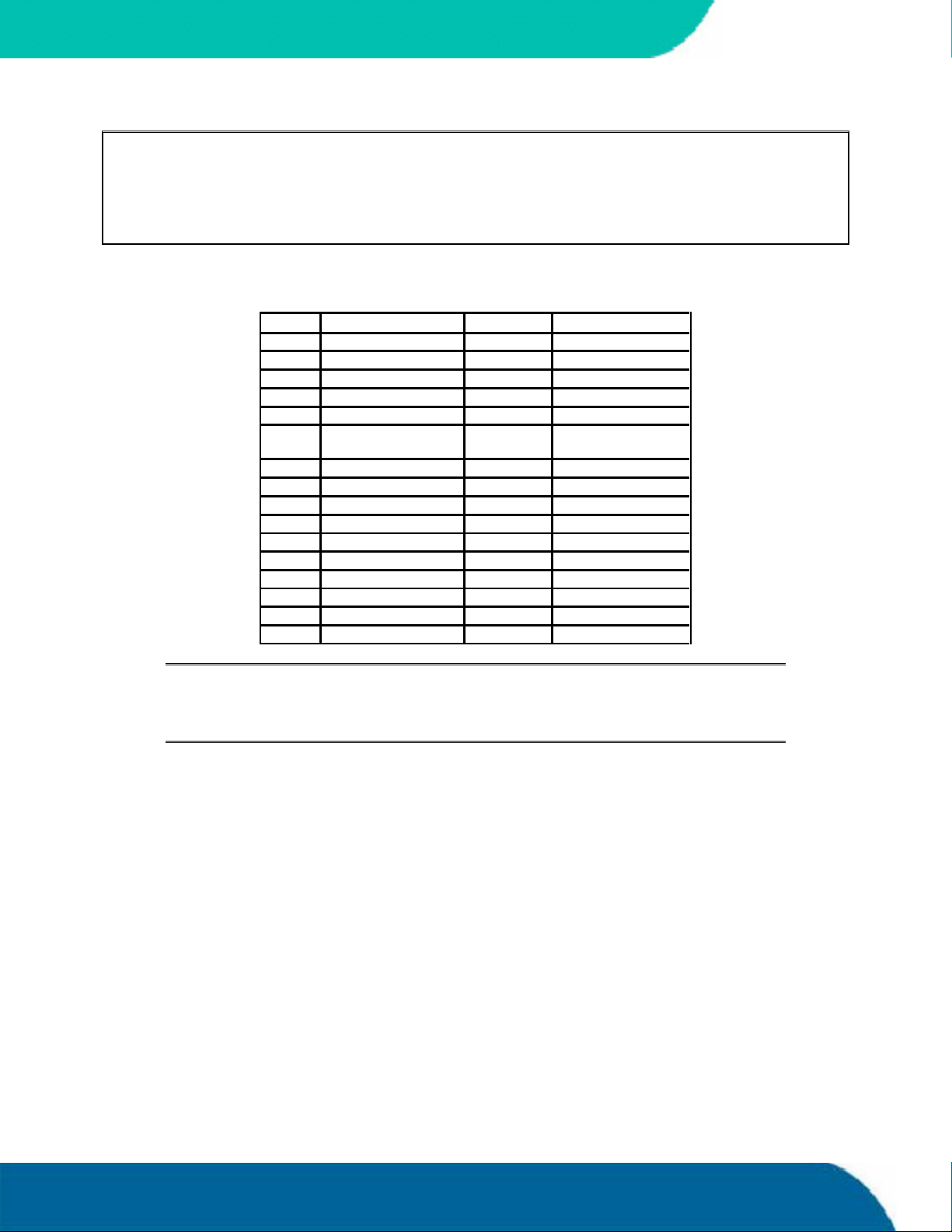
23. APPENDIX A: SYSTEM-RESOURCE
ALLOCATION
23.1 Interrupt Request (IRQ) Lines
IRQ # Use Available Comment
0 Timer0 No
1 Keyboard No
2 Slave 8259 No
3 COM2 No Note (1)
4 COM1 No Note (1)
5 Sound No Note (1), Note (2),
Note (3)
6 FDC No Note (1)
7 LPT1 No Note (1)
8 RTC No
9 Yes
10 Yes
11 Yes
12 PS/2 Mouse No Note (1)
13 FPU No
14 IDE0 No Note (1)
15 IDE11 No Note (1)
KONTRON
Notes: (1) If the „used for“-device is disabled in setup, the corresponding interrupt is
available for other devices.
(2) Possible setting for LPT1. IRQ7 is the default setting.
(3) Used in Soundblaster compatibility mode.
Appendix A: System Resource Allocations 50 speedMOPSlcdCE User’s Guide
Page 59
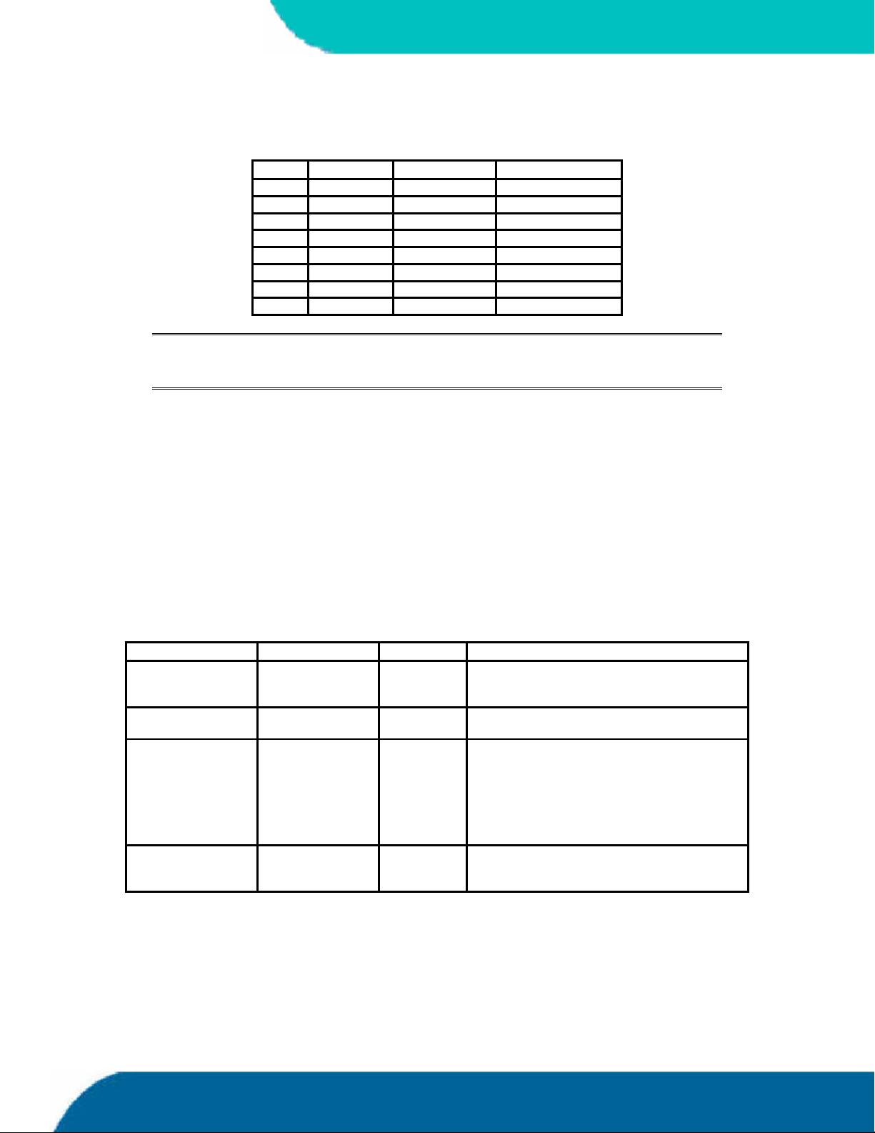
KONTRON
23.2 Direct Memory Access (DMA) Channels
DMA # Use Available Comment
0 Yes
1 Sound No Note (1), (2)
2 FDC No Note (1)
3 LPT Yes Note (2)
4 Cascade No
5 Yes
6 Yes
7 Yes
Notes: (1) If the „used for“-device is disabled in setup, the corresponding DMA
channel is available for other devices.
(2) Possible setting for LPT1 if configured for ECP mode.
23.3 Memory Map
The speedMOPSlcdCE processor modules can support up to 512MB of memory. The first 640KB of
SDRAM are used as main memory.
Using DOS, you can address 1MB of memory directly. Memory area above 1MB (high memory,
extended memory) is accessed under DOS via special drivers such as HIMEM.SYS and EMM386.EXE,
which are part of the operating system. Please refer to the operating system documentation or
special textbooks for information about HIMEM.SYS and EMM386.EXE.
Other operating systems (Linux or Windows) allow you to address the full memory area directly.
Upper Memory Use Available Comment
A0000h – BFFFFh VGA Memory No Mainly used by graphic adapter cards. If a PCI
graphic card is in the system this memory area
is mapped to the PCI bus.
C0000h – CFFFFh VGA BIOS,
RPL/PXE ROM
D0000h – DFFFFh Yes Free for ISA bus or shadow RAM in standard
E0000h – F0000h System BIOS,
USB legacy
support
No
configurations.
If JRC software is used, a 16K block is
shadowed for BIOS extension, starting with first
free area at D0000h, D4000h, D8000hor
DC000h. (BIOS extensions do not use the
whole shadow block.)
No
speedMOPSlcdCEUser’s Guide 51 Appendix A: System-Resource Allocation
Page 60

23.3.1. Using Expanded Memory Managers
speedMOPSlcdCEextension BIOSes can be mapped to an upper memory area. (See the previous
table.) Some add-on boards also have optional ROMs or use drivers that communicate with their
corresponding devices via memory mapped I/O such as dual-ported RAM. These boards have to
share the upper memory area with the Expanded Memory Manager’s EMS frame. This often causes
several problems in the system.
Most EMMs scan the upper memory area for extension BIOSes (optional ROMs) and choose a free
memory area for their frame if it is not explicitly set. Normally, they are not always capable of
detecting special memory-mapped I/O areas. You need to tell the EMM which memory areas are not
available for the EMS frames, which is most of the time done by using special exclusion parameters.
If the Expanded Memory Manager you use cannot detect extension BIOSes (optional ROMs), make
sure you excluded all areas in the upper memory, which are used by extension BIOSes, too. Your
instruction in the CONFIG.SYS concerning the Expanded Memory Manager should look like this:
(question marks for location of extension BIOS).
MS-DOS Example
DEVICE=EMM386.EXE X=????-???? X=E000-FFFF
KONTRON
Note: When booting up your system using this configuration under MS-DOS, the
exclusion of area F000 to FFFF causes a warning. Microsoft reports that this
message will always appear when the F000 segment lies in the shadow RAM.
This is a bug of EMM386, not the speedMOPSlcdCE.
Please read the technical manuals of add-on cards used with the speedMOPSlcdCE for the memory
areas they use. If necessary, also exclude their memory locations to avoid a conflict with EMM386.
Appendix A: System Resource Allocations 52 speedMOPSlcdCE User’s Guide
Page 61

KONTRON
23.4 I/O Address Map
The I/O-port addresses of the speedMOPSlcdCE are functionally identical with a standard PC/AT. All
addresses not mentioned in this table should be available. We recommend that you do not use I/O
addresses below 0110hex with additional hardware for compatibility reasons, even if available.
Address (h) Use Available Comment
0000 - 001F DMA Controller 1 No Fixed
0020 - 003D Interrupt Controller 1 No Fixed
002E - 002F LPC Super I/O No Fixed
0040 - 0053 Timer, Counter No Fixed
004E - 004F LPC Super I/O No Fixed
0060 - 0067 Keyboard controller No Fixed
0070 - 0077 Real Time Clock and
CMOS Registers
0080 - 008F DMA Page Register No Fixed
0090 - 009F DMA Control No Fixed
0092 Reset Generator No Fixed
00A0 00BF Interrupt Controller 2 N o Fixed
00C0 - 00DF DMA Controller 2 No Fixed
00E1 - 00E2 System Control No Fixed
00F0 Math. Coprocessor No Fixed
0100 - 010F General Purpose I/O No Kontron Control Port, Fixed
0170 - 0177 Hard Disk Drive
(Secondary)
01F0 - 01F7 Hard Disk Drive (Primary) No Available if IDE port 1 is disabled
0200 - 026F System Resources No Fixed
0274 - 0279 ISA PNP Data No Fixed
0278 - 027F LPT Yes Possible address for LPT
0290 - 0297 System Resources No Fixed
02F8 - 02FF COM2 No Available if COM is disabled
0376 IDE Controller 2 No Available if IDE port 2 is disabled
0378 - 037F LPT No Available if LPT is disabled
03B0 - 03DF Graphic Subsystem No Fixed
03F0 - 03F7 Floppy Controller No Available if floppy controller is disabled
03F6 IDE Controller 1 No Available if IDE port 1 is disabled
03F8 - 03FF COM1 No Available if COM is disabled
04D0 - 04D1 Interrupt Select No Fixed
0600 - 060F System Resources No Fixed
0678 - 067F ECP LPT Yes Used when LPT mode is set to ECP
0778 - 077F ECP LPT Yes Used when LPT mode is set to ECP
0A79 ISA PNP Data No Fixed
0CF8 - 0CFF PCI Configuration No Fixed
1000 - 107F System Resources No Fixed
1180 - 11BF System Resources No Fixed
1800 - 181F USB Host Controller No Dynamic (address if all PCI onboard devices are on)
1C00 - 1C0F Ultra ATA Storage
Controller
2000 - 201F SM-Bus Controller No Dynamic (address if all PCI onboard devic es are on)
2400 - 243F Sound No Dynamic (address if all PCI onboard devices are on)
2800 - 28FF Sound No Dynamic (address if all PCI onboard devices are on)
3000 - 30FF Ethernet Contr. DM9102 No Dynamic (address if all PCI onboard devices are on)
3400 - 343F Ethernet Contr. Intel No Dynamic (address if all PCI onboard devices are on)
No Fixed
No Available if IDE port 2 is disabled
No Dynamic (address if all PCI onboard devices are on)
speedMOPSlcdCEUser’s Guide 53 Appendix A: System-Resource Allocation
Page 62
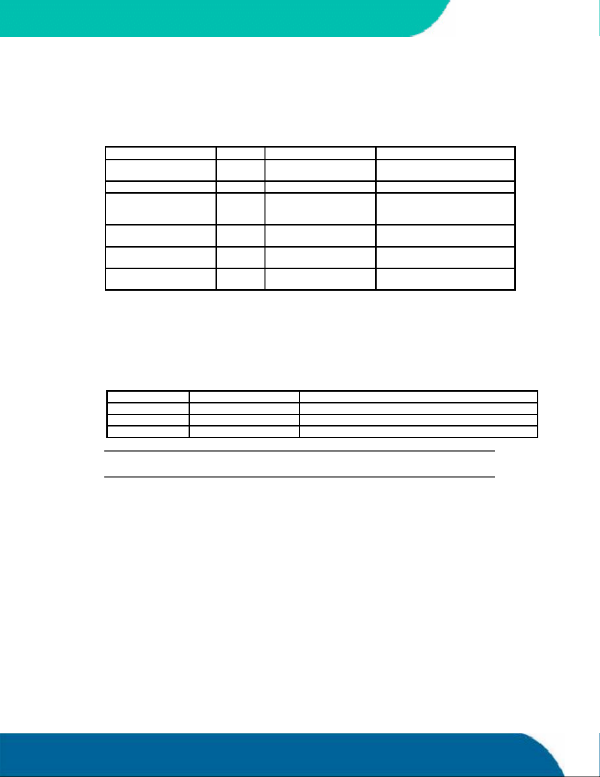
23.5 Peripheral Component Interconnect (PCI) Devices
All devices follow the PCI 2.1 specification. The BIOS and OS control memory and I/O resources.
Please refer to the PCI 2.1 specification for details.
PCI Device (IDSEL) PCI IRQ REQ/ GNT Comment
AGP Graphic - - Separate bus,
integrated in Intel chipset
Intel Ethernet (AD24) INTE# Discrete channel
Davicom Ethernet (AD17) INTD# REQ#3/GNT#3 PC/104-Plus allows 3 external
masters REQ#0, REQ#1 and
REQ#2
AC97 Sound INTB# Separate bus,
integrated in Intel chipset
1stUHCI USB Controller INTA# - Separate bus,
integrated in Intel chipset
EHCI USB Controller INTH# Separate bus,
integrated in Intel chipset
23.6 SM Bus Devices
KONTRON
The speedMOPSlcdCE uses an onboard SM (System Management) Bus. This bus is not available on an
external connector.
The following SM Bus addresses are already used on the speedMOPSlcdCE.
SM Bus Address SM Device Comment
10h/11h SM-Bus Host Integrated in Intel ICH4
A0h/A1h SPD EEPROM Part of the DDR SDRAM module
D2h/D3h Clock Generator
Note: Accesses to the onboard SM Bus devices that are not allowed may cause system
failures. Problems resulting from this are not under warranty!
Appendix A: System Resource Allocations 54 speedMOPSlcdCE User’s Guide
Page 63

KONTRON
24. APPENDIX B: BIOS OPERATION
The speedMOPSlcdCE comes with Phoenix BIOS 4.0, Release 6.1, which is located in the onboard
Flash EEPROM in compressed from. The device has an 8-bit access. The shadow RAM feature offers
faster access (16 bit). You can update the BIOS using a Flash utility. For complete Phoenix BIOS 4.0
information, visit the Phoenix Technologies Web site.
24.1 Determining the BIOS Version
To determine the BIOS version of the speedMOPSlcdCE, immediately press the <Pause/Break> key
on your keyboard as soon as you see the following text display in the upper left corner of your
screen:
PhoenixBIOS 4.0 Release 6.1
Copyright 1985-2003 Phoenix Technology Ltd.
All Rights Reserved
Kontron(R) BIOS Version <P815R112>
Copyright 2002-2004 Kontron Embedded Modules GmbH
Whenever you contact technical support about BIOS issues, providing a BIOS version <P815R???> is
especially helpful.
The system BIOS provides additional information about the board’s serial number, CPU, and
memory information by displaying information similar to the following:
S/N: MAA010102
CPU = Mobile Intel(R) Celeron(TM) CPU 733MHz
62M System RAM Passed
256K Cache SRAM Passed
System BIOS shadowed
Video BIOS shadowed
UMB upper limit segment address: E4EA
The board’s serial number has valuable information for technical support. The speedMOPSlcdCE
serial numbers always start with MA and are followed by a character and six digits. The firstthree
positions represent the lot number (here A01), and the last four digits are the number of the board
in that lot (here board number 102).
speedMOPSlcdCEUser’s Guide 55 Appendix B: BIOS Operation
Page 64
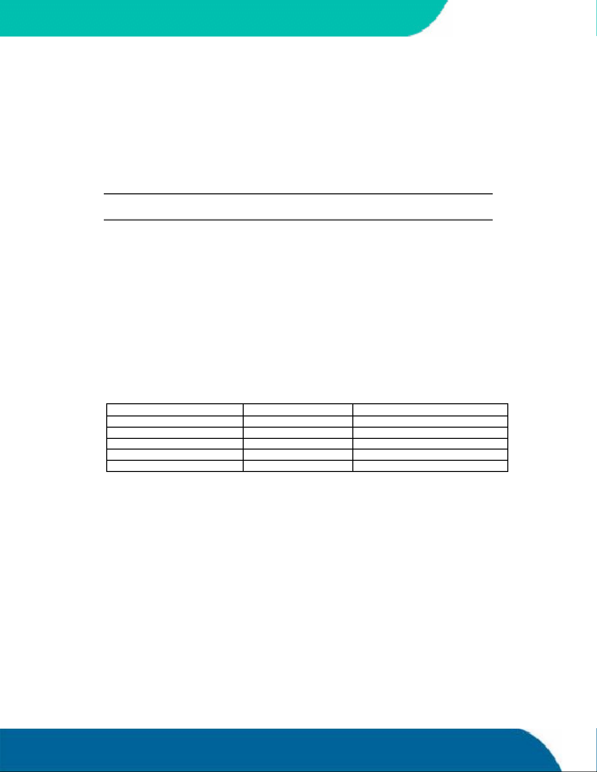
24.2 Configuring the System BIOS
The Phoenix BIOS setup utility allows you to change system behavior by modifying the BIOS
configuration. Setup-utility menus allow you to make changes and turn features on or off.
BIOS setup menus represent those found in most models of the speedMOPSlcdCE. The BIOS setup
utility for specific models can differ slightly.
Note: Selecting incorrect values can cause system boot failure. Load setup-default
values to recover by pressing <F9>.
24.2.1. Start Phoenix BIOS Setup Utility
To start the Phoenix BIOS Setup Utility, press the <F2> key when the following string appears
duringboot-up.
Press <F2> to enter Setup
KONTRON
The Main Menu then appears.
24.2.2. General Information
The Setup Screen is composed of several sections:
Setup Screen Location Function
Menu Bar Top Lists and selects all top-level menus.
Legend Bar Bottom Lists setup navigation keys.
Item Specific Help Window Right Help for selected item.
Menu Window Left Center Selection fields for current menu.
General Help Window Overlay (center) Help for selected menu.
Menu Bar
The menu bar at the top of the window lists different menus. Use the left/right arrow keys to make a
selection.
Appendix B:BIOS Operation 56 speedMOPSlcdCEUser’s Guide
Page 65
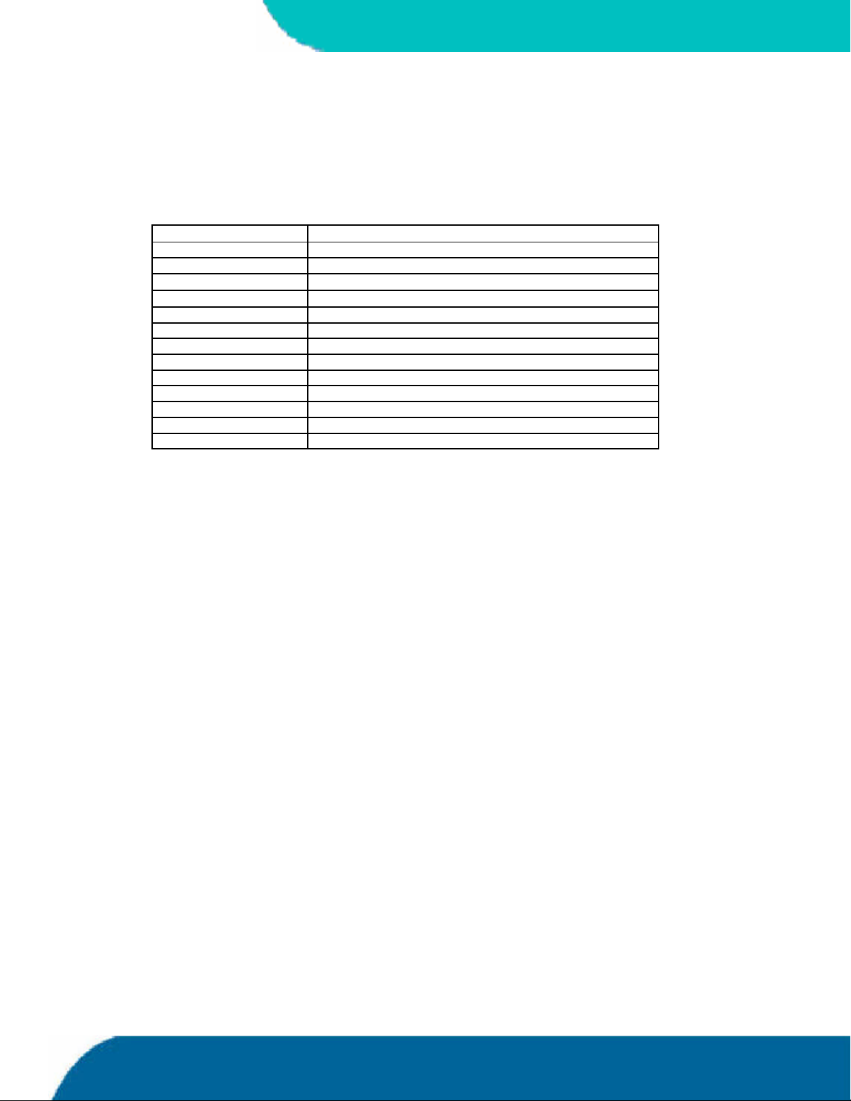
KONTRON
Legend Bar
Use the keys listed in the legend bar on the bottom to make your selections or exit the current
menu. The table below describes the legend keys and their alternates.
Key Function
<F1> or <Alt-H> General Help window.
<Esc> Exit menu.
or Arrow key Select a menu.
or Arrow key Select fields in current menu.
<Tab> or <Shift-Tab> Cycle cursor up and down.
<Home> or <End> Move cursor to top or bottom of current window.
<PgUp> or <PgDn> Move cursor to next or previous page.
<F5> or <-> Select previous value for the current field.
<F6> or <+> or <Space> Select next value for the current field.
<F9> Load the default configuration values for this menu.
<F10> Save and exit.
<Enter> Execute command or select submenu.
<Alt-R> Refresh screen.
Selecting an Item
Use theor key to move the cursor to the field you want. Then use the + and - keys to select a
value for that field. Save Value commands in the Exit menu save the values displayed in all menus.
Displaying Submenus
Use the or key to move the cursor to the submenu you want. Then press <Enter>. A pointer
() marks all submenus.
Item Specific Help Window
The Help window on the right side of each menu displays the Help text for the selected item. It
updates as you move the cursor to each field.
General Help Window
Pressing <F1> or <ALT-F1> on a menu brings up the General Help window that describes the
legend keys and their alternates. Press <Esc> to exit the General Help window.
speedMOPSlcdCEUser’s Guide 57 Appendix B: BIOS Operation
Page 66

24.3 Main Menu
Feature Option Description
System Time HH:MM:SS Sets system time.
System Date MM/DD/YYYY Sets system date.
Legacy Diskette A 360 Kb, 5 ¼ “
Legacy Diskette B 360 Kb, 5 ¼ “
Primary Master
Primary Slave
Secondary Master
Secondary Slave
Smart Device
Monitoring
System Memory N/A Displays amount of conventional
Extended Memory * N/A Displays amount of extended
Press <Enter> to move to MM or SS.
Press <Enter> to move to DD or
YYYY.
Select the type of floppy disk drive.
1.2 MB, 5 ¼ “
720 Kb, 3 ½ “
1.44/1.25 MB, 3 ½ “
2.88 MB, 3 ½ “
Disabled
Select the type of floppy disk drive.
1.2 MB, 5 ¼ “
720 Kb, 3 ½ “
1.44/1.25 MB, 3 ½ “
2.88 MB, 3 ½ “
Disabled
Autodetected drive Displays result of PM autotyping.
Autodetected drive Displays result of PS autotyping.
Autodetected drive Displays result of SM autotyping.
Autodetected drive Displays result of SS autotyping.
Disabled
Enabled
Turns on Self-Monitoring Analysis-
Reporting Technology, which
monitors the condition of the hard
drive and reports when a
catastrophic IDE failure is about to
happen.
memory detected during boot-up.
memory detected during boot-up.
KONTRON
Notes: In the Option column, bold shows default settings.
(*) Extended Memory = capacity of memory module – selected frame buffer
memory size (Video boot type)
Appendix B:BIOS Operation 58 speedMOPSlcdCEUser’s Guide
Page 67
KONTRON
24.3.1. Master or Slave Submenus
Feature Option Description
Type None
IDE Removable
ATAPI Removable
Cylinders 1 to 65,536 Number of cylinders.
Heads 1 to 256 Number of read/write heads.
Sectors 1 to 63 Number of sectors per track.
Maximum Capacity N/A Displays the calculated size of the drive in CHS.
Total Sectors N/A Number of total sectors in LBA mode.
Maximum Capacity N/A Displays the calculated size of the drive in LBA.
Multi-Sector Transfer Disabled
LBA Mode Control Disabled
32-Bit I/O Disabled
Transfer Mode Standard
FPIO 3 / DMA 1
FPIO 4 / DMA 2
Ultra DMA Mode * Disabled
SMART Monitoring Disabled
User
Auto
CD-ROM
Other ATAPI
2 sectors
4 sectors
8 sectors
16 sectors
Enabled
Enabled
Fast PIO 1
Fast PIO 2
Fast PIO 3
Fast PIO 4
MODE 0
MODE 1
MODE 2
Enabled
None = Autotyping is not able to supply the drive
type or end user has selected None, disabling any
drive that may be installed.
User = End user supplies HDD information.
Auto = Autotyping. The drive itself supplies the
information.
CD- ROM = CD-ROM drive.
ATAPI Removable = Read- and writeable media
e.g. LS120 and USB-ZIP
Other ATAPI = for ATAPI devices not supported by
other HDD features.
Any selection except Disabled determines the
number of sectors transferred per block.
The standard is one sector per block.
Enabling LBA causes Logical Block Addressing to
be used in place of CHS.
Enables 32-bit communication between CPU and
IDE card. Requires PCI or local bus.
Selects the method for transferring the data
between the hard disk and system memory.
Selects the UDMA mode to move data to/from the
drive. Autotype the drive to select the optimum
transfer mode. This feature is autodetected.
Shows whether a disk supports SMART.
Note: In the Option column, bold shows default settings.
(*) The board only supports up to UDMA33. This is a limitation from the
44pin IDE interfaces.
speedMOPSlcdCEUser’s Guide 59 Appendix B: BIOS Operation
Page 68
24.4 Advanced Menu
Feature Option Description
Advanced Chipset Control
PCI/PNP Configuration Sub menu Opens PCI/PNP Config sub menu.
Memory Cache
I/O Device Configuration Sub menu Opens Peripheral Config sub menu.
Keyboard Features Sub menu Opens Keyboard Features sub menu.
Hardware Monitor Sub menu Shows the current state of the hardware monitor.
Watchdog Settings Sub menu Opens Watchdog Config sub menu.
Display Control Sub menu Opens Display Control sub menu
Miscellaneous Sub menu Opens sub menu with miscellaneous options.
24.4.1. Advanced Chipset Control Submenu
Sub menu Opens Advanced Chipset Control sub menu.
Sub menu Opens Cache Control sub menu.
KONTRON
Feature Option Description
Video boot type Disabl e Onboard Video
Onboard Video 512K
Onboard Video 1MB
Enable Memory gap Disabled
Extended
Note: In the Option column, bold shows default settings.
Disable Onboard Graphics Device,
sets the legacy UMA video memory
to 512KByte or 1MB.
Allows enabling a 1MB memory gap
for add-on cards at 15MB.
Appendix B:BIOS Operation 60 speedMOPSlcdCEUser’s Guide
Page 69
KONTRON
24.4.2. PCI/PNP Configuration Submenu
Feature Option Description
PNP OS installed No
Reset Configuration Data * No
Secured Setup Configuration Yes
PCI Device, Slot #x
PCI IRQ line 1
PCI IRQ line 2
PCI IRQ line 3
PCI IRQ line 4
Onboard LAN IRQ line **
Onboard USB EHCI IRQ line **
PCI/PNP ISA IRQ Resource
Exclusion
Default Primary Video Adapter AGP
Sub menu Opens sub menu to configure slot x PCI
Disabled
Auto Select
IRQ3, 4, 5, 7, 9, 10,
11, 12, 14,15
Sub menu Opens IRQ Exclusion sub menu.
Yes
Yes
No
PCI
If your system has a PnP OS (such as
Win9x), select Yes to let the OS configure
PnP devices not required for booting. No
allows the BIOS to configure them.
Yes erases all configuration data in ESCD,
which stores the configuration settings for
plug-in devices. Select Yes when required to
restore the manufacturer’s defaults.
Yes prevents a Plug and Play OS from
changing system settings.
device.
Select IRQs for external PIC interrupts
A/B/C/D and the onboard Davicom LAN and
USB2.0 host controller.
Select Auto to let the BIOS assign the IRQ.
In a system with an AGP and a PCI video
adapter end user can select the adapter,
which will be initialized by the BIOS.
Notes: In the Option column, bold shows default settings.
(*) Setting this option to “yes”, under certain circumstances, may help
recovery from a system boot failure or a resource conflict.
(**) Not visible when corresponding device is disabled.
24.4.3. PCI Device, Slot #x Submenu
Feature Option Description
Option ROM Scan Disabled
Enabled
Enable Master Disabled
Enabled
Latency Timer Default, 20h, 40h, 60h, 80h, A0h,
C0h, E0h
Note: In the Option column, bold shows default settings.
Initialize device expansion ROM.
Enables device in slot as a PCI bus
master, not every device can function
as a master. Check device
documentation.
Minimum guaranteed time slice
allocated for bus master in units of PCI
bus clocks.
A high-priority, high-throughput device
may benefit from a greater value.
speedMOPSlcdCEUser’s Guide 61 Appendix B: BIOS Operation
Page 70

24.4.4. PCI/PNP ISA IRQ Resource Exclusion Submenu
Feature Option Description
IRQ3 Available
Reserved
IRQ4 Available
Reserved
IRQ5 Available
Reserved
IRQ7 Available
Reserved
IRQ9 * Available
Reserved
IRQ10 Available
Reserved
IRQ11 Available
Reserved
IRQ12 Available
Reserved
IRQ14 ** Available
Reserved
IRQ15 ** Available
Reserved
Reserves the specified IRQ for use
KONTRON
by legacy ISA devices.
See above.
See above.
See above.
See above.
See above.
See above.
See above.
See above.
See above.
Notes: In the Option column, bold shows default settings.
(*) IRQ9 is used for SCI in ACPI mode. Do not use IRQ9 for legacy ISA
devices when ACPI enabled.
(**) Entry is only visible when primary IDE or secondary IDE is disabled.
Appendix B:BIOS Operation 62 speedMOPSlcdCEUser’s Guide
Page 71

KONTRON
24.4.5. Memory Cache Submenu
Feature Option Description
Memory Cache Disabled
Cache System BIOS area Uncached
Cache Video BIOS area Uncached
Cache Extended Memory area Uncached
D000 - D3FF
D400 - D7FF
D800 - DBFF
DC00 - DFFF
Enabled
Write Protect
Write Protect
Write Through
Write Protected
Write Back
Disabled
Write Through
Write Protected
Write Back
Enables or Disables L2 cache.
Controls caching of System BIOS area.
Controls caching of Video BIOS area.
Controls caching of system memory
above 1MB.
Disabled: block is not cached.
Write Through: Write are cached and sent to
main memory at once.
Write Protect: Writes are ignored.
Write Back: Writes are cached but not sent to
main memory until necessary.
Note: In the Option column, bold shows default settings.
speedMOPSlcdCEUser’s Guide 63 Appendix B: BIOS Operation
Page 72
24.4.6. I/O Device Configuration Submenu
Feature Option Description
Local Bus IDE adapter Disabled
Primary
Secondary
Both
USB UHCI Host Controller 1 Enabled
Disabled
USB EHCI Host Controller ** Enabled
Disabled
Legacy USB Support *** Enabled
Disabled
AC97 Audio Controller Enabled
Disabled
Onboard LAN Controller 1 Disabled
Enabled
Onboard LAN PXE ROM Disabled
Enabled
Onboard LAN Controller 2
(planed)
Floppy disk controller Disabled
Serial port A, B Disabled
Serial port B, C * Disabled
Base I/O address 3F8h, 2F8h, 3E8h, 2E8h Select I/O base of port.
IRQ (port A and B) IRQ 3, IRQ 4 Select IRQ of Port A and B
IRQ (port C and D) * IRQ10, IRQ11 Select IRQ of Port C and D
Mode Normal,
Disabled
Enabled
Enabled
Enabled
Auto
Enabled
Auto
IR
KONTRON
Enables onboard PCI IDE device.
Enable / Disable UHCI 1 Host Controller
for USB ports 0 and 1.
Controls USB 2.0 functionality.
Enable support for USB keyboard and mice and
boot from USB mass storage devices.
Enable/Disable the AC97 Audio device.
Enables the ICH4 internal LAN controller.
Enables the remote boot BIOS extension for the
onboard LAN controller 1.
Enables the Davicom LAN controller.
Enable / Disable the onboard FDC controller.
Disabled turns off the port.
Enabled requires end user to enter the base I/O
address and the IRQ.
Auto makes the BIOS configure the port.
Disabled turns off the port.
Enabled requires end user to enter the base I/O
address and the IRQ.
Auto makes the BIOS configure the port.
Set the mode for Serial Port B.
Notes: In the Option column, bold shows default settings.
(*) Only visible if an external I/O controller (SMSC669) is on the OEM
backplane.
(**) The USB ports are multiplexed between UHCI and EHCI. Ports are
routed to EHCI if an USB 2.0 high-speed device is connected and an
EHCI driver is loaded.
(***) If you want to use the USB boot feature, enable USB BIOS Legacy
Support. A 16kb UMB area (most likely DC000h-DFFFFh) is used for
USB BIOS Legacy Support.
Appendix B:BIOS Operation 64 speedMOPSlcdCEUser’s Guide
Page 73
KONTRON
Parallel Port Disabled
Enabled
Auto
Mode Output only
Bi-directional
EPP
ECP
Base I/O address 378h, 278h Select I/O base of port.
IRQ IRQ 5, IRQ 7 Select IRQ of parallel port.
DMA DMA1, DMA3 Select DMA channel of port if in ECP mode.
Note: In the Option column, bold shows default settings.
24.4.7. Keyboard Features Submenu
Feature Option Description
Numlock Auto
On
Off
Key Click Disabled
Enabled
Keyboard auto- repeat rate 30/sec, 26.7/sec, 21.8/sec,
18,5/sec, 13.3/sec, 10/sec,
6/sec, 2/sec
Disabled turns off the port.
Enabled requires end user to enter the base I/O
address and the IRQ.
Auto makes the BIOS configure the port.
Set the mode for the parallel port.
On or Off turns NumLock
on or off at boot-up.
Auto turns NumLock on if it finds a
numeric key pad.
Turns audible key click on.
Sets the number of times to repeat a
keystroke per second if you hold the
key down.
Keyboard auto-repeat delay ¼ sec, ½ sec, ¾ sec, 1 sec Sets the delay time after the key is
held down before it begins to repeat
the keystroke.
Note: In the Option column, bold shows default settings.
24.4.8. Hardware Monitor Submenu
This submenu shows the current voltages, temperatures and the fan speed of the system.
Voltage/Temperature/Fan Explanation
VCC 3.3V Voltage 3.3V power plane
CPU Core Voltage CPU core voltage
5Vsb Voltage 5V-Standby voltage
Battery Voltage Battery voltage
CPU Temperature CPU Temperature in °C and °F
CPU Fan Speed
(not available until BIOS
revision P815R112)
”no function” will be displayed on boards with passive cooling
CPU fan speed in rpm,
speedMOPSlcdCEUser’s Guide 65 Appendix B: BIOS Operation
Page 74
24.4.9. Watchdog Timer Settings Submenu
Feature Option Description
Mode Disabled
Reset
NMI
Delay 1s, 5s, 10s, 30s, 1min, 5.5min,
10.5min, 30.5min
Timeout 1s, 5s, 10s, 30s, 1min, 5.5min,
10.5min, 30.5min
Note: In the Option column, bold shows default settings.
24.4.10. Display Control Submenu
KONTRON
Select watchdog-timer
operational mode.
The time until the watchdog timer
counter starts counting. Useful to
handle longer boot times.
Max. trigger period.
Feature Option Description
Display Mode CRT only
LCD only
CRT+LCD
JDA Revision x.x Displays the revision of the JILI data area image.
Flat Panel Type VGA *
SVGA *
XGA *
XGA2 *
SXGA *
Enter PAID
Enter FPID
Auto
PAID/FPID ** 0 – FFFF, default 0 Enter the JILI3 ID.
Flat Panel
Backlight ***
Flat Panel
Contrast ****
0 – 255, default
128
0 – 63, default 32 Enter a value to adjust contrast of the LCD.
Select Auto to let the BIOS automatically detect the panel
type or use one of the predefined fixed panel types.
Enter a value to adjust backlight of the LCD.
Select display mode.
Choose Enter PAID or Enter FPID
to manually set JILI3 ID values.
Note: In the Option column, bold shows default settings.
(*) Standard timings for VGA to SXGA panels cannot drive all available
displays of that type that are on the market. Use a JILI cable whenever
possible.
(**) Only visible if Enter PAID or Enter FPID are selected.
(***) Only visible if the panel adapter is equipped with a MAX5362 DAC for
backlight control.
(****) Only visible if the panel adapter is equipped with a Xicore X9429 digital
potentiometer for contrast control.
Appendix B:BIOS Operation 66 speedMOPSlcdCEUser’s Guide
Page 75

KONTRON
24.4.11. Miscellaneous Submenu
Feature Option Description
Floppy Check Disabled
Enabled
Summary Screen Disabled
Enabled
QuickBoot Mode Disabled
Enabled
Extended Memory
Testing
Dark Boot Disabled
Halt On Errors Yes
PS/2 Mouse Auto Detect
Large Disk Access
Mode
Normal *
Just zero it
None
Enabled
No
Enabled
Disabled
DOS
Other
Enabled verifies floppy type on boot; disabled speeds boot.
If enabled, a summary screen is displayed just before booting
the OS to let the end user see the system configuration.
Allows the system to skip certain tests while booting.
This decreases the time needed to boot the system.
Determines which type of tests will be performed
on memory above 1MB.
If enabled, system comes up with a blank screen instead of
the diagnostic screen during boot-up.
Determines if post errors cause the system to halt.
Selecting Disabled prevents any installed PS/2 mouse from
functioning but frees up IRQ12. Selecting Autodetect frees
IRQ12 if no mouse is detected.
Select DOS if you have DOS. Select Other if you have
another OS such as UNIX.
A large disk is one that has more than 1024 cylinders, more
than 16 heads or more than 63 sectors per track.
Note: In the Option column, bold shows default settings.
(*) The option normal is not visible when QuickBoot is enabled.
Dark Boot
After you turn on or reset the computer, Dark Boot displays a graphical logo (default is a blank
screen) instead of the text based POST screen, which displays a number of PC diagnostic messages.
The graphical logo stays up until just before the OS loads unless:
You press <Esc> to display the POST screen
You press <F2> to enter Setup
POST issues an error message
The BIOS or an option ROM requests keyboard input
speedMOPSlcdCEUser’s Guide 67 Appendix B: BIOS Operation
Page 76

24.5 Security Menu
Feature Option Description
Supervisor Password is Clear
User Password is Clear
Set User Password * Up to seven alphanumeric
Set Supervisor
Password *
Diskette access User
Fixed disk boot sector Normal
Virus check reminder Disabled
System backup
reminder
Password on boot Disabled
Set
Set
characters
Up to seven alphanumeric
characters
Supervisor
Write protected
Daily
Weekly
Monthly
Disabled
Daily
Weekly
Monthly
Enabled
KONTRON
Displays whether password is set.
Displays whether password is set.
Pressing <Enter> displays the dialog
box for entering the user password.
In related systems, this password
gives restricted access to setup.
Pressing <Enter> displays the dialog
box for entering the user password.
In related systems, this password
gives full access to setup.
Enabled requires supervisor
password to access floppy disk.
Write protect the boot sector on the
hard disk for virus protection.
Requires a password to format or
Fdisk the hard disk.
Displays a message during boot-up
asking (Y/N) if you backed up the
system or scanned for viruses.
Message returns on each boot until
you respond with Y.
Daily displays the message on the
first boot of the day, Weekly on the
first boot after Sunday, and monthly
on the first boot of the month.
Displays a message during boot-up
asking (Y/N) if you backed up the
system or scanned for viruses.
Message returns on each boot until
you respond with Y.
Daily displays the message on the
first boot of the day, Weekly on the
first boot after Sunday, and monthly
on the first boot of the month.
Enabled requires a password on
boot. Requires prior setting of the
supervisor password.
If supervisor password is set and this
option is disabled, BIOS assumes
user is booting.
Notes: In the Option column, bold shows default settings.
(*) Enabling Supervisor Password requires a password for entering Setup.
Passwords are not case sensitive.
User and Supervisor passwords are related. A User password is possible
only if a Supervisor password exists.
Appendix B:BIOS Operation 68 speedMOPSlcdCEUser’s Guide
Page 77

KONTRON
24.6 Power Menu
In the BIOS Setup Utility, you can set up an Advance Power Management system (APM 1.2) to
reduce the amount of energy used after specified periods of inactivity. The setup menu supports:
Full On State
Standby State with Partial Power Reduction
Suspend State with Full Power Reduction
Feature Option Description
Thermal Management * Sub menu Opens Thermal Management
Power Savings Disabled
Hard Disk Timeout Disabled, 10 sec – 15 min Inactivity period of hard disk required
Video Timeout Disabled, 10 sec – 15 min Inactivity period of user input device
Resume on Modem Ring Off
Resume on Time Off
Resume Time 00:00:00 Specifies time when system wakes.
Power Button Function Power Off
Power Loss Control Stay Off
Customized
Maximum Power Savings
Maximum Performance
On
On
Sleep
Power On
Last State
sub menu.
Maximum options select
predefined values.
Select Customized to make
selections from the following fields.
Disabled turns off
power management.
before standby (motor off).
before the screen is turned off.
Enabled wakes system on incoming
calls detected by mode (RI).
Enabled wakes the system
at a specific time.
Determines if the system enters
suspend or soft off when the power
button is pressed.
Determines how the system behaves
after a power failure. This only works
in conjunction with a CMOS backup
battery.
Notes: In the Option column, bold indicates default setting.
(*) See the chapter “Thermal Management” of this user’s guide
for more details about these features.
speedMOPSlcdCEUser’s Guide 69 Appendix B: BIOS Operation
Page 78
24.6.1. Thermal Management Submenu
Feature Option Description
Auto Thermal Throttling * Enabled
Disabled
Temperature 100°C
75 °C – 110 °C
Hysteresis 3°C, 4°C, 5 °C, 6°C When a level of Temperature – Hysteresis is
CPU Performance 13%, 25%, 50%, 75% Specifies the throttling percentage
Notes: In the Option column, bold indicates default setting.
(*) See the chapter “Thermal Management” of this user’s guide
for more details about these features.
KONTRON
Enables/Disables the automatic thermal throttling
of the processor’s clock. If disabled, the other
entries are not visible.
Sets the temperature level at which
throttling starts.
reached, the throttling stops and 100% CPU
performance is available again.
of the CPU performance.
Appendix B:BIOS Operation 70 speedMOPSlcdCEUser’s Guide
Page 79

KONTRON
24.7 Boot Menu and Utilities
MultiBoot is a boot utility integrated in the PhoenixBIOS 4.0. The speedMOPSlcdCE provides the
MultiBoot XP version with integrated Boot First function.
24.7.1. MultiBoot XP
MultiBoot XP comes with a complete new look of the Boot Device Priority submenu. This submenu is
now separated into two sections:
Boot Priority Order
Excluded from Boot Order
It can display the setup menus by each kind of device type and arrange the boot priority order with
any sequence of devices. MultiBoot XP meets the requirements of PC 98 and accommodates more
devices that are bootable. It employs a boot scheme that is generic and flexible enough to boot
from any current device. You can select your boot device in Setup, or you can choose a different
device each time you boot by selecting your boot device in the Boot First function.
An available bootable device can be easily switched between the two sections by just highlighting
the device and then pressing <X>. To change the order, select the device to change and press <-> to
decrease or <+> to increase priority. Youalso can choose between four default configurations for
the boot order <1>-<4>.
Boot Priority Order
This section shows eight configuration entries for up to eight devices that can be arranged in boot
priority order (1: highest priority, 8: lowest priority).
Excluded from Boot Order
This section shows all devices that are excluded from the boot order. Any device listed here will
never be used as boot device and not appear in the Boot First function.
speedMOPSlcdCEUser’s Guide 71 Appendix B: BIOS Operation
Page 80
The following table shows a list of supported devices:
Device Description
IDE 0 Primary master IDE hard drive
IDE 1 Primary slave IDE hard drive
IDE 2 Secondary master IDE hard drive
IDE 3 Secondary slave IDE hard drive
IDE CD IDE compatible CD-ROM drive
Legacy Floppy Drives Standard Legacy Diskette Drive
USB KEY USB stick
USB FDC USB Diskette Drive
USB HDD USB Hard Drive and memory sticks that follow MMS specification
USB CDROM USB CD-ROM Drive
USB ZIP USB ZIP Drive
USB LS120 USB LS120 Drive
PCI BEV Ethernet Controller on the PCI Bus with LAN Boot ROM
PCI SCSI SCSI Controller on the PCI Bus with SCSI BIOS ROM
24.7.2. Boot First Function
Display the Boot First function by pressing <Esc> during POST. In response, the BIOS displays the
message Entering Boot Menu and then displays the Boot Menu at the end of POST. With the
MultiBoot XP feature only devices detected during boot-up are displayed.
KONTRON
Use the menu to select a following option:
Override the existing boot sequence (forthis boot only) by selecting another boot
device. If the specified device does not load the OS, the BIOS reverts to the previous
boot sequence.
Enter Setup.
Press <Esc> to continue with the existing boot sequence.
Appendix B:BIOS Operation 72 speedMOPSlcdCEUser’s Guide
Page 81

KONTRON
24.8 Exit Menu
The following sections describe the five options in Exit Menu. Pressing <Esc> does not exit this
menu. You must select an item from the menu to exit.
Feature Option Description
Exit Saving Changes Saves selections and exits setup.
Exit Discarding
Changes
Load Setup Defaults Displays default values for all the
Discard Changes If, during a Setup session, you
Save Changes Saves all the selection without
The next time the system boots,
the BIOS configures the system
according to the Setup selection
stored in CMOS.
Exits Setup without storing in
CMOS any new selections you
may have made. The selections
previously in effect remain in
effect.
Setup menus.
change your mind about changes
you have made and have not yet
saved the values to CMOS, you
can restore the values you saved
to CMOS.
exiting Setup. You can return to
the other menus to review and
change your selection.
Exit saving changes.
Exit discarding changes.
Load setup defaults.
Discard changes.
Save changes.
speedMOPSlcdCEUser’s Guide 73 Appendix B: BIOS Operation
Page 82

24.9 Kontron BIOS Extensions
Besides the Phoenix System BIOS, thespeedMOPSlcdCE comes with a few BIOS extensions that
support special features. All extensions are located in the onboard Flash EEPROM. Some extensions
are permanently available; some areloaded if required during boot-up. Supported features include:
JIDA standard
Remote Control feature (JRC)
Onboard LAN RPL ROM
All enabled BIOS extensions require shadow RAM, which is loaded into the same 32K shadowed
memory block, if possible. However, if the system memory cannot find free memory space because
all the memory is already used for add-on peripherals, the BIOS extensions do not load.
24.9.1. JIDA BIOS extension
The JUMPtec Intelligent Device Architecture (JIDA) BIOS extension is not a true extension BIOS. It
is part of the system BIOS and is located in the system BIOS segments after boot-up. It is
permanently available and supports the JIDA 16-bit and JIDA 32-bit standard.
KONTRON
The JIDA 16-bit standard is a software interrupt 15hex driven programmers interface and offers lots
of board information functions. For detailed informationabout programming, refer to the JIDA
specification and a source code example (JIDAI???.ZIP), which you can find at the Kontron Web
site. The three question marks represent the revision number of the file. You also can contact
technical support for this file.
For other operating systems, special 32-bit drivers (JIDAIA??.ZIP) are available. You can download
the zip file from the Kontron Web site.
24.9.2. Remote Control Client Extension
You can remotely control the speedMOPSlcdCE using software available from Kontron (JRC-1, Part
Number 96047-0000-00-0). This software tool can communicate with the board via one of the serial
ports. During boot-up, the system BIOS scans the serial ports for an available JRC connection. If
detected, it loads the JRC client BIOS extension into the memory. With the JRC client loaded into
the first detected free memory location between C0000hex and DFFFFhex, a 16K block is shadowed.
For more information on the Remote Control usage, refer to the JRC-1 technical manual or
Application Note JRCUsage_E???.PDF, which you can find on the Kontron Web site.
Appendix B:BIOS Operation 74 speedMOPSlcdCEUser’s Guide
Page 83

KONTRON
24.9.3. LAN PXE ROM
If the onboard LAN PXE ROM is enabled in the system BIOS setup, a special optional ROM for the
Ethernet controller loads into memory during boot-up. This optional ROM allows you to boot the
speedMOPSlcdCEover an Ethernet connection. A server with Intel PXE boot support is required on
the other side of the Ethernet connection. The setup and configuration of the server, including PXE
support, is not the responsibility of Kontron.
The PXE ROM extension is loaded into the first free memory area between C0000hex and DFFFFhex
and a 16K block of memory is shadowed.
speedMOPSlcdCEUser’s Guide 75 Appendix B: BIOS Operation
Page 84
24.10 Updating or Restoring BIOS Using PhoenixPhlash
PhoenixPhlash allows you to update the BIOS by using a floppy disk without havingto install a new
ROM chip. PhoenixPhlash is a utility used to flash a BIOS to the Flash ROM installed on the
speedMOPSlcdCE.
Use PhoenixPhlash to:
Update the current BIOS with a newer version
Restore a corrupt BIOS
24.10.1. Flashing a BIOS
Use the following procedure to update or restore the BIOS.
1. Download the Phoenix Phlash compressed file, CRDxP815.ZIP, from the KONTRON
Embedded Modules Web site or contact your local technical support for it. The zip
file contains the following:
KONTRON
File Purpose
MAKEBOOT.EXE Creates the custom boot sector on the Crisis Recovery Diskette.
CRISBOOT.BIN Serves as the Crisis Recovery boot sector code.
MINIDOS.SYS Allows the system to boot in Crisis Recovery Mode.
PHLASH16.EXE Programs the flash ROM.
WINCRIS.EXE Creates the Crisis Recovery Diskette from Windows.
WINCRIS.HLP Serves as the help file of WINCRISES.EXE.
CRISDISK.BAT Batch file for crisis disk.
BIOS.WPH Serves as the actual BIOS image to be programmed into Flash ROM.
2. Install Phoenix Phlash on a hard disk by unzipping the contents of the
CRDxP815.ZIP into a local directory such as C:\PHLASH.
3. Create a Crisis Recovery Diskette by inserting a blank diskette into Drive A: or B:
and execute WINCRISIS.EXE. This copies three files onto the diskette.
File Purpose
MINIDOS.SYS Allows the system to boot in Crisis Recovery Mode.
PHLASH16.EXE Programs the flash ROM.
BIOS.ROM Serves as the actual BIOS image to be programmed into Flash ROM.
Appendix B:BIOS Operation 76 speedMOPSlcdCEUser’s Guide
Page 85

KONTRON
4. If the BIOS image (BIOS.ROM) changes because of an update or bug fix, copy the
new BIOS onto the diskette and name it BIOS.ROM.
Phoenix Phlash runs in either command line mode or crisis recovery mode.
5. Use the command line mode to update or replace the BIOS. To execute Phlash in
this mode, move to the Crisis Recovery Disk and type:
PHLASH16 <bios name> (Example: PHLASH16 P815R112.WPH)
PhoenixPhlash will update the BIOS. PhoenixPhlash can fail if the system uses
memory managers. If this occurs, the utility displays the following message:
Cannot flash when memory manager are present.
If you see this message after you execute Phlash, disable the memory manager or
use parameter /x for Phlash16.exe.
PHLASH16 /X <bios name>
24.10.2. Preventing Problems When Updating or Restoring BIOS
Updating the BIOS represents a potential hazard. Power failures or fluctuations can occur when you
update the Flash ROM can damage the BIOS code, making the system unbootable.
To prevent this hazard, many systems come with a boot-block Flash ROM. The boot-block region
contains a fail-safe recovery routine. If the boot-block code finds a corrupted BIOS (checksum
fails), it boots into the crisis recovery mode and loads a BIOS image from a crisis diskette (see
above).
Additionally, the end user can insert an update key into the parallel port (LPT) to force initiating
the boot block recovery routine.
For further information on the update key and the crisis diskette, see the Application Note
PHLASH_SCE???, which is available from the KONTRON Embedded Modules Web site. The three
question marks stand for the revision number of the file.
speedMOPSlcdCEUser’s Guide 77 Appendix B: BIOS Operation
Page 86
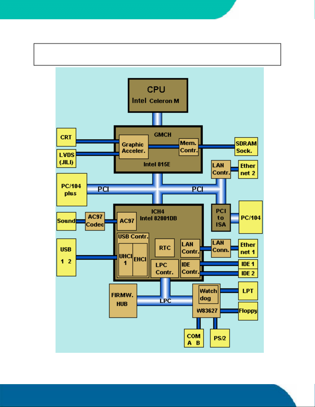
25. APPENDIX C: BLOCK DIAGRAM
KONTRON
Appendix C: Block Diagram 78 speedMOPSlcdCEUser’s Guide
Page 87
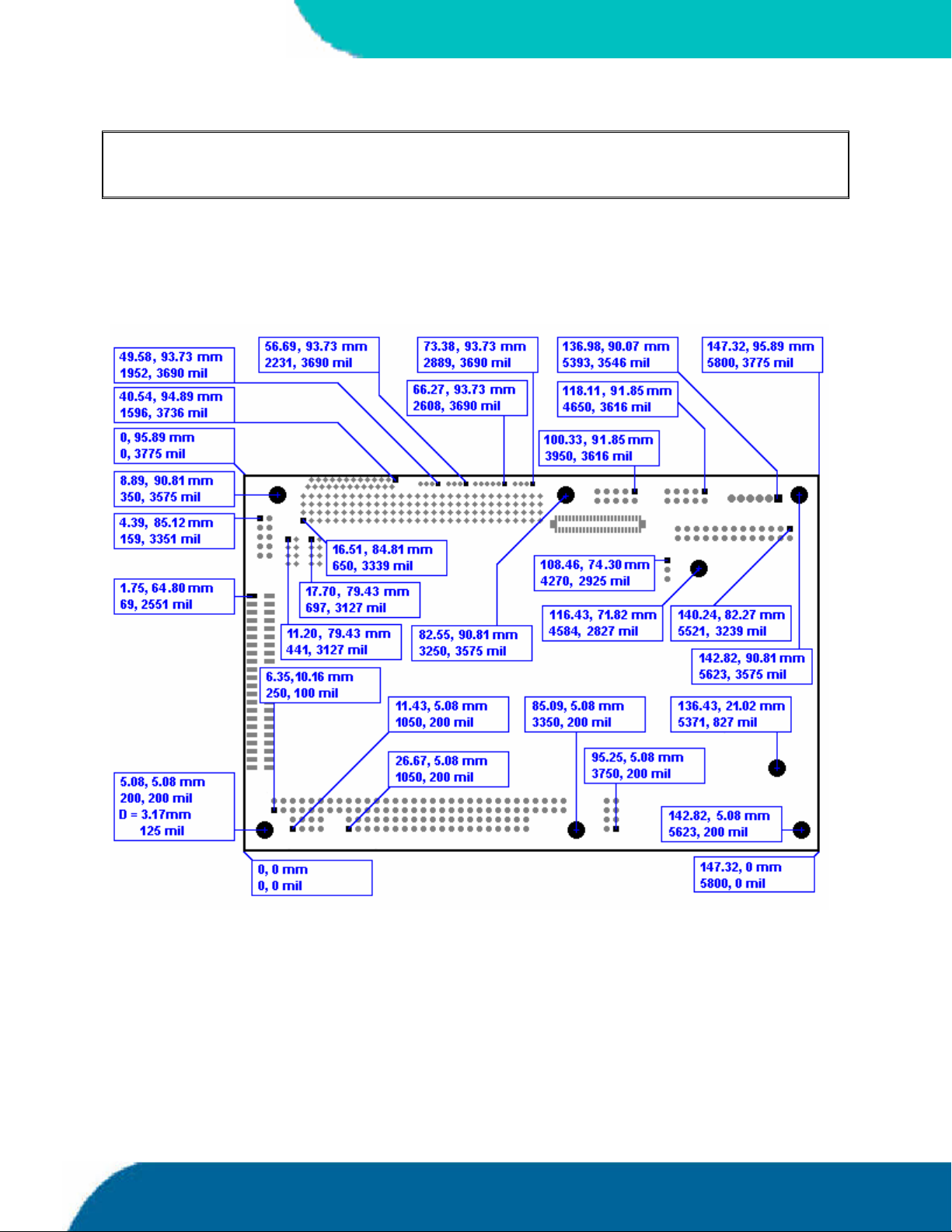
KONTRON
26. APPENDIX D: MECHANICAL DIMENSIONS
26.1 Board Dimensions and Mounting Holes
26.1.1. Top View
speedMOPSlcdCEUser’s Guide 79 Appendix D: Mechanical Dimensions
Page 88
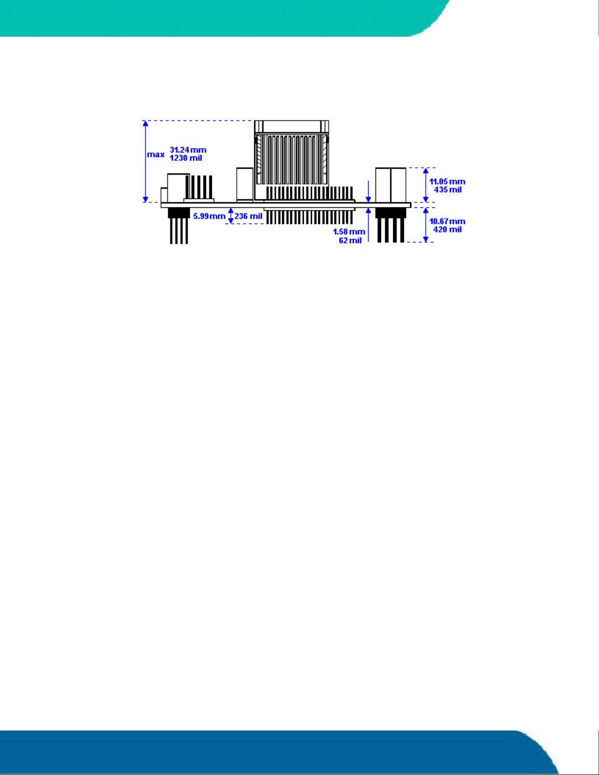
26.1.2. Side View
KONTRON
Appendix D: Mechanical Dimensions 80 speedMOPSlcdCEUser’s Guide
Page 89
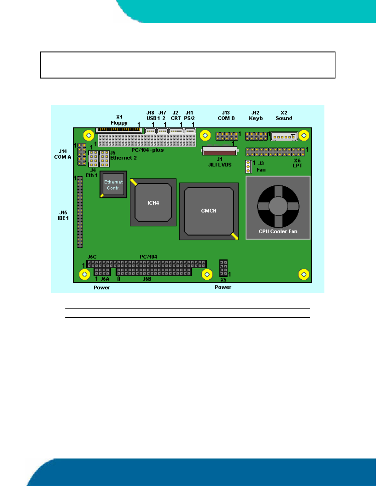
KONTRON
27. APPENDIX E: CONNECTOR LAYOUT
27.1 Top Side
Notes: The position of Pin 1 is marked with a quadratic pad on the PCB.
speedMOPSlcdCE User’s Guide 81 Appendix E: Connector Layout
Page 90
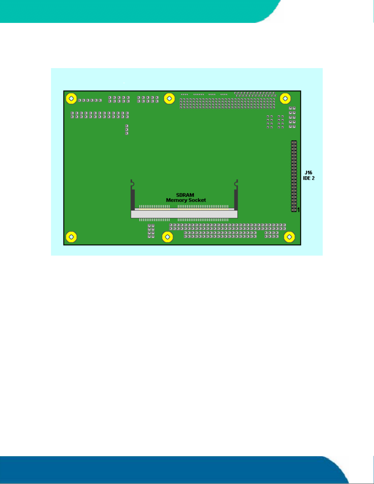
27.2 Bottom Side
KONTRON
Appendix E: Connector Layout 82 speedMOPSlcdCEUser’s Guide
Page 91

KONTRON
27.3 Connector Functions and Interface Cables
The table notes connector functions, as well as mating connectors and available cables.
Connector Function Mating Connector Available Cable Cable
Description
J1 Flat -panel display
J2 CRT Monitor
J3 Fan Connector 1.25mm 3 pos.
J4, J5 Ethernet Interface
J6A, X5 Power Connector 2.54mm 10 pos.
J6B PC/104 Bus
J6C PC/104 Bus
J8 PC/104-Plus Bus
J11 PS/2 Mouse
J12 Keyboard and Feature
J13, J14 Serial Interfaces COM
J15, J16 IDE Hard Disk
J17, J18 USB interface
X1 Floppy Drive
X2 Sound Connector 2.54mm 6 pos.
Connector
Connector
Connectors
(AT-bus part)
(XT-bus part)
(PCI part)
Connector
Connector
A and COM B
Connectors
Connector
Connectors
Connector
(Molex 51021-0600 or
(Molex 51021-0300 or
(Berg 90311-008 or compatible)
(AMP 1-215882-0 or
(EPT 962-60203-12 or
compatible for board to board
(EPT 962-60323-12 or
compatible for board to board
(EPT 264-60303-12)
(Molex 51021-0400 or
(AMP 1-215882-0 or
(AMP 1-215882-0 or
(Berg 89361-144 or compatible)
(Molex 51021-0400 or
with crimp contacts
JST SXH-001T-PO.6
JST SXH-002T-PO.6)
- KAB-JILI-????? Kontron JILI
1.25mm 6 pos.
compatible)
compatible)
2mm 8 pos.
compatible)
2.54mm 40 pos.
connection)
2.54mm 64 pos.
connection)
2mm 120pos.
1.25mm 4 pos.
compatible)
2.54mm 10 pos.
compatible)
2.54mm 10 pos.
compatible)
2mm 44 pos.
1.25mm 4 pos.
compatible)
(JST XHP-6
Or
KAB-VGA-2
(PN 96053-0000-00-0)
KAB-MOPS -ETN1
(PN 96048-0000-00-0)
KAB-MOUSE-PS2
(PN 96062-0000-00-0)
KAB-KB-1
(PN 96023-0000-00-0)
or
KAB-KB -PS2
(PN 96060-0000-00-0)
KAB-DSUB9-2
(PN 96017-0000-00-0)
KAB-IDE-25
(PN 96020-0000-00-0)
or
KAB-IDE-2MM
(PN 96021-0000-00-0)
KAB-USB-1
(PN 96054-0000-00-0)
ADA-FLOPPY-2
(PN 96001-0000-00-0)
or
KAB-FLOPPY/MOPS-1
(PN 96019-0000-00-0)
KAB-SOUND-CMP
(PN96063-0000-00-0)
cables.
For DSUB 15
adaptation.
For RJ45
adaptation.
For PS/2 mouse.
For AT-keyboard
PS/2 keyboard.
For DSUB 9
adaptation.
For 3.5” HDD
2.5” HDD.
For standard
USB adaptation.
For 3.5” floppy
slim-line floppy.
Cable with open
or
Or
or
ends
X6 LPT Connector 2.54mm 26 pos.
(AMP 2-215882-6 or
compatible)
KAB-DSUB25-1
(PN 96015-0000-00-0)
For DSUB 25
adaptation.
speedMOPSlcdCE User’s Guide 83 Appendix E: Connector Layout
Page 92
27.4 Pin-out Table
KONTRON
Pin
0 GND GND
1 /IOCHCK GND /SBHE /MEMCS16
2 SD7 RESETDRV LA23 /IOCS16
3 SD6 VCC (***) LA22 IRQ10
4 SD5 IRQ9 LA21 IRQ11
5 SD4 -5V LA20 IRQ12
6 SD3 DRQ2 LA19 IRQ15
7 SD2 -12V LA18 IRQ14
8 SD1 /0WS LA17 /DACK0
9 SD0 +12V /MEMR DRQ0
10 IOCHRDY GND (*) /MEMW /DACK5
11 AEN /SMEMW SD8 DRQ5
12 SA19 /SMEMR SD9 /DACK6
13 SA18 /IOW SD10 DRQ6
14 SA17 /IOR SD11 /DACK7
15 SA16 /DACK3 SD12 DRQ7
16 SA15 DRQ3 SD13 VCC (***)
17 SA14 /DACK1 SD14 /MASTER
18 SA13 DRQ1 SD15 GND
19 SA12 /REFRESH GND GND
20 SA11 SYSCLK
21 SA10 IRQ7
22 SA9 IRQ6
23 SA8 IRQ5
24 SA7 IRQ4
25 SA6 IRQ3
26 SA5 /DACK2
27 SA4 T/C
28 SA3 BALE
29 SA2 VCC (***)
30 SA1 OSC
31 SA0 GND
32 GND GND
J6C
Bus (A)
PC104-XT
J6C
Bus (B)
PC104-XT
J6B
Bus (C)
PC104-AT
J6B
Bus (D)
PC104-AT
Notes: (*) Key pin for PC/104; GND for PC/104+ specification
(***) To protect the external power lines of peripheral devices, make sure that:
- the wires have the right diameter to withstand the maximum available current
- the enclosure of the peripheral device fulfils the fire protecting requirements of
- IEC/EN 60950.
Appendix E: Connector Layout 84 speedMOPSlcdCEUser’s Guide
Page 93
KONTRON
Pin
1 GND Reserved VCC (***) AD00
2 VCC (***) AD02 AD01 AD03
3 AD05 GND AD04 AD03
4 C/BE0 AD07 GND AD06
5 GND AD09 AD08 GND
6 AD11 VCC (***) AD10 GND
7 AD14 AD13 GND AD12
8 VCC3 (**) C/BE1 AD15 VCC3 (**)
9 SERR GND SB0 PAR
10 GND PERR VCC3 (**) SDONE
11 STOP VCC3 (**) LOCK GND
12 VCC3 (**) TRDY GND DEVSEL
13 FRAME GND IRDY VCC3 (**)
14 GND AD16 VCC3 (**) C/BE2
15 AD18 VCC3 (**) AD17 GND
16 AD21 AD20 GND AD19
17 VCC3(**) AD23 AD22 VCC3 (**)
18 IS0 (AD20) GND IS1 (AD21) IS2 (AD22)
19 AD24 C/BE3 VI/O IS3 (AD23)
20 GND AD26 AD25 GND
21 AD29 VCC (***) AD28 AD27
22 VCC (***) AD30 GND AD31
23 REQ0 GND REQ1 VI/O
24 GND REQ2 VCC (***) GNT0
25 GNT1 VI/O GNT2 GND
26 VCC (***) CLK0 GND CLK1
27 CLK2 VCC (***) CLK3 GND
28 GND INTD VCC (***) RST
29 +12V INTA INTB INTC
30 -12V Reserved Reserved Reserved
J8
PC104+
Bus (A)
J8
PC104+
Bus (B)
J8
PC104+
Bus (C)
J8
PC104+
Bus (D)
Notes: (**) Not generated onboard of the speedMOPSlcdCE
(***) To protect the external power lines of peripheral devices, make sure that:
- the wires have the right diameter to withstand the maximum available current
- the enclosure of the peripheral device fulfils the fire protecting requirements of
- IEC/EN 60950.
speedMOPSlcdCE User’s Guide 85 Appendix E: Connector Layout
Page 94
KONTRON
Pin
IDE
J15
J16
X1
Floppy
1 /RESET VCC (***) /STB GND Right /DCD1 /DCD2
2 GND /IDX /AFD VCC (***) ASGND /DSR1 /DSR2
3 HDD7 VCC (***) PD0 BATT Left RXD1 RXD2
4 HDD8 /DR0 /ERR +12V (***) AUXAR_C /RTS1 /RTS2
5 HDD6 VCC (***) PD1 -5V (***) MIC_C TXD1 TXD2
6 HDD9 /DSKCHG /INIT -12V (***) AUXAL_C /CTS1 /CTS2
7 HDD5 NC PD2 GND /DTR1 /DTR2
8 HDD10 NC /SLIN VCC (***) /RI1 /RI2
9 HDD4 NC PD3 GND GND
10 HDD11 /MTR0 GND VCC (***) VCC (***)
11 HDD3 NC PD4
12 HDD12 /FDIR GND
13 HDD2 NC PD5
14 HDD13 /STEP GND
15 HDD1 GND PD6
16 HDD14 /W DATA GND
17 HDD0 GND PD7
18 HDD15 /W GATE GND
19 GND GND /ACK
20 KEY (NC) /TRK0 GND
21 DRQ GND BUSY
22 GND /WRTPRT GND
23 /IOW GND PE
24 GND /RDATA GND
25 /IOR GND SLCT
26 GND /HDSEL VCC (***)
27 IOCHRDY
28 CSEL
29 /AKJ
30 GND
31 SIRQ
32 NC
33 SA1
34 NC
35 SA0
36 SA2
37 /CS1
38 /CS3
39 NC
40 GND
41 VCC (***)
42 VCC (***)
43 GND
44 NC
X6
LPT
J6A
Power
X2
Sound
J14
COM A
J13
COM B
Notes: (***) To protect the external power lines of peripheral devices, make sure that:
- the wires have the right diameter to withstand the maximum available current
- the enclosure of the peripheral device fulfils the fire protecting requirements of
- IEC/EN 60950.
Appendix E: Connector Layout 86 speedMOPSlcdCEUser’s Guide
Page 95
KONTRON
Notes: (***) To protect the external power lines of peripheral devices, make sure that:
J4
Pin
1 SPEAKER TXD+ RED MSDAT VCC (***) GND Sense
2 GND TXD- GRN VCC (***) USB0 VCC (***) VCC (***)
3 /RESIN RXD+ BLU GND USB1 VCC (***) GND
4 /KBLOCK SHLDGND GND MSCLK GND GND
5 KBDAT SHLDGND VSYNC GND
6 KBCLK RXD- HSYNC VCC (***)
7 GND SHLDGND VCC (***)
8 VCC (***) SHLDGND GND
9 BATT
10 PWRGOOD
J12
KBD
- the wires have the right diameter to withstand the maximum available current
- the enclosure of the peripheral device fulfils the fire protecting requirements of
- IEC/EN 60950.
J5
Eth 1
J2
CRT
J11
PS/2
Mouse
J17
J18
USB
X5
Aux.
Power
J3
Fan
speedMOPSlcdCE User’s Guide 87 Appendix E: Connector Layout
Page 96

28. APPENDIX F: PC ARCHITECTURE
INFORMATION
The following sources of information can help you better understand PC architecture.
28.1 Buses
28.1.1. ISA, Standard PS/2 - Connectors
AT Bus Design: Eight and Sixteen-Bit ISA, E-ISA and EISA Design, Edward Solari,
Annabooks, 1990, ISBN 0-929392-08-6
AT IBM Technical Reference Vol 1&2, 1985
KONTRON
ISA & EISA Theory and Operation, Edward Solari, Annabooks, 1992, ISBN 0929392159
ISA Bus Specifications and Application Notes, Jan. 30, 1990, Intel
ISA System Architecture, Third Edition, TomShanley and Don Anderson, Addison-
Wesley Publishing Company, 1995, ISBN 0-201-40996-8
Personal Computer Bus Standard P996, Draft D2.00, Jan. 18, 1990, IEEE Inc
Technical Reference Guide, Extended Industry Standard Architecture Expansion Bus,
Compaq 1989
28.1.2. PC/104, PCI
Embedded PC 104 Consortium
The consortium provides information about PC/104 and PC/104-Plus technology. You
can search for information about the consortium on the Web.
PCI SIG
The PCI-SIG provides a forum for its ~900 member companies, who develop PCI
products based on the specifications that are created by the PCI-SIG. You can search for
information about the SIG on the Web.
PCI & PCI-X Hardware and Software Architecture & Design, Fifth Edition, Edward Solari
and George Willse, Annabooks, 2001,ISBN 0-929392-63-9.
PCI System Architecture, Tom Shanley and Don Anderson, Addison-Wesley, 2000, ISBN
0-201-30974-2.
Appendix F: PC Architecture Information 88 speedMOPSlcdCEUser’s Guide
Page 97

KONTRON
28.2 General PC Architecture
Embedded PCs, Markt&Technik GmbH, ISBN 3-8272-5314-4 (German)
Hardware Bible, Winn L. Rosch, SAMS, 1997, 0-672-30954-8
Interfacing to the IBM Personal Computer, Second Edition, Lewis C. Eggebrecht, SAMS,
1990, ISBN 0-672-22722-3
The Indispensable PC Hardware Book, Hans-Peter Messmer, Addison-Wesley, 1994,
ISBN 0-201-62424-9
The PC Handbook: For Engineers, Programmers, and Other Serious PC Users, John P.
Choisser and John O. Foster, Annabooks, 1997, ISBN 0-929392-36-1
28.3 Ports
28.3.1. RS-232 Serial
EIA-232-E standard
The EIA-232-E standard specifies the interface between (for example) a modem and a
computer so that they can exchange data. The computer can then send data to the
modem, which then sends the data over a telephone line. The data that the modem
receives from the telephone line can then be sent to the computer. You can search for
information about the standard on the Web.
RS-232 Made Easy: Connecting Computers, Printers, Terminals, and Modems, Martin D.
Seyer, Prentice Hall, 1991, ISBN 0-13-749854-3
National Semiconductor
The Interface Data Book includes application notes. Type “232” as a search criteria to
obtain a list ofapplication notes. You can search for information about the data book
on National Semiconductor’s Web site.
speedMOPSlcdCEUser’s Guide 89 Appendix F: PC Architecture Information
Page 98

28.3.2. ATA
28.3.3. USB
KONTRON
AT Attachment (ATA) Working Group
This X3T10 standard defines an integrated bus interface between disk drives and
host processors. It providesa common point of attachment for systems
manufacturers and the system. You can search for information about the working
group on the Web.
We recommend you also search the Web for information on 4.2 I/O cable, if you use
hard disks in a DMA3 or PIO4 mode.
USB Specification
USB Implementers Forum, Inc. is a non-profit corporation founded by the group of
companies that developed the Universal Serial Bus specification. The USB-IF was
formed to provide a support organization and forum for the advancement and
adoption of Universal Serial Bus technology. You can search for information about
the standard on the Web.
28.4 Programming
C Programmer’s Guide to Serial Communications, Second Edition, Joe Campbell, SAMS,
1987, ISBN 0-672-22584-0
Programmer's Guide to theEGA, VGA, and Super VGA Cards, Third Edition, Richard
Ferraro, Addison-Wesley, 1990, ISBN 0-201-57025-4
The Programmer’s PC Sourcebook, Second Edition, Thom Hogan, Microsoft Press, 1991,
ISBN 1-55615-321-X
Undocumented PC, A Programmer’s Guide to I/O, CPUs, and Fixed Memory Areas, Frank
van Gilluwe, Second Edition, Addison-Wesley, 1997, ISBN 0-201-47950-8
Appendix F: PC Architecture Information 90 speedMOPSlcdCEUser’s Guide
Page 99
KONTRON
29. APPENDIX G: DOCUMENT REVISION HISTORY
Version Date Edited by Changes
P815M101 06.10.2004 KFR Created preliminary manual
P815M110 01.04.2005 KFR First release
P815M111 13.09.2005 BHO/JL Updated support addresses, completed
specifications, updated drawings and tables, added
2ndEthernet information, updated BIOS chapter,
added measurements in mm
P815M112 22.11.2005 BHO Added power consumption values, added MTBF
value, new Kontron logo, Minor changes
SpeedMOPSlcdCEUser’s Guide 91 Appendix G: Document Revision History
 Loading...