

Page 1
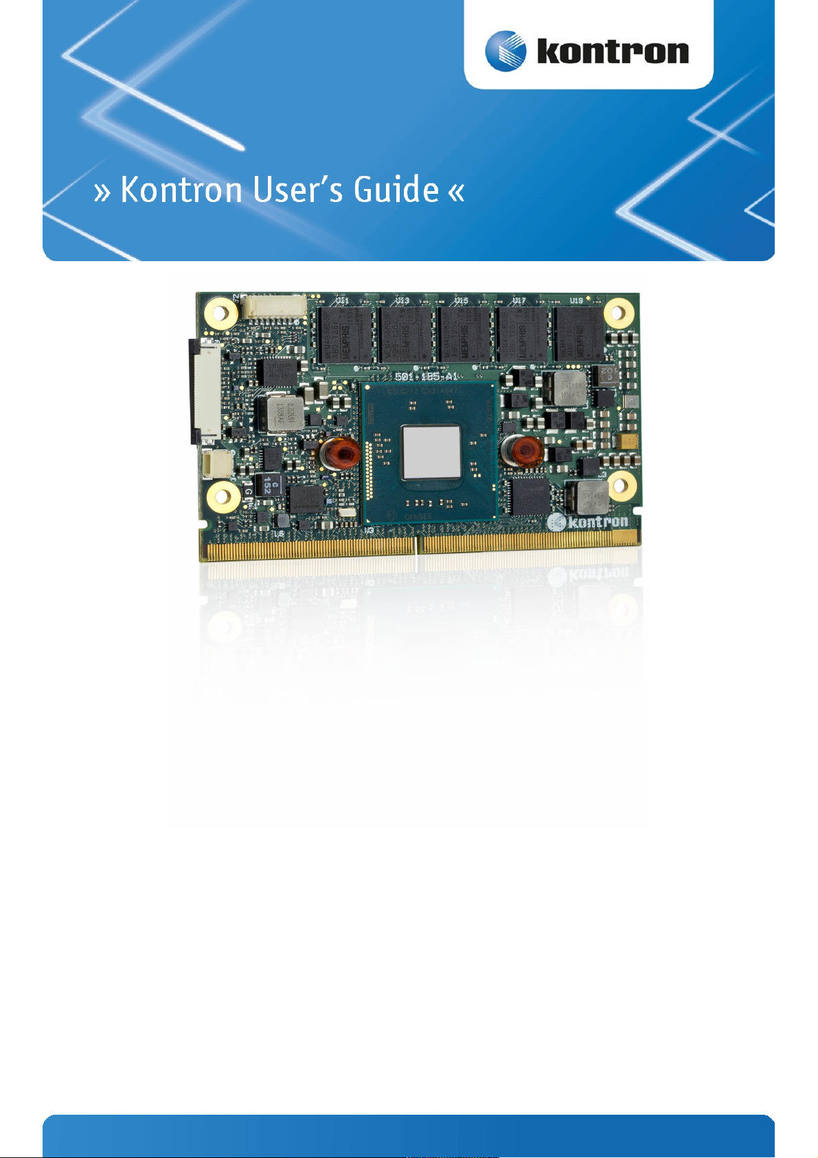
SMARC-sXBTi
Document Revision 0.1 preliminary
www.kontron.com
Page 2

Page 3

» Table of Contents «
1 User Information..................................................................................5
1.1 About This Document.................................................................................................................... 5
1.2 Copyright Notice.......................................................................................................................... 5
1.3 Trademarks................................................................................................................................. 5
1.4 Standards................................................................................................................................... 5
1.5 Warranty.................................................................................................................................... 6
1.6 Technical Support......................................................................................................................... 6
2 Introduction........................................................................................7
2.1 Product Description...................................................................................................................... 7
2.2 SMARC™ Computer-on-Modules....................................................................................................... 7
3 Product Specification............................................................................8
3.1 Modules & Accessories................................................................................................................... 8
3.2 Functional Specification............................................................................................................... 10
3.3 Block Diagram............................................................................................................................ 14
3.4 Electrical Specification................................................................................................................15
3.4.1 Supply Voltage........................................................................................................................... 15
3.4.2 Power Supply Rise Time................................................................................................................ 15
3.4.3 Supply Voltage Ripple.................................................................................................................. 15
3.4.4 Power Consumption..................................................................................................................... 15
3.5 Power Control............................................................................................................................ 16
3.6 Environmental Specification......................................................................................................... 17
3.6.1 Temperature Specification............................................................................................................ 17
3.6.2 Humidity................................................................................................................................... 17
3.7 Standards and Certifications.........................................................................................................18
3.8 MTBF........................................................................................................................................ 19
3.9 Mechanical Specification.............................................................................................................. 20
3.9.1 Module Dimension...................................................................................................................... 20
3.9.2 Height on Top............................................................................................................................ 20
3.9.3 Height on Bottom....................................................................................................................... 20
3.9.4 Mechanical Drawing.................................................................................................................... 20
3.10 Module Dimensions..................................................................................................................... 21
3.11 Thermal Management, Heatspreader and Cooling Solutions.................................................................22
4 Features and Interfaces.......................................................................23
4.1 Onboard eMMC Flash.................................................................................................................... 23
4.2 Secure Digital Card...................................................................................................................... 23
4.3 S5 Eco Mode.............................................................................................................................. 24
4.4 Speedstep Technology................................................................................................................. 25
4.5 C-States.................................................................................................................................... 26
4.6 Graphics Features....................................................................................................................... 27
4.7 ACPI Suspend Modes and Resume Events..........................................................................................28
www.kontron.com
Page 4

SMARC-sXBTi /
5 Connectors........................................................................................29
5.1 SMARC™ Connector Top Side.......................................................................................................... 29
5.2 SMARC™ Connector Bottom Side..................................................................................................... 31
6 BIOS Operation...................................................................................35
6.1 Determining the BIOS Version....................................................................................................... 35
6.2 BIOS Update.............................................................................................................................. 35
6.3 POST Codes................................................................................................................................ 35
6.4 Setup Guide............................................................................................................................... 35
4
Page 5

SMARC-sXBTi / User Information
1 User Information
1.1 About This Document
This document provides information about products from Kontron Europe GmbH and/or its subsidiaries. No warranty of
suitability, purpose, or fitness is implied. While every attempt has been made to ensure that the information in this
document is accurate, the information contained within is supplied “as-is” and is subject to change without notice.
For the circuits, descriptions and tables indicated, Kontron assumes no responsibility as far as patents or other rights of
third parties are concerned.
1.2 Copyright Notice
Copyright © 2003-2014 Kontron Europe GmbH
All rights reserved. No part of this document may be reproduced, transmitted, transcribed, stored in a retrieval system, or
translated into any language or computer language, in any form or by any means (electronic, mechanical, photocopying,
recording, or otherwise), without the express written permission of Kontron Europe GmbH.
DIMM-PC®, PISA®, ETX®, ETXexpress®, microETXexpress®, X-board®, DIMM-IO® and DIMM-BUS® are trademarks or
registered trademarks of Kontron Europe GmbH. Kontron is trademark or registered trademark of Kontron AG.
1.3 Trademarks
The following lists the trademarks of components used in this board.
» IBM, XT, AT, PS/2 and Personal System/2 are trademarks of International Business Machines Corp.
» Microsoft is a registered trademark of Microsoft Corp.
» Intel is a registered trademark of Intel Corp.
» All other products and trademarks mentioned in this manual are trademarks of their respective owners.
1.4 Standards
Kontron Europe GmbH is certified to ISO 9000 standards.
5
Page 6

SMARC-sXBTi / User Information
1.5 Warranty
For this Kontron Europe GmbH product warranty for defects in material and workmanship exists as long as the warranty
period, beginning with the date of shipment, lasts. During the warranty period, Kontron Europe GmbH will decide on its
discretion if defective products are to be repaired or replaced.
Within the warranty period, the repair of products is free of charge as long as warranty conditions are observed.
Warranty does not apply for defects arising/resulting from improper or inadequate maintenance or handling by the buyer,
unauthorized modification or misuse, as well as the operation outside of the product´s environmental specifications and
improper installation and maintenance.
Kontron Europe GmbH will not be responsible for any defects or damages to other products not supplied by Kontron
Europe GmbH that are caused by a faulty Kontron Europe GmbH product.
1.6 Technical Support
Technicians and engineers from Kontron Europe GmbH and/or its subsidiaries are available for technical support. We are
committed to make our product easy to use and will help you use our products in your systems.
Please consult our Website at http://www.kontron.com/support for the latest product documentation, utilities, drivers
and support contacts. Consult our customer section http://emdcustomersection.kontron.com for the latest BIOS
downloads, Product Change Notifications, Board Support Packages, DemoImages, 3D drawings and additional tools and
software. In any case you can always contact your board supplier for technical support.
6
Page 7

SMARC-sXBTi / Introduction
2 Introduction
2.1 Product Description
The new Kontron SMARC-sXBTi Computer-on-Modules has been developed to comply with the SMARC specification and is
equipped with Intel® Atom™ processor E3800 series and up to 8 GB RAM, optional with ECC. They support the extended
temperature range of -40°C to +85°C, measure only 82mm x 50mm and have an especially low-profile design thanks to
the use of edge card connectors. Nevertheless, there is still enough space for up a 64GB on-board SSD to store OS and
application data. A highlight of the pin-out is the mobile feature set with 3 UARTs with complete function range also for,
e.g., GPS as well as support of the MIPI-compliant serial camera interface (MIPI CSI = Mobile Industry Processor Interface
Camera Serial Interface). The powerful Intel® Gen 7 Graphics are carried out via HDMI 1.4 and LVDS (optional eDP) with
up to 2560×1600 and 60 Hz to the display. Further interfaces include 1x GbE LAN via Intel® Ethernet Controller I210, 1x
USB 3.0 and 2x USB 2.0, amongst others. Customer-specific extensions can be implemented via 2 SDIO and 3 PCIe x1
lanes with 5GT/s.
2.2 SMARC™ Computer-on-Modules
The SMARC™ standard was developed especially for new modules with ARM- and SOC-processors and is characterized by
the extremely flat build of its form factor. It is based on the MXM 3.0 connector with 314 pins and a construction height of
just 4.3 millimeters and it thus allows robust and flatly constructed designs with a cost-effective card edge connector. The
connector is also available in a shock- and vibration-resistant version for rough environmental conditions. Furthermore,
the standard integrates dedicated interfaces for the latest ARM and SOC processors which not only means LVDS, 24-bit
RGB and HDMI support but also support of embedded DisplayPort for future designs. In addition, and for the first time,
dedicated camera interfaces are being incorporated into a COM standard. OEMs profit from minimized design effort and
bill of material costs. SMARC™ defines two different module sizes in order to offer a high level of flexibility regarding
different mechanical requirements: a short modules measuring 82 mm x 50 mm and a full-size module measuring 82 mm x
80 mm.
SMARC™ is the low-power embedded architecture platform for computer-on-modules based on ARM technology.
» Creating mobile, embedded, connected solutions
» Scalable building blocks
» Optimized pin-out definition for ARM technology
» Ultra low-power, low-profile solutions
» Constructed to withstand harsh industrial environments
7
Page 8
SMARC-sXBTi / Product Specification
3 Product Specification
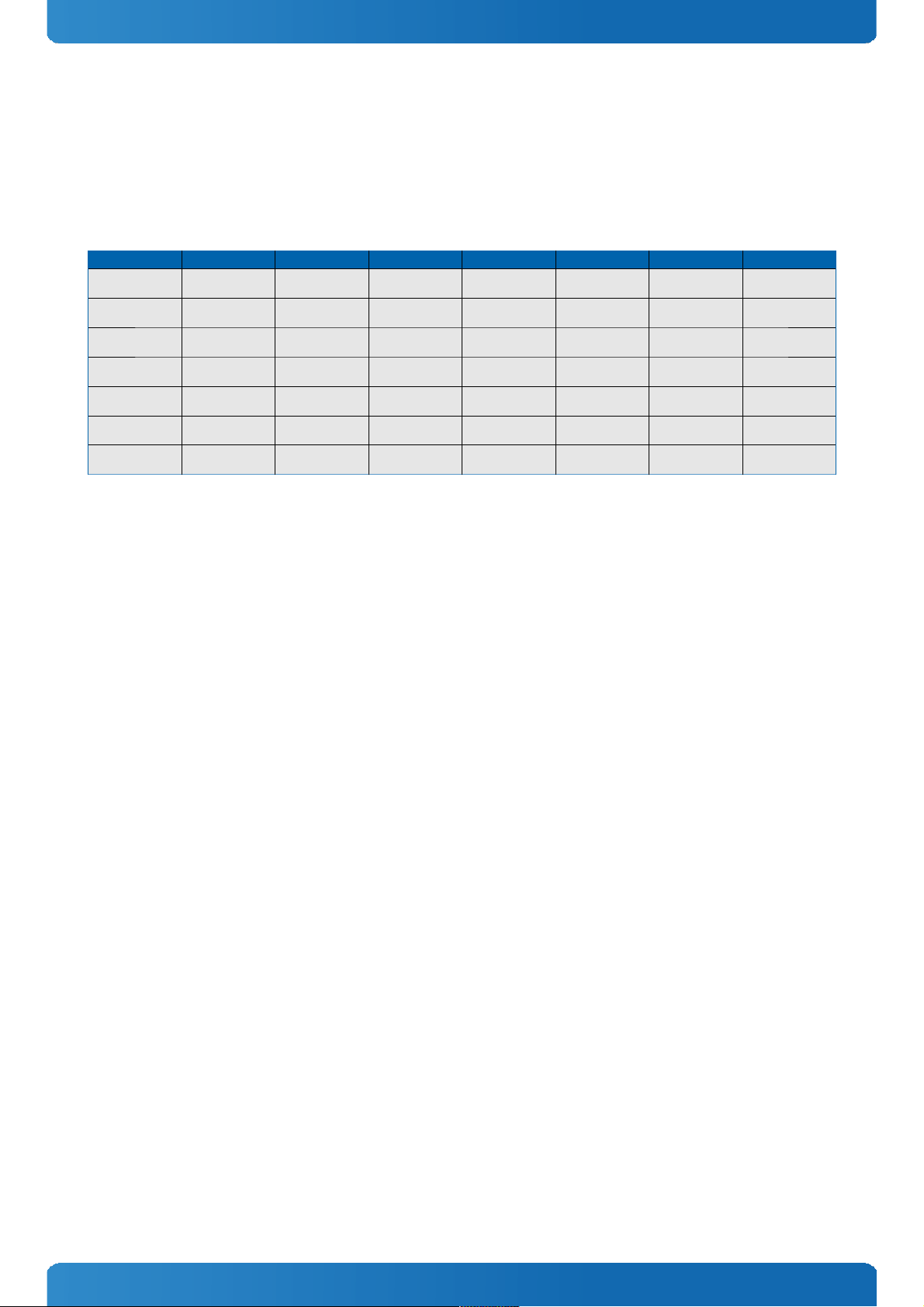
3.1 Modules & Accessories
The SMARC short sized Computer-on-Module SMARC-sXBTi (SXVV) is based on Intel's Bay Trail platform and is available in
different variants to cover the demand of different performance, price and power:
Industrial temperature grade modules (E2: -40°C to +85°C operating)
Part Number Product Name Processor Frequency Memor y ECC eMMC Ethernet
51004-4016-19-4 SMARC-sXBTi
E3845 4E/16GB
BayTrail-I Intel®
Atom E3845
4×1,91GHz 4GB Yes 16GB MLC Intel® i210IT
51004-1040-17-2 SMARC-sXBTi E3827
1E/4S
BayTrail-I Intel®
Atom E3827
2×1,75GHz 1GB Yes 4GB SLC Intel® i210IT
51004-2000-19-4 SMARC-sXBTi
E3845 2GB
BayTrail-I Intel®
Atom E3845
4×1,91GHz 2GB - - Intel® i210IT
51004-2000-17-2 SMARC-sXBTi E3827
2GB
BayTrail-I Intel®
Atom E3827
2×1,75GHz 2GB - - Intel® i210IT
51004-2000-15-2 SMARC-sXBTi E3826
2GB
BayTrail-I Intel®
Atom E3826
2×1,46GHz 2GB - - Intel® i210IT
51004-2000-13-2 SMARC-sXBTi E3825
2GB
BayTrail-I Intel®
Atom E3825
2×1,33GHz 2GB - - Intel® i210IT
51004-1000-15-1 SMARC-sXBTi E3815
1GB
BayTrail-I Intel®
Atom E3815
1×1,46GHz 1GB - - Intel® i210IT
Memory configurations:
» MM = 10: 1024MB DDR3L Memory (8x1Gbit / 128Mx8)
» MM = 20: 2048MB DDR3L Memory (8x2Gbit / 256Mx8)
» MM = 40: 4096MB DDR3L Memory (8x4Gbit / 512Mx8)
» MM = 80: 8192MB DDR3L Memory (8x8Gbit / 1024Mx8) (not available now, will come up in a later release)
Onboard Flash configurations
» FF = 00: without eMMC Flash
» FF = 20: 2GB onboard eMMC Flash
» FF = 40: 4GB onboard eMMC Flash
» FF = 80: 8GB onboard eMMC Flash
» FF = 16: 16GB onboard eMMC Flash
» FF = 32: 32GB onboard eMMC Flash
» FF = 64: 64GB onboard eMMC Flash
Optional hardware features:
» eDP on SMARC Connector, instead of LVDS
» ECC memory
Optional BIOS/Software features:
» AES-NI Support
» FSP with Coreboot
8
Page 9
SMARC-sXBTi / Product Specification
Optional hardware and BIOS features are available project based only for variants not listed
above. Please contact your local sales for customized articles.
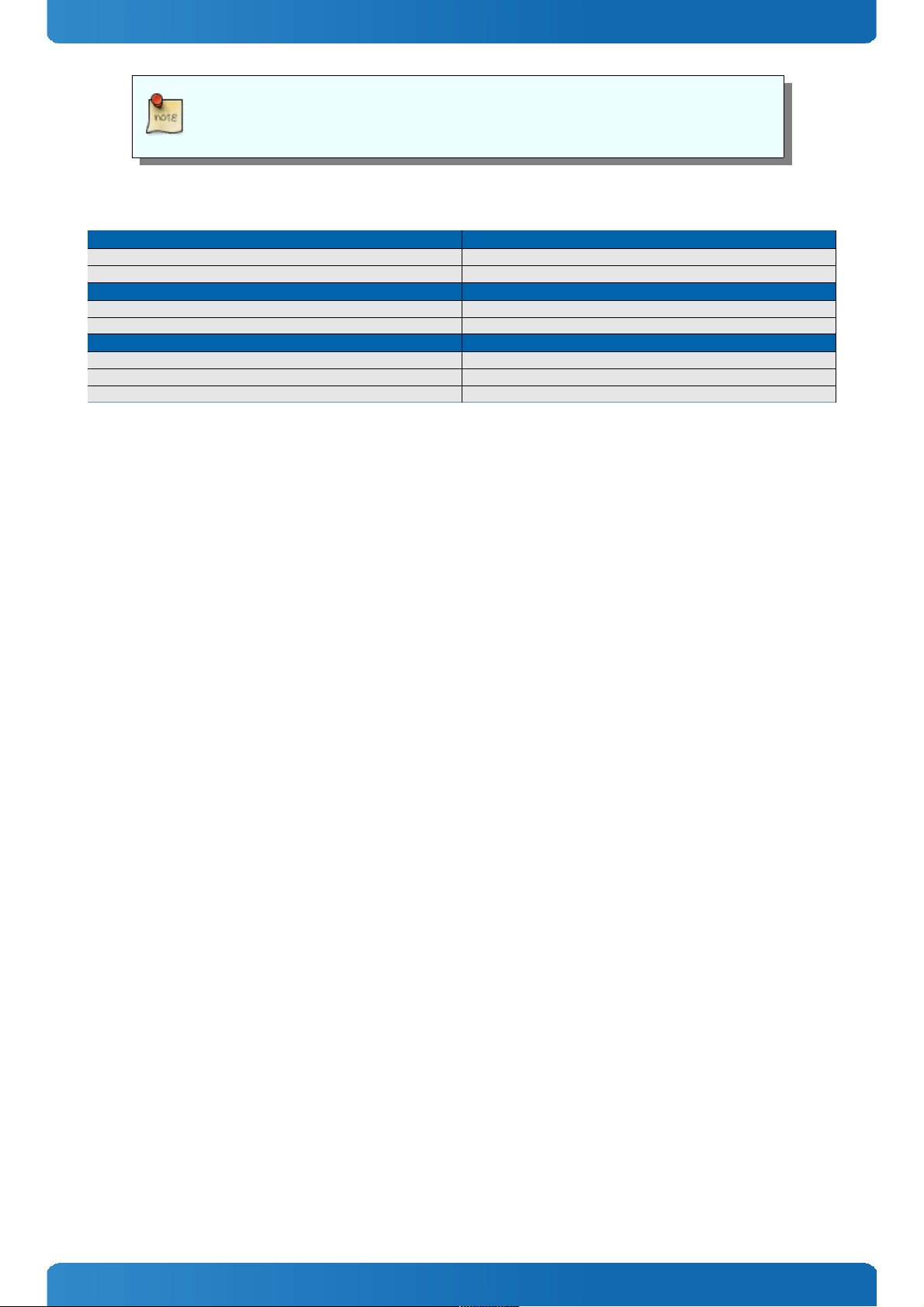
Accessories
Product Number Carrier Boards
51100-0000-00-0 SMARC Evaluation Carrier
51100-0000-00-S SMRAC Starterkit
Product Number Cooling & Mounting
51004-0000-99-1 HSP SMARC-sXBT
51004-0000-99-3 HSK SMARC-sXBT active
Product Number Adapter & Cables
59000-0000-00-0 ADA-SMARC sacrifice
59000-0000-01-0 ADA-SMARC camera1
59200-0000-04-0 KLAS JILI30
9
Page 10
SMARC-sXBTi / Product Specification
3.2 Functional Specification
Processor
The 32nm Intel® ATOM™ / Celeron® (BayTrail-I SOC (Valleyview)) CPU family supports:
» Intel® 64
» Enhanced Intel SpeedStep® Technology
» Thermal Monitoring Technologies
» Execute Disable Bit
» Virtualization Technology VT-x
» 2 Display Pipes for dual independent displays
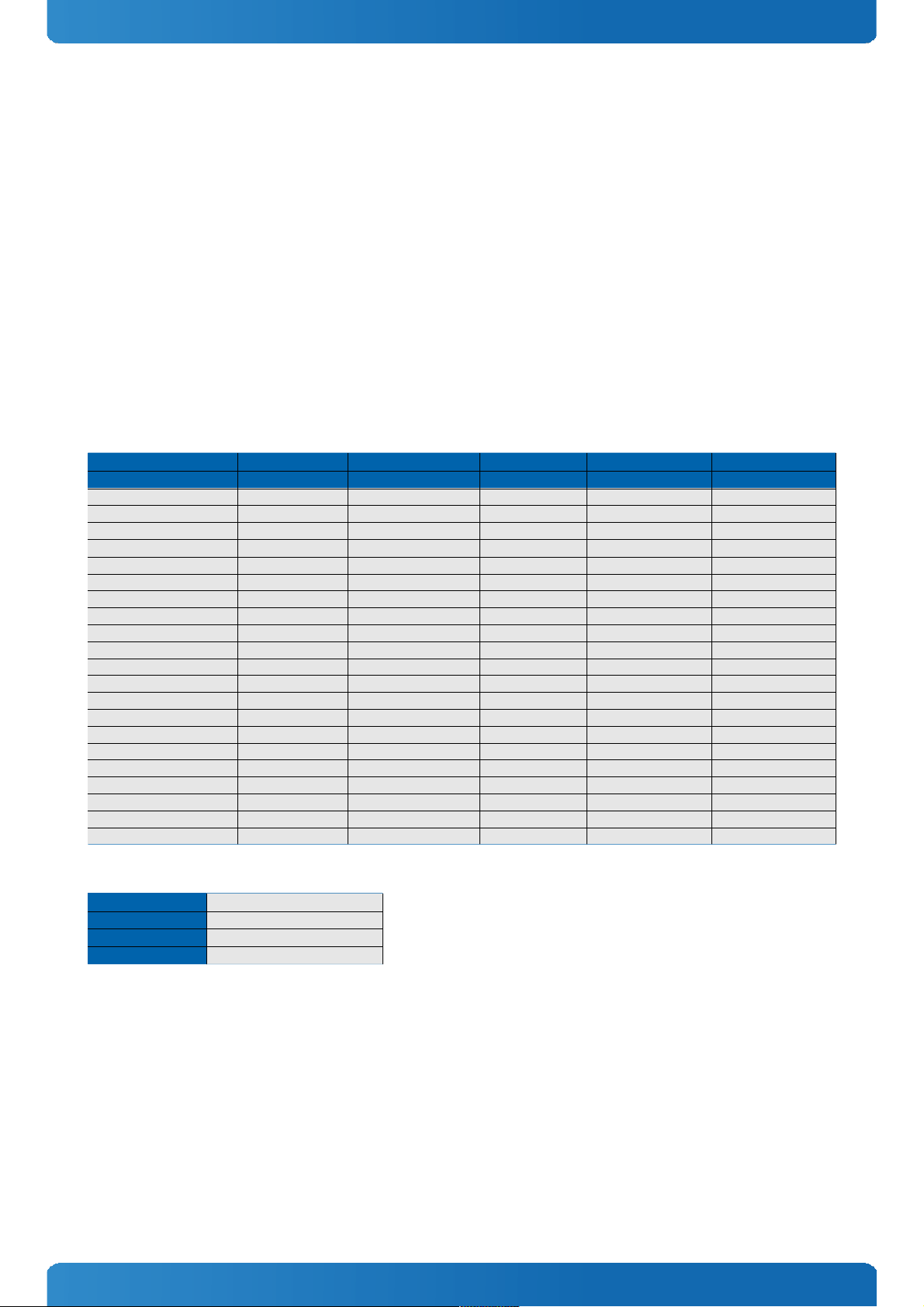
CPU specifications
Intel® Atom™ Atom™ Atom™ Atom™ Atom™
- E3845 E3827 E3826 E3825 E3815
Stepping B3/D0 B3/D0 B3/D0 B3/D0 B3/D0
# of Cores 4 2 2 2 1
# of Threads 4 2 2 2 1
CPU Nominal frequency
1.91GHz 1.75GHz 1.46GHz 1.33GHz 1.46GHz
CPU Burst frequency - - - - -
LFM/LPM Frequency 533MHz 533MHz 533MHz 533MHz 533MHz
Tjunction -40 to 110°C -40 to 110°C -40 to 110°C -40 to 110°C -40 to 110°C
Thermal Design Power (TDP) 10W 8W 7W 6W 5W
SDP - - - - -
Smart Cache 2x1MB 2x512kB 2x512kB 2x512kB 512kB
Memory Type DDR3L-1333 DDR3L-1333 DDR3L-1066 DDR3L-1066 DDR3L-1066
Max Memory Size 8GB 8GB 8GB 8GB 8GB
ECC Memory(optional) Yes Yes Yes Yes Yes
Graphics Model Intel HD® Intel HD® Intel HD® Intel HD® Intel HD®
GFX Base Frequency 542MHz 542MHz 533MHz 533MHz 400MHz
GFX Max Dynamic Frequ. 792MHz 792MHz 667MHz - -
GFX Technology GT1 4EU GT1 4EU GT1 4EU GT1 4EU G T1 4EU
AEC Q100 automtovie Qual. Yes Yes Yes Yes Yes
SDIO Yes Yes Yes Yes Yes
eMMC Yes Yes Yes Yes Yes
AES-NI (optional) Yes Yes Yes Yes Yes
Memory
Sockets
memory down
Memory Type
DDR3L-1066/1333
Maximum Size
2 - 4GB (ECC optional)
Technology
Single Channel (64bit)
10
Page 11
SMARC-sXBTi / Product Specification
Graphics Core
The integrated Intel® HD Graphics (Gen 7) supports:
Execution Units / Pixel Pipelines
4
Max Graphics Memory
tbd
GFX Memory Bandwidth (GB/s)
tbd
GFX Memory Technology
DVMT
API (DirectX/OpenGL)
11 / 3.0 + OCL 1.1
Shader Model
3.0
Hardware accelerated Video
H.264 / MPEG1,2,4 / VC1 / WMV9 / Blu-ray
Independent/Simultaneous Displays
2
Display Port
-
HDCP support
HDCP / PAVP 2
LVDS
LVDS Bits/Pixel
1x18 / 1x24 with DP2LVDS NXP3460
LVDS Bits/Pixel with dithering
-
LVDS max Resolution:
1920x1200
PWM Backlight Control:
YES
Supported Panel Data:
EDID/DID
Display Interfaces
Discrete Graphics
-
Digital Display Interface DDI1
HDMI
Digital Display Interface DDI2
-
Digital Display Interface DDI3
-
Maximum Resolution on DDI
2560x1600@60Hz
Storage
onboard SSD
2-64GB eMMC
SD Card support
yes
IDE Interface
-
Serial-ATA
1x SATA 3Gb/s
SATA AHCI
AHCI
SATA RAID
-
Connectivity
USB 2.0
2x USB 2.0
USB 3.0
1x USB 3.0
USB Client
1 client (optional)
PCI
-
PCI External Masters
-
PCI Express
3x PCIe x1 Gen2
Max PCI Express
-
PCI Express x2/x4 configuration
-
Ethernet
10/100/1000 Mbit
Ethernet controller
Intel® i210IT / i211AT
Ethernet
The Intel® i210IT / i211AT ethernet supports:
» Jumbo Frames
» Time Sync Protocol Indicator
» WOL (Wake On LAN)
» PXE (Preboot eXecution Environment)
11
Page 12

SMARC-sXBTi / Product Specification
Misc Interfaces and Features
Audio
HD Audio and I2S
Onboard Hardware Monitor
NTC7802
Trusted Platform Module
-
Miscellaneous
3x UART / PWM FAN
Kontron Features
External I2C Bus
5 x I2C (PM, CAM, LVDS, GP, HDMI)
M.A.R.S. support
-
Embedded API
KEAPI3 planned
Custom BIOS Settings / Flash Backup
YES
Watchdog support
Yes
Additional features
» All solid capacitors (POSCAP). No tantalum capacitors used.
» Optimized RTC Battery monitoring to secure highest longevity
» Real fast I2C with transfer rates up to 40kB/s.
» Discharge logic on all onboard voltages for highest reliability
Power Features
Singly Supply Support
YES
Supply Voltage
3,0V - 5,25V
ACPI
ACPI 5.0
S-States
S0, S3, S4, S5
S5 Eco Mode
tbd
Misc Power Management
DPST 4.0, iFFS
Power Consumption and Performance
Full Load Power Consumption
tbd
Kontron Performance Index
tbd
Kontron Performance/Watt
tbd
Detailed Power Consumption measurements in all states and bechmarks for CPU, Graphics
and Memory performance are available in Application Note KEMAP054 at EMD Customer
Section.
Supported Operating Systems
The SMARC-sXBTi supports:
» Microsoft Windows 8 32bit/64bit
» Microsoft Windows Embedded Standard 8 (WES8)
» Microsoft Windows 7 32bit/64bit
» Microsoft Windows Embedded Standard 7 (WES7)
» Microsoft Windows Embedded Compact 7 (WEC7)
» Linux
» Android
» WindRiver VxWorks 6.9 32bit/64bit
12
Page 13

SMARC-sXBTi / Product Specification
3.3 Block Diagram
13
Page 14

SMARC-sXBTi / Product Specification
3.4 Electrical Specification
3.4.1 Supply Voltage
Following supply voltage is specified at the SMARC™ connector:
VCC:
3,0V - 5,25V
RTC:
2.5V - 3.3V
3.4.2 Power Supply Rise Time
» The input voltages shall rise from ≤10% of nominal to within the regulation ranges within 0.1ms to 20ms.
» There must be a smooth and continuous ramp of each DC input voltage from 10% to 90% of its final set-point
3.4.3 Supply Voltage Ripple
» Maximum 100 mV peak to peak 0 – 20 MHz
3.4.4 Power Consumption
The maximum Power Consumption of the different SMARC-sXBTi variants is tbd (100% CPU load on all cores; 90°C CPU
temperature). Further information with detailed measurements are available in Application Note KEMAP054 available on
EMD Customer Section. Information there is available after registration.
14
Page 15

SMARC-sXBTi / Product Specification
3.5 Power Control
Power Supply
The SMARC-sXBTi supports a power input from 3,0V - 5,25V. The supply voltage is applied through the VCC pins (VCC) of
the module connector.
Power Button (PWR_BTN#)
The power button (Pin P128) is available through the module connector described in the pinout list. To start the module
via Power Button the PWRBTN# signal must be at least 50ms (50ms ≤ t < 4s, typical 400ms) at low level (Power Button
Event).
Pressing the power button for at least 4seconds will turn off power to the module (Power Button Override).
CB_POWER_BAD#
The SMARC-sXBTi provides an external input for a Carrier Board Power Bad signal (Pin S150). The implementation of this
subsystem complies with the COM Express® Specification. CB_POWER_BAD# is internally pulled up to 3.3V and must be
high level to power on the module.
Reset Button (RST_CB_IN#)
The reset button (Pin P127) is available through the module connector described in the pinout list. The module will stay in
reset as long as RST_CB_IN# is grounded.
15
Page 16

SMARC-sXBTi / Product Specification
3.6 Environmental Specification
3.6.1 Temperature Specification
General Specification Operating Non-operating
Commercial grade 0°C to +60°C -30°C to +85°C
Extended (E1) -25°C to +75°C -30°C to +85°C
Industrial grade (E2) -40°C to +85°C -40°C to +85°C
Standard modules are available for industrial grade temperature range. Please see chapter
Product Specification for available variants for extended or commercial temperate grade
With Kontron heatspreader plate assembly
The operating temperature defines two requirements:
» the maximum ambient temperature with ambient being the air surrounding the module.
» the maximum measurable temperature on any spot on the heatspreader's surface
Without Kontron heatspreader plate assembly
The operating temperature is the maximum measurable temperature on any spot on the module's surface.
3.6.2 Humidity
» Operating: 10% to 90% (non condensing)
» Non operating: 5% to 95% (non condensing)
16
Page 17

SMARC-sXBTi / Product Specification
3.7 Standards and Certifications
RoHS
The SMARC-sXBTi
is compliant to the directive 2002/95/EC on the restriction of the use of certain hazardous substances (RoHS) in electrical
and electronic equipment.
CE marking
The SMARC-sXBTi
is CE marked according to Low Voltage Directive 2006/95/EC – Test standard EN60950
WEEE Directive
WEEE Directive 2002/96/EC is not applicable for Computer-on-Modules.
Conformal Coating
Conformal Coating is available for Kontron Computer-on-Modules and for validated SO-DIMM memory modules. Please
contact your local sales or support for further details.
EMC
Validated in Kontron reference housing for EMC the SMARC-sXBTi follows the requirements for electromagnetic
compatibility standards
» EN55022
17
Page 18

SMARC-sXBTi / Product Specification
3.8 MTBF
The following MTBF (Mean Time Before Failure) values were calculated using a combination of manufacturer’s test data, if
the data was available, and the Telcordia (Bellcore) issue 2 calculation for the remaining parts.
The calculation method used is “Telcordia Method 1 Case 3” in a ground benign, controlled environment (GB,GC). This
particular method takes into account varying temperature and stress data and the system is assumed to have not been
burned in.
Other environmental stresses (extreme altitude, vibration, salt water exposure, etc) lower MTBF values.
System MTBF (hours): tbd
Fans usually shipped with Kontron Europe GmbH products have 50,000-hour typical
operating life. The above estimates assume no fan, but a passive heat sinking arrangement
Estimated RTC battery life (as opposed to battery failures) is not accounted for in the above
figures and need to be considered separately. Battery life depends on both temperature
and operating conditions. When the Kontron unit has external power; the only battery
drain is from leakage paths.
18
Page 19

SMARC-sXBTi / Product Specification
3.9 Mechanical Specification
3.9.1 Module Dimension
» 50mm x 82mm
3.9.2 Height on Top
» Maximum 3.0mm (without printed circuit board)
» Height is depending on (optional) CPU cooler / heat spreader
3.9.3 Height on Bottom
» Maximum approx. 1.3mm (without printed circuit board)
3.9.4 Mechanical Drawing
All dimensions are shown in millimeters. Tolerances should be ± 0.25mm [±0.010”], unless otherwise noted.
CAD drawings will be available at EMD CustomerSection
19
Page 20

SMARC-sXBTi / Product Specification
3.10 Module Dimensions
All dimensions in mm
20
Page 21

SMARC-sXBTi / Product Specification
3.11 Thermal Management, Heatspreader and Cooling Solutions
A heatspreader plate assembly is available from Kontron Europe GmbH for the SMARC-sXBTi. The heatspreader plate on top
of this assembly is NOT a heat sink. It works as a SMARC-standard thermal interface to use with a heat sink or external
cooling devices.
External cooling must be provided to maintain the heatspreader plate at proper operating temperatures. Under worstcase conditions, the cooling mechanism must maintain an ambient air and heatspreader plate temperature on any spot of
the heatspreader's surface according the module specifications:
» 60°C for commercial grade modules
» 75°C for extended temperature grade modules (E1)
» 85°C for industrial temperature grade modules (E2/XT)
The aluminum slugs and thermal pads or the heat-pipe on the underside of the heatspreader assembly implement thermal
interfaces between the heatspreader plate and the major heat-generating components on the SMARC-sXBTi. About 80
percent of the power dissipated within the module is conducted to the heatspreader plate and can be removed by the
cooling solution.
You can use many thermal-management solutions with the heatspreader plates, including active and passive approaches.
The optimum cooling solution varies, depending on the SMARC application and environmental conditions. Active or
passive cooling solutions provided from Kontron Europe GmbH for the SMARC-sXBTi are usually designed to cover the
power and thermal dissipation for a commercial grade temperature range used in a housing with proper air flow.
Documentation and CAD drawings of SMARC-sXBTi heatspreader and cooling solutions are provided at
http://emdcustomersection.kontron.com.
21
Page 22

SMARC-sXBTi / Features and Interfaces
4 Features and Interfaces
4.1 Onboard eMMC Flash
The SMARC-sXBTi features a 14x18mm onboard Micron NAND Flash drive with capacities of 2-64GB eMMC. The Flash drive
includes a Phison PS8200 micro controller and supports:
» JEDEC/MMC standard version 4.41 compliant
» class 0 (basic); class 2 (block, read); class 4 (block write); class 5 (erase); class 6 (write protect); class 7 (lock card)
» MMCplus™ and MMCmobile™ protocols
» 52 MHz clock speed (MAX)
» Boot operation (high-speed boot)
» Sleep mode
» Replay-protected memory block (RPMB)
» Secure erase and trim
» Permanent and power-on write protection
» Double data rate (DDR) function
» Wear Leveling, ECC and block management
» -40°C to +85°C indutrial temperature range
» Multi-Level-Cell (MLC) technology
» Single-Level-Cell (SLC) technology optional by firmware re-configuration during SMARC-sXBTi manufacturing
Flash Part No. MTFC4GMVEA-4M IT MTFC8GLVEA-4M IT MTFC16GJVEC-4M IT MTFC32GJVED-4M IT MTFC64GJVDN-4M IT
Nominal Flash Size MLC 4GByte 8GByte 16GByte 32GByte 64GByte
Nominal Flash Size SLC 2GByte 4GByte 8GByte 16GByte 32GByte
Sequential MLC read
speed
44 MB/s 44 MB/s 44 MB/s 44 MB/s 44 MB/s
Sequential MLC write
speed
13.5 MB/s 13.5 MB/s 20 MB/s 20MB/s 20 MB/s
I/O Performance
read/write
1100 / 100 IOPS 1100 / 100 IOPS 1100 / 100 IOPS 1100 / 100 IOPS 1100 / 100 IOPS
Endurance (# of P/E
cycles)
MLC: 3k
SLC: 60k
MLC: 3k
SLC: 60k
MLC: 3k
SLC: 60k
MLC: 3k
SLC: 60k
MLC: 3k
SLC: 60k
Notes:
» Random access of 4KB chunk, sequential read access of 1MB chunk
» Data based on Datasheet Micron eMMC Rev.B from 2/2012
» ~10% of the nominal flash size are reserved for Firmware and Block Management
4.2 Secure Digital Card
The SMARC-sXBTi supports an SDIO Interface to be used for micro/mini/standard SD Card sockets. Following SD Cards are
validated from Kontron and recommended for use:
swissbit® S-200U & S-300U Series Industrial microSD Card
» compliant to SD Card specification 2.0
» Wear Leveling of static and dynamic data
22
Page 23

SMARC-sXBTi / Features and Interfaces
» High reliability (MTBF >3,000,000 hours, > 10,000 insertions)
» Extended or Industrial Temperature range
» up to 25MB/s data transfer speed
Delkin Devices Inc. MicroSD
» compliant to SD Card specification 2.0
» Wear Leveling and ECC
» High reliability (MTBF >2,000,000 hours, > 2,000,000 write/erase cycles)
» Industrial Temperature range
» up to 17MB/s data transfer speed
Order information
Density Manufacturerer & Part.No. Temperature range mSD-SD Adapter
1GB SD1.1 swissbit SFSD1024N1BN1TO-I-DF-151-
STD
-40°C to 85°C No
2GB SD1.1 swissbit SFSD2048N1BW1MT-E-ME-111-
STD
-25°C to 85°C No
2GB SD1.1 Delkin SD02GHMSH-S2047-B -40°C to 85°C No
2GB SDHC Delkin SD02GHMSH-S2000-B -40°C to 85°C Yes
4GB SDHC swissbit SFSD4096N1BW1MT-E-DF-111-
STD
-25°C to 85°C No
4GB SDHC Delkin SD04GHMSH-S2647-B -40°C to 85°C No
4GB SDHC Delkin SD04GHMSH-S2600-B -40°C to 85°C Yes
8GB SDHC Delkin SD08GHMSH-S2647-B -40°C to 85°C No
8GB SDHC Delkin SD08GHMSH-S2600-B -40°C to 85°C Yes
4.3 S5 Eco Mode
Kontron’s new high-efficient power-off state S5 Eco enables lowest power-consumption in soft-off state – less than 1 mA
compared to the regular S5 state this means a reduction by at least factor 200!
In the “normal” S5 mode the board is supplied by 5V_Stb and needs usually up to 300mA just to stay off. This mode allows
to be switched on by power button, RTC event and WakeOnLan, even when it is not necessary. The new S5 Eco mode
reduces the current enormous.
The S5 Eco Mode can be enabled in BIOS Setup, when the BIOS supports this feature.
Following prerequisites and consequences occur when S5 Eco Mode is enabled
» The power button must be pressed at least for 200ms to switch on.
» Wake via Power button only.
» “Power On After Power Fail”/“State after G3”: only “stay off” is possible
23
Page 24

SMARC-sXBTi / Features and Interfaces
4.4 Speedstep Technology
The Intel® processors offer the Intel® Enhanced SpeedStep™ technology that automatically switches between maximum
performance mode and battery-optimized mode, depending on the needs of the application being run. It enables you to
adapt high performance computing on your applications. When powered by a battery or running in idle mode, the
processor drops to lower frequencies (by changing the CPU ratios) and voltage, conserving battery life while maintaining
a high level of performance. The frequency is set back automatically to the high frequency, allowing you to customize
performance.
In order to use the Intel® Enhanced SpeedStep™ technology the operating system must support SpeedStep™ technology.
By deactivating the SpeedStep feature in the BIOS, manual control/modification of CPU performance is possible. Setup
the CPU Performance State in the BIOS Setup or use 3rd party software to control CPU Performance States.
24
Page 25

SMARC-sXBTi / Features and Interfaces
4.5 C-States
New generation platforms include power saving features like SuperLFM, EIST (P-States) or C-States in O/S idle mode.
Activated C-States are able to dramatically decrease power consumption in idle mode by reducing the Core Voltage or
switching of parts of the CPU Core, the Core Clocks or the CPU Cache.
Following C-States are defined:
C-State Description Function
C0 Operating CPU fully turned on
C1 Halt State Stops CPU main internal clocks via software
C1E Enhanced Halt Similar to C1, additionally reduces CPU voltage
C2 Stop Grant Stops CPU internal and external clocks via hardware
C2E Extended Stop Grant Similar to C2, additionally reduces CPU voltage
C3 Deep Sleep Stops all CPU internal and external clocks
C3E Extended Stop Grant Similar to C3, additionally reduces CPU voltage
C4 Deeper Sleep Reduces CPU voltage
C4E Enhanced Deeper Sleep Reduces CPU voltage even more and turns off the
memory cache
C6 Deep Power Down Reduces the CPU internal voltage to any value,
including 0V
C7 Deep Power Down Similar to C6, additionally LLC (LastLevelCache) is
switched off
C-States are usually enabled by default for low power consumption, but active C-States my influence performance
sensitive applications or real-time systems.
» Active C6-State may influence data transfer on external Serial Ports
» Active C7-State may cause lower CPU and Graphics performance
It's recommended to disable C-States / Enhanced C-States in BIOS Setup if any problems occur.
25
Page 26

SMARC-sXBTi / Features and Interfaces
4.6 Graphics Features
The integrated Intel® HD Graphics (Gen 7) graphics supports following OS dependent featureset:
O/S Win8 Win7/WES7 WEC7 Linux (Fedora/Yocto) Linux (Tizen) Android
Display Interfaces*
HDMI 1.4a, DP 1.1a, eDP 1.3, VGA HDMI, eDP
Max HDMI/DVI
Resolution
1920×1200
Max DP Resolution
2560×1600 -
Max VGA Resolution*
2560×1600 -
Dual Independent
Display
Yes
2D HW acceleration
DirectDraw X Server Wayland Compositor OpenGL Renderer
3D HW acceleration
OGL4.0, DX11.1/10/9 OGLES 2.0 OGL3.2/OGLES2.0 OGLES 1.1/2.0 in 4.2
JellyBean
OGLES 1.1/2.0/3.0 in
4.4 KitKat
HW Media
Acceleration
DXVA 2 DirectShow VAAPI OpenMax
HW Video Decode
H.264,MPEG2,VC1,VP8 H.264,MPEG2,VC1 H.264,MPEG2,VC1,VP8 H.264,MPEG2,VC1,VP8
HW Video Encode
tbd tbd - H.264,MPEG2 H.264,MPEG2
Blu-Ray
v2.0 - - - -
Media players
Windows Media Player
PowerDVD 10
CEPlayer GStreamer - VAAPI
* Module Form Factor / Featureset dependent, please check module specification for supported interfaces
26
Page 27

SMARC-sXBTi / Features and Interfaces
4.7 ACPI Suspend Modes and Resume Events
The SMARC-sXBTi supports the S-states S0, S3, S4, S5. S5eco Support: tbd
The following events resume the system from S3:
» USB Keyboard (1)
» USB Mouse (1)
» Power Button
» WakeOnLan (2)
The following events resume the system from S4:
» Power Button
» WakeOnLan (2)
The following events resume the system from S5:
» Power Button
» WakeOnLan (2)
The following events resume the system from S5Eco:
» Power Button
(1) OS must support wake up via USB devices and baseboard must power the USB Port with
StBy-Voltage
(2) Depending on the Used Ethernet MAC/Phy WakeOnLan must be enabled in BIOS setup
and driver options
27
Page 28

SMARC-sXBTi / Connectors
5 Connectors
The pinouts for Interface Connector are documented for convenient reference. Please see the SMARC Specification and
SMARC Design Guide for detailed, design-level information.
5.1 SMARC™ Connector Top Side
Pin Signal Module Direction Module
Termination
Type/Tolerance Controller Controller Pin
Name
Power Rail
P1 PCAM_PXL_CK1 NC - - - - -
P2 GND - - - - - -
P3 CSI1_CK+ /
PCAM_D0
In - LVDS D-PHY /
VDD_IO
ValleyView MCSI1_CLKP V_1V24_S0
P4 CSI1_CK- /
PCAM_D1
In - LVDS D-PHY /
VDD_IO
ValleyView MCSI1_CLKN V_1V24_S0
P5 PCAM_DE - - - - - -
P6 PCAM_MCK - - - - - -
P7 CSI1_D0+ /
PCAM_D2
In - LVDS D-PHY /
VDD_IO
ValleyView MCSI1_DP0 V_1V24_S0
P8 CSI1_D0- /
PCAM_D3
In - LVDS D-PHY /
VDD_IO
ValleyView MCSI1_DN0 V_1V24_S0
P9 GND - - - - - -
P10 CSI1_D1+ /
PCAM_D4
In - LVDS D-PHY /
VDD_IO
ValleyView MCSI1_DP1 V_1V24_S0
P11 CSI1_D1- /
PCAM_D5
In - LVDS D-PHY /
VDD_IO
ValleyView MCSI1_DN1 V_1V24_S0
P12 GND - - - - - -
P13 CSI1_D2+ /
PCAM_D6
In - LVDS D-PHY /
VDD_IO
ValleyView MCSI1_DP2 V_1V24_S0
P14 CSI1_D2- /
PCAM_D7
In - LVDS D-PHY /
VDD_IO
ValleyView MCSI1_DN2 V_1V24_S0
P15 GND - - - - - -
P16 CSI1_D3+ /
PCAM_D8
IN - LVDS D-PHY /
VDD_IO
ValleyView MCSI1_DP3 V_1V24_S0
P17 CSI1_D3- /
PCAM_D9
IN - LVDS D-PHY /
VDD_IO
ValleyView MCSI1_DN3 V_1V24_S0
P18 GND - - - - - -
P19 GBE_MDI3- Bi-Dir - GBE MDI Springville i210 MDI3- -
P20 GBE_MDI3+ Bi-Dir - GBE MDI Spr ingville i210 MDI3+ -
P21 GBE_LINK100# Out / OD - VDD_IO Spr ingville i210 LED1 V_3V3_GBE
P22 GBE_LINK1000# Out / OD - VDD_IO Springville i210 LED2 V_3V3_GBE
P23 GBE_MDI2- Bi-Dir - GBE MDI Springville i210 MDI2- -
P24 GBE_MDI2+ Bi-Dir - GBE MDI Spr ingville i210 MDI2+ -
P25 GBE_LINK_ACT# Out / OD - VDD_IO Springville i210 LED0 V_3V3_GBE
P26 GBE_MDI1- Bi-Dir - GBE MDI Springville i210 MDI1- -
P27 GBE_MDI1+ Bi-Dir - GBE MDI Spr ingville i210 MDI1+ -
P28 GBE_CTREF - - - - - -
P29 GBE_MDI0- Bi-Dir - GBE MDI Springville i210 MDI0- -
P30 GBE_MDI0+ Bi-Dir - GBE MDI Spr ingville i210 MDI0+ -
P31 SPI0_CS1# - PU-100k CMOS / VDD_IO - - V_1V8_S0
P32 GND - - - - - -
P33 SDIO_WP In - CMOS 3.3V ValleyView SD3_WP V_1V8_S0
P34 SDIO_CMD Bi-Dir Series-22Ohm +
PU-20k
CMOS 3.3V ValleyView SD3_CMD V_3V3_S0
P35 SDIO_CD# In - CMOS 3.3V ValleyView SD3_CD# V_1V8_S0
P36 SDIO_CK Out Series-22Ohm +
PD-20k
CMOS 3.3V ValleyView SD3_CLK V_3V3_S0
P37 SDIO_PWR_EN Out - CMOS 3.3V ValleyView SD3_PWREN# V_1V8_S0
P38 GND - - - - - -
P39 SDIO_D0 Bi-Dir PU-20k CMOS 3.3V ValleyView SD3_D0 V_3V3_S0
P40 SDIO_D1 Bi-Dir PU-20k CMOS 3.3V ValleyView SD3_D1 V_3V3_S0
P41 SDIO_D2 Bi-Dir PU-20k CMOS 3.3V ValleyView SD3_D2 V_3V3_S0
P42 SDIO_D3 Bi-Dir PU-20k CMOS 3.3V ValleyView SD3_D3 V_3V3_S0
P43 SPI0_CS0# Out Series-22Ohm CMOS / 1.8V ValleyView PCU_SPI_CS1# V_VIO_S0
P44 SPI0_CK Out Series-22Ohm CMOS / 1.8V ValleyView PCU_SPI_CLK V_VIO_S0
P45 SPI0_DIN In Series-22Ohm CMOS / 1.8V ValleyView PCU_SPI_MISO V_VIO_S0
P46 SPI0_DO Out Series-22Ohm CMOS / 1.8V ValleyView PCU_SPI_MOSI V_VIO_S0
P47 GND - - - - - -
P48 SATA_TX+ Out Serial 10nF SATA ValleyView SATA_TXP0 -
P49 SATA_TX- Out Serial 10nF SATA ValleyView SATA_TXN0 -
28
Page 29

SMARC-sXBTi / Connectors
P50 GND - - - - - -
P51 SATA_RX+ In Serial 10nF SATA ValleyView SATA_RXP0 -
P52 SATA_RX- In Serial 10nF SATA ValleyView SATA_RXN0 -
P53 GND - - - - - -
P54 SPI1_CS0# Out Series-33.2Ohm CMOS / 1.8V ValleyView SIO_SPI_CS# V_1V8_S0
P55 SPI1_CS1# - PU-100k CMOS / VDD_IO - - V_1V8_S0
P56 SPI1_CK Out Series-33.2Ohm CMOS / 1.8V ValleyView SIO_SPI_CLK V_1V8_S0
P57 SPI1_DIN In - CMOS / 1.8V ValleyView SIO_SPI_MISO V_1V8_S0
P58 SPI1_DO Out Series-33.2Ohm CMOS / 1.8V ValleyView SIO_SPI_MOSI V_1V8_S0
P59 GND - - - - - -
P60 USB0+ Bi-Dir - USB TUSB1211A1ZRQ DP -
P61 USB0- Bi-Dir - USB TUSB1211A1ZRQ DM -
P62 USB0_EN_OC# Bi-Dir / OD PU-CPLD-5-25k CMOS 3.3V TUSB1211+CPLD FAULT/PSW V_1V8_S5
P63 USB0_VBUS_DET In - CMOS 5.0V TUSB1211A1ZRQ VBUS V_1V8_S5
P64 USB0_OTG_ID In - CMOS 3.3V TUSB1211A1ZRQ ID V_1V8_S5
P65 USB1+ Bi-Dir - USB ValleyView USB_DP2 -
P66 USB1- Bi-Dir - USB ValleyView USB_DN2 -
P67 USB1_EN_OC# Bi-Dir PU-CPLD-10k CMOS 3.3V CPLD IO_H2 V_3V3_REG_S5
P68 GND - - - - - -
P69 USB2+ Bi-Dir - USB ValleyView USB_DP3 -
P70 USB2- Bi-Dir - USB ValleyView USB_DN3 -
P71 USB2_EN_OC# Bi-Dir PU-CPLD-10k CMOS 3.3V CPLD IO_D3 V_3V3_REG_S5
P72 PCIE_C_PRSNT# In PU-10k CMOS 3.3V ValleyView ILB_LPC_SERIRQ V_1V8_S0
P73 PCIE_B_PRSNT# In PU-10k CMOS 3.3V ValleyView ILB_LPC_CLK0 V_1V8_S0
P74 PCIE_A_PRSNT# In PU-10k CMOS 3.3V ValleyView ILB_LPC_AD3 V_1V8_S0
- <Key> - - - - - -
P75 PCIE_A_RST# Out - CMOS 3.3V ValleyView PMC_PLTRST# V_1V8_S0
P76 PCIE_C_CKREQ# In PU-10k CMOS 3.3V ValleyView PCIE_CLKREQ2# V_1V8_S0
P77 PCIE_B_CKREQ# In PU-10k CMOS 3.3V ValleyView PCIE_CLKREQ1# V_1V8_S0
P78 PCIE_A_CKREQ# In PU-10k CMOS 3.3V ValleyView PCIE_CLKREQ0# V_1V8_S0
P79 GND - - - - - -
P80 PCIE_C_REFCK+ Out - LVDS PCIe ValleyView PCIE_CLKP2 -
P81 PCIE_C_REFCK- Out - LVDS PCIe ValleyView PCIE_CLKN2 -
P82 GND - - - - - -
P83 PCIE_A_REFCK+ Out - LVDS PCIe ValleyView PCIE_CLKP0 -
P84 PCIE_A_REFCK- Out - LVDS PCIe ValleyView PCIE_CLKN0 -
P85 GND - - - - - -
P86 PCIE_A_RX+ In - LVDS PCIe ValleyView PCIE_RXP0 -
P87 PCIE_A_RX- In - LVDS PCIe ValleyView PCIE_RXN0 -
P88 GND - - - - - -
P89 PCIE_A_TX+ Out Serial-100nF LVDS PCIe ValleyView PCIE_TXP0 -
P90 PCIE_A_TX- Out Serial-100nF LVDS PCIe ValleyView PCIE_TXN0 -
P91 GND - - - - - -
P92 HDMI_D2+ Out - TMDS PTN3360B Shifter OUT_D4+ -
P93 HDMI_D2- Out - TMDS PTN3360B Shifter OUT_D4- -
P94 GND - - - - - -
P95 HDMI_D1+ Out - TMDS PTN3360B Shifter OUT_D3+ -
P96 HDMI_D1- Out - TMDS PTN3360B Shifter OUT_D3- -
P97 GND - - - - - -
P98 HDMI_D0+ Out - TMDS PTN3360B Shifter OUT_D2+ -
P99 HDMI_D0- Out - TMDS PTN3360B Shifter OUT_D2- -
P100 GND - - - - - -
P101 HDMI_CK+ Out - TMDS PTN3360B Shif ter OUT_D1+ -
P102 HDMI_CK- Out - TMDS PTN3360B Shifter OUT_D1- -
P103 GND - - - - - -
P104 HDMI_HPD In PU-100k CMOS 1.8V PTN3360B Shifter HPD_SINK V_1V8_S0
P105 HDMI_CTRL_CK Out PU-100k CMOS 1.8V PTN3360B Shifter SCL_SINK V_1V8_S0
P106 HDMI_CTRL_DAT Bi-Dir PU-100k CMOS 1.8V PTN3360B Shifter SDA_SINK V_1V8_S0
P107 HDMI_CEC - - - - - -
P108 GPIO0 /
CAM0_PWR#
Bi-Dir PU-SoC-20k CMOS / 1.8V ValleyView GPIO_S0_SC_88 V_1V8_S0
P109 GPIO1 /
CAM1_PWR#
Bi-Dir PU-SoC-20k CMOS / 1.8V ValleyView GPIO_S0_SC_89 V_1V8_S0
P110 GPIO2 /
CAM0_RST#
Bi-Dir PU-SoC-20k CMOS / 1.8V ValleyView GPIO_S0_SC_91 V_1V8_S0
P111 GPIO3 /
CAM1_RST#
Bi-Dir PU-SoC-20k CMOS / 1.8V ValleyView GPIO_S0_SC_90 V_1V8_S0
P112 GPIO4 / HDA_RST# Bi-Dir PU-SoC-20k CMOS / 1.8V ValleyView GPIO_S0_SC_59 V_1V8_S0
P113 GPIO5 / PWM_OUT Bi-Dir PU-SoC-20k CMOS / 1.8V ValleyView GPIO_S0_SC_93 V_1V8_S0
29
Page 30

SMARC-sXBTi / Connectors
P114 GPIO6 / TACHIN Bi-Dir PU-SoC-20k CMOS / 1.8V ValleyView GPIO_S0_SC_92 V_1V8_S0
P115 GPIO7 / PCAM_FLD Bi-Dir PU-SoC-20k CMOS / 1.8V ValleyView GPIO_S0_SC_97 V_1V8_S0
P116 GPIO8 / CAN0_ERR
#
Bi-Dir PU-SoC-20k CMOS / 1.8V ValleyView GPIO_S0_SC_98 V_1V8_S0
P117 GPIO9 / CAN1_ERR
#
Bi-Dir PU-SoC-20k CMOS / 1.8V ValleyView GPIO_S0_SC_99 V_1V8_S0
P118 GPIO10 Bi-Dir PU-SoC-20k CMOS / 1.8V ValleyView GPIO_S0_SC_100 V_1V8_S0
P119 GPIO11 Bi-Dir PU-SoC-20k CMOS / 1.8V ValleyView GPIO_S0_SC_101 V_1V8_S0
P120 GND - - - - - -
P121 I2C_PM_CK Out PU-2k2 CMOS 1.8V ValleyView SIO_I2C_DATA_/_G
PIO_S0_SC_79
V_1V8_S0
P122 I2C_PM_DAT Bi-Dir PU-2k2 CMOS 1.8V ValleyView SIO_I2C_DATA_/_G
PIO_S0_SC_79
V_1V8_S0
P123 BOOT_SEL0# In PU-SoC-20k CMOS / 1.8V ValleyView GPIO_S5_0 V_1V8_S5
P124 BOOT_SEL1# In PU-SoC-20k CMOS / 1.8V ValleyView GPIO_S5_8 V_1V8_S5
P125 BOOT_SEL2# In PU-SoC-20k CMOS / 1.8V ValleyView GPIO_S5_10 V_1V8_S5
P126 RESET_OUT# Out CPLD-Wpu CMOS / 1.8V CPLD IO_B5 V_1V8_REG_S5
P127 RESET_IN# In PU-CPLD-20k CMOS / 1.8V CPLD IO_J10 V_1V8_REG_S5
P128 POWER_BTN# In PU-CPLD-20k CMOS / 1.8V CPLD IO_E10 V_1V8_REG_S5
P129 SER0_TX Out SoC 20k PU CMOS / VDD_IO ValleyView SIO_UART1_TXD V_1V8_S0
P130 SER0_RX In SoC 20k PU CMOS / VDD_IO ValleyView SIO_UART1_RXD V_1V8_S0
P131 SER0_RTS# Out SoC 20k PU CMOS / VDD_IO ValleyView SIO_UART1_RTS# V_1V8_S0
P132 SER0_CTS# In SoC 20k PU CMOS / VDD_IO ValleyView SIO_UART1_CTS# V_1V8_S0
P133 GND - - - - - -
P134 SER1_TX Out SoC 20k PU CMOS / VDD_IO ValleyView GPIO_S0_SC_57 V_1V8_S0
P135 SER1_RX In SoC 20k PU CMOS / VDD_IO ValleyView GPIO_S0_SC_61 V_1V8_S0
P136 SER2_TX Out SoC 20k PU CMOS / VDD_IO ValleyView SIO_UART2_TXD V_1V8_S0
P137 SER2_RX In SoC 20k PU CMOS / VDD_IO ValleyView SIO_UART2_RXD V_1V8_S0
P138 SER2_RTS# Out SoC 20k PU CMOS / VDD_IO ValleyView SIO_UART2_RTS# V_1V8_S0
P139 SER2_CTS# In SoC 20k PU CMOS / VDD_IO ValleyView SIO_UART2_CTS# V_1V8_S0
P140 SER3_TX NC - - - - -
P141 SER3_RX NC - - - - -
P142 GND - - - - - -
P143 CAN0_TX NC - - - - -
P144 CAN0_RX NC - - - - -
P145 CAN1_TX NC - - - - -
P146 CAN1_RX NC - - - - -
P147 VDD_IN PWR - - - - 3.0V-5.25V
P148 VDD_IN PWR - - - - 3.0V-5.25V
P149 VDD_IN PWR - - - - 3.0V-5.25V
P150 VDD_IN PWR - - - - 3.0V-5.25V
P151 VDD_IN PWR - - - - 3.0V-5.25V
P152 VDD_IN PWR - - - - 3.0V-5.25V
P153 VDD_IN PWR - - - - 3.0V-5.25V
P154 VDD_IN PWR - - - - 3.0V-5.25V
P155 VDD_IN PWR - - - - 3.0V-5.25V
P156 VDD_IN PWR - - - - 3.0V-5.25V
5.2 SMARC™ Connector Bottom Side
Pin Signal Module Direction Module
Termination
Type/Tolerance Controller Controller Pin
Name
Power Rail
S1 PCAM_VSYNC - - - - - -
S2 PCAM_HSYNC - - - - - -
S3 GND - - - - - -
S4 PCAM_PXL_CK0 - - - - - -
S5 I2C_CAM_CK Out PU-2k2 CMOS / 1.8V ValleyView SIO_I2C1_CLK_/_G
PIO_S0_SC_80
V_1V8_S0
S6 C AM_MCK Out - CMOS / 1.8V ValleyView PMC_PLT_CLK0 V_1V8_S0
S7 I2C_CAM_DAT Bi-Dir PU-2k2 CMOS / 1.8V ValleyView SIO_I2C1_DATA_/_
GPIO_S0_SC_81
V_1V8_S0
S8 CSI0_CK+ /
PCAM_D10
In - LVDS D-PHY / 1.8V ValleyView MCSI3_CLKP V_1V24_S0
S9 CSI0_CK- /
PCAM_D11
In - LVDS D-PHY / 1.8V ValleyView MCSI3_CLKN V_1V24_S0
S10 GND - - - - - -
S11 CSI0_D0+ /
PCAM_D12
In - LVDS D-PHY / 1.8V ValleyView MCSI1_DP2 V_1V24_S0
S12 CSI0_D0- /
PCAM_D13
In - LVDS D-PHY / 1.8V ValleyView MCSI1_DN2 V_1V24_S0
S13 GND - - - - - -
30
Page 31

SMARC-sXBTi / Connectors
S14 CSI0_D1+ /
PCAM_D14
In - LVDS D-PHY / 1.8V ValleyView MCSI1_DP3 V_1V24_S0
S15 CSI0_D1- /
PCAM_D15
In - LVDS D-PHY / 1.8V ValleyView MCSI1_DN3 V_1V24_S0
S16 GND - - - - - -
S17 AFB0_OUT Out - CMOS / 1.8V ValleyView PMC_SLP_S3# V_1V8_S5
S18 AFB1_OUT Out - CMOS / 1.8V ValleyView PMC_SLP_S4# V_1V8_S5
S19 AFB2_OUT Out - CMOS / 1.8V ValleyView PMC_SUS_STAT# V_1V8_S5
S20 AFB3_IN - - - - - -
S21 AFB4_IN - - - - - -
S22 AFB5_IN - - - - - -
S23 AFB6_PTIO Bi-Dir Ser ial-100nF
(parallel) 200Ohm
CMOS / 3.3V
protected
CPLD IO_K8/DEV_CLR# V_3V3_REG_S5
S24 AFB7_PTIO Bi-Dir Ser ial-100nF
(parallel) 200Ohm
CMOS / 1.8V
protected
ValleyView PCU_SMB_ALERT# V_1V8_S0
S25 GND - - - - - -
S26 SDMMC_D0 Bi-Dir PU-SoC-20k CMOS / 1.8V ValleyView SD2_D0 V_1V8_S0
S27 SDMMC_D1 Bi-Dir PU-SoC-20k CMOS / 1.8V ValleyView SD2_D1 V_1V8_S0
S28 SDMMC_D2 Bi-Dir PU-SoC-20k CMOS / 1.8V ValleyView SD2_D2 V_1V8_S0
S29 SDMMC_D3 Bi-Dir PU-SoC-20k CMOS / 1.8V ValleyView SD2_D3_CD# V_1V8_S0
S30 SDMMC_D4 - - - - - -
S31 SDMMC_D5 - - - - - -
S32 SDMMC_D6 - - - - - -
S33 SDMMC_D7 - - - - - -
S34 GND - - - - - -
S35 SDMMC_CK Out Serial-22Ohm + PD-
SoC-20k
CMOS / 1.8V ValleyView SD2_CLK V_1V8_S0
S36 SDMMC_CMD Bi-Dir Serial-22Ohm + PU-
SoC-20k
CMOS / 1.8V ValleyView SD2_CMD V_1V8_S0
S37 SDMMC_RST# Out - CMOS / 1.8V ValleyView PMC_PLTRST# V_1V8_S5
S38 AUDIO_MCK - - - - - -
S39 I2S0_LRCK Bi-Dir - CMOS / 1.8V ValleyView LPE_I2S2_FRM V_1V8_S0
S40 I2S0_SDOUT Out - CMOS / 1.8V ValleyView LPE_I2S2_DATAOUT V_1V8_S0
S41 I2S0_SDIN In - CMOS / 1.8V ValleyView LPE_I2S2_DATAIN V_1V8_S0
S42 I2S0_CK Bi-Dir - CMOS / 1.8V ValleyView LPE_I2S2_CLK V_1V8_S0
S43 I2S1_LRCK - - - - - -
S44 I2S1_SDOUT - - - - - -
S45 I2S1_SDDIN - - - - - -
S46 I2S1_CK - - - - - -
S47 GND - - - - - -
S48 I2C_GP_CK Out PU-2k2 CMOS / 1.8V ValleyView SIO_I2C3_CLK_/_G
PIO_S0_SC_84
V_1V8_S0
S49 I2C_GP_DAT Bi-Dir PU-2k2 CMOS / 1.8V ValleyView SIO_I2C3_DATA_/_
GPIO_S0_SC_85
V_1V8_S0
S50 I2S2_LRCK Bi-Dir - CMOS / 1.5V ValleyView HDA_SYNC V_1V5_S0
S51 I2S2_SDOUT Out - CMOS / 1.5V ValleyView HDA_SDO V_1V5_S0
S52 I2S2_SDIN In Serial-22Ohm CMOS / 1.5V ValleyView HDA_SDI0 V_1V5_S0
S53 I2S2_CK Bi-Dir - CMOS / 1.5V ValleyView HDA_CLK V_1V5_S0
S54 SATA_ACT# Out-OD - CMOS / 3.3V ValleyView SATA_LED# V_1V8_S0
S55 AFB8_PTIO - - - - - -
S56 AFB9_PTIO - - - - - -
S57 PCAM_ON_CSI0# - - - - - -
S58 PCAM_ON_CSI1# - - - - - -
S59 SPDIF_OUT - - - - - -
S60 SPDIF_IN - - - - - -
S61 GND - - - - - -
S62 AFB_DIFF0+ In - USB3.0 ValleyView USB3_RXP0 V_1V0_S0
S63 AFB_DIFF0- In - USB3.0 ValleyView USB3_RXN0 V_1V0_S0
S64 GND - - - - - -
S65 AFB_DIFF1+ Out - USB3.0 ValleyView USB3_TXP0 V_1V0_S0
S66 AFB_DIFF1- Out - USB3.0 ValleyView USB3_TXN0 V_1V0_S0
S67 GND - - - - - -
S68 AFB_DIFF2+ Bi-Dir - USB2.0 ValleyView USB_DP0 -
S69 AFB_DIFF2- Bi-Dir - USB2.0 ValleyView USB_DN0 -
S70 GND - - - - - -
S71 AFB_DIFF3+ In Serial-10nF SATA ValleyView SATA_TXP1 -
S72 AFB_DIFF3- In Serial-10nF SATA ValleyView SATA_TXN1 -
S73 GND - - - - - -
S74 AFB_DIFF4+ Out Serial-10nF SATA ValleyView SATA_RXP1 -
S75 AFB_DIFF4- Out Serial-10nF SATA ValleyView SATA_RXN1 -
31
Page 32

SMARC-sXBTi / Connectors
- <Key> - - - - - -
S76 PCIE_B_RST# Out - CMOS 3.3V CPLD PMC_PLTRST# V_1V8_S5
S77 PCIE_C_RST# Out - CMOS 3.3V CPLD PMC_PLTRST# V_1V8_S5
S78 PCIE_C_RX+ In - LVDS PCIe ValleyView PCIE_RXP2 V_1V0_S0
S79 PCIE_C_RX- In - LVDS PCIe ValleyView PCIE_RXN2 V_1V0_S0
S80 GND - - - - - -
S81 PCIE_C_TX+ Out Seriell-100n LVDS PCIe ValleyView PCIE_TXP2 V_1V0_S0
S82 PCIE_C_TX- Out Seriell-100n LVDS PCIe ValleyView PCIE_TXN2 V_1V0_S0
S83 GND - - - - - -
S84 PCIE_B_REFCK+ Out - LVDS PCIe PEX8605 PCIE_CLKP1 V_1V0_S0
S85 PCIE_B_REFCK- Out - LVDS PCIe PEX8605 PCIE_CLKN1 V_1V0_S0
S86 GND - - - - - -
S87 PCIE_B_RX+ In - LVDS PCIe ValleyView PCIE_RXP1 V_1V0_S0
S88 PCIE_B_RX- In - LVDS PCIe ValleyView PCIE_RXN1 V_1V0_S0
S89 GND - - - - - -
S90 PCIE_B_TX+ Out Seriell-100n LVDS PCIe ValleyView PCIE_TXP1 V_1V0_S0
S91 PCIE_B_TX- Out Seriell-100n LVDS PCIe ValleyView PCIE_TXN1 V_1V0_S0
S92 GND - - - - - -
S93 LCD_D0 - - - - - -
S94 LCD_D1 - - - - - -
S95 LCD_D2 Out - CMOS / 1.24V ValleyView MCSI_GPIO2 V_1V24_S0
S96 LCD_D3 Out - CMOS / 1.24V ValleyView MCSI_GPIO3 V_1V24_S0
S97 LCD_D4 Out - CMOS / 1.24V ValleyView MCSI_GPIO4 V_1V24_S0
S98 LCD_D5 Out - CMOS / 1.24V ValleyView MCSI_GPIO5 V_1V24_S0
S99 LCD_D6 Out - CMOS / 1.24V ValleyView MCSI_GPIO8 V_1V24_S0
S100 LCD_D7 Out - CMOS / 1.24V ValleyView MCSI_GPIO11 V_1V24_S0
S101 GND - - - - - -
S102 LCD_D8 - - - - - -
S103 LCD_D9 - - - - - -
S104 LCD_D10 - - - - - -
S105 LCD_D11 - - - - - -
S106 LCD_D12 - - - - - -
S107 LCD_D13 Out - CMOS / 1.24V ValleyView MCSI_GPIO0 V_1V24_S0
S108 LCD_D14 - - - - - -
S109 LCD_D15 Out - CMOS / 1.24V ValleyView MCSI_GPIO1 V_1V24_S0
S110 GND - - - - - -
S111 LCD_D16 - - - - - -
S112 LCD_D17 - - - - - -
S113 LCD_D18 - - - - - -
S114 LCD_D19 - - - - - -
S115 LCD_D20 - - - - - -
S116 LCD_D21 - - - - - -
S117 LCD_D22 - - - - - -
S118 LCD_D23 - - - - - -
S119 GND - - - - - -
S120 LCD_DE - - - - - -
S121 LCD_VS - - - - - -
S122 LCD_HS - - - - - -
S123 LCD_PCK Out Serial-0R CMOS / 1.8V ValleyView PCU_SMB_ALERT# V_1V8_S0
S124 GND - - - - - -
S125 LVDS0+ Out - LVDS LCD PTN3460B LVSAO_P V_1V8_S0
S126 LVDS0- Out - LVDS LCD PTN3460B LVSAO_N V_1V8_S0
S127 LCD_BKLT_EN Out - CMOS / 1.8V ValleyView DDI1_BKLTEN V_1V8_S0
S128 LVDS1+ Out Serial-0R LVDS LCD PTN3460B LVSBO_P V_1V8_S0
S129 LVDS1- Out Serial-0R LVDS LCD PTN3460B LVSBO_N V_1V8_S0
S130 GND - - - - - -
S131 LVDS2+ Out Serial-0R LVDS LCD PTN3460B LVSCO_P V_1V8_S0
S132 LVDS2- Out Serial-0R LVDS LCD PTN3460B LVSCO_N V_1V8_S0
S133 LCD_VDD_EN Out - CMOS / 1.8V ValleyView DDI1_VDDEN V_1V8_S0
S134 LVDS_CK+ Out - LVDS LCD PTN3460B LVSCKO_P V_1V8_S0
S135 LVDS_CK- Out - LVDS LCD PTN3460B LVSCKO_N V_1V8_S0
S136 GND - - - - - -
S137 LVDS3+ Out - LVDS LCD PTN3460B LVSDO_P V_1V8_S0
S138 LVDS3- Out - LVDS LCD PTN3460B LVSDO_N V_1V8_S0
S139 I2C_LCD_CK Out PU-2k2 CMOS / 1.8V ValleyView SIO_I2C2_CLK_/_G
PIO_S0_SC_82
V_1V8_S0
S140 I2C_LCD_DAT Bi-Dir PU-2k2 CMOS / 1.8V ValleyView SIO_I2C2_DATA_/_
GPIO_S0_SC_83
V_1V8_S0
S141 LCD_BKLT_PWM Out - CMOS / 1.8V ValleyView DDI1_BKLTCTL V_1V8_S0
32
Page 33

SMARC-sXBTi / Connectors
S142 LCD_DUAL_PCK - - - - - -
S143 GND - - - - - -
S144 RSVD / EDP_HPD In - CMOS / 1.8V ValleyView DDI1_HPD V_1V8_S0
S145 WDT_TIME_OUT# Out - CMOS / 1.8V ValleyView GPIO_S0_SC_58 V_1V8_S0
S146 PCIE_WAKE # In PU-10k CMOS 3.3V ValleyView PMC_WAKE_PCIE0# V_3V3_S5
S147 VDD_RTC - - PWR - - -
S148 LID# In PU-CPLD-5-25k CMOS / 1.8V CPLD IO_B6 V_1V8_REG_S5
S149 SLEEP# In PU-CPLD-5-25k CMOS / 1.8V CPLD IO_A10 V_1V8_REG_S5
S150 VIN_PWR_BAD# In PU-CPLD-5-25k CMOS / 1.8V CPLD IO_A2 V_1V8_REG_S5
S151 CHARGING# In PU-CPLD-5-25k CMOS / 1.8V CPLD IO_B4 V_1V8_REG_S5
S152 CHARGER_PRSNT# In PU-CPLD-5-25k CMOS / 1.8V CPLD IO_B8 V_1V8_REG_S5
S153 CARRIER_STBY# Out W-PU-CPLD CMOS / 1.8V CPLD IO_B7 V_1V8_REG_S5
S154 CARRIER_PON Out W-PU-CPLD CMOS / 1.8V CPLD IO_A7 V_1V8_REG_S5
S155 FORCE_RECOV# In PU-SoC-20k CMOS / 1.8V ValleyView GPIO_S0_SC_56 V_1V8_S0
S156 BATLOW# In PU-SoC-20k CMOS / 1.8V ValleyView PMC_BATLOW# V_1V8_S5
S157 TEST# In PU-SoC-20k CMOS / 1.8V ValleyView GPIO_S5_17 V_1V8_S5
S158 VDD_IO_SEL_D# Bi-Dir Ground - - -
33
Page 34

SMARC-sXBTi / BIOS Operation
6 BIOS Operation
The BIOS (Basic Input and Output System) or UEFI (Unified Extensible Firmware Interface) records hardware parameters
of the system in the CMOS on the Computer-on-Module. It's major functions include exectution of the POST(Power-OnSelf-Test) during system start-up, saving system parameters and loading the operating system. The BIOS includes a BIOS
Setup programm that allows to modify system configuration settings. The module is equipped with Phoenix SecureCore,
which is located in an onboard SPI serial flash memory.
6.1 Determining the BIOS Version
To determine the BIOS version currently used on the Computer-on-Modules please check System Information Page inside
Setup
6.2 BIOS Update
Kontron provides continous BIOS updates for Computer-on-Modules. The updates are provided for download on
http://emdcustomersection.kontron.com with detailed change descriptions within the according Product Change
Notification (PCN). Please register for EMD Customer Section to get access to BIOS downloads and PCN service.
Modules with BIOS Region/Setup only inside the flash can be updated with AFU utilities (usually 1-3MB BIOS binary file
size) directly. Modules with Intel® Management Engine, Ethernet, Flash Descriptor and other options additionally to the
BIOS Region (usually 4-16MB BIOS binary file size) requires a different update process with Intel Flash Utility FPT and a
wrapper to backup and restore configurations and the MAC address. Therefore it is strongly recommended to use the batch
file inside the BIOS download package available on EMD Customer Section.
» Boot the module to DOS/EFI Shell with access to the BIOS image and Firmware Update Utility provided on EMD
Customer Section
» Execute Flash.bat in DOS or Flash.nsh in EFI Shell
Any modification of the update process may damage your module!
6.3 POST Codes
Important POST codes during boot-up
8B
Booted to DOS
68
Booted to Setup / EFI Shell
00
Booted to Windows
6.4 Setup Guide
The Setup Utility changes system behavior by modifying the Firmware configuration. The setup program uses a number of
menus to make changes and turn features on or off.
Functional keystrokes in POST:
F2
Enter Setup
F5
Boot Menu
Functional keystrokes in Setup:
F1
Help
F9
Load default settings
F10
Save and Exit
34
Page 35

SMARC-sXBTi / BIOS Operation
Menu Bar
The menu bar at the top of the window lists different menus. Use the left/right arrow keys to make a selection.
Legend Bar
Use the keys listed in the legend bar on the bottom to make your selections or exit the current menu. The table below
describes the legend keys and their alternates.
Key Function
or Arrow key ← → Select a menu.
or Arrow key ↑ ↓ Select fields in current menu.
<Home> or <End> Move cursor to top or bottom of current window.
<PgUp> or <PgDn> Move cursor to next or previous page.
+/- or F5/F6 Change Option
<Enter> Execute command or select submenu.
Selecting an Item
Use the or key to move the cursor to the field you want. Then use the + and – keys to select a value for that field. The ↑ ↓
Save Value commands in the Exit menu save the values displayed in all the menus.
Displaying Submenus
Use the or key to move the cursor to the submenu you want. Then press <Enter>. A pointer ( ) marks all submenus. ← → ►
Item Specific Help Window
The Help window on the right side of each menu displays the Help text for the selected item. It updates as you move the
cursor to each field.
General Help Window
Pressing <F1> on a menu brings up the General Help window that describes the legend keys and their alternates. Press
<Esc> to exit the General Help window.
.
.
.
.
.
.
.
.
..
.
.
.
.
.
.
.
.
.
.
.
.
.
.
.
.
.
35
Page 36

SMARC-sXBTi / BIOS Operation
.
.
.
.
.
.
.
.
.
.
.
.
.
.
.
.
.
.
.
.
Corporate Offices
Europe, Middle East & Africa
Oskar-von-Miller-Str. 1
85386 Eching/Munich
Germany
Tel.: +49 (0)8165/ 77 777
Fax: +49 (0)8165/ 77 219
info@kontron.com
North America
14118 Stowe Drive
Poway, CA 92064-7147
USA
Tel.: +1 888 294 4558
Fax: +1 858 677 0898
info@us.kontron.com
Asia Pacific
17 Building,Block #1,ABP.
188 Southern West 4th Ring
Beijing 100070, P.R.China
Tel.: + 86 10 63751188
Fax: + 86 10 83682438
info@kontron.cn
36
 Loading...