

Page 1
USER GUIDE
www.kontron.com // 1
SMARC-sAMX7
Doc. Rev. 1.5
Doc-ID: 1061-4258
Page 2

SMARC-sAMX7 – Rev. 1.5
This page has been intentionally left blank
www.kontron.com // 2
Page 3

SMARC-sAMX7 – Rev. 1.5
SMARC
-SAMX7 - USER GUIDE
Disclaimer
Kontron would like to point out that the information contained in this manual may be subject to alteration,
particularly as a result of the constant upgrading of Kontron products. This document does not entail any guarantee
on the part of Kontron with respect to technical processes described in the manual or any product characteristics
set out in the manual. Kontron assumes no responsibility or liability for the use of the described product(s), conveys
no license or title under any patent, copyright or mask work rights to these products and makes no representations
or warranties that these products are free from patent, copyright or mask work right infringement unless otherwise
specified. Applications that are described in this manual are for illustration purposes only. Kontron makes no
representation or warranty that such application will be suitable for the specified use without further testing or
modification. Kontron expressly informs the user that this manual only contains a general description of processes
and instructions which may not be applicable in every individual case. In cases of doubt, please contact Kontron.
This manual is protected by copyright. All rights are reserved by Kontron. No part of this document may be
reproduced, transmitted, transcribed, stored in a retrieval system, or translated into any language or computer
language, in any form or by any means (electronic, mechanical, photocopying, recording, or otherwise), without the
express written permission of Kontron. Kontron points out that the information contained in this manual is
constantly being updated in line with the technical alterations and improvements made by Kontron to the products
and thus this manual only reflects the technical status of the products by Kontron at the time of publishing.
Brand and product names are trademarks or registered trademarks of their respective owners.
©2018 by Kontron S&T AG
Kontron S&T AG
Lise-Meitner-Str. 3-5
86156 Augsburg
Germany
www.kontron.com
www.kontron.com // 3
Page 4
SMARC-sAMX7 – Rev. 1.5
Revision History
Revision Brief Description of Changes Date of Issue
1.0 basic draft 2017-October-26
1.1 updated certification information 2017-November-23
1.2 block diagram changed 2018-January-10
1.3 table 11 changed, block diagram changed 2018-Januray-18
1.4 table 2, 9, 10, 11 changed, 2018-February-05
1.5 added chapter RTC power consumption, changed U-Boot Licencing
note
2018-February-12
High Risk Applications Hazard Notice
THIS DEVICE AND ASSOCIATED SOFTWARE ARE NOT DESIGNED, MANUFACTURED OR INTENDED FOR USE OR RESALE
FOR THE OPERATION OF NUCLEAR FACILITIES, THE NAVIGATION, CONTROL OR COMMUNICATION SYSTEMS FOR
AIRCRAFT OR OTHER TRANSPORTATION, AIR TRAFFIC CONTROL, LIFE SUPPORT OR LIFE SUSTAINING APPLICATIONS,
WEAPONS SYSTEMS, OR ANY OTHER APPLICATION IN A HAZARDOUS ENVIRONMENT, OR REQUIRING FAIL-SAFE
PERFORMANCE, OR IN WHICH THE FAILURE OF PRODUCTS COULD LEAD DIRECTLY TO DEATH, PERSONAL INJURY, OR
SEVERE PHYSICAL OR ENVIRONMENTAL DAMAGE (COLLECTIVELY, "HIGH RISK APPLICATIONS").
You understand and agree that your use of Kontron devices as a component in High Risk Applications is entirely at
your risk. To minimize the risks associated with your products and applications, you should provide adequate design
and operating safeguards. You are solely responsible for compliance with all legal, regulatory, safety, and security
related requirements concerning your products. You are responsible to ensure that your systems (and any Kontron
hardware or software components incorporated in your systems) meet all applicable requirements. Unless
otherwise stated in the product documentation, the Kontron device is not provided with error-tolerance capabilities
and cannot therefore be deemed as being engineered, manufactured or setup to be compliant for implementation or
for resale as device in High Risk Applications. All application and safety related information in this document
(including application descriptions, suggested safety measures, suggested Kontron products, and other materials) is
provided for reference only.
Customer Support
Find Kontron contacts by visiting: http://www.kontron.com/support.
Customer Service
As a trusted technology innovator and global solutions provider, Kontron extends its embedded market strengths
into a services portfolio allowing companies to break the barriers of traditional product lifecycles. Proven product
expertise coupled with collaborative and highly-experienced support enables Kontron to provide exceptional peace
of mind to build and maintain successful products.
For more details on Kontron’s service offerings such as: enhanced repair services, extended warranty, Kontron
training academy, and more visit http://www.kontron.com/support-and-services/services
.
Customer Comments
If you have any difficulties using this user guide, discover an error, or just want to provide some feedback, contact
Kontron support
revised user guide on our website.
www.kontron.com // 4
. Detail any errors you find. We will correct the errors or problems as soon as possible and post the
Page 5

SMARC-sAMX7 User Guide. Rev. 1.5
www.kontron.com // 5
Page 6

SMARC-sAMX7 User Guide. Rev. 1.5
Terms and Conditions
Kontron warrants products in accordance with defined regional warranty periods. For more information about
warranty compliance and conformity, and the warranty period in your region, visit http://www.kontron.com/termsand-conditions.
Kontron sells products worldwide and declares regional General Terms & Conditions of Sale, and Purchase Order
Terms & Conditions. Visit http://www.kontron.com/terms-and-conditions.
For contact information, refer to the corporate offices contact information on the last page of this user guide or visit
our website CONTACT US.
www.kontron.com // 6
Page 7
Symbols
The following symbols may be used in this manual
DANGER indicates a hazardous situation which, if not avoided,
will result in death or serious injury.
WARNING indicates a hazardous situation which, if not avoided,
could result in death or serious injury.
CAUTION indicates a hazardous situation which, if not avoided,
may result in minor or moderate injury.
NOTICE indicates a property damage message.
Electric Shock!
This symbol and title warn of hazards due to electrical shocks (> 60 V) when touching
products or parts of them. Failure to observe the precautions indicated and/or prescribed by
the law may endanger your life/health and/or result in damage to your material.
Please refer also to the "High-Voltage Safety Instructions" portion below in this section.
SMARC-sAMX7 User Guide. Rev. 1.5
ESD Sensitive Device!
This symbol and title inform that the electronic boards and their components are sensitive
to static electricity. Care must therefore be taken during all handling operations and
inspections of this product in order to ensure product integrity at all times.
HOT Surface!
Do NOT touch! Allow to cool before servicing.
This symbol indicates general information about the product and the user manual.
This symbol also indicates detail information about the specific product configuration.
This symbol precedes helpful hints and tips for daily use.
www.kontron.com // 7
Page 8
SMARC-sAMX7 User Guide. Rev. 1.5
For Your Safety
Your new Kontron product was developed and tested carefully to provide all features necessary to ensure its
compliance with electrical safety requirements. It was also designed for a long fault-free life. However, the life
expectancy of your product can be drastically reduced by improper treatment during unpacking and installation.
Therefore, in the interest of your own safety and of the correct operation of your new Kontron product, you are
requested to conform with the following guidelines.
High Voltage Safety Instructions
As a precaution and in case of danger, the power connector must be easily accessible. The power connector is the
product’s main disconnect device.
Warning
All operations on this product must be carried out by sufficiently skilled personnel only.
Electric Shock!
Before installing a non hot-swappable Kontron product into a system always ensure that
your mains power is switched off. This also applies to the installation of piggybacks. Serious
electrical shock hazards can exist during all installation, repair, and maintenance operations
on this product. Therefore, always unplug the power cable and any other cables which
provide external voltages before performing any work on this product.
Earth ground connection to vehicle’s chassis or a central grounding point shall remain
connected. The earth ground cable shall be the last cable to be disconnected or the first
cable to be connected when performing installation or removal procedures on this product.
Special Handling and Unpacking Instruction
ESD Sensitive Device!
Electronic boards and their components are sensitive to static electricity. Therefore, care
must be taken during all handling operations and inspections of this product, in order to
ensure product integrity at all times.
Do not handle this product out of its protective enclosure while it is not used for operational purposes unless it is
otherwise protected.
Whenever possible, unpack or pack this product only at EOS/ESD safe work stations. Where a safe work station is
not guaranteed, it is important for the user to be electrically discharged before touching the product with his/her
hands or tools. This is most easily done by touching a metal part of your system housing.
It is particularly important to observe standard anti-static precautions when changing piggybacks, ROM devices,
jumper settings etc. If the product contains batteries for RTC or memory backup, ensure that the product is not
placed on conductive surfaces, including anti-static plastics or sponges. They can cause short circuits and damage
the batteries or conductive circuits on the product.
www.kontron.com // 8
Page 9

SMARC-sAMX7 User Guide. Rev. 1.5
General Instructions on Usage
In order to maintain Kontron’s product warranty, this product must not be altered or modified in any way. Changes
or modifications to the product, that are not explicitly approved by Kontron and described in this User Guide or
received from Kontron’s Technical Support as a special handling instruction, will void your warranty.
This product should only be installed in or connected to systems that fulfill all necessary technical and specific
environmental requirements. This also applies to the operational temperature range of the specific board version,
that must not be exceeded. If batteries are present, their temperature restrictions must be taken into account.
In performing all necessary installation and application operations, only follow the instructions supplied by the
present User Guide.
Keep all the original packaging material for future storage or warranty shipments. If it is necessary to store or ship
the product then re-pack it in the same manner as it was delivered.
Special care is necessary when handling or unpacking the product. See Special Handling and Unpacking Instruction.
Environmental Protection Statement
This product has been manufactured to satisfy environmental protection requirements where possible. Many of the
components used (structural parts, printed circuit boards, connectors, batteries, etc.) are capable of being recycled.
Final disposition of this product after its service life must be accomplished in accordance with applicable country,
state, or local laws or regulations.
Environmental protection is a high priority with Kontron.
Kontron follows the WEEE directive
You are encouraged to return our products for proper disposal.
The Waste Electrical and Electronic Equipment (WEEE) Directive aims to:
Reduce waste arising from electrical and electronic equipment (EEE)
Make producers of EEE responsible for the environmental impact of their products, especially when the product
become waste
Encourage separate collection and subsequent treatment, reuse, recovery, recycling and sound environmental
disposal of EEE
Improve the environmental performance of all those involved during the lifecycle of EEE
www.kontron.com // 9
Page 10

SMARC-sAMX7 User Guide. Rev. 1.5
Table of Contents
Symbols ................................................................................................................................................................................................................. 7
Table of Contents ............................................................................................................................................................................................. 10
List of Tables ....................................................................................................................................................................................................... 11
List of Figures ..................................................................................................................................................................................................... 11
1/ Introduction .......................................................................................................................................................................................... 12
2/ Description ............................................................................................................................................................................................ 13
2.1. SMARC™ Computer-on-Modules ........................................................................................................................................................ 13
2.2. Product Variants and Accessories ...................................................................................................................................................... 14
2.3. SMARC-sAMX7 Feature Set................................................................................................................................................................... 15
3/ System Specifications ....................................................................................................................................................................... 16
3.1. Component Main Data ............................................................................................................................................................................. 16
3.2. Functional Block Diagram ...................................................................................................................................................................... 19
4/ Board and Connectors ..................................................................................................................................................................... 20
4.1.1. Connectors .............................................................................................................................................................................................. 20
4.2. Mainboard view and I/O locations .................................................................................................................................................... 20
4.3. Bottom Side ................................................................................................................................................................................................ 21
4.4. Mechanical Drawings ............................................................................................................................................................................ 22
5/ Pin Definitions ..................................................................................................................................................................................... 23
5.1. Processor Support ................................................................................................................................................................................... 23
5.2. System Memory Support ...................................................................................................................................................................... 23
5.3. SMARC Connector .................................................................................................................................................................................... 23
5.4. Pinout of SMARC sAMX7 Connector .................................................................................................................................................. 24
5.4.1. Pinout of SMARC sAMX7 Topside Connector............................................................................................................................... 24
5.4.2. Pinout of SMARC sAMX7 Bottom Side Connector ..................................................................................................................... 33
6/ Installation ........................................................................................................................................................................................... 43
6.1. Boot Mode .................................................................................................................................................................................................. 43
6.2. Configurable Watchdog......................................................................................................................................................................... 43
6.3. RTC current consumption ..................................................................................................................................................................... 44
6.4. UART Interfaces ....................................................................................................................................................................................... 45
6.5. Power Control ........................................................................................................................................................................................... 47
6.5.1. Power Supply ......................................................................................................................................................................................... 47
6.5.2. Power Button (POWER_BTN#) ........................................................................................................................................................ 47
6.5.3. Power Bad Signal (VIN_POWER_BAD#) ....................................................................................................................................... 47
6.5.4. Reset Button (RESET_IN#) ............................................................................................................................................................... 47
7/ Bootloader Operation....................................................................................................................................................................... 48
7.1. Copyrights and Licensing of U-Boot .................................................................................................................................................. 48
7.2. Bootloader Quickstart ............................................................................................................................................................................ 48
7.3. Bootloader Commands .......................................................................................................................................................................... 49
7.4. Kontron Bootloader Command Extensions .................................................................................................................................... 49
7.4.1. kboardinfo - Kontron Board Information ...................................................................................................................................... 49
7.4.2. md5sum – MD5 Message Digest .................................................................................................................................................... 50
7.4.3. Watchdog – CPU Watchdog Control .............................................................................................................................................. 50
7.5. Bootloader Environment ........................................................................................................................................................................ 51
7.6. Kontron Bootloader Environment Extensions ............................................................................................................................... 52
7.7. Bootloader Mass Storage Support..................................................................................................................................................... 52
7.7.1. QSPI flash ................................................................................................................................................................................................. 52
7.7.2. SD Card and eMMC Devices .............................................................................................................................................................. 52
7.7.3. USB Storage Device.............................................................................................................................................................................. 53
www.kontron.com // 10
Page 11

SMARC-sAMX7 User Guide. Rev. 1.5
7.8. Bootloader File System Support ........................................................................................................................................................ 53
7.8.1. EXT4 File System Write Support ...................................................................................................................................................... 53
7.9. Bootloader Network Support .............................................................................................................................................................. 53
7.10. Bootloader Boot Source Support ...................................................................................................................................................... 54
7.11. Bootloader Boot Counter ..................................................................................................................................................................... 54
7.12. Bootloader Update ................................................................................................................................................................................ 54
7.13. U-boot Files for the Kontron SMARC sAMX7 Module on Github.com ................................................................................... 55
List of Acronyms .............................................................................................................................................................................................. 56
About Kontron ................................................................................................................................................................................................... 57
List of Tables
Table 1: Product Variants of SMARC-sAMX7 ........................................................................................................................................... 14
Table 2: SMARC-sAMX7 Feature Set .......................................................................................................................................................... 15
Table 3: Component Main Data.................................................................................................................................................................... 16
Table 4: Environmental Conditions ............................................................................................................................................................ 18
Table 5: Connectors of SMARC-sAMX7 .................................................................................................................................................... 20
Table 6: Processor Support .......................................................................................................................................................................... 23
Table 7: DDR3L memory options ................................................................................................................................................................ 23
Table 8: Pinout of SMARC sAMX7 Topside Connector ........................................................................................................................ 24
Table 9: Pinout of SMARC sAMX7 Bottom Side Connector ................................................................................................................ 33
Table 10: Boot Options on the carrier board ........................................................................................................................................... 43
Table 11: Minimum Supply Voltage of the RTC Module ....................................................................................................................... 44
Table 12: Mapping of SMARC SER interfaces to i.MX7 UARTs .......................................................................................................... 45
Table 13: UART interfaces for SER0 and SER2 (RX, TX, CTS#, RTS#) ............................................................................................. 45
Table 14: UART interfaces for SER1 and SER3 (RX, TX) ....................................................................................................................... 45
Table 15: UART port mapping in DCE/DTE mode................................................................................................................................... 46
Table 16: UART connections between CPU and SMARC 2.0 connector .......................................................................................... 46
Table 17: Bootloader Command Extensions ........................................................................................................................................... 49
Table 18: Standard Environment Variables ............................................................................................................................................. 51
Table 19: Bootloader Environment Extensions ..................................................................................................................................... 52
Table 20: Environment Variables for "boot_sel" .................................................................................................................................. 54
List of Figures
Figure 1: Half-size Card with SMARC interface ....................................................................................................................................... 13
Figure 2: Block Diagram .................................................................................................................................................................................. 19
Figure 3: Top View ........................................................................................................................................................................................... 20
Figure 4: Bottom Side from SMARC-sAMX7 ............................................................................................................................................ 21
Figure 5: Dimensions of SMARC-sAMX7 .................................................................................................................................................. 22
Figure 6: Thickness from side view ........................................................................................................................................................... 22
Figure 7: 314-pin SMARC Connector, ......................................................................................................................................................... 24
Figure 8: RTC current consumption with an external power supply and voltages from 2.0 V to 3.4 V ............................. 44
Figure 9: 7.13. U-boot Files on Github.com .............................................................................................................................................. 55
www.kontron.com // 11
Page 12

SMARC-sAMX7 User Guide. Rev. 1.5
1/ Introduction
This manual describes the Smart Mobility ARChitecture (SMARC) sAMX7 (SMX7) board. The Advanced RISC Machines
(ARM) based module is equipped with a NXP i.MX7 processor. The single or dual core SoC take advantage of the
optimized power consumption and performance ratio.
The use of this Users Guide implies a basic knowledge of PC hard- and software. This manual is focussed on
describing the special features and is not intended to be a standard PC textbook. New users are recommended to
study the short installation procedure stated in the following chapter before switching on the power.
All configuration and setup of the CPU board is either done automatically or manually by the user via the BIOS setup
menus.
Latest revision of this manual, datasheet, BIOS, drivers and BSP’s (Board Support Packages) can be downloaded
from Kontron Web Page.
www.kontron.com // 12
Page 13
SMARC-sAMX7 User Guide. Rev. 1.5
2/ Description
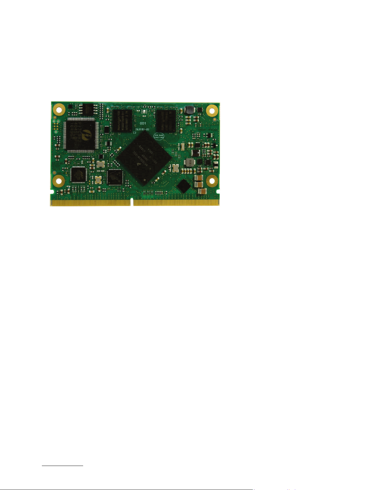
The SMARC-sAMX7 is a SMARC half-size module using the NXPs i.MX7 processor with either single or dual core
ARM. It is designed on the latest SMARC 2.0 specification and supports ARM or x86 architectures. The SMARCsAMX7 is a highly integrated, embedded computer board.
Figure 1: Half-size Card with SMARC interface
2.1. SMARC™ Computer-on-Modules
The SMARC™ standard was developed especially for new modules with ARM- and SoC-processors. Boards with this
interfaces are characterized by the extremely flat form factor. The SMARC or MXM 3.0 connector comes with 314
pins and a construction height of just 4.3 millimeters. The connector is also available in a shock- and vibrationresistant version for rough environmental conditions.
Furthermore, the standard integrates dedicated interfaces for the latest ARM, x86 and SoC processors like LVDS,
24-bit RGB and HDMI support. In addition, dedicated camera interfaces are being incorporated into a COM standard.
OEMs profit from minimized design effort and low Bill of Material (BoM) costs. SMARC™ defines two different
module sizes in order to offer a high level of flexibility regarding different mechanical requirements.
www.kontron.com // 13
Page 14
SMARC-sAMX7 User Guide. Rev. 1.5
Main characteristics of the SMARC-sAMX7 are:
Single/Dual Cortex A7-Core based on NXP’s processor i.MX7 Solo with 800 MHz and 2 W max power or i.MX7
Dual with 1000 MHz and 4 W max power
Up to 2 GB DDR3L memory down
2 to 64 GB eMMC (optionally)
LVDS dual channel graphics
MIPI CSI camera interface
USB 2.0 On the Go (OTG)
5x USB 2.0 Host interface
2x SPI
2x Ethernet (Solo processor 1x Ethernet)
Dual only: 1x PCIe, optional 4x PCIe via bridge
12x GPIOs
4x UART, 1x with 64 B FIFO
2x CAN Bus interface
Support for audio and common features (SPI, I2C)
APPROTECT (security chip) support on request, more information under
https://www.kontron.de/products/solutions/security/approtect.html
2.2. Product Variants and Accessories
Following variants are planned:
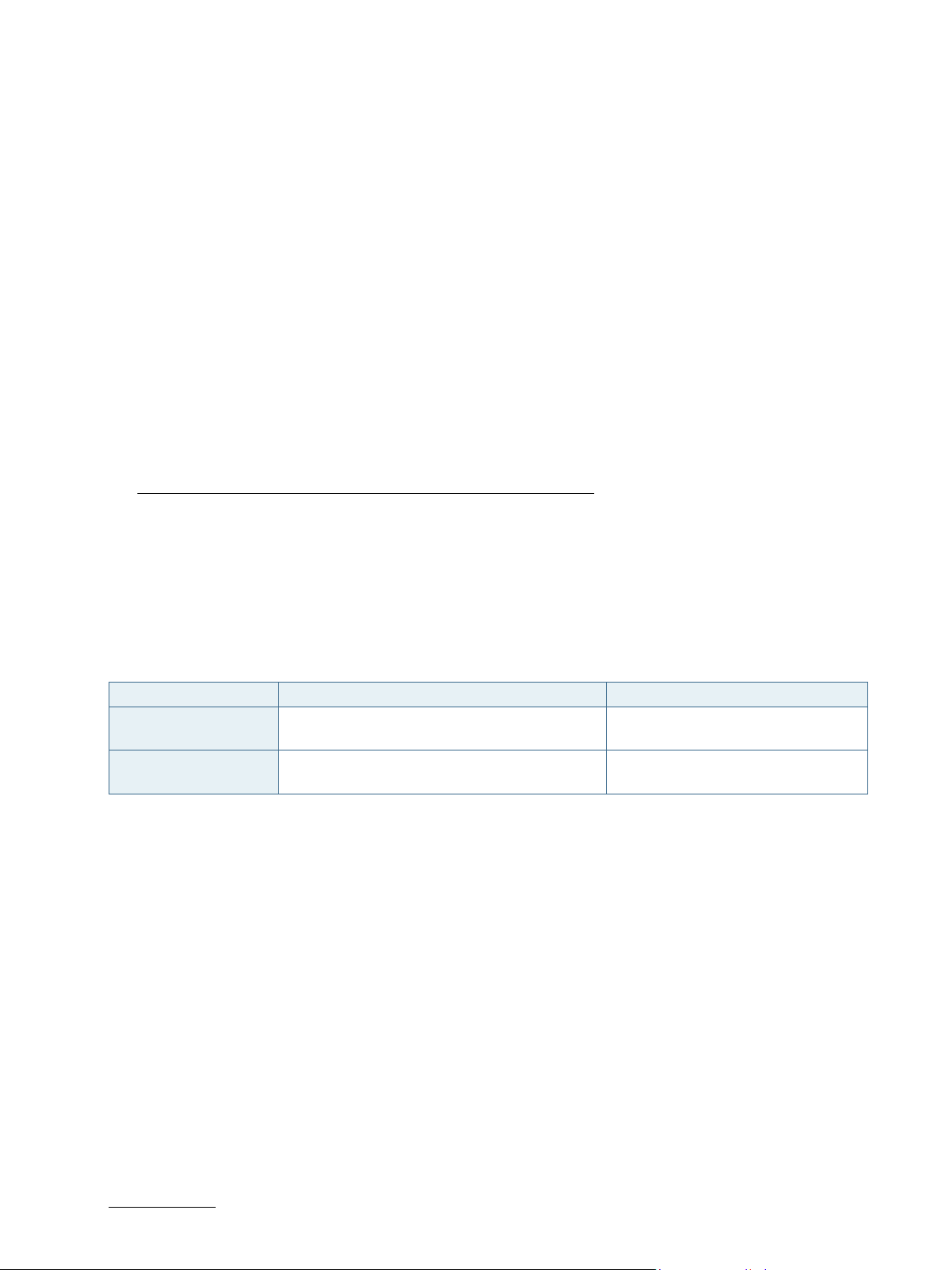
Table 1: Product Variants of SMARC-sAMX7
Board Description Product Number
SMARC-sAMX7 Solo SMARC-sAMX7 Solo with 1 GB DDR3L, 4 G
pseudo Single Level Cell (pSLC) eMMC
SMARC-sAMX7 Dual SMARC-sAMX7 Dual with 2 GB DDR3L, 8 G pSLC
eMMC
Following accessories are available:
SMARC 2.0 Evaluation Carrier
SMARC Starter Kit
51009-0104-08-1
51009-0208-10-2
www.kontron.com // 14
Page 15
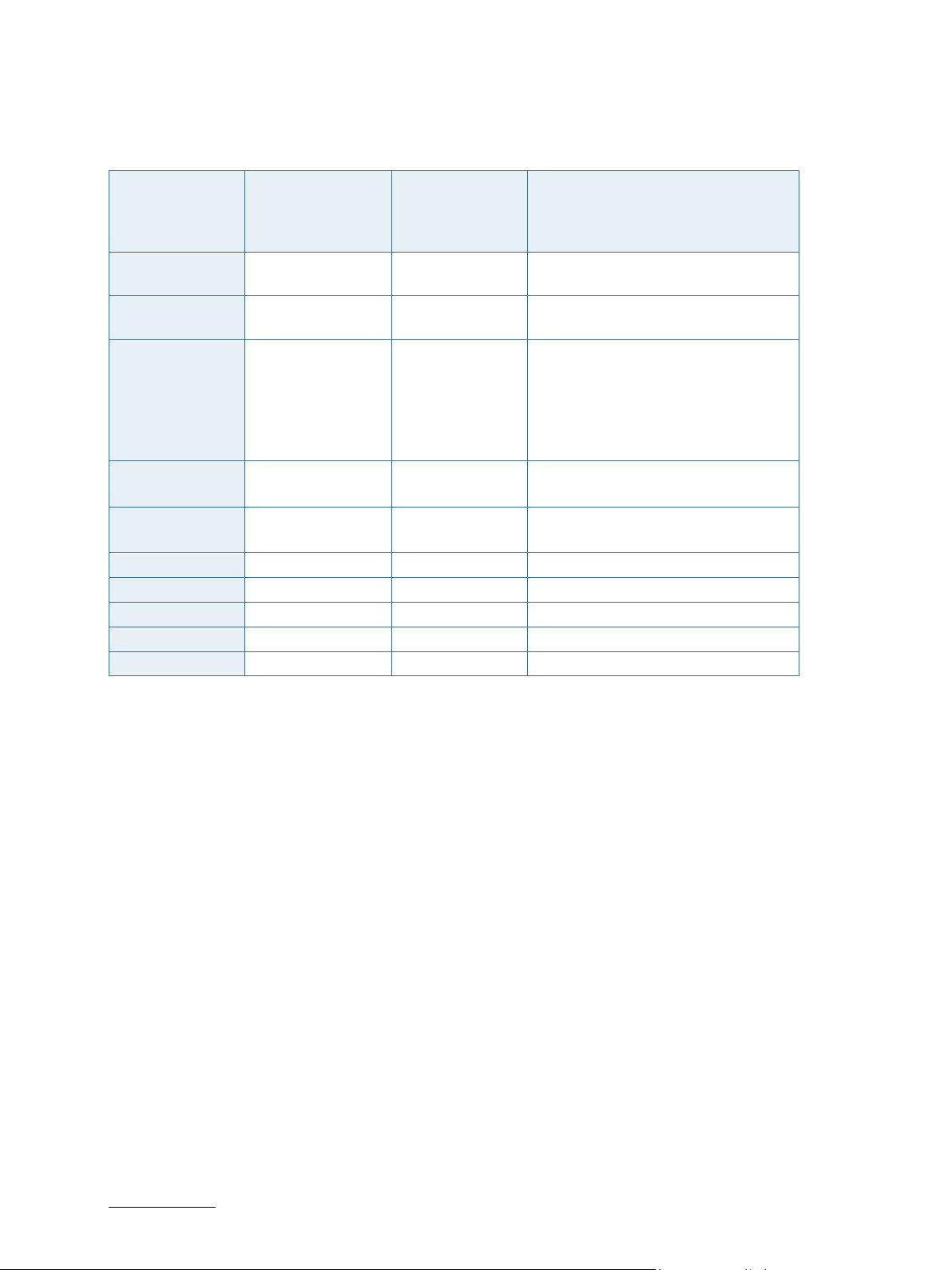
2.3. SMARC-sAMX7 Feature Set
Table 2: SMARC-sAMX7 Feature Set
SMARC-sAMX7 User Guide. Rev. 1.5
SMARC™ Feature
specification
LVDS Display
support
CSI Camera
support
USB Interface 6 x USB 2.0
PCIe Interface 4 3 single core: 0
GbE Interface 1/2 Yes 1 (Solo Proc.)
SDIO Interface 1 Yes
SPI Interface 2 Yes
I2S Interface 2 Yes
I2C Interface 5 4
CAN 2 2
SMARC™
Specification
Maximum Number
Possible
1 1 LVDS dual Channel
2 Yes Quad lane
with 2 x USB 3.0
included
SMARC-sAMX7
Feature support
6x USB 2.0
with APPROTECT
5x
Description
- single core: 1x USB OTG port, 4 USB
host ports (3x with WIBU key
option/APPROTECT)
- dual core: 2x USB OTG ports, 4x USB
host ports (3x with WIBU key
option/APPROTECT)
dual core: 1 or 3
2 (Dual proc.)
www.kontron.com // 15
Page 16
SMARC-sAMX7 User Guide. Rev. 1.5
mm
3/ System Specifications
3.1. Component Main Data
The table below summarizes the features of the motherboard.
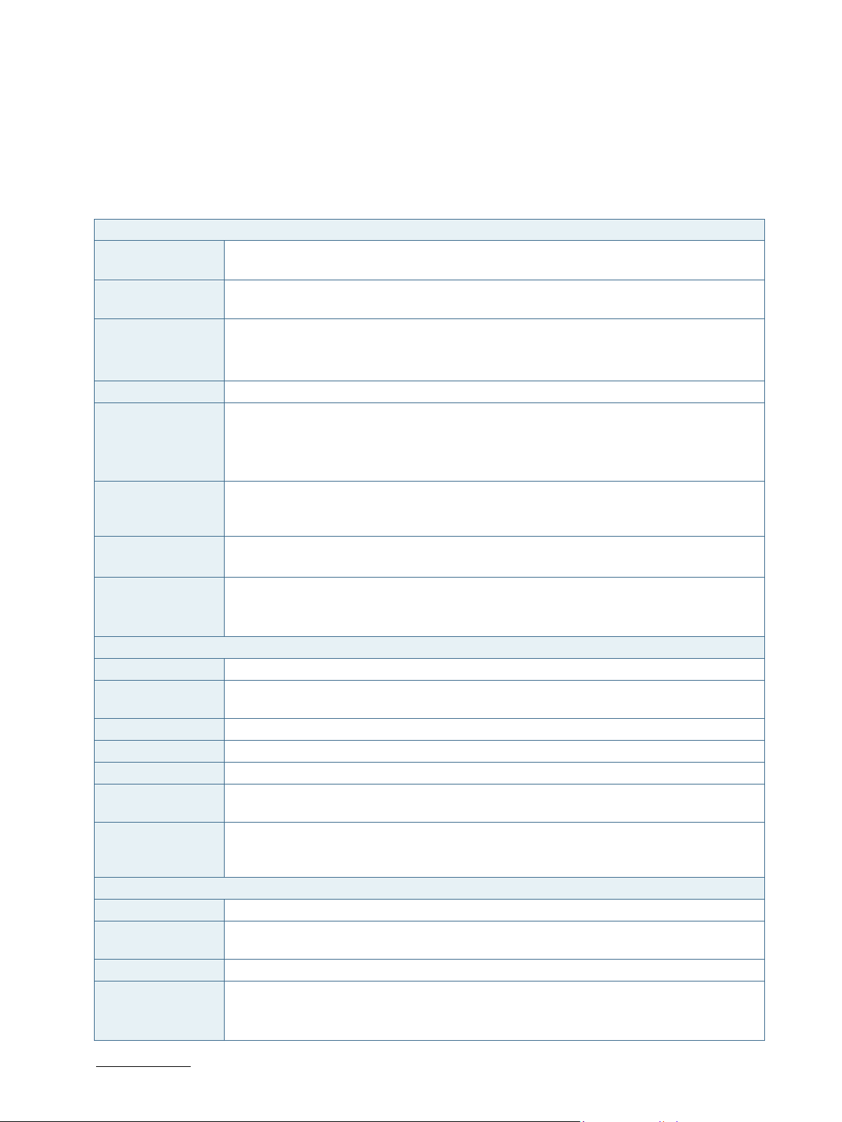
Table 3: Component Main Data
SMARC-sAMX7
Form factor Smart Mobility ARChitecture (SMARC) Hardware with 82 mm x 50 mm, max. thickness
6
Processor Freescale/NXP/Qualcomm’s i.MX7 28nm (Solo and Dual SKUs) with 19mm x 19mm BGA
package in 0.75mm pitch (industrial version)
Memory 533 MHz 32-bit DDR3L
Solo CPU: 1 GB 4x 2 Gbit 256 Mx8
Dual CPU: 2 GB 4x 4 Gbit 512 Mx8
Boot Flash SPI NOR flash
Bootloader/BIOS U-Boot Bootloader, Flash for Bootloader connected on SPI0. Two SPI package sizes are
possible with current layout:
WSON8_5x8 (up to 128 Mbit/16 MB)
WSON8_6x8 (256 Mbit/32 MB)
embedded
Multimedia Card
(eMMC)
EEPROM Type: 24C32, 4k x 8 (32k bit)
Display 18/24-bit LVDS RGB (True Color)
Onboard Controllers
Ethernet Controller 1x GBE PHY 88E1510PB2, second optional PHY only on dual SKU
Watchdog Timer CPU internal watchdog, configurable timeout counter with timeout periods from 0.5 to 128
USB HUB USB HSIC 4 port Hub USB4604
PCI Switch PCIe packet switch PI7C9X2G404SL (optional for Solo SKU)
Display bridge MIPI DSI to LVDS Flatlink SN65DSI84ZQER
Real Time Clock
(RTC)
System
Management
Controller
Storage 2 to 64 GB eMMC 5.0 Flash (option)
H/W Status
Monitor
Security APPROTECT Key optional
Power
management
2 to 32 GB pseudo Single Level Cell (pSLC)
4 to 64 GB MLC (Multi-level Cell)
Connected at I2C_GP bus at address 0x50 (7-bit)
Resolution: up to 1920x1080 Pixel
Single/Dual Channel
seconds
High accuracy (+/-3%), low power, RV-8803
No dedicated System Management Controller on module System settings can be arranged
in U-Boot environment variables
temperature monitoring sensor
Clock Control Module (CCM)
General Power Controller (GPC)
System Reset Controller (SRC)
www.kontron.com // 16
Page 17
SMARC-sAMX7 User Guide. Rev. 1.5
Operating System
Linux Yocto, other Operating Systems only on customer request
Support
Interfaces via Smarc I/O
I2C 4x I2C interfaces which are derived from the SoC, the iMX7 I2C IOs PADs are configured
according the NXP AN5078,
I2C_PM Power Management Support
I2C_GP General Purpose Use
I2C_CAM0 camera support
I2C_LCD Display support
LAN, USB 1x Gb-Ethernet Solo processor, 2x Gb interface with Dual processor,
Solo processor: 1x USB OTG and 4x USB2.0 with High-Speed Inter-Chip (HSIC) hub
Dual processor: 2x USB OTG and 4x USB2.0 with HSIC hub
PCIe solo processor: no PCIe
dual processor: 3x PCIe via PCIe switch, option for 1x PCIe without PCIe switch
Audio 2x Synchronous Audio Interface (SAI)
Display 2x LVDS interfaces with DSI to flatlink LVDS bridge over 2 MIPI DSI lanes with 1000
Mbits/sec per DSI lane
Camera iMX7 display and camera subsystem, MIPI CSI camera interface
SD-Card 1x SDIO
UART 4x UART, one is used for serial console by default
Serial Peripheral
4x SPI
Interface (SPI)
GPIO 12x General Purpose Inputs/Outputs (GPIO)
other Connectivity Keypad, 2x CAN
Power
Consumption Maximum Power consumption of the board is measured to 2 W (Single Core) and 4 W (Dual
Core)
Input Voltage Wide range VCC 3.0 V to 5.25 V
www.kontron.com // 17
Page 18
Table 4: Environmental Conditions
Operating industrial: -20°C to 85°C
relative humidity (non-condensing) 10 % to 93 % at 40°C
Storage commercial grade: -40°C to +85°C
relative humidity (non-condensing) 10 % to 93 % at 40°C
Electromagnetic
CE according to (EMC) Directive 2014/30/EU (EN55032, EN55024)
Compatibility
(EMC) and
Interference (EMI)
Shock according to IEC/EN60068-2-6 and IEC/EN60068-2-27
Vibration according to IEC/EN60068-2-6 and IEC/EN60068-2-27
Electrical Safety CE according to low Voltage Directive 2014/35/EU (EN62368-1)
Component Recognition to UL62368-1
Theoretical MTBF estimated 10 years at 40°C
Restriction of
The product is RoHS II compliant
Hazardous
Substances
(RoHS) II
Compliance
SMARC-sAMX7 User Guide. Rev. 1.5
www.kontron.com // 18
Page 19
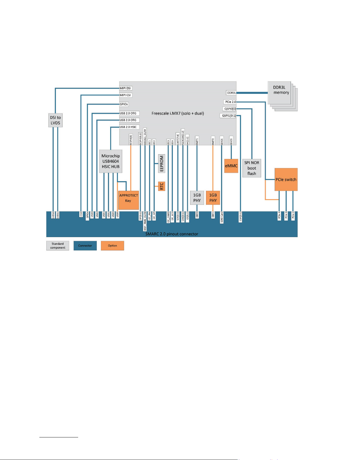
3.2. Functional Block Diagram
The block diagram shows all available interfaces on the sAMX7 module.
Figure 2: Block Diagram
SMARC-sAMX7 User Guide. Rev. 1.5
www.kontron.com // 19
Page 20
SMARC-sAMX7 User Guide. Rev. 1.5
4
2
4/ Board and Connectors
4.1.1. Connectors
Table 5: Connectors of SMARC-sAMX7
Connector Function Remark
SMARC Central Interface Mating connector: SMARC 2.0
(MXM3)
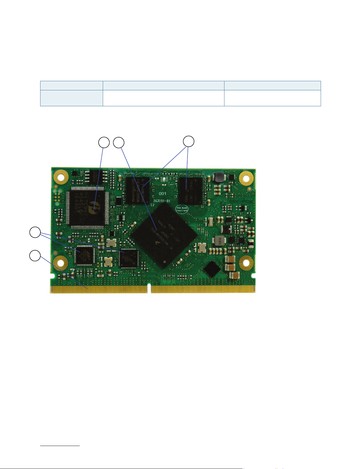
4.2. Mainboard view and I/O locations
Figure 3: Top View
5
1
3
1. PCIe Switch
2. Freescale Processor
3. DDR3L memory 2x
4. SMARC Interface
5. GbE PHYs 2x
www.kontron.com // 20
Page 21
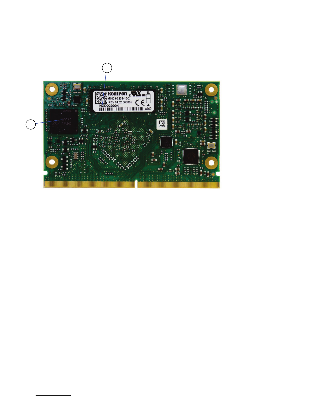
4.3. Bottom Side
Figure 4: Bottom Side from SMARC-sAMX7
6
7
SMARC-sAMX7 User Guide. Rev. 1.5
6. Type Label on DDR3L memory
7. embedded Multimedia Card
(eMMC)
www.kontron.com // 21
Page 22
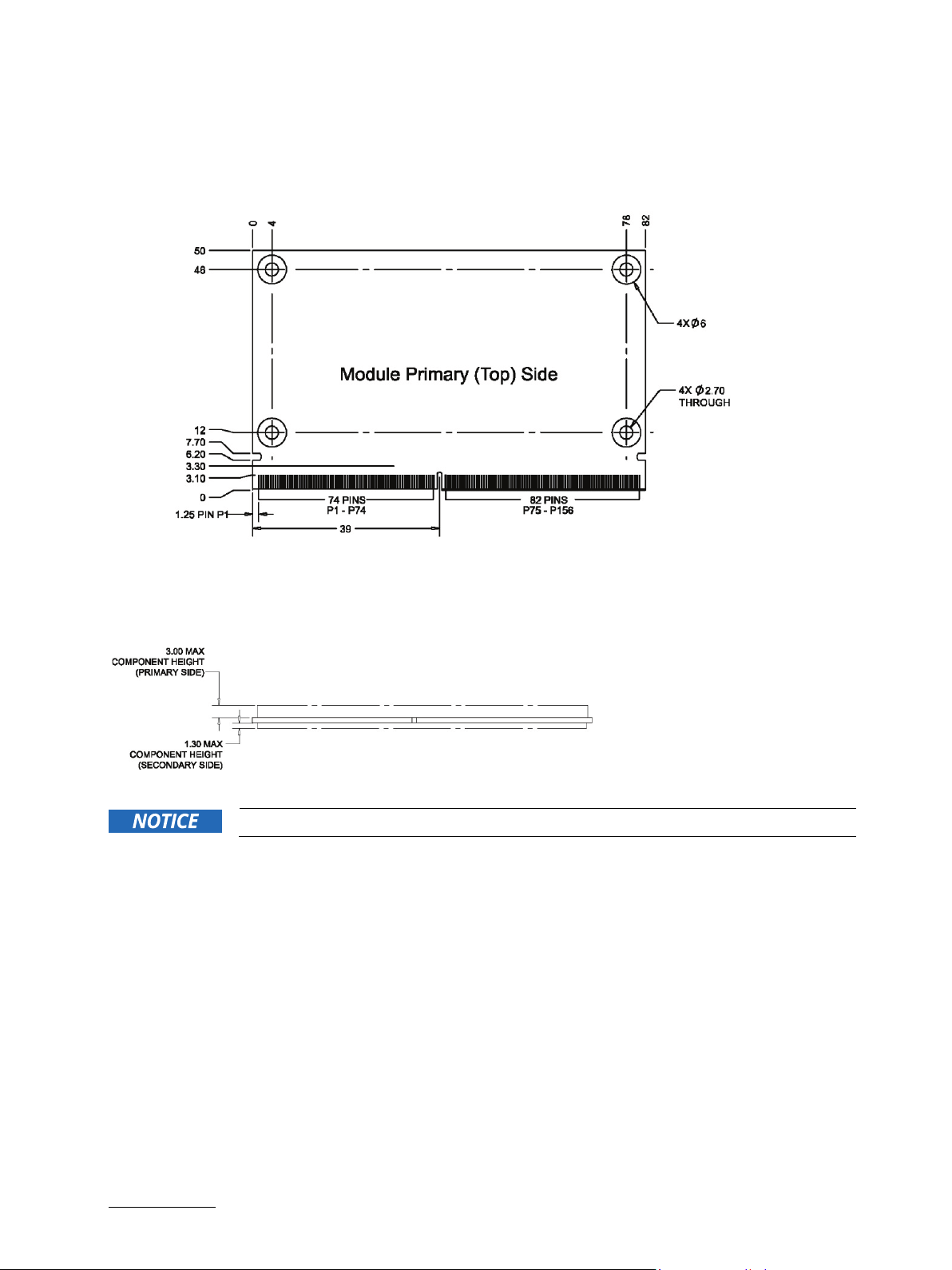
4.4. Mechanical Drawings
Figure 5: Dimensions of SMARC-sAMX7
SMARC-sAMX7 User Guide. Rev. 1.5
Figure 6: Thickness from side view
Heat spreader mech. data is available on customer section
www.kontron.com // 22
Page 23
SMARC-sAMX7 User Guide. Rev. 1.5
5/ Pin Definitions
5.1. Processor Support
Kontron used a Freescale/NXP/Qualcomm’s i.MX7 chip with 28 nm die. There are Solo and Dual SKUs with
19 mm x 19 mm BGA package in 0.75 mm pitch available.
Table 6: Processor Support
Name Speed RAM. Cache TDP/Tj
Solo CPU:
MCIMX7S5EVM08SC
Dual CPU:
MCIMX7D5EVM10SC
5.2. System Memory Support
The memory system has one DDR3L channel. The system supports the following memory features:
32-bit data bus width (4 devices x8 bit)
533 MHz (1066 MT/s) clock (data rate)
0.8 GHz 1 GB 512 KB 2 W/-20°C to
105ºC
1.0 GHz 2 GB 512 KB 4 W/-20°C
to 105ºC
Table 7: DDR3L memory options
512MB
4x1 Gbit density 128Mx8 DDR 3L parts
1 GByte
4x 2 GBit density 256Mx8 DDR3L parts
2 GByte
4x 4 GBit density 512Mx8 DDR3L parts
5.3. SMARC Connector
The SMARC connector has different pins on both sides:
Top side: 74 pins are on the left side, 82 pins on the right side
Bottom side: 75 pins are on the left side, 83 pins on the right side
www.kontron.com // 23
Page 24
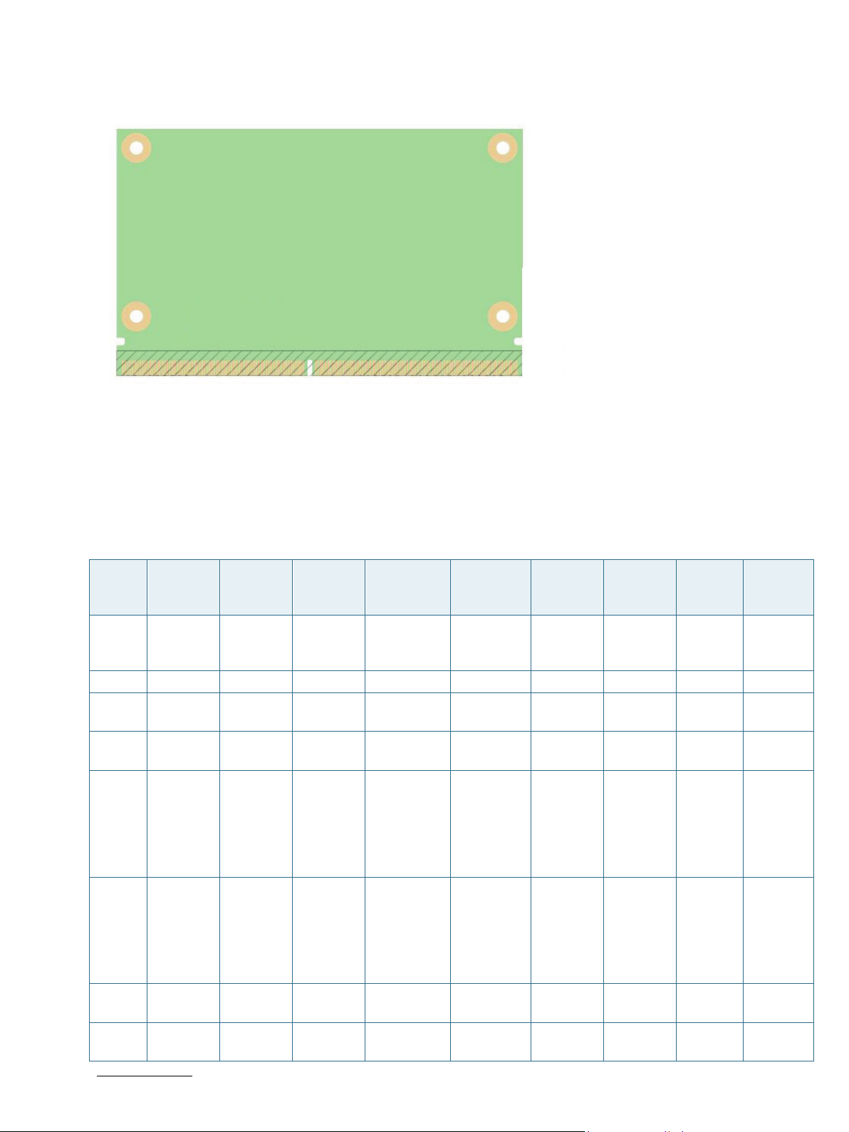
Figure 7: 314-pin SMARC Connector,
5.4. Pinout of SMARC sAMX7 Connector
SMARC-sAMX7 User Guide. Rev. 1.5
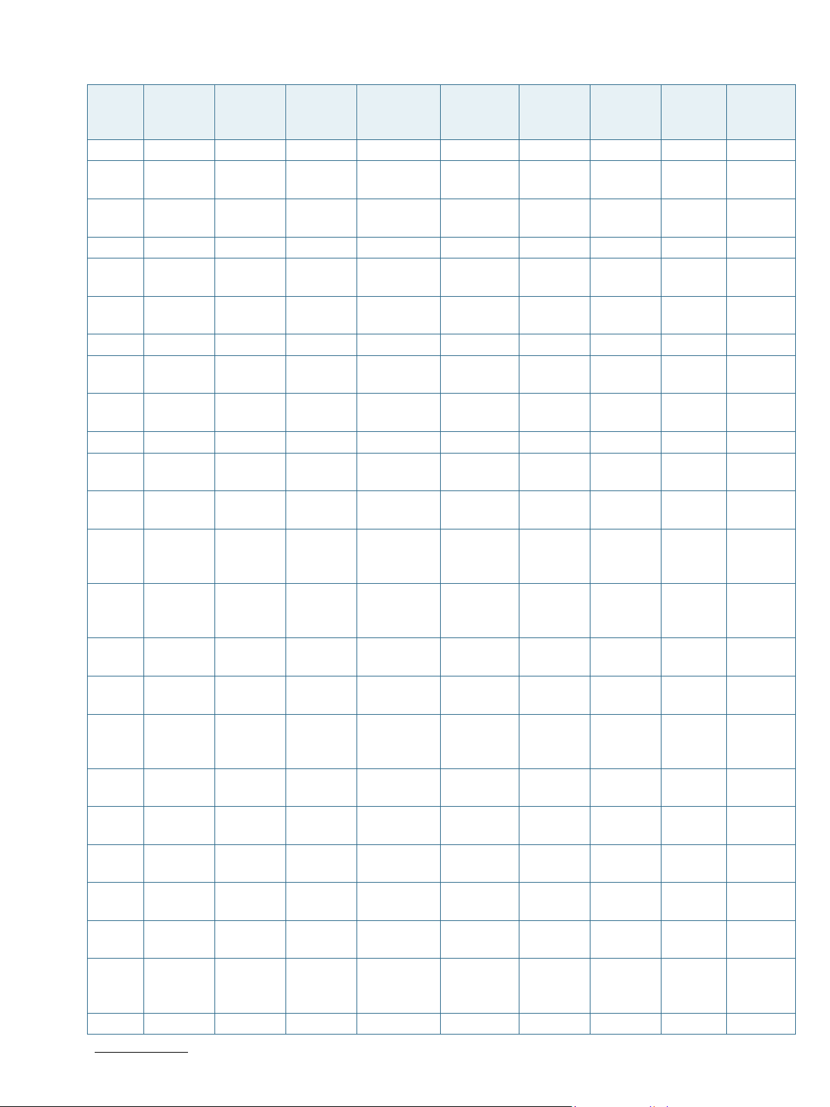
5.4.1. Pinout of SMARC sAMX7 Topside Connector
Table 8: Pinout of SMARC sAMX7 Topside Connector
Pin Signal Module
Direction
P1 SMB_A
LERT_1
V8#
P2 GND - - - - - - - GND
P3 CSI1_CK+ In - LVDS D-
P4 CSI1_CK- In - LVDS D-
P5 GBE1_S
DP
P6 GBE0_
SDP
P7 CSI1_D
0+
P8 CSI1_D
0-
www.kontron.com // 24
In - CMOS
Bi-Dir - GBE MDI iMX7 UART2
Bi-Dir - GBE MDI iMX7 UART3
In - LVDS D-
In - LVDS D-
Module
Termination
Type/Tolerance
1.8V
PHY
PHY
PHY
PHY
Controller
iMX7 EPDC_
- - - -
- - - -
- - - -
- - - -
Control
ler Pin
Name
PWRST
AT
_RXD+
UART2
_TXD
_RTX#
+UART
3_CTS#
Port(i.
MX7
dual)
GPIO2_
IO31
ENET2
_1588_
IN1+EN
ET2_15
88_OU
T1
ENET1_
1588_I
N1+ENE
T1_158
8_OUT1
Port
(i.MX7
Solo)
GPIO2
_IO31
-
ENET1
_1588
_IN1+E
NET1_
1588_
OUT1
Power
Rail
-
-
NVCC_
UART
(1.8V)
NVCC_
UART
(1.8V)
-
-
Page 25
SMARC-sAMX7 User Guide. Rev. 1.5
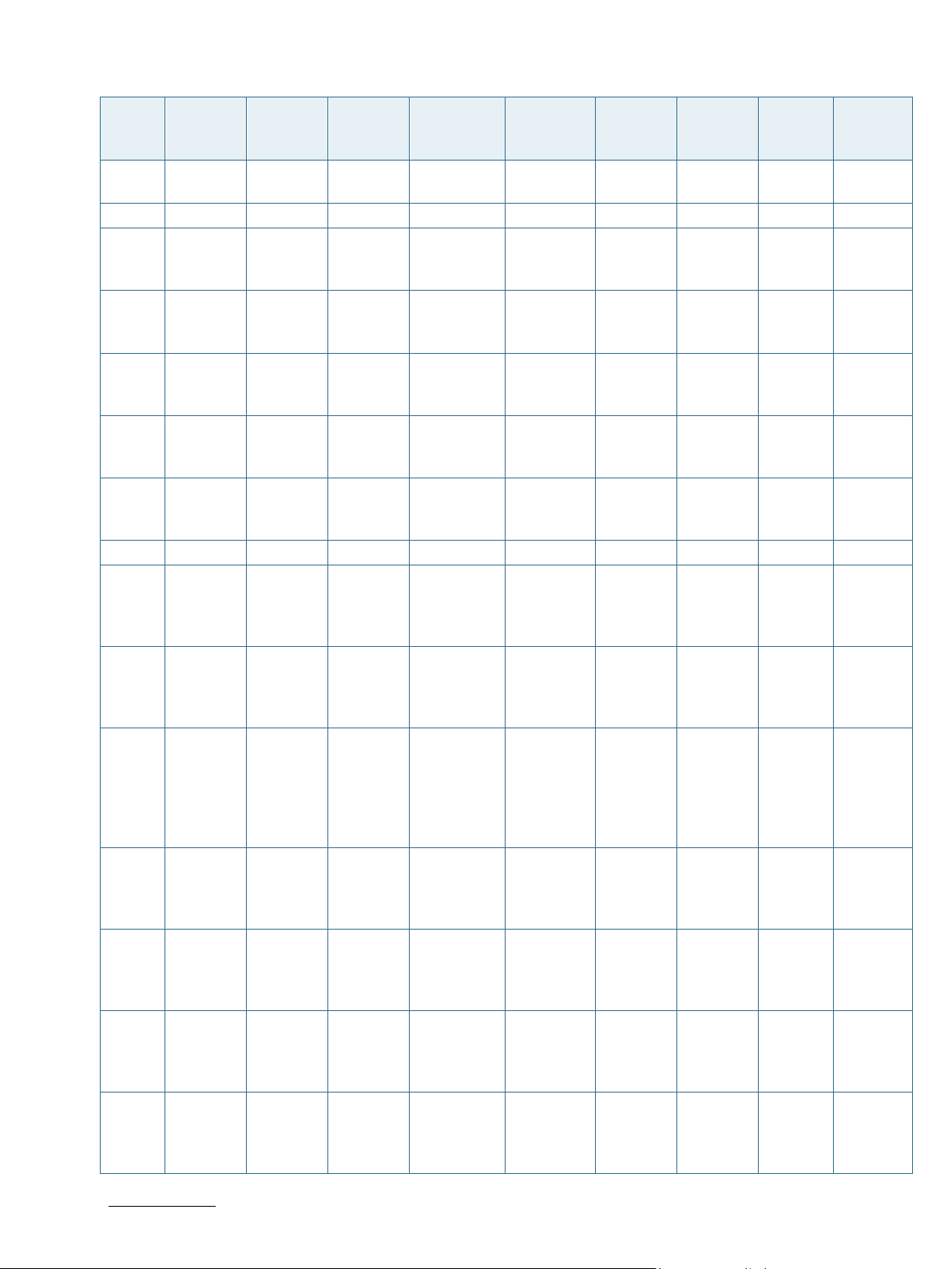
Pin Signal Module
Direction
Module
Termination
Type/Tolerance
Controller
Control
ler Pin
Name
Port(i.
MX7
dual)
Port
(i.MX7
Solo)
Power
Rail
P9 GND - - - - - - - GND
P10 CSI1_D1
+
P11 CSI1_D1
-
In - LVDS D-
PHY
In - LVDS D-
PHY
- - - -
-
- - - -
-
P12 GND - - - - - - - GND
P13 CSI1_D
2+
P14 CSI1_D
2-
In - LVDS D-
PHY
In - LVDS D-
PHY
- - - -
-
- - - -
-
P15 GND - - - - - - - GND
P16 CSI1_D
3+
P17 CSI1_D
3-
IN - LVDS D-
PHY
IN - LVDS D-
PHY
- - - -
-
- - - -
-
P18 GND - - - - - - - GND
P19 GBE0_
MDI3-
P20 GBE0_
MDI3+
P21 GBE0_L
INK100
#
P22 GBE0_L
INK100
0#
P23 GBE0_
MDI2-
P24 GBE0_
MDI2+
P25 GBE0_L
INK_AC
T#
P26 GBE0_
MDI1-
P27 GBE0_
MDI1+
P28 GBE0_
CTREF
P29 GBE0_
MDI0-
P30 GBE0_
MDI0+
P31 SPI0_C
S1#
Bi-Dir - GBE MDI 88E1510
MDI3- RGMII RGMII
PB2
Bi-Dir - GBE MDI 88E1510
MDI3+ RGMII RGMII
PB2
Out/OD - CMOS
3.3V
Out/OD - CMOS
3.3V
Bi-Dir - GBE MDI 88E1510
88E1510
PB2
88E1510
PB2
LED_1 RGMII RGMII
LED_0 RGMII RGMII
MDI2- RGMII RGMII
PB2
Bi-Dir - GBE MDI 88E1510
MDI2+ RGMII RGMII
PB2
Out/OD - CMOS
3.3V
Bi-Dir - GBE MDI 88E1510
88E1510
PB2
LED_2/
RGMII RGMII
INT#
MDI1- RGMII RGMII
PB2
Bi-Dir - GBE MDI 88E1510
MDI1+ RGMII RGMII
PB2
Out - - - - - -
Bi-Dir - GBE MDI 88E1510
MDI0- RGMII RGMII
PB2
Bi-Dir - GBE MDI 88E1510
MDI0+ RGMII RGMII
PB2
Out - CMOS
1.8V
iMX7 SD2_CS# ECSPI3
_SS2
ECSPI
3_SS2
-
-
-
-
-
-
-
-
-
-
-
-
NVCC_
SD2
(1.8V)
P32 GND - - - - - - - GND
www.kontron.com // 25
Page 26

SMARC-sAMX7 User Guide. Rev. 1.5
Pin Signal Module
Direction
P33 SDIO_
In PU-10k CMOS
WP
Module
Termination
Type/Tolerance
3.3V
Controller
Control
ler Pin
Name
iMX7 SD1_W
P
Port(i.
MX7
dual)
SD1_W
P
Port
(i.MX7
Solo)
SD1_
WP
Power
Rail
NVCC_
SD1
(3.3V)
P34 SDIO_C
MD
Bi-Dir CMOS
3.3V
iMX7 SD1_C
MD
SD1_C
MD
SD1_C
MD
NVCC_
SD1
(3.3V)
P35 SDIO_C
D#
In PU-10k CMOS
3.3V
iMX7 SD1_CD
#
SD1_CD
#
SD1_C
D#
NVCC_
SD1
(3.3V)
P36 SDIO_C
K
Out - CMOS
3.3V
iMX7 SD1_CL
K
SD1_CL
K
SD1_C
LK
NVCC_
SD1
(3.3V)
P37 SDIO_P
WR_EN
Out - CMOS
3.3V
iMX7 SD1_RE
SET#
GPIO5_I
O02
GPIO5
_IO02
NVCC_
SD1
(3.3V)
P38 GND - - - - - - - GND
P39 SDIO_D
0
Bi-Dir - CMOS
3.3V
iMX7 SD1_DA
TA0
SD1_DA
TA0
SD1_D
ATA0
NVCC_
SD1
(3.3V)
P40 SDIO_D
1
Bi-Dir - CMOS
3.3V
iMX7 SD1_DA
TA1
SD1_DA
TA1
SD1_D
ATA1
NVCC_
SD1
(3.3V)
P41 SDIO_D
2
Bi-Dir - CMOS
3.3V
iMX7 SD1_DA
TA2
SD1_DA
TA2
SD1_D
ATA2
NVCC_
SD1
(3.3V)
P42 SDIO_D
3
Bi-Dir - CMOS
3.3V
iMX7 SD1_DA
TA3
SD1_DA
TA3
SD1_D
ATA3
NVCC_
SD1
(3.3V)
P43 SPI0_C
S0#
P44 SPI0_C
K
P45 SPI0_DIN In CMOS
P46 SPI0_D
O
Out - CMOS
1.8V
Out - CMOS
1.8V
1.8V
Out CMOS
1.8V
iMX7 SAI2_T
XD
iMX7 SAI2_R
XD
ECSPI3
_SS00
ECSPI3
_SCLK
iMX7 I2C1_SCL ECSPI3
_MISO
iMX7 I2C1_S
DA
ECSPI3
_MOSI
ECSPI
3_SS0
0
ECSPI
3_SCL
K
ECSPI
3_MIS
O
ECSPI
3_MO
SI
NVCC_
SAI
(1.8V)
NVCC_
SAI
(1.8V)
NVCC_
SPI
(1.8V)
NVCC_
SPI
(1.8V)
P47 GND - - - - - - - GND
P48 SATA_T
X+
P49 SATA_T
X-
Out - SATA - - - -
-
Out - SATA - - - -
-
P50 GND - - - - - - - GND
P51 SATA_
RX+
In - SATA - - - -
-
www.kontron.com // 26
Page 27
SMARC-sAMX7 User Guide. Rev. 1.5
Pin Signal Module
Direction
P52 SATA_
In - SATA - - - -
RX-
Module
Termination
Type/Tolerance
Controller
Control
ler Pin
Name
Port(i.
MX7
dual)
Port
(i.MX7
Solo)
Power
Rail
-
P53 GND - - - - - - - GND
P54 ESPI_C
S0#
P55 ESPI_C
S1#
P56 ESPI_C
K
Out - CMOS
1.8V
Out - CMOS
1.8V
Out - CMOS
1.8V
iMX7 EPDC_
D14
iMX7 EPDC_
D15
iMX7 EPDC_
D13
QSPIB_
SS[0]#
QSPIB_
SS[1]#
QSPIB_
SCLK
QSPIB
_SS[0]
#
QSPIB
_SS[1]
#
QSPIB
_SCLK
NVCC_
EPDC1
(1.8V)
NVCC_
EPDC1
(1.8V)
NVCC_
EPDC1
(1.8V)
P57 ESPI_IO
_0
In - CMOS
1.8V
iMX7 EPDC_
D8
QSPIB_
DA0
QSPIB
_DA0
NVCC_
EPDC1
(1.8V)
P58 ESPI_IO
_1
Out - CMOS
1.8V
iMX7 EPDC_
D9
QSPIB_
DA1
QSPIB
_DA1
NVCC_
EPDC1
(1.8V)
P59 GND - - - - - - - GND
P60 USB0+ Bi-Dir - USB iMX7 USB_O
TG1_DP
USB_O
TG1_DP
USB_
OTG1_
DP
USB_O
TG1_V
DDA
(3.3V)
P61 USB0- Bi-Dir - USB iMX7 USB_O
TG1_D
N
USB_O
TG1_D
N
USB_
OTG1_
DN
USB_O
TG1_V
DDA
(3.3V)
P62 USB0_
EN_OC
#
P63 USB0_
VBUS_
DET
Bi-Dir
OD
PU4k75
CMOS
3.3V
In - CMOS
3.3V
iMX7 GPIO1_I
O04+G
PIO1_IO
05
iMX7 USB_O
TG1_VB
US
USB_O
TG1_OC
+USB_
OTG2_
PWR
USB_O
TG1_VB
US
USB_
OTG1_
OC+US
B_OT
G2_P
WR
USB_
OTG1_
VBUS
USB_O
TG1_V
DDA
(3.3V)
USB_O
TG1_V
DDA
(3.3V)
P64 USB0_
OTG_ID
In - CMOS
3.3V
iMX7 USB_O
TG1_ID
USB_O
TG1_ID
USB_
OTG1_
ID
USB_O
TG1_V
DDA
(3.3V)
P65 USB1+ Bi-Dir - USB USB460
4
USBDN
1_DP/P
HSIC HSIC
RT_DIS
P66 USB1- Bi-Dir - USB USB460
4
_P1
USBDN
1_DM/
HSIC HSIC
-
PRT_DI
S_M1
-
www.kontron.com // 27
Page 28

SMARC-sAMX7 User Guide. Rev. 1.5
Pin Signal Module
Direction
P67 USB1_E
N_OC#
Bi-Dir
OD
Module
Termination
PU4k75
Type/Tolerance
CMOS
3.3V
Controller
USB460
4
Control
ler Pin
Name
PRTPW
R1/PRT
CTL1
Port(i.
MX7
dual)
Port
(i.MX7
Solo)
HSIC HSIC
Power
Rail
-
P68 GND - - - - - - - GND
P69 USB2+ Bi-Dir - USB USB460
4
USBDN
2_DP/P
HSIC HSIC
RT_DIS
P70 USB2- Bi-Dir - USB USB460
4
_P2
USBDN
2_DM/
HSIC HSIC
-
PRT_DI
P71 USB2_
EN_OC
#
Bi-Dir
OD
PU4k75
CMOS
3.3V
USB460
4
S_M2
PRTPW
R2/PRT
CTL2
HSIC HSIC
-
-
P72 RSVD - - - - - - - -
P73 RSVD - - - - - - - -
P74 USB3_
EN_OC
#
Bi-Dir
OD
PU4k75
CMOS
3.3V
iMX7 USB_O
TG3_ID
USB_O
TG3_ID
- USB_O
TG2_V
DDA
(3.3V)
P75 PCIE_A
_RST#
P76 USB4_
EN_OC
#
Out PU-
4k75
Bi-Dir
OD
PU4k75
CMOS
3.3V
CMOS
3.3V
iMX7/PI7
C9X2G40
4SL
LCD_D
ATA_11
/DWNR
ST_1#
iMX7 PRTPW
R3/PRT
CTL3
GPIO3_I
-
O16
HSIC HSIC
NVCC_
LCD
(1.8V)
-
P77 RSVD - - - - - - - -
P78 RSVD - - - - - - - -
P79 GND - - - - - - - GND
P80 PCIE_C
_REFCK
+
P81 PCIE_C
_REFCK
-
Out Seriell-
100n
Out Seriell-
100n
LVDS
PCIe
LVDS
PCIe
PI7C9X2
G404SL
PI7C9X2
G404SL
REFCLK
O_3+
REFCLK
O_3-
PCIe -
-
PCIe -
-
P82 GND - - - - - - - GND
P83 PCIE_A
_REFCK
+
P84 PCIE_A
_REFCK
-
Out Seriell-
100n
Out Seriell-
100n
LVDS
PCIe
LVDS
PCIe
PI7C9X2
G404SL
PI7C9X2
G404SL
REFCLK
O_1+
REFCLK
O_1-
PCIe -
-
PCIe -
-
P85 GND - - - - - - - GND
P86 PCIE_A
_RX+
In Serial-
0R
LVDS
PCIe
PI7C9X2
G404SL
PER_1+ PCIe -
-
www.kontron.com // 28
Page 29

SMARC-sAMX7 User Guide. Rev. 1.5
Pin Signal Module
Direction
P87 PCIE_A
In Serial-
_RX-
Module
Termination
0R
Type/Tolerance
LVDS
PCIe
Controller
PI7C9X2
G404SL
Control
ler Pin
Name
Port(i.
MX7
dual)
PER_1- PCIe -
Port
(i.MX7
Solo)
Power
Rail
-
P88 GND - - - - - - - GND
P89 PCIE_A
_TX+
P90 PCIE_A
_TX-
Out Seriell-
100n
Out Seriell-
100n
LVDS
PCIe
LVDS
PCIe
PI7C9X2
G404SL
PI7C9X2
G404SL
PET_1+ PCIe -
-
PET_1- PCIe -
-
P91 GND - - - - - - - GND
P92 HDMI_
Out - TMDS - - - D2+/D
P1_LAN
E0+
P93 HDMI_
Out - TMDS - - - -
-
D2/DP1_L
ANE0-
-
P94 GND - - - - - - - GND
P95 HDMI_
Out - TMDS - - - D1+
/DP1_L
ANE1+
P96 HDMI_
Out - TMDS - - - -
-
D1/DP1_L
ANE1-
-
P97 GND - - - - - - - GND
P98 HDMI_
Out - TMDS - - - D0+/D
P1_LAN
E2+
P99 HDMI_
Out - TMDS - - - -
-
D0/DP1_L
ANE2-
-
P100 GND - - - - - - - GND
P101 HDMI_
Out - TMDS - - - CK+
/DP1_L
ANE3+
P102 HDMI_
Out - TMDS - - - -
-
CK/DP1_L
ANE3-
-
P103 GND - - - - - - - GND
P104 HDMI_
HPD/D
P1_HPD
In - CMOS
1.8V
- - - -
-
www.kontron.com // 29
Page 30

SMARC-sAMX7 User Guide. Rev. 1.5
Pin Signal Module
Directi-
on
P105 HDMI_
Out - CMOS
CTRL_C
Module
Termination
Type/Tolerance
1.8V
Controller
Control
ler Pin
Name
Port(i.
MX7
dual)
- - - -
Port
(i.MX7
Solo)
Power
Rail
K/DP1_
AUX+
P106 HDMI_
CTRL_D
Bi-Dir - CMOS
1.8V
- - - -
-
AT/DPS
1_AUX-
P107 DP1_AU
X_SEL
P108 GPIO0/
CAM0_
PWR#
P109 GPIO1/
CAM1_
PWR#
P110 GPIO2/
CAM0_
RST#
P111 GPIO3/
CAM1_
RST#
P112 GPIO4/
HDA_R
ST#
P113 GPIO5/
PWM_
OUT
P114 GPIO6/
TACHIN
In - CMOS
1.8V
Bi-Dir PU-
470k
Bi-Dir PU-
470k
Bi-Dir PU-
470k
Bi-Dir PU-
470k
Bi-Dir PU-
470k
Bi-Dir PU-
470k
Bi-Dir PU-
470k
CMOS
1.8V
CMOS
1.8V
CMOS
1.8V
CMOS
1.8V
CMOS
1.8V
CMOS
1.8V
CMOS
1.8V
- - - -
iMX7 LCD_D
ATA0
iMX7 LCD_D
ATA1
iMX7 LCD_D
ATA2
iMX7 LCD_D
ATA3
iMX7 LCD_D
ATA4
iMX7 GPIO1_I
O08
iMX7 LCD_D
ATA5
GPIO3_I
O05
GPIO3_I
O06
GPIO3_I
O07
GPIO3_I
O08
GPIO3_I
O09
GPIO1_I
O08
GPIO3_I
O10
GPIO3
_IO05
GPIO3
_IO06
GPIO3
_IO07
GPIO3
_IO08
GPIO3
_IO09
GPIO1
_IO08
GPIO3
_IO10
-
-
NVCC_
LCD
(1.8V)
NVCC_
LCD
(1.8V)
NVCC_
LCD
(1.8V)
NVCC_
LCD
(1.8V)
NVCC_
LCD
(1.8V)
NVCC_
GPIO1
(3.3V)
NVCC_
LCD
(1.8V)
P115 GPIO7 Bi-Dir PU-
470k
CMOS
1.8V
iMX7 LCD_D
ATA6
GPIO3_I
O11
GPIO3
_IO11
NVCC_
LCD
(1.8V)
P116 GPIO8 Bi-Dir PU-
470k
CMOS
1.8V
iMX7 LCD_D
ATA7
GPIO3_I
O12
GPIO3
_IO12
NVCC_
LCD
(1.8V)
P117 GPIO9 Bi-Dir PU-
470k
CMOS
1.8V
iMX7 UART3
_RXD
GPIO4_
IO04
GPIO4
_IO04
NVCC_
UART
(1.8V)
P118 GPIO10 Bi-Dir PU-
470k
CMOS
1.8V
iMX7 UART3
_TXD
GPIO4_
IO05
GPIO4
_IO05
NVCC_
UART
(1.8V)
P119 GPIO11 Bi-Dir PU-
470k
CMOS
1.8V
iMX7 LCD_D
ATA9
GPIO3_I
O24
GPIO3
_IO24
NVCC_
LCD
(1.8V)
P120 GND - - - - - - - GND
www.kontron.com // 30
Page 31

SMARC-sAMX7 User Guide. Rev. 1.5
Pin Signal Module
Directi-
on
P121 I2C_PM
Bi-Dir PU-2k2 CMOS
_CK
Module
Termination
Type/Tolerance
1.8V
Controller
Control
ler Pin
Name
iMX7 I2C3_S
CL
Port(i.
MX7
dual)
I2C3_S
CL
Port
(i.MX7
Solo)
I2C3_
SCL
Power
Rail
NVCC_I
2C
(1.8V)
P122 I2C_PM
_DAT
Bi-Dir PU-2k2 CMOS
1.8V
iMX7 I2C3_S
DA
I2C3_S
DA
I2C3_
SDA
NVCC_I
2C
(1.8V)
P123 BOOT_
SEL0#
In PU-
4k75
CMOS
1.8V
iMX7 LCD_D
ATA19
GPIO3_I
O24
GPIO3
_IO24
NVCC_
LCD
(1.8V)
P124 BOOT_
SEL1#
In PU-
4k75
CMOS
1.8V
iMX7 LCD_D
ATA20
GPIO3_I
O25
GPIO3
_IO25
NVCC_
LCD
(1.8V)
P125 BOOT_
SEL2#
In PU-
4k75
CMOS
1.8V
iMX7 LCD_D
ATA21
GPIO3_I
O26
GPIO3
_IO26
NVCC_
LCD
(1.8V)
P126 RESET_
OUT#
P127 RESET_
IN#
P128 POWER
_BTN#
P129 SER0_TX Out - CMOS
Out -
OD
PU4k75
In PU-
4k75 +
Buffer
In PU-
825R +
FET
CMOS
1.8V
CMOS
1.8V
CMOS
1.8V
1.8V
i.MX7 EPDC_
PWRCO
M
GPIO2_
IO30
GPIO2
_IO30
NVCC_
EPDC1
(1.8V)
i.MX7 POR# POR# POR# NVCC_
GPIO1
(3.3V)
i.MX7 ONOFF
/RESET
#
iMX7 ECSPI1_
SCLK
ONOFF
/RESET
#
UART6
_RXD
ONOF
F/RES
ET#
UART6
_RXD
VDD_S
NVS_I
N (3V)
NVCC_
SPI
(1.8V)
P130 SER0_RX In - CMOS
1.8V
iMX7 ECSPI1_
MOSI
UART6
_TXD
UART6
_TXD
NVCC_
SPI
(1.8V)
P131 SER0_R
TS#
Out - CMOS
1.8V
iMX7 ECSPI1_
MISO
UART6RTS#
UART6
-RTS#
NVCC_
SPI
(1.8V)
P132 SER0_C
TS#
In - CMOS
1.8V
iMX7 ECSPI1_
SS0
UART6
_CTS#
UART6
_CTS#
NVCC_
SPI
(1.8V)
P133 GND - - - - - - - GND
P134 SER1_T
X
P135 SER1_R
X
Out - CMOS
1.8V
In - CMOS
1.8V
iMX7 SAI2_T
XFS
iMX7 SAI2_T
XC
UART4
_RXD
UART4
_TXD
UART
4_RX
D
UART
4_TXD
NVCC_
SAI
(1.8V)
NVCC_
SAI
(1.8V)
P136 SER2_T
X
Out - CMOS
1.8V
iMX7 ECSPI2
_SCLK
UART7
_RXD
UART7
_RXD
NVCC_
SPI
(1.8V)
P137 SER2_RX In - CMOS
1.8V
iMX7 ECSPI2
_MOSI
UART7
_TXD
UART7
_TXD
NVCC_
SPI
(1.8V)
www.kontron.com // 31
Page 32
SMARC-sAMX7 User Guide. Rev. 1.5
Pin Signal Module
Directi-
on
P138 SER2_R
Out - CMOS
TS#
Module
Termination
Type/Tolerance
1.8V
Controller
Control
ler Pin
Name
iMX7 ECSPI2
_MISO
Port(i.
MX7
dual)
UART7
_RTS#
Port
(i.MX7
Solo)
UART7
_RTS#
Power
Rail
NVCC_
SPI
(1.8V)
P139 SER2_C
TS#
In - CMOS
1.8V
iMX7 ECSPI2
_MOSI
UART7
_CTS#
UART7
_CTS#
NVCC_
SPI
(1.8V)
P140 SER3_T
X
Out - CMOS
1.8V
iMX7 I2C4_S
CL
UART5
_RXD
UART5
_RXD
NVCC_I
2C
(1.8V)
P141 SER3_RX In - CMOS
1.8V
iMX7 I2C4_S
DA
UART5
_TXD
UART5
_TXD
NVCC_I
2C
(1.8V)
P142 GND - - - - GND
P143 CAN0_
TX
Out - CMOS
1.8V
iMX7 GPIO1_I
O13
CAN1_T
X
CAN1_
TX
NVCC_
GPIO2
(1.8V)
P144 CAN0_
RX
In - CMOS
1.8V
iMX7 GPIO1_I
O12
CAN1_RX CAN1_
RX
NVCC_
GPIO2
(1.8V)
P145 CAN1_T
X
Out - CMOS
1.8V
iMX7 GPIO1_I
O15
CAN2_
TX
CAN2_
TX
NVCC_
GPIO2
(1.8V)
P146 CAN1_R
X
In - CMOS
1.8V
iMX7 GPIO1_I
O14
CAN2_
RX
CAN2_
RX
NVCC_
GPIO2
(1.8V)
P147 VDD_IN PWR - - - - - - 3.0V -
5.25V
P148 VDD_IN PWR - - - - - - 3.0V -
5.25V
P149 VDD_IN PWR - - - - - - 3.0V -
5.25V
P150 VDD_IN PWR - - - - - - 3.0V -
5.25V
P151 VDD_IN PWR - - - - - - 3.0V -
5.25V
P152 VDD_IN PWR - - - - - - 3.0V -
5.25V
P153 VDD_IN PWR - - - - - - 3.0V -
5.25V
P154 VDD_IN PWR - - - - - - 3.0V -
5.25V
P155 VDD_IN PWR - - - - - - 3.0V -
5.25V
www.kontron.com // 32
Page 33
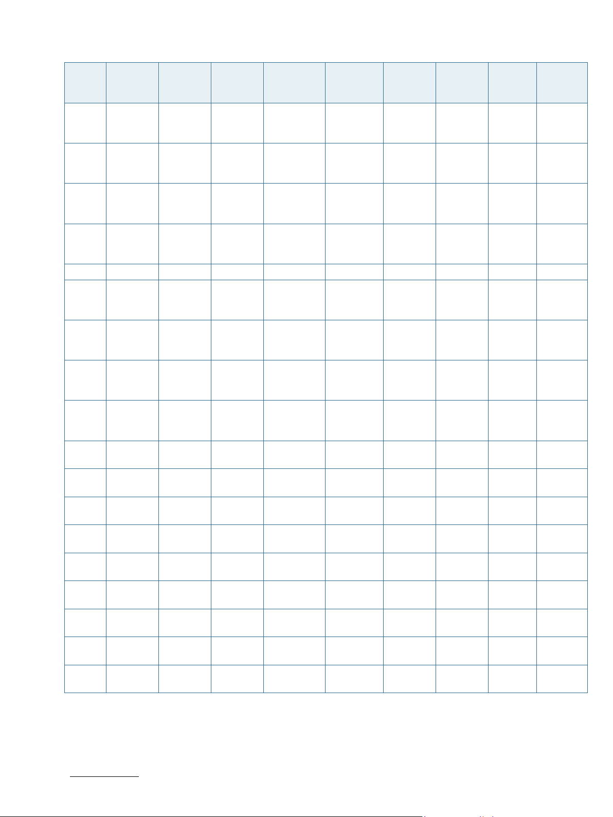
5.4.2. Pinout of SMARC sAMX7 Bottom Side Connector
Table 9: Pinout of SMARC sAMX7 Bottom Side Connector
SMARC-sAMX7 User Guide. Rev. 1.5
Pin Signal Module
Directi-
on
CSI1_T
X+/I2C
_CAM1
S1
S2
S3 GND - - - - - - - GND
S4 RSVD - - - - - - - -
S5
S6
S7
S8
S9
S10 GND - - - - -
S11
S12
S13 GND - - - - - - - GND
S14
www.kontron.com // 33
_CK In -
CSI1_T
X/I2C_C
AM1_D
AT In -
CSI0_T
X/I2C_C
AM0_C
K
CAM_M
CK Out
CSI0_T
X+/I2C
_CAM0
_DAT Bi-Dir
CSI0_C
K+ In -
CSI0_C
K-
CSI0_R
X0+ In -
CSI0_R
X0- In -
CSI0_R
X1+
Out
In -
In -
Module
Termination
PU2k21
Ser10R
PU2k21
Type/Tolerance
TMDS/C
MOS 1.8V - - - - -
TMDS/C
MOS 1.8V - - - - -
TMDS/C
MOS 1.8V
CMOS
1.8V iMX7
TMDS/C
MOS 1.8V iMX7
LVDS DPHY iMX7
LVDS DPHY
LVDS DPHY iMX7
LVDS DPHY iMX7
LVDS DPHY
Controller
iMX7
iMX7
iMX7
Controller Pin
Name
LCD_DA
TA22
CCM_CL
K1_P
LCD_DA
TA23
MIPI_CSI
_CLK_P
MIPI_CSI
_CLK_N
MIPI_CSI
_D0_P
MIPI_CSI
_D0_N
MIPI_CSI
_D1_P
Port(i.
MX7
dual)
I2C4_S
CL
CCM_C
LK1_P
I2C4_S
CL
MIPI_C
SI_CLK
_P
MIPI_C
SI_CLK
_N
MIPI_C
SI_D0_
P
MIPI_C
SI_D0_
N
MIPI_C
SI_D1_
P
Port
(i.MX7
Solo)
I2C4_
SCL
CCM_
CLK1_
P
I2C4_
SCL
MIPI_
CSI_CL
K_P
MIPI_
CSI_CL
K_N
- GND
MIPI_
CSI_D
0_P
MIPI_
CSI_D
0_N
MIPI_
CSI_D1
_P
Power
Rail
NVCC_
EPDC1
(1.8V)
VDDA_
1P8
(1.8V)
NVCC_
EPDC1
(1.8V)
MIPI_V
DDA_1
P8
(1.8V)
MIPI_V
DDA_1
P8
(1.8V)
MIPI_V
DDA_1
P8
(1.8V)
MIPI_V
DDA_1
P8
(1.8V)
MIPI_V
DDA_1
P8
(1.8V)
MIPI_V
Page 34
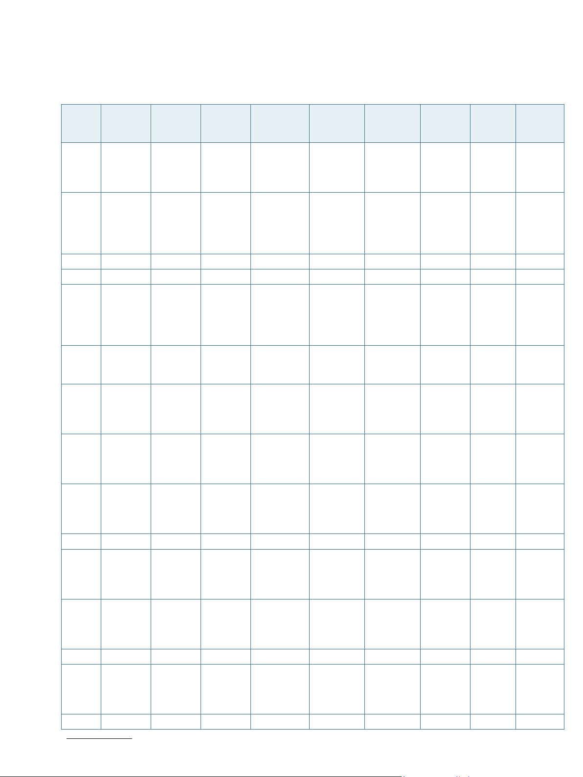
SMARC-sAMX7 User Guide. Rev. 1.5
Pin Signal Module
Directi-
on
CSI0_R
S15
X1-
In -
S16 GND - - - - -
GBE1_
S17
MDI0+
Bi-Dir - GBE MDI
GBE1_
S18
MDI0-
Bi-Dir - GBE MDI
Module
Termination
Type/Tolerance
LVDS DPHY
Controller
iMX7
88E1510
PB2
88E1510
PB2
Controller Pin
Name
MIPI_CSI
_D1_N
Port(i.
MX7
dual)
MIPI_C
SI_D1_
N
Port
(i.MX7
Solo)
MIPI_
CSI_D1
_N
- -
MDI0+ RGMII - -
MDI0- RGMII - -
GBE1_L
S19
S20
S21
INK100
#
Out/OD -
GBE1_
MDI1+ Bi-Dir - GBE MDI
GBE1_
MDI1- Bi-Dir - GBE MDI
CMOS
3.3V
88E1510
PB2
LED_1 RGMII - -
88E1510
PB2 MDI1+ RGMII - -
88E1510
PB2 MDI1- RGMII - -
GBE1_L
S22
S23
S24
INK100
0# Out/OD -
GBE1_
MDI2+
Bi-Dir - GBE MDI
GBE1_
MDI2-
Bi-Dir - GBE MDI
CMOS
3.3V
88E1510
PB2 LED_0 RGMII - -
88E1510
PB2
MDI2+ RGMII - -
88E1510
PB2
MDI1- RGMII - GND
S25 GND Bi-Dir - - - - - - -
S26
S27
GBE1_
MDI3+ Out - GBE MDI
GBE1_
MDI3- Bi-Dir - GBE MDI
88E1510
PB2 MDI3+ RGMII - -
88E1510
PB2 MDI3- RGMII - -
GBE1_C
S28
S29
S30
TREF Bi-Dir - GBE MDI - - - - -
PCIE_D
_TX+
PCIE_D
_TX-
Bi-Dir -
Bi-Dir -
LVDS
PCIe
LVDS
PCIe
- - - - -
- - - - -
GBE1_L
S31
S32
S33
INK_AC
T#
Out/OD -
PCIE_D
_RX+ Bi-Dir -
PCIE_D
_RX- Bi-Dir -
CMOS
3.3V
iMX7
LED_2/I
NT#
RGMII RGMII -
LVDS
PCIe - - - - -
LVDS
PCIe - - - - GND
S34 GND - - - - - - - -
USBDN4
S35 USB4+ Bi-Dir - USB
USB460
4
_DP/PRT
_DIS_P4
HSIC HSIC -
Power
Rail
DDA_1
P8
(1.8V)
GND
www.kontron.com // 34
Page 35
SMARC-sAMX7 User Guide. Rev. 1.5
HDA_S
CMOS
SD2_DA
SAI2_T
SAI2_
NVCC_
Pin Signal Module
Directi-
on
Module
Termination
Type/Tolerance
Controller
Controller Pin
Name
Port(i.
MX7
dual)
Port
(i.MX7
Solo)
Power
Rail
USB_O
TG2_V
DDA
(3.3V)
USBDN4
NVCC_
SAI
(1.8V)
NVCC_
SAI
(1.8V)
S36 USB4- Bi-Dir - USB
USB3_
S37
VBUS_
DET
In -
CMOS
3.3V
USB460
4
iMX7
_DM/PR
T_DIS_M
4 HSIC HSIC
USB_OT
G2_VBU
S
USB_O
TG2_V
BUS
USB_
OTG2_
VBUS
NVCC_
S38
AUDIO_
MCK
Out -
CMOS
1.8V
iMX7
SAI1_MC
LK
SAI1_M
CLK
SAI1_
MCLK
SAI
(1.8V)
NVCC_
S39
I2S0_L
RCK
Bi-Dir -
CMOS
1.8V
iMX7
ENET1_C
RS
SAI1_T
XFS
SAI1_T
XFS
SAI
(1.8V)
NVCC_
S40
I2S0_S
DOUT Out -
CMOS
1.8V iMX7
ENET1_C
OL
SAI1_T
XD
SAI1_T
XD
SAI
(1.8V)
NVCC_
S41
I2S0_S
DIN In -
CMOS
1.8V iMX7
SAI1_RX
D
SAI1_R
XD
SAI1_R
XD
EPDC1
(1.8V)
NVCC_
S42
I2S0_C
K Bi-Dir -
CMOS
1.8V iMX7
SAI1_RX
C
SAI1_R
XC
SAI1_R
XC
EPDC1
(1.8V)
ESPI_A
S43
S44
LERT0
#
ESPI_A
LERT1#
In -
In -
CMOS
1.8V
CMOS
1.8V
iMX7
iMX7
EPDC_D
4
EPDC_D
6
GPIO2_
IO4
GPIO2_
IO7
GPIO2
_IO4
GPIO2
_IO7
-
-
S45 RSVD - - - - - - - GND
NVCC_I
2C
S46 RSVD - - - - - - -
(1.8V)
NVCC_I
2C
S47 GND - - - - - - -
(1.8V)
NVCC_
S48
I2C_GP
_CK Out
PU2k21
CMOS
1.8V iMX7
I2C2_SC
L
I2C2_S
CL
I2C2_
SCL
SD2
(1.8V)
NVCC_
S49
I2C_GP
_DAT
Bi-Dir
PU2k21
CMOS
1.8V
iMX7
I2C2_SD
A
I2C2_S
DA
I2C2_
SDA
SD2
(1.8V)
HDSA_
S50
S51
SYNC/I
2S2_LR
CK
Bi-Dir -
Out -
CMOS
1.5V/1.8V
iMX7
iMX7
SD2_DA
TA2
SAI2_T
XFS
SAI2_
TXFS
NVCC_
SD2
(1.8V)
www.kontron.com // 35
Page 36
SMARC-sAMX7 User Guide. Rev. 1.5
Pin Signal Module
Directi-
on
DO/I2S
Module
Termination
Type/Tolerance
Controller
Controller Pin
Name
Port(i.
MX7
dual)
Port
(i.MX7
Solo)
1.5V/1.8V TA3 XD TXD
2_SDO
UT
HDA_S
S52
DI/I2S2
_SDIN
In -
CMOS
1.5V/1.8V
iMX7
SD2_DA
TA0
SAI2_R
XD
SAI2_
RXD
HDA_C
S53
S54
K/I2S2
_CK Bi-Dir -
SATA_
ACT# - -
CMOS
1.5V/1.8V iMX7
CMOS
3.3V - - - -
SD2_DA
TA1
SAI2_T
XC
SAI2_
TXC -
PRTPWR
S55
S56
S57
S58
USB5_E
N_OC#
ESPI_IO
_2
ESPI_IO
_3
ESPI_R
ESET#
Bi-Dir
OD -
Bi-Dir -
Bi-Dir -
Out -
CMOS
3.3V iMX7
CMOS
1.8V
iMX7
CMOS
1.8V
iMX7
CMOS
1.8V
iMX7
4/PRTCT
L4 HSIC HSIC
EPDC_D1
0
EPDC_D1
1
EPDC_D1
2
QSPIB_
DA2
QSPIB_
DA3
QSPIB_
DQS
QSPIB
_DA2
QSPIB
_DA3
QSPIB
_DQS
USBDN4
S59 USB5+ Bi-Dir - USB
USB460
4
_DP/PRT
_DIS_P4 HSIC HSIC GND
USBDN4
_DM/PR
S60 USB5- Bi-Dir - USB
USB460
4
T_DIS_M
4 HSIC HSIC -
S61 GND - - - - - - - -
S62
S63
USB3_
SSTX+
USB3_
SSTX-
Bi-Dir -
Bi-Dir -
LVDS_AF
B
LVDS_AF
B
- - - - GND
- - - - -
S64 GND - - - - - - - -
S65
S66
USB3_
SSRX+ Bi-Dir -
USB3_
SSRX- Bi-Dir -
LVDS_AF
B - - - - GND
LVDS_AF
B - - - -
S67 GND - - - - - - -
USB_O
S68 USB3+ Bi-Dir -
LVDS_AF
B
iMX7
USB_OT
G2_DP
TG2_D
P
- GND
Power
Rail
SD2
(1.8V)
-
NVCC_
EPDC1
(1.8V)
NVCC_
EPDC1
(1.8V)
NVCC_
EPDC1
(1.8V)
-
-
USB_O
TG2_V
DDA
(3.3V)
USB_O
TG2_V
DDA
(3.3V)
www.kontron.com // 36
Page 37
SMARC-sAMX7 User Guide. Rev. 1.5
Pin Signal Module
Direction
Module
Termination
Type/Tolerance
Controller
Controller Pin
Name
Port(i.
MX7
dual)
Port
(i.MX7
Solo)
USB_O
S69 USB3- Bi-Dir -
LVDS_AF
B iMX7
USB_OT
G2_DN
TG2_D
N - -
S70 GND - - - - - - - -
S71
S72
USB2_
SSTX+
USB2_
SSTX-
Bi-Dir -
Bi-Dir -
LVDS_AF
B
LVDS_AF
B
- - - - GND
- - - - -
S73 GND - - - - - - - -
S74
S75
S76
S77
S78
S79
USB2_
SSRX+ Bi-Dir -
USB2_
SSRX- Bi-Dir -
PCIE_B
_RST# Out -
PCIE_C
_RST#
Out -
PCIE_C
_RX+
In -
PCIE_C
_RX-
In -
LVDS_AF
B - - - - -
LVDS_AF
B - - - - -
CMOS
3.3V
CMOS
3.3V
LVDS
PCIe
LVDS
PCIe
PI7C9X2
G404SL
PI7C9X2
G404SL
PI7C9X2
G404SL
PI7C9X2
G404SL
DWNRST
_2# PCIe - -
DWNRST
_3#
PCIe - -
PER_3+ PCIe - GND
PER_3- PCIe - -
S80 GND - - - - - - - -
S81
S82
PCIE_C
_TX+ Out
PCIE_C
_TX- Out
Seriell100n
Seriell100n
LVDS
PCIe
LVDS
PCIe
PI7C9X2
G404SL PET_3+ PCIe - GND
PI7C9X2
G404SL PET_3- PCIe - -
S83 GND - - - - - - - -
PCIE_B
S84
_REFCK
+
Out -
LVDS
PCIe
PI7C9X2
G404SL
REFCLKO
_2+
PCIe - GND
PCIE_B
S85
_REFCK
-
Out -
LVDS
PCIe
PI7C9X2
G404SL
REFCLKO
_2-
PCIe - -
S86 GND - - - - - - - -
S87
S88
PCIE_B
_RX+ In -
PCIE_B
_RX- In -
LVDS
PCIe
LVDS
PCIe
PI7C9X2
G404SL PER_2+ PCIe - GND
PI7C9X2
G404SL PER_2- PCIe - -
S89 GND - - - - - - - -
S90
S91
PCIE_B
_TX+
PCIE_B
_TX-
Out
Out
Seriell100n
Seriell100n
LVDS
PCIe
LVDS
PCIe
PI7C9X2
G404SL
PI7C9X2
G404SL
PET_2+ PCIe - GND
PET_2- PCIe - -
S92 GND - - - - - - - -
DP0_L
S93
ANE0+ Out - LVDS LCD - - - - -
Power
Rail
www.kontron.com // 37
Page 38
SMARC-sAMX7 User Guide. Rev. 1.5
LVDS1_
SN65DSI
MIPI
MIPI
Pin Signal Module
Direction
Module
Termination
Type/Tolerance
Controller
Controller Pin
Name
Port(i.
MX7
dual)
Port
(i.MX7
Solo)
DP0_L
S94
S95
ANE0- Out - LVDS LCD - - - - -
DP0_A
UX_SEL In -
CMOS
1.8V - - - - -
DP0_L
S96
ANE1+
Out - LVDS LCD - - - - -
DP0_L
S97
S98
ANE1-
DP0_H
PD
Out - LVDS LCD - - - - -
CMOS
In -
1.8V
- - - - -
DP0_L
S99
ANE2+ Out - LVDS LCD - - - - GND
DP0_L
S100
ANE2- Out - LVDS LCD - - - - -
S101 GND - - - - - - - -
DP0_L
S102
ANE3+
Out - LVDS LCD - - - -
DP0_L
S103
S104
ANE3-
USB3_
OTG_ID
Out - LVDS LCD - - - - -
Out -
CMOS
3.3V
iMX7
USB_OT
G2_ID
USB_O
TG2_ID
- -
DP0_A
S105
UX+ Out - LVDS LCD - - - -
DP0_A
S106
S107
UX- Out - LVDS LCD - - - - -
LCD1_B
KLT_EN Out -
CMOS
1.8V iMX7
LCD_DA
TA15
GPIO3_I
O20
GPIO3
_IO20 -
LVDS1_
CK+/eD
P1_AUX
S108
+/DSI1_
CLK+
Out - LVDS LCD
SN65DSI
84
A_CLKP
MIPI
DSI
MIPI
DSI
LVDS1_
CK/eDP1_
AUS-
S109
/DSI1_C
LK-
Out - LVDS LCD
SN65DSI
84
A_CLKN
MIPI
DSI
MIPI
DSI
S110 GND - - - - - - - -
LVDS1_
0+/EDP
1_TX0+
S111
S112
/DSI1_
D0+ Out - LVDS LCD
Out - LVDS LCD
SN65DSI
84 A_Y0P
A_Y0N
MIPI
DSI
MIPI
DSI -
Power
Rail
USB_O
TG2_V
DDA
(3.3V)
NVCC_
LCD
(1.8V)
GND
-
-
www.kontron.com // 38
Page 39
SMARC-sAMX7 User Guide. Rev. 1.5
KLT_P
825R +
Pin Signal Module
Direction
0-
Module
Termination
Type/Tolerance
Controller
Controller Pin
Name
Port(i.
MX7
dual)
84 DSI DSI
/EDP1_
TX0/DSI1_
D0-
S113
eDP1_H
PD
Out -
CMOS
1.8V
- - - - -
LVDS1_
1+/EDP
1_TX1+
S114
/DSI1_
D1+ Out - LVDS LCD
SN65DSI
84 A_Y1P
MIPI
DSI
LVDS1_
1/EDP1_
TX1-
S115
S116
/DSI1_
D1- Out - LVDS LCD
LCD1_V
DD_EN
Out -
CMOS
1.8V
SN65DSI
84 A_Y1N
LCD_DA
iMX7
TA12
MIPI
DSI
GPIO3_I
O17
LVDS1_
2+/eDP
1_TX2+
S117
/DSI1_
D2+
Out - LVDS LCD
SN65DSI
84
A_Y2P
MIPI
DSI
LVDS1_
2/eDP1_
TX2-
S118
/DSI1_
D2-
Out - LVDS LCD
SN65DSI
84
A_Y2N
MIPI
DSI
S119 GND - - - - - - -
LVDS1_
3+/eDP
1_TX3+
S120
/DSI1_
D3+ Out - LVDS LCD
SN65DSI
84 A_Y2P
MIPI
DSI
LVDS1_
3/eDP1_
TX3-
S121
S122
/DSI1_
D3- Out - LVDS LCD
LCD1_B
Ser-
Out
CMOS
1.8V
SN65DSI
84 A_Y2N
GPIO1_IO
iMX7
03
MIPI
DSI
GPIO1_I
O03
Port
(i.MX7
Power
Rail
Solo)
NVCC_
LCD
(1.8V)
MIPI
DSI -
MIPI
DSI -
GPIO3
_IO17
GND
MIPI
DSI
-
MIPI
DSI
-
NVCC_
GPIO1
(3.3V)
MIPI
DSI -
MIPI
DSI GND
GPIO1
_IO03
-
www.kontron.com // 39
Page 40
SMARC-sAMX7 User Guide. Rev. 1.5
X+/DSI
Pin Signal Module
Direction
Module
Termination
Type/Tolerance
Control-
ler
Controller Pin
Name
Port(i.
MX7
dual)
Port
(i.MX7
Solo)
Power
Rail
WM PD-1k
S123 RSVD Out - - - - - - -
NVCC_
LCD
S124 GND - - - - - - -
(1.8V)
LVDS0_
0+/eDP
0_TX0+
S125
/DSI0_
D0+ Out - LVDS LCD
SN65DSI
84 B_Y0P
MIPI
DSI
MIPI
DSI -
-
GND
LVDS0_
0/eDP0_
TX0-
S126
/DSI0_
D0-
Out - LVDS LCD
SN65DSI
84
B_Y0N
MIPI
DSI
MIPI
DSI
-
LCD0_
S127
BKLT_E
N
Out -
CMOS
1.8V
iMX7
LCD_DA
TA13
GPIO3_I
O18
GPIO3
_IO18
-
LVDS0_
1+/eDP
NVCC_
LCD
(1.8V)
S128
0_TX1+
/DSI0_
D1+ Out - LVDS LCD
SN65DSI
84 B_Y1P
MIPI
DSI
MIPI
DSI
LVDS0_
1/eDP0_
TX1-
S129
/DSI0_
D1- Out - LVDS LCD
SN65DSI
84 B_Y1N
MIPI
DSI
MIPI
DSI -
S130 GND - - - - - - - -
LVDS0_
2+/eDP
0_TX2+
S131
/DSI0_
D2+
Out - LVDS LCD
SN65DSI
84
B_Y2P
MIPI
DSI
MIPI
DSI
GND
LVDS0_
2/eDP0_
TX2-
S132
S133
/DSI0_
D2-
LCD0_V
DD_EN
Out - LVDS LCD
CMOS
Out -
1.8V
SN65DSI
84
iMX7
B_Y2N
LCD_DA
TA14
MIPI
DSI
GPIO3_I
O20
MIPI
DSI
GPIO3
_IO20
-
-
LVDS0_
CK+/eD
P0_AU
S134
www.kontron.com // 40
Out - LVDS LCD
SN65DSI
84
B_CLKP
MIPI
DSI
MIPI
DSI
NVCC_I
2C
(1.8V)
Page 41
SMARC-sAMX7 User Guide. Rev. 1.5
Pin Signal Module
Direction
Module
Termination
Type/Tolerance
Control-
ler
Controller Pin
Name
Port(i.
MX7
dual)
Port
(i.MX7
Solo)
0_CLK+
LVDS0_
CK/eDP0_
AUX-
S135
/DSI0_
CLK-
Out - LVDS LCD
SN65DSI
84
B_CLKN
MIPI
DSI
MIPI
DSI
S136 GND - - - - - - -
-
LVDS0_
3+/eDP
0_TX3+
S137
/DSI0_
D3+ Out - LVDS LCD
SN65DSI
84 B_Y3P
MIPI
DSI
MIPI
DSI GND
LVDS0_
3/eDP0_
TX3-
S138
S139
S140
/DSI0_
D3-
I2C_LC
D_CK
I2C_LC
D_DAT
Out - LVDS LCD
Out
Bi-Dir
PU2k21
PU2k21
CMOS
1.8V
CMOS
1.8V
SN65DSI
84
iMX7
iMX7
B_Y3N
UART1_R
XD
UART1_T
XD
MIPI
DSI
MIPI
DSI
I2C1_SCL I2C1_S
CL
I2C1_S
DA
I2C1_S
DA
LCD0_
S141
BKLT_P
WM Out -
CMOS
1.8V iMX7
GPIO1_IO
09
PWM2
_OUT
PWM2
_OUT
S142 RSVD - - - - - - -
S143 GND - - - - - - -
S144
EDP0_
HPD
- -
CMOS
1.8V
- - - - -
WDOG
S145
S146
S147
WDT_T
IME_O
UT#
PCIE_W
AKE #
VDD_R
Out -
In
-
PU4k75
Ser-1k
CMOS
1.8V
iMX7
CMOS
3.3V
iMX7
PWR iMX7
ENET1_R
X_CLK
SAI1_TXFS GPIO6_
VDD_SN VDD_S VDD_ NVCC_
WDOG2
#/GPIO
7_IO13
IO14
2#/GP
IO7_IO
13
GPIO6
_IO14
Power
Rail
NVCC_I
2C
(1.8V)
NVCC_
GPIO2
(1.8V)
-
NVCC_
ENET1
(1.8V)
NVCC_
SAI
(1.8V)
VDD_S
NVS_I
N (3V)
NVCC_
LCD
(1.8V)
NVCC_
LCD
(1.8V)
NVCC_
SD2
(1.8V)
NVCC_
SD2
(1.8V)
www.kontron.com // 41
Page 42

SMARC-sAMX7 User Guide. Rev. 1.5
Pin Signal Module
Direction
TC + Diode VS_IN NVS_IN
S148 LID# In
Module
Termination
PU4k75
Type/Tolerance
CMOS
1.8V
Control-
ler
iMX7
Controller Pin
Name
LCD_DA
TA8
Port(i.
MX7
dual)
GPIO3_I
O13
Port
(i.MX7
Solo)
SNVS_
IN
GPIO3
_IO13
Power
Rail
SNVS_I
N (3V)
-
NVCC_
S149 SLEEP# In
VIN_P
WR_BA
S150
D# In W-PU
CHARGI
S151
NG# In
PU4k75
PU4k75
CMOS
VDDIN iMX7
LCD_DA
TA9
GPIO3_I
O14
CMOS
1.8V POWER - - -
CMOS
1.8V iMX7 SD2_CLK
GPIO5_I
O12
GPIO3
_IO14
GPIO5
_IO12 -
GPIO1
(3.3V)
NVCC_
LCD
(1.8V)
GND
CHARG
S152
S153
ER_PRS
NT#
CARRIE
R_STBY
#
In
Out -
PU4k75
CMOS
1.8V
CMOS
1.8V
iMX7 SD2_WP
PMIC_ST
iMX7
BY_REQ
GPIO5_I
O10
PMIC_S
TBY_RE
Q
GPIO5
_IO10
PMIC_
STBY_
REQ
-
-
CARRIE
S154
S155
R_PWR
_ON Out
FORCE_
RECOV
# In
PD2k21
PU4k75
CMOS
1.8V POWER - - - GND
BOOT
CMOS
1.8V iMX7
BOOT_M
ODE0
BOOT_
MODE0
_MOD
E0 -
NVCC_
BATLO
S156
W# In
S157 TEST# In
PU_2k21 CMOS
1.8V iMX7
PU-10k
+ FET
CMOS
1.8V
PI7C9X2
G404SL
LCD_RES
ET
JTAG_M
OD
GPIO3_I
O04
GPIO3
_IO04
- - -
EPDC1
(1.8V)
S158 GND - - - - - - - GND
www.kontron.com // 42
Page 43
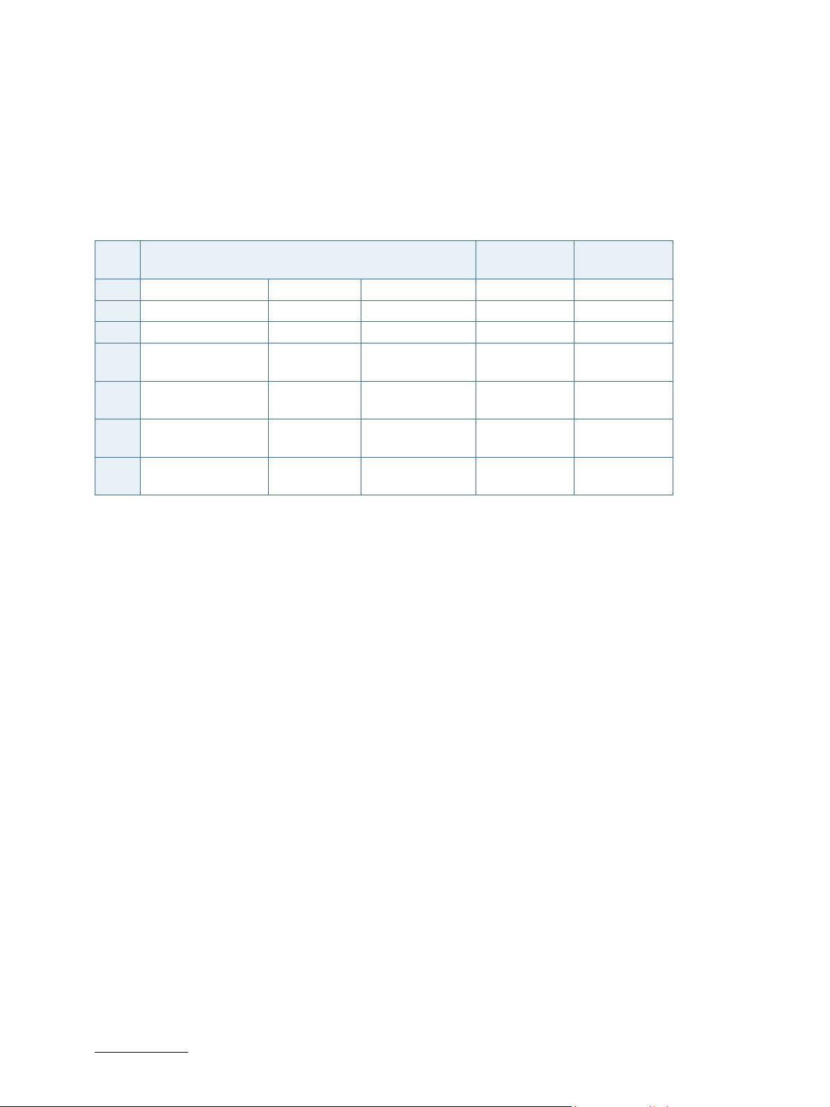
SMARC-sAMX7 User Guide. Rev. 1.5
BOOT_SEL2#
BOOT_SEL1#
BOOT_SEL0#
6/ Installation
6.1. Boot Mode
The following table shows the possible boot sources on the carrier board defined in SMARC 2.0 spec:
Table 10: Boot Options on the carrier board
Carrier Connection Boot Source Supported on
sAMX7
0 GND GND GND Carrier SATA No
1 GND GND Float Carrier SD Card From U-Boot
2 GND Float GND Carrier eSPI
(CS0#)
3 GND Float Float Carrier SPI
(CS0#)
4 Float GND GND Module device
(NAND, NOR)
5 Float GND Float Remote boot
(GBE, serial)
From U-Boot
From U-Boot
No
From U-Boot
U-Boot only supports booting from QSPI NOR flash because "boot from fuses" is defined per default.
6.2. Configurable Watchdog
As no CPLD is available, the Watchdog must be used from the SoC. The WDOG features are listed below:
Configurable timeout counter with timeout periods from 0.5 to 128 seconds which, after timeout expiration,
result in the assertion of WDOG_RESET_B_DEB reset signal .
Time resolution of 0.5 seconds
Configurable timeout counter that can be programmed to run or stop during low-power modes
Programmable interrupt generation prior to timeout
The duration between interrupt and timeout events can be programmed from 0 to 127.5 seconds in steps of
0.5 seconds.
www.kontron.com // 43
Page 44

SMARC-sAMX7 User Guide. Rev. 1.5
V_BAT
GND
GND
NC
NC
GND
GND
GND
NC
J37
2
1
V_RTC
BT1
3V
CR2032
V_BAT_R
D32
BAV99
SOT23
3
2
1
V_BAT_D
V_5V0_S5
1
2
3
D54
BAV99
SOT23
V_SCAP
1
2
3
D55
BAV99
SOT23
RTC
V_SCAP_RTC
P1
P2
P3
1
2
3
J58
JUMPER
H10
V_BAT_JP
V_SCAP_JP
U7
2
5
1
3
4
VOUT
GND
CE
V_VIN
NC
NCP4681
GND
NC
R1151k
1% 0402
R85221R
1% 0402
21.5x85.5V
1 5 C364
C208100n
50V 0402
040250V
100n C2
09
R1531k
1% 0402
04021%
0R R442
DNI
DNI
R4430R
1% 0402
D37
BAV99
SOT23
3
2
1
NC
V_3V3_S5
6.3. RTC current consumption
The current consumption of the sAMX7 was tested with following circuit. Jumper was populated to J58 position 1-2.
With an external power supply J37 was feed with voltages from 2.0 V to 3.4 V.
Figure 8: RTC current consumption with an external power supply and voltages from 2.0 V to 3.4 V
The module RTC (RV-8803) can operate down to 1.5V, the i.MX7 RTC minimum supply voltage is 2.4V.
Table 11: Minimum Supply Voltage of the RTC Module
Ambient
temperature
-20°C
25°C
85°C
Because of the high voltage drop of the BAV99 diode on the SMARC Eval-Carrier 2.0, only the module RTC (RV-8803)
will keep the time on cold ambient temperatures.
Therefore for using i.MX7 RTC also – this is not recommended, because the accuracy is worse than RV8803 – BAV99
should be replaced with a suitable Schottky diode which has lower voltage drop.
Because the sAMX7 module has a reverse serial protection in the VDD_RTC signal with a diode, no super cap
charging from module side is possible without shorting the diode on the module.
www.kontron.com // 44
Maximum
Current in V_BAT
3.6 µA
5 µA
5.2 µA
Minimum voltage
for i.MX7 RTC
3.11 V 2.21 V
Minimum voltage for
module RTC (RV-8803)
2.93 V 2.10 V
2.99 V 2.10 V
Page 45

6.4. UART Interfaces
Use following UART interfaces with control signals of i.MX7.
Table 12: Mapping of SMARC SER interfaces to i.MX7 UARTs
SER UART
SER0 UART6
SER1 UART4
SER2 UART7
SER3 UART5
Table 13: UART interfaces for SER0 and SER2 (RX, TX, CTS#, RTS#)
UART6 UART7
UART6_CTS#//ECSPI1_SS0/H5
UART6_RTS#/ECSPI1_MISO/H4
UART6_RXD/ECSPI1_SCLK/H3
UART6_TXD/ECSPI1_MOSI/G5
depends on IO Pin muxing, table corresponds to Kontron default settings
UART7_CTS#/J6
UART7_RTS#/H6
UART7_RXD/J5
UART7_TXD/G6
SMARC-sAMX7 User Guide. Rev. 1.5
NXP has defined the UART handshake lines in the opposite way from many other vendors. In the SMARC 2.0
specification RTS is defined as an output and CTS as an input. This is the same definition used by the standard PC
serial port.
However, in the iMX7 implementation RTS is an input and CTS is an output – i.e. the pin functions corresponding to
these names are swapped.
Per table 17 below, configuring the UART for DTE mode will result in the signals being routed to the SMARC pins in
conformance with the SMARC definition of the pin functions.
Table 14: UART interfaces for SER1 and SER3 (RX, TX)
UART4 UART5
UART4_RXD/SAI2_TXFS/D9
UART4_TXD/SAI2_TXC/D8
depends on IO Pin muxing, table corresponds to Kontron default settings
The DTE mode is designated for the SMARC-sAMX7 module. Following additional UART interfaces can be optionally
used:
UART1 shares I2C1 at i.MX7 and I2C_LCD pins at SMARC 2.0 connector. They are only useable if display
converter (SN65DSI84ZQER) is not placed.
UART2 shares SPI[4]_Master Input, Slave Output/Master Output, Slave Input (MISO/MOSI) at i.MX7 and
GPIO7/GPIO8 pins at SMARC 2.0 connector. They are only useable if APPROTECT key does not use SPI option
with additional resistors and omit SPI level shifter TXB0104RUT.
UART3 shares 2x GPIOs at i.MX7 and GPIO9/GPIO10 pins at SMARC 2.0 connector.
UART5_RXD/I2C4_SCL/L1
UART5_TXD/I2C4_SDA/L2
www.kontron.com // 45
Page 46

SMARC-sAMX7 User Guide. Rev. 1.5
UART port mapping in DCE/DTE mode defines RTS_B and CTS_B in different manner as used in SMARC 2.0 spec. In
the following table the pin and signal direction are like in SMARC 2.0 spec.
Table 15: UART port mapping in DCE/DTE mode
IO Pads Name DCE mode DTE mode
UART function IO direction UART function IO direction
UARTx_CTS# RTS# Output SERx_CTS# Input
UARTx_RTX# CTS# Input SERx_RTS# Output
UARTx_TXD TX Output SERx_RX Input
UARTx_RXD RX Input SERx_TX Output
Table 16: UART connections between CPU and SMARC 2.0 connector
CPU
Interface
CPU pins Function SMARC 2.0
connector
UART11 UART1_RXD/I2C1_SCL/L3 DTE_TX I2C_LCD_SCL/S139
UART1_TXD/I2C1_SDA/L4 DTE_RX I2C_LCD_SDA/S140
UART22 LCD_CLK/ECSPI4_MISO/UART2_R
DTE_TX GPIO[7]/P115
XD/E20
LCD_ENABLE/ECSPI4_MOSI/UART
DTE_RX GPIO[8]/P116
2_TXD/F25
UART3 UART3_RXD/GPIO4_IO04/M1 DTE_TX GPIO[9]/P117
UART3_TXD/GPIO4_IO05/M2 DTE_RX GPIO[10]/P118
UART4 SAI2_TXFS/UART4_RXD/D9 DTE_TX SER[1]_TX/P134
SAI2_TXC/UART4_TXD/D8 DTE_RX SER[1]_RX/P135
UART5 I2C4_SCL/UART5_RXD/L1 DTE_TX SER[3]_TX/P140
I2C4_SDA/UART5_TXD/L2 DTE_RX SER[3]_RX/P141
UART6 ECSPI1_SCLK/UART6_RXD/H3 DTE_TX SER[0]_TX/P129
ECSPI1_MOSI/UART6_TXD/G5 DTE_RX SER[0]_RX/P130
ECSPI1_MISO/UART6_RTS#/H4 DTE_RTS# SER[0]_RTS#/P131
ECSPI_SS0/UART6_CTS#/H5 DTE_CTS# SER[0]_CTS#/P132
UART7 ECSPI2_SCLK/UART7_RXD/J5 DTE_TX SER[2]_TX/P136
ECSPI2_MOSI/UART7_TXD/G6 DTE_RX SER[2]_RX/P137
ECSPI2_SS0/UART7_CTS#/J6 DTE_CTS# SER[2]_CTS#/P139
ECSPI2_MISO/UART7_RTS#/H6 DTE_RTS# SER[2]_RTS#/P138
1
Only usable if no I2C device is connected at I2C_LCD bus, therefore display converter has to be omit
2
Only usable if APPROTECT key does not use SPI (omit SPI level shifter TXB0104RUT) and stuffed additional
resistors
www.kontron.com // 46
Page 47

SMARC-sAMX7 User Guide. Rev. 1.5
Pressing the power button for at least 4 seconds will turn off power to the module
(Power Button Override).
6.5. Power Control
6.5.1. Power Supply
The SMARC-sAMX7 supports a power input from 3.0 to 5.25V. The supply voltage is applied through the VCC pins
(VCC) of the module connector. Considered current rating of protective device is part of End-Equipment.
The following parameters should be delivered from the carrier board:
Voltage Ripple maximum 100 mV peak to peak 0-20 MHz to 20 ms rise time from
input voltage <10% to nominal VCC
Max allowed inrush current: connector limit (15 W @ 3,0 V)
6.5.2. Power Button (POWER_BTN#)
The power button (Pin P128) is available through the module connector described in the pinout list. To start the
module via Power Button the PWRBTN# signal must be at least 50 ms (50 ms ≤ t < 4 s, typical 400 ms) at low level
(Power Button Event).
6.5.3. Power Bad Signal (VIN_POWER_BAD#)
The SMARC-sAMX7 provides an external input for a Carrier Board Power Bad signal (Pin S150). The implementation
of this subsystem complies with the SMARC Specification. VIN_POWER_BAD# is internally pulled up to 3.3V and
must be high level to power on the module.
6.5.4. Reset Button (RESET_IN#)
The reset button (Pin P127) is available through the module connector described in the pinout list. The module will
stay in reset as long as RESET_IN# is grounded.
www.kontron.com // 47
Page 48
SMARC-sAMX7 User Guide. Rev. 1.5
115200 baud, 8 data bits, 1 stop bit, no parity
7/ Bootloader Operation
7.1. Copyrights and Licensing of U-Boot
U-Boot is free Software. It is copyrighted by Wolfgang Denk and many others who contributed code. U-Boot can be
redistributed and modified under the terms of version 2 of the GNU General Public (GPL V2) License as published by
the Free Software Foundation.
Actual source code of mainline U-Boot and authors of the source can be obtained from the git repository at
git://git.denx.de/u-boot.git
SMARC-sAMX7 bootloader sources are derived work from a dedicated version of mainline U-Boot, e.g v2017.03. As
bootloader evolves, the root of the derived work might change to a later version.
The source code of U-Boot will be delivered with the standard software package.
Additionally the software can be downloaded from Kontron GitHub repository for SMARCsAMX7: https://github.com/kontron/u-boot-smarc-samx7
7.2. Bootloader Quickstart
The SMARC-sAMX7 board comes with U-Boot preinstalled on the QSPI flash device. Follow the steps below to gain
access to the bootloader command line (CLI) on your host PC.
Connect your host machine to the carrier port connected with the edge connector SER0 port of the module.
On Kontron SMARC 2.0 carrier this port is named SER_0.
Start a suitable terminal program on your host and attach it to the port connected with the board’s serial
interface. Configure the serial line using
Connect power supply to the carrier and power up.
When boot messages appear, press any key to stop automatic boot sequence.
After power on, bootloader boot messages will appear as shown below. There is a 3 second boot delay counter that
will try to boot linux OS automatically after expiration. Pressing any key will stop the boot delay counter and enter
the bootloader CLI
.
U-Boot <Version> (<Date-code>)
CPU: Freescale i.MX7D rev1.2 at 996MHz
CPU: Extended Commercial temperature grade (-20C to 105C) at 54C
Reset cause: POR
Board: Kontron SMX7 SMARC 2.0 Module
I2C: ready
DRAM: 2 GiB
MMC: FSL_SDHC: 0, FSL_SDHC: 1
SF: Detected w25q16dw with page size 256 Bytes, erase size 4 KiB, total 2 MiB
In: serial
Out: serial
Err: serial
Net: FEC0, FEC1
Hit any key to stop autoboot: 0
=>
.
www.kontron.com // 48
Page 49
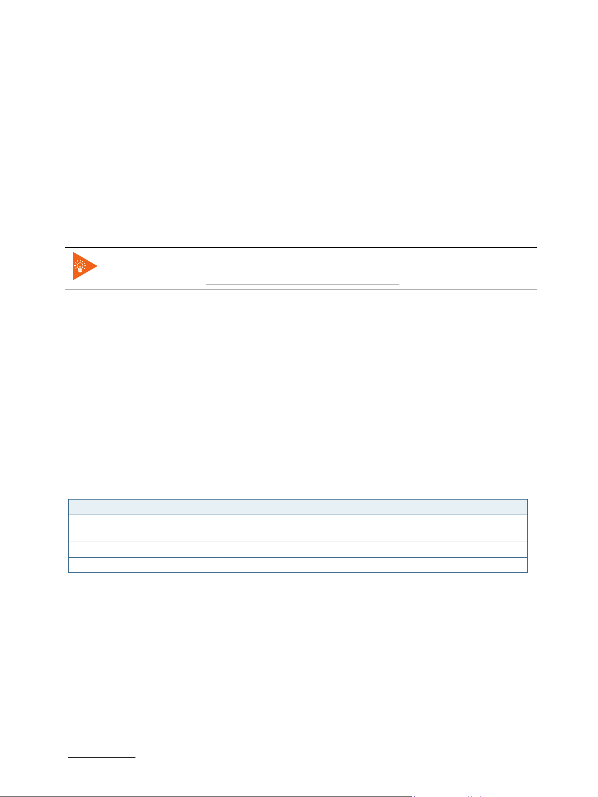
SMARC-sAMX7 User Guide. Rev. 1.5
7.3. Bootloader Commands
The bootloader CLI provides a bunch of powerful commands to control the board, which basically can be grouped
into
Information Commands
Memory Commands
Flash Memory Commands
Execution Control Commands
Download Commands
Environment Control Commands
Flattened Device Tree Support Commands
Storage Device Control Commands
File System Support Commands
Kontron Command Extensions
Typing “help” at the bootloader command line prompt will show up a list of the commands
available. Typing “help <command>” will show specific command help. Further help can be
On the SMARC_sAMX7 bootloader, the powerful hush shell is enabled, which is similar to Bourne shell and provides
features similar to a linux shell:
found under https://www.denx.de/wiki/view/DULG/UBoot
Control structures (if … then … else … fi etc.)
Command line completion
Command line editing
Command line history up to 20 entries
Local environment variables
7.4. Kontron Bootloader Command Extensions
Kontron’s implementation of U-Boot includes certain enhancements to provide board specific functions. They are
not part of standard U-Boot as maintained by DENX. The following table provides a complete listing of all Kontron
command extensions on the SMARC-sAMX7.
Table 17: Bootloader Command Extensions
Command Description
kboardinfo Kontron Board Information - Displays a summary of board and
configuration information
md5sum Creates or checks the md5 message digest over a memory area
watchdog Start and control i.MX7 CPU watchdog
7.4.1. kboardinfo - Kontron Board Information
The "kboardinfo" command shows a summary of board serialization data gathered from the system EEPROM.
=> kboardinfo
Manufacturer: Kontron Europe GmbH
Product name: SMARC-sAMX7
Material number: 51009-0208-10-2
Serial number: NZD070001
MAC0 (ethaddr): 00:a0:a5:79:25:30
MAC1 (eth1addr): 00:a0:a5:79:25:31
Manufacturer Date: 11/15/2017
Revision: B00
Boot Counter: 10
www.kontron.com // 49
Page 50

SMARC-sAMX7 User Guide. Rev. 1.5
Syntax:
Example:
Syntax:
CPU: Freescale i.MX7D rev1.2 at 996 MHz
==>
7.4.2. md5sum – MD5 Message Digest
The "md5sum" command is already part of standard U-Boot implementation. However Kontron provides the "-a"
extension (ASCII) that allows to check MD5 checksum of a given memory area (e.g. a binary image copied into
memory) against the checksum that has been copied into an ASCII file on an external linux host. To achieve this, the
ASCII string in the file representing the checksum is converted into hexadecimal values and compared against the
calculated one.
=> help md5sum
md5sum - compute MD5 message digest
Usage:
md5sum address count [[*]sum]
- compute MD5 message digest [save to sum]
md5sum -v address count [*]sum
- verify md5sum of memory area
md5sum -a address count [*]sum
- verify md5sum given in ASCII format
Calculate MD5 checksum of a given binary using the md5sum command on linux host and redirect output messages
into a file:
# md5sum image.bin >image.md5
Copy both image file and checksum file to USB thumb device with EXT2/3/4 or FAT partition. Connect the USB device
to the module carrier.
The following sequence shows how to load both image file and image checksum file into SMARC_sAMX7 memory
and compare them. In case of success, the "md5sum -a" command will have no output messages as this extensions
is meant to be used in automatic update scripts to check the binary images against their MD5 checksum.
usb start
load usb 0:1 88000000 <image.bin>
load usb 0:1 8a000000 <image.md5>
if md5sum -a 88000000 $ubootsz *88a00000; then
echo ‘CRC check passed’
else
echo ‘CRC check failed’
fi
7.4.3. Watchdog – CPU Watchdog Control
The "watchdog" command is used to control the i.MX7 CPU internal watchdog. After watchdog has been started
using "watchdog start", the watchdog is kicked periodically by U-Boot to prevent expiration.
Watchdog timeout can be changed at any time. However, it is not possible to stop watchdog
once it has been started.
www.kontron.com // 50
=> help watchdog
watchdog - start/stop/kick IMX watchdog
Usage:
watchdog <timeout> - kick watchdog and set timeout (0 = disable kicking)
Page 51
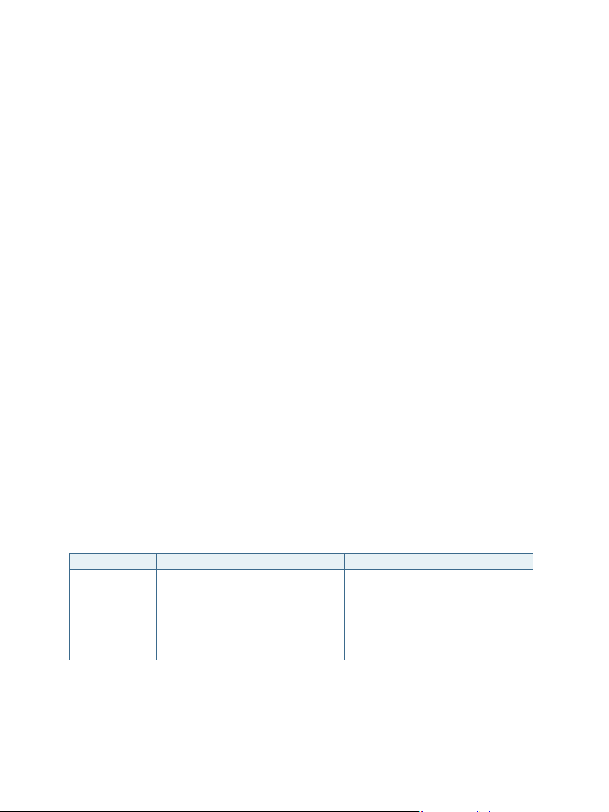
SMARC-sAMX7 User Guide. Rev. 1.5
Example
watchdog start <timeout> - start watchdog and set timeout
Start watchdog with 5 seconds timeout and stop kicking watchdog some time later. Board will reset after watchdog
has been expired.
:
=> watchdog 5
=> watchdog 0
7.5. Bootloader Environment
The bootloader environment is used to control bootloader and OS startup behavior. Environment variables can be
used to control boot timing (e.g. bootdelay), interface properties (e.g. baudrate, ethact) or they define memory
locations where OS images are stored before boot (e.g. loadaddr, fdt_addr). In addition, bootloader shell commands
can be combined to environment scripts.
The redundant bootloader environment is permanently stored in the QSPI flash device at offset 0x1C0000 and
0x1C8000. During bootloader operation, the environment is held in RAM memory and can be modified and written
back to persistent storage.
Bootloader commands to modify the environment are summed up under the "env" command group:
env default [-f] –a [forcibly] reset default environment
env default [-f] var [...] [forcibly] reset variable(s) to their default values
env delete [-f] var [...] [forcibly] delete variable(s)
env edit name edit environment variable
env exists name tests for existence of variable
env print [-a | name ...] print environment
env run var [...] run commands in an environment variable
env save save environment
env set [-f] name [arg ...]
However, the legacy commands for environment handling are still available:
"setenv",
"editenv",
"printenv"
"saveenv".
U-Boot standard environment variables are set up for the SMARC_sAMX7 module as shown below
Table 18: Standard Environment Variables
Variable Value Description
baudrate 115200 Serial line baudrate
bootcmd Run mmcboot || run sdboot || run usbboot ||
run netboot || run bootfailed
bootdelay 3 Wait 3 seconds before executing bootcmd
ethprime FEC0 Use Ethernet port FEC0 as default
loadaddr 0x80800000 Default memory location for OS boot
A typical user modification would be to set the variable "bootcmd" to change OS boot commands.
Try booting (in this order) from eMMC, SD
card, USB, network
www.kontron.com // 51
Page 52
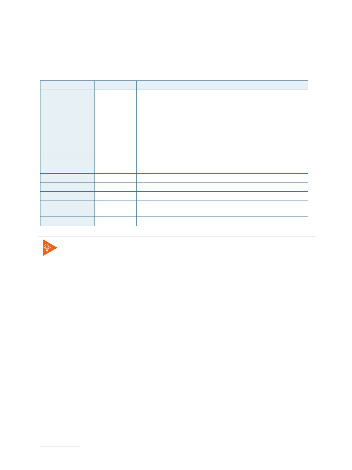
SMARC-sAMX7 User Guide. Rev. 1.5
Example:
Example:
7.6. Kontron Bootloader Environment Extensions
To support SMARC_sAMX7 board properly, Kontron adds some environment variables to the standard set of
variables provided by mainline U-Boot. These variables are shown below.
Table 19: Bootloader Environment Extensions
Variable Value Description
boot_sel Depends on
BOOT_SEL
lines
core_variant d
s
eth1addr From EEPROM Ethernet port FEC1 MAC address
ethaddr From EEPROM Ethernet port FEC0 MAC address
fdt_addr 0x83000000 Memory location for device tree blob
panel Default: ld101 Describes the panel type attached to the module. It is used to select
pcie_a_prsnt yes Enable/disable PCIE_A PRSNT line to reduce power consumption
pcie_b_prsnt yes Enable/disable PCIE_B PRSNT line to reduce power consumption
pcie_c_prsnt yes Enable/disable PCIE_C PRSNT line to reduce power consumption
pwm_out_disable yes Enable/disable PWM_OUT signal. When disabled, GPIO5 pin on
serial# From EEPROM Module serial number
BOOT_SEL lines from carrier are evaluated during startup and
boot_sel is set appropriately. See chapter 7.10 Bootloader Boot
Source for more detail
Set to "s" for i.MX7S module, "d" for i.MX7D module.
the appropriate device tree file
SMARC edge connector is used as GPIO.
Variables from the table above marked in bold are set automatically each time U-Boot
starts. They will override different settings possibly stored in persistent environment.
7.7. Bootloader Mass Storage Support
U-Boot provides support to read and write from mass storage devices like
QSPI flash
eMMC device
SD card
USB thumb device
7.7.1. QSPI flash
QSPI flash is accessed using the "sf" command
Load one sector (64K) from SPI flash
=> sf probe 0
=> sf read ${loadaddr} 0 10000
7.7.2. SD Card and eMMC Devices
eMMC and SD card are accessed using the "mmc" command
www.kontron.com // 52
Load 256 blocks from eMMC
=> mmc dev 1
=> mmc read ${loadaddr} 0 100
Page 53

Example:
Example:
Example:
7.7.3. USB Storage Device
USB storage devices are accessed using "usb" command
SMARC-sAMX7 User Guide. Rev. 1.5
Load bootloader update file from USB thumb device
=> usb start
=> usb dev 0
=> fatload usb 0:1 update_smx7_spl/u-boot-smx7_spl.bin
7.8. Bootloader File System Support
U-Boot for the SMARC_sAMX7 provides support for FAT and EXT4 file systems. EXT4 support also includes EXT2
and EXT3 formatted file systems. There are file system specific commands available to list file system contents
(ext2ls, fatls) and load a given file into board memory (ext2load, fatload). However, U-Boot also provides generic
commands ("ls" and "load"), that will detect the file system on the device and use appropriate file system functions
automatically.
Show /boot folder contents from SD card file system
=> ls mmc 0:1 /boot
<DIR> 4096 .
<DIR> 4096 ..
<SYM> 48 imx7d-samx7-ld101-m4.dtb
44034 devicetree-zImage-imx7d-samx7-ld101-m4.dtb
43986 devicetree-zImage-imx7d-samx7-ld101.dtb
<SYM> 33 zImage
<SYM> 45 imx7d-samx7-ld101.dtb
<SYM> 45 imx7s-samx7-ld101.dtb
6376512 zImage-4.1.29-fslc+g59b38c3
43998 devicetree-zImage-imx7s-samx7-ld101.dtb
=> load mmc 0:1 ${loadaddr} /boot/zImage
6376512 bytes read in 536 ms (11.3 MiB/s)
7.8.1. EXT4 File System Write Support
There is even support available to write a given memory area into ext4 formatted file systems. However, the
implementation is not bullet proof und should be used with care, as this could lead to file system corruption.
Writing to symbolic links in an ext4 filesystem does not work from u-boot!
Do not create new files in ext4 filesystem as this could cause problems.
7.9. Bootloader Network Support
U-Boot provides support for both onboard Ethernet interfaces. The current interface can be selected by setting
"ethact" environment variable to either “FEC0” or “FEC1”.
Board specific MAC addresses are read from EEPROM during startup and environment variables are set
automatically. In case EEPROM contents is missing or corrupted, a "random" MAC address will be set to "ethaddr"
In case that the current network interface is attached to a network providing a DHCP server, an IP address can be
gathered using "bootp" ord "dhcp" commands.
After that, a file from a tftp server can be copied to memory using the "tftpboot" command.
=> bootp
=> tftpboot ${loadaddr} <filename>
www.kontron.com // 53
Page 54
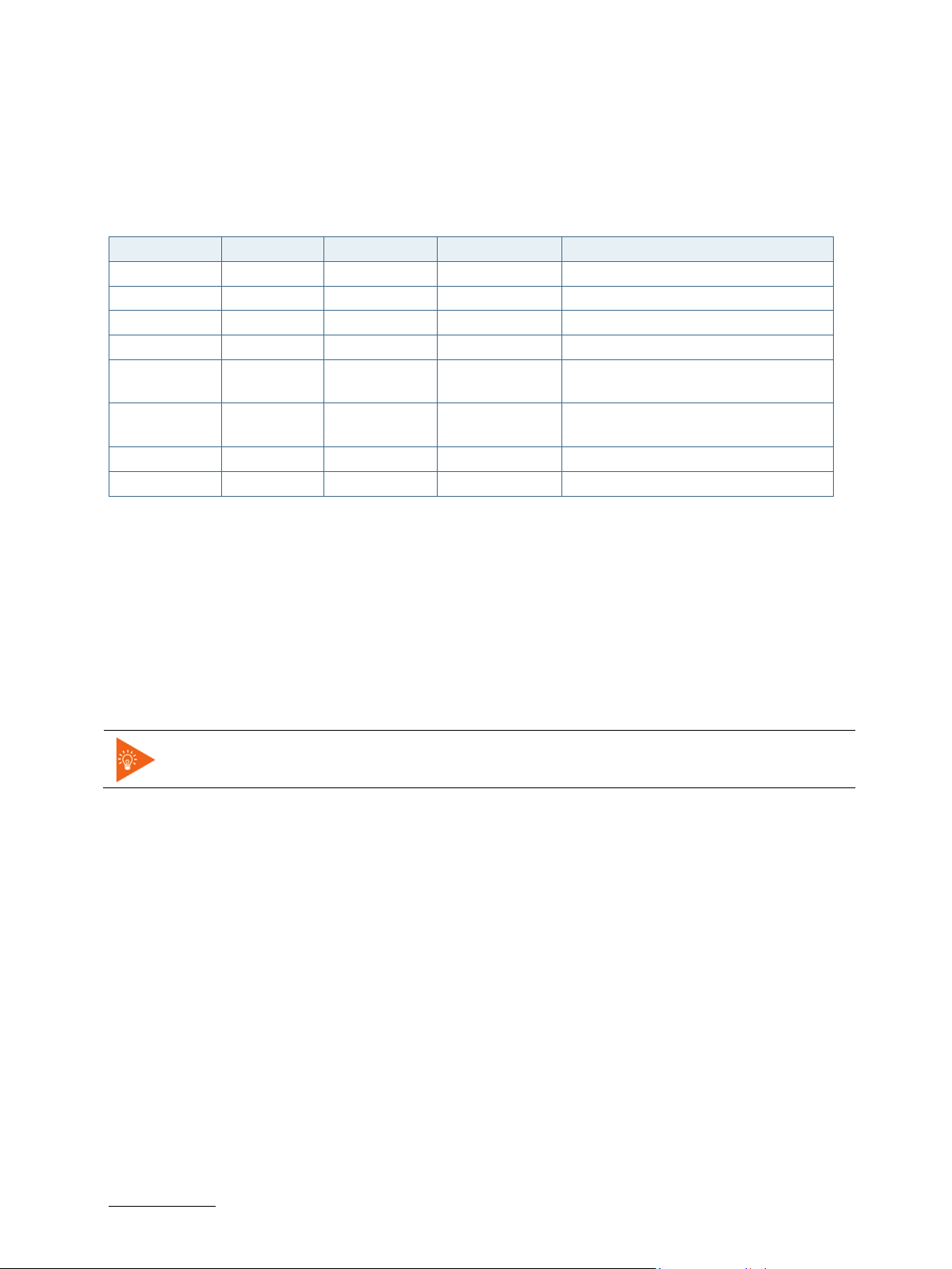
SMARC-sAMX7 User Guide. Rev. 1.5
7.10. Bootloader Boot Source Support
The SMARC v2.0 Specification defines three boot select signals BOOT_SEL[0:2]# that allows the user to select from
eight possible boot devices. On the SMARC_sAMX7, U-Boot detects the BOOT_SEL signals from the carrier and sets
the environment variable "boot_sel" as shown below.
Table 20: Environment Variables for "boot_sel"
BOOT_SEL2# BOOT_SEL1# BOOT_SEL0# boot_sel Boot Source
GND GND GND carrier_sata Carrier SATA
GND GND Float carrier_sd Carrier SD Card
GND Float GND carrier_mmc Carrier eSPI (CS0#)
GND Float Float carrier_spi Carrier SPI (CS0#)
Float GND GND module_device Module Device (NAND, NOR) – vendor
specific
Float GND Float remote Remote boot (GBE, serial) – vendor
specific
Float Float GND module_mmc Module eMMC Flash
Float Float Float module_spi Module SPI
Bootloader environment scripts can use the boot_sel environment variable to select the source where the dedicated
OS image can be loaded. As an example, the bootloader environment of the SMARC_sAMX7 implements some small
scripts that will load a linux system from the boot source as defined by the BOOT_SEL pins.
bootsel_boot=echo BOOT_SEL ${boot_sel} selected && run ${boot_sel}_boot
module_mmc_boot=run mmcboot
module_spi_boot=run mmcboot
Running the "run bootsel_boot" script will load a linux system from MMC if BOOT_SEL pins define the module MMC
Flash or the Module SPI as boot source. Depending on application, the script variables in environment can be
adapted.
The bootloader is always booted from the boot source defined by fuse settings, which is
normally the QSPI flash device. The BOOT_SEL pins only define boot source for the OS.
7.11. Bootloader Boot Counter
The module EEPROM device contents implements a SMBIOS Running-time data block (type 161) as defined in the
KEU EEPROM Specification Rev. 1.4. The running-time data block structure implements a 64bit boot counter. U-Boot
on the SMARC_sAMX7 module will read the current boot counter value and increment it on every boot cycle. Current
boot counter is shown as part of the information shown by the "kboardinfo" command (see description of
kboardinfo).
7.12. Bootloader Update
Bootloader update on SMARC_sAMX7 is using an update script containing all necessary checks and installation
commands. It is provided by Kontron on an USB thumb device containing the scriptfile and update images in the
dedicated "update_smx7_spl" folder.
As an alternative it is possible to perform bootloader update from network. To achieve this, the "update_smx7_spl"
folder mentioned above must have been copied to the server path of the TFTP server machine.
Given these prerequisites are met, update can be done from bootloader CLI using the predefined "update" script:
www.kontron.com // 54
=> run update
Page 55
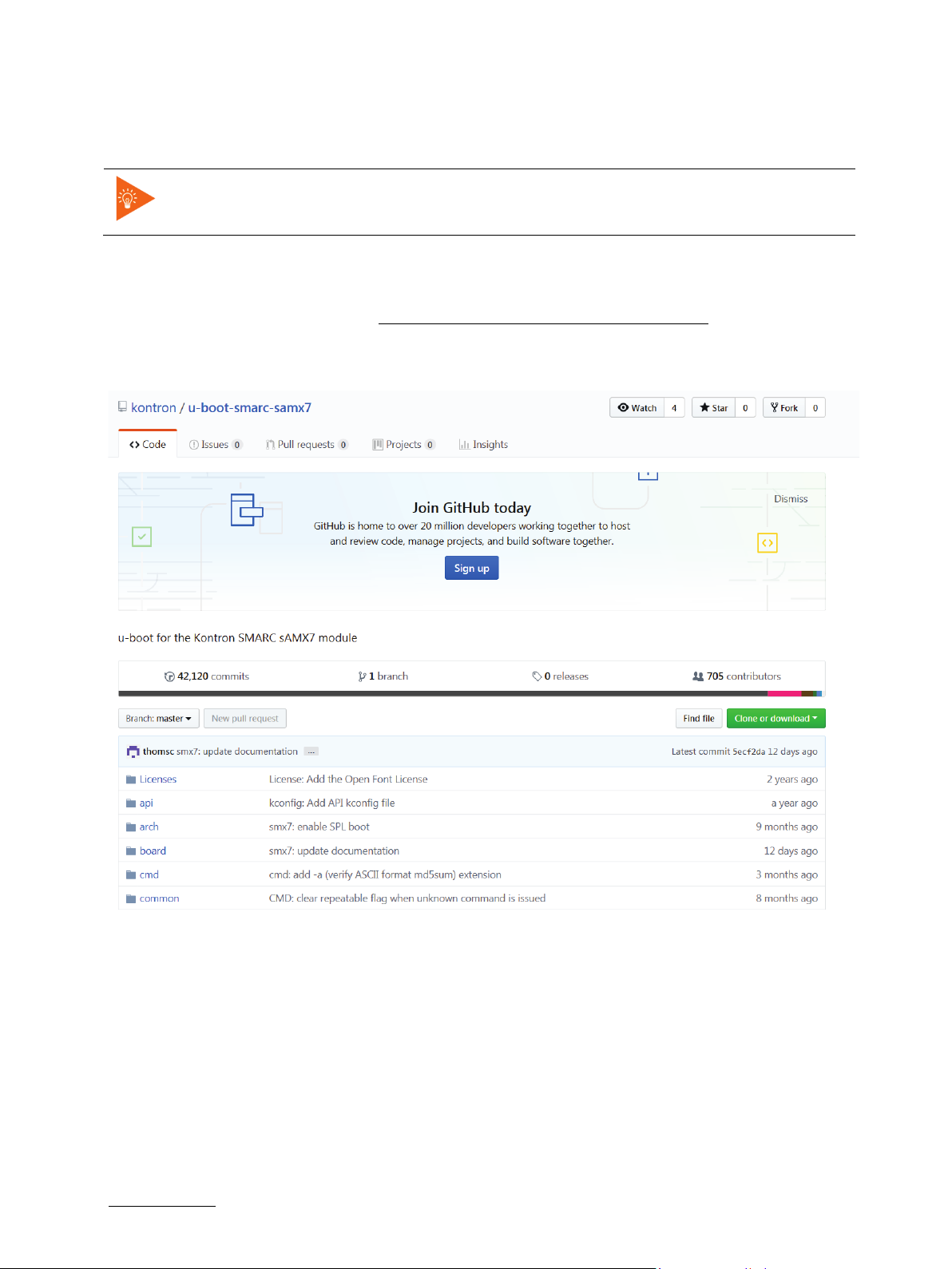
SMARC-sAMX7 User Guide. Rev. 1.5
Or, in case of network update
=> run updNet
It is recommended to use only the update script for bootloader update. This ensures that all
necessary installation images are checksum controlled and copied to the appropriate
location in QSPI flash.
7.13. U-boot Files for the Kontron SMARC sAMX7 Module on Github.com
You can find the last program code under https://github.com/kontron/u-boot-smarc-samx7.
Figure 9: 7.13. U-boot Files on Github.com
www.kontron.com // 55
Page 56

List of Acronyms
SMARC-sAMX7 User Guide. Rev. 1.5
CPLD Complex Programmable Logic Devices
CSI Camera Serial Interface
DTE Data Terminal Equipment
DSI Display Serial Interface
DCE Data Communications Equipment
eCSPI enhanced Configurable Synchronous Programmable
serial Interface
eCSPI enhanced Configurable Synchronous Programmable
serial Interface
eDP embedded Display Port
EMC Electromagnetic Compatibility
EMI Electromagnetic Interference
eMMC embedded Multimedia Card
EPDC Electronic Paper Display Controller
ESD Electrostatic Discharge
GPIO General-purpose input/output
HDA High Definition Audio
HDMI Integrated High Definition Multimedia Interface
I2S Inter-IC Sound
KPP Key Pad Port
LPDDR Low Power DDR
LVDS Low Voltage Differential Signalling
MIPI Mobile Industry Processor Interface
MLC Multi-level Cell
pSLC pseudo Single Level Cell
SDIO Secure Digital Input Output
SMARC Smart Mobility ARChitecture
SMBus System Management Bus
SoC System on Chip
TPM Trusted Platform Module
UART Universal Asynchronous Receiver Transmitter
www.kontron.com // 56
Page 57

SMARC-sAMX7 User Guide. Rev. 1.5
HEADQUARTERS
Kontron S&T AG
Lise
86156 Augsburg
Germany
Tel.: +
Fax: +
info@kontron.com
About Kontron
Kontron, a global leader in embedded computing technology and trusted advisor in Internet of Things (IoT), works
closely with its customers, allowing them to focus on their core competencies by offering a complete and integrated
portfolio of hardware, software and services designed to help them make the most of their applications.
With a significant percentage of employees in research and development, Kontron creates many of the standards
that drive the world’s embedded computing platforms; bringing to life numerous technologies and applications that
touch millions of lives. The result is an accelerated time-to-market, reduced total-cost-of-ownership, product
longevity and the best possible overall application with leading-edge, highest reliability embedded technology.
For more information, please visit: http://www.kontron.com/
-Meitner-Str. 3-5
49 821 4086-0
49 821 4086-111
www.kontron.com // 57
 Loading...