

Page 1
SMARC-sAMX6i
Document Revision 1.0
www.kontron.com
Page 2

Page 3

» Table of Contents «
1 User Information..................................................................................5
1.1 About This Document.................................................................................................................... 5
1.2 Copyright Notice.......................................................................................................................... 5
1.3 Trademarks................................................................................................................................. 5
1.4 Standards................................................................................................................................... 5
1.5 Warranty.................................................................................................................................... 6
1.6 Technical Support......................................................................................................................... 6
2 Introduction........................................................................................7
2.1 Product Description...................................................................................................................... 7
2.2 SMARC™ Computer-on-Modules....................................................................................................... 7
3 Product Specification............................................................................8
3.1 SMARC-sAMX6i Feature Set............................................................................................................. 8
3.2 Modules & Accessories................................................................................................................... 8
3.3 Functional Specification............................................................................................................... 10
3.4 Block Diagram............................................................................................................................ 13
3.5 Electrical Specification................................................................................................................ 14
3.5.1 Supply Voltage........................................................................................................................... 14
3.5.2 Power Supply Rise Time................................................................................................................ 14
3.5.3 Supply Voltage Ripple.................................................................................................................. 14
3.6 Power Control............................................................................................................................ 15
3.7 Power Consumption..................................................................................................................... 15
3.8 Environmental Specification......................................................................................................... 16
3.8.1 Temperature Specification............................................................................................................ 16
3.8.2 Humidity................................................................................................................................... 16
3.9 Standards and Certifications......................................................................................................... 17
3.10 MTBF........................................................................................................................................ 18
3.11 Mechanical Specification.............................................................................................................. 19
3.11.1 Module Dimension...................................................................................................................... 19
3.11.2 Height on Top............................................................................................................................ 19
3.11.3 Height on Bottom....................................................................................................................... 19
3.11.4 Mechanical Drawing.................................................................................................................... 19
3.11.5 Dimensions and mounting holes of SMARC-sAMX6..............................................................................20
4 Connectors........................................................................................21
4.1 SMARC™ Connector Top Side..........................................................................................................21
4.2 SMARC™ Connector Bottom Side..................................................................................................... 24
5 Bootloader Operation..........................................................................29
5.1 Copyrights and Licensing.............................................................................................................. 29
5.1.1 Obtaining Source Code................................................................................................................. 29
5.2 Introduction to U-Boot................................................................................................................ 29
www.kontron.com
Page 4

SMARC-sAMX6i /
5.3 Standard U-Boot Commands.......................................................................................................... 29
5.4 Kontron-Specific Commands......................................................................................................... 31
5.4.1 kboardinfo................................................................................................................................ 31
5.4.2 md5sum.................................................................................................................................... 31
5.5 U-Boot Access and Startup............................................................................................................ 32
5.6 Environment.............................................................................................................................. 32
5.7 Working with U-Boot................................................................................................................... 32
5.7.1 General Operation....................................................................................................................... 32
5.7.2 Using the Network...................................................................................................................... 32
5.7.3 Using SD Cards and onboard eMMC device........................................................................................ 33
5.8 Bootloader Update...................................................................................................................... 33
5.8.1 Downloading the bootloader.........................................................................................................33
5.8.2 Updating via TFTP Server.............................................................................................................. 33
5.8.3 Updating via USB Stick................................................................................................................. 34
5.9 Bootlogo.................................................................................................................................. 34
4
Page 5

SMARC-sAMX6i / User Information
1 User Information
1.1 About This Document
This document provides information about products from Kontron Europe GmbH and/or its subsidiaries. No warranty of
suitability, purpose, or fitness is implied. While every attempt has been made to ensure that the information in this
document is accurate, the information contained within is supplied “as-is” and is subject to change without notice.
For the circuits, descriptions and tables indicated, Kontron assumes no responsibility as far as patents or other rights of
third parties are concerned.
1.2 Copyright Notice
Copyright © 2003-2014 Kontron Europe GmbH
All rights reserved. No part of this document may be reproduced, transmitted, transcribed, stored in a retrieval system, or
translated into any language or computer language, in any form or by any means (electronic, mechanical, photocopying,
recording, or otherwise), without the express written permission of Kontron Europe GmbH.
DIMM-PC®, PISA®, ETX®, ETXexpress®, microETXexpress®, X-board®, DIMM-IO® and DIMM-BUS® are trademarks or
registered trademarks of Kontron Europe GmbH. Kontron is trademark or registered trademark of Kontron AG.
1.3 Trademarks
The following lists the trademarks of components used in this board.
» IBM, XT, AT, PS/2 and Personal System/2 are trademarks of International Business Machines Corp.
» Microsoft is a registered trademark of Microsoft Corp.
» Intel is a registered trademark of Intel Corp.
» All other products and trademarks mentioned in this manual are trademarks of their respective owners.
1.4 Standards
Kontron Europe GmbH is certified to ISO 9000 standards.
5
Page 6

SMARC-sAMX6i / User Information
1.5 Warranty
For this Kontron Europe GmbH product warranty for defects in material and workmanship exists as long as the warranty
period, beginning with the date of shipment, lasts. During the warranty period, Kontron Europe GmbH will decide on its
discretion if defective products are to be repaired or replaced.
Within the warranty period, the repair of products is free of charge as long as warranty conditions are observed.
Warranty does not apply for defects arising/resulting from improper or inadequate maintenance or handling by the buyer,
unauthorized modification or misuse, as well as the operation outside of the product´s environmental specifications and
improper installation and maintenance.
Kontron Europe GmbH will not be responsible for any defects or damages to other products not supplied by Kontron
Europe GmbH that are caused by a faulty Kontron Europe GmbH product.
1.6 Technical Support
Technicians and engineers from Kontron Europe GmbH and/or its subsidiaries are available for technical support. We are
committed to make our product easy to use and will help you use our products in your systems.
Please consult our Website at http://www.kontron.com/support for the latest product documentation, utilities, drivers
and support contacts. Consult our customer section http://emdcustomersection.kontron.com for the latest BIOS
downloads, Product Change Notifications, Board Support Packages, DemoImages, 3D drawings and additional tools and
software. In any case you can always contact your board supplier for technical support.
6
Page 7

SMARC-sAMX6i / Introduction
2 Introduction
2.1 Product Description
The small-sized SMARC™ Module with Freescale i.MX6 processor offers a wide range of processor scalability with single,
dual and quadcore processors. The X86 alike interfacing of SMARC-sAMX6i allows an easy integration in any kind of
application.
2.2 SMARC™ Computer-on-Modules
The SMARC™ standard was developed especially for new modules with ARM- and SOC-processors and is characterized by
the extremely flat build of its form factor. It is based on the MXM 3.0 connector with 314 pins and a construction height of
just 4.3 millimeters and it thus allows robust and flatly constructed designs with a cost-effective card edge connector. The
connector is also available in a shock- and vibration-resistant version for rough environmental conditions. Furthermore,
the standard integrates dedicated interfaces for the latest ARM and SOC processors which not only means LVDS, 24-bit
RGB and HDMI support but also support of embedded DisplayPort for future designs. In addition, and for the first time,
dedicated camera interfaces are being incorporated into a COM standard. OEMs profit from minimized design effort and
bill of material costs. SMARC™ defines two different module sizes in order to offer a high level of flexibility regarding
different mechanical requirements: a short modules measuring 82 mm x 50 mm and a full-size module measuring 82 mm x
80 mm.
SMARC™ is the low-power embedded architecture platform for computer-on-modules based on ARM technology.
» Creating mobile, embedded, connected solutions
» Scalable building blocks
» Optimized pin-out definition for ARM technology
» Ultra low-power, low-profile solutions
» Constructed to withstand harsh industrial environments
7
Page 8
SMARC-sAMX6i / Product Specification
3 Product Specification
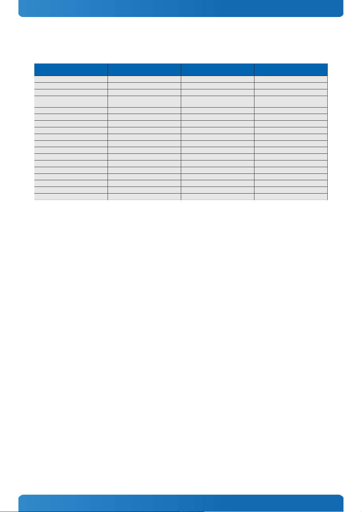
3.1 SMARC-sAMX6i Feature Set
SMARC™ Feature specification SMARC™ Specification Maximum
Number Possible
SMARC-sAMX6i Feature support SMARC-sAMX6i Featuresupport
instances
LVDS Display support 1 Yes 1
Parallel LCD support 1 Yes 1(24bit)
HDMI Display support 1 Yes 1
CSI Camera support (Dual and Quad
lanes)
2 Yes 1 (Quad lane)
Parallel Camera support 2 Yes 1
USB Interface 3 Yes 3
PCIe Interface 3 Yes 1 (3 PCIe lanes can be realised opionally)
SATA Interface 1 Yes 1 (0 on module with i.MX6 solo)
GbE Interface 1 Yes 1
SDIO Interface (4bit) 1 Yes 1 (max. 25MHz)
SDMMC Interface (8bit) 1 Yes 1 (max. 25MHz)
SPI Interface 2 Yes 2
I2S Interface 3 Yes 1
I2C Interface 5 Yes 5
CAN 2 Yes 2
AFB 1 Yes MLB150 is realised
I/O Voltage (1.8V) level support - Yes -
I/O Voltage (3.3V) level support - No -
8
Page 9
SMARC-sAMX6i / Product Specification
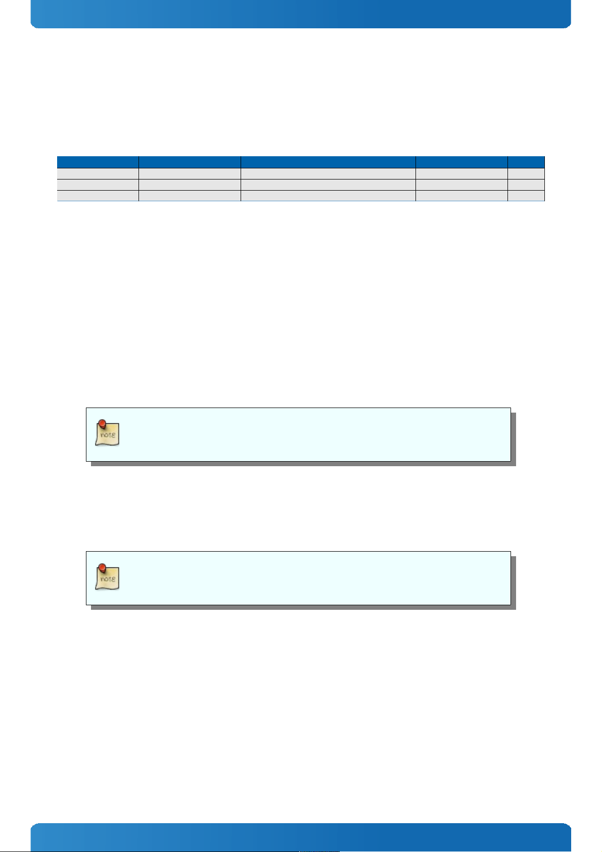
3.2 Modules & Accessories
The SMARC small sized Computer-on-Module SMARC-sAMX6i (SMX6) is compatible to SMARC V1.0. The SMARC-sAMX6i,
based on Freescale's iMX6 platform, is available in different variants to cover the demand of different performance, price
and power:
Part Number Product Name Processor DDR3 Flash SATA
51003-0540-08-1 SMARC-sAMX6i 0.8 512/4GB Freescale i.MX6 solo, 800MHz, industrial grade 512MB 4GB SLC -
51003-1040-08-2 SMARC-sAMX6i 2×0.8 1/4GB Freescale i.MX6 dual, 800MHz, industrial grade 1GB 4GB SLC YES
51003-1040-08-4 SMARC-sAMX6i 4×0.8 1/4GB Freescale i.MX6 quad, 800MHz, industrial grade 1GB 4GB SLC YES
Memory and onboard Flash configurations 51003-MMFF-xx-x:
» MM = 05: 512MB DDR3 Memory
» MM = 10: 1024MB DDR3 Memory
» MM = 20: 2048MB DDR3 Memory
» FF = 00: without onboard eMMC
» FF = 40: 4GB onboard eMMC (SLC)
» FF = 80: 8GB onboard eMMC (SLC)
» FF = 16: 16GB onboard eMMC (SLC)
» FF = 32: 32GB onboard eMMC (SLC)
On request we can also offer MLC eMMC flash devices
Optional hardware features:
» 3 PCIe instead of 1 lane
» 3 I2S instead of 1 I2S, but then with only 16bit parallel LCD interface instead of 24bit
» any other available pin compatible Freescale i.MX6 processor can be mounted
Optional hardware and firmware features are available project based only for variants not
listed above. Please contact your local sales for customized articles.
9
Page 10

SMARC-sAMX6i / Product Specification
Accessories
Product Number Carrier Boards
51000-0000-00-0 SMARC Evaluation Carrier
51000-0000-00-S SMARC Starter Kit
Product Number Cooling & Mounting
51003-0000-99-1 HSP SMARC-sAMX6 full size
Product Number Adapter & Cables
TBD TBD
10
Page 11
SMARC-sAMX6i / Product Specification
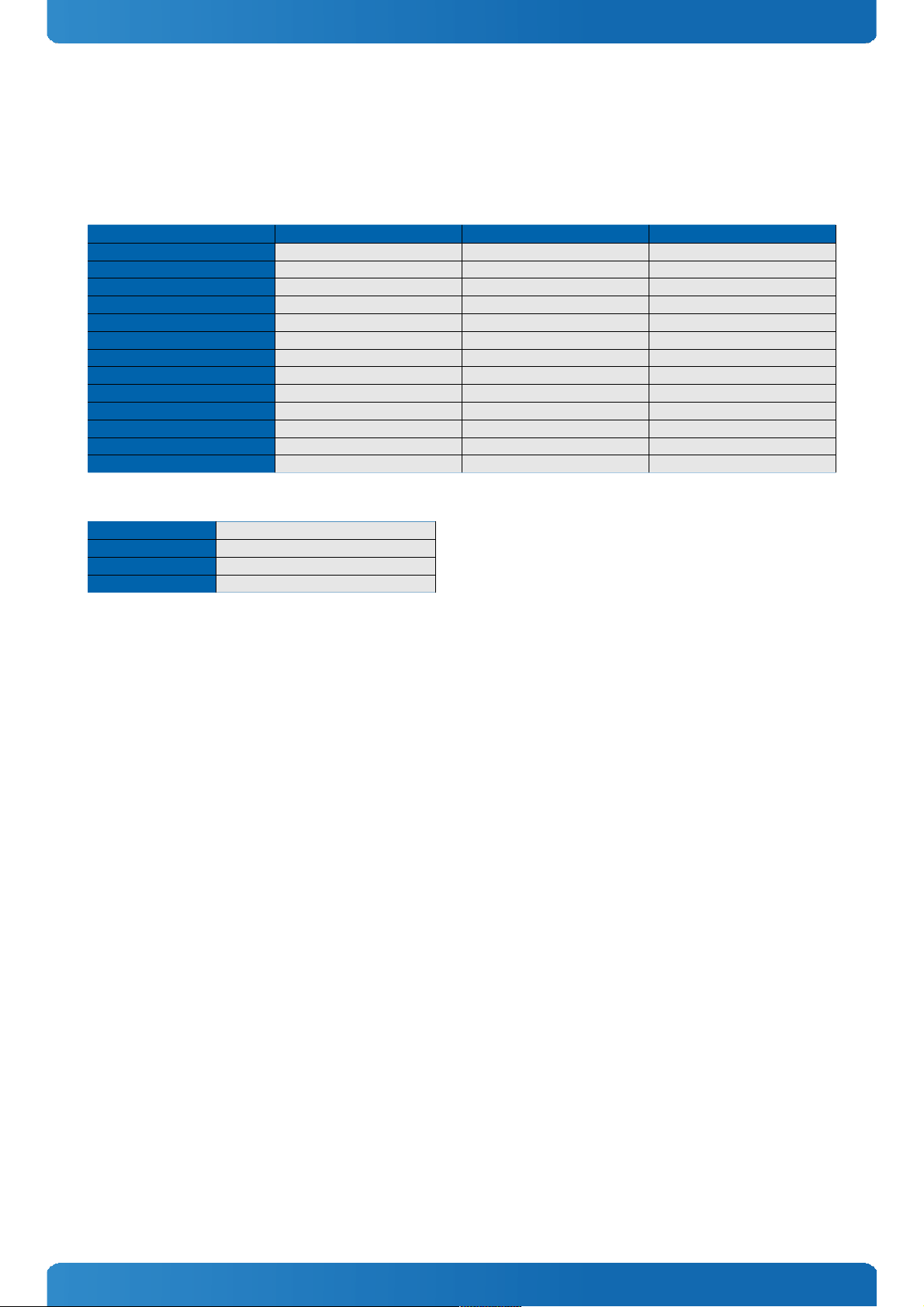
3.3 Functional Specification
Processor
CPU specifications
CPU Freescale i.MX6 solo Freescale i.MX6 dual Freescale i.MX6 quad
Cores
1 2 2
Clock
800MHz 800MHz 800MHz
Memory Speed
DDR3-533 DDR3-533 DDR3-533
Max Memory
up to 1GB up to 2GB up to 2GB
Cache
512KB L2 1MB L2 + VFPv3 1MB L2 + VFPv3
GFX
Vivante Vivante Vivante
GFX core frequency
528MHz 528MHz 528MHz
IPUs (Image Processing Units)
1 2 2
LVDS
1×18/24bit 1×18/24bit 1×18/24bit
LVDS Resolution
up to 1366x768x60 up to 1366x768x60 up to 1366x768x60
Parallel LCD Resolution
up to TBD up to 1920x1080x60 up to 1920x1080x60
HDMI Resolution
up to TBD up to 1920x1200x60 up to 1920x1200x60
Independent Display Support
- yes yes
Memory
Sockets
memory down
Memory Type
DDR3
Maximum Size
2GB (1GB for Solo)
Technology
Single Channel (64bit) (32bit for Solo)
11
Page 12
SMARC-sAMX6i / Product Specification
Graphics Core
The integrated Vivante core based supports:
3D Graphics Core
Vivante GC2000
Shader Cores
4 with 21.6 GFLOP
2D Core
Vivante GC320
2D Performance
633M pixels / sec raw performance
Vector Graphics Core
Vivate GC355
Maximum Resolution (total)
4096x4096
Maximum Pixel Rate
266 MP/s
API (DirectX/OpenGL)
OpenGL, OpenCL
Hardware accelerated Video
TBD
Independent/Simultaneous Displays
2
HDCP support
optional (HDCP 1.4)
LVDS
LVDS max Resolution:
WXGA @60Hz
PWM Backlight Control:
YES
Supported Panel Data:
TBD
Display Interfaces
Parallel Display Bits
24
Parallel Display Max. Resolution
WUXGA @60Hz (?)
HDMI
Max Resolution HDMI
1080p @ 60Hz
HDMI version
HDMI 1.4a
HDCP support
optional (HDCP 1.4)
Storage
onboard SSD
1x eMMC up to 64GB (MLC), 32GB
(SLC)
SD Card / eMMC support
SDIO support via carrier board
Serial-ATA
1x SATA 3.0GB/s (only Quad/Dual)
SATA AHCI
?
SATA is not available on modules with i.MX6 solo processor.
Connectivity
USB
3x USB 2.0
PCI Express
1x PCIe x1 Gen2
Max PCI Express
1x PCIe standard (3x optional with
brige)
Ethernet
10/100/1000 Mbit
Ethernet controller
processor integrated (with
Broadcom Phy)
Ethernet
The ethernet controller is in the processor integrated (with Broadcom Phy) and supports supports:
» Jumbo Frames TBD
» Time Sync Protocol Indicator TBD
» PXE (Preboot eXecution Environment)
12
Page 13

SMARC-sAMX6i / Product Specification
AFB Section
AFB Interface 1
MLB150
Misc Interfaces and Features
Audio
I2S interface
Miscellaneous
-
External I2C Bus
5x Fast I2C
Watchdog support
Single Staged
Power Features
Singly Supply Support
YES
Supply Voltage
3.0-5,25V
Misc Power Management
-
Power Consumption and Performance
Full Load Power Consumption
TBD
Supported Operating Systems
The SMARC-sAMX6i supports:
» Linux
» Android
» Microsoft Windows Embedded Compact 7 (WEC7)
13
Page 14

SMARC-sAMX6i / Product Specification
3.4 Block Diagram
14
Page 15

SMARC-sAMX6i / Product Specification
3.5 Electrical Specification
3.5.1 Supply Voltage
Following supply voltage is specified at the SMARC™ connector:
VCC:
3.0-5,25V
RTC:
2.5V - 3.3V
3.5.2 Power Supply Rise Time
» The input voltages shall rise from ≤10% of nominal to within the regulation ranges within 0.1ms to 20ms.
» There must be a smooth and continuous ramp of each DC input voltage from 10% to 90% of its final set-point
3.5.3 Supply Voltage Ripple
» Maximum 100 mV peak to peak 0 – 20 MHz
15
Page 16

SMARC-sAMX6i / Product Specification
3.6 Power Control
Power Supply
The SMARC-sAMX6i supports a power input from 3.0-5,25V. The supply voltage is applied through the VCC pins (VCC) of the
module connector.
Power Button (PWR_BTN#)
The power button (Pin P128) is available through the module connector described in the pinout list. To start the module
via Power Button the PWRBTN# signal must be at least 50ms (50ms ≤ t < 4s, typical 400ms) at low level (Power Button
Event).
Pressing the power button for at least 4seconds will turn off power to the module (Power Button Override).
CB_POWER_BAD#
The SMARC-sAMX6i provides an external input for a Carrier Board Power Bad signal (Pin S150). The implementation of this
subsystem complies with the COM Express® Specification. CB_POWER_BAD# is internally pulled up to 3.3V and must be
high level to power on the module.
Reset Button (RST_CB_IN#)
The reset button (Pin P127) is available through the module connector described in the pinout list. The module will stay in
reset as long as RST_CB_IN# is grounded.
3.7 Power Consumption
Following data provides power consumption measurements of single modules with i.MX6 solo (51003-0540-08-1) and
i.MX6 quad (51003-1040-08-4).
processor linux shell mem test
i.MX6 solo 2.46W 3.47W
i.MX6 quad 2.87W 4.52W
This might not be the maximum load a module can have, but due to the lack of standardized stress test software for ARM
processors this data cannot be provided.
16
Page 17

SMARC-sAMX6i / Product Specification
3.8 Environmental Specification
3.8.1 Temperature Specification
General Specification Operating Non-operating
Commercial grade 0°C to +60°C -30°C to +85°C
Extended (E1) -25°C to +75°C -30°C to +85°C
Industrial grade (E2) -40°C to +85°C -40°C to +85°C
Standard modules are available for industrial grade temperature range. Please see chapter
Product Specification for available variants for extended or commercial temperate grade
With Kontron heatspreader plate assembly
The operating temperature defines two requirements:
» the maximum ambient temperature with ambient being the air surrounding the module.
» the maximum measurable temperature on any spot on the heatspreader's surface
Without Kontron heatspreader plate assembly
The operating temperature is the maximum measurable temperature on any spot on the module's surface.
3.8.2 Humidity
» Operating: 10% to 90% (non condensing)
» Non operating: 5% to 95% (non condensing)
17
Page 18

SMARC-sAMX6i / Product Specification
3.9 Standards and Certifications
RoHS
The SMARC-sAMX6i
is compliant to the directive 2002/95/EC on the restriction of the use of certain hazardous substances (RoHS) in electrical
and electronic equipment.
CE marking
The SMARC-sAMX6i
is CE marked according to Low Voltage Directive 2006/95/EC – Test standard EN60950
WEEE Directive
WEEE Directive 2002/96/EC is not applicable for Computer-on-Modules.
Conformal Coating
Conformal Coating is available for Kontron Computer-on-Modules and for validated SO-DIMM memory modules. Please
contact your local sales or support for further details.
EMC
Validated in Kontron reference housing for EMC the SMARC-sAMX6i follows the requirements for electromagnetic
compatibility standards
» EN55022
18
Page 19

SMARC-sAMX6i / Product Specification
3.10 MTBF
The following MTBF (Mean Time Before Failure) values were calculated using a combination of manufacturer’s test data, if
the data was available, and the Telcordia (Bellcore) issue 2 calculation for the remaining parts.
The calculation method used is “Telcordia Method 1 Case 3” in a ground benign, controlled environment (GB,GC). This
particular method takes into account varying temperature and stress data and the system is assumed to have not been
burned in.
Other environmental stresses (extreme altitude, vibration, salt water exposure, etc) lower MTBF values.
System MTBF (hours): 209423 @ 40°C
Fans usually shipped with Kontron Europe GmbH products have 50,000-hour typical
operating life. The above estimates assume no fan, but a passive heat sinking arrangement
Estimated RTC battery life (as opposed to battery failures) is not accounted for in the above
figures and need to be considered separately. Battery life depends on both temperature
and operating conditions. When the Kontron unit has external power; the only battery
drain is from leakage paths.
19
Page 20

SMARC-sAMX6i / Product Specification
3.11 Mechanical Specification
3.11.1 Module Dimension
» 50mm x 82mm
3.11.2 Height on Top
» Maximum 3.0mm (without printed circuit board)
» Height is depending on (optional) CPU cooler / heat spreader
3.11.3 Height on Bottom
» Maximum approx. 1.3mm (without printed circuit board)
3.11.4 Mechanical Drawing
All dimensions are shown in millimeters. Tolerances should be ± 0.25mm [±0.010”], unless otherwise noted.
CAD drawings will be available at EMD CustomerSection
20
Page 21

SMARC-sAMX6i / Product Specification
3.11.5 Dimensions and mounting holes of SMARC-sAMX6
21
Page 22

SMARC-sAMX6i / Connectors
4 Connectors
The pinouts for Interface Connector are documented for convenient reference. Please see the SMARC Specification and
SMARC Design Guide for detailed, design-level information.
4.1 SMARC™ Connector Top Side
Pin Signal Module
Direction
Module
Termination
Type/Tolerance Controller Controller
Pin Name
Port(i.MX6
Quad/Dual)
Port(i.MX6
Solo)
I/O MUX
Instance
Quad/Solo
Power Rail
P1 PCAM_PXL_CK1 In - CMOS / VDD_IO - - N.C. N.C. - -
P2 GND - - - - - - - - -
P3 CSI1_CK+ / PCAM_D0 In - LVDS D-PHY / VDD_IO iMX6 EIM_A17 IPU2_CSI1_
DATA12
GPIO2_IO21 (*1) ALT2 / ALT5 V_VIO_S0
P4 CSI1_CK- / PCAM_D1 In - LVDS D-PHY / VDD_IO iMX6 EIM_A18 IPU2_CSI1_
DATA13
GPIO2_IO20 (*1) ALT2 / ALT5 V_VIO_S0
P5 PCAM_DE In - CMOS / VDD_IO iMX6 EIM_D23 IPU2_CSI1_
DATA_EN
GPIO3_IO23 (*1) ALT2 / ALT5 V_VIO_S0
P6 PCAM_MCK Out - CMOS / VDD_IO iMX6 GPIO_3 CCM_CLKO2 CCM_CLKO2 ALT4 / ALT4 V_VIO_S0
P7 CSI1_D0+ / PCAM_D2 In - LVDS D-PHY / VDD_IO iMX6 EIM_A19 IPU2_CSI1_
DATA14
GPIO2_IO19 (*1) ALT2 / ALT5 V_VIO_S0
P8 CSI1_D0- / PCAM_D3 In - LVDS D-PHY / VDD_IO iMX6 EIM_A20 IPU2_CSI1_
DATA15
GPIO2_IO18 (*1) ALT2 / ALT5 V_VIO_S0
P9 GND - - - - - - - - -
P10 CSI1_D1+ / PCAM_D4 In - LVDS D-PHY / VDD_IO iMX6 EIM_A21 IPU2_CSI1_
DATA16
GPIO2_IO17 (*1) ALT2 / ALT5 V_VIO_S0
P11 CSI1_D1- / PCAM_D5 In - LVDS D-PHY / VDD_IO iMX6 EIM_A22 IPU2_CSI1_
DATA17
GPIO2_IO16 (*1) ALT2 / ALT5 V_VIO_S0
P12 GND - - - - - - - - -
P13 CSI1_D2+ / PCAM_D6 In - LVDS D-PHY / VDD_IO iMX6 EIM_A23 IPU2_CSI1_
DATA18
GPIO6_IO06 (*1) ALT2 / ALT5 V_VIO_S0
P14 CSI1_D2- / PCAM_D7 In - LVDS D-PHY / VDD_IO iMX6 EIM_A24 IPU2_CSI1_
DATA19
GPIO5_IO04 (*1) ALT2 / ALT5 V_VIO_S0
P15 GND - - - - - - - - -
P16 CSI1_D3+ / PCAM_D8 IN - LVDS D-PHY / VDD_IO - - N.C. N.C. - -
P17 CSI1_D3- / PCAM_D9 IN - LVDS D-PHY / VDD_IO - - N.C. N.C. - -
P18 GND - - - - - - - - -
P19 GBE_MDI3- Bi-Dir - GBE MDI BCM54610 TRD3M RGMII RGMII - -
P20 GBE_MDI3+ Bi-Dir - GBE MDI BCM54610 TRD3P RGMII RGMII - -
P21 GBE_LINK100# Out / OD - VDD_IO BCM54610
/ CPLD
- RGMII RGMII - -
P22 GBE_LINK1000# Out / OD - VDD_IO BCM54610
/ CPLD
- RGMII RGMII - -
P23 GBE_MDI2- Bi-Dir - GBE MDI BCM54610 TRD2M RGMII RGMII - -
P24 GBE_MDI2+ Bi-Dir - GBE MDI BCM54610 TRD2P RGMII RGMII - -
P25 GBE_LINK_ACT# Out / OD - VDD_IO BCM54610
/ CPLD
- RGMII RGMII - -
P26 GBE_MDI1- Bi-Dir - GBE MDI BCM54610 TRD1M RGMII RGMII - -
P27 GBE_MDI1+ Bi-Dir - GBE MDI BCM54610 TRD1P RGMII RGMII - -
P28 GBE_CTREF Out - V-Ref 100nF to
GND
- RGMII RGMII - -
P29 GBE_MDI0- Bi-Dir - GBE MDI BCM54610 TRD0M RGMII RGMII - -
P30 GBE_MDI0+ Bi-Dir - GBE MDI BCM54610 TRD0P RGMII RGMII - -
P31 SPI0_CS1# Out - CMOS / VDD_IO iMX6 EIM_D25 ECSPI4_SS3 - ALT1 / ALT1 V_VIO_S0
P32 GND - - - - - - - - -
P33 SDIO_WP In W-PU CMOS 3.3V iMX6 ENET_RXD1 GPIO1_IO26 GPIO1_IO26 ALT5 / ALT5 V_3V3_S0
P34 SDIO_CMD Bi-Dir PU-10k CMOS 3.3V iMX6 SD3_CMD SD3_CMD SD3_CMD ALT0 / ALT0 V_3V3_S0
P35 SDIO_CD# In PU-10k CMOS 3.3V iMX6 NANDF_CS1GPIO6_IO14 GPIO6_IO14 ALT5 / ALT5 V_1V8_S0
P36 SDIO_CK Out - CMOS 3.3V iMX6 SD3_CLK SD3_CLK SD3_CLK ALT0 / ALT0 V_3V3_S0
P37 SDIO_PWR_EN Out - CMOS 3.3V iMX6 ENET_TXD1 GPIO1_IO29 GPIO1_IO29 ALT5 / ALT5 V_3V3_S0
P38 GND - - - - - - - - -
P39 SDIO_D0 Bi-Dir - CMOS 3.3V iMX6 SD3_DAT0 SD3_DATA0 SD3_DATA0 ALT0 / ALT0 V_3V3_S0
P40 SDIO_D1 Bi-Dir - CMOS 3.3V iMX6 SD3_DAT1 SD3_DATA1 SD3_DATA1 ALT0 / ALT0 V_3V3_S0
P41 SDIO_D2 Bi-Dir - CMOS 3.3V iMX6 SD3_DAT2 SD3_DATA2 SD3_DATA2 ALT0 / ALT0 V_3V3_S0
P42 SDIO_D3 Bi-Dir PD-300k CMOS 3.3V iMX6 SD3_DAT3 SD3_DATA3 SD3_DATA3 ALT0 / ALT0 V_3V3_S0
P43 SPI0_CS0# Out - CMOS / VDD_IO CPLD - - - - V_VIO_S5
- - - - - iMX6 EIM_D29 ECSPI4_SS0 ECSPI4_SS0 ALT2 / ALT2 V_VIO_S0
- - - - - iMX6 EIM_D24 ECSPI4_SS2 ECSPI4_SS2 ALT1 / ALT1 V_VIO_S0
P44 SPI0_CK Out Serial 20R CMOS / VDD_IO iMX6 EIM_D21 ECSPI4_SCLK ECSPI4_SCLK ALT1 / ALT1 V_VIO_S0
P45 SPI0_DIN In Ser ial 0R CMOS / VDD_IO iMX6 EIM_D22 ECSPI4_MIS ECSPI4_MISO ALT1 / ALT1 V_VIO_S0
22
Page 23

SMARC-sAMX6i / Connectors
O
P46 SPI0_DO Out Serial 20R CMOS / VDD_IO iMX6 EIM_D28 ECSPI4_MOSIECSPI4_MOSI ALT2 / ALT2 V_VIO_S0
P47 GND - - - - - - - - -
P48 SATA_TX+ Out Serial 10nF SATA iMX6 SATA_TXP - - - -
P49 SATA_TX- Out Serial 10nF SATA iMX6 SATA_TXM - - - -
P50 GND - - - - - - - - -
P51 SATA_RX+ In - SATA iMX6 SATA_RXP - - - -
P52 SATA_RX- In - SATA iMX6 SATA_RXM - - - -
P53 GND - - - - - - - - -
P54 SPI1_CS0# Out - CMOS / VDD_IO iMX6 EIM_RW ECSPI2_SS0 ECSPI2_SS0 ALT2 / ALT2 V_VIO_S0
P55 SPI1_CS1# Out - CMOS / VDD_IO iMX6 EIM_LBA ECSPI2_SS1 ECSPI2_SS1 ALT2 / ALT2 V_VIO_S0
P56 SPI1_CK Out - CMOS / VDD_IO iMX6 EIM_CS0 ECSPI2_SCLK ECSPI2_SCLK ALT2 / ALT2 V_VIO_S0
P57 SPI1_DIN In - CMOS / VDD_IO iMX6 EIM_OE ECSPI2_MISOECSPI2_MISO ALT2 / ALT2 V_VIO_S0
P58 SPI1_DO Out - CMOS / VDD_IO iMX6 EIM_CS1 ECSPI2_MOSIECSPI2_MOSI ALT2 / ALT2 V_VIO_S0
P59 GND - - - - - - - - -
P60 USB0+ Bi-Dir - USB iMX6 USB_OTG_DP- - - -
P61 USB0- Bi-Dir - USB iMX6 USB_OTG_DN- - - -
P62 USB0_EN_OC# Bi-Dir / ODPU-10k CMOS 3.3V - - - - - -
- - - - - iMX6 CSI0_DATA
_EN
GPIO5_IO20 GPIO5_IO20 ALT5 / ALT5 V_VIO_S0
- - - - - iMX6 CSI0_PIXCLKGPIO5_IO18 GPIO5_IO18 ALT5 / ALT5 V_VIO_S0
P63 USB0_VBUS_DET In PD-10k CMOS 3.3V Switch-
3.3V
- - - - -
P64 USB0_OTG_ID In PD-100k CMOS 3.3V iMX6 GPIO_1 GPIO1_IO01 GPIO1_IO01 ALT5 / ALT5 V_VIO_S0
P65 USB1+ Bi-Dir - USB - - - - - -
- - - - - iMX6 USB_H1_DP- - - -
- - - - - USB2512 USB_HUB1_+- - - -
P66 USB1- Bi-Dir - USB - - - - - -
- - - - - iMX6 USB_H1_DN- - - -
- - - - - USB2512 USB_HUB1_-- - - -
P67 USB1_EN_OC# Bi-Dir PU-10k CMOS 3.3V - - - - - -
- - - Serial-0R - USB2512 OCS1# - - - -
- - - Serial-330R - USB2512 PRTPWR1 - - - -
- - - Serial-0R - iMX6 EIM_D30 USB_H1_OC USB_H1_OC ALT6 / ALT6 V_VIO_S0
- - - Serial-330R - iMX6 EIM_D31 USB_H1_PWRUSB_H1_PWR ALT6 / ALT6 V_VIO_S0
P68 GND - - - - - - - - -
P69 USB2+ - - USB - - - - - -
P70 USB2- - - USB - - - - - -
P71 USB2_EN_OC# - PU-10k CMOS 3.3V - - - - - -
- - - Serial-0R - USB2512 OCS1# - - - -
- - - Serial-330R - USB2512 PRTPWR1 - - - -
P72 PCIE_C_PRSNT# In PU-39k CMOS 3.3V iMX6 EIM_A16 GPIO2_IO22 GPIO2_IO22 ALT5 / ALT5 V_VIO_S0
P73 PCIE_B_PRSNT# In PU-39k CMOS 3.3V iMX6 EIM_D16 GPIO3_IO16 GPIO3_IO16 ALT5 / ALT5 V_VIO_S0
P74 PCIE_A_PRSNT# In PU-39k CMOS 3.3V iMX6 EIM_D18 GPIO3_IO18 GPIO3_IO18 ALT5 / ALT5 V_VIO_S0
- <Key> - - - - - - - - -
P75 PCIE_A_RST# Out - CMOS 3.3V CPLD - - - - V_3V3_S5
- - - - - iMX6 EIM_DA13 GPIO3_IO13 GPIO3_IO13 ALT5 / ALT5 V_VIO_S0
P76 PCIE_C_CKREQ# In PU-39k CMOS 3.3V iMX6 EIM_BCLK GPIO6_IO31 GPIO6_IO31 ALT5 / ALT5 V_VIO_S0
P77 PCIE_B_CKREQ# In PU-39k CMOS 3.3V iMX6 EIM_EB0 GPIO2_IO28 GPIO2_IO28 ALT5 / ALT5 V_VIO_S0
P78 PCIE_A_CKREQ# In PU-39k CMOS 3.3V iMX6 EIM_EB1 GPIO2_IO29 GPIO2_IO29 ALT5 / ALT5 V_VIO_S0
P79 GND - - - - - - - - -
P80 PCIE_C_REFCK+ Out - LVDS PCIe PEX8605 PEX_REFCL
K_OUT+3
- - - -
P81 PCIE_C_REFCK- Out - LVDS PCIe PEX8605 PEX_REFCL
K_OUT-3
- - - -
P82 GND - - - - - - - - -
P83 PCIE_A_REFCK+ Out Seriell-100n LVDS PCIe - - - - - -
- - - - - PEX8605 PEX_REFCL
K_OUT+1
- - - -
- - - - - iMX6 CLK1+ - - - -
P84 PCIE_A_REFCK- Out Seriell-100n LVDS PCIe - - - - - -
23
Page 24

SMARC-sAMX6i / Connectors
- - - - - PEX8605 PEX_REFCL
K_OUT-1
- - - -
- - - - - iMX6 CLK1- - - - -
P85 GND - - - - - - - - -
P86 PCIE_A_RX+ In Serial-0R LVDS PCIe - - - - - -
- - - - - PEX8605 PEX_PER+[1]- - - -
- - - - - iMX6 PCIE_RXP - - - -
P87 PCIE_A_RX- In Serial-0R LVDS PCIe - - - - - -
- - - - - PEX8605 PEX_PER[1]
- - - -
- - - - - iMX6 PCIE_RXM - - - -
P88 GND - - - - - - - - -
P89 PCIE_A_TX+ Out Ser iell-100n LVDS PCIe - - - - - -
- - - - - PEX8605 PEX_PET+[1]- - - -
- - - - - iMX6 PCIE_TXP - - - -
P90 PCIE_A_TX- Out Seriell-100n LVDS PCIe - - - - - -
- - - - - PEX8605 PEX_PET[1]
- - - -
- - - - - iMX6 PCIE_TXM - - - -
P91 GND - - - - - - - - -
P92 HDMI_D2+ Out - TMDS iMX6 HDMI_D2P - - - -
P93 HDMI_D2- Out - TMDS iMX6 HDMI_D2M - - - -
P94 GND - - - - - - - - -
P95 HDMI_D1+ Out - TMDS iMX6 HDMI_D1P - - - -
P96 HDMI_D1- Out - TMDS iMX6 HDMI_D1M - - - -
P97 GND - - - - - - - - -
P98 HDMI_D0+ Out - TMDS iMX6 HDMI_D0P - - - -
P99 HDMI_D0- Out - TMDS iMX6 HDMI_D0M - - - -
P100 GND - - - - - - - - -
P101 HDMI_CK+ Out - TMDS iMX6 HDMI_CLKP- - - -
P102 HDMI_CK- Out - TMDS iMX6 HDMI_CLKM- - - -
P103 GND - - - - - - - - -
P104 HDMI_HPD In PU-39k CMOS / VDD_IO iMX6 HDMI_HPD - - - -
P105 HDMI_CTRL_CK Out PU-100k CMOS / VDD_IO iMX6 KEY_COL3 I2C2_SCL I2C2_SCL ALT4 / ALT4 V_VIO_S0
P106 HDMI_CTRL_DAT Bi-Dir PU-100k CMOS / VDD_IO iMX6 KEY_ROW3 I2C2_SDA I2C2_SDA ALT4 / ALT4 V_VIO_S0
- - Bi-Dir PU-100k CMOS / VDD_IO iMX6 HDMI_DDC
CEC
- - - -
P107 HDMI_CEC - - - iMX6 EIM_A25 HDMI_TX_CE
C_LINE
HDMI_TX_CEC_LINEALT6 / ALT6 -
P108 GPIO0 / CAM0_PWR# Bi-Dir PU-470k CMOS / VDD_IO iMX6 EIM_DA0 GPIO3_IO00 GPIO3_IO00 ALT5 / ALT5 V_VIO_S0
P109 GPIO1 / CAM1_PWR# Bi-Dir PU-470k CMOS / VDD_IO iMX6 EIM_DA1 GPIO3_IO01 GPIO3_IO01 ALT5 / ALT5 V_VIO_S0
P110 GPIO2 / CAM0_RST# Bi-Dir PU-470k CMOS / VDD_IO iMX6 EIM_DA2 GPIO3_IO02 GPIO3_IO02 ALT5 / ALT5 V_VIO_S0
P111 GPIO3 / CAM1_RST# Bi-Dir PU-470k CMOS / VDD_IO iMX6 EIM_DA3 GPIO3_IO03 GPIO3_IO03 ALT5 / ALT5 V_VIO_S0
P112 GPIO4 / HDA_RST# Bi-Dir PU-470k CMOS / VDD_IO iMX6 EIM_DA4 GPIO3_IO04 GPIO3_IO04 ALT5 / ALT5 V_VIO_S0
P113 GPIO5 / PWM_OUT Bi-Dir PU-470k CMOS / VDD_IO iMX6 EIM_DA5 GPIO3_IO05 GPIO3_IO05 ALT5 / ALT5 V_VIO_S0
P114 GPIO6 / TACHIN Bi-Dir PU-470k CMOS / VDD_IO iMX6 EIM_DA6 GPIO3_IO06 GPIO3_IO06 ALT5 / ALT5 V_VIO_S0
P115 GPIO7 / PCAM_FLD Bi-Dir PU-470k CMOS / VDD_IO iMX6 EIM_DA7 GPIO3_IO07 GPIO3_IO07 ALT5 / ALT5 V_VIO_S0
P116 GPIO8 / CAN0_ERR # Bi-Dir PU-470k CMOS / VDD_IO iMX6 EIM_DA8 GPIO3_IO08 GPIO3_IO08 ALT5 / ALT5 V_VIO_S0
P117 GPIO9 / CAN1_ERR # Bi-Dir PU-470k CMOS / VDD_IO iMX6 EIM_DA9 GPIO3_IO09 GPIO3_IO09 ALT5 / ALT5 V_VIO_S0
P118 GPIO10 Bi-Dir PU-470k CMOS / VDD_IO iMX6 EIM_DA10 GPIO3_IO10 GPIO3_IO10 ALT5 / ALT5 V_VIO_S0
P119 GPIO11 Bi-Dir PU-470k CMOS / VDD_IO iMX6 EIM_DA11 GPIO3_IO11 GPIO3_IO11 ALT5 / ALT5 V_VIO_S0
P120 GND - - - - - - - - -
P121 I2C_PM_CK Out PU-2k2 CMOS 1.8V iMX6 GPIO_5 I2C3_SCL I2C3_SCL ALT6 / ALT6 V_VIO_S0
P122 I2C_PM_DAT Bi-Dir PU-2k2 CMOS 1.8V iMX6 GPIO_16 I2C3_SDA I2C3_SDA ALT6 / ALT6 V_VIO_S0
P123 BOOT_SEL0# In W-PU CMOS / VDD_IO CPLD - - - - V_VIO_S5
P124 BOOT_SEL1# In W-PU CMOS / VDD_IO CPLD - - - - V_VIO_S5
P125 BOOT_SEL2# In W-PU CMOS / VDD_IO CPLD - - - - V_VIO_S5
P126 RESET_OUT# Out -OD - CMOS / VDD_IO CPLD - - - - V_VIO_S5
P127 RESET_IN# In W-PU CMOS / VDD_IO CPLD - - - - V_VIO_S5
P128 POWER_BTN# In - CMOS / VDD_IO CPLD - - - - V_VIO_S5
- - In W-PU CMOS / VDD_IO iMX6 NANDF_CS3GPIO6_IO16 GPIO6_IO16 ALT5 / ALT5 V_1V8_S0
P129 SER0_TX Out - CMOS / VDD_IO iMX6 CSI0_DAT10UART1_TX_D
ATA
UART1_TX_DATA ALT3 / ALT3 V_VIO_S0
P130 SER0_RX In W-PU CMOS / VDD_IO iMX6 CSI0_DAT11UART1_RX_D
ATA
UART1_RX_DATA ALT3 / ALT3 V_VIO_S0
P131 SER0_RTS# Out - CMOS / VDD_IO iMX6 EIM_D19 UART1_CTS_BUART1_CTS_B ALT4 / ALT4 V_VIO_S0
24
Page 25

SMARC-sAMX6i / Connectors
P132 SER0_CTS# In W-PU CMOS / VDD_IO iMX6 EIM_D20 UART1_RTS_BUART1_RTS_B ALT4 / ALT4 V_VIO_S0
P133 GND - - - - - - - - -
P134 SER1_TX Out - CMOS / VDD_IO iMX6 EIM_D26 UART2_TX_D
ATA
UART2_TX_DATA ALT4 / ALT4 V_VIO_S0
P135 SER1_RX In W-PU CMOS / VDD_IO iMX6 EIM_D27 UART2_RX_D
ATA
UART2_RX_DATA ALT4 / ALT4 V_VIO_S0
P136 SER2_TX Out - CMOS / VDD_IO iMX6 CSI0_DAT12UART4_TX_D
ATA
UART4_TX_DATA ALT3 / ALT3 V_VIO_S0
P137 SER2_RX In W-PU CMOS / VDD_IO iMX6 CSI0_DAT13UART4_RX_D
ATA
UART4_RX_DATA ALT3 / ALT3 V_VIO_S0
P138 SER2_RTS# Out - CMOS / VDD_IO iMX6 CSI0_DAT17UART4_CTS_BUART4_CTS_B ALT3 / ALT3 V_VIO_S0
P139 SER2_CTS# In W-PU CMOS / VDD_IO iMX6 CSI0_DAT16UART4_RTS_BUART4_RTS_B ALT3 / ALT3 V_VIO_S0
P140 SER3_TX Out - CMOS / VDD_IO iMX6 CSI0_DAT14UART5_TX_D
ATA
UART5_TX_DATA ALT3 / ALT3 V_VIO_S0
P141 SER3_RX In W-PU CMOS / VDD_IO iMX6 CSI0_DAT15UART5_RX_D
ATA
UART5_RX_DATA ALT3 / ALT3 V_VIO_S0
P142 GND - - - - - - - - -
P143 CAN0_TX Out - CMOS / VDD_IO iMX6 GPIO_7 FLEXCAN1_TXFLEXCAN1_TX ALT3 / ALT3 V_VIO_S0
P144 CAN0_RX In W-PU CMOS / VDD_IO iMX6 GPIO_8 FLEXCAN1_RXFLEXCAN1_RX ALT3 / ALT3 V_VIO_S0
P145 CAN1_TX Out - CMOS / VDD_IO iMX6 KEY_COL4 FLEXCAN2_TX FLEXCAN2_TX ALT0 / ALT0 V_VIO_S0
P146 CAN1_RX In W-PU CMOS / VDD_IO iMX6 KEY_ROW4 FLEXCAN2_RXFLEXCAN2_RX ALT0 / ALT0 V_VIO_S0
P147 VDD_IN PWR - - - - - - - 3.0V-5.25V
P148 VDD_IN PWR - - - - - - - 3.0V-5.25V
P149 VDD_IN PWR - - - - - - - 3.0V-5.25V
P150 VDD_IN PWR - - - - - - - 3.0V-5.25V
P151 VDD_IN PWR - - - - - - - 3.0V-5.25V
P152 VDD_IN PWR - - - - - - - 3.0V-5.25V
P153 VDD_IN PWR - - - - - - - 3.0V-5.25V
P154 VDD_IN PWR - - - - - - - 3.0V-5.25V
P155 VDD_IN PWR - - - - - - - 3.0V-5.25V
P156 VDD_IN PWR - - - - - - - 3.0V-5.25V
25
Page 26

SMARC-sAMX6i / Connectors
4.2 SMARC™ Connector Bottom Side
Pin Signal Module
Direction
Module
Termination
Type/Tolerance Controller Controller
Pin Name
Port(i.MX6
Quad/Dual)
Port(i.MX6
Solo)
I/O MUX
Instance
Quad/Solo
Power Rail
S1 PCAM_VSYNC In - CMOS / VDD_IO iMX6 EIM_DA12 IPU2_CSI1_
VSYNC
GPIO3_IO12 (*1) ALT2 / ALT5 V_VIO_S0
S2 PCAM_HSYNC In - CMOS / VDD_IO iMX6 EIM_EB3 IPU2_CSI1_
HSYNC
GPIO2_IO31 (*1) ALT2 / ALT5 V_VIO_S0
S3 GND - - - - - - - - -
S4 PCAM_PXL_CK0 In - CMOS / VDD_IO iMX6 EIM_D17 IPU2_CSI1_
PIXCLK
GPIO3_IO17 (*1) ALT2 / ALT5 V_VIO_S0
S5 I2C_CAM_CK Out PU-2k2 CMOS / VDD_IO iMX6 GPIO_6 GPIO1_IO06 GPIO1_IO06 ALT5 / ALT5 V_VIO_S0
S6 CAM_MCK Out - CMOS / VDD_IO iMX6 CSI0_MCLK CCM_CLKO1 CCM_CLKO1 ALT3 / ALT3 V_VIO_S0
S7 I2C_CAM_DAT Bi-Dir PU-2k2 CMOS / VDD_IO iMX6 KEY_COL2 GPIO4_IO10 GPIO4_IO10 ALT5 / ALT5 V_VIO_S0
S8 CSI0_CK+ / PCAM_D10 In - LVDS D-PHY / VDD_IO iMX6 CSI_CLK0P - - - V_2V5_VD
DHIGH_CA
P_S0
S9 CSI0_CK- / PCAM_D11 In - LVDS D-PHY / VDD_IO iMX6 CSI_CLK0M - - - V_2V5_VD
DHIGH_CA
P_S0
S10 GND - - - - - - - - -
S11 CSI0_D0+ / PCAM_D12 In - LVDS D-PHY / VDD_IO iMX6 CSI_D0P - - - V_2V5_VD
DHIGH_CA
P_S0
S12 CSI0_D0- / PCAM_D13 In - LVDS D-PHY / VDD_IO iMX6 CSI_D0M - - - V_2V5_VD
DHIGH_CA
P_S0
S13 GND - - - - - - - - -
S14 CSI0_D1+ / PCAM_D14 In - LVDS D-PHY / VDD_IO iMX6 CSI_D1P - - - V_2V5_VD
DHIGH_CA
P_S0
S15 CSI0_D1- / PCAM_D15 In - LVDS D-PHY / VDD_IO iMX6 CSI_D1M - - - V_2V5_VD
DHIGH_CA
P_S0
S16 GND - - - - - - - - -
S17 AFB0_OUT Out - CMOS / VDD_IO - - - - - -
S18 AFB1_OUT Out - CMOS / VDD_IO - - - - - -
S19 AFB2_OUT Out - CMOS / VDD_IO - - - - - -
S20 AFB3_IN In - CMOS / VDD_IO - - - - - -
S21 AFB4_IN In - CMOS / VDD_IO - - - - - -
S22 AFB5_IN In - CMOS / VDD_IO - - - - - -
S23 AFB6_PTIO Bi-Dir - CMOS / VDD_IO
protected
iMX6 CSI0_DAT18GPIO6_IO04 GPIO6_IO04 ALT5 / ALT5 V_VIO_S0
S24 AFB7_PTIO Bi-Dir - CMOS / VDD_IO
protected
iMX6 CSI0_DAT19GPIO6_IO05 GPIO6_IO05 ALT5 / ALT5 V_VIO_S0
S25 GND - - - - - - - - -
S26 SDMMC_D0 Bi-Dir - CMOS / VDD_IO iMX6 SD2_DAT0 SD2_DATA0 SD2_DATA0 ALT0 / ALT0 V_VIO_S0
S27 SDMMC_D1 Bi-Dir - CMOS / VDD_IO iMX6 SD2_DAT1 SD2_DATA1 SD2_DATA1 ALT0 / ALT0 V_VIO_S0
S28 SDMMC_D2 Bi-Dir - CMOS / VDD_IO iMX6 SD2_DAT2 SD2_DATA2 SD2_DATA2 ALT0 / ALT0 V_VIO_S0
S29 SDMMC_D3 Bi-Dir - CMOS / VDD_IO iMX6 SD2_DAT3 SD2_DATA3 SD2_DATA3 ALT0 / ALT0 V_VIO_S0
S30 SDMMC_D4 Bi-Dir PU-1k CMOS / VDD_IO iMX6 NANDF_D4 SD2_DATA4 SD2_DATA4 ALT1 / ALT1 V_1V8_S0
S31 SDMMC_D5 Bi-Dir PU-1k CMOS / VDD_IO iMX6 NANDF_D5 SD2_DATA5 SD2_DATA5 ALT1 / ALT1 V_1V8_S0
S32 SDMMC_D6 Bi-Dir PU-1k CMOS / VDD_IO iMX6 NANDF_D6 SD2_DATA6 SD2_DATA6 ALT1 / ALT1 V_1V8_S0
S33 SDMMC_D7 Bi-Dir PU-1k CMOS / VDD_IO iMX6 NANDF_D7 SD2_DATA7 SD2_DATA7 ALT1 / ALT1 V_1V8_S0
S34 GND - - - - - - - - -
S35 SDMMC_CK Out - CMOS / VDD_IO iMX6 SD2_CLK SD2_CLK SD2_CLK ALT0 / ALT0 V_VIO_S0
S36 SDMMC_CMD Bi-Dir PU-10k CMOS / VDD_IO iMX6 SD2_CMD SD2_CMD SD2_CMD ALT0 / ALT0 V_VIO_S0
S37 SDMMC_RST# Out - CMOS / VDD_IO CPLD - - - - V_VIO_S5
S38 AUDIO_MCK Out - CMOS / VDD_IO iMX6 NANDF_CS2CCM_CLKO2 CCM_CLKO2 ALT4 / ALT4 V_VIO_S0
S39 I2S0_LRCK Bi-Dir - CMOS / VDD_IO iMX6 CSI0_DAT6 AUD3_TXFS AUD3_TXFS ALT4 / ALT4 V_VIO_S0
S40 I2S0_SDOUT Out - CMOS / VDD_IO iMX6 CSI0_DAT5 AUD3_TXD AUD3_TXD ALT4 / ALT4 V_VIO_S0
S41 I2S0_SDIN In - CMOS / VDD_IO iMX6 CSI0_DAT7 AUD3_RXD AUD3_RXD ALT4 / ALT4 V_VIO_S0
S42 I2S0_CK Bi-Dir - CMOS / VDD_IO iMX6 CSI0_DAT4 AUD3_TXC AUD3_TXC ALT4 / ALT4 V_VIO_S0
S43 I2S1_LRCK Bi-Dir - CMOS / VDD_IO iMX6 DISP0_DAT22AUD4_TXFS AUD4_TXFS ALT3 / ALT3 V_VIO_S0
S44 I2S1_SDOUT Out - CMOS / VDD_IO iMX6 DISP0_DAT21AUD4_TXD AUD4_TXD ALT3 / ALT3 V_VIO_S0
S45 I2S1_SDDIN In - CMOS / VDD_IO iMX6 DISP0_DAT23AUD4_RXD AUD4_RXD ALT3 / ALT3 V_VIO_S0
S46 I2S1_CK Bi-Dir - CMOS / VDD_IO iMX6 DISP0_DAT20AUD4_TXC AUD4_TXC ALT3 / ALT3 V_VIO_S0
26
Page 27

SMARC-sAMX6i / Connectors
S47 GND - - - - - - - - -
S48 I2C_GP_CK Out PU-2k2 CMOS / VDD_IO iMX6 CSI0_DAT9 I2C1_SCL I2C1_SCL ALT4 / ALT4 V_VIO_S0
S49 I2C_GP_DAT Bi-Dir PU-2k2 CMOS / VDD_IO iMX6 CSI0_DAT8 I2C1_SDA I2C1_SDA ALT4 / ALT4 V_VIO_S0
S50 I2S2_LRCK Bi-Dir - CMOS / VDD_IO iMX6 DISP0_DAT18AUD5_TXFS AUD5_TXFS ALT3 / ALT3 V_VIO_S0
S51 I2S2_SDOUT Out - CMOS / VDD_IO iMX6 DISP0_DAT17AUD5_TXD AUD5_TXD ALT3 / ALT3 V_VIO_S0
S52 I2S2_SDIN In - CMOS / VDD_IO iMX6 DISP0_DAT19AUD5_RXD AUD5_RXD ALT3 / ALT3 V_VIO_S0
S53 I2S2_CK Bi-Dir - CMOS / VDD_IO iMX6 DISP0_DAT16AUD5_TXC AUD5_TXC ALT3 / ALT3 V_VIO_S0
S54 SATA_ACT# - - CMOS / VDD_IO - - - - - -
S55 AFB8_PTIO - - CMOS / VDD_IO - - - - - -
S56 AFB9_PTIO - - CMOS / VDD_IO - - - - - -
S57 PCAM_ON_CSI0# type float - - - - - - -
S58 PCAM_ON_CSI1# type GND - - - - - - -
S59 SPDIF_OUT Out PU-2k2 CMOS / VDD_IO iMX6 ENET_RXD0 SPDIF_OUT SPDIF_OUT ALT3 / ALT3 V_3V3_S0
S60 SPDIF_IN In PU-2k2 CMOS / VDD_IO iMX6 ENET_RX_ERSPDIF_IN SPDIF_IN ALT3 / ALT3 V_3V3_S0
S61 GND - - - - - - - - -
S62 AFB_DIFF0+ Bi-Dir - LVDS_AFB - - - - - -
S63 AFB_DIFF0- Bi-Dir - LVDS_AFB - - - - - -
S64 GND - - - - - - - - -
S65 AFB_DIFF1+ Bi-Dir - LVDS_AFB - - - - - -
S66 AFB_DIFF1- Bi-Dir - LVDS_AFB - - - - - -
S67 GND - - - - - - - - -
S68 AFB_DIFF2+ Bi-Dir - LVDS_AFB iMX6 MLB_CP - - - -
S69 AFB_DIFF2- Bi-Dir - LVDS_AFB iMX6 MLB_CN - - - -
S70 GND - - - - - - - - -
S71 AFB_DIFF3+ Bi-Dir - LVDS_AFB iMX6 MLB_DP - - - -
S72 AFB_DIFF3- Bi-Dir - LVDS_AFB iMX6 MLB_DN - - - -
S73 GND - - - - - - - - -
S74 AFB_DIFF4+ Bi-Dir - LVDS_AFB iMX6 MLB_SP - - - -
S75 AFB_DIFF4- Bi-Dir - LVDS_AFB iMX6 MLB_SN - - - -
- <Key> - - - - - - - - -
S76 PCIE_B_RST# Out - CMOS 3.3V CPLD - - - - V_3V3_S5
- - - - - iMX6 EIM_DA14 GPIO3_IO14 GPIO3_IO14 ALT5 / ALT5 V_VIO_S0
S77 PCIE_C_RST# Out - CMOS 3.3V CPLD - - - - V_3V3_S5
- - - - - iMX6 EIM_DA15 GPIO3_IO15 GPIO3_IO15 ALT5 / ALT5 V_VIO_S0
S78 PCIE_C_RX+ In - LVDS PCIe PEX8605 PEX_PET+[3]- - - PEX_VDDA
S79 PCIE_C_RX- In - LVDS PCIe PEX8605 PEX_PET-
[3]
- - - PEX_VDDA
S80 GND - - - - - - - - -
S81 PCIE_C_TX+ Out Seriell-100n LVDS PCIe PEX8605 PEX_PET+[3]- - - PEX_VDDA
S82 PCIE_C_TX- Out Seriell-100n LVDS PCIe PEX8605 PEX_PET-
[3]
- - - PEX_VDDA
S83 GND - - - - - - - - -
S84 PCIE_B_REFCK+ Out - LVDS PCIe PEX8605 PEX_REFCL
K_OUT+2
- - - PEX_VDDA
S85 PCIE_B_REFCK- Out - LVDS PCIe PEX8605 PEX_REFCL
K_OUT-2
- - - PEX_VDDA
S86 GND - - - - - - - - -
S87 PCIE_B_RX+ In - LVDS PCIe PEX8605 PEX_PER+[2]- - - PEX_VDDA
S88 PCIE_B_RX- In - LVDS PCIe PEX8605 PEX_PER-
[2]
- - - PEX_VDDA
S89 GND - - - - - - - - -
S90 PCIE_B_TX+ Out Seriell-100n LVDS PCIe PEX8605 PEX_PET+[2]- - - PEX_VDDA
S91 PCIE_B_TX- Out Seriell-100n LVDS PCIe PEX8605 PEX_PET-
[2]
- - - PEX_VDDA
S92 GND - - - - - - - - -
S93 LCD_D0 Out - CMOS / VDD_IO iMX6 DISP0_DAT0IPU1_DISP0
_DATA00
IPU1_DISP0_DAT
A00
ALT0 / ALT0 V_VIO_S0
S94 LCD_D1 Out - CMOS / VDD_IO iMX6 DISP0_DAT1IPU1_DISP0
_DATA01
IPU1_DISP0_DAT
A01
ALT0 / ALT0 V_VIO_S0
S95 LCD_D2 Out - CMOS / VDD_IO iMX6 DISP0_DAT2IPU1_DISP0
_DATA02
IPU1_DISP0_DAT
A02
ALT0 / ALT0 V_VIO_S0
S96 LCD_D3 Out - CMOS / VDD_IO iMX6 DISP0_DAT3IPU1_DISP0
_DATA03
IPU1_DISP0_DAT
A03
ALT0 / ALT0 V_VIO_S0
S97 LCD_D4 Out - CMOS / VDD_IO iMX6 DISP0_DAT IPU1_DISP0 IPU1_DISP0_DAT ALT0 / ALT0 V_VIO_S0
27
Page 28

SMARC-sAMX6i / Connectors
4 _DATA04 A04
S98 LCD_D5 Out - CMOS / VDD_IO iMX6 DISP0_DAT5IPU1_DISP0
_DATA05
IPU1_DISP0_DAT
A05
ALT0 / ALT0 V_VIO_S0
S99 LCD_D6 Out - CMOS / VDD_IO iMX6 DISP0_DAT6IPU1_DISP0
_DATA06
IPU1_DISP0_DAT
A06
ALT0 / ALT0 V_VIO_S0
S100 LCD_D7 Out - CMOS / VDD_IO iMX6 DISP0_DAT7IPU1_DISP0
_DATA07
IPU1_DISP0_DAT
A07
ALT0 / ALT0 V_VIO_S0
S101 GND - - - - - - - - -
S102 LCD_D8 Out - CMOS / VDD_IO iMX6 DISP0_DAT8IPU1_DISP0
_DATA08
IPU1_DISP0_DAT
A08
ALT0 / ALT0 V_VIO_S0
S103 LCD_D9 Out - CMOS / VDD_IO iMX6 DISP0_DAT9IPU1_DISP0
_DATA09
IPU1_DISP0_DAT
A09
ALT0 / ALT0 V_VIO_S0
S104 LCD_D10 Out - CMOS / VDD_IO iMX6 DISP0_DAT10IPU1_DISP0
_DATA10
IPU1_DISP0_DAT
A10
ALT0 / ALT0 V_VIO_S0
S105 LCD_D11 Out - CMOS / VDD_IO iMX6 DISP0_DAT11IPU1_DISP0
_DATA11
IPU1_DISP0_DAT
A11
ALT0 / ALT0 V_VIO_S0
S106 LCD_D12 Out - CMOS / VDD_IO iMX6 DISP0_DAT12IPU1_DISP0
_DATA12
IPU1_DISP0_DAT
A12
ALT0 / ALT0 V_VIO_S0
S107 LCD_D13 Out - CMOS / VDD_IO iMX6 DISP0_DAT13IPU1_DISP0
_DATA13
IPU1_DISP0_DAT
A13
ALT0 / ALT0 V_VIO_S0
S108 LCD_D14 Out - CMOS / VDD_IO iMX6 DISP0_DAT14IPU1_DISP0
_DATA14
IPU1_DISP0_DAT
A14
ALT0 / ALT0 V_VIO_S0
S109 LCD_D15 Out - CMOS / VDD_IO iMX6 DISP0_DAT15IPU1_DISP0
_DATA15
IPU1_DISP0_DAT
A15
ALT0 / ALT0 V_VIO_S0
S110 GND - - - - - - - - -
S111 LCD_D16 Out - CMOS / VDD_IO iMX6 DISP0_DAT16IPU1_DISP0
_DATA16
IPU1_DISP0_DAT
A16
ALT0 / ALT0 V_VIO_S0
S112 LCD_D17 Out - CMOS / VDD_IO iMX6 DISP0_DAT17IPU1_DISP0
_DATA17
IPU1_DISP0_DAT
A17
ALT0 / ALT0 V_VIO_S0
S113 LCD_D18 Out - CMOS / VDD_IO iMX6 DISP0_DAT18IPU1_DISP0
_DATA18
IPU1_DISP0_DAT
A18
ALT0 / ALT0 V_VIO_S0
S114 LCD_D19 Out - CMOS / VDD_IO iMX6 DISP0_DAT19IPU1_DISP0
_DATA19
IPU1_DISP0_DAT
A19
ALT0 / ALT0 V_VIO_S0
S115 LCD_D20 Out - CMOS / VDD_IO iMX6 DISP0_DAT20IPU1_DISP0
_DATA20
IPU1_DISP0_DAT
A20
ALT0 / ALT0 V_VIO_S0
S116 LCD_D21 Out - CMOS / VDD_IO iMX6 DISP0_DAT21IPU1_DISP0
_DATA21
IPU1_DISP0_DAT
A21
ALT0 / ALT0 V_VIO_S0
S117 LCD_D22 Out - CMOS / VDD_IO iMX6 DISP0_DAT22IPU1_DISP0
_DATA22
IPU1_DISP0_DAT
A22
ALT0 / ALT0 V_VIO_S0
S118 LCD_D23 Out - CMOS / VDD_IO iMX6 DISP0_DAT23IPU1_DISP0
_DATA23
IPU1_DISP0_DAT
A23
ALT0 / ALT0 V_VIO_S0
S119 GND - - - - - - - - -
S120 LCD_DE Out PD-10k CMOS / VDD_IO iMX6 DI0_PIN15 IPU1_DI0_PI
N15
IPU1_DI0_PIN15 ALT0 / ALT0 V_VIO_S0
S121 LCD_VS Out - CMOS / VDD_IO iMX6 DI0_PIN3 IPU1_DI0_PI
N03
IPU1_DI0_PIN03 ALT0 / ALT0 V_VIO_S0
S122 LCD_HS Out - CMOS / VDD_IO iMX6 DI0_PIN2 IPU1_DI0_PI
N02
IPU1_DI0_PIN02 ALT0 / ALT0 V_VIO_S0
S123 LCD_PCK Out - CMOS / VDD_IO iMX6 DI0_DISP_
CLK
IPU1_DI0_D
ISP_CLK
IPU1_DI0_DISP_
CLK
ALT0 / ALT0 V_VIO_S0
S124 GND - - - - - - - - -
S125 LVDS0+ Out - LVDS LCD iMX6 LVDS_TX0_+- - - V_NVCC_LV
DS2P5
S126 LVDS0- Out - LVDS LCD iMX6 LVDS_TX0_-- - - V_NVCC_LV
DS2P5
S127 LCD_BKLT_EN Out - CMOS / VDD_IO iMX6 SD1_DAT0 GPIO1_IO16 GPIO1_IO16 ALT5 / ALT5 V_VIO_S0
S128 LVDS1+ Out - LVDS LCD iMX6 LVDS0_TX1_+- - - V_NVCC_LV
DS2P5
S129 LVDS1- Out - LVDS LCD iMX6 LVDS0_TX1_-- - - V_NVCC_LV
DS2P5
S130 GND - - - - - - - - -
S131 LVDS2+ Out - LVDS LCD iMX6 LVDS0_TX2_+- - - V_NVCC_LV
DS2P5
S132 LVDS2- Out - LVDS LCD iMX6 LVDS0_TX2_-- - - V_NVCC_LV
DS2P5
S133 LCD_VDD_EN Out - CMOS / VDD_IO iMX6 SD1_DAT1 GPIO1_IO17 GPIO1_IO17 ALT5 / ALT5 V_VIO_S0
S134 LVDS_CK+ Out - LVDS LCD iMX6 LVDS0_CLK_+- - - V_NVCC_LV
DS2P5
S135 LVDS_CK- Out - LVDS LCD iMX6 LVDS0_CLK_-- - - V_NVCC_LV
DS2P5
S136 GND - - - - - - - - -
S137 LVDS3+ Out - LVDS LCD iMX6 LVDS0_TX3_+- - - V_NVCC_LV
DS2P5
S138 LVDS3- Out - LVDS LCD iMX6 LVDS0_TX3_-- - - V_NVCC_LV
DS2P5
S139 I2C_LCD_CK Out PU-2k2 CMOS / VDD_IO iMX6 SD1_DAT2 GPIO1_IO19 GPIO1_IO19 ALT5 / ALT5 V_VIO_S0
S140 I2C_LCD_DAT Bi-Dir PU-2k2 CMOS / VDD_IO iMX6 SD1_DAT3 GPIO1_IO21 GPIO1_IO21 ALT5 / ALT5 V_VIO_S0
28
Page 29

SMARC-sAMX6i / Connectors
S141 LCD_BKLT_PWM Out - CMOS / VDD_IO iMX6 SD1_CMD PWM4_OUT PWM4_OUT ALT2 / ALT2 V_VIO_S0
S142 LCD_DUAL_PCK Out - CMOS / VDD_IO - - - - - -
S143 GND - - - - - - - - -
S144 RSVD / EDP_HPD - - RSVD - - - - - -
S145 WDT_TIME_OUT# Out - CMOS / VDD_IO iMX6 GPIO_9 WDOG1_B WDOG1_B ALT1 / ALT1 V_VIO_S0
S146 PCIE_WAKE # In W-PU CMOS 3.3V iMX6 SD3_DAT6 GPIO6_IO18 - ALT5 / ALT5 V_3V3_S0
- - - - - PEX8605 WAKE# - - - V_3V3_S0
S147 VDD_RTC - - PWR - - - - - -
S148 LID# In W-PU CMOS / VDD_IO iMX6 EIM_WAIT GPIO5_IO00 GPIO5_IO00 ALT5 / ALT5 V_VIO_S0
S149 SLEEP# In W-PU CMOS / VDD_IO iMX6 SD3_DAT7 GPIO6_IO17 GPIO6_IO17 ALT5 / ALT5 V_3V3_S0
S150 VIN_PWR_BAD# In W-PU CMOS / VDD_IO CPLD - - - - V_VIO_S0
S151 CHARGING# In W-PU CMOS / VDD_IO iMX6 GPIO_17 GPIO7_IO12 GPIO7_IO12 ALT5 / ALT5 V_VIO_S0
S152 CHARGER_PRSNT# In W-PU CMOS / VDD_IO iMX6 GPIO_0 GPIO1_IO00 GPIO1_IO00 ALT5 / ALT5 V_VIO_S0
S153 CARRIER_STBY# Out - CMOS / VDD_IO iMX6 SD1_CLK GPIO1_IO20 GPIO1_IO20 ALT5 / ALT5 V_VIO_S0
S154 CARRIER_PON Out PD-10k CMOS / VDD_IO CPLD - - - - V_VIO_S5
S155 FORCE_RECOV# In W-PU CMOS / VDD_IO CPLD - - - - V_VIO_S5
S156 BATLOW# In W-PU CMOS / VDD_IO iMX6 DI0_PIN4 GPIO4_IO20 GPIO4_IO20 ALT5 / ALT5 V_VIO_S0
S157 TEST# In W-PU CMOS / VDD_IO iMX6 CSI0_VSYNCGPIO5_IO21 GPIO5_IO21 ALT5 / ALT5 V_VIO_S0
S158 VDD_IO_SEL_D# Bi-Dir - Strap / VDD_IN CPLD - - - - V_VIO_S5
- - In W-PU CMOS / VDD_IO iMX6 GPIO_2 GPIO1_IO02 GPIO1_IO02 ALT5 / ALT5 V_VIO_S0
29
Page 30

SMARC-sAMX6i / Bootloader Operation
5 Bootloader Operation
5.1 Copyrights and Licensing
U-Boot is Free Software. It is copyrighted by Wolfgang Denk and many others who contributed code (see the actual source
code for details). You can redistribute U-Boot and/or modify it under the terms of version 2 of the GNU General Public
License as published by the Free Software Foundation. Most of it can also be distributed, at your option, under any later
version of the GNU General Public License – see individual files for exceptions.
NOTE! This license does *not* cover the so-called “standalone” applications that use U-Boot services by means of the
jump table provided by U-Boot exactly for this purpose - this is merely considered normal use of U-Boot, and does *not*
fall under the heading of “derived work”.
The header files “include/image.h” and “include/asm-*/u-boot.h” define interfaces to U-Boot. Including these
(unmodified) header files in another file is considered normal use of U-Boot, and does *not* fall under the heading of
“derived work”.
Also note that the GPL below is copyrighted by the Free Software Foundation, but the instance of code that it refers to
(the U-Boot source code) is copyrighted by me and others who actually wrote it.
– Wolfgang Denk
The valid license is the GNU general public license 2.0 which can be optained under following link.
5.1.1 Obtaining Source Code
The software included in this product contains copyrighted software that is licensed under the GPL. A copy of that license
can be found here. You may obtain the complete Corresponding Source code from Kontron for a period of three years after
our last shipment of this product. Please contact Kontron Support for further assistance in obtaining the source code.
5.2 Introduction to U-Boot
U-Boot is an open source boot loader software developed and maintained by DENX Software Engineering GmbH
(http://www.denx.de). Kontron provides U-Boot with all its standard features as well as Kontron specific features for
usage with Kontron’s SMARC-sAMX6i.
This user guide provides specific information on Kontron’s implementation of U-Boot and its usage. Please refer to the
DENX website for up-to-date on-line documentation of all of U-Boot’s standard features.
30
Page 31

SMARC-sAMX6i / Bootloader Operation
5.3 Standard U-Boot Commands
U-Boot is provided with a library of standard commands for which documentation is provided on the DENX website. Some
of the below listed standard commands have sub-groups which can be displayed when help for the main group command is
requested.
Where relevant, further information concerning the usage of standard commands is provided in this guide to assist users
in performing specific functions.
COMMAND DESCRIPTION
? Alias for 'help'
base Print or set address offset
bdinfo Print Board Info structure
bmp manipulate BMP image data
boot Boot default, i.e., run 'bootcmd'
bootd Boot default, i.e., run 'bootcmd'
bootelf Boot from an ELF image in memory
bootm Boot application image from memory
bootp Boot image via network using BOOTP/TFTP protocol
bootvx Boot vxWorks from an ELF image
clocks Display clocks
clrlogo Fill the boot logo area with black
cmp Memory compare
coninfo Print console devices and information
cp Memory copy
crc32 Checksum calculation
dcache enable or disable data cache
dhcp Boot image via network using DHCP/TFTP protocol
echo Echo args to console
editenv Edit environment var iable
env Environment handling commands
exit Exit script
ext2load Load binary file from a Ext2 filesystem
ext2ls List files in a directory (default /)
false Do nothing, unsuccessfully
fatinfo Print information about filesystem
fatload Load binary f ile from a dos f ilesystem
fatls List files in a directory (default /)
fdt Flattened device tree utility commands
go Start application at address 'addr'
gpio input/set/clear/toggle gpio pins
grepenv search environment variables
help Pr int command description/usage
i2c I2C subsystem
icache enable or disable instruction cache
iminfo Print header information for application image
imxotp One-Time Programable sub-system for i.MX processors
imxtract Extract a part of a multi-image
itest Return true/false on integer compare
loadb Load binary file over serial line (kermit mode)
loads Load S-Record file over serial line
loady Load binar y file over serial line (ymodem mode)
loop Inf inite loop on address range
ls List f iles in a directory (default /)
md Memory display
mdio MDIO utility commands
mii MII utility commands
mm Memory modify (auto-incrementing address)
mmc MMC sub system
mmcinfo Display MMC info
mtest Simple RAM read/write test
mw Memor y write (fill)
nfs boot image via network using NFS protocol
nm Memory modify (constant address)
pci List and access PCI Configuration Space
ping Send ICMP ECHO_REQUEST to network host
31
Page 32

SMARC-sAMX6i / Bootloader Operation
printenv Print environment variables
reset Perform RESET of the CPU
run Run commands in an environment variable
sata SATA sub system
saveenv Save environment variables to persistent storage
saves Save S-Record f ile over serial line
setenv Set environment variables
setexpr Set environment variable as the result of eval expression
sf SPI flash subsystem
showvar Print local hushshell variables
sleep Delay execution for some time
source Run script from memory
test Minimal test like /bin/sh
tftpboot Boot image via network using TFTP protocol
true Do nothing, successfully
usb USB sub-system
usbboot boot from USB device
version Print monitor, compiler and linker version
32
Page 33

SMARC-sAMX6i / Bootloader Operation
5.4 Kontron-Specific Commands
Kontron’s implementation of U-Boot includes certain enhancements to provide specific functions not incorporated in the
standard U-Boot. The following table provides a complete listing of all Kontron-specific U-Boot commands implemented
on the SMARC-sAMX6i.
COMMAND DESCRIPTION
kboardinfo Kontron Board Information - Displays a summary of board and conf iguration
information
md5sum Creates or checks the md5 message digest over a memory area
The following lines provide command syntax reference information, a short description, and, in some cases, usage
examples. Where an ellipsis (…) appears in the command syntax, it means that the command is continued on the next
line. Observe spaces before the ellipsis.
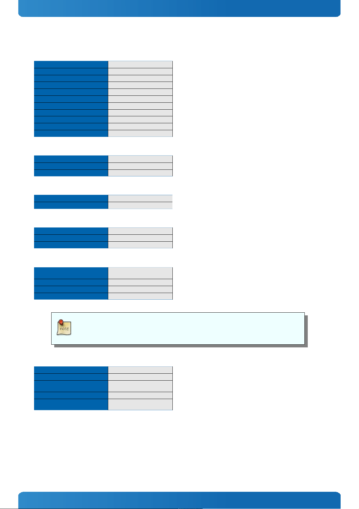
5.4.1 kboardinfo
Displays a summary of board and configuration information
Syntax
kboardinfo
Description
This command collects information from various board sources and provides a summary listing of this information.
Usage
==> kboardinfo
Manufacturer: Kontron Europe GmbH
Product name: SMARC-sAMX6i
Material number: 1052-9986
Serial number: UHD050004
Manufacturer Date: ^C09/20/2013
Revision: 020
CPU: Freescale i.MX6Q rev1.1 at 792 MHz
==>
5.4.2 md5sum
Creates or checks the md5 message digest over a memory area
Syntax
md5sum <data-address> <length> [<cksum-address>]
-md5sum
command
-<data-address>
parameter: hexadecimal
start address of memory area
-<length>
parameter: hexadecimal
length of memory area
-<chksum-address>
parameter: hexadecimal
If present: compares the calculated md5 message digest with the md5 message
digest available at this address.
If absent: calculates the md5 message digest over the specified memor y range and
prints it to the console.
Description
his command is used to create or check the md5 message digest over a memory area.
If the optional 3rd parameter <checksum-address> is omitted, the md5 message digest is calculated over the specified
33
Page 34

SMARC-sAMX6i / Bootloader Operation
memory range and printed to the console.
If the optional 3rd parameter <cksum-address> is specified, the md5 message digest is calculated over the specified
memory range and compared with the md5 message digest at <cksum-address>. If the digest is identical, the command
returns 0; if the digests do not match, a value other than zero is returned. When a comparison is made, nothing is printed
to the console since this usage of the command is meant to be used within scripts.
The md5 message digest at <cksum-address> may be specified in ASCII or binary format.
Usage
Calculate an md5 message digest: Check the md5 message digest of a file previously loaded to 100000 with a size of 80000
and its md5 message digest loaded to 10000 in a script
=> setenv check_crc “if md5sum 100000 80000 10000; then echo ‘md5 message
digest OK’; else echo ‘md5 message digest BAD’; fi”
=>run check_crc
md5 message digest OK
=>
34
Page 35

SMARC-sAMX6i / Bootloader Operation
5.5 U-Boot Access and Startup
Communication with U-Boot is achieved via a serial console configured for 115200 baud, 8N1, no hardware handshake.
Initially, U-Boot executes the commands defined in the environment variable “preboot”. Then, if not otherwise
interrupted, U-Boot pauses for the time defined in the environment variable “bootdelay” and then executes the
statements stored in the environment variable “bootcmd”. To gain access to the U-Boot command prompt, type in any
single character during the boot delay time.
If required, the boot delay function can be configured in such a way that even when the boot delay is set to “0” to have
characters, which are sent over the serial interface prior to the boot wait time, be recognized to allow operator
intervention in the boot process.
5.6 Environment
The Environment is stored in the same flash as U-Boot, usually in the last sector. This provides the possibility to update UBoot without changing the Environment. The environment can be modified by the user with the typical commands of the
‘env’ command group: ‘setenv’, ‘editenv’, ‘printenv’ and ‘saveenv’.
Furthermore, if a larger number of boards require updating the environment can be updated by a script, loaded from the
SD card, USB or SATA device, or a network.
A typical user modification would be to set the variable ‘bootcmd’ so that the user’s OS will boot automatically.
35
Page 36

SMARC-sAMX6i / Bootloader Operation
5.7 Working with U-Boot
5.7.1 General Operation
Most operations are carried out using the main memory as an intermediate step. It is not possible, for example, to boot a
kernel image directly from a tftp server. Instead, the kernel image is first loaded to memory and then booted from there
with another command.
The same is true when writing new contents to the SPI boot flashes.
This concept is very flexible since it separates the commands which handle the loading of data from the commands that
carry out actions like booting or programming flash devices.
5.7.2 Using the Network
U-Boot provides support for the onboard Ethernet interfaces for transferring files from a file server.
To be able to transfer files from a tftp server to a module, the module’s IP address (environment variable ‘ipaddr’) and
the IP address of the server must be set (environment variable ‘serverip’). Alternatively, it is possible to use the ‘dhcp’ or
‘bootp’ commands.
They can be set using the ‘setenv’ command. Please note, that these settings are lost after a reset. To retain the
environment permanently, use the command ‘saveenv’, which saves the complete environment to flash.
To transfer a file from a tftp server to memory, the ‘tftpboot’ command is used, for example:
> tftpboot 10800000 filename
5.7.3 Using SD Cards and onboard eMMC device
SD Cards are supported (read only) with the ‘ext2’ or ‘fat’ file system.
In both cases, the card must be rescanned first.
> mmc rescan 0
After that, the contents can be verified with:
> ext2ls mmc 0
in case of the ext2 file system, or
> fatls mmc 0
in case of the fat file system.
To load a file into memory the commands ‘ext2load’ or ‘fatload’ can be used, for example:
> ext2load mmc 0 10800000 kernel.bin
which loads the file ‘kernel.bin’ from the SD card to memory address 0x10800000.
5.8 Bootloader Update
Updating the bootloader of SMARC-sAMX6i can be done by using the already implemented update script.
5.8.1 Downloading the bootloader
Please download the regarding bootloader from Kontron's Customer Section.
5.8.2 Updating via TFTP Server
If you have a development setup with TFT Server please unpack the downloaded archive to your server's folder. There
should be a folder named “update_smx6”.
36
Page 37

SMARC-sAMX6i / Bootloader Operation
Restoring Environment
If your U-Boot envirenment is misconfigured you can restore it with following commands:
> tftp 10800000 amx6-(correct name of the environment).txt
> env import –d –t 10800000 $filesize
> saveenv
> reset
Running Update Script
To start the update script please enter following command:
> run netupdate
With the option ”-d” of the env import command you will lose all your previous made
environmental settings.
5.8.3 Updating via USB Stick
Unpack the downloaded archive to a USB stick's first partition. There should be a folder named “update_smx6”.
Please enter following command:
> run update
5.9 Bootlogo
A Kontron Bootlogo can be shown on an LVDS panel only. To control the bootlogo behaviour following commands can be
used:
> setenv panel LCD_WVGA@LVDS
Outputs the bootlogo on LVDS in panel resolution 800×480
> setenv panel LCD_WXGA@LVDS
Outputs the bootlogo on LVDS in panel resolution 1280×768
> setenv panel off
Disable LVDS output
> setenv panel
Outputs the bootlogo on LVDS in panel resolution 800×480 shipping default (variable unset)
To save the setting for the next boot, please save your environment with
> saveenv
The bootlogo can be not exchanged to another bitmap.
.
.
.
37
Page 38

SMARC-sAMX6i / Bootloader Operation
.
.
.
.
.
..
.
.
.
.
.
.
.
.
.
.
.
.
.
.
.
.
.
.
.
.
.
.
.
.
.
.
.
.
.
.
.
.
.
.
.
.
.
Corporate Offices
Europe, Middle East & Africa
Oskar-von-Miller-Str. 1
85386 Eching/Munich
Germany
Tel.: +49 (0)8165/ 77 777
Fax: +49 (0)8165/ 77 219
info@kontron.com
North America
14118 Stowe Drive
Poway, CA 92064-7147
USA
Tel.: +1 888 294 4558
Fax: +1 858 677 0898
info@us.kontron.com
Asia Pacific
17 Building,Block #1,ABP.
188 Southern West 4th Ring
Beijing 100070, P.R.China
Tel.: + 86 10 63751188
Fax: + 86 10 83682438
info@kontron.cn
38
 Loading...