

Page 1
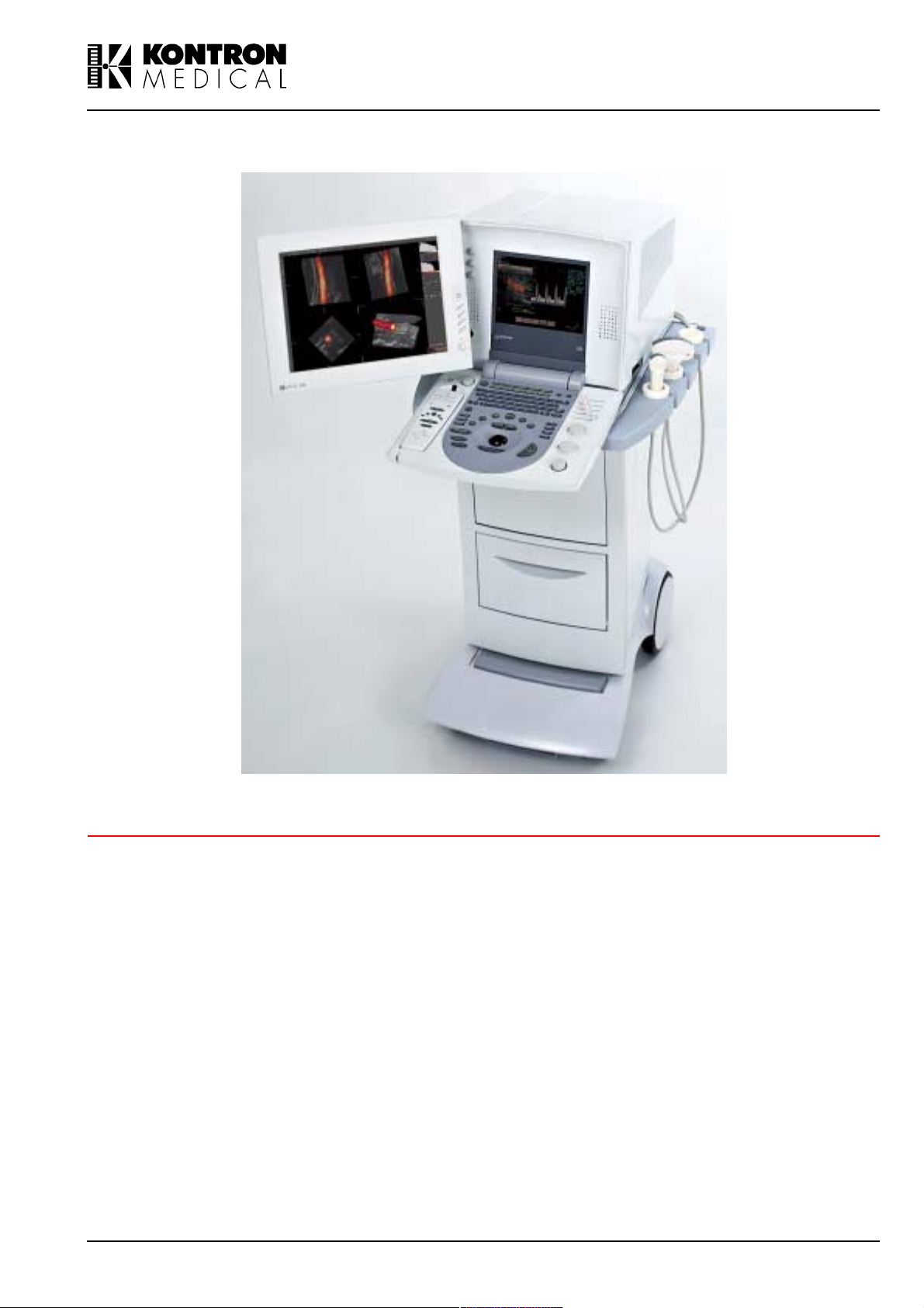
IMAGING
SIGMA 110/SIGMA 330
Operator Manual
(Software Version V 5.XX)
© Copyright by KONTRON MEDICAL, 2001
Ref.: DOC31001EN Issue date: 10.12.01 Issue: 4
Page 2

Page 3

GENERAL INFORMATION
15.10.01 GENERAL INFORMATION i
Page 4

ii SIGMA 110/SIGMA 330 15.10.01
Page 5

I. Copyright
© 2001 by KONTRON MEDICAL SAS
ALL RIGHTS RESERVED
PRINTED IN FRANCE
The information contained in this publication may not be used for any purpose other than that for
which it was originally supplied. The publication may not be reproduced in part or in whole without written consent of KONTRON MEDICAL SAS. In order to maintain and improve standards of
manufacturing, methods of functioning and reliability, KONTRON MEDICAL SAS equipments are
periodically reviewed. For this reason, the content of this publication is subject to change without
any notice.
This product contains KONTRON MEDICAL proprietary software in machine-readable form.
KONTRON MEDICAL SAS retains all its rights, title and interest in the software. Purchase of this
product includes a license to use the software contained in it. The purchaser shall not copy, trace,
disassemble or modify the software, nor cause or allow this software to be copied, traced, disassembled or modified. Transfer of this product by the purchaser will constitute a transfer of this
license, which will not be transferable otherwise.
The equipment described is manufactured by:
KONTRON MEDICAL S.A.S.
Boite Postale 97
78373 PLAISIR CEDEX
FRANCE
Internet: www.kontronmedical.com
Apple, Macintosh, iMac, MacOS, FireWire are registered trademarks of Apple Computer, Inc.
Intel®, Pentium® and Pentium III® are registered trademarks of Intel Corporation.
Linux is a registered trademark of Linus Torvalds.
Matrox® is a registered trademark of Matrox Electronic Systems Ltd.
Microsoft® and Windows® are registered trademarks of Microsoft Corporation.
USB is a registered trademark of USB Implementers Forum, Inc.
SonoWin®, SonoWinlite® and SonoWinbasic® are registered trademarks of Meso.
15.10.01 GENERAL INFORMATION iii
Page 6

II. Quality, Reliability and Safety
This equipment has been designed with high standards of quality, reliability and safety. KONTRON MEDICAL SAS can however only accept the corresponding manufacturers responsibility
providing the following conditions are met: Electrical installations of the room or building in which
the equipment is to be used must comply with the relevant national regulations. The equipment is
used in accordance with the instructions for use provided by KONTRON MEDICAL SAS (Operator manual). All modifications and repairs to the equipment are carried out by authorized KONTRON MEDICAL personnel, or their agents. The equipment must comply with regulations
specified in the "Safety Informations" section.
Your local KONTRON MEDICAL company or agent is: (To be filled by local KONTRON MEDICAL
company or agent.)
iv SIGMA 110/SIGMA 330 15.10.01
Page 7

TABLE OF CONTENTS
10.12.01 v
Page 8

vi SIGMA 110/SIGMA 330 10.12.01
Page 9

I. Copyright ..........................................................................................iii
II. Quality, Reliability and Safety.......................................................... iv
III. Intended Clinical Use and Safety Information ................................ xv
IV. Compliance with Standards...........................................................xxx
1. INSTRUMENT DESCRIPTION .....................................................1-1
1.1 Introduction.............................................................................................................. 1-3
1.2 SIGMA 110/330 Equipments................................................................................... 1-5
1.3 Physical Description ................................................................................................ 1-7
1.3.1 Electronic Cabinet...................................................................................... 1-11
1.3.2 Control Panel ............................................................................................. 1-11
1.3.3 TV Monitor ................................................................................................. 1-15
1.3.4 Front Panel ................................................................................................ 1-17
1.3.5 Rear Panel................................................................................................. 1-22
1.4 System Controls .................................................................................................... 1-28
1.4.1 Alphanumeric Keys.................................................................................... 1-28
1.4.2 Live Investigation Keys .............................................................................. 1-29
1.4.3 Keys for Frozen Image Study..................................................................... 1-30
1.4.4 Trackball..................................................................................................... 1-31
1.5 Screen Layout ....................................................................................................... 1-33
1.5.1 Ultrasound Screen Layout ......................................................................... 1-33
1.5.2 Menu.......................................................................................................... 1-36
1.5.3 Technical Data Area................................................................................... 1-38
1.6 Display Modes....................................................................................................... 1-42
1.6.1 2D Modes .................................................................................................. 1-42
1.6.2 TM Modes.................................................................................................. 1-42
1.6.3 CW and PW Modes ................................................................................... 1-43
1.6.4 CFM Formats............................................................................................. 1-43
1.7 SIGMA 110 Technical Specifications..................................................................... 1-44
1.7.1 General ...................................................................................................... 1-44
1.7.2 2D (B-Mode) .............................................................................................. 1-46
1.7.3 TM (M-Mode) ............................................................................................. 1-46
1.7.4 Spectral Doppler Mode.............................................................................. 1-47
1.7.5 Digital Archiving: KIPRISM ........................................................................ 1-48
1.7.6 ECG Module (option)................................................................................. 1-48
1.7.7 EasyPrintTM .............................................................................................. 1-49
1.7.8 USB-LinkTM .............................................................................................. 1-49
1.7.9 Peripherals (Optional)................................................................................ 1-49
1.7.10 Inputs/Outputs ........................................................................................... 1-49
1.7.11 Measurement............................................................................................. 1-49
1.7.12 Acoustic Power .......................................................................................... 1-51
1.7.13 Environment............................................................................................... 1-51
1.7.14 Regulation and Safety ............................................................................... 1-51
10.12.01 TABLE OF CONTENTS vii
Page 10

1.7.15 Dimensions ................................................................................................1-52
1.8 SIGMA 330 Technical Specifications .....................................................................1-53
1.8.1 General ......................................................................................................1-53
1.8.2 2D (B-Mode)...............................................................................................1-55
1.8.3 TM (M-Mode) .............................................................................................1-56
1.8.4 Spectral Doppler Mode ..............................................................................1-56
1.8.5 Colour Doppler Modes ...............................................................................1-58
1.8.6 3D Imaging.................................................................................................1-58
1.8.7 Digital Archiving: KIPRISM.........................................................................1-59
1.8.8 ECG Module (option) .................................................................................1-59
1.8.9 EasyPrintTM...............................................................................................1-59
1.8.10 USB-LinkTM...............................................................................................1-59
1.8.11 Peripherals (Optional) ................................................................................1-60
1.8.12 Inputs/Outputs............................................................................................1-60
1.8.13 Measurement .............................................................................................1-60
1.8.14 Acoustic Power...........................................................................................1-61
1.8.15 Environment...............................................................................................1-62
1.8.16 Regulation and Safety................................................................................1-62
1.8.17 Dimensions ................................................................................................1-62
2. INSTALLATION ............................................................................. 2-1
2.1 Installation Requirements ........................................................................................2-3
2.2 Unpacking ................................................................................................................2-3
2.2.1 Warning........................................................................................................2-3
2.2.2 Unpacking the Instrument ............................................................................2-3
2.3 Checking the Instruments Identification ...................................................................2-3
2.4 Checking the Delivery ..............................................................................................2-4
2.5 Transport...............................................................................................................2-6
2.6 Installation of SIGMA 330 Expert and SIGMA 330 Excellence................................2-7
2.6.1 Installation of the integrated cart ..................................................................2-7
2.6.2 Installation of the flat panel monitor .............................................................2-8
2.6.3 Installation of the integrated compact PC (SIGMA 330 Excellence only).....2-8
2.7 Power Source Connection .....................................................................................2-10
2.7.1 Input Power Source....................................................................................2-10
2.7.2 Output Power Source .................................................................................2-11
2.8 Connecting a Probe ...............................................................................................2-12
2.8.1 SIGMA 330 Expert and SIGMA 330 Excellence Probe Assignment..........2-12
2.8.2 SIGMA 110 Light/Master and SIGMA 330 Master Probe Assignment....... 2-13
2.8.3 Probe Connection ......................................................................................2-13
2.9 Connection of Peripherals......................................................................................2-15
2.9.1 Electrical safety with peripherals................................................................2-15
2.9.2 Recommended Peripherals........................................................................2-17
2.9.3 Archiving on Personal Computer................................................................2-17
2.9.4 Connection of B&W Video Printer..............................................................2-18
2.9.5 Connection of Colour Video Printer............................................................2-19
viii SIGMA 110/SIGMA 330 10.12.01
Page 11

2.9.6 Video Recorder (VCR)............................................................................... 2-20
2.9.7 ECG Module .............................................................................................. 2-22
2.9.8 Colour Monitors ......................................................................................... 2-23
2.9.9 Black & White Monitor ............................................................................... 2-25
2.9.10 Printer ........................................................................................................ 2-26
2.9.11 Connection with medical grade isolators ................................................... 2-32
2.9.12 Connection with S-Video Distributor.......................................................... 2-33
3. OPERATING INSTRUCTIONS......................................................3-1
3.1 Operating Precautions............................................................................................. 3-3
3.2 Switching the Instrument ON................................................................................... 3-4
3.2.1 Switching ON SIGMA 110 and SIGMA 330 Master..................................... 3-4
3.2.2 Switching ON SIGMA 330 Expert................................................................ 3-4
3.2.3 Switching SIGMA 330 Excellence ON ......................................................... 3-4
3.2.4 Initialization of SIGMA ................................................................................. 3-5
3.3 Switching the Instrument OFF................................................................................. 3-6
3.3.1 Switching OFF SIGMA 110 and SIGMA 330............................................... 3-6
3.3.2 Switching OFF SIGMA 330 Excellence ....................................................... 3-6
3.4 Menus...................................................................................................................... 3-7
3.4.1 Notes ........................................................................................................... 3-7
3.4.2 Menu Key Conventions................................................................................ 3-7
3.4.3 Menu Types ................................................................................................. 3-7
3.4.4 Menu Display ............................................................................................... 3-7
3.4.5 Menu Items .................................................................................................. 3-8
3.5 Probes ................................................................................................................... 3-11
3.5.1 Probe Selection ......................................................................................... 3-11
3.5.2 Menu Display ............................................................................................. 3-11
3.6 Setup .................................................................................................................... 3-13
3.6.1 Setup Menu ............................................................................................... 3-13
3.6.2 Loading a Setup......................................................................................... 3-13
3.6.3 Saving a Setup .......................................................................................... 3-13
3.6.4 Deleting a Setup ........................................................................................ 3-14
3.6.5 Preferences ............................................................................................... 3-14
3.6.6 PCMCIA CARD.......................................................................................... 3-23
3.6.7 System Info................................................................................................ 3-23
3.7 Major Modes.......................................................................................................... 3-25
3.7.1 2D Mode .................................................................................................... 3-25
3.7.2 TM (Time Motion) ...................................................................................... 3-31
3.7.3 PW Doppler ............................................................................................... 3-34
3.7.4 CW Doppler ............................................................................................... 3-39
3.7.5 CFM Mode ................................................................................................. 3-42
3.7.6 3D imaging................................................................................................. 3-46
3.8 Print .......................................................................................................................3-47
3.9 Cine Mode............................................................................................................. 3-48
3.9.1 Storing Pictures ......................................................................................... 3-48
10.12.01 TABLE OF CONTENTS ix
Page 12

3.9.2 Displaying Pictures.....................................................................................3-49
3.9.3 Cine Auto-Replay .......................................................................................3-49
3.10 Magnifier in 2D and CFM Mode.............................................................................3-50
3.11 Digital Archiving: KIPRISM ....................................................................................3-51
3.11.1 Image Storage and Freeze Menu...............................................................3-51
3.11.2 Archive: Display of Stored Images .............................................................3-52
3.11.3 Using the Memory Card on PC ..................................................................3-54
3.11.4 Patient Report and Patient ID with KIPRISM .............................................3-55
3.12 Annotations............................................................................................................3-59
3.12.1 Entering Annotation Mode..........................................................................3-59
3.12.2 Exiting the Annotation Mode ......................................................................3-59
3.12.3 Manual Text Annotation..............................................................................3-60
3.12.4 Labels.........................................................................................................3-60
3.12.5 Arrows ........................................................................................................3-64
3.13 Body Markers.........................................................................................................3-65
3.13.1 Displaying Body markers............................................................................3-65
3.13.2 Moving Body Markers.................................................................................3-66
3.13.3 Deleting Body markers...............................................................................3-66
3.13.4 Medical.......................................................................................................3-66
3.13.5 Deleting All Annotations.............................................................................3-66
3.14 Measurements .......................................................................................................3-67
3.14.1 Generalities ................................................................................................3-67
3.14.2 Starting a Measurement.............................................................................3-68
3.14.3 2D Measurement........................................................................................3-68
3.14.4 CFM Measurement ....................................................................................3-75
3.14.5 TM Measurement.......................................................................................3-77
3.14.6 Doppler Measurement................................................................................3-82
3.15 Biometry and Report..............................................................................................3-90
3.15.1 Biometry Pictograms..................................................................................3-90
3.15.2 Patient Information .....................................................................................3-90
3.15.3 Biometry Patient Study...............................................................................3-90
3.15.4 Report ........................................................................................................3-91
3.15.5 Starting a Study..........................................................................................3-91
3.15.6 Radiology Study.........................................................................................3-92
3.15.7 Obstetrics/Gynaecology Study...................................................................3-93
3.15.8 Vascular Study ...........................................................................................3-94
3.15.9 Cardiology Study........................................................................................3-94
3.16 ECG (Option) .........................................................................................................3-95
3.17 EasyPrint Options...............................................................................................3-96
3.17.1 Printing of images ......................................................................................3-96
3.17.2 Printing of Report .......................................................................................3-98
3.18 USB-Link Option.................................................................................................3-99
3.18.1 Overview ....................................................................................................3-99
3.18.2 Compatibility...............................................................................................3-99
3.18.3 Usage example with Windows® 2000........................................................3-99
3.18.4 Read data from a computer .....................................................................3-101
x SIGMA 110/SIGMA 330 10.12.01
Page 13

3.18.5 Copy data to the computer ...................................................................... 3-101
3.18.6 Interface with PACS ................................................................................. 3-102
3.18.7 Limitations................................................................................................ 3-102
3.19 SonoWin® Lite and SonoWin® Basic PACS ....................................................... 3-103
3.19.1 Overview.................................................................................................. 3-103
3.19.2 Start a Study............................................................................................ 3-104
3.19.3 Save images, reports and patient information ......................................... 3-105
3.19.4 Transfer data to SonoWin®...................................................................... 3-106
3.19.5 Data Assignment ..................................................................................... 3-109
3.20 Integrated PC (SIGMA 330 Excellence) .............................................................. 3-110
3.20.1 Overview.................................................................................................. 3-110
3.20.2 SAFETY PRECAUTIONS........................................................................ 3-110
3.20.3 Entering PC remote control mode ........................................................... 3-111
3.20.4 PC remote control features description ................................................... 3-111
3.20.5 Leaving PC remote control mode ............................................................ 3-111
3.20.6 Keyboard in PC mode.............................................................................. 3-111
3.20.7 Errors and warnings................................................................................. 3-114
3.20.8 PC power on............................................................................................ 3-114
3.20.9 PC power off............................................................................................ 3-114
3.20.10 3D VascularView and 3D FetalView ................................................. 3-115
3.20.11 PACS option............................................................................................. 3-115
3.20.12 Connection to a Network ......................................................................... 3-115
3.20.13 Installation of peripherals......................................................................... 3-115
4. MAINTENANCE ............................................................................4-1
4.1 Cleaning .................................................................................................................. 4-3
4.1.1 Probes ......................................................................................................... 4-3
4.1.2 TV Monitor ................................................................................................... 4-3
4.1.3 EYE-Q 300M Monitor................................................................................... 4-3
4.1.4 Keyboard...................................................................................................... 4-3
4.1.5 Instrument.................................................................................................... 4-4
4.2 Disinfection .............................................................................................................. 4-5
4.3 Repairs and Maintenance........................................................................................ 4-8
4.3.1 User Maintenance........................................................................................ 4-8
4.3.2 Manufacturer Maintenance .......................................................................... 4-9
4.4 Product Recycling and Disposal............................................................................ 4-10
5. TROUBLESHOOTING ..................................................................5-1
5.1 Handle Error and Warning Messages ..................................................................... 5-3
5.2 Introduction and Rules............................................................................................. 5-4
5.2.1 Rules............................................................................................................ 5-4
5.2.2 Definition...................................................................................................... 5-4
5.2.3 Remarks ...................................................................................................... 5-4
5.3 Status Messages..................................................................................................... 5-5
10.12.01 TABLE OF CONTENTS xi
Page 14

5.3.1 ECG .............................................................................................................5-5
5.3.2 Measurement and Biometry .........................................................................5-7
5.3.3 Transmit Voltage Indicator ............................................................................5-8
5.4 Warnings..................................................................................................................5-9
5.4.1 Start-up checks ............................................................................................5-9
5.4.2 System Configuration Check......................................................................5-10
5.4.3 Flash card and SRAM................................................................................5-11
5.4.4 Miscellaneous checks ................................................................................5-13
5.5 General Failures and Errors...................................................................................5-18
5.5.1 Error 0: Internal unexpected interrupt ........................................................5-18
5.5.2 Error 1: Can not restore backed up configuration ......................................5-18
5.5.3 Error 2: Tracking problem - Fatal error .......................................................5-19
5.5.4 Error 3: Memory allocation error - Fatal error.............................................5-19
5.5.5 Error 4: Divide by 0 - Fatal error.................................................................5-19
5.5.6 Error 5: Communication error.....................................................................5-19
5.5.7 Error 6: Flash card read error.....................................................................5-19
5.5.8 Error 7: Flash card write error ....................................................................5-19
5.5.9 Error 8: Invalid flash card type....................................................................5-20
5.5.10 Error 9: Ob/Gyn restore error.....................................................................5-20
5.5.11 Error 10: Flashcard not correctly formatted................................................5-20
5.5.12 Error 11: Internal Communication - Fatal error...........................................5-20
5.5.13 Error 12: Cannot program TMPAVG...........................................................5-20
5.5.14 Error 13: CFM Frame Filter LUT Error .......................................................5-21
5.5.15 Error 14: CFM Function LUT Error.............................................................5-21
5.5.16 Error 15: CFM LUT programming time out error ........................................5-21
5.5.17 Error 16: Flashcard removed while printing................................................5-21
5.5.18 Error 17: Internal communication - Fatal error ...........................................5-21
6. OPTIONS AND ACCESSORIES .................................................. 6-1
6.1 Options.....................................................................................................................6-3
6.2 List of Probes...........................................................................................................6-4
6.3 Accessories..............................................................................................................6-5
7. APPENDICES............................................................................... 7-1
Appendix A: Overview .................................................................. 7-3
A.1 Entering the Biometry ......................................................................................7-3
A.2 Exiting the Biometry .........................................................................................7-3
A.3 Make a Measurement from Report ..................................................................7-3
A.4 Importing Measurements in Report .................................................................7-4
Appendix B: Report Menu............................................................. 7-5
Appendix C: Patient Information ................................................... 7-7
C.1 First Page ........................................................................................................7-7
C.2 Second Page ...................................................................................................7-9
xii SIGMA 110/SIGMA 330 10.12.01
Page 15

Appendix D: Cardiology Study..................................................... 7-11
D.1 Left Ventricle Study ....................................................................................... 7-12
D.2 Mitral Valve Study ......................................................................................... 7-18
D.3 Aortic Valve Study ......................................................................................... 7-22
D.4 Right Ventricle Study .................................................................................... 7-26
Appendix E: Vascular Study........................................................7-31
E.1 Description .................................................................................................... 7-31
E.2 Stenosis Percentage ..................................................................................... 7-31
E.3 Equations ...................................................................................................... 7-33
Appendix F: Ob/Gyn Studies.......................................................7-37
F.1 2D Sheet ....................................................................................................... 7-37
F.2 TM/SP Sheet ................................................................................................. 7-41
F.3 Foetal Information Sheet ............................................................................... 7-43
F.4 Setup Sheet .................................................................................................. 7-44
F.5 User Table Sheet .......................................................................................... 7-47
F.6 Curve View .................................................................................................... 7-48
Appendix G: Reference Tables for Ob/Gyn .................................7-49
G.1 Biparietal Diameter (BPD) ............................................................................. 7-49
G.2 Chorion Diameter (ChD) from Rempen ........................................................ 7-57
G.3 Femur Length (FML) ..................................................................................... 7-58
G.4 Humerus Length (HuL) ................................................................................. 7-65
G.5 Transabdominal Diameter (TAD) from Merz ................................................. 7-67
G.6 Thoracic Diameter (THD) from Hansmann .................................................. 7-68
G.7 Anterior Posterior Diameter (APD) ................................................................ 7-69
G.8 Crown Rump Length (CRL) .......................................................................... 7-71
G.9 Gestational Sac (GES) .................................................................................. 7-76
G.10 Abdominal Circumference (AC) .................................................................... 7-78
G.11 Head Circumference (HC) ............................................................................ 7-81
G.12 Binocular Distance (BOD) from Jeanty ......................................................... 7-84
G.13 Occipital Frontal Diameter (OFD) from Merz ................................................ 7-84
Appendix H: Radiology Study......................................................7-85
H.1 Description .................................................................................................... 7-85
H.2 Equations ...................................................................................................... 7-86
Appendix I: Measurement Interface ...........................................7-89
I.1 Doing a Measurement from Report ............................................................... 7-89
I.2 Importing Measurements in Report ............................................................... 7-91
Appendix J: Print Preview...........................................................7-93
J.1 Edit the Printable Report ............................................................................... 7-93
10.12.01 TABLE OF CONTENTS xiii
Page 16

J.2 Print the Report on an External Printer ..........................................................7-94
J.3 Save the Report on a Flashcard ....................................................................7-94
Appendix K: KIPRISM / SonoWin® Basic Conversion Tables.... 7-95
K.1 Overview ........................................................................................................7-95
K.2 Cardiology Measurements .............................................................................7-95
K.3 Vascular measurements ..............................................................................7-102
K.4 Obstetric and Gynaecology .........................................................................7-104
K.5 Radiology Study ..........................................................................................7-108
K.6 Multiple associations ...................................................................................7-109
Appendix L: Body Markers ....................................................... 7-111
L.1 Vascular .......................................................................................................7-111
L.2 Radiology .....................................................................................................7-111
L.3 Obstetrics/ Gynaecology .............................................................................7-112
L.4 Cardiology ...................................................................................................7-112
Appendix M:Acoustic Output Tables ........................................ 7-113
M.1 Track3 Summary Tables .............................................................................7-113
M.2 Definition of Terms ......................................................................................7-114
M.3 Acoustic Output Tables ...............................................................................7-116
xiv SIGMA 110/SIGMA 330 10.12.01
Page 17

III. Intended Clinical Use and Safety Information
This system complies with the Medical Device Directive (MDD) 93/42/EEC, according to which
KONTRON MEDICAL has classified this device as a Class 1 Type B device.
Note for U.S. Customers
U.S Federal Law restricts this device to sale, distribution and use by or on the order of a
physician.
III.1 .Intended Clinical Use
The SIGMA 110 / 330 is intended for visualization by ultrasound of internal organs, for medical
diagnostic purposes only. It must be operated by qualified and trained Physician or "Sonographer".
The particular organs visualized, and the methods of visualization, depend on the particular
transducer used, and the imaging mode employed.
Modes are used in two senses in this manual: Imaging Modes refer to the method of depicting
the organs visualized, and are explained below. It is also used to indicate various operational
modes, such as freeze, zoom, cine, etc. In general, it is obvious when a non-imaging mode
is referred to. In the manual they are explained when they are first used.
The principal imaging modes of the SIGMA 110/330 and their abbreviations, which are used
throughout this manual, are as follows:
2D: Two-dimensional representation of a slice in the body, often called B-mode.
TM: Often called just M-Mode, the ultrasound beam is stationary (giving an A-scan), but the
time axis moves, with the result that moving organs can be easily visualized.
PW: Pulse Wave Doppler, which permits determining the velocity of blood or another organ in the
interior of the body.
CW: Continuous Wave Doppler, which determines the velocity of flow or movement of all ele-
ments within the range of the probe.
CFM: Colour-flow mapping, which superimposes a map of the velocity of moving organs or blood
on top of a 2D scan (B-scan) of the organs.
The SIGMA 110/330 does not permit composite modes (two modes produced at the same
time). However, two modes can be made sequentially and then displayed next to each other on
the same screen. If two modes are displayed together, this is called a double-pad mode. If only
one is displayed, it is called a single-pad mode.
15.10.01 GENERAL INFORMATION xv
Page 18

These are all real-time displays. However, an image can be frozen at a particular point in time
to produce a static display so that it may be studied in more detail later.
Imaging modes are explained in more detail in Chapter 3.7, Major Modes, on page 3-25
The following table lists the SIGMA 110 / 330 probes and their intended clinical use:
PROBE TYPE
3.5 MHz CV 3.5 Abdominal, Ob/Gyn 2D/TM/PW/CFM
3.5 MHz MC 3.5
6.5 MHz MC 6.5
5.0 MHz LV 5
7.5 MHz LV 7.5
7.5 MHz LVS 7.5
6.5 MHz EV 6.5 Ob/Gyn, Urology 2D/TM/PW
6.5 MHz MR 6.5
6.5 MHz VMC 6.5 Ob/Gyn, Urology 2D/TM/PW/CFM
3.5 MHz GP 3.5
5.0 MHz GP 5.0
7.5 MHz GP 7.5
14 MHz PV 14
PEN 2 MHz 2
PEN 4 MHz 4 Vascular PW/CW
PEN 8 MHz 8 Vascular PW/CW
TCD 2 MHZ 2 Transcranial Doppler PW
Nominal Frequency
(MHz)
Convex Linear Probes
Cardiology, Transcranial
Linear Probes
Pediatrics, Perivascular
Pediatrics, Perivascular,
Pediatrics, Perivascular,
Endocavitarian Probes
Endorectal multiplane for
Annular Sector Probes
Cardiology, Abdominal,
Perivascular, Small Parts,
Breast, Muskuloskeletal
Pencil Probes
PROBE
APPLICATIONS
Abdominal,
Vascular/Angiology
Pediatrics, Cardiology,
Vascular/Angiology
Abdominal, Obstetrics,
Small Parts
Small Parts
Urology
Ob/Gyn
Abdominal, Ob/Gyn
Cardiology, Pediatrics
Vascular, Small parts,
Neonatology
Cardiovascular
MODES
2D/TM/PW/CFM
2D/TM/PW/CFM
2D/TM/PW/CFM
2D/TM/PW/CFM
2D/TM/PW/CFM
2D/TM/PW
2D/TM/PW/CW
2D/TM/PW/CW
2D/TM/PW/CW
2D/TM/PW
PW/CW
Tab l e i : Probe applications
Details on the various applications are below.
xvi SIGMA 110/SIGMA 330 15.10.01
Page 19

Abdominal / Gynaecology / Urology Application
The probe applies ultrasound energy through the patient abdomen to obtain an image of the
abdominal organs to detect abnormalities (imaging) and assess the blood velocity, flow and patency of abdominal vessels through the Doppler modalities.
Perivascu lar Ap plication
The probe applies ultrasound energy through the neck or extremities of a patient to obtain an
image of the carotid artery, or other peripheral vessels, that can be used to detect abnormalities
or obstructions in the vessel. In Doppler modes, the probe applies ultrasound energy through the
neck or extremities of a patient to assess the blood velocity, flow or lack of flow and patency of
peripheral vessels.
Small Parts Application
The probe applies ultrasound energy through the skin to obtain an image or a Doppler flow visualization of small organs such as the thyroid (neck), testicles (scrotal sac) and breast.
Cardiology Application
The probe applies ultrasound energy through the chest wall to obtain an image of the heart for
purpose of assessing cardiac abnormalities. In Doppler modes, the probe applies energy through
the chest wall to determine the velocity and direction of blood in the heart and in the vessels.
Obstetrics / Fetal Application
The probe applies ultrasound energy through a pregnant womans abdomen to obtain an image
of the fetus to detect structural abnormalities or to visualize and measure anatomical and physiological parameters of the fetus for the purpose of assessing fetal growth. In Doppler modes, the
probe applies energy through the patient abdomen to detect placental or fetal flow abnormalities.
Note
The user should always follow the ALAR A (As Low As Reasonably Achievable) principle,
but especially in Obstetrics / Fetal applications. Use the lowest amount of acoustic output
power for the shortest duration of time to obtain the necessary clinical diagnostic information.
Neonatology Application
The probe applies ultrasound energy through the neonatal head fontanelles to visualize brain
structures (imaging) or flow (Doppler) to detect structural or functional abnormalities.
WARNING: This system is not to be used for transorbital or any other ophtalmic applications.
Transcranial Doppler
The probe applies ultrasound energy through the adult patient skull to, visualize flow (Pulsed
Wave Doppler) to detect functional abnormalities.
15.10.01 GENERAL INFORMATION xvii
Page 20

WARNING: This system is not to be used for transorbital or any other ophtalmic applications.
The main features of the probes are shown in the table below:
Frequency
PROBE
TYPE
Range
(FL to F H
Scanning
in MHz)
Angle
(degree)
3.5 MHz CV 2 - 5 45 - 60 - 70 1.2 0.7 - 86.4 x 12
3.5 MHz MC 2 - 5 30 - 90 - 70 1.5 0.7 - 38.2 x 11
6.5 MHz MC 4 - 9 30 - 90 - 45 0.6 0.4 - 33.4 x 6.5
5.0 MHz LV 3 - 7 - 63 50 1.0 0.5 - 86.4 x 11
7.5 MHz LV 4 - 10 - 50 20 0.6 0.3 - 59.4 x 4.5
7.5 MHz LVS 4 - 12 - 38 25 0.5 0.3 - 38.4 x 6.5
6.5 MHz EV 4 - 9 90 - 140 - 25 0.7 0.4 9 -
6.5 MHz MR 4 - 9 90 - 110 - 25 0.7 0.4 8 -
6.5 MHz VMC 4 - 9 45 - 111 - 45 0.6 0.4 - 33.4 x 6.5
3.5 MHz GP 2 - 5 45 - 90 - 70 1.6 0.8 16 -
5.0 MHz GP 3 - 7 45 - 90 - 40 0.8 0.5 11.4 -
7.5 MHz GP 5 - 10 40 - 90 - 20 0.4 0.3 7 -
14 MHz PV 8 - 16 40 - 15 0.3 0.2 5.5 -
TCD 2 MHZ 2 - - 45 3 - 15 -
PEN 2 MHz 2 - - 45 3 - 13 -
PEN 4 MHz 4 - - 30 2 - 9 -
PEN 8 MHz 8 - - 20 2 - 6 -
Width
(mm)
Convex
Linear
Endocavitarian
Annu lar Sector
Pencil
Focal
Point
(mm)
Resolution Ceramics
lateral
(mm)
axial
(mm)d (mm)
L x W
(mm)
Tab l e i i : Probe Features
III.2.Safety Information
In this manual a WAR NI NG pertains to possible injury to a patient and/or the sonographer. A
CAUTION describes the precaution which are necessary to protect the equipment.
Be sure that you understand and observe each of cautions and warnings.
xviii SIGMA 110/SIGMA 330 15.10.01
Page 21

III.2.1 . Electrical Safety
As defined in EN60601-1 (IEC Standard 601-1, safety of Medical Electrical Equipment), this
equipment is classified as Class I, type B (probes), while the ECG module has a Class CF
degree of protection.
WAR NINGS
The system must be properly grounded to prevent shock hazards. Protection is provided by
grounding the chassis with a three wire cable and plug; the system must also be powered
through a properly grounded receptacle.
Electrical shock hazard. Do not remove any panel. Refer servicing and internal adjustments
to qualified KONTRON personnel only.
For continued protection against risk of fire, replace fuses only with fuses of the same type
and rating (see Chapter 2.7, Power Source Connection, on page 2-10).
The equipment is not suitable for use in the presence of a flammable anaesthetic mixture with
air, oxygen or nitrous oxide. Do not use the system in the presence of flammable anaesthetics. Explosion is a hazard under such conditions.
The system not watertight and provides a class IP(X)0 degree of protection to liquids; do not
expose the system to rain or moisture. Avoid placing liquid containers on the system.
Remove probes and electrocardiography leads from patient contact before applying a high
voltage defibrillation pulse.
Like any other ultrasound equipment, the SIGMA 110/330 uses high frequency signals which
could interfere with pacemakers. You should be aware of this small potential hazard and
immediately turn off the unit if interference in the pacemaker operation is noted or suspected.
If you drop or strike a probe, do not use it until a measurement of the electrical leakage cur-
rent has demonstrated that a electrical safety has not been compromised. It is also necessary
to insure that the probe has not been cracked or damaged so that it produces erroneous
scans.
Do not immerse the entire probe in liquids to clean it. The probe is not watertight and immer-
sion may compromise the electrical safety features of the probe. Carefully follow the cleaning
instructions in this manual.
Take all appropriate precautions to avoid impact damage to the sensitive face of the probe.
The use of products not approved by KONTRON MEDICAL such as oil, Methylene blue, ether
or some disinfectants could cause permanent damage to the sensitive part of the transducer.
Only the KONTRON MEDICAL supplied gel (KONTRON supply part number 100 250, ultra-
sonic gel) is recommended by KONTRON MEDICAL for coupling the transducer to the skin.
The use of an agent other than the approved gel may adversely affect the quality of the
images and produce substandard results.
The cart available with the SIGMA 330 Expert and SIGMA 330 Excellence provides insulated
plugs and connectors to manage optional hard copy devices (VCR, printers). Follow the
instructions in this manual to install such a device. Wrong connections may compromise the
electrical safety of the system.
Never connect additional peripherals directly to wall outlets; use a medical grade isolating
transformer which must comply with IEC 601-1 specifications. Wrong connections may com-
promise the electrical safety of the system.
KONTRON MEDICAL provides a medical grade isolating transformer and isolating accesso-
ries on request, see Chapter 6.3, Accessories, on page 6-5 for ordering.
15.10.01 GENERAL INFORMATION xix
Page 22
Never connect Network (RJ-45) directly to the system; use a medical grade network isolator
which must comply with IEC 601-1 specifications. Wrong connections may compromise the
electrical safety of the system.
KONTRON MEDICAL provides a medical grade isolator on request, see Chapter 6.3, Accessories, on page 6-5 for ordering.
CAUTIONS
In order to prevent an overheating, ensure that the ventilation openings are not covered and
keep the SIGMA 110/330 rear panel away from a vertical wall.
To prevent further damage to your system and the accessories, power off the unit if it does not
start up correctly.
Never expose the probes to gas, heat or unauthorized liquid sterilization procedures (see
probe cleaning instructions). These methods can permanently damage the probe.
Do not connect or disconnect an active probe during live scanning; the system must be in
freeze mode or turned off to connect or disconnect a probe.
Carefully follow the Operators Manual instructions to clean or disinfect a probe.
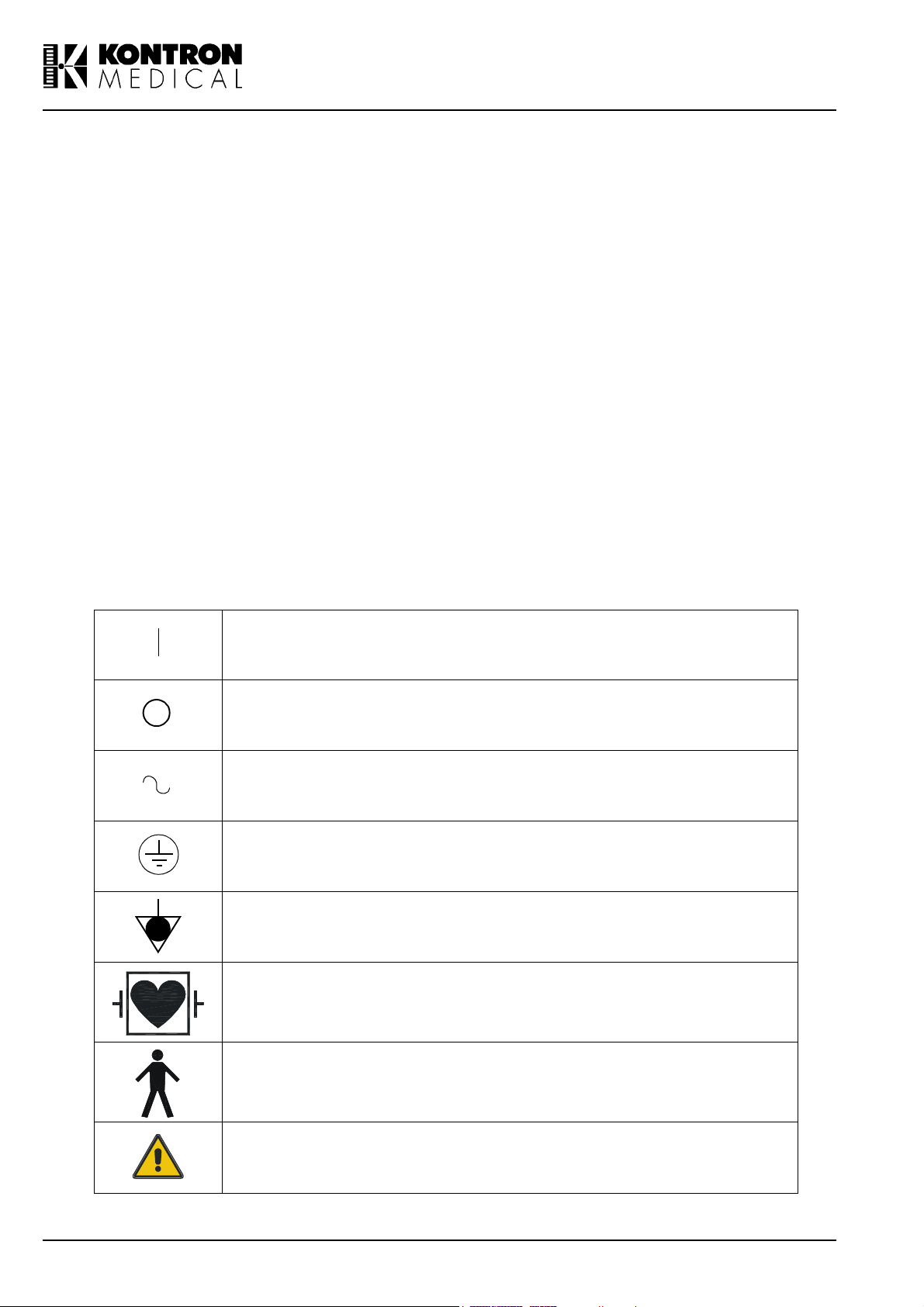
Safety Symbols
The International Electrotechnical Commission (IEC) has defined a set of graphic symbols for
use on medical electronic equipment. The following symbols are used on KONTRON MEDICAL
systems:
ON (Power)
OFF (Power)
AC line input
Protective earth (ground)
Equalization potential terminal
Type CF isolated E.C.G input, defibrillator proof (IEC 601 - 1)
Type B equipment (IEC 601 - 1)
This symbol generally means "Attention". Please consult the equipment documentation carefully before using any function labelled
with this symbol
xx SIGMA 110/SIGMA 330 15.10.01
Page 23

III.2.2. Environmental Safety
Electro-Magnetic Compatibility
This system complies with the EN60601-1-2 (Electro-Magnetic Compatibility). It is a Class B
device.
Ultrasound units are designed to receive radio frequency (RF) energy and are, therefore, susceptible to other RF sources. As an example, other medical devices, information technology
products or TV/Radio transmitters may all cause interference with the ultrasound system.
In the presence of RF interference, the physician must evaluate the image degradation and its
diagnostic impact.
Electrostatic discharge (ESD)
An electrostatic discharge is a short transient current flow. It may happen if electrostatically
charged people touches a part of ultrasound system. ESD may causes white or black dots in
2D or TM mode, coloured dots in CFM and can be heard or seen as dots in Doppler mode.
The effects created by ESD are not at all correlated with the ultrasound information. There-
fore, they may be well differentiated from the true ultrasound echo.
Burst
Bursts are short transient pulses on the mains power line. They may cause white or black
dots in 2D or TM mode, coloured dots in CFM and can be heard or seen as dots in Doppler
mode. The effects created by bursts are not correlated with the ultrasound information. There-
fore, they may be well distinguishable from the true ultrasound echo.
Immunity restriction
Electromagnetic fields in the environment of the ultrasound system may cause white or black
patterns in 2D or TM mode, coloured patterns in CFM and can be seen as horizontal lines in
Doppler mode. Especially in the Doppler modes (CW and PW), some lack of immunity may
be observed in a narrow frequency band of 20 kHz at the used frequency and its multiples.
Typically, the transducer acts like the reception antenna and the effects are stronger when it is
applied to patient. In any case, the effects are not correlated with the ultrasound information;
therefore, they may be well distinguishable from the true ultrasound echo.
Electro-Surgical Units (ESUs)
Electro surgical units or other devices that introduce radio frequency electromagnetic fields or
currents into the patient, may interfere with the ultrasound image. An electro surgical device in
use during ultrasound imaging will greatly distort the 2D image and render Doppler modalities
useless.
Information about Reusing/Recycling
In this system, the packing materials are reusable and recyclable; the unit casings (plastic) and
most of the cart components (plastic) are also recyclable.
The SIGMA 110 and SIGMA 330 contains electronic boards, batteries and tubes. Before you dispose the system, these boards, batteries and tubes must be removed and discarded according
to local regulations or recycled where facilities exist. Contact your local KONTRON MEDICAL
company or agent for further informations.
For battery disposal contact your local waste disposal facility.
15.10.01 GENERAL INFORMATION xxi
Page 24

III.2.3. Biocompatibility and Infection Control
Item s i n co ntact wi th p ati en t
The probe and electrode materials that are in contact with patients, comply with the European
applicable requirements (EN10993). No negative reactions to these materials have been
reported.
Note
KONTRON probes and electrodes do NOT contain Latex.
Infection Control
Since probes and electrodes are intended to be used on intact skin, the use of this system has a
very limited probability of being able to propagate infections; basic procedures as described later
in this manual are sufficient for infection control.
III.2.4. Ultrasound Safety
In trod u ction
KONTRON MEDICAL has adopted the more recent requirements and recommendations established by the USA Food and Drug Administration and by the American Institute for Ultrasound in
Medicine. The SIGMA 110/330 therefore, equipped with the Acoustic Output Display feature to
provide the user with real-time, on-line information on the actual power of the system.
The following sections describe the rationale of this methodology. KONTRON MEDICAL recommends the use of the ALARA principle (see below), which is extensively covered in this manual.
Additionally to this operator manual you get the AIUM manual "Medical Ultrasound Safety" which
covers the following topics more in detail: Bioeffects and biophysics, prudent use and implementing ALARA. Read it carefully before using the SIGMA 110/330.
Clinical Safety
In the USA, in more than three decades of use, there has been no report of injury to patients or
operators from medical ultrasound equipment.
Ameri can In stitute for U ltrasound in Medicine (AIU M)
Statement on Clinical Safety: October 1 982, Revised March 1 993 and October 1 993
Diagnostic ultrasound has been in use for over 25 years. Given its known benefits and recognized efficacy for medical diagnosis, including use during human pregnancy, the American Institute of Ultrasound in Medicine herein addresses the clinical safety of such use:
No confirmed biological effects on patients or instrument operators caused by exposure at
intensifies typical of present diagnostic ultrasound instruments have been reported.
Although the possibility exists that such biological effects may be identified in the future,
current data indicate that the benefits to patients deriving from the prudent use of diagnostic
ultrasound outweigh the risks, if any, that may be present.
xxii SIGMA 110/SIGMA 330 15.10.01
Page 25

The ALAR A (As Low As Reasonably Achievable) principle is the guideline for prudent use; dur-
ing an exam, the user should use for the shortest duration the least amount of acoustic output to
obtain the necessary clinical information for diagnostic purposes.
Ultrasound Bioeffects
Although diagnostic ultrasound has an excellent history of safety, it has been known for a long
time that ultrasound, at certain levels, can alter biological systems.
The AIUM Bioeffects Committee describes two fundamental mechanisms by which ultrasound
may induce biological effects: non-thermal or mechanical mechanisms and thermal effects.
Non-thermal bioeffects, also, referred to as mechanical bioeffects, seem to be caused by the
alternate expansion and contraction of tissue induced when ultrasound pressure waves pass
through or near gas. The majority of these non-thermal interactions, also known as cavitation,
deal with the generation, growth, vibration and possible collapse of micro bubbles within the tissue. The occurrence of cavitation depends on a number of factors, such as the ultrasonic pressure and frequency, the ultrasonic field (focused or unfocused, pulsed or continuous), the nature
and state of the tissue and boundaries. Mechanical bioeffects are a threshold phenomenon,
occurring only when a certain level of output is exceeded. However, the threshold level varies
depending on the tissue. The potential for mechanical effects is thought to increase as peak rarefactional pressure increases, but decrease as the ultrasound frequency increases.
Although there have been no adverse mechanical bioeffects in humans from diagnostic ultrasound exposure, it is not possible to specify thresholds at which cavitation will occur in mammals.
Therm al Bi oeffects are the rise in temperature of tissue when exposed to acoustic energy. The
acoustic energy is absorbed by body tissue; absorption is the conversion of this energy into heat.
If the rate of energy deposition in a particular region exceeds the ability to dissipate the heat, the
local temperature will rise. The rise in temperature will depend on the amount of energy, the volume of exposure, and the thermal characteristics of the tissue.
On-Screen Real-Time Acoustic Output Display
Until recently, application-specific output limits established by the USA Food and Drug Administration (FDA) and the users knowledge of equipment controls and patient body characteristics
have been the means of minimizing exposure. Now, more information is available through a new
feature, named the Acoustic Output Display. The Output Display provides users with information
that can be specifically applied to ALARA. It eliminates some of the guess work and provides
both an indication of what may actually be happening within the patient (i.e. the potential for bioeffects), and what occurs when system control settings are changed. This makes it possible for
the user to get the best image possible while following the ALARA principle and thus to maximize
the benefits/risks ratio.
The SIGMA 110/330 incorporates a real-time acoustic output display according to the AIUM/
NEMA Standard for Real-Time Display of Thermal and Mechanical Acoustic Output Indices on
Diagnostic Ultrasound Equipment publication, adopted in 1992 by both institutions. This Output
Display Standard is intended to provide on-screen display of these two indices, which are related
to ultrasound thermal and cavitation mechanisms, to assist the user in making informed risk (i.e.
patient exposure) / benefit (diagnostically useful information) decisions. Considering the type of
15.10.01 GENERAL INFORMATION xxiii
Page 26

exam, patient conditions and the case study level of difficulty, the system operator decides how
much acoustic output to apply for obtaining diagnostically useful information for the patient; the
thermal and mechanical indices real-time display is intended to provide information to the system
operator throughout the examination so that exposure of the patient to ultrasound can be reasonably minimized while maximizing diagnostic information.
For systems with an Output Display, the FDA currently regulates only the maximum output. The
SIGMA 110/330 has been designed to automatically default to the proper range of intensity levels for a particular application. However, within the SIGMA 110/330 limits, the user may override
the application specific limits, if clinically required. The user is responsible for being aware of the
output level that is being used. The SIGMA 110/330 real-time output display provides the user
with relative information about the intensity level.
The Mechanical Ind ex
The Mechanical Index (MI) is defined as the Peak Rarefactional Pressure in MPa (derated by a
tissue attenuation coefficient of 0.3 dB/cm/MHz) divided by the square root of the probe central
frequency in MHz.
With the MI, the user can keep the potential for mechanical bioeffects as low as reasonably
achievable while obtaining diagnostically adequate images. The higher the index, the larger the
potential. However, there is no level that indicates when Bioeffects is actually occurring: The
Index is not intended to give an alarm but are an aid in implementing the ALARA principle.
The Th erm al I ndex
The purpose of the Thermal Index (TI) is to keep the user aware of conditions that may lead to a
temperature rise under certain defined assumptions. It is the ratio between the total acoustic
power to the power required to raise tissue temperature by 1°C, estimated on Thermal Models.
There are currently three Thermal Indices (each based on a specific Thermal Model) used to
estimate temperature rise whether at the surface, within the tissues, or at the point where the
ultrasound is focusing on bone:
1. The Soft Tissue Thermal Index (TIS) provides information on temperature increase within soft
homogeneous tissue.
2. The Cranial Bone Thermal Index (TIC) indicates temperature increase of bone at or near the
surface, as may occur during a cranial exam.
3. The Bone Thermal Index (TIB ) provides information on temperature increase of bone at or
near the focus after the beam has passed through soft tissue.
As with the Mechanical Index, the Thermal Indices are relative indicator of temperature rise: a
higher value represents a higher temperature rise; they indicate that the possibility for an
increase in temperature exists and they provide a relative magnitude that can be used to implement ALARA.
The SIGMA 1 1 0/330 Acoustic Outpu t Display
xxiv SIGMA 110/SIGMA 330 15.10.01
Page 27

The SIGMA 110/330 displays the Acoustic Output Indices during live scanning to the right of the
screen, together with the transmit power setting and other technical data. The following abbreviations are used:
I n d ex A b b r ev i at i o n
Mechanical Index MI
Soft Tissue Thermal Index TIS
Cranial Bone Thermal Index TIC
Bone Thermal Index TIB
The Output Display is organized to provide meaningful information to implement ALARA without
distracting the user with unnecessary data. Each time a user selects a new probe a choice of
applications is provided (Radio, Vasc., Ob/Gyn, Cardio); depending on the selection, the system
will default the appropriate indices.
Note
Index values below 0.4 are displayed by this system as <0.4. Indices are displayed in 0.2
increments
To optimize ALARA, index values equal or higher than 0.4 are displayed even if the maximal index value does not exceed 1.0.
The SIGMA 110/330 does not provide combination modes (i.e. modes used simultaneously,
such as real-time 2D and Doppler), but can display a tracing (Doppler or TM-Mode) with a
reference 2D (frozen or periodically updated). The index for the active mode is indicated.
Th e SI G MA 1 1 0/330 Ou tp u t Defau lt S etti n gs
System default settings depend upon the probe, the mode of operation and the application which
is selected after selecting a probe. The SIGMA 110/330 defaults the transmit power to obtain output levels that are below the historic Ispta limits established by the FDA for the selected application.
Methodology and Accuracy of Display
The displayed indices values must be interpreted as relative information to help the user to
achieve the ALARA principle.
Initial data are derived from laboratory measurements based on the AIUM standard. Then the
indices are calculated beginning from these measurements according to the AIUM/NEMA
Standard for Real-Time Display of Thermal and Mechanical Acoustic Output Indices on Diagnostic Ultrasound Equipment publication. Many of the assumptions used for measurements and
calculation are conservative in nature. The measured water tank values are derated using the
conservative attenuation coefficient established by the FDA (0.3 dB/cm/MHz). Over-estimation of
actual In-Situ exposures is thus part of the calculation process.
A number of factors influence the estimation of the accuracy of the displayed indices, the most
significant ones being the variability between probes and the laboratory measurements accuracy
15.10.01 GENERAL INFORMATION xxv
Page 28

(hydro phone, operator, algorithms, etc.) itself, while variability of the system pulser and efficiency is a minor contributor.
The accuracy of the measurement of the centre frequency is estimated to be ±2%, of the acoustic pressure to be ±16%, of the acoustic power to be ±10% and of the acoustic intensity to be
±32%.
The accuracy estimate, based on the variability range of probes and systems, and on the inherent modelling and the above mentioned measurements errors, ranges from ±30% for the MI
index to ±50% for the TI index.
The SIGMA 1 1 0/330 Maximum Acoustic Output
As per the AIUM standard, the tables in Appendix M: Acoustic Output Tables list the maximum TI
(Thermal Index) and MI (Mechanical Index) values for each probe and mode of operation.
The system screens display the recently adopted MI, which is now considered a better relative
indicator of non-thermal bioeffect mechanisms. The SIGMA 110/330 maximal MI is 1.9 which
FDA has recognized as equivalent to pre-amendments Isppa limits.
The SIGMA 110/330 maximum output for Ispta is limited to the preamendments FDA limit for
peripheral vascular applications, which is 720 mW/cm2.
The maximum output for a given probe can be less than the system limit, since the maximum
depends on a variety of elements (crystal efficiency, mode of operation etc.). It is normally
reached with the Vasc. setup, at minimum depth or maximum PRF and in CFM with the smallest
CFM window size.
All terms are defined in Section III.2.6, Glossary and definition of terms, on page xxviii
The SIGMA 1 1 0/330 Acoustic Output Controls
Control features may be divided into three categories:
1. controls which directly affect the intensity (direct controls)
2. controls which indirectly affect the intensity (indirect controls)
3. controls which do not affect the intensity, such as the gains and the processing curves.
Controls which directly affect the intensity:
the Application selection, which establishes the appropriate range of intensities (see Maxi-
mum Output Section)
the Energy control for Doppler modes, which allows to increase or decrease the output inten-
sity within the range of the selected application.
Controls which indirectly affect the intensity:
This category includes controls which change several aspects of the transmitted ultrasonic field
rather than the intensity. Intensity is affected because of the field variations. Each mode has its
xxvi SIGMA 110/SIGMA 330 15.10.01
Page 29

own pulse repetition frequency (PRF) and intensity level; moreover, for each mode, a number of
parameters will indirectly affect the transmitted field.
2D
The SIGMA 110/330 allows the user to set the transmit focal point which will affect the indices by
varying the beam profile. Generally, higher MIs will occur with farer focal points. If more than one
transmit focal point is activated, MI values will correspond to the zone with the largest value.
TM
In TM mode, the transmitted field is only affected by the transmit focal point and the frequency. If
M-Mode is displayed with a 2D and the 2D is updated, the system may shows always the index
for the active mode (MI for 2D, TI for TM mode)
CFM
The TI may be increased by any control which increases the system frame rate:
reducing the CFM window size
increasing the CFM PRF
Another variable factor is the CFM frequency; the outcome in terms of transmitted field is marginal and largely unpredictable.
Pu lsed Wave Dopp ler
In PW, the transmit energy is adjusted automatically when changing gatesize or PRF to be constant. Therefore the TI is constant for all settings of gatesize and PRF. The only variable factor
is the Doppler frequency; the outcome in terms of transmitted field is marginal and largely unpredictable.
Continuous Wave Doppler
In CW, the only variable factor is the Doppler frequency. Most probes provide Doppler at more
than one frequency; the outcome in terms of transmitted field is marginal and largely unpredictable. The user can vary the spectral velocity range; this does NOT, however, change the systems
PRF.
Im plementing AL ARA with the SIGMA 1 1 0/330
Prudent use implies that during an exam the user should use for the shortest time the least
amount of acoustic output to obtain the necessary clinical information for diagnostic purposes. In
other words, your goal is to keep the TI and the MI indices as low as possible for the shortest
time while obtaining the necessary clinical information.
This section does not cover the patient and technique factors which may influence the indices
such as the patient body size, the tissue perfusion characteristics, the presence or the absence
of fluid, etc.
select the appropriate application when you select the probe
15.10.01 GENERAL INFORMATION xxvii
Page 30

depending on the patient characteristics and the type of exam (see Intended Use Section)
select the appropriate probe and frequency
use the system capabilities to preset the SIGMA 110/330 to default each mode according to
your needs or specific applications; this will reduce the need for real-time interactions and
help you obtain useful images quickly thus reducing ultrasound exposure
start scanning with a low output level and optimize the focusing, the gains and all other sys-
tem adjustments; if this is not adequate for diagnostic purposes, then increase the output
level
use the Output Display feature to guide your settings; remember that the indices do not con-
sider TIME exposure: the higher your indices, the shorter should be the patient exposure
Which index when
In cardiology, vascular and general purpose (abdominal, small parts) exams MI is the primary
concern in 2D mode, while TIS is the principle index in CFM and Doppler.
In Ob/Gyn the TIB should be considered when scanning a second or third trimester fetus, while
the TIS is more reliable for earlier exams.
The TIB is a better predictor during neonatal head studies, while the TIC is more significant in
adult transcranial studies.
III.2.5. Measurement Accuracy on SIGMA 1 1 0/330
This is thoroughly discussed in Chapter 1.7.11 on page 1-49 and Chapter 1.8.13 on page 1-60.
III.2.6. Glossary and definition of terms
ÞIn Situß intensities calculations
When determining the possible effects of the ultrasound beam on tissue, the intensity encountered at the tissue site must be calculated. Because of attenuation of the beam within the body,
the intensity at the tissue site (in situ) may be 10 to 100 times less than if it was measured at
the same location in water. The amount of attenuation from experience by an ultrasound beam
as it travels through the body tissue is determined by three factors:
1. Type of tissue along the beam path
2. Frequency of the ultrasound energy
3. Distance covered by the beam
In order to achieve a conservative approximation of attenuation due to these three factors, the
FDA requires the application of the following formula:
Id = Iw exp (-0.23 a f z)
Id is the estimated In Situ intensity at the tissue site
Iw is the intensity measured in water at the distance z, measured in cm
a is the attenuation coefficient expressed in dB/cm/MHz
f is equal to the acoustic frequency in MHz of the ultrasound beam
xxviii SIGMA 110/SIGMA 330 15.10.01
Page 31

Definition of terms
The Acoustic Intensity generated by an ultrasound probe is usually described as follows:
Ispta
The Spatial Peak Time Average Intensity is an ultrasound intensity averaged over time at the
point in the acoustic field where the pulse average intensity is at maximum.
Isppa
The Spatial Peak Pulse Average Intensity is an ultrasound intensity averaged over the pulse
transmission time at a point in the acoustic field where the pulse average intensity is at maximum.
Imax
The Maximum Intensity is an average intensity during the half-cycle with the greatest amplitude
during the pulse.
Mechan ical I nd ex MI
The Mechanical Index is defined as the peak rarefactional pressure in MPa (derated by a tissue
attenuation coefficient of 0.3 dB/cm/MHz) divided by the square root of the probe central frequency in MHz.
Therm al In dex TI
The Thermal Index is the ratio between the acoustic power and the power required to raise tissue
temperature by 1°C, estimated on Thermal Models.
Peak rarefactional pressure
The Peak rarefactional pressure (pr in MPa) is temporal peak rarefactional pressure amplitude at
a specified point.
Pulse Intensity Integral
The Pulse Intensity Integral (PII) is time integral of instantaneous velocity for any specific point
and for any specific pulse, integrated over the time in which the envelope of acoustic pressure or
the envelope of hydrophone signal for the specific pulse is non-zero. It is equal to the energy fluence per pulse.
15.10.01 GENERAL INFORMATION xxix
Page 32

IV. Compliance with Standards
SIGMA 110 and SIGMA 330 systems manufactured by KONTRON MEDICAL, entirely comply
with the Council Directive 93/42/EEC of 14 June 1993 concerning medical devices, and bear the
CE Mark.
They are in compliance with
CE MDD mark
German K.V. regulation
IEC 601-1 Class 1 Type B (Electrical Safety)
IEC 1157 (Acoustic power reporting)
FDA 510 (k)
Consequently, all OEM equipment (video recorders, external TV monitors and other peripherals)
should be:
connected to the three isolated outputs provided by SIGMA 330 Expert or Excellence cart or
to wall outlets using the proper isolator (see Chapter 6.3, Accessories, on page 6-5 for
ordering).
marked with CE identification mark and be in compliance with IEC 950 or IEC 601-1 Stand-
ards.
xxx SIGMA 110/SIGMA 330 15.10.01
Page 33

1. INSTRUMENT DESCRIPTION
15.10.01 INSTRUMENT DESCRIPTION 1-1
Page 34

1-2 SIGMA 110/SIGMA 330 15.10.01
Page 35

1.1 Introduction
SIGMA 110 and SIGMA 330 are Ultrasound Diagnostic Systems intended for scanning in multiapplication. They both support 2D, TM and spectral Doppler ultrasound modes. SIGMA 330
additionally supports Colour Flow Mapping (CFM).
SIGMA 110/330 can be used in following applications:
Abdominal
Breast
Cardiology
Emergency
Endocrinology
Gastro-enterology
Gynaecology
Musculoskeletal
Neonatology
Obstetrics
Paediatrics
Small parts
Urology
Vascular
SIGMA 330 features some unique characteristics in its category:
Dual Optimization Technique (D.O.T.)
Auto-adaptive Frequency Adjustment (A.F.A.TM)
Advanced Tissue Echo Cancellation (A.T.E.C.TM)
EasyPrint
USB-Link
TM
(Option)
TM
(Option)
PW/CW spectral Doppler (Option)
CFM (Option)
Multi-frequency and Multi-technology Transducers (M.M.T.)
Up to 5 transducers simultaneously connected
Super High Frequency Transducer (S.H.F.T.)
Iris colour system for optimal rendering of echo structures
256 levels grey scale
Up to 282 images cine-loop
KIPRISM, digital storage
Ergonomic design for optimal user comfort
Remote Control
15.10.01 INSTRUMENT DESCRIPTION 1-3
Page 36

The SIGMA 110 Family features some unique characteristics in its category:
Dual Optimization Technique (D.O.T)
Auto-Adaptive Frequency Adjustment (A.F.A.TM)
Advanced Tissue Echo Cancellation (A.T.E.C.TM)
EasyPrintTM (Option)
USB-Link
TM
(Option)
Multi-frequency and Multi-technology Transducers (M.M.T.)
Up to 5 transducers simultaneously connected
Super High Frequency Transducer (S.H.F.T.)
256 levels grey scale
Ergonomic design for optimal user comfort (E.D.O.)
PW/CW spectral Doppler (Option)
Up to 282 images cine-loop (Option)
KIPRISM, digital storage
Remote Control (Option)
1-4 SIGMA 110/SIGMA 330 15.10.01
Page 37

1.2 SIGMA 110/330 Equipments
The table below shows the composition of the SIGMA 110/SIGMA 330 family.
Name Relationship
SIGMA 110 Light SIGMA 110 accepting Annular Sector probes only
SIGMA 110 Master
SIGMA 330 Master SIGMA 330 including colour monitor and Iris features
SIGMA 330 Expert
SIGMA 330 Excellence
without Frame Grabber
SIGMA 330 Excellence
with Frame Grabber
The SIGMA 110/330 systems are available in different language versions.
The following table lists the ordering reference numbers of the SIGMA 110/SIGMA 330 models.
SIGMA 110 accepting Annular Sector probes and Linear/ Convex
probes
SIGMA 330 Master with integrated cart and dual port for Linear/ Convex probes
SIGMA 330 Expert with Colour Doppler (CFM) and extended capabilities (Picture Archiving and Communication System, etc.)
SIGMA 330 Expert with Colour Doppler (CFM) and extended capabilities (3D, Picture Archiving and Communication System, etc.)
Tab l e 1 - 1 : SIGMA 110/330 family
References
Models English French German Italian Spanish Cyrillic
SIGMA 110
Light
SIGMA 110
Master
SIGMA 330
Master
SIGMA 330
Expert
SIGMA 330
Excellence
without frame
grabber board
SIGMA 330
Excellence
with frame
grabber board
480 770 483 788 483 966 484 121 484 318 484 482
482 110 485 012 485 195 485 365 485 543 485 713
482 080 485 209 485 373 485 551 485 721 485 918
482 420 483 818 483 982 484 156 484 334 484 504
483680EN 483680FR 483680GE 483680IT 483680SP 483680CY
483400EN 483400FR 483400GE 483400IT 483400SP 483400CY
Tab l e 1 - 2: Reference numbers of SIGMA 110/SIGMA 330
15.10.01 INSTRUMENT DESCRIPTION 1-5
Page 38

The following table summarizes the configurations of the SIGMA 110/SIGMA 330 models:
SIGMA 110 SIGMA 330
PRODUCT
Excellence
Light Master Master Expert
w/o FG with FG
Start-up label (SIGMA ...)
Integrated Cart 99 9
Bolero Cart Option Option Option
Probes holder set 999
Handle Option Option Option
Colour monitor, Iris features
Linear/Convex probes
Spectral Doppler
CFM+ Power+ Spectral Doppler Option Option 99
Cine Option Option 99 9 9
ECG Option Option Option Option Option
Remote Control Option Option 99 9 9
Footswitch Option Option Option 99 9
Switchbox
Repetition Monitor Option Option Option Option
PCMCIA Memory Card Flash Flash SRAM 4MB SRAM 4MB SRAM 4MB SRAM 4MB
VHS option Option Option Option Option Option Option
CONFIGURATION
Time Renting Option Option Option Option Option Option
EasyPrint Black & White
EasyPrint Color Option Option 99
USB-Link Option Option Option Option 99
Integrated compact PC and
Flat 15" LCD Monitor for PC
3D-Fetal View option Option
3D-Vascular View option
e
SonoWinlite® option
PAC S
e
SonoWinbasic® option Option Option Option Option Option Option
PAC S
KIPRISM
Cardiology features
c
f
a
d
g
110 Light 110 330 330 330 330
b
999 9 9
Option Option
Option
(external)
Option Option
Option Option Option Option Option Option
9999 9 9
9999 9 9
99 9 9
Option
(external)
99 9
99
Option
Tab l e 1 - 3: System configuration and options
a. Label displayed in the start-up or system information screens.
b. Iris features include colour gamma curves (Rainbow) and colorised screen layout (measurement, technical
data, etc.).
c. Spectral-Doppler option includes PW, CW, Cine review, Angio package and VMean / VMax traces.
d. Requires Cine option.
e. Picture Archiving and Communication Systems. Please contact your local dealer for more information.
f. The complete features of Digital Archiving are obtained with Cine option. Without Cine only the Store feature
is available.
g. Cardiology includes cardiology formats and setups, biometry and measurements, ECG display that requires
ECG module.
1-6 SIGMA 110/SIGMA 330 15.10.01
Page 39

1.3 Physical Description
The basic SIGMA 1 1 0/330 is a transportable Ultrasound unit which includes the following sub-
assemblies:
Electronic cabinet containing all electronic modules
Keyboard panel
Black and White or colour video monitor
Stereo audio system for Doppler
Video Cassette Recorder output
Black & White and colour Printer output
The SIGMA 1 1 0 Light, SIGMA 1 1 0 Master and the SIG MA 330 Master consist of the basic
SIGMA 110/330 and a transducer holder kit for two transducers and for a bottle of ultrasonic gel.
A front view of these versions and the front panel opened showing the keyboard and screen are
shown in figure 1-1, SIGMA 110 Light, Master and SIGMA 330 Master, on page 1-8.
The SIGMA 330 Expert consists of the basic SIGMA 110/330 system combined with an inte-
grated cart which provides:
Room for optional Video Cassette Recorder
Room for optional Printers
Room for accessories
Elevating column for user-adaptative height
The pedal on the base of the instrument is used to control the desired position: press the pedal to
lift up; while keeping the pedal depressed, push down the column top part to get it down.
In addition to the SIGMA 330 Expert features, the SIGMA 330 Excellence includes a flat screen
associated with an integrated personal computer for 3D imaging and patient data management.
15.10.01 INSTRUMENT DESCRIPTION 1-7
Page 40

Figure 1 -1 : SIGMA 110 Light, Master and SIGMA 330 Master
1-8 SIGMA 110/SIGMA 330 15.10.01
Page 41

Figure 1 -2: SIGMA 330 Expert
15.10.01 INSTRUMENT DESCRIPTION 1-9
Page 42

Figure 1 -3: SIGMA 330 Excellence
1-10 SIGMA 110/SIGMA 330 15.10.01
Page 43

1 .3.1 Electronic Cabinet
The electronic cabinet includes the required circuitry to perform complete functions.
Power Supply
Processor which controls the main system functions and the user interface.
Transmitter/receiver modules for both linear/convex and sector transducers.
Scan Converter
Digital processing and filtering
Spectral-Doppler
Colour Flow Mapping
1 .3.2 Control Panel
The Control Panel is connected to the main electronic board through a serial line. Its ergonomics
allows the user to communicate easily with the system.
The keyboard includes a backlight that allows the system to be used in semi-darkness.
The Control Panel includes:
23 function keys
10 menu function keys. Their current functions are displayed on the corresponding
MENU on the screen.
1 incremental potentiometer (softpot). Its current function is displayed in the correspond-
ing MENU on the screen.
1 potentiometer for 2D or TM gain adjustment.
1 potentiometer for spectral gain adjustment in CFM, PW and CW.
1 potentiometer for depth selection.
5 sliders (rectilinear potentiometers) for gain equalization.
1 alphanumerical keyboard with standard upper case characters and useful graphic
characters.
1 trackball with corresponding function keys.
1 Power ON/OFF button
1 Remote control
15.10.01 INSTRUMENT DESCRIPTION 1-11
Page 44

1.3.2.1 Keyboard
The controls located on the keyboard are listed below and shown in figure 1-4, Keyboard, on
page 1-13.
1. Remote control unit location
2. Power ON/OFF key
3. Potentiometer joined to function menus
4. Alphanumerical keys
5. MENU key
6. Menu function keys joined to menus displayed on screen
7. MENU PREVIOUS/NEXT keys
8. Time Gain Compensation (TGC)
9. Function keys
10. 2D/TM gain
11. CFM/PW/CW gain
12. Depth
13. FREEZE key
14. Validation (SET) keys joined to the trackball, 3 independent keys
15. Trackball
1-12 SIGMA 110/SIGMA 330 15.10.01
Page 45

2
1
3 4 5 6 87
9
10
11
Figure 1 -4: Keyboard
12
1315 14
15.10.01 INSTRUMENT DESCRIPTION 1-13
Page 46

1.3.2.2 Remote Control Unit
It allows the remote control for main scanning parameters, freeze and image printing.
The main advantages of the remote control are:
System control in any inadequate examination condition.
Usage in operating room, because it can be easily disinfected.
Operation in difficult environment.
Group demonstration or lesson.
7 8 9 10 13
11 12
6
5
4
3
2
1
Figure 1 -5: Remote Control Unit
The different keys available on the remote controller are the following:
1. MAGNIFY: Magnify the ultrasound image by a factor 2
2. SCROLL SP (+/-): Scrolling in Trace Modes
3. DEPTH (+/-): Depth change
4. ON/OFF: Power ON/OFF
5. BASELINE (+/-): Baseline shift in PW/CW and CFM mode
6. FREQ (+/-): Freq +/- in 2D, frequencies in PW/CW and CFM
7. VELOCITY (+/-): Velocity in PW/CW and CFM modes
8. CW: CW mode switch
9. PRINT: Equivalent to PRINT1 on the keyboard
10. 2D, CFM, PW, TM: Mode switch
11. FREEZE key
12. GAIN (+/-): 2D gain in 2D, SP gain in Doppler, CFM gain in CFM
13. Trackball keys
The 3 keys SCROLL SP, BASELINE and VE L OCI TY, access directly to the corresponding Dop-
pler parameters described in Chapter 3.7.3.2, PW Live Menu, on page 3-36. For changing the
selected parameter, use (-) and (+) keys.
1-14 SIGMA 110/SIGMA 330 15.10.01
Page 47

For example, to modify the scroll speed:
1. Press SCROLL SP key to select the parameter.
2. Press (-) key to decrease the scroll speed or press (+) key to increase it.
The DEPTH key accesses directly to the corresponding 2D parameter described in Chapter
3.7.1.2, 2D Live Menu, on page 3-28. For changing the parameter, proceed as described
above.
MAGN. and FREQ are toggle keys described in Chapter 3.7.1.2, 2D Live Menu, on page 3-28.
In PW/CW mode FREQ. corresponds directly to the frequency item displayed in the Doppler
Menu on screen described in Chapter 3.7.3.2, PW Live Menu, on page 3-36 and Chapter
3.7.4.2, CW Live Menu, on page 3-41
The (-GAIN+) key modifies the overall gain according to the active mode. Press the left side of
the key to decrease the gain or press the right side to increase it.
The trackball function of the control panel is replaced by 4 arrows and a button located in the
centre. Use the arrows for moving in the four directions and press the button for validating the
operation.
The keys PRINT, TM, 2D, SELECT, CFM, PW, CW and FREEZE, access directly to the corre-
sponding functions described in Chapter 1.4, ÚSystem ControlsÛ, on page 1-28.
The Remote Control Unit is powered by two 1.5 V batteries (see Chapter 6.3, Accessories, on
page 6-5 for ordering).
1.3.3 TV Monitor
1.3.3.1 General
SIGMA 110 units are equipped with a high quality 10" Black & White monitor to display images
and information.
SIGMA 330 units are equipped with a high quality 10" colour monitor to display images and information.
The monitor is integrated into the instrument housing.
1.3.3.2 Controls
If the image is not satisfactory, check whether all controls are in the correct position for an optimum adjustment. The location of the controls is described in figure 1-6, SIGMA 110 Light,
SIGMA 110 Master and SIGMA 330 Master front view, on page 1-17.
15.10.01 INSTRUMENT DESCRIPTION 1-15
Page 48

This page is intentionally left blank
1-16 SIGMA 110/SIGMA 330 15.10.01
Page 49

1 .3.4 Front Panel
1.3.4.1 SIGMA 110 Light, Master and SIGMA 330 Master Front View
The following items are shown in figure 1-6, SIGMA 110 Light, SIGMA 110 Master and SIGMA
330 Master front view, on page 1-17:
1. Audio volume adjustment
2. Brightness adjustment for video screen
3. Contrast adjustment for video screen
4. Loudspeakers
5. Remote control receiver
6. Location dedicated to Remote Control Unit
(Remote Control Unit is optional with SIGMA 110)
7. Video screen
8. Receptacle for bottle of gel
9. Probe holder
10. Keyboard
1
2
7
8
3
9
4
5
6
4
10
Figure 1 -6: SIGMA 110 Light, SIGMA 110 Master and SIGMA 330 Master front view
15.10.01 INSTRUMENT DESCRIPTION 1-17
Page 50

1.3.4.2 SIGMA 330 Expert Front View
The following items are shown in figure 1-8, SIGMA 330 Expert front view, on page 1-19:
1. Audio volume adjustment
2. Brightness adjustment for video screen
3. Contrast adjustment for video screen
4. Loudspeakers
5. Remote control receiver
6. Remote Control Unit
7. Keyboard
8. Cabinet for optional Video Printer
9. Cabinet for optional Video Cassette Recorder
10. Cabinet for accessories
11. Control pedal for carrying up/down the column
12. Video screen (colour monitor)
Figure 1 -7: SIGMA 330 Expert front view (closed)
1-18 SIGMA 110/SIGMA 330 15.10.01
Page 51

1
12
2
3
4
5
6
7
8
9
10
4
11
Figure 1 -8: SIGMA 330 Expert front view
15.10.01 INSTRUMENT DESCRIPTION 1-19
Page 52

1.3.4.3 SIGMA 330 Excellence Front View
The following items are shown in figure 1-9, SIGMA 330 Excellence front view, on page 1-21:
1. Additional high resolution flat screen
2. Compact personal computer integrated in the lower cabinet
1-20 SIGMA 110/SIGMA 330 15.10.01
Page 53

1
2
Figure 1 -9: SIGMA 330 Excellence front view
15.10.01 INSTRUMENT DESCRIPTION 1-21
Page 54

1.3.5 Rear Panel
1.3.5.1 SIGMA 330 Expert Rear Panel
1. Fuses (Electronic cabinet - top part)
2. Switch ON/OFF (Electronic cabinet - top part)
3. Mains plug (Electronic cabinet - top part)
4. Equalization potential terminal (Chassis Ground)
5. Probe holder
6. Guide for probe cable
7. Handle
8. Connectors for Linear/Curved Probes
9. Fuses (SIGMA 110/330 cart - bottom part)
10. Switch ON/OFF (SIGMA 110/330 cart - bottom part)
11. Mains plug (SIGMA 110/330 cart - bottom part)
12. Equalization potential terminal (Chassis Ground)
13. Equalization potential terminal (Chassis Ground)
14. Connector panel
15. Connector for Doppler Pencil Probes
16. Receptacle for bottle of gel
17. Connectors for Annular Sector Probes
18. Air filter grid
19. Identification labels:
at the top: (CE mark, model, reference, serial number, revision number)
at the bottom: (model, reference, serial number)
Output power: 3 outlets for peripherals (see Chapter 2.7.2, Output Power Source, on page
2-11)
1-22 SIGMA 110/SIGMA 330 15.10.01
Page 55

1
2
19
18
3
17
16
4
5
15
6
7
6
14
8
9
13
10
11 12
Figure 1 -1 0: SIGMA 330 Expert rear panel
15.10.01 INSTRUMENT DESCRIPTION 1-23
Page 56

1.3.5.2 SIGMA 330 Excellence Rear Panel
1. Fuses (Electronic cabinet - top part)
2. Switch ON/OFF (Electronic cabinet - top part)
3. Mains plug (Electronic cabinet - top part)
4. Equalization potential terminal (Chassis Ground)
5. Probe holder
6. Guide for probe cable
7. Handle
8. Connectors for Linear/Curved Probes
9. Fuses (SIGMA 110/330 cart - bottom part)
10. Switch ON/OFF (SIGMA 110/330 cart - bottom part)
11. Mains plug (SIGMA 110/330 cart - bottom part)
12. Equalization potential terminal (Chassis Ground)
13. Equalization potential terminal (Chassis Ground)
14. Connector panel
15. Connector for Doppler Pencil Probes
16. Receptacle for bottle of gel
17. Connectors for Annular Sector Probes
18. Air filter grid
19. Identification labels:
at the top: (CE mark, model, reference, serial number, revision number)
at the bottom: (model, reference, serial number)
Output power: 3 outlets for peripherals (see Chapter 2.7.2, Output Power Source, on page
2-11)
1-24 SIGMA 110/SIGMA 330 15.10.01
Page 57

1
19
2
18
3
17
4
16
5
6
15
7
6
14
8
13
9
10
12
11
Figure 1 -1 1 : SIGMA 330 Excellence rear panel
15.10.01 INSTRUMENT DESCRIPTION 1-25
Page 58

1.3.5.3 SIGMA 110 Light, Master and SIGMA 330 Master Rear Panel
1. Fuses (see Chapter 2.7.1, Input Power Source, on page 2-10)
2. Switch ON/OFF
3. Mains plug
4. Probe holder
5. Bottle of gel receptacle
6. Equalization potential terminal (Chassis Ground)
7. Identification label (CE mark, model, reference, serial number, revision number)
8. Connector for Linear/Curved Probes (Master)
9. Air filter grid
10. Connectors for Annular Sector Probes
11. Connector for Doppler Pencil Probes
12. Connector panel
1 7
2
3
4
5
10
11
6
12
8
9
Figure 1 -1 2: SIGMA 110 Light, Master and SIGMA 330 Master rear panel
1-26 SIGMA 110/SIGMA 330 15.10.01
Page 59

1.3.5.4 Connector Panel
1 2 3 4 5 6 7 10 11 12
Figure 1 -1 3: Connector panel
Before connecting any equipment to these connectors read carefully, "Chapter III.1, Intended
Clinical Use, on page -xv" and Chapter III.2, Safety Information, on page -xviii.
1. Service connector
2. Video printer 2 remote control
3. Video printer 1 remote control
4. Remote Power Switch
5. Line Printer (parallel Port)
6. Serial Interface COM1, ECG
7. Keyboard
8. USB Port
9. Monitor
8
9
10. Video printer
11. SVHS VCR & Audio Input/Output
12. Foot switch
15.10.01 INSTRUMENT DESCRIPTION 1-27
Page 60

1.4 System Controls
Definition of the control keys shown in figure 1-4, Keyboard, on page 1-13:
1 .4.1 Alphanumeric Keys
Alphanumeric keys access to all upper case characters. Useful graphic characters are accessed
with using of the SHIFT key.
1.4.1.1 ESC Key
The ESCape key is a generic key that:
leaves any menu and return to the previous one.
aborts any string (entry and restore the previous one, if possible).
is available as often as possible to give user possibility to correct its manipulation errors.
aborts current measurement.
returns to previous study sheet or exits report when first sheet is displayed.
1.4.1.2 POWER ON/OFF Key
The POWER key switches ON or OFF system power. For Power OFF a confirmation menu is dis-
played, with a key for action aborting. This is to prevent a user manipulation error.
1.4.1.3 MENU Key
The MENU key is a toggle key displaying and hiding the menu of current functions. This menu is
depending on the current state and mode.
The (<) PREVIOUS and (>) NEXT keys located close right of the function keys, are used to
access the next/previous menu page if other menu pages are available.
0
2
MENU
F1
F6
F2
F7
F3
F8
F4
F9
F5
F10
1.4.1.4 F1 to F10 Keys
Select functions displayed in menu on the screen. If it is an action-function, the action is immediately performed.
If it is an adjustment function (this can be recognized by the symbol on screen), the user has
to make an adjustment using the potentiometer on the left of the function keys.
1.4.1.5 ID Key
The ID key calls the starting page and menu for entering new patient information, laboratory and
operator identification.
1-28 SIGMA 110/SIGMA 330 15.10.01
Page 61

1.4.1.6 PROBE
The PROBE key displays the probe MENU showing the names of the connected probes. User
can select the operating probe. On probe selection, the corresponding probe setups are loaded
and live image starts.
1.4.1.7 SETUP Key
The SETUP key displays a menu giving an user action choice on setups and preferences.
Load SETUP: replaces working parameters of current probe by parameters saved in the
SETUP.
Save SETUP: Save working parameters of current probe as preset values.
Preferences: Date & Time, Doppler Scale (m/s or kHz), Printer Selection, Patient ID, Technical Data, Cine Mode and Refresh setup.
1.4.2 Live Investigation Keys
1.4.2.1 FREEZE Key
The FREEZE key is a toggle key starting and stopping image scanning. This key is always enabled. Action on freeze key displays menu of current mode on the screen. When the report is displayed, action on freeze key exits report and displays live ultrasound image.
This key includes a relief mark for easy tactile recognition.
1.4.2.2 PRINT1 and PRINT2 Keys
The PRINT1 and PRINT2 key control video printers.
The PRINT1 key is always enabled and attached to a B&W video printer.
The PRINT2 key can be configured for colour video printer or for digital archiving (KIPRISM).
The configuration can be done with the SETUP menu.
Just before start printing, the live image is frozen and any menu removed from the screen. Just
after printing, previous system state is automatically restored.
1.4.2.3 2D Key
The 2D key sets the system in 2D mode (not all probes are 2D compatible).
1.4.2.4 TM Key
The TM key sets the system in TM mode (not all probes are 2D compatible).
1.4.2.5 CFM Key
The CFM key sets the system in CFM mode (only if linear probes are attached to the system,
mechanical probes can not be used for CFM).
This key exists only on SIGMA 330 systems + option CFM.
15.10.01 INSTRUMENT DESCRIPTION 1-29
Page 62

1.4.2.6 PW Key
The PW key sets the system in PW mode.
1.4.2.7 CW Key
The CW key sets the system in CW mode. (not all probes are CW compatible, see table i, Probe
applications, on page -xvi)
1.4.2.8 MAGNIFY Key
The MAGNIFY key is used to display an ultrasound image area magnified by a factor 2 in live or
freeze mode in 2D/CFM mode.
1.4.2.9 SELECT Key
The SE LECT key acts when 2 or more images are displayed on the screen. It freezes current
image pad, if needed, and sets in live mode the next one.
1.4.2.10 GAIN Pots
The GAIN pots change the gain of the current image (2D, TM, CFM, PW or CW). It has no action
in freeze mode. Out of the gain range limits, the system emits a sound beep to warn the user.
The gain pot which is currently active, is backlighted.
1.4.2.11 TGC Pots
The TGC (Time Gain Control) is achieved by 5 sliders (rectilinear potentiometers). Five zones
are vertically defined on the image. Each slider corresponds to one of the 5 zones and adjusts
the gain in this one. TGC acts only in 2D and TM.
1.4.2.12 DEPTH Pot
The DEPTH pot changes depth of current image (2D or TM). It has no action in freeze mode. Out
of the depth range limits, a beep sounds to warn the user.
1.4.3 Keys for Frozen Image Study
1.4.3.1 BODYMRK
The BODYMRK key displays the current body marker set according to the current medical appli-
cation
1.4.3.2 ANNOTATE
The ANNOTATE key displays or hides the annotation menu on the screen and automatically
freezes image. Annotation menu enables annotation writing, displays cursors or body markers on
the screen.
1-30 SIGMA 110/SIGMA 330 15.10.01
Page 63

1.4.3.3 MEASURE
The MEASURE key displays or hides the measurement menu on the screen and automatically
freezes ultrasound image.
1.4.3.4 REPORT
The REPORT key enters or exits the report screen and automatically freezes image. When exit-
ing report, the system returns to frozen ultrasound image display.
1.4.4 Trackball
The trackball and the 3 trackball buttons are linked together. These buttons have different functions:
Upper right keyUpper left key
Lower key
The actions associated to those keys are:
Upper left key is used to select the next available action in the action list,
Upper right key is used to select the previous available action in the action list,
Lower key is used to select the position cursor.
Action lists are managed in a circular manner: if the upper right (upper left) key is pressed and if
the current selected action is the last one (the first one) then the next selected action will be the
first (last) action of the actions list.
This convention is used for each mode except for:
Measurement,
Biometry,
Annotation,
Pop-up menus,
KIPRISM (see, Chapter 3.11.2.3, Principles of Selection and Validation, on page 3-53)
PC Mode (see, Chapter 3.20.4, PC remote control features description, on page
3-111)
Some functions are linked to the trackball:
Magnify and Zoom: moves zoomed or magnified area.
Annotation/add text: set position of cursor.
Annotation/Arrow mark: set arrow position on image.
Measures.
15.10.01 INSTRUMENT DESCRIPTION 1-31
Page 64

Patient menu.
Report.
The trackball is not attached to several functions simultaneously (except in PW live mode).
The trackball is attached to the last selected function. When the current function ends, the track-
ball attachment returns to the previous one.
1.4.4.1 Positioning of the Cursor
In any imaging mode, live and freeze, the user can move a "Position Cursor" on the screen to
point to a region of interest.
Press the lower key to display the cursor and move it using the trackball.
Press the lower key again to erase the cursor and return to previous function.
1-32 SIGMA 110/SIGMA 330 15.10.01
Page 65

1.5 Screen Layout
1 .5.1 Ultrasound Screen Layout
Colour/Grey scale
General information, date & time
Technical data
Meas. result
Zoom indicator
AFA indicator
Tilt
icon
Menu keys M1-M10
Figure 1 -1 4: Screen Layout
1.5.1.1 General information and Date & Time
In this area following information are displayed:
the laboratory references
the operator name
the patient name
the current date and time
Patient Name
print
icon
ECG message
Mag.
icon
OperatorLaboratory
Date
Body
Mark.
Time
general information fields
According to the user preferences (set in the setup menu), the content of the general information
fields can be displayed or not. These fields are set in the Patient ID form.
The content of the laboratory and the operator fields are saved in the Non Volatile RAM and displayed at each start-up.
15.10.01 INSTRUMENT DESCRIPTION 1-33
Page 66

1.5.1.2 Colour/Grey Scale
According to the current mode (2D or CFM mode), the colour and/or the grey scales are displayed on the left part of the screen. The display rules of both scales are the following:
scales are never displayed in full TM mode
scales are displayed in all the other modes when no overlapping between the scales and
the ultrasound image is possible.
scales have an height of 128 pixels in single 2D or CFM and 80 pixels in the other
modes.
The grey scale
From the 128 (CFM mode) or 256 (2D mode) ultrasound possible grey levels only 16 are
displayed in the grey scale.
Remark: in CFM mode the displayed grey scale has the half of the width of the grey scale
displayed in 2D.
The colour scale
The colour scale is only displayed in CFM modes (single or multi-pad modes) and is always
associated to the grey scale (when colour scale is displayed, grey scale also displayed). In
this mode, two different types of colour scales can be displayed.
the 128 colour levels are displayed in Power and Velocity mode
if imaging of turbulence is activated in Velocity mode 32 colour levels and 96 turbulence
levels distributed into 128 colours are displayed.
The colour baseline shift has no influence on the number of displayed colours, which is always
equal to 128 levels.
Colou r & Grey scale desi gn
+31
Baseline
Wall filter
marker
Colour Threshold
Grey scale Colour scale
Unit
-31
cm/s
Velocity
Range
1.5.1.3 Technical Data
See Chapter 1.5.3, Technical Data Area, on page 1-38.
1.5.1.4 Measurement Results
See Chapter 3.14, Measurements, on page 3-67.
1-34 SIGMA 110/SIGMA 330 15.10.01
Page 67

1.5.1.5 Icons
Four types of icons can be displayed on the SIGMA screen:
the freeze symbol icon displayed when the system is frozen
the magnify icon displayed when the 2D or CFM image is magnified
the tilt icon
the print icon
displayed with tiltable probes (6.5 EV). This symbol indicates the
current scanned part
temporary displayed when the user press on one of the two print
keys
1.5.1.6 Zoom Indicator
On the left side of the menu the range scale is drawn. This scale locates
the zoomed part of the 2D image. By moving the trackball up or down
the current displayed area will be moved and the zoom range indicator
will be modified.
Zoom range
indicator
1.5.1.7 ECG
Menu and ECG pads are always displayed one above the other. The menu is always displayed.
Menu
The colour of the ECG trace is CYAN with a colour monitor and WHITE with a B/W monitor.
1.5.1.8 Auto Frequency Adjustment (AFA)
The Auto Frequency Adjustment marker (A.F.A.) shows the current ultrasound
working frequency bandwidth of the transducer in 2D. This working frequency
5
MHz
bandwidth depends on actual selected scan depth and on the Freq+/Freq- setting.
For each transducer, depth and frequency setting, A.F.A selects the optimal frequency bandwidth of the transducer.
A.F.A. is available in single 2D mode and Freeze mode.
AFA display is selectable in the Preferences Menu.
15.10.01 INSTRUMENT DESCRIPTION 1-35
1
MHz
Page 68

1.5.2 Menu
1.5.2.1 Function Key Menu
Function Keys on the keyboard are named F1 to F10 and Menu Items on the screen M1 to M10
to get understanding of the following description easier.
MP, as Menu Potentiometer, is for the incremental potentiometer.
MK is for the MENU key.
(<) is for the PREVIOUS key
(>) is for the NEXT key.
Function Keys F1 to F10 are respectively attached to the corresponding Menu Items
M1 to M10 (e.g. pressing F1 acts on M1)
0
2
MENU
F1
F6
F2
F7
F3
F8
F4
F9
F5
F10
Figure 1 -1 5: Function Keys
A specific menu exists for each mode. The current menu is automatically displayed when entering mode. For example, pressing 2D key enters 2D mode and displays 2D menu. MK key is used
to display or hide menu. (<) (>) keys are used to access previous/next menu page when more
than one is available.
There are two types of displayed menu: single or double.
Single Menu is displayed on 1 line and consists of 5 Menu Items M1 to M5.
M1 M2 M4 M5M3
F1
F2
F3
F4
F5
F1
F2
F3
F4
F5
Figure 1 -1 6: Single Menu Display
For Single Menu the Fi and Fi' keys have the same action. Press indifferently F1 or F1' to select
M1 menu item.
Double Menu is displayed on 2 lines and consists of 10 Menu Items M1 to M10.
1-36 SIGMA 110/SIGMA 330 15.10.01
Page 69

M1 M2 M4
M3
M5
F1
F6
M7 M6
F2
F7
M8 M9 M10
F3
F8
F4
F9
F5
F10
Figure 1 -1 7: Double Menu Display
1.5.2.2 PopUp Menu Used for Labels and Body markers
When activating label or body marker menu, a list is displayed in place of the technical and
measurement data. More details on labels and body marker management are available in
Appendix L, Body Markers, on page 7-111
15.10.01 INSTRUMENT DESCRIPTION 1-37
Page 70

1.5.3 Technical Data Area
This chapter describes technical data of SIGMA 110/330 in the different modes.
In multi-pad mode, the common parameters (i.e. Gamma, Smooth, ...) are the ones of the active
pad.
1.5.3.1 Technical Data Formats
Most of parameter values are preceded by a character label so that the user can easily identify
their meaning. In the following sections the different value formats are described: xx means that 2
characters are displayed.
Non labelled data
Probe: probe name (including its working frequency).
Application: the probe medical application.
Sub-Application in CFM mode1: name of the selected CFM Sub-Application (Liver &
Vein, Kidney, Abdom. Artery, Periph. Artery, Periph. Vein and Fetal Heart) or the scanning method (Scan Fast or Scan Normal in Cardio).
Depth: xx cm
Quality: Freq+ or Freq-
Doppler frequency (SPFreq): x MHz
Doppler mode: CW or PW
CFM frequency (CFMFreq): x.xMH z
Frame rate in 2D and CFM mode: xx fps
Labelled data
2D Gain: BGainxx
Gamma: Gamma x
Rainbow: Rainb x
Enhance: Enh x
Reject: Rej x
Smooth: Smoothx
Zoom Factor: Mag x.x
Gate size: Gatexxmm
Spectral Wall filter: WxxxxH z
Vector: Ve c + x x °
Doppler Gain: DGainxx
Spectral Energy: En -xxdB
CFM Gain: CGainxx
Resolution: Res Low, Res Med or Res Hi
Persistence: Pers x
1. The parameter Sub-application is different from the biometry Medical Application. The later is only relevant
to annotation, body marker, measurement and biometry modules.
1-38 SIGMA 110/SIGMA 330 15.10.01
Page 71

Colour Map: ColMapx
CFM Energy: En -xxdB
Thermal Index1: TISx. x or TIB x. x (or MI x.x when the probe is a
pencil probe or TIC x.x when the probe is a TCD2
probe).
Mechanical Index: MI xx.x
1.5.3.2 2D and [2D]/TM Technical Data
The techdata for the 2D and [2D]/TM modes are organized as described below:
Probe
Depth
Quality
Enhance
Gamma
Zoom Factor
TI/MI
Probe
xx cm
Freq+
Enh x
Gamma x
Mag x.x
TI xx.x
Appl. name
BGainxx
Smooth x
Rej x
Rainb x
xx fps
Application
2D Gain
Smooth
Reject
Rainbow
Frame Rate
The Zoom Factor field is optional: it contains the zoom or the magnify factor and will only be displayed if Mag or Zoom is on.
1.5.3.3 2D/[TM] Technical Data
These ones contains the 2D data (except the Zoom Factor) and the TM data:
Probe
Depth
Quality
Enhance
Gamma
TI/MI
Probe
xx cm
Freq+
Enh x
Gamma x
TI xx.x
Appl. name
BGainxx
Smooth x
Rej x
Rainb x
xx fps
Application
2D Gain
Smooth
Reject
Rainbow
Frame Rate
1.5.3.4 TM Technical Data
In this mode, only the information relevant to the TM single pad are displayed:
Probe
Depth
Quality
Enhance
Gamma
TI/MI
Probe
xx cm
Freq+
Enh x
Gamma x
TI xx.x
Appl. name
BGainxx
Rej x
Rainb x
Application
2D Gain
Reject
Rainbow
1.5.3.5 Double 2D and Quad 2D Modes
In these modes the technical data window contains the information concerning the active image.
See Chapter 1.5.3.2, 2D and [2D]/TM Technical Data, on page 1-39.
1. Only one of the thermal or the mechanical index will be displayed at a time.
15.10.01 INSTRUMENT DESCRIPTION 1-39
Page 72

1.5.3.6 2D/SP, 2Di/SP Technical Data
These technical data contains the 2D data and also the PW ones:
Appl. name
BGainxx
Smooth x
Rej x
Rainb x
TI xx.x
DGainxx
Vec+xx°
En -xxdB
TI xx.x
a
Probe
xx cm
Freq+
Enh x
Gamma x
Mag x.x
PW
x.x MHz
WxxxxHz
Gatexxmm
Probe
Depth
Quality
Enhance
Gamma
Zoom Factor
PW/CW
SPFreq
SPWall Filter
GateSize
TIx/MI
a. Zoom mode only
b. PW mode only
c. only displayed when image is active and live
b
c
1.5.3.7 CFM and [CFM]/TM Technical Data
The most relevant CFM information are displayed here:
Probe
Sub-Application
Depth
Resolution
CFMFreq
Color Map
2D Gain
Zoom Factor
b
TIx
a
Probe
Subappl. name
xx cm
Res Low
x.x MHz
ColMapx
BGain xx
Mag x.x
TI xx.x
Appl. name
CGainxx
Pers x
xx fps
En -xxdB
Application
2D Gain
Smooth
Reject
Rainbow
Frame Rate
Doppler Gain
Vector
SP Energy
Application
CFM Gain
Persistence
Frame Rate
CFM Energy
a. only if Mag or Zoom is on
b. in live mode only
When Color Off is pressed, the 2D technical data are displayed (See Chapter 1.5.3.2, 2D and
[2D]/TM Technical Data, on page 1-39).
1.5.3.8 CFM/[TM] Technical Data
See Chapter 1.5.3.3, 2D/[TM] Technical Data, on page 1-39
1-40 SIGMA 110/SIGMA 330 15.10.01
Page 73

1.5.3.9 [CFM]/SP Technical Data
The CFM information is inserted in the 2D/SP techdata:
Probe
Sub-Application
Depth
Resolution
CFMFreq
Color Map
2D Gain
PW/CW
SPFreq.
SPWall Filter
GateSize
TI/MI
a. PW mode only
b. in live mode only
a
b
Probe
Subappl. name
xx cm
Res Low
x.x Mhz
ColMapx
BGainxx
PW
x.x MHz
WxxxxHz
Gatexxmm
TI xx.x
Appl. name
CGainxx
Pers x
xx fps
En -xxdB
DGainxx
Vec+xx°
En -xxdB
Application
CFM Gain
Persistence
Frame Rate
CFM Energy
Doppler Gain
Vector
SP Energy
When the Color Off key is pressed, the 2D/SP technical data are displayed (Chapter 1.5.3.6,
2D/SP, 2Di/SP Technical Data, on page 1-40).
1.5.3.10 CFM/[SP] Technical Data
Chapter 1.5.3.6, 2D/SP, 2Di/SP Technical Data, on page 1-40
15.10.01 INSTRUMENT DESCRIPTION 1-41
Page 74

1.6 Display Modes
1.6.1 2D Modes
2D (si n gle 2D) 2D+ 2D (dual) Qu ad 2D
zoomed
area
zoomed
image area
magnified
zone
Mech anical zoom
1 .6.2 TM Modes
Magnified 2D
Figure 1 -1 8: 2D Display Modes
2D or CF M+ TM
Figure 1 -1 9: TM Display Modes
Linear zoom
only the zoomed area is displayed
TM
1-42 SIGMA 110/SIGMA 330 15.10.01
Page 75

1.6.3 CW and PW Modes
2D+ CW
2D or CF M+ PW
2Di+ CW
2Di or CF Mi+ PW
Figure 1 -20: CW and PW Display Modes
Remark: the CFM+CW modes are not available because the CFM is only possible with linear
probes and the CW mode only with mechanical or pencil probes.
1 .6.4 CFM Formats
CFM
only the zoomed areas are displayed
Linear zoom
Magnified CFM
magnified
zone
Figure 1 -21 : CFM Display
These formats are only available for linear transducers. It is composed of 2 images displayed one
over the other: the 2D image (on the back) and the Colour Flow Mapping image (on the front)
15.10.01 INSTRUMENT DESCRIPTION 1-43
Page 76

1.7 SIGMA 1 10 Technical Specifications
1.7.1 General
The SIGMA 110 is a 2D, TM and spectral Doppler transportable ultrasound scanner for general
purpose applications:
Abdominal
Breast
Cardiology
Emergency
Endocrinology
Gastro-enterology
Gynaecology
Obstetrics
Paediatrics
Small parts
Musculoskeletal
Neonatology
Urology
Vascular
SCANNING TECHNIQUES
Electronic linear scanning
Electronic convex scanning
Annular array sector scanning
Doppler Pencil probes
DISPLAY MODES
Real time 2D (B-Mode) display modes:
Single 2D format
Double 2D format
Quad 2D format
2D panoramic zoom (for mechanical probes only)
2D scroll zoom (for LINEAR/CONVEX probes only)
2D magnification
TM (M-Mode) display modes:
Quasi Duplex 2D + TM: 2D (50% screen) + TM (50% screen)
Full screen TM
CW display modes:
Quasi Duplex 2D + CW: 2D (50% screen) + CW (50% screen)
2Di (icon) + CW
PW display modes:
1-44 SIGMA 110/SIGMA 330 15.10.01
Page 77

Quasi Duplex 2D + PW: 2D (50% screen) + PW (50% screen)
2Di (icon) + PW
MONITOR
Black & White monitor, 10" diagonal
640 x 480 pixels resolution
Direct management of brightness and contrast
includes loudspeakers and control knob for volume
KEYBOARD
Six languages: English, French, German, Italian, Spanish and Russian (Cyrillic)
Backlightening of all keys and knobs
Ten software controlled function keys for menu selection
Full alphanumeric capabilities
B/W video printer remote control
Trackball for focus point setting, TM, CW/PW line steering, annotations positioning,
measurements, cine-mode review and arrow pointing
Layout removable for cleaning operation
Trackball removable for cleaning operation
INFRARED REMOTE CONTROL (option)
Ensure system control in any inadequate examination condition
Allow the remote control for scanning parameters, freeze and image printing
Dedicated place on keyboard
SCREEN LAYOUT
Patient identification field including patient name clinic name, operator name, time and
date
Technical data field showing all pertinent imaging parameters
Measurement field displaying the last ten measurement results
Menu field activated by the corresponding function key
Freeze mode indicator
Cine-loop memory index (option)
Annotation arrows and user defined annotations with trackball controlled positioning
Image orientation indicator
Over 51 body markers with scan plane indication
Dot lines for TM/CW/PW beam orientation
Real time ECG trace display
Biopsy channel indication with automatic calibration of depth, probe type, left/right
guides and angle up/down orientation
SE TTIN GS
Default settings related to the medical application and transducer for image quality opti-
mization
User settings memorized in the system as well as on a flash card
15.10.01 INSTRUMENT DESCRIPTION 1-45
Page 78

1.7.2 2D (B-Mode)
SCANNING SECTOR
Angle: 40, 45, 60, 75, 90, 110 and 140° for Annular Sector (Probe dependent)
Angle: 30, 45, 60, 75, 90 and 110° for Convex Array (Probe dependent)
Depth: 2 cm to 24 cm, up to 10 depths (Probe dependent)
Nominal frequency range: 2 to 14 MHz (Probe dependent)
FRAME RATE
Up to 200 fps (probe and medical application dependent)
Depending on depth, angle and medical application
SIGNAL PROCESSING
Large bandwidth: 1.5 - 18 MHz
Overall Gain: 32 steps
Time Gain Compensation: 5 sliders
Dynamic focusing on reception
Up to four focus zones on transmission
Automatic adjustment of reception bandwidth for each depth
Contour enhancement: 7 positions application dedicated
Dynamic range control (reject): 4 positions to increase the contrast and reduce weak
echoes
Frame filter: 4 non linear smoothing filters + OFF position
Automatic Frequency Adjustment (A.F.A.) for standard and less echogenic patient
(Freq+/Freq-)
Grey scale optimization thanks to 8 Gamma curves (probe dependent)
IMAGE PRESENTATION
Single, Double and Quad image representation
Freeze mode
Left/right
Up/Down
Video inversion
RESOLUTION
512 x 512 pixels on screen for 2D image display
256 grey levels
IMAGE MEMORY (option)
Cine Mode: up to 282 images (probe and medical application dependent)
1.7.3 TM (M-Mode)
SIGNAL PROCESSING
Same as 2D mode
IMAGING PARAMETERS
Scrolling speed:
1-46 SIGMA 110/SIGMA 330 15.10.01
Page 79

2, 3, 5, 8 sec./screen (full screen)
1, 1.5, 2.5, 4 sec./screen (2D + TM)
M LINE STEERING
Trackball controlled over complete 2D sector
DISPLAY
2D (50% screen) + TM (50% screen)
Full screen TM
IMAGE MEMORY
Cine Mode:
up to 16 trace screens in full TM
up to 5 trace screens in 2D + TM
1.7.4 Spectral Doppler Mode
AVAI L AB L E MO D E S
Steerable PW
Steerable CW
SIGNAL PROCESSING
Multi-frequency Doppler mode: 2, 3, 4 and 8 MHz (probe dependent)
Velocity range:
PW: +/-1 kHz to +/- 10 kHz
CW: +/-1 kHz to +/- 20 kHz
+/- 10 cm/sec. to +/- 3.5 m/s (PW), +/- 7.2 m/sec. (CW), full scale, depending on
probe and operating frequency
High pass wall filter: 10 cut-off frequencies adjustable between 50 to 1000 Hz
Grey scale optimization with 8 post-processing curves (probe dependent)
Spectrum gain control: 11 selections between 0 and 30 dB
120 dB dynamic range for best sensitivity
256 point FFT, computing time of 0.2 ms
Doppler transmit power control: 8 selections between 0 dB and -21 dB
Doppler angle correction: from -80 to 80 °
Scrolling speed:
2, 3, 5, 8 sec./screen (full screen)
1, 1.5, 2.5, 4 sec./screen (2D + SP)
Adjustable audio volume
PW GATE
PW gate adjustable for sample volumes between 1 and 15 mm (8 selections)
PW gate adjustable with the trackball between 0 and maxi depth of the image format
DISPLAY
2D (50% screen) + Doppler (50% screen)
2D icon + Doppler
15.10.01 INSTRUMENT DESCRIPTION 1-47
Page 80

Base line shift: 9 positions for optimal signal display, avoiding spectrum aliasing
V
V
real time trace display
MEAN
and V
MAX+
MAX-
real time trace display
Quasi duplex automatic refresh: 4 levels, according to scrolling speed
IMAGE MEMORY
Cine Mode:
up to 16 trace screens in full Doppler
up to 5 trace screens in 2D + Doppler
ACOUSTIC POWER OUTPUT
Fulfils acoustic output display standards
Complies with FDA acoustic output limits
Automatic power output adjustment versus medical application for optimal Doppler per-
formance (ALARA)
User selectable Doppler transmit power attenuation:
8 positions between 0 dB and -21 dB
1.7.5 Digital Archiving: KIPRISM
Digital archiving on Memory Card: the number of ultrasound images which can be
stored, is depending on memory card capacity
up to 32 images on 4 megabytes memory card
up to 64 images on 8 megabytes memory card
etc.
Transfer on Personal Computer via memory card (PCMCIA standard, DOS format)
1.7.6 ECG Module (option)
FORMATS
for all single or dual pad formats
INPUT
Isolated input, type CF, Defibrillator proof (IEC 601-1)
through serial port, 240 x 8 bit / second, QRS trigger available
ECG Gain: 1000 (1V / 1 mV)
Heart rate: up to 180 bpm
Recovery time after defibrillator shock: > 5 sec
B MODE TRIGGER
in single and dual B mode available, trigger moment may be set by user.
For dual pad modes two independent triggers can be set.
DISPLAY and CINE REVIEW
Display trace (on video screen)
Indication of time relationship between 2D mode image and ECG trace by marker on
ECG trace. Cine review on trace modes is also available.
1-48 SIGMA 110/SIGMA 330 15.10.01
Page 81

1.7.7 EasyPrint
Direct output to inkjet printer
Compatible with HP PCL level III
TM
1.7.8 USB-Link
TM
Digital transfer of images and report text files to Personal Computer through USB cable
Compatibility: refer to Chapter 3.18.2, Compatibility, on page 3-99.
1 .7.9 Peripherals (Optional)
The following peripherals can be connected to the system:
VCR (VHS and S-VHS)
B/W video printer
Parallel DeskJet printer (PC compatible) for images (EasyPrintTM) and report printout
B/W monitor
1.7.10 Inputs/Outputs
S-VHS/VHS (including audio) input/output for VCR connection, PAL/NTSC compatible,
video playback automatically fed to the monitor
Black & White video composite output for B/W video printer connection
Double footswitch (Freeze/ Print/ Select image)
Memory card connector (PCMCIA) dedicated to software upgrade, user setup storage
and digital archiving (KIPRISM)
RGB video output for external monitor and color video printer
Parallel port for images and report printout
Serial port for peripheral devices
USB port for data transfer to PC
1.7.11 Measurement
CALIPE RS
Trackball controls the multiple callipers
Complete measurement capabilities on frozen images
2D: distance, surface and circumference of area, surface and circumference of ellipse,
angle; distance and area ratio
TM: distance, time, slope, heart rate, distance and time ratio, LV studies
PW/CW: speed gradient, frequency, time, acceleration, integral, PI & RI, RI, heart rate,
speed, gradient and time ratio
Specific measurements for OB/GYN
Up to 10 result lines on screen
15.10.01 INSTRUMENT DESCRIPTION 1-49
Page 82

ANNOTATIONS
Annotation collection
Text, arrows, body markers
PATIE N T RE POR T
Automatic selection of relevant measurement from patient report
Comprehensive report for each medical application: Radio, Vasc., Ob/Gyn, Pediatry,
Cardio.
Peripheral vascular: stenosis percentage, continuity equation, resistance index, steno-
sis index, pulsatility index, spectral broadening index, flow volume, frequency
Abdominal: volume 1 to 4 (user-defined), cardiac output, diameter, continuity equation
Pediatric: hip angles
Ob/Gyn: extensive measurements capabilities including BPD, FML, CRL, BOD, ABD,
THD, AC, GES, HC, OFD, APD, TAD, Foetal Weight, Estimated Birth Date
Cardio: left ventricular volumetry using Simpson, area length single and bi-plane formu-
las, systolic and diastolic volume using Teichholz rule, shortening fraction, myocardial
mass and mass index, left ventricular circumference, ejection fraction, cardiac output
and index, stroke volume and index, mean velocity, pressure and mean pressure gradient, pressure half time and valve area, time to peak velocity in systole, right and left ventricular ejection time and pre-ejection period, right ventricular systolic pressure,
continuity equation, QP/QS
All applications: body surface area (BSA)
ME ASUR EME NT ACCURACY
Mode: Parameters: Typical accuracy:
Distance < +/- 3%
1 mm, when 3% of the measured
2D
Angle
value is less than 1 mm
< +/- 2.5 °
Distance < +/- 1%
0.5 mm, when 1% of the meas-
TM
SP
Time
Slope
Speed
Frequency
Gradient
ured value is less than 0.5 mm
< +/- 1%
< +/- 2%
< +/- 5% of max. displayed velocity
< +/- 5% of max. displayed frequency
< +/- 10%
HR
Time
Acceleration
Heart rate computed by ECG
< +/- 1%
< 10%
+/- 1 bpm
Tab l e 1 - 4: Measurement Accuracy
1-50 SIGMA 110/SIGMA 330 15.10.01
Page 83

1 .7.1 2 Acoustic Power
SIGMA 110 complies with the FDA Standards.
Acoustic power depends on Medical Application.
I
SPPA
< 190 W/cm2 (Medical Application independent)
Im < 310 W/cm2 (Medical Application independent)
I
in situ, in mW/cm
SPTA
MEDICAL
APPLICATION
I
In situ, in mW/cm
SPTA
Accuracy of MI display: +/- 30 %
Accuracy of TI display: +/- 50 %
1.7.13 Environment
TE MPE R ATU RE
Operating temperature: 10 °C to 40 °C (50 °F to 104 °F)
Storage temperature: -20 °C to 40 °C (-4 °F to 104 °F)
HUMIDITY
Operating humidity: 30% to 80%, non condensing
2
CARDIO VASC. RADIO, OB/GYN
2
< 430 < 720 < 94
Tab l e 1 - 5: Acoustic Intensity
Storage humidity: 30% to 95%, non condensing
ATMOSPHERIC PRESSURE
Operating pressure: 700 mbar to 1060 mbar
Storage pressure: 500 mbar to 1060 mbar
ELECTRICAL SPECIFICATIONS
Input voltage: 100 - 127 V~ and 200 - 240 V~
Mains frequency: 50 - 60 Hz
Consumption: 340 VA
ELECTROMAGNETIC FIELD
Maximum field strength without degradation of performance: 1 V/m
1.7.14 Regulation and Safety
CE MDD mark
German K.V. regulation
IEC 601-1 Class 1 Type B (Electrical Safety)
IEC 1157 (Acoustic power reporting)
FDA 510 (k)
15.10.01 INSTRUMENT DESCRIPTION 1-51
Page 84

1 .7.15 Dimensions
Height: 380 mm
Width: 470 mm
Depth: 526 mm
Weight: 29 kg
1-52 SIGMA 110/SIGMA 330 15.10.01
Page 85

1.8 SIGMA 330 Technical Specifications
1 .8.1 General
The SIGMA 330 is a 2D, TM, Spectral Doppler and Color Flow Mapping ultrasound scanner for
general purpose applications:
Abdominal
Breast
Cardiology
Emergency
Endocrinology
Gastro-enterology
Gynaecology
Musculoskeletal
Neonatology
Obstetrics
Paediatrics
Small parts
Urology
Vascular
SCANNING TECHNIQUES
Electronic linear scanning
Electronic convex scanning
Annular array sector scanning
Doppler Pencil Probes
DISPLAY MODES
Real time 2D (B-Mode) display modes:
Single 2D format
Double 2D format
Quad 2D format
2D panoramic zoom (for AS probes only)
2D scroll zoom (for LINEAR/CONVEX probes only)
2D magnification
1
3D
3D-Fetal View
3D-Vascular View
TM
TM
TM (M-Mode) display modes:
Quasi Duplex 2D + TM: 2D (50% screen) + TM (50% screen)
Full screen TM
1. SIGMA 330 Excellence only
15.10.01 INSTRUMENT DESCRIPTION 1-53
Page 86

CW display modes:
PW display modes:
CFM display modes:
Colorised 2D, TM, PW & CW mode display
MONITOR
Colour monitor
Quasi Duplex 2D + CW: 2D (50% screen) + CW (50% screen)
2Di (icon) + CW
Quasi Duplex 2D + PW: 2D (50% screen) + PW (50% screen)
2Di (icon) + PW
Single CFM
Quasi Duplex CFM + PW: CFM (50% screen) + PW (50% screen)
CFMi (icon) + PW
10" diagonal
640 x 480 pixels resolution
PAL/NTSC compatible
Direct management of brightness and contrast
includes loudspeakers and control knob for volume
LCD flat panel colour monitor
15" diagonal
800 x 600 pixels resolution
KEYBOARD
Six languages: English, French, German, Italian, Spanish and Russian (Cyrillic)
Backlightening of all keys and knobs
Ten software controlled function keys for menu selection
Full alphanumeric capabilities
B/W and colour video printer remote control
Trackball for TM, CW/PW line steering, PW gate positioning, CFM colour window resiz-
ing and positioning, focus point setting, annotation positioning, measurements and cine-
mode review
Layout removable for cleaning operation
Trackball removable for cleaning operation
INFRARED REMOTE CONTROL
Ensure system control in any inadequate examination condition
1
Allow the remote control for scanning parameters, freeze and image printing
Dedicated place on keyboard
SCREEN LAYOUT
Patient identification field including patient name, clinic name, operator name, time and
date
1. SIGMA 330 Excellence only
1-54 SIGMA 110/SIGMA 330 15.10.01
Page 87

Technical data field showing all pertinent imaging parameters
Measurement field displaying the last ten measurement results
Menu field activated by the corresponding function key
Freeze mode indicator
Cine-loop memory index
Annotation arrows and user defined annotations with trackball controlled positioning
Image orientation indicator
Over 51 body markers with scan plane indication
Indication of CFM ROI position and size
Dot lines for TM/CW/PW beam orientation
Real time ECG trace display
Biopsy channel indication with automatic calibration of depth, probe type, left/right
guides and angle up/down orientation
CFM window
SE TTIN GS
Default settings related to the medical application and transducer for image quality opti-
mization
User settings memorized in the system as well as on a flash card
1.8.2 2D (B-Mode)
SCANNING SECTOR
Angle: 40, 45, 60, 75, 90, 110 and 140° for Annular Sector (Probe dependent)
Angle: 30, 45, 60, 75, 90 and 110° for Convex Array (Probe dependent)
Depth: 2 cm to 24 cm, up to 10 depths (Probe dependent)
Nominal frequency range: 2 to 14 MHz (Probe dependent)
FRAME RATE
Up to 218 fps
Depending on depth, angle and medical application
SIGNAL PROCESSING
Large bandwidth: 1.5 - 18 MHz
Overall Gain: 32 steps
Time Gain Compensation: 5 sliders
Dynamic focusing on reception
Up to four focus zones on transmission
Automatic adjustment of reception bandwidth for each depth
Contour enhancement: 7 positions application dedicated
Dynamic range control (reject): 4 positions to increase the contrast and reduce weak
echoes
Frame filter: 4 non linear smoothing filters + OFF position
15.10.01 INSTRUMENT DESCRIPTION 1-55
Page 88

Automatic Frequency Adjustment (A.F.A.) for standard and less echogenic patient
(Freq+/Freq-)
Grey scale optimization thanks to 8 Gamma curves (probe dependent)
Iris colour system
IMAGE PRESENTATION
Single, Double and Quad image representation
Freeze mode
Left/right
Up/Down
Video inversion
RESOLUTION
512 x 512 pixels on screen for 2D image display
256 grey levels
IMAGE MEMORY
Cine Mode: up to 282 images (probe and medical application dependent)
1.8.3 TM (M-Mode)
SIGNAL PROCESSING
Same as 2D mode
IMAGING PARAMETERS
Scrolling speed:
2, 3, 5, 8 sec./screen (full screen)
1, 1.5, 2.5, 4 sec./screen (2D + TM)
M LINE STEERING
Trackball controlled over complete 2D sector
DISPLAY
2D (50% screen) + TM (50% screen)
Full screen TM
IMAGE MEMORY
Cine Mode:
up to 16 trace screens in full TM
up to 5 trace screens in 2D + TM
1.8.4 Spectral Doppler Mode
AVAI L AB L E MO D E S
Steerable PW and CW
Multi-frequency Doppler modes
Spectral colorization
Automatic 2D image update when adjusting Doppler cursor position
SIGNAL PROCESSING
1-56 SIGMA 110/SIGMA 330 15.10.01
Page 89

Doppler frequencies: 2, 3, 4 and 8 MHz (probe dependent)
Velocity range:
PW: +/-1 kHz to +/- 10 kHz
CW: +/-1 kHz to +/- 20 kHz Doppler shift (PRF/2)
+/- 10 cm/sec. to +/- 3.5 m/s (PW), +/- 7.2 m/sec. (CW), full scale, depending on
probe and operating frequency
High pass wall filter: 10 cut-off frequencies adjustable between 50 to 1000 Hz
Grey scale optimization with 8 post-processing curves (probe dependent)
Spectrum gain control: 11 selections between 0 and 30 dB
120 dB dynamic range for best sensitivity
256 point FFT, computing time of 0.2 ms
Doppler transmit power control: 8 selections between 0 dB and -21 dB
Doppler angle correction: from -80 to 80 °
Scrolling speed:
2, 3, 5, 8 sec./screen (full screen)
1, 1.5, 2.5, 4 sec./screen (2D + SP)
Adjustable audio volume
Iris colour system
PW GATE
PW gate adjustable for sample volumes between 1 and 15 mm (8 selections)
PW gate adjustable with the trackball between 0 and maxi depth of the image format
DISPLAY
2D (50% screen) + Doppler (50% screen)
2D icon + Doppler
Base line shift: 9 positions for optimal signal display, avoiding spectrum aliasing
V
V
real time trace display
MEAN
and V
MAX+
MAX-
real time trace display
Quasi duplex automatic refresh: 4 levels, according to scrolling speed
IMAGE MEMORY
Cine Mode:
up to 16 trace screens in full Doppler
up to 5 trace screens in 2D + Doppler
ACOUSTIC POWER OUTPUT
Fulfils acoustic output display standard
Complies with FDA acoustic output limits
Automatic power output adjustment versus medical application for optimal Doppler per-
formance (ALARA)
User selectable Doppler transmit power attenuation: 8 positions between 0 and -21 dB
15.10.01 INSTRUMENT DESCRIPTION 1-57
Page 90

1 .8.5 Colour Doppler Modes
MODES
Steerable Color Flow Mapping (CFM) on electronic array probes
Velocity, Variance and Power mode
Automatic 2D/CFM image update when adjusting Doppler cursor position
SIGNAL PROCESSING
Multi frequency CFM mode: 2.5, 3, 5 and 6 MHz (Probe dependent and user selectable)
High pass wall filter: 6 cut-off frequencies adjustable between 44 to 4400 Hz (depend-
ant on velocity range)
Colour gain control: 32 positions between 0 and 20 dB
4 positions colour persistence
Velocity Ranges: from ± 125 Hz to ±7.5 kHz Doppler shift (PRF/2) or ±1.6 cm/s to
±2.8 m/s full scale, depending on probe, frequency and medical application
CFM WINDOW
From 10% to full length of 2D sector, trackball controlled resize
From 10% to full width of 2D sector, trackball controlled resize
Trackball control of window position within 2D sector
DISPLAY
Up to 128 colour shades, 8 levels of turbulence
8 user selectable colour maps for optimum rendering of either low velocities, high veloc-
ities and turbulence
9 positions of baseline shift
Turbulence on/off
Colour invert
Chroma maps for optimum rendering of 2D echo structures
Up to 64 frames cine memory
ACO U STI C OU TPU T
Fulfils acoustic output display standard
Complies with FDA acoustic output limits
Automatic power output adjustment versus medical application for optimal Doppler per-
formance (ALARA)
User selectable Doppler transmit power attenuation: 8 positions between 0 dB and - 21
dB
1.8.6 3D Imaging
1
2 highly intuitive user interface packages:
3D - Fetal View (2D reconstruction)
3D - Vascular View (2D and CFM reconstruction)
Quick and easy 3D acquisition
1. SIGMA 330 Excellence only
1-58 SIGMA 110/SIGMA 330 15.10.01
Page 91

Instantaneous multiplanar 3D reconstruction (MPR)
3D application specific rendering algorithms
3D segmentation tools (advanced filter operations)
Image export to standard PC file format (.bmp and .avi)
Digital archiving
1.8.7 Digital Archiving: KIPRISM
Digital archiving on Memory Card:
up to 32 images on 4 megabytes memory card
up to 64 images on 8 megabytes memory card
Transfer on Personal Computer via memory card (PCMCIA standard, DOS format)
Images in PCX format, report in TXT format
Up to 15000 color images per archiving media (640 MB)
DICOM 3.0 compatible (with PACS option)
1.8.8 ECG Module (option)
FORMATS
for all single or dual screen formats
INPUT
Isolated input, type CF, Defibrillator proof (IEC 601-1)
through serial port, 240 x 8 bit / second, QRS trigger available
ECG Gain: 1000 (1V / 1 mV)
Heart rate: up to 180 bpm
Recovery time after defibrillaror shock: > 5 sec
B MODE TRIGGER
in single and dual B mode available, trigger moment may be set by user.
For dual pad modes two independent triggers can be set.
DISPLAY and CINE REVIEW
Display trace (on video screen)
Indication of time relationship between 2D mode image and ECG trace by marker on
ECG trace. Cine review on trace modes is also available.
1.8.9 EasyPrint
TM
Direct output to inkjet printer
Compatible with HP PCL level III
1.8.10 USB-Link
TM
Digital transfer of images and report text files to Personal Computer through USB cable.
Compatibility: refer to Chapter 3.18.2, Compatibility, on page 3-99.
15.10.01 INSTRUMENT DESCRIPTION 1-59
Page 92

1.8.11 Peripherals (Optional)
All the following peripherals can be connected to the system:
VCR (VHS and S-VHS)
B/W video printer
Color video printer
Parallel DeskJet printer (PC compatible) for images (EasyPrintTM) and report printout
B/W monitor
Color monitor
1.8.12 Inputs/Outputs
S-VHS/VHS (including audio) input/output for VCR connection, PAL/NTSC compatible,
video playback automatically fed to the monitor
Black & White video composite output for B/W video printer connection
Double footswitch (Freeze / Print/Select image)
Memory card connector (PCMCIA) dedicated to software upgrade, user setup storage
and digital archiving (KIPRISM)
RGB video output for external monitor and color video printer
Parallel port for images and report printout
Serial port for peripheral devices
USB port for data transfer to PC
1.8.13 Measurement
CALIPE RS
Trackball controls the multiple callipers
Complete measurement capabilities on frozen images
2D: distance, surface and circumference of area, surface and circumference of ellipse,
angle, volume; distance and area ratio
TM: distance, time, slope, heart rate; distance and time ratio; LV studies
PW/CW: speed gradient, frequency, time, acceleration, integral, PI & RI, RI, heart rate;
speed, gradient and time ratio
CFM: velocity, velocity profile and frequency
Specific measurements for OB/GYN
Up to 10 result lines on screen
ANNOTATIONS
Annotation lists: user-defined
Text, arrows, body markers
PATIE N T R EPORT
Automatic selection of relevant measurement from patient report
Comprehensive report for each medical application: Radio, Vasc., Ob/Gyn, Pediatry,
Cardio.
1-60 SIGMA 110/SIGMA 330 15.10.01
Page 93

Peripheral vascular: stenosis percentage, continuity equation, resistance index, steno-
sis index, pulsatility index, spectral broadening index, flow volume, frequency
Abdominal: volume 1 to 4 (user-defined), cardiac output, diameter, continuity equation
Pediatric: hip angles
Ob/Gyn: extensive measurements capabilities including BPD, FML, CRL, BOD, ABD,
THD, AC, GES, HC, OFD, APD, TAD, Foetal Weight, Estimated Birth Date
Cardio: left ventricular volumetry using Simpson, area length single and bi-plane formu-
las, systolic and diastolic volume using Teichholz rule, shortening fraction, myocardial
mass and mass index, left ventricular circumference, ejection fraction, cardiac output
and index, stroke volume and index, mean velocity, pressure and mean pressure gradient, pressure half time and valve area, time to peak velocity in systole, right and left ventricular ejection time and pre-ejection period, right ventricular systolic pressure,
continuity equation, QP/QS
All applications: body surface area (BSA)
ME ASUR EME NT ACCURACY
Mode: Parameters: Typical accuracy:
Distance < +/- 3%
2D
TM
SP
CFM
1 mm, when 3% of the measured
value is less than 1 mm
Angle
< +/- 2.5 °
Distance < +/- 1%
0.5 mm, when 1% of the meas-
ured value is less than 0.5 mm
Time
Slope
Speed
Frequency
Gradient
Time
Acceleration
Velocity
Frequency
< +/- 1%
< +/- 2%
< +/- 5% of max. displayed velocity
< +/- 5% of max. displayed frequency
< +/- 10%
< +/- 1%
< 10%
< +/- 10% of the velocity range
< +/- 10% of the frequency range
HR
Heart rate computed by ECG
+/- 1 bpm
Tab l e 1 - 6: Measurement Accuracy
1 .8.1 4 Acoustic Power
The acoustic power depends on Medical Application.
I
< 190 W/cm2 (Medical Application independent)
SPPA
Im < 310 W/cm2 (Medical Application independent)
15.10.01 INSTRUMENT DESCRIPTION 1-61
Page 94

I
In situ, in mW/cm2, is shown in the table below
SPTA
MEDICAL
APPLICATION
I
In situ, in mW/cm
SPTA
Accuracy of MI display: +/- 30 %
Accuracy of TI display: +/- 50 %
1 .8.1 5 E nviron ment
TE MPE R ATU RE
Operating temperature: 10 °C to 40 °C (50 °F to 104 °F)
Storage temperature: -20 °C to 40 °C (-4 °F to 104 °F)
HUMIDITY
Operating humidity: 30% to 80%, non condensing
Storage humidity: 30% to 95%, non condensing
ATMOSPHERIC PRESSURE
Operating pressure: 700 mbar to 1060 mbar
Storage pressure: 500 mbar to 1060 mbar
CARDIO VASC. RADIO, OB/GYN
2
< 430 < 720 < 94
Tab l e 1 - 7: Acoustic Intensity
ELECTRICAL SPECIFICATIONS
Input voltage: 100 - 127 and 200 - 240 V~
Mains frequency: 50 - 60 Hz
Consumption: 340VA (main unit only), 680 VA (with integrated cart and peripherals)
E LE CTROMAGNE TIC FIE LD
Maximum field strength without degradation of performance: 1 V/m
1 .8. 1 6 R eg u lation and Safety
CE MDD mark
German K.V. regulation
IEC 601-1 Class 1 Type B (Electrical Safety)
IEC 1157 (Acoustic power reporting)
FDA 510 (k)
1 .8.1 7 Dimensions
SIGMA 330 Master
Height: 380 mm
Width: 470 mm
Depth: 526mm
Weight: 29 kg
1-62 SIGMA 110/SIGMA 330 15.10.01
Page 95

SIGMA 330 Expert
Height: 1230 mm (min.) - 1305mm (max.)
Width: 580 mm
Depth: 684 mm
Weight: 90 kg
SIGMA 330 Excellence
Height: 1230 mm (min.) - 1305 mm (max.)
Width: 580 mm
Depth: 684 mm
Weight: 103 kg
15.10.01 INSTRUMENT DESCRIPTION 1-63
Page 96

This page is intentionally left blank
1-64 SIGMA 110/SIGMA 330 15.10.01
Page 97

2. INSTALLATION
10.12.01 INSTALLATION 2-1
Page 98

2-2 SIGMA 110/SIGMA 330 10.12.01
Page 99

2.1 Installati on R eq ui rem en ts
Be sure that the site is sufficiently ventilated and do not install the instrument near any important
heat source.
In order to prevent an overheating, ensure that the ventilation openings are not covered and keep
the rear panel away from a vertical wall.
Bring the package relief as close as possible to the required operating location.
It is recommended to provide two people for removing SIGMA 110/330 from its package.
2.2 Unpacking
2.2.1 Warning
Installation must be performed by authorized KONTRON MEDICAL SAS personnel. Any attempt
by unauthorized personnel to install the instrument may invalidate the KONTRON MEDICAL SAS
warranty.
If the instrument is received in damaged conditions, request an immediate inspection by the carrier and local KONTRON MEDICAL representative.
2.2.2 Unpacking the Instrument
SIGMA 110 and SIGMA 330 instruments are packed in non-returnable packings.
2.2.2.1 SIGMA 110 Light/Master and SIGMA 330 Master
These models are packed in a cardboard box. Remove it carefully.
2.2.2.2 SIGMA 330 Expert and SIGMA 330 Excellence
The upper part (Monitor) is packed in a cardboard box. Remove it carefully.
For SIGMA 330 Excellence, the flat screen and micro-computer are packed in a separate card-
board box. Remove them carefully.
The instrument body (Cart) is packed into a wood crate:
Remove the top and side boards.
Remove the foam protecting the instrument.
Remove the instrument from the pallet.
2.3 Checking the Instruments Identification
The identification label with designation, reference number and serial number is affixed to the
rear panel (see figure 1-10, SIGMA 330 Expert rear panel, on page 1-23, figure 1-11, SIGMA
330 Excellence rear panel, on page 1-25 and figure 1-12, SIGMA 110 Light, Master and SIGMA
330 Master rear panel, on page 1-26).
10.12.01 INSTALLATION 2-3
Page 100

2.4 Checking the Delivery
Check the contents of the consignment with the delivery note that is supplied with each system. If
parts are missing or damaged, inform your local KONTRON MEDICAL representative.
Following standard parts are supplied with the instrument.
For ordering optional accessories, refer to Chapter 6.3, Accessories, on page 6-5.
Qty. Ref. Designation
1 100 250 250 ml bottle of ultrasound gel
1 411 353 Power cable (EURO/D CEE 22)
1 (or) 487 848 Power cable "North American Hospital Grade" (for US)
1 485 055 Memory card 4 MB (PCMCIA) for SIGMA 110 Light and Master
1 477 729 Memory card 4 MB - SRAM (PCMCIA) for SIGMA 330 Master
1 484 164 Memory card label
1
1
1 (or) DOC31001FR Operator Manual - French (according to system language)
1 (or) DOC31001GE Operator Manual - German (according to system language)
1 (or) DOC31001IT Operator Manual - Italian (according to system language)
1 (or) DOC31001SP Operator Manual - Spanish (according to system language)
1 (or) DOC31001CY Operator Manual - Russian (Cyrillic, according to system language)
1 483 184 Remote control Unit - English (according to system language)
1 (or) 483 176 Remote control Unit - French (according to system language)
1 (or) 483 168 Remote control Unit - German (according to system language)
1 (or) 483 141 Remote control Unit - Italian (according to system language)
1 (or) 483 133 Remote control Unit - Spanish (according to system language)
1 (or) 483 125 Remote control Unit - Cyrillic (according to system language)
2 524 204 Fuse, 5 x 20 mm, T 2 A
2 717 150 Fuse, 5 x 20 mm, T 4 A (according to line voltage)
1 487 090 Notice for NTSC fuses
1 481 033 Remote control cable for Video printer
1 862 169 Coaxial cable (75, BNC/BNC, L = 2 m)
1 487 163 USB cable (A/BM/M 15 Pts, L = 1.8 m)
2 471 059 Air filter
1 426 016 Quality Control form
DOC31001EN
462 489
Operator Manual - English (according to system language)
Medical Ultrasound Safety Guide (for US only)
a
a
a
a
a
a
b
Tab l e 2 - 1 : Supplying list for SIGMA 110 Light/Master and SIGMA 330 Master
a. only for SIGMA 330 Master
b. when USB-Link option is installed
2-4 SIGMA 110/SIGMA 330 10.12.01
 Loading...