

Page 1
If it's embedded, it's Kontron.
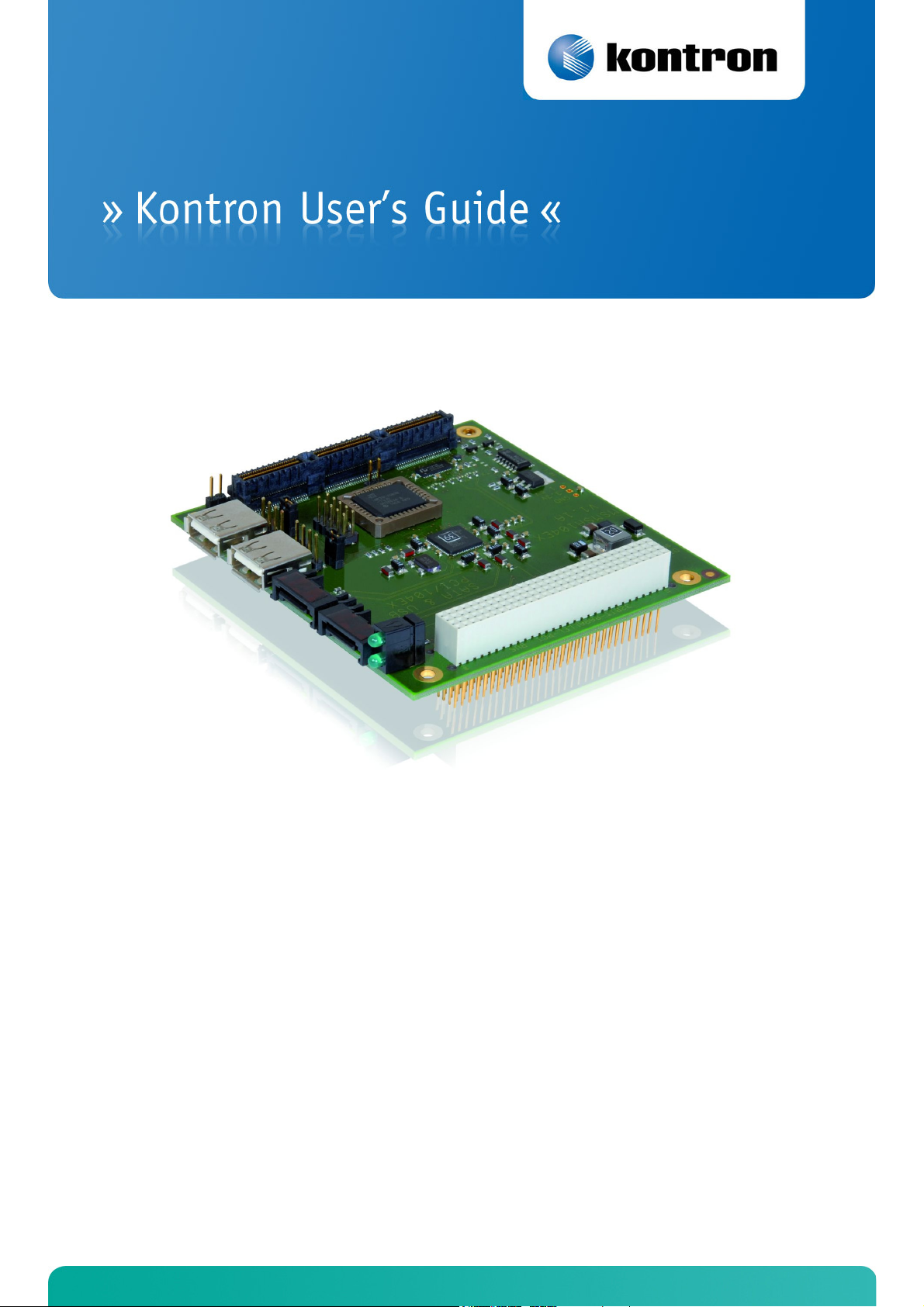
MSMSA104EX
Document Revision 100
Page 2

Page 3

» Table of Contents «
1 User Information............................................................................ 3
1.1 About this Document ...............................................................................................................3
1.2 Copyright Notice .....................................................................................................................3
1.3 Trademarks ............................................................................................................................3
1.4 Standards..............................................................................................................................3
1.5 Warranty ...............................................................................................................................3
1.6 Technical Support ...................................................................................................................4
1.7 Environmental Protection Statement ...........................................................................................4
1.8 RoHS Commitment ..................................................................................................................4
1.8.1 RoHS Compatible Product Design...............................................................................................5
1.8.2 RoHS Compliant Production Process ...........................................................................................5
1.8.3 WEEE Application ...................................................................................................................5
1.9 Swiss Quality ..........................................................................................................................5
1.10 The Swiss Association for Quality and Management Systems..............................................................6
2 Introduction ................................................................................. 7
2.1 MSMSA104EX Ordering Information.............................................................................................7
2.2 Understanding MSMSA104EX Functionality ...................................................................................7
2.3 MICROSPACE® Documentation ....................................................................................................7
2.4 MSMSA104EX Benefits..............................................................................................................7
3 Specifications................................................................................ 8
3.1 Functional Specifications ..........................................................................................................8
3.2 Dimensions............................................................................................................................8
3.3 Electrical Specifications............................................................................................................8
3.4 Environmental Specifications.....................................................................................................8
3.5 SATA300 ...............................................................................................................................9
4 SATA Controller.............................................................................10
4.1 RAID Function (if the SATA function is assembled)......................................................................... 10
4.1.1 Raid Settings ...................................................................................................................... 12
4.1.2 Useful Websites ................................................................................................................... 12
www.kontron.com
Page 4

5 MSMSA104EX Connectors & Jumpers..................................................13
5.1 Connector & Jumper Locations ................................................................................................. 13
5.1.1 Top View ............................................................................................................................ 13
5.2 Connector References ............................................................................................................ 14
5.2.1 X1/X2 SATA300 Connector ..................................................................................................... 14
5.2.2 X4/X5 USB0/USB1 Connector ................................................................................................. 14
5.2.3 X6 PCI/104-Express Bus (Top View Signal Assignment)................................................................. 15
5.2.4 X7 PCI/104-Express Bus (Bottom View Signal Assignment)............................................................ 17
5.3 Jumpers.............................................................................................................................. 19
6 Assembly Views.............................................................................20
6.1 Top View.............................................................................................................................. 20
7 Appendix A: Architecture Information................................................21
7.1 Buses ................................................................................................................................. 21
7.1.1 ISA, Standard PS/2 – Connectors ............................................................................................. 21
7.1.2 PCI/104 ............................................................................................................................. 21
7.2 General PC Architecture .......................................................................................................... 21
7.3 Ports .................................................................................................................................. 22
7.3.1 RS-232 Serial ...................................................................................................................... 22
7.3.2 Serial ATA........................................................................................................................... 22
7.3.3 USB .................................................................................................................................. 22
7.4 Programming ....................................................................................................................... 22
8 Appendix B: Document Revision History .............................................23
9 Index..........................................................................................24
www.kontron.com
Page 5

MSMSA104EX / User Information
1 User Information
1.1 About this Document
This document provides information about products from Kontron AG and/or its subsidiaries. No warranty of
suitability, purpose, or fitness is implied. While every attempt has been made to ensure that the information in this
document is accurate, the information contained within is supplied "as-is" and is subject to change without notice.
For the circuits, descriptions and tables indicated, Kontron assumes no responsibility as far as patents or other rights
of third parties are concerned.
1.2 Copyright Notice
Copyright© 2003-2010 Kontron AG
All rights reserved. No part of this document may be reproduced, transmitted, transcribed, stored in a retrieval
system, or translated into any language or computer language, in any form or by any means (electronic, mechanical,
photocopying, recording, or otherwise), without the express written permission of Kontron AG.
DIMM-PC®, PISA®, ETX®, ETXexpress®, microETXexpress™, X-board®, DIMM-IO® and DIMM-BUS® are trademarks or
registered trademarks of Kontron AG. Kontron is trademark or registered trademark of Kontron AG.
1.3 Trademarks
The following lists the trademarks of components used in this board.
» IBM, XT, AT, PS/2 and Personal System/2 are trademarks of International Business Machines Corp.
» Microsoft is a registered trademark of Microsoft Corp.
» Intel is a registered trademark of Intel Corp.
» All other products and trademarks mentioned in this manual are trademarks of their respective owners.
1.4 Standards
Kontron AG is certified to ISO 9000 standards.
1.5 Warranty
This Kontron AG product is warranted against defects in material and workmanship for the warranty period from the
date of shipment. During the warranty period, Kontron AG will, at its discretion, decide to repair or replace defective
products.
Within the warranty period, the repair of products is free of charge as long as warranty conditions are observed.
The warranty does not apply to defects resulting from improper or inadequate maintenance or handling by the buyer,
unauthorized modification or misuse, operation outside of the product’s environmental specifications or improper
installation or maintenance.
Kontron AG will not be responsible for any defects or damages to other products not supplied by Kontron AG that are
caused by a faulty Kontron AG product.
www.kontron.com 3
Page 6

MSMSA104EX / User Information
1.6 Technical Support
Technicians and engineers from Kontron AG and/or its subsidiaries are available for technical support. We are
committed to making our products easy to use and will help you use our products in your systems.
Please consult our Web site at http://www.kontron.com/support for the latest product documentation, utilities,
drivers and support contacts. Consult our customer section http://emdcustomersection.kontron.com for the latest
BIOS downloads, Product Change Notifications and additional tools and software. In any case, you can always contact
your board supplier for technical support.
1.7 Environmental Protection Statement
This product has been manufactured to satisfy environmental protection requirements wherever possible. Many of the
components used (structural parts, printed circuit boards, connectors, batteries, etc.) are capable of being recycled.
Final disposal of this product after its service life must be accomplished in accordance with applicable country, state,
or local laws or regulations. All components within this product fulfill the requirements of the RoHS (Restriction of
Hazardous Substances Directive). The product is soldered with a lead free process.
1.8 RoHS Commitment
Kontron Compact Computers AG (Switzerland) is committed to develop and produce environmentally friendly products
according to the Restriction of Hazardous Substances (RoHS) Directive (2002/95/EC) and the Waste Electrical and
Electronic Equipment (WEEE) Directive (2002/96/EC) established by the European Union. The RoHS directive was
adopted in February 2003 by the European Union and came into effect on July 1, 2006. It is not a law but a directive,
which restricts the use of six hazardous materials in the manufacturing of various types of electronic and electrical
equipment. It is closely linked with the Waste Electrical and Electronic Equipment Directive (WEEE) 2002/96/EC,
which has set targets for collection, recycling and recovery of electrical goods and is part of a legislative initiative to
solve the problem of huge amounts of toxic e-waste.
Each European Union member state is adopting its own enforcement and implementation policies using the directive
as a guide. Therefore, there could be as many different versions of the law as there are states in the EU. Additionally,
non-EU countries like China, Japan, or states in the U.S. such as California may have their own regulations for green
products, which are similar, but not identical, to the RoHS directive.
RoHS is often referred to as the "lead-free" directive but it restricts the use of the following substances:
» Lead
» Mercury
» Cadmium
» Chromium VI
» PBB and PBDE
The maximum allowable concentration of any of the above mentioned substances is 0.1% (except for Cadmium, which
is limited to 0.01%) by weight of homogeneous material. This means that the limits do not apply to the weight of the
finished product, or even to a component but to any single substance that could (theoretically) be separated
mechanically.
www.kontron.com 4
Page 7

MSMSA104EX / User Information
1.8.1 RoHS Compatible Product Design
All Kontron Compact Computers (KCC) AG standard products comply with RoHS legislation.
Since July 1, 2006, there has been a strict adherence to the use of RoHS compliant electronic and mechanical
components during the design-in phase of all KCC AG standard products.
1.8.2 RoHS Compliant Production Process
Kontron Compact Computers AG selects external suppliers that are capable of producing RoHS compliant devices.
These capabilities are verified by:
» A confirmation from the supplier indicating that their production processes and resulting devices are RoHS
compliant.
» If there is any doubt of the RoHS compliancy, the concentration of the previously mentioned substances in a
produced device will be measured. These measurements are carried out by an accredited laboratory.
1.8.3 WEEE Application
The WEEE directive is closely related to the RoHS directive and applies to the following devices:
» Large and small household appliances
» IT equipment
» Telecommunications equipment (although infrastructure equipment is exempt in some countries)
» Consumer equipment
» Lighting equipment – including light bulbs
» Electronic and electrical tools
» Toys, leisure and sports equipment
» Automatic dispensers
It does not apply to fixed industrial plants and tools. The compliance is the responsibility of the company that brings
the product to market, as defined in the directive. Components and sub-assemblies are not subject to product
compliance. In other words, since Kontron Compact Computers AG does not deliver ready-made products to end users
the WEEE directive is not applicable for KCC AG. Users are nevertheless encouraged to properly recycle all electronic
products that have reached the end of their life cycle.
1.9 Swiss Quality
» 100% Made in Switzerland
» This product was not manufactured by employees earning piecework wages
» This product was manufactured in humane work conditions
» All employees who worked on this product are paid customary Swiss market wages and are insured
» ISO 9000:2001 (quality management system)
www.kontron.com 5
Page 8

MSMSA104EX / User Information
1.10 The Swiss Association for Quality and Management Systems
The Swiss Association for Quality and Management Systems (SQS) provides certification and assessment services for
all types of industries and services. SQS certificates are accepted worldwide thanks to accreditation by the Swiss
Accreditation Service (SAS), active membership in the International Certification Network, IQNet, and co-operation
contracts/agreements with accredited partners.
www.sqs.ch
The SQS Certificate ISO 9001:2000 has been issued to Kontron Compact Computers AG in the field of development,
manufacturing and sales of embedded computer boards, embedded computer modules and computer systems. The
certification is valid for three years at which time an audit is performed for recertification.
www.kontron.com 6
Page 9

MSMSA104EX / Introduction
2 Introduction
2.1 MSMSA104EX Ordering Information
Part / Option Part Number Description
MSMSA104ex 801748 2x SATA300 with PCIe
2.2 Understanding MSMSA104EX Functionality
This MICROSPACE® PCI/104-Express expansion card has 2 SATA300 interfaces for connecting to any SATA storage
media (AD/DVD). Furthermore, 2 USB connectors are available.
» 2x SATA 300MByte/s
» PCI/104-Express
» 2x USB2
» PCI104: pass-through
» The MSMSA104EX is PCI/104-Express, version 1.0, compliant.
2.3 MICROSPACE® Documentation
This manual is written for the original equipment manufacturer (OEM) who plans to build computer systems based on
the single board MICROSPACE-PC. It is for integrators and programmers of systems based on the MICROSPACEComputer family. This manual provides instructions for installing and configuring the board and describes the system
and setup requirements. This document contains information on hardware requirements, interconnections, and
details of how to program the system. Please check the Product CD for further information and manuals.
2.4 MSMSA104EX Benefits
MICROSPACE PCI/104-Express embedded computer boards comply with the PC/104 Consortium form factor 3.55 ×
3.775 inches (90.17 × 95.89 mm) and are available in "stack through" versions.
www.kontron.com 7
Page 10

3 Specifications
Note: All information is subject to change without notice.
3.1 Functional Specifications
Bus
» Standard: PCI/104express
» Size: 32 bit PCIe
3.2 Dimensions
» Length: 90 mm
» Width: 96 mm
MSMSA104EX / Specifications
» Height: 15 mm
3.3 Electrical Specifications
Power Supply
» Working: 5 Volt / 1W
3.4 Environmental Specifications
Temperature
» Operating, standard version: -25°C to +70°C
» Operating, industrial version: -25°C to +85°C (ask Kontron Compact Computers AG)
» Non-operating (storage): -55°C to +85°C
Vibration
» 5 to 2000 Hz
Humidity
» 5% to 90% (non-condensing)
Shock
» 10 g
www.kontron.com 8
Page 11

3.5 SATA300
» Controller Silicon Image SiL3132
» Enhanced BIOS Yes
» Memory None
» Interface 2x SATA300 connectors
MSMSA104EX / Specifications
www.kontron.com 9
Page 12

MSMSA104EX / SATA Controller
4 SATA Controller
The Silicon Image Sil3132 is a two-port PCI Express to SATA controller. The Sil3132 is designed to provide multiple
port SATA connectivity with minimal host overhead and host to device latency. The Sil3132 supports a 1-lane 2.5Gb7s
PCI Express BUS and the SATA Generation 2 transfer rate of 3.0G7b (300MB/s).
4.1 RAID Function
(if the SATA function is assembled)
RAID - Redundant Array of Independent Disks:
RAID technology manages multiple disk drives to enhance I/O performance and provide redundancy in order to
withstand the failure of any individual member, without loss of data. SATA Raid provides two RAID Set types, Striped
(RAID 0), Mirrored (RAID 1), Mirroring and Striping (RAID 10) and Parity RAID (RAID 5).
Disk Striping (RAID 0)
Striping is a performance-oriented, non-redundant data mapping technique. While Striping is discussed as a RAID Set
type, it actually does not provide fault tolerance. With modern SATA and ATA BUS mastering technology, multiple I/O
operations can be done in parallel, enhancing performance. Striping arrays use multiple disks to form a larger virtual
disk. This figure shows a stripe set using three disks with stripe one written to disk one, stripe two to disk two, and so
forth. RAID 0 sets can include two, three, four or five drives. If the sizes of the disk segments are different, the
smallest disk segment will limit the size of the RAID Group.
Disk Mirroring (RAID 1)
Disk mirroring creates an identical twin for a selected disk by having the data simultaneously written to two disks. This
redundancy provides instantaneous protection from a single disk failure. If a read failure occurs on one drive, the
system reads the data from the other drive. RAID 1 sets are typically comprised of two drives, and a third drive can be
allocated as a spare in case one of the drives in the set fails. Additional drives can be configured as part of a mirrored
set, but without much added benefit. If the sizes of the disk segments are different, the smallest disk segment will
limit the overall size of RAID Group.
www.kontron.com 10
Page 13

MSMSA104EX / SATA Controller
Disk Mirroring and Striping (RAID 10)
RAID 10 combines the features of both RAID 0 and RAID 1. Performance is provided through the use of Striping (RAID
0) while adding the fault tolerance of Mirroring (RAID 1). The implementation of RAID 10 requires four drives. The
drives are assigned as two sets of mirrored pairs.
The Data is written to RAID Group A, which is mirrored (RAID 1) and provides data redundancy. Alternating blocks of
data are then striped across another RAID 1 mirrored set, shown as Set B in the figure above. This provides improved
speed.
Under certain circumstances, a RAID 10 set can sustain multiple simultaneous drive failures.
Parity RAID (RAID 5)
Parity RAID, or RAID 5, adds fault tolerance to Disk Striping by including parity information with the data. Parity RAID
dedicates the equivalent of one disk for storing parity stripes. The data and parity information is arranged on the disk
array so that parity is written to different disks. There are at least 3 members to a Parity RAID set. The following
example illustrates how the parity is rotated from disk to disk.
Parity RAID uses less capacity for protection and is the preferred method to reduce the cost per megabyte for larger
installations. Mirroring requires a 100% increase in capacity to protect the data whereas the above example using
three hard drives only requires a 50% increase. The additional required capacity decreases as the number of disks in
the group increases (i.e., 33% for four drives or 25% for five drives).
In exchange for low overhead necessary to implement protection, Parity RAID degrades performance for all write
operations. The parity calculations for Parity RAID may result in write performance that is somewhat slower than the
write performance to a single disk.
www.kontron.com 11
Page 14

MSMSA104EX / SATA Controller
Concatenated
The Concatenated mode combines multiple disks or segments of disks into a single large volume. It does not provide
any data protection or performance improvement but can be useful for utilizing leftover space on disks.
Concatenation allows the segments that make up the volume to be of different sizes.
4.1.1 Raid Settings
Please visit our website: www.kontron.com
or see
http://www.siliconimage.com/docs/SATARAID5-UserGuide_v1.30.pdf
Note Press <CTRL + S> to enter the RAID utility.
Do not press F4 because F4 is reserved for KCC's Core BIOS function!
4.1.2 Useful Websites
Working with the MSMSA104ex peripheral board, some information might be needed regarding the Intel Boot Agent
software. This information can be found at the following websites:
http://support.intel.com
http://www.intel.com/network
http://developer.intel.com
www.kontron.com 12
Page 15

MSMSA104EX / MSMSA104EX Connectors & Jumpers
5 MSMSA104EX Connectors & Jumpers
5.1 Connector & Jumper Locations
5.1.1 Top View
www.kontron.com 13
Page 16

5.2 Connector References
5.2.1 X1/X2 SATA300 Connector
Pin Signal Pin Signal
1 Ground 2 TX+
3 TX- 4 Ground
5 RX- 6 RX+
7 Ground – –
5.2.2 X4/X5 USB0/USB1 Connector
Pin Signal
1 VCC
2 USB +
3 USB -
4 GND
MSMSA104EX / MSMSA104EX Connectors & Jumpers
www.kontron.com 14
Page 17

MSMSA104EX / MSMSA104EX Connectors & Jumpers
5.2.3 X6 PCI/104-Express Bus (Top View Signal Assignment)
Pin Signal Signal Pin
1 Reserved (GPIO0) PE_RST# 2
3 3.3V 3.3V 4
5 USB1+ USB0+ 6
7 USB1- USB0- 8
9 GND GND 10
11 PEx1_1T+ PEx1_0T+ 12
13 PEx1_1T- PEx1_0T- 14
15 GND GND 16
17 PEx1_2T+ PEx1_3T+ 18
19 PEx1_2T- PEx1_3T- 20
21 GND GND 22
23 PEx1_1R+ PEx1_0R+ 24
25 PEx1_1R- PEx1_0R- 26
27 GND GND 28
29 PEx1_2R+ PEx1_3R+ 30
31 PEx1_1R- PEx1_3R- 32
33 GND GND 34
35 PEx1_1Clk+ PEx1_0Clk+ 36
37 PEx1_1Clk- PEx1_0Clk- 38
39 5V_Always 5V_Always 40
41 PEx1_2Clk+ PEx1_3Clkp+ 42
43 PEx1_2Clk- PEx1_3Clk- 44
45 CPU_DIR PWRGOOD 46
47 SMB_DAT PEx16_x8_x4_Clk+ 48
49 SMB_CLK PEx16_x8_x4_Clk- 50
51 SMB_ALERT
53 Reserved / Wake# PEG_ENA# 54
55 GND GND 56
57 PEx16_0T(8)+ PEx16_0T(0)+ / SDVO0R+ 58
59 PEx16_0T(8)- PEx16_0T(0)- / SDVO0R- 60
61 GND GND 62
63 PEx16_0T(9)+ PEx16_0T(1)+ / SDVO1G+ 64
65 PEx16_0T(9)n- PEx16_0T(1)- / SDVO1G- 66
67 GND GND 68
69 PEx16_0T(10)+ PEx16_0T(2)+ / SDVO0B+ 70
71 PEx16_0T(10)- PEx16_0T(2)- / SDVO0B- 72
73 GND GND 74
75 PEx16_0T(11)+ PEx16_0T(3)+ / SDVO0CLK+ 76
77 PEx16_0T(11)- PEx16_0T(3)- / SDVO0CLK- 78
79 GND GND 80
81 PEx16_0T(12)+ PEx16_0T(4)+ / SDVO1R+ 82
83 PEx16_0T(12)- PEx16_0T(4)- / SDVO1R- 84
85 GND GND 86
87 PEx16_0T(13)+ PEx16_0T(5)+ / SDVO1G+ 88
89 PEx16_0T(13)- PEx16_0T(5)- / SDVO1G- 90
91 GND GND 92
93 PEx16_0T(14)+ PEx16_0T(6)+ / SDVO1B+ 94
95 PEx16_0T(14)- PEx16_0T(6)- / SDVO1B- 96
97 GND GND 98
99 PEx16_0T(15)+ PEx16_0T(7)+ / SDVO1CLK+ 100
101 PEx16_0T(15)- PEx16_0T(7)- / SDVO1CLK+ 102
103 GND
+5 Volts
PSON# 52
+5 Volts
GND 104
www.kontron.com 15
Page 18

MSMSA104EX / MSMSA104EX Connectors & Jumpers
Pin Signal Signal Pin
105 SDVO_DAT (PENA#) SDVO_CLK 106
107 GND GND 108
109 PEx16_0R(8)+ PEx16_0R(0)+ / SDVO_TVCI+ 110
111 PEx16_0R(8)- PEx16_0R(0)- / SDVO_TVCI- 112
113 GND GND 114
115 PEx16_0R(9)+ PEx16_0R(1)+ / SDVO_INT+ 116
117 PEx16_0R(9)- PEx16_0R(1)- / SDVO_INT- 118
119 GND GND 120
121 PEx16_0R(10)+ PEx16_0R(2)+ / SDVO_STALL+ 122
123 PEx16_0R(10)- PEx16_0R(2)- / SDVO_STALL- 124
125 GND GND 126
127 PEx16_0R(11) PEx16_0R(3)+ 128
129 PEx16_0R(11)- PEx16_0R(3)- 130
131 GND GND 132
133 PEx16_0R(12)+ PEx16_0R(4)+ 134
135 PEx16_0R(12)- PEx16_0R(4)- 136
137 GND GND 138
139 PEx16_0R(13)+ PEx16_0R(5)+ / SDVO1_INT+ 140
141 PEx16_0R(13)- PEx16_0R(5)- / SDVO1_INT- 142
143 GND GND 144
145 PEx16_0R(14)p PEx16_0R(6)+ 146
147 PEx16_0R(14)n PEx16_0R(6)- 148
149 GND GND 150
151 PEx16_0R(15)+ PEx16_0R(7)+ 152
153 PEx16_0R(15)- PEx16_0R(7)- 154
155 GND
+12 Volts
GND 156
www.kontron.com 16
Page 19

MSMSA104EX / MSMSA104EX Connectors & Jumpers
5.2.4 X7 PCI/104-Express Bus (Bottom View Signal Assignment)
Pin Signal Signal Pin
2 PE_RST# Reserved (GPIO0) 1
4 3.3V 3.3V 3
6 USB0+ USB1+ 5
8 USB0- USB1- 7
10 GND GND 9
12 PEx1_0T+ PEx1_1T+ 11
14 PEx1_0T- PEx1_1T- 13
16 GND GND 15
18 PEx1_3T+ PEx1_2T+ 17
20 PEx1_3T- PEx1_2T- 19
22 GND GND 21
24 PEx1_0R+ PEx1_1R+ 23
26 PEx1_0R- PEx1_1R- 25
28 GND GND 27
30 PEx1_3R+ PEx1_2R+ 29
32 PEx1_3R- PEx1_1R- 31
34 GND GND 33
36 PEx1_0Clk+ PEx1_1Clk+ 35
38 PEx1_0Clk- PEx1_1Clk- 37
40 5V_Always 5V_Always 39
42 PEx1_3Clkp+ PEx1_2Clk+ 41
44 PEx1_3Clk- PEx1_2Clk- 43
46 PWRGOOD CPU_DIR 45
48 PEx16_x8_x4_Clk+ SMB_DAT 47
50 PEx16_x8_x4_Clk- SMB_CLK 49
52 PSON#
54 PEG_ENA# Reserved / Wake# 53
56 GND GND 55
58 PEx16_0T(0)+ / SDVO0R+ PEx16_0T(8)+ 57
60 PEx16_0T(0)- / SDVO0R- PEx16_0T(8)- 59
62 GND GND 61
64 PEx16_0T(1)+ / SDVO1G+ PEx16_0T(9)+ 63
66 PEx16_0T(1)- / SDVO1G- PEx16_0T(9)n- 65
68 GND GND 67
70 PEx16_0T(2)+ / SDVO0B+ PEx16_0T(10)+ 69
72 PEx16_0T(2)- / SDVO0B- PEx16_0T(10)- 71
74 GND GND 73
76 PEx16_0T(3)+ / SDVO0CLK+ PEx16_0T(11)+ 75
78 PEx16_0T(3)- / SDVO0CLK- PEx16_0T(11)- 77
80 GND GND 79
82 PEx16_0T(4)+ / SDVO1R+ PEx16_0T(12)+ 81
84 PEx16_0T(4)- / SDVO1R- PEx16_0T(12)- 83
86 GND GND 85
88 PEx16_0T(5)+ / SDVO1G+ PEx16_0T(13)+ 87
90 PEx16_0T(5)- / SDVO1G- PEx16_0T(13)- 89
92 GND GND 91
94 PEx16_0T(6)+ / SDVO1B+ PEx16_0T(14)+ 93
96 PEx16_0T(6)- / SDVO1B- PEx16_0T(14)- 95
98 GND GND 97
100 PEx16_0T(7)+ / SDVO1CLK+ PEx16_0T(15)+ 99
102 PEx16_0T(7)- / SDVO1CLK+ PEx16_0T(15)- 101
104 GND
+5 Volts
SMB_ALERT 51
+5 Volts
GND 103
www.kontron.com 17
Page 20

MSMSA104EX / MSMSA104EX Connectors & Jumpers
Pin Signal Signal Pin
106 SDVO_CLK SDVO_DAT (PENA#) 105
108 GND GND 107
110 PEx16_0R(0)+ / SDVO_TVCI+ PEx16_0R(8)+ 109
112 PEx16_0R(0)- / SDVO_TVCI- PEx16_0R(8)- 111
114 GND GND 113
116 PEx16_0R(1)+ / SDVO_INT+ PEx16_0R(9)+ 115
118 PEx16_0R(1)- / SDVO_INT- PEx16_0R(9)- 117
120 GND GND 119
122 PEx16_0R(2)+ / SDVO_STALL+ PEx16_0R(10)+ 121
124 PEx16_0R(2)- / SDVO_STALL- PEx16_0R(10)- 123
126 GND GND 125
128 PEx16_0R(3)+ PEx16_0R(11) 127
130 PEx16_0R(3)- PEx16_0R(11)- 129
132 GND GND 131
134 PEx16_0R(4)+ PEx16_0R(12)+ 133
136 PEx16_0R(4)- PEx16_0R(12)- 135
138 GND GND 137
140 PEx16_0R(5)+ / SDVO1_INT+ PEx16_0R(13)+ 139
142 PEx16_0R(5)- / SDVO1_INT- PEx16_0R(13)- 141
144 GND GND 143
146 PEx16_0R(6)+ PEx16_0R(14)p 145
148 PEx16_0R(6)- PEx16_0R(14)n 147
150 GND GND 149
152 PEx16_0R(7)+ PEx16_0R(15)+ 151
154 PEx16_0R(7)- PEx16_0R(15)- 153
156 GND
+12 Volts
GND 155
www.kontron.com 18
Page 21

5.3 Jumpers
The Jumpers for the USB0 and USB1 circuit on this product:
Default settings in bold!
Jumper Structure Open Closed
J4 USB1
Enable
Disable
MSMSA104EX / MSMSA104EX Connectors & Jumpers
J5 USB0
Enable
Attention There are only two USB ports on the PCIe bus.
If different PCI/104-Express boards with additional USB ports are being used, then the board which will
have the USB ports available must be selected.
Jumpers J4 (USB1) and J5 (USB0) enable or disable the two ports; if they are open, the USB ports are
enabled. Close these jumpers if the two USB ports are already used on another PCI/104-Express board.
It is also possible to enable one USB port on each board but be careful that USB0 is enabled on one
board and USB1 on the other board!
Disable
www.kontron.com 19
Page 22

6 Assembly Views
6.1 Top View
MSMSA104EX / Assembly Views
www.kontron.com 20
Page 23

MSMSA104EX / Appendix A: Architecture Information
7 Appendix A: Architecture Information
The following sources of information can help you better understand PC architecture.
7.1 Buses
7.1.1 ISA, Standard PS/2 – Connectors
» AT Bus Design: Eight and Sixteen-Bit ISA, E-ISA and EISA Design, Edward Solari, Annabooks, 1990, ISBN 0-
929392-08-6
» AT IBM Technical Reference, Volumes 1&2, 1985
» ISA & EISA Theory and Operation, Edward Solari, Annabooks, 1992, ISBN 0929392159
» ISA Bus Specifications and Application Notes, Jan. 30, 1990, Intel
» ISA System Architecture, Third Edition, Tom Shanley and Don Anderson, Addison-Wesley Publishing
Company, 1995, ISBN 0-201-40996-8
» Personal Computer Bus Standard P996, Draft D2.00, Jan. 18, 1990, IEEE Inc
» Technical Reference Guide, Extended Industry Standard Architecture Expansion Bus, Compaq 1989
7.1.2 PCI/104
» Embedded PC 104 Consortium
» The consortium provides information about PC/104 and PC/104-Plus technology. You can search for
information about the consortium on the Web.
» PCI SIG
» The PCI-SIG provides a forum for its ~900 member companies, who develop PCI products based on the
specifications that are created by the PCI-SIG. You can search for information about the SIG on the Web.
» PCI & PCI-X Hardware and Software Architecture & Design, Fifth Edition, Edward Solari and George Willse,
Annabooks, 2001, ISBN 0-929392-63-9.
» PCI System Architecture, Tom Shanley and Don Anderson, Addison-Wesley, 2000, ISBN 0-201-30974-2.
7.2 General PC Architecture
» Embedded PCs, Markt&Technik GmbH, ISBN 3-8272-5314-4 (German)
» Hardware Bible, Winn L. Rosch, SAMS, 1997, 0-672-30954-8
» Interfacing to the IBM Personal Computer, Second Edition, Lewis C. Eggebrecht, SAMS, 1990, ISBN 0-672-
22722-3
» The Indispensable PC Hardware Book, Hans-Peter Messmer, Addison-Wesley, 1994, ISBN 0-201-62424-9
» The PC Handbook: For Engineers, Programmers, and Other Serious PC Users, Sixth Edition, John P. Choisser
and John O. Foster, Annabooks, 1997, ISBN 0-929392-36-1
www.kontron.com 21
Page 24

MSMSA104EX / Appendix A: Architecture Information
7.3 Ports
7.3.1 RS-232 Serial
» EIA232E standard
» The EIA-232-E standard specifies the interface between (for example) a modem and a computer so that they
can exchange data. The computer can then send data to the modem, which then sends the data over a
telephone line. The data that the modem receives from the telephone line can then be sent to the computer.
You can search for information about the standard on the Web.
» RS-232 Made Easy: Connecting Computers, Printers, Terminals, and Modems, Martin D. Seyer, Prentice Hall,
1991, ISBN 0-13-749854-3
» National Semiconductor: The Interface Data Book includes application notes. Type “232” as search criteria to
obtain a list of application notes. You can search for information about the data book on National
Semiconductor’s Web site.
7.3.2 Serial ATA
Serial AT Attachment (ATA) Working Group. This X3T10 standard defines an integrated bus interface between disk
drives and host processors. It provides a common point of attachment for systems manufacturers and the system. You
can search for information about the working group on the Web. We recommend you also search the Web for
information on 4.2 I/O cables, if you use hard disks in a DMA3 or PIO4 mode.
7.3.3 USB
USB Specification
USB Implementers Forum, Inc. is a non-profit corporation founded by the group of companies that developed the
Universal Serial Bus specification. The USB-IF was formed to provide a support organization and forum for the
advancement and adoption of Universal Serial Bus technology. You can search for information about the standard on
the Web.
7.4 Programming
» C Programmer’s Guide to Serial Communications, Second Edition, Joe Campbell, SAMS, 1987, ISBN 0-672-
22584-0
» Programmer’s Guide to the EGA, VGA, and Super VGA Cards, Third Edition, Richard Ferraro, Addison-Wesley,
1990, ISBN 0-201-57025-4
» The Programmer’s PC Sourcebook, Second Edition, Thom Hogan, Microsoft Press, 1991, ISBN 1-55615-321-X
» Undocumented PC, A Programmer’s Guide to I/O, CPUs, and Fixed Memory Areas, Frank van Gilluwe, Second
Edition, Addison-Wesley, 1997, ISBN 0-201-47950-8
www.kontron.com 22
Page 25

MSMSA104EX / Appendix B: Document Revision History
8 Appendix B: Document Revision History
Revision Date Edited by Changes
100 22.Apr.2010 WAS Changed to new Kontron Corporate Design from DLAG V1.1A including title photo.
www.kontron.com 23
Page 26

9 Index
MSMSA104EX / Index
A
Architecture Information .................................. 21
Assembly Views .............................................. 20
Top View..............................................................20
B
Benefits.......................................................... 7
Bus ................................................................ 8
C
Connector References ...................................... 14
Connectors
ISA.....................................................................21
PCI/104-Express Bus ........................................15, 17
PS/2...................................................................21
SATA300..............................................................14
USB....................................................................14
Connectors & Jumpers ..................................... 13
Copyright ........................................................ 3
Corporate Offices ............................................ 26
D
J
Jumpers ........................................................19
Jumpers for the LAN1000 ..................................19
O
Ordering Information ........................................ 7
P
PCI/104.........................................................21
Ports.............................................................22
Power Supply................................................... 8
Programming..................................................22
R
RAID Function.................................................10
Concatenated .......................................................12
Disk Mirroring.......................................................10
Disk Mirroring and Striping .....................................11
Disk Striping ........................................................10
Parity RAID ..........................................................11
Raid Settings ..................................................12
Dimensions...................................................... 8
Document Revision History ............................... 23
Documentation..............................................3, 7
E
Environmental Protection ................................... 4
F
Functionality ................................................... 7
H
Humidity......................................................... 8
RoHS ............................................................. 4
RS-232 Serial..................................................22
S
SATA Controller ...............................................10
SATA300......................................................... 9
Serial ATA ......................................................22
Shock ............................................................ 8
Specifications .................................................. 8
Electrical .............................................................. 8
Environmental....................................................... 8
Functional ............................................................ 8
USB ....................................................................22
SQS ............................................................... 6
Standards ....................................................... 3
www.kontron.com 24
Page 27

Swiss Association for Quality and Management
Systems ....................................................... 6
Swiss Quality.................................................... 5
MSMSA104EX / Index
V
Vibration ........................................................ 8
T
Technical Support .............................................4
Temperature .................................................... 8
Trademarks...................................................... 3
U
USB ............................................................. 22
W
Warranty ........................................................ 3
Websites........................................................12
WEEE ............................................................. 5
www.kontron.com 25
Page 28

MSMSA104EX / Index
Corporate Offices
Europe, Middle East & Africa
Kontron AG
Oskar-von-Miller-Strasse 1
85386 Eching/Munich
Germany
Tel.: +49 (0)8165/ 77 777
Fax: +49 (0)8165/ 77 219
info@kontron.com
Switzerland
Kontron Compact Computers AG
Nordstrasse 11/F
CH – 4542 Luterbach
Switzerland
Tel.: +41 (0)32 681 58 00
Fax: +41 (0)32 681 58 01
infokcc@kontron.com
www.kontron.com 26
 Loading...