

Page 1
» Quick Start Guide «
www.kontron.com
Kontron SYMKLOUD MS2900 Platform
Document revision 1.0
Page 2

2
www.kontron.com
Quick Start Guide
» Table of Contents «
1 Before You Get Started ..................................................................................................................5
1.1 About this Guide.....................................................................................................................5
1.2 Equipment You Need to Set Up Your System ................................................................................6
2 Getting Started ............................................................................................................................8
2.1 Preparing the System for Cabinet/Rack Installation .....................................................................8
2.2 Connecting Power Cords ...........................................................................................................9
2.3 Connecting I/O Cables ........................................................................................................... 11
3 First Power-Up ........................................................................................................................... 14
3.1 Normal Behavior ................................................................................................................... 14
3.2 Unexpected Behavior (Troubleshooting) ................................................................................... 14
3.3 Health and Status Indicators .................................................................................................. 15
4 Basic Configuration .................................................................................................................... 17
4.1 Configuring Your System Network ............................................................................................ 17
Using Management Networking ....................................................................................... 17
4.1.1
Using a Serial Console .................................................................................................... 20 4.1.2
5 Running an Operating System ...................................................................................................... 24
5.1 First Boot-Up ....................................................................................................................... 24
5.2 Advanced: OS Installation ...................................................................................................... 24
5.3 BIOS Configuration ............................................................................................................... 24
6 Making Sure Your System is Up-to-Date ......................................................................................... 26
6.1 System Monitor .................................................................................................................... 26
Main Page Overview ....................................................................................................... 27 6.1.1
Right Side Panel - Information Views ............................................................................... 28 6.1.2
Right Side Panel - Software Upgrade Views ....................................................................... 30 6.1.3
Right Panel SYMbalance View (Nodes 7 and 9) ................................................................... 32 6.1.4
7 Additional Resources .................................................................................................................. 34
7.1 MS2900 Platform Documentation ............................................................................................ 34
Page 3

3
www.kontron.com
Quick Start Guide
7.2 Contact Information .............................................................................................................. 34
Technical Support .......................................................................................................... 34 7.2.1
8 Trademarks and Copyright ............................................................................................................ 35
8.1 Copyright Notice ................................................................................................................... 35
8.2 Quality Standards ................................................................................................................. 35
Page 4

4
www.kontron.com
Quick Start Guide
» Table of Figures «
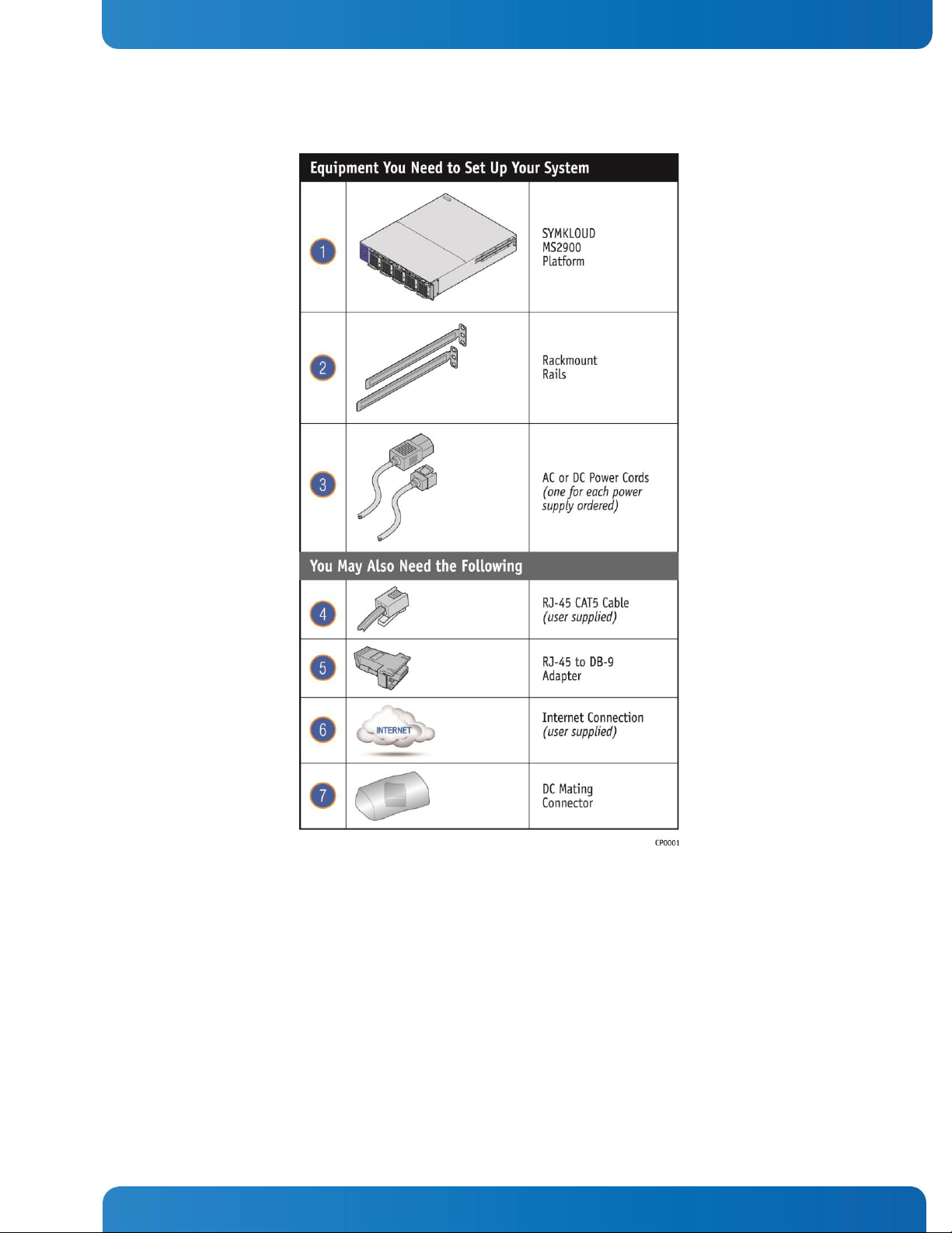
Figure 1: Components for Initial Set-Up ............................................................................................... 7
Figure 2: Attaching the Slide Rails to the Chassis .................................................................................. 9
Figure 3: Connecting the AC Power Cord and Grounding Cable ................................................................ 10
Figure 4: Connecting the DC Power Cord and Grounding Cable ................................................................ 10
Figure 5: Grounding Lug Positions ...................................................................................................... 11
Figure 6: MS2900 Front I/O Connections ............................................................................................. 12
Figure 7: RJ-45 to DB-9 Console Adapter ............................................................................................. 13
Figure 8: MS2900 Rear I/O Connections ............................................................................................... 13
Figure 9: MS2900 Front and Rear LEDs ................................................................................................. 16
Figure 10: IP Addresses ..................................................................................................................... 18
Figure 11: Hub and Processor Node Port Mapping ................................................................................. 19
Figure 12: System Monitor Login Page ................................................................................................. 26
Figure 13: System Monitor Main Page .................................................................................................. 27
Figure 14: System Monitor Main Page (Hub Information Example) ........................................................... 28
Figure 15: System Monitor Main Page (Processor Node Information Example) ........................................... 29
Figure 16: System Monitor Main Page (Hub System Upgrade Example) ..................................................... 30
Figure 17: System Monitor Main Page (Processor Node Software Upgrade Example) .................................... 31
Figure 18: One Click Upgrade Page (Processor Nodes Example) ................................................................ 32
Figure 19: SYMbalance Settings .......................................................................................................... 33
Page 5

5
www.kontron.com
Quick Start Guide
1 Before You Get Started
Caution! The SYMKLOUD MS2900 Platform is ESD sensitive equipment. Users must observe precautions for
handling electrostatic discharge sensitive devices. Also, be sure to read the ‚Safety Instructions‛ section, in
Chapter 3 of the
1.1 About this Guide
This Quick Start Guide will assist you with getting up and running on your SYMKLOUD MS2900 Platform. The
guide addresses the following tasks:
» Setting up your system and powering it on
» Using the system management configuration features
» Starting to use the operating system
» Making sure you have the latest software and firmware versions
For more detailed information on these topics or additional features of the MS2900 platform, see all the
available documentation to select what you need on the Kontron portal at http://cbu.kontron.ca/
SYMKLOUD MS2900 Platform User’s Guide
before you handle the equipment.
NOTE: To ensure you have the latest information, always check the publication dates and version numbers of
the documentation on the portal to see if there is anything more recent than what you are working from.
Page 6

6
www.kontron.com
Quick Start Guide
1.2 Equipment You Need to Set Up Your System
Figure 1 shows what you will need to get started. For instructions on how to install these components, see
Chapter 2, ‛Getting Started‛.
Depending on what you ordered for your new SYMKLOUD MS2900 system, you may have various cables,
accessories, or spare components with your shipment. For purposes of accomplishing the tasks described in
this guide, which is aimed at getting you up and running, you only need the following items from the box:
» The MS2900 system with any protective plastic or Styrofoam packaging removed
» The two rails that attach to the system chassis so it can be mounted in a cabinet/rack
» The RJ-45 to DB-9 adapter for use with a console connection
You may also need to supply the following equipment:
» Standard RJ-45 CAT5 cable (or better)
» An Internet connection
» The power cord(s) for your system: AC or DC, depending on what you ordered and if you have one
power supply unit (default) or an optional redundant power supply also
NOTE: The DC power supply ships with a mating connector that you will need to attach to the rear panel
before you power up the platform.
Page 7
7
www.kontron.com
Quick Start Guide
Figure 1: Components for Initial Set-Up
Page 8

8
www.kontron.com
Quick Start Guide
2 Getting Started
This chapter covers how to set up the MS2900 platform for installation in a cabinet/rack and how to connect
the cables.
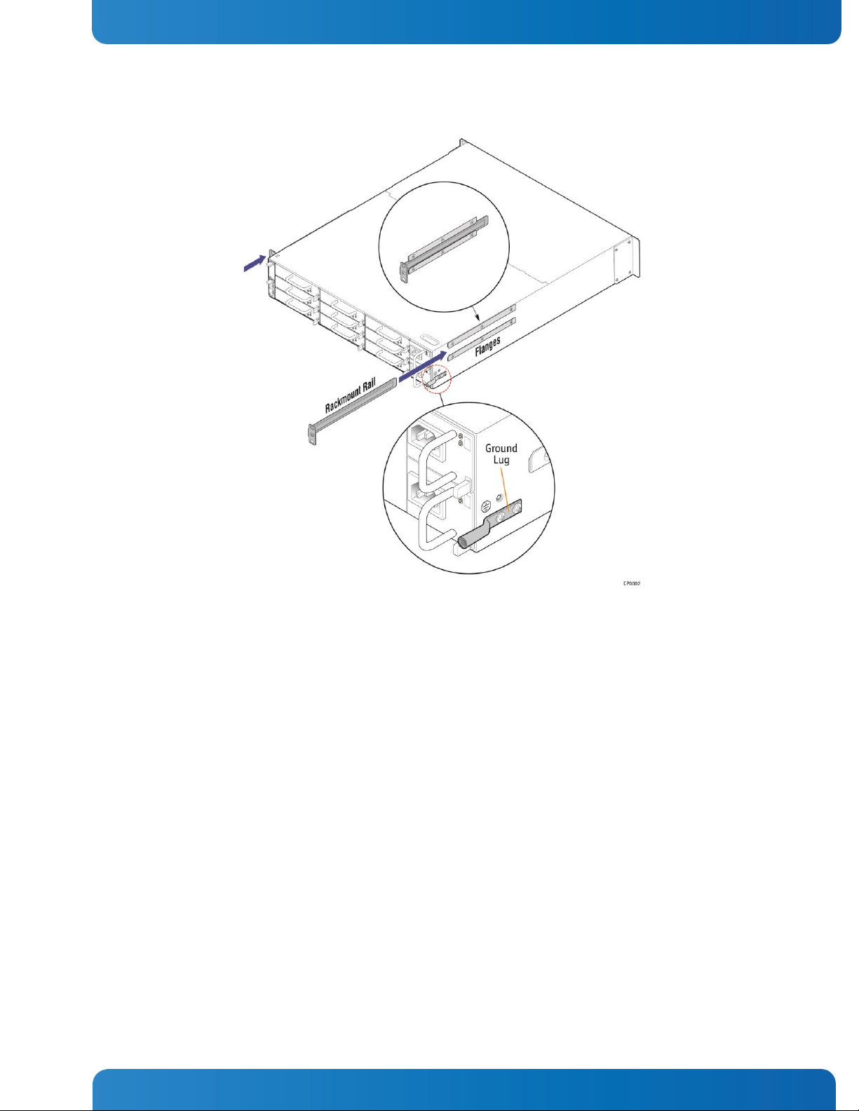
2.1 Preparing the System for Cabinet/Rack Installation
The MS2900 platform comes with both front and rear mounting attachments. The front of the chassis has
brackets attached on each side for fastening the system in a cabinet/rack. The system also comes with two
slide rails to enable mounting at the rear of the cabinet/rack.
NOTE: Because the heaviest components in the chassis, i.e., the processor nodes and power supplies are in
the rear, using the slide rails and L-brackets for rear mounting is strongly recommended. This method will
provide the most stable and secure cabinet/rack installation.
The system has rear mounting flanges for the rails already in place on both sides of the chassis. No screws are
needed; just slide the rails between the flanges with the L-bracket facing the rear of the chassis. See Figure
2.
Depending on the width of the cabinet or rack you are using, the grounding lug on the left rear side of the
chassis may make this a tight fit. If the chassis doesn’t slide in easily, you may have to tilt or wiggle the
chassis to get it into the rack. If that doesn’t work, you can remove the grounding lug by unscrewing the two
fasteners and once you have the chassis in place, re-attaching the lug from the rear of the cabinet/rack. See
Figure 2.
Page 9
9
www.kontron.com
Quick Start Guide
Figure 2: Attaching the Slide Rails to the Chassis
2.2 Connecting Power Cords
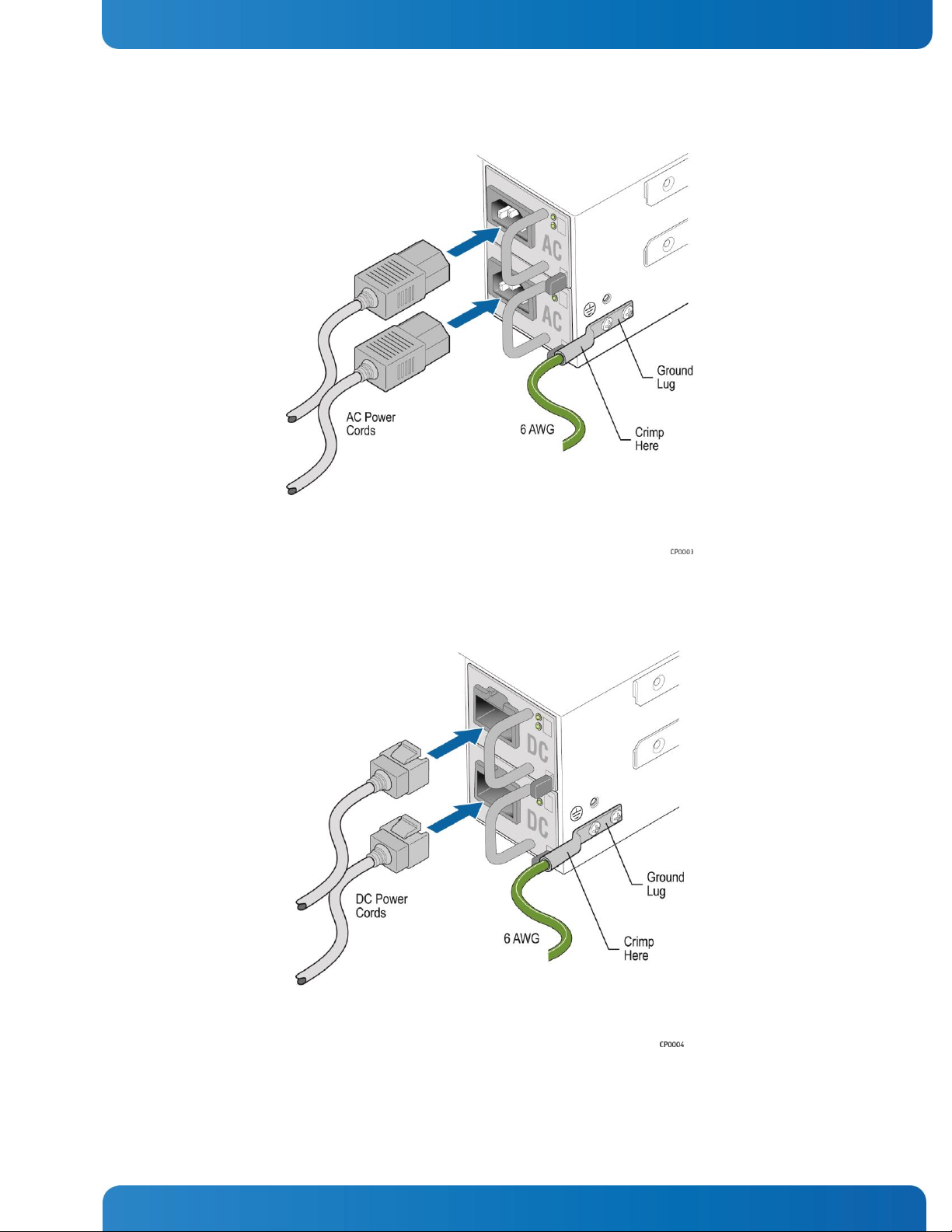
NOTE: When using a rack, wait to install the power cord(s) until after the system is in the rack.
Power cords are connected to the MS2900 platform as shown in Figure 3 and Figure 4 . MS2900 systems with
DC power supplies ship with a plastic bag containing the parts for assembling the proper connector. Printed
instructions for how to do this are also included in the bag.
Page 10
10
www.kontron.com
Quick Start Guide
Figure 3: Connecting the AC Power Cord and Grounding Cable
Figure 4: Connecting the DC Power Cord and Grounding Cable
Page 11
11
www.kontron.com
Quick Start Guide
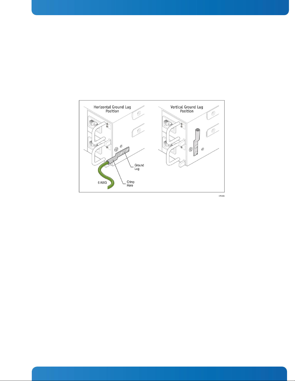
In addition to plugging in the power cord, you must also attach the grounding wire on the connector to the
grounding lug on the chassis lower right side (from the back) for proper chassis enclosure safety grounding.
The grounding lug can be positioned sideways, parallel with the chassis side, or turned up, facing toward the
top of the chassis, as shown in Figure 5.
Figure 5: Grounding Lug Positions
2.3 Connecting I/O Cables
The MS2900 platform provides I/O connections from both the front and rear of the chassis. There are two
10GbE uplink ports, two 10GbE stacking uplink ports, and eight 1GbE RJ-45 LAN ports (four for each
switch/ShMC hub,
console port and a management RJ-45 port.
front access only
) in the system. For each hub there is also front panel access for an RJ-45
Page 12

12
www.kontron.com
Quick Start Guide
I/O Port
Description
1
Management 1GbE RJ-45 port (Switch/ShMC 1)
(Marked ‘’MNGT’’ on the Hub 1 faceplate)
2
Console RJ-45 port (Switch/ShMC 1)
3
10GbE SFP+ stacking port (Switch/ShMC 1)
(Marked ‘’1’’ on the Hub 1 faceplate)
4
10GbE SFP+ uplink port (Switch/ShMC 1)
(Marked ‘’2’’ on the Hub 1 faceplate)
5
Quad 1GbE RJ-45 ports (Switch/ShMC 1)
(Marked ‘’3’’, ‘’4’’, ‘’5’’ and ‘’6’’ on the Hub 1 faceplate)
6
Management 1GbE RJ-45 port (Switch/ShMC 2)
(Marked ‘’MNGT’’ on the Hub 2 faceplate)
7
Console RJ-45 port (Switch/ShMC 2)
8
10GbE SFP+ stacking port (Switch/ShMC 2)
(Marked ‘’1’’ on the Hub 2 faceplate)
9
10GbE SFP+ uplink port (Switch/ShMC 2)
(Marked ‘’2’’ on the Hub 2 faceplate)
10
Quad 1GbE RJ-45 ports (Switch/ShMC 2)
(Marked ‘’3’’, ‘’4’’, ‘’5’’ and ‘’6’’ on the Hub 2 faceplate)
Figure 6: MS2900 Front I/O Connections
Page 13

13
www.kontron.com
Quick Start Guide
For information about port mapping for the 10GbE and 1GbE connections, see Figure 11 in the ‚Configuring
Switches subsection under Section 4.1.1.
The MS2900 platform ships with an RJ-45 to DB-9 adapter included in the box. Connect this adapter to the
console end of your RJ-45 cable when you connect to the console port on the front panel of either hub
faceplate (Figure 6, ‚2‛ or ‚7‛).
Figure 7: RJ-45 to DB-9 Console Adapter
Figure 8 shows the location of the two 10GbE uplink ports and two 10GbE stacking ports (one of each for
each switch/ShMC hub).
Figure 8: MS2900 Rear I/O Connections
Page 14

14
www.kontron.com
Quick Start Guide
3 First Power-Up
This chapter covers what to expect when you boot up the system for the first time. Both normal and
unexpected conditions are described and troubleshooting tips are provided.
At initial power up, you do not need to press the power button. You only need to connect the power cord(s).
Once the system is on, pressing the power button triggers a clean shutdown or standby event on any active
nodes. The inactive shelf manager can also go to standby state or off. Pressing the power button for four
seconds immediately turns off all nodes.
Using the System Monitor Web Interface (SMWI) is the fastest way to bring up your system and configure the
network, load balancing (SYMbalance), and payload. For information about using the SMWI for these
configuration tasks, see Section 6.1, ‚System Monitor‛. For information about using other access methods,
see the
SYMKLOUD MS2900 Platform User’s Guide
.
3.1 Normal Behavior
The normal behavior after initial power up is defined as follows:
1. As soon as power is applied to the unit, the fans start speeding up.
2. All processor nodes will have their ID LEDs ‘ON’ with no payload (blue) and the front panel chassis ID
LED will also be ‘ON’.
3. After a few seconds, the hub(s) starts booting up:
- Hub 1 (left side) power LED goes ‘ON’ (green) to indicate the active ShMC.
- Hub 2 (right side), if installed, power LED is blinking green to indicate the backup ShMC.
4. The fan manager on the ShMC starts controlling the fans, slowing down their speed.
5. The processor nodes start booting up:
- Their ID LED changes from ‘ON’ with no payload (blue) to ‘OFF’, which means the node is on or on
standby and payload is present.
- The power LED goes from ‘OFF’ to ‘ON’ and payload present (green).
6. Other platform components finish booting up and you can now interact with the switches, shelf
managers, SYMbalance, and processor nodes.
3.2 Unexpected Behavior (Troubleshooting)
The following conditions, while unlikely, could possibly occur:
» A processor node ID LED remains on.
» A hub ID LED remains on.
» A fan LED is on (amber), which indicates a fan fault.
Page 15

15
www.kontron.com
Quick Start Guide
» Fans speed up to the maximum level and stay there. The fan manager on the ShMC does not slow
them down.
The manufacturing site checks for all of these conditions when the unit is built and ensures they do not occur
when the MS2900 platform is shipped. If you experience any of these problems or other unexpected
conditions, please consult the
the Kontron portal at http://cbu.kontron.ca/ for information about how to resolve the issue and continue
working with your system.
NOTE: If a power failure occurs, the system automatically reboots when power is restored and goes through
the normal steps as described in Section 3.1.
Kontron SYMKLOUD MS2900 Platform Installation and Maintenance Guide
on
3.3 Health and Status Indicators
This section covers all of the LEDs on the MS2900 platform: on the hub faceplates, the front panel, uplink
connections, the processor nodes, and the power supplies. Figure 9 shows the LED locations.
Page 16

16
www.kontron.com
Quick Start Guide
Figure 9: MS2900 Front and Rear LEDs
Page 17

17
www.kontron.com
Quick Start Guide
4 Basic Configuration
This chapter covers the following topics:
» Configuring your system network
» Configuring your system nodes
» Configuring your (optional) SYMbalance load balancing
There are a few different ways to do the basic system configuration. The subsections in this chapter cover the
various methods.
As briefly explained in chapter 3, the System Monitor Web Interface (SMWI) can help you get through the
initial configuration as well as upgrades by displaying a series of screens to take you through the
configuration process.
Tasks/topics you can do with the SMWI are:
» Checking system status
» Upgrading software
» Linking switches and SYMbalance modules
Once you have logged in, the SMWI creates a system inventory page with all node configuration information.
For more information about SMWI features, see Section ‚System Monitor‛.
4.1 Configuring Your System Network
You need to configure your MS2900 platform for your specific network environment. There are two different
ways to access the system components and tailor your networking:
» Using management networking, as shown in Section 4.1.1
» Using a serial console, as shown in Section 4.1.2
Using Management Networking 4.1.1
Each device on the MS2900 platform comes pre-configured with an IP address. The SMWI displays a list of
each device and its IP address. For more information about the SMWI features, see Section ‚System Monitor.
Figure 10 shows the IP addresses for the ShMC/switch hubs and the processor nodes.
Page 18

18
www.kontron.com
Quick Start Guide
Figure 10: IP Addresses
When configuring the MS2900 system, set up your equipment (e.g., a laptop) to use the same subnet as the
MS2900 platform. Use the 1GbE RJ-45 management port (leftmost, marked ‚MNGT‛ on the hub faceplate) on
the active hub to connect your equipment to the MS2900 platform. This is a 10/100/1000 Mbit connection.
Configuring Processor Nodes
Use KVM through the SMWI (see Section 6.1.1) or serial access (see Section 4.1.2) to connect to the
processor nodes.
Once the processor nodes are configured, you can then configure the fabric GbE interfaces to meet your
specific needs.
Configuring Switches
To configure a switch, type in the pre-configured master switch IP address 192.168.10x.10 (Figure 10,
footnote 2) in your web browser to access the switch SMBStaX™ GUI.
Figure 11 shows the port mapping for the switch.
Page 19

19
www.kontron.com
Quick Start Guide
Figure 11: Hub and Processor Node Port Mapping
On both Hub 1 and Hub 2, port 2, labeled ’’2’’ on the hub faceplate, is the 10GbE uplink port. This is the port
that connects to the switch port #2.
On both Hub 1 and Hub 2, port 1, labeled ’’1’’ on the hub faceplate, is for stacking multiple SYMKLOUD
MS2900 systems. This port connects to switch port #1.
If the MS2900 system is equipped with optional rear uplink modules:
- Stacking is performed using port 1 of each uplink module (marked on the faceplate), which is routed
to switch port #1.
- A 10GbE uplink port is available on port 2 of each uplink module (marked on the faceplate) and
routed to switch port #2.
NOTE: In the SMBStaX™ GUI, port #1 is not visible since it is used for stacking.
Chassis slots 7 and 9 have 10GbE pipes to support up to two SYMbalance modules optionally or two additional
provisioning processor nodes:
- Hub 1, port #22 (node 7 fabric 1)
- Hub 2, port #24 (node 9 fabric 2)
All other ports are 1GbE.
Page 20

20
www.kontron.com
Quick Start Guide
Using a Serial Console 4.1.2
You can access the components of your MS2900 platform by using the MSH8900 serial console multiplexer
(MUX). Follow these steps:
1. Connect a serial cable to the Hub 1 serial console port on the front of the MS2900 platform. (See ‚2‛
on Figure 6.)
Use the RJ-45 to DB-9 adapter that shipped with the system on the console end of the cable.
2. Run a VT100 terminal emulator with the following serial port communication parameters:
115200 baud
no parity
8 data bits
3. To switch the serial console across different components, press CTRL g and then the number for the
component you want to configure.
The numbers for each component are:
0: Shelf manager (ShMC)
1 to 9: processor node 1 through node 9
– (minus): switch CLI
For example, to direct the serial console to processor node 7, press CTRL g and then press 7.
Configuring Shelf Management Controllers (ShMCs)
To connect the serial console MUX to a ShMC, follow these steps:
1. Press CTRL g and then press 0 to switch the console to the ShMC.
2. Log in with the user admin password: admin.
3. In root mode, use admin again for the password and type sudo –s.
You should now get the ipmitool> prompt.
To set the IP address:
1. Type lan set 1 ipsrc dhcp
To use a static IP address:
1. Type lan set 1 ipsrc static
2. Type lan set 1 ipaddr 192.168.100.X
3. Type lan set 1 defgw ipaddr 192.168.100.X
4. Type lan set 1 netmask 255.255.255.X
Page 21

21
www.kontron.com
Quick Start Guide
Configuring Processor Nodes through the ShMC
1. Switch the serial console MUX to address the ShMC, as follows:
Press CTRL g and then press 0 to switch the console to the ShMC.
2. Node management controller IP setup is done using the ShMC CLI.
By default, all commands are targeted for the active ShMC (where you are connected).
For the command to target a node, you must modify the target by using
set targetaddr <address>, where <address> is the address of the desired node.
a. Select the address from the following list:
ShMC 1 = 0x20 (active)
ShMC 2 = 0x10 (standby)
Node 1 = 0x82**
Node 2 = 0x84
Node 3 = 0x86
Node 4 = 0x88
Node 5 = 0x8a
Node 6 = 0x8c
Node 7 = 0x8e
Node 8 = 0x90
Node 9 = 0x92
b. This command returns:
Set remote IPMB address to <address>
c. As an option to ensure the correct node is used, you can print the node FRU and check the
‚Board Serial‛ field. Type fru
d. To target back to the active ShMC, use
set targetaddr 0x20.
Now that your target address has been changed, to set the IP address using DHCP:
1. Type lan set 1 ipsrc dhcp
2. NOTE: To set the DHCP IP address on all nodes quickly:
For i below type in 82 84 86 88 8a 8c 8e 90 92
set targetaddr 0x$i; lan set 1 ipsrc dhcp; done
To use a static IP address:
1. Type lan set 1 ipsrc static
2. Type lan set 1 ipaddr 192.168.100.X
3. Type lan set 1 defgw ipaddr 192.168.100.X
4. Type lan set 1 netmask 255.255.255.X
Page 22

22
www.kontron.com
Quick Start Guide
Configuring Switches
To change the serial console MUX to address a switch, follow these steps:
1. Press CTRL g and then press – (minus)
Login as admin with no password
2. Go to IP mode. Type /ip
3. Set IP DHCP. Type dhcp 4093 enable
4. Set static IP address.
Type address 4093 192.168.100.X
Type route add 192.168.100.0/24 192.168.100.X
Type route add 0.0.0.0/0 192.168.100.X
NOTE: /24 = 255.255.255.0, /16 = 255.255.0.0, /8 = 255.0.0.0
Configuring Your System SYMbalance Node(s)
SYMbalance nodes are optional. Depending on whether you have one or two hub modules installed, you will
configure a SYMbalance node in slot 7 for Hub 1 and optionally in slot 9 if you are using Hub 2 and want to
have two SYMbalance nodes.
NOTE: One node or none is okay even with two hub modules.
To switch to a SYMbalance node, change the serial console MUX to 7 as follows, or 9:
1. Press CTRL g and then press 7
2. Change login to touch /touch
(DHCP configuration is not supported)
To configure the SYMbalance node in slot 7 (Hub 1):
1. Connect an RJ-45 serial cable to the console RJ-45 port on Hub 1. (See Figure 6, ‚2‛ )
2. Using this cable, connect a serial terminal or a workstation running terminal emulator software.
The terminal must be set to:
115200 baud
8 data bits
no parity
one stop-bit
VT100 emulation
and ignore hang-ups (if supported).
3. Log in using the default administrative user name, touch, and default password, touch.
The CLI prompt, egcli >, is displayed.
Page 23

23
www.kontron.com
Quick Start Guide
4. To change the password for the touch login, enter the command
eqcli > user touch password
and follow the prompts.
To use a static IP address:
1. Type vlan management subnet sn01_Management ip 192.168.100.X/24
default_route 192.168.100.X.
NOTE: /24 = 255.255.255.0, /16 = 255.255.0.0, /8 = 255.0.0.0.
Page 24

24
www.kontron.com
Quick Start Guide
5 Running an Operating System
The SYMKLOUD MS2900 platform can be shipped with or without a pre-installed operating system.
If your system was ordered with a pre-installed OS on the processor nodes, you will have received instructions
and information that is supplementary to this Guide.
If your system was ordered without a pre-installed OS on the processor nodes, you will need to install a
supported OS now.
Accessing Processor Nodes
The system payload varies depending on the application. Examples using generic access points and OS
installation tips are presented below:
For MSP8000/MSP8001/MSP8020 platforms, use KVM/VM or the serial port to access the node.
5.1 First Boot-Up
If an operating system was pre-installed on your MS2900 platform, the processing nodes will have the OS
booted up as part of the powering up process.
5.2 Advanced: OS Installation
Kontron provides an example of a typical OS installation on a processor node in an application note on
http://cbu.kontron.ca/. This application note is a ‚how to‛ example that shows the procedure for installing
CentOS 6.3 on local storage of a node. You can use this application note for general guidance on how to
install your chosen OS. However, there will be some customization steps needed to get your OS installed
according to your specific requirements.
NOTE: Check http://cbu.kontron.ca/ for the latest available documentation.
5.3 BIOS Configuration
The BIOS configuration described below refers to x86 nodes and is Unified Extensible Firmware Interface
(UEFI) compatible.
To enter the BIOS:
1. Power on or reboot the node or system.
2. During POST (when getting the first outputs on the screen),
press the <F2> or <Del> key to enter the BIOS setup.
Page 25

25
www.kontron.com
Quick Start Guide
The Setup default values are the optimum performance settings for all devices and system features. However,
you can change some of the settings, particularly the device boot order, to better fit your needs.
For MSP8000/MSP8001 nodes, the default boot order is:
» Remote devices using Virtual Media support
» Local SATA or an on-board eUSB drive (if available)
» Internet network connection (PXE)
For MSP8020 nodes, the default boot order is:
» On-board SATA SSD
» Internet network connection (PXE)
Page 26

26
www.kontron.com
Quick Start Guide
6 Making Sure Your System is Up-to-Date
This chapter presents the provisions Kontron has for helping you ensure your SYMKLOUD MS2900 platform is
up-to-date with the latest software and firmware.
6.1 System Monitor
System Monitor is a Kontron software product that manages configuration tasks for the SYMKLOUD MS2900
platform. The System Monitor Web Interface (SMWI) is the user interface for this underlying software. You use
the SMWI for both monitoring and updating your MS2900 platform. The recommended way to manage your
system is to make a serial console connection. See Figure 6, ‚MS2900 Front I/O Connections‛ for the location
of the serial console port for each hub on the front panel of the MS2900 platform. An RJ-45 to DB-9 adapter
for use with your console is provided with the system.
To log in to the System Monitor software, use the initial default user id and password settings:
» User ID = admin
» Password = admin
The Kontron System Monitor provides data on your current system so you can check version levels and
capacities. To get started using the System Monitor interface from your console connection, log in using your
browser (preferably Firefox or Chrome), as follow:
1. Enter the active shelf manager IP address to see the System Monitor Login page shown in Figure 12.
Figure 12: System Monitor Login Page
Page 27

27
www.kontron.com
Quick Start Guide
Section
Function
System status bar
Overall system status/health and fan speed for all five fans
Left side panel
Menu of key chassis components: hubs and processor nodes
Right side panel
Tab 1: Information for the component selected in the menu
Tab 2: Software update for the selected component.
2. Type the following values into the form:
USERNAME: admin
PASSWORD: admin
and click Sign in to access the SYMKLOUD System Monitor.
Main Page Overview 6.1.1
Figure 13 shows the layout of the System Monitor main page. This is the key user interface.
Figure 13: System Monitor Main Page
The System Monitor main page as shown in Figure 13 has three main sections:
Page 28

28
www.kontron.com
Quick Start Guide
The system status bar showing the overall system status and the fan speeds is displayed at the top of all the
SMWI pages.
The left side panel is the chassis components menu where you can select
1. Hubnodes: either Hub 1 or Hub 2
2. Nodes: any of the nine processor nodes
The right side panel has two tabs:
1. Information: Displays the health/status and IP address of the key components of the hub or processor
node selected in the left side panel menu.
2. Software Upgrade: Displays the current software levels and allows you to select software you want to
upload for an upgrade.
Right Side Panel - Information Views 6.1.2
Figure 14 shows an example of the System Monitor main page with Hub 1 selected in the menu and the
Information tab selected in the right side panel.
Figure 14: System Monitor Main Page (Hub Information Example)
Figure 15 shows an example of the System Monitor main page with Processor Node 2 selected in the menu
and the Information tab selected in the right side panel.
Page 29

29
www.kontron.com
Quick Start Guide
Figure 15: System Monitor Main Page (Processor Node Information Example)
When processor nodes are selected from the left side menu, the Information tab has a Remote Access
function after the IP address and health information, as follows:
Page 30

30
www.kontron.com
Quick Start Guide
Right Side Panel - Software Upgrade Views 6.1.3
Figure 16 shows an example of the System Monitor main page with Hub 1 selected in the menu and the
Software Upgrade tab selected in the right side panel. .
Figure 16: System Monitor Main Page (Hub System Upgrade Example)
In this example, the current BMC and FPGA software versions are displayed and either of these can be
selected for uploading and an upgrade.
Figure 17 shows an example of the System Monitor main page with Processor Node 2 selected in the menu
and the Software Upgrade tab selected in the right side panel.
Page 31

31
www.kontron.com
Quick Start Guide
Figure 17: System Monitor Main Page (Processor Node Software Upgrade Example)
In this example, for processor node 2, the current HPM versions of the BMC, FPGA, and BIOS are displayed
and any of these can be selected for uploading and an upgrade.
From a system upgrade page, when you select Start Upgrade, a OneClick Upgrade page, like the following
example in Figure 18, is displayed:
Page 32

32
www.kontron.com
Quick Start Guide
Figure 18: One Click Upgrade Page (Processor Nodes Example)
Right Panel SYMbalance View (Nodes 7 and 9)
6.1.4
Follow these steps to get the IP address for a SYMbalance node:
1. To get a SYMbalance node IP address, connect to the active shelf manager serial port.
2. Login with admin:admin
3. Type command:
# set localaddr 0x20
4. To get the address for slot 7:
Type # set targetaddr 0x8E
5. To get the address for slot 9:
Type # set targetaddr 0x92
6. Type # lan print 1
Figure 19 shows the information displayed when slot 7 or slot 9 is selected for use as a SYMbalance node.
Page 33

33
www.kontron.com
Quick Start Guide
Figure 19: SYMbalance Settings
Page 34

34
www.kontron.com
Quick Start Guide
7 Additional Resources
This chapter provides information about where additional SYMKLOUD MS2900 Platform product information
can be found and how to contact a Kontron technical support engineer.
7.1 MS2900 Platform Documentation
For more detailed information about this system, see all the most recently published documents on the
Kontron portal at http://cbu.kontron.ca/. Besides manuals and marketing literature, you may also find
Product Change Notifications (PCNs) that are published if there are system changes after the release date.
7.2 Contact Information
Technical Support 7.2.1
Technicians and engineers from Kontron and/or its subsidiaries are available for technical support. We are
committed to making our product easy to use and will help you use our products in your systems.
Please consult our website at http://www.kontron.com/support for the latest product documentation,
utilities, drivers and support contacts. In any case you can always contact your board supplier for technical
support.
Page 35

35
www.kontron.com
Quick Start Guide
8 Trademarks and Copyright
8.1 Copyright Notice
Copyright © 2013 Kontron America Inc.
All rights reserved. No part of this document may be reproduced, transmitted, transcribed, stored in a
retrieval system, or translated into any language or computer language, in any form or by any means
(electronic, mechanical, photocopying, recording, or otherwise), without the express written permission from
Kontron.
8.2 Quality Standards
Kontron is certified to ISO 9000 Quality Standards.
Page 36

36
www.kontron.com
Quick Start Guide
Europe, Middle East & Africa
Oskar-von-Miller-Str. 1
85386 Eching/Munich
Germany
Tel.: +49 (0)8165/ 77 777
Fax: +49 (0)8165/ 77 219
info@kontron.com
North America
14118 Stowe Drive
Poway, CA 92064-7147
USA
Tel.: +1 888 294 4558
Fax: +1 858 677 0898
info@us.kontron.com
Asia Pacific
17 Building Block #1, ABP.
188 Southern West 4th Ring
Beijing 100070, P.R.China
Tel.: + 86 10 63751188
Fax: + 86 10 83682438
info@kontron.cn
Corporate Offices
 Loading...