

Page 1
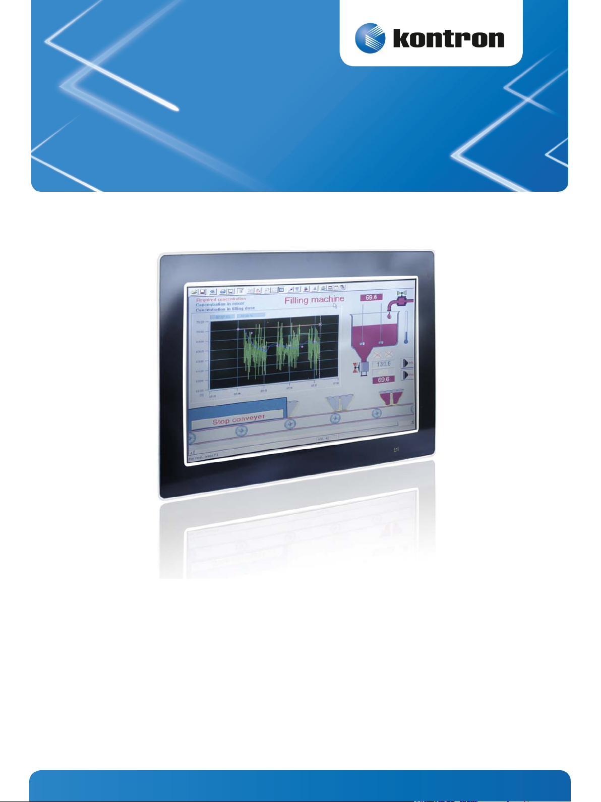
Micro Client 3 104/121/150/170
» User Guide «
Micro Client 3W 156
User’s Guide (Version 1.0)
1055-8487
www.kontron.com
Page 2

This page is intentionally left blank.
www.kontron.com
Page 3

1. Table of Contents Micro Client 3 – User’s Guide (Version 1.0)
1. Table of Contents
1. Table of Contents ................................................................................................................................... 1
1.1. Table of Figures .................................................................................................................................... 3
1.2. Tables ................................................................................................................................................ 4
2. Introduction ......................................................................................................................................... 5
2.1. Symbols used in this User’s Guide ............................................................................................................. 6
3. Important Instructions ........................................................................................................................... 7
3.1. Note on the Warranty ............................................................................................................................ 7
3.2. Exclusion of Accident Liability Obligation ................................................................................................... 7
3.3. Liability Limitation / Exemption from the Warranty Obligation ........................................................................ 7
4. General Safety Instructions for IT Equipment .............................................................................................. 8
4.1. Electrostatic Discharge (ESD) ................................................................................................................ 10
4.1.1. Grounding Methods ...................................................................................................................... 10
4.2. Hot Surface Warning ........................................................................................................................... 10
5. Electromagnetic Compatibility ............................................................................................................... 11
5.1. Electromagnetic Compatibility EU ........................................................................................................... 11
5.2. FCC Statement (USA) ........................................................................................................................... 11
5.3. EMC Compliance Canada ....................................................................................................................... 11
6. Scope of Delivery ................................................................................................................................. 12
6.1.1. Optional Parts ............................................................................................................................. 12
6.2. Type Label and Product Identification ...................................................................................................... 13
7. Product Description.............................................................................................................................. 14
7.1. Front Side View .................................................................................................................................. 17
7.1.1. USB Interface Connector on the Front Side of the MC 3 104/121/150/170 Systems ..................................... 18
7.1.2. MC 3 104/121/150/170 Systems - Front Plate Version .......................................................................... 18
7.1.3. Calibrating the Touch Screen (resistive) ............................................................................................ 19
7.1.4. Touch Screen Care and Cleaning ....................................................................................................... 21
7.1.5. MC 3W 156 System - Front Plate ....................................................................................................... 21
7.2. Bottom View ...................................................................................................................................... 22
7.2.1. Power and Grounding .................................................................................................................... 23
7.2.2. Power Button and Control Indicators ................................................................................................ 24
7.2.3. Interfaces (Rear, Bottom Side of the System) ..................................................................................... 26
7.3. Optional Interfaces ............................................................................................................................. 27
7.3.1. RS422/RS485 Serial Interface Connector/s ........................................................................................ 27
7.3.2. DIP-Switch Settings (SW1) for LPCtoCAN Adapter ................................................................................ 29
7.4. Top View ........................................................................................................................................... 31
7.4.1. CompactFlash™ Slot and SD card Slot ................................................................................................ 32
7.5. Left and Right Side View ....................................................................................................................... 33
7.6. Rear View .......................................................................................................................................... 34
7.6.1. VESA® Mounting Plate (Option) ....................................................................................................... 35
7.7. Installed SBC ..................................................................................................................................... 37
7.8. DC Power Connection ........................................................................................................................... 37
7.8.1. DC Power Connector ...................................................................................................................... 37
7.9. Accessing Internal Components ............................................................................................................. 38
7.9.1. Configuration of the RS422/RS485 Port (MC 3 104/121/150/170, MC 3W 156) ........................................... 38
www.kontron.com 1
Page 4

1. Table of Contents Micro Client 3 – User’s Guide (Version 1.0)
7.10. Getting started ................................................................................................................................. 40
7.10.1. Connecting to Power .................................................................................................................... 40
7.11. Operating System and Hardware Component Drivers .................................................................................. 41
7.12. MC 3/MC 3W System Mounting to a Subframe or Panel ................................................................................ 42
8. Maintenance and Prevention ................................................................................................................. 44
9. Technical Data .................................................................................................................................... 45
9.1. Electrical Specifications ........................................................................................................................ 48
9.1.1. Electrical Specifications for MC 3 104/121/150/170/3W 156 System ........................................................ 48
9.2. Environmental Specifications ................................................................................................................. 48
9.3. Mechanical Specifications ..................................................................................................................... 49
9.3.1. Dimensions for MC 3 104/121/150/170 and MC 3W 156 ......................................................................... 49
9.4. CE Directives and Standards ................................................................................................................... 56
10. Standard Interfaces – Pin Assignments ................................................................................................. 57
10.1.1. Power Connector ......................................................................................................................... 57
10.1.2. Serial interface COM (RS232) ......................................................................................................... 57
10.1.3. Serial Port (RS422/RS485) configured as RS422 (4-Channel Mode) ........................................................ 58
10.1.4. Serial Port (RS422/RS485) configured as RS485 (4-Wire Mode), full duplex, (Bus-Master) ........................... 58
10.1.5. Serial Port (RS422/RS485) configured as RS485 (2-Wire Mode), half duplex ............................................. 59
10.1.6. CAN Connector ........................................................................................................................... 59
10.1.7. DP Connector (DisplayPort) ........................................................................................................... 60
10.1.8. USB Port ................................................................................................................................... 60
11. Technical Support .............................................................................................................................. 61
11.1. Returning Defective Merchandise .......................................................................................................... 61
2 www.kontron.com
Page 5

1. Table of Contents Micro Client 3 – User’s Guide (Version 1.0)
1.1. Table of Figures
Fig. 1: Bottom view ................................................................................................................................... 15
Fig. 2: Right view ...................................................................................................................................... 15
Fig. 3: Frontal view ................................................................................................................................... 15
Fig. 4: Left view ........................................................................................................................................ 15
Fig. 5: Top view ........................................................................................................................................ 15
Fig. 6: Rear view ....................................................................................................................................... 15
Fig. 7: Bottom view ................................................................................................................................... 16
Fig. 8: Right view ...................................................................................................................................... 16
Fig. 9: Frontal view ................................................................................................................................... 16
Fig. 10: Left view ...................................................................................................................................... 16
Fig. 11: Top view....................................................................................................................................... 16
Fig. 12: Rear view ..................................................................................................................................... 16
Fig. 13: Frontal view of the MC 3 104/121/150/170 system (shown as a 10.4" display) ............................................. 17
Fig. 14: Frontal view of the MC 3W 156 system ................................................................................................. 17
Fig. 15: Hampshire TSHARC™ Control Panel .................................................................................................... 19
Fig. 16: Select “Tools” tab ........................................................................................................................... 20
Fig. 17: Select “4 Points Calibration” ............................................................................................................. 20
Fig. 18: Touch the calibration targets and complete the calibration ...................................................................... 20
Fig. 19: Bottom view of the MC 3 104 ............................................................................................................. 22
Fig. 20: Bottom view of the MC 3 156 ............................................................................................................. 22
Fig. 21: Detail of the DC Power connector shown without Phoenix terminal ............................................................ 23
Fig. 22: Controls of the MC 3 system (bottom rear side) ..................................................................................... 24
Fig. 23: Color code for current system power state ............................................................................................ 24
Fig. 24: Color of the storage drive activity LED, depending on the system configuration ............................................ 25
Fig. 25: Detail with interfaces for MC 3 104 system ........................................................................................... 26
Fig. 26: Detail with interfaces for MC 3 121/150/170 and MC 3W 156 systems ......................................................... 26
Fig. 27: Onboard DIP-Switch (SW1) with DP1 up to DP8 for RS422/RS485 serial communication settings ...................... 27
Fig. 28: DIP-Switch of the LPCtoCAN Adapter ................................................................................................... 29
Fig. 29: Color legend used in the Table 4, Table 5 and Table 6: ............................................................................. 29
Fig. 30: Top side of the system (shown as MC 3W 156, with CF/SD card slot cover attached) ........................................ 31
Fig. 31: Top side of the system (shown as MC 3 104, with CF/SD card slot cover removed) .......................................... 31
Fig. 32: Right side shown as MC 3W 156 system ................................................................................................ 33
Fig. 33: Left side shown as MC 3W 156 system .................................................................................................. 33
Fig. 34: Right side of the MC 3 104 system ...................................................................................................... 33
Fig. 35: Left side of the MC 3 104 system ........................................................................................................ 33
www.kontron.com 3
Page 6

1. Table of Contents Micro Client 3 – User’s Guide (Version 1.0)
Fig. 36: Rear side of the system (shown as a MC 3W 156 system) .......................................................................... 34
Fig. 37: Rear side of the system (shown as a MC 3 104 system) ............................................................................ 34
Fig. 38: Rear and bottom view of the mounting plate VESA® 100 compliant for MC 3 104 ........................................... 35
Fig. 39: Rear and bottom view of the mounting plate VESA® 75/100 for MC 3W 156 .................................................. 36
Fig. 40: Phoenix power plug terminal with “plus” and “minus” marking (MC 3 104/156/170) ..................................... 37
Fig. 41: DIP1-DIP8 switches (shown with factorry settings) ................................................................................ 39
Fig. 42: Connecting to DC power source ......................................................................................................... 40
Fig. 43: Detail with mounting clamps and a subframe (shown with a MC 3 104 system) ............................................. 42
Fig. 44: Detail with mounting clamps and a subframe (shown with a MC 3W 156 system) ........................................... 42
Fig. 45: Frontal view of the MC 3 104 system ................................................................................................... 49
Fig. 46: Frontal view of the MC 3 121 system ................................................................................................... 50
Fig. 47: Frontal view of the MC 3 150 system ................................................................................................... 50
Fig. 48: Frontal view of the MC 3 170 system ................................................................................................... 51
Fig. 49: Frontal view of the MC 3W 156 system ................................................................................................. 52
1.2. Tables
Table 1: DIP1, DIP2 and DIP3 settings for serial communication type.................................................................... 27
Table 2: DIP4 setting in order to activate or deactivate the termination resistor ...................................................... 28
Table 3: DIP5, DIP6, DIP7 and DIP8 settings in order to set the needed timeout and min. baud rate ............................. 28
Table 4: SJA-Base Address Settings .............................................................................................................. 29
Table 5: SJA-Interrupt Settings ................................................................................................................... 29
Table 6: NVRAM-Operation Mode Settings ...................................................................................................... 30
Table 7: Requirements for the MC 3 104/121/150/170 and MC 3W 156 mounting into a subframe/panel ...................... 43
4 www.kontron.com
Page 7

2. Introduction Micro Client 3 – User’s Guide (Version 1.0)
2. Introduction
Kontron Europe would like to point out that the information contained in this manual may be subject to technical
alteration, particularly as a result of the constant upgrading of Kontron Europe products. The attached documentation
does not entail any guarantee on the part of Kontron Europe with respect to technical processes described in the manual or
any product characteristics set out in the manual. Kontron Europe does not accept any liability for any printing errors or
other inaccuracies in the manual unless it can be proven that Kontron Europe is aware of such errors or inaccuracies or that
Kontron Europe is unaware of these as a result of gross negligence and Kontron Europe has failed to eliminate these errors
or inaccuracies for this reason. Kontron Europe expressly informs the user that this manual only contains a general
description of technical processes and instructions which may not be applicable in every individual case. In cases of doubt,
please contact Kontron Europe.
This manual is protected by copyright. All rights are reserved by Kontron Europe. Copies of all or part of this manual or
translations into a different language may only be made with the prior written consent of Kontron Europe. Kontron Europe
points out that the information contained in this manual is constantly being updated in line with the technical alterations
and improvements made by Kontron Europe to the products and thus this manual only reflects the technical status of the
products by Kontron Europe at the time of printing.
© 2013 by Kontron Europe GmbH
Printing and duplication, even of sections, is only permissible with the express approval of
Kontron Europe GmbH
Sudetenstr. 7
87600 Kaufbeuren
Germany
www.kontron.com 5
Page 8
2. Introduction Micro Client 3 – User’s Guide (Version 1.0)
2.1. Symbols used in this User’s Guide
Symbol Meaning
This symbol indicates the danger of injury to the user or the risk of damage to the product if the
corresponding warning notices are not observed.
This symbol indicates a hot surface that should not be touched without taking care.
This symbol indicates that the product or parts thereof may be damaged if the corresponding warning
notices are not observed.
This symbol indicates general information about the product and the user’s guide.
This symbol indicates detail information about the specific product configuration.
This symbol precedes helpful hints and tips for daily use.
6 www.kontron.com
Page 9

3. Important Instructions Micro Client 3 – User’s Guide (Version 1.0)
3. Important Instructions
This chapter contains instructions which must be observed when using your Micro Client 3 system. The manufacturer’s
instructions provide useful information on your device.
3.1. Note on the Warranty
Due to their limited service life, parts which by their nature are subject to a particularly high degree of wear (wearing
parts) are excluded from the warranty beyond that provided by law. This applies to batteries, to the display backlighting,
for example.
3.2. Exclusion of Accident Liability Obligation
Kontron Europe shall be exempted from the statutory accident liability obligation if the user fails to observe the included
document: “General Safety Instructions for IT Equipment” the hints in this manual or eventually the warning signs label on
the device.
3.3. Liability Limitation / Exemption from the Warranty Obligation
In the event of damage to the device caused by failure to observe the included document “General Safety Instructions for IT
Equipment”, the hints in this manual or eventually the warning signs label on the device, Kontron Europe shall not be
required to honor the warranty even during the warranty period and shall be exempted from the statutory accident liability
obligation.
www.kontron.com 7
Page 10

4. General Safety Instructions for IT Equipment Micro Client 3 – User’s Guide (Version 1.0)
4. General Safety Instructions for IT Equipment
Please read this section carefully and observe the instructions for your own safety and correct use of the device.
The chapter also contains information on approval and interference suppression of your device.
Observe the warnings and instructions on the device and in the manual.
The MC 3 system has been built and tested by Kontron Europe in accordance to
IEC/EN/UL/CSA 60950-1 and left the company in a perfectly safe condition.
In order to maintain this condition and ensure safe operation, the user must observe the instructions and warnings
contained in this manual.
The device must be used in accordance with the instructions for use.
The electrical installations in the room must correspond to the requirements of the local (country-specific) regulations.
Take care that there are no cables, particularly power cables, in areas where persons can trip over them.
Do not use a power cable in sockets shared by a number of other power consumers. Do not use an extension cable.
Only use the power cord supplied. Don’t use injured or damaged power cords.
For DC power connection:
The DC power source should be able to be switched off and on via an isolating switch.
The unit is only completely disconnected from the DC main power source, when the DC power cord is disconnected
either from the power source or the unit. Therefore, the DC power cord and its connectors must always remain easily
accessible.
For AC power connection via external AC/DC adapter:
The main power cable of the external AC/DC adapter serves as disconnecting device. For this reason the outlet of the AC
power source must be located near to the device and be easily accessible.
Do not place the device in direct sunlight, near heat sources or in a damp place. Make sure the device has adequate
ventilation.
Only devices and components which fulfill the requirements of an SELV circuit (safety extra low voltage) in accordance
with EN60950 may be connected to the interfaces of the system.
All plugs on the connection cables must be screwed or locked to the housing.
The MC 3 system is designed to be used in vertical position with the interfaces downwards.
The device generates heat during operation. Make sure it is adequately ventilated. Do not cover the air intake and
exhaust openings of the device.
Repairs may only be carried out by qualified specialist personnel authorized by Kontron Europe.
Maintenance or repair on the open device may only be carried out by qualified personnel authorized by Kontron Europe
which is aware of with the associated dangers.
The MC 3 system may only be opened in accordance with the description in this user’s guide for:
• Replacing of the Lithium battery
• Configuration of the RS422/RS485 interface
• Configuration of the CAN interface.
These procedures have to be carried-out only by qualified specialist personnel.
When accessing internal components the device must be switched off and disconnected from the power source.
Only approved original accessories (optional parts) approved by Kontron Europe may be used.
8 www.kontron.com
Page 11

4. General Safety Instructions for IT Equipment Micro Client 3 – User’s Guide (Version 1.0)
The DC-input must fulfill SELV requirements of EN60950-1 standard.
The chassis of the MC 3 system must be protective earthed by establishing a large-area contact between the earth
screw (at the rear bottom side) and an appropriate grounding connection point.
It must be assumed that safe operation is no longer possible,
• if the device has visible damage or
• if the device no longer functions.
In these cases the device must be shut down and secured against unintentional operation.
www.kontron.com 9
Page 12
4. General Safety Instructions for IT Equipment Micro Client 3 – User’s Guide (Version 1.0)
4.1. Electrostatic Discharge (ESD)
A sudden discharge of electrostatic electricity can destroy static-sensitive devices or micro-circuitry. Therefore proper
packaging and grounding techniques are necessary precautions to prevent damage. Always take the following precautions:
1. Transport boards in ESD-safe containers such as boxes or bags.
2. Keep electrostatic sensitive parts in their containers until they arrive at the ESD-safe workplace.
3. Always be properly grounded when touching a sensitive board, component, or assembly.
4. Store electrostatic-sensitive boards in protective packaging or on antistatic mats.
4.1.1. Grounding Methods
The following measures help to avoid electrostatic damages to the device:
1. Cover workstations with approved antistatic material. Always wear a wrist strap connected to workplace as well as
properly grounded tools and equipment.
2. Use antistatic mats, heel straps, or air ionizers for more protection.
3. Always handle electrostatically sensitive components by their edge or by their casing.
4. Avoid contact with pins, leads, or circuitry.
5. Turn off power and input signals before inserting and removing connectors or connecting test equipment.
6. Keep work area free of non-conductive materials such as ordinary plastic assembly aids and styrofoam.
7. Use field service tools such as cutters, screwdrivers, and vacuum cleaners which are conductive.
8. Always place drives and boards PCB-assembly-side down on the foam.
4.2. Hot Surface Warning
Please observe the warning label “Hot Surface” shown in Fig. 36 and Fig. 37on the rear side of the cabinet.
The MC 3/MC3W chassis may be hot during operation and should not be touched without taking care.
The material on bottom surface of the enclosure interior where the MC 3/MC 3W is to be mounted, shall
keep at least flammability class UL 94-5VB. Don’t put flammable materials under the device.
10 www.kontron.com
Page 13

5. Electromagnetic Compatibility Micro Client 3 – User’s Guide (Version 1.0)
5. Electromagnetic Compatibility
5.1. Electromagnetic Compatibility EU
This product is in conformity with the protection requirements of EU Council Directive 2004/108/EC on the approximation
of the laws of the Member States relating to electromagnetic compatibility. If the user modifies and/or adds to the
equipment (e.g. installation of add-on cards) the prerequisites for the CE conformity declaration (safety requirements)
may no longer apply.
Generic standards - Emission standard for residential, commercial and light-industrial environments (Emission):
EN 61000-6-3
Emission of Information technology equipment – Radio disturbance characteristics – Limits and methods of measurement:
EN 55022/B
ITE - Immunity characteristics - Limits and methods of measurement: EN 55024
5.2. FCC Statement (USA)
This equipment has been tested and found to comply with the limits for a Class A digital device, pursuant to Part 15 of the
FCC Rules. These limits are designed to provide reasonable protection against harmful interference when the equipment is
operated in commercial environment. This equipment generates, uses, and can radiate radio frequency energy and, if not
installed and used in accordance with the instruction manual, may cause harmful interference to radio communications.
Operation of this equipment in residential area is likely to cause harmful interference in which case the user will be
required to correct the interference at his own expense.
5.3. EMC Compliance Canada
(English): This Class A digital apparatus complies with the Canadian ICES-003.
(French): Cet appareil numérique de la class A est conforme à la norme NMB-003 du Canada.
www.kontron.com 11
Page 14
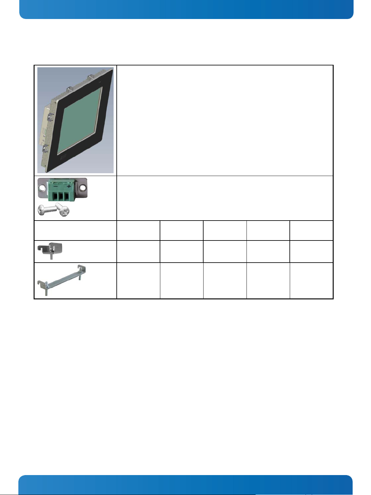
CF card (Type II)
CAN Bus Module (LPCtoCAN Adapter) (configuration via DIP switch)
6. Scope of Delivery Micro Client 3 – User’s Guide (Version 1.0)
6. Scope of Delivery
Micro Client 3 and Micro Client 3W system in the configuration ordered:
Micro Client 3 104
Micro Client 3 121
Micro Client 3 150
Micro Client 3 170
Micro Client 3W 156
Phoenix Power Plug Terminal with 2x UNC4/40 (6.4 mm) pan head screw
Mounting Clamps with Allen
Screws
6.1.1. Optional Parts
HDD (2.5" SATA internal)
SSD (2.5” SATA internal)
RS232 Module
RS422/485 Module (configuration
via DIP switch)
MC 3 104 MC 3 121 MC 3 150 MC 3 170 MC 3W 156
8x - - - 4x
- 6x 8x 8x 4x
CANopen Master Module
PROFIBUS DP Master Module
Mounting Plate VESA
MC 3 104/121/150/170 and MC 3W 156 respectively)
®
100 compliant (particular mounting plates for
12 www.kontron.com
Page 15
6. Scope of Delivery Micro Client 3 – User’s Guide (Version 1.0)
6.2. Type Label and Product Identification
System Type Part Number Product Identification Integrated Display
2-A0HQ-XXXX Micro Client 3 104 System with a 10.4" display
Micro Client 3
Micro Client 3W 2-A0HT-XXXX Micro Client 3W 156 System with a 15.6" display
The /"XXXX"/ group defines the ordered system configuration.
The inspection status label and the Kontron type label (product designation, serial number) are located on the rear side of
the device.
2-A0HR-XXXX Micro Client 3 121 System with a 12.1" display
2-A0HS-XXXX Micro Client 3 150 System with a 15" display
2-A0HU-XXXX Micro Client 3 170 System with a 17" display
www.kontron.com 13
Page 16
7. Product Description Micro Client 3 – User’s Guide (Version 1.0)
7. Product Description
Before you begin using your MC 3 system, you should take a few minutes to learn about the various ports, bays, connectors
and indicators that are part of your MC 3 or MC 3W system, as well as the components that make up the system.
The MC 3 /MC 3W is a Human-Machine-Interface (HMI) system designed for demanding industrial applications. It is a
workstation system with integrated touch screen display designed for:
Installation in an instrument panel or other cabinets
Installation by VESA
The MC 3 system is equipped with a 10.4", a 12.1", a 15" or a 17" display. In front of the display there is installed a
resistive touch screen, that also protects the display surface from dirt and scratches.
®
100 compliant mounting system
All versions are suitable for installation in an instrument panel or other cabinet.
MC 3 / MC 3W systems will be mounted in an instrument panel or other cabinets using the corresponding
included mounting clamps.
The MC 3W system is equipped with a 15.6" display and a capacitive touch screen providing multi-touch function.
The rugged design with an excellent mechanical stability marks the superior qualities of a computer suitable for the
operation in harsh industrial environment.
The MC 3 system accommodates a single computer board (SBC) with optionally available externally accessible
CompactFlash™ (IDE) and SD card modules. The system can be optionally equipped with a CF type II card and/or an SD card
and/or an internal 2.5" HDD/SSD (SATA) and/or an MSATA module.
The power LED and the Power button are located on the bottom side of the MC 3/ MC 3W system (interface side).
Interfaces such as 1x serial COM1 (RS232), 2x LAN (10/100/1000 Mbps), 2x USB (2.0), 2x USB 3.0, 1x DP are provided.
Additionally, the MC3 104/121/150/170 systems provide a front USB 2.0 connector.
Optionally, the MC 3/MC 3W system can be equipped with additional serial [RS422/RS485)] and or RS232 interfaces or
CAN BUS interfaces via a corresponding internal modules.
Available locations for the additional interfaces:
To the MC 3 104 systems can be installed up to two different modules for (RS422/485) / CAN-BUS
interfaces and/or an additional serial Port COM2 as RS232.
To the MC 3 121/150/170 and MC 3W 156 systems can be installed up to three modules as (RS422/485)
or CAN-BUS interface or an additional serial Port COM2 as RS232.
The MC 3/MC 3W system is designed to be connected to a +24VDC (+/-20%) power supply using the DC power terminal
(included). In order to connect the system to an AC power supply, an optional external AC/DC adapter can be ordered.
The MC 3 104/121/150/170 systems only comply with IP65 protection class at the front side, if the front
side USB connector is covered by the elastic captive rubber coat.
The MC 3W system is designed to comply with IP65 Protection class at the front side.
The MC 3/MC 3W system is a fanless system. The cooling of the unit is performed by the surface of the chassis.
The air openings, located on the top and sides of the device provide air circulation for the system interior cooling, in order
to prevent overheating.
When powering on the MC 3/MC 3W system, make sure that the air intake and exhaust openings are not
obstructed.
14 www.kontron.com
Page 17
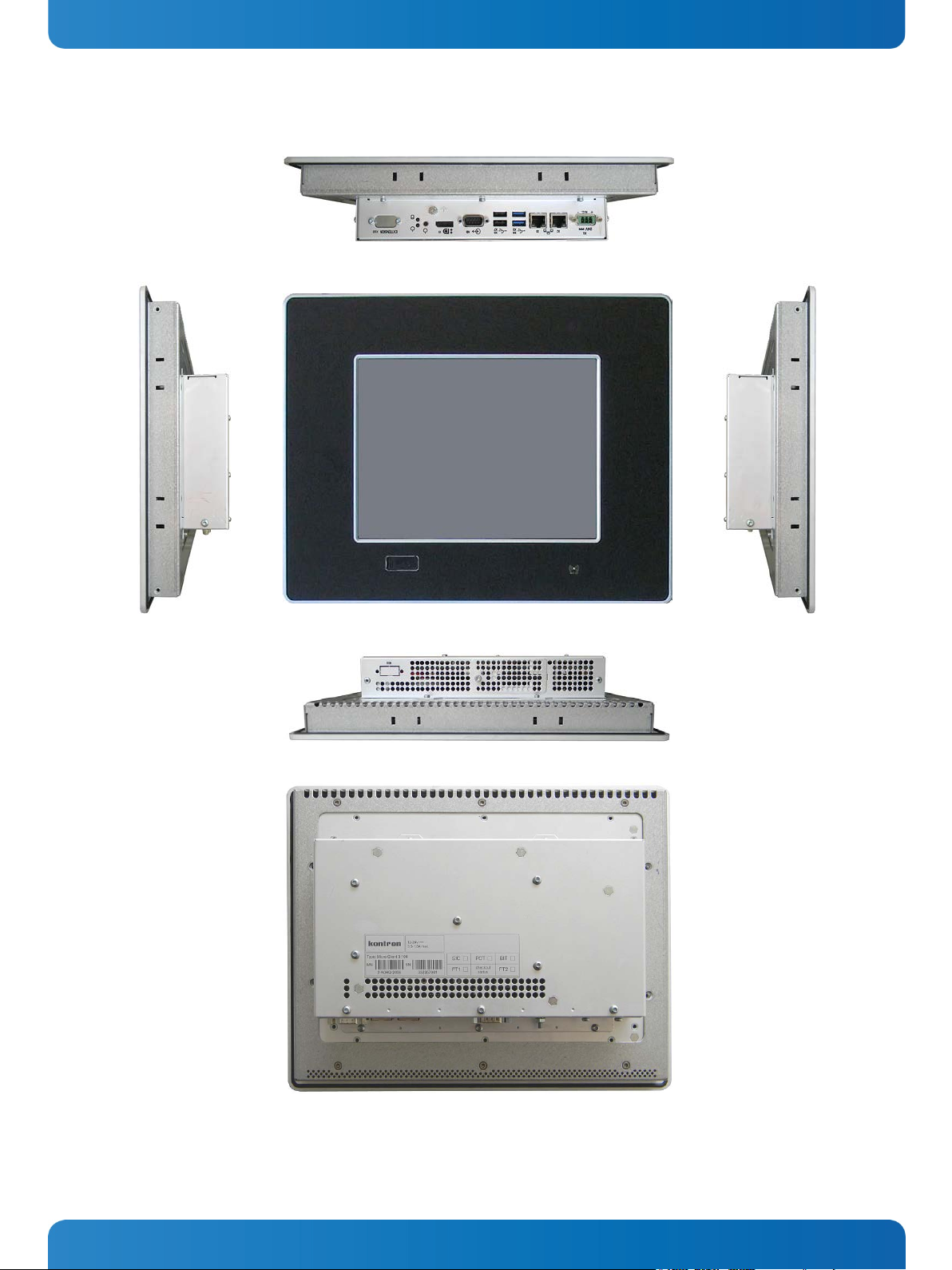
Fig. 1: Bottom view
Fig. 2: Right view
Fig. 3: Frontal view
Fig. 4: Left view
Fig. 5: Top view
Fig. 6: Rear view
7. Product Description Micro Client 3 – User’s Guide (Version 1.0)
In these pictures (Fig. 1 up to Fig. 6) the MC 3 system is shown as an MC 3 104 unit.
www.kontron.com 15
Page 18
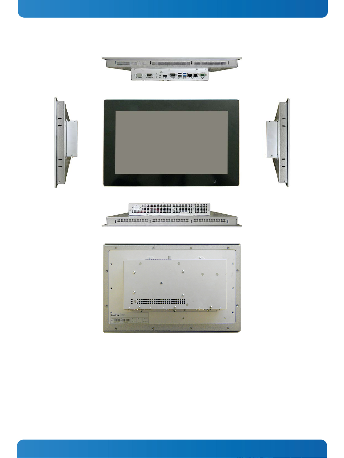
Fig. 7: Bottom view
Fig. 8: Right view
Fig. 9: Frontal view
Fig. 10: Left view
Fig. 11: Top view
Fig. 12: Rear view
7. Product Description Micro Client 3 – User’s Guide (Version 1.0)
In these pictures (Fig. 7 up to Fig. 12) the MC 3 system is shown as an MC 3W 156 unit.
16 www.kontron.com
Page 19
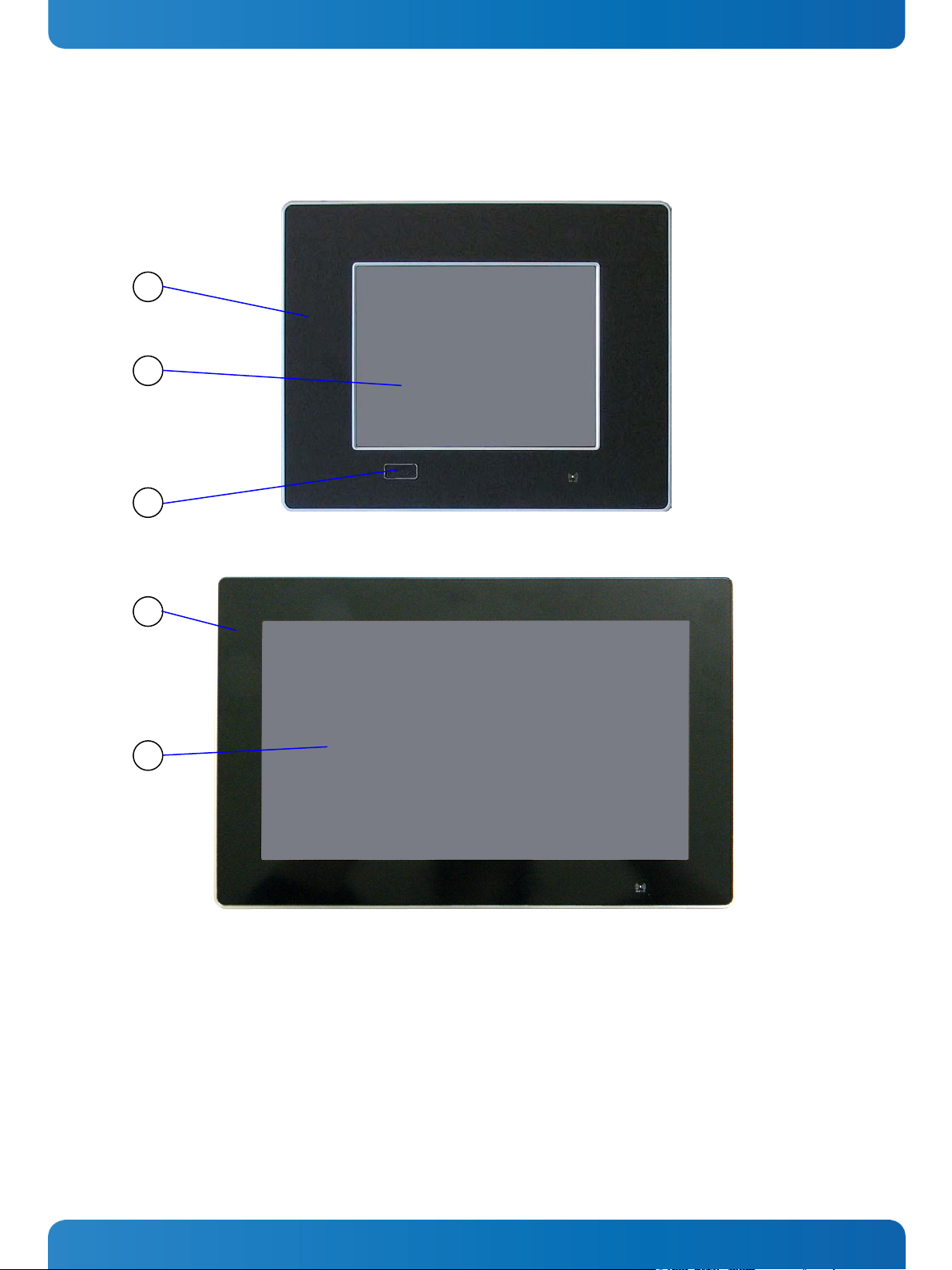
1 Front plate
3 Covered USB interface (available at MC3
3 1 2 1 4
7. Product Description Micro Client 3 – User’s Guide (Version 1.0)
7.1. Front Side View
Fig. 13: Frontal view of the MC 3 104/121/150/170 system (shown as a 10.4" display)
Legend for Fig. 13 and Fig. 14:
Fig. 14: Frontal view of the MC 3W 156 system
2 10.4"/12.1"/15"/17" TFT display with touch
screen
www.kontron.com 17
104/121/150/170 only)
4 15.6" TFT display with multitouch screen
Page 20

7. Product Description Micro Client 3 – User’s Guide (Version 1.0)
7.1.1. USB Interface Connector on the Front Side of the MC 3 104/121/150/170 Systems
This USB 2.0 connector allows you to connect different USB-compatible devices to the MC 3 system. The USB connector is
covered by an elastic captive rubber coat. The rubber coat prevents the penetration of fluid if no device is connected.
side USB connector is covered by the elastic captive rubber coat.
The USB interface connector is available only on the front side of the MC 3 104/121/150/170 system.
The MC 3 104/121/150/170 systems only comply with IP65 protection class at the front side, if the front
The MC 3W 156 system is not equipped with the USB interface on the front side.
7.1.2. MC 3 104/121/150/170 Systems - Front Plate Version
All MC 3 104/121/150/170 system versions are suitable for installation in an instrument panel or other cabinet.
At the front side of the 104/121/150/170 system, an aluminum front plate with polyester front foil is located.
For the outline dimensions of display unit of your system (MC 3 104/121/150/170) please refer to the chapter 9.3
“Mechanical Specifications”.
7.1.2.1. TFT Display 10.4"/12.1"/15"/17" with Touch Screen (resistive)
Depending on the ordered MC 3 system the built-in display is a 10.4"/12.1"/15"/17" size TFT display with corresponding
resistive touch screen. The touch screen is USB connected.
For technical specification of the built-in display refer to the chapter 9 “Technical Data”.
The display is equipped with a resistive touch screen. The touch screen offers the same degree of user comfort as the mouse
buttons.
The surface of the display is also mechanically protected through the touch screen. The touch screen (USB connected)
registers contacts of a finger or a pen and allows moving the mouse pointer. This functions only by integration of the
necessary software. The corresponding touch screen driver for your operating system is installed on your MC 3 system.
the touch screen surface.
The front panel (MC 3 104/121/150/170) and the touch screen are covered by a plastic overlay and care
should be taken when cleaning it (see the chapter 7.1.4 “Touch Screen Care and Cleaning”).
18 www.kontron.com
Do not use a hard or a pointed object (like screw drivers) to operate the touch screen, since it can damage
Page 21

7. Product Description Micro Client 3 – User’s Guide (Version 1.0)
7.1.3. Calibrating the Touch Screen (resistive)
Calibration serves two purposes:
Sets the active area of the touch screen
Aligns the active area of the touch screen to the screen’s image.
Before you calibrate the touch screen, let the system warm up for 30 minutes.
Calibration aligns the active touch-sensitive area of the touch screen with the image on the display. Calibration also
determines the edges of the screen’s image and locates the center of the touch screen. If the touch screen is not calibrated
properly, the active area of the touch screen may not be aligned with the screen’s image or may be unnecessarily small in
size. If necessary, in order to access the calibration routine, use an USB mouse.
7.1.3.1. Calibrate the Touch Screen for Windows
Windows
®
XP embedded
®
7 / Windows® 7 Embedded / Windows® Embedded Compact 7 /
The touch screen of your MC 3 system is factory calibrated. Run the calibration routine when an alignment problem exists
between the mouse pointer and the finger/stylus contact location on the screen. You can adjust the touch screen
calibration by performing the following steps:
Run the touch screen property sheet from the Start-Programs by clicking on “Configure Utility” in the “eGalax Touch”
menu entry:
Fig. 15: Hampshire TSHARC™ Control Panel
Select the “Tools” tab. Then select the “4 Points Calibration” Button (refer to Fig. 16 and Fig. 17) and touch the calibration
targets as accurately as possible.
www.kontron.com 19
Page 22

Fig. 16: Select “Tools” tab
Fig. 17: Select “4 Points Calibration”
Fig. 18: Touch the calibration targets and complete the calibration
7. Product Description Micro Client 3 – User’s Guide (Version 1.0)
Complete the calibration process by selecting the “OK” button.
20 www.kontron.com
Page 23

7. Product Description Micro Client 3 – User’s Guide (Version 1.0)
7.1.4. Touch Screen Care and Cleaning
cleaning it.
Mild detergent and water is recommended for cleaning. Use of strong solvents, which could attack paint or plastic, should
be avoided.
The plastic overlay or the touch screen surface is subject to burning and scaring from direct heat sources such as cigarettes.
The display front is sealed against dust, liquids, etc.
The front surface of the touch screen is protected by a flexible plastic foil, so care should be used to avoid using sharp
objects such as knife, pen or pencil tips. Sharp objects can permanently damage the functionality of the touch screen.
Units without a touch screen have a polycarbonate shield, which could be scratched by a sufficiently sharp object.
7.1.5. MC 3W 156 System - Front Plate
The MC 3W 156 system is suitable for installation in an instrument panel or other cabinet.
At the front side of the system, an aluminum front plate with integrated anti-glare glass plate and capacitive touch is
located.
For the outline dimensions of display unit of your system please refer to the chapter 9.3 “Mechanical Specifications”.
The front panel and the touch screen are covered by a plastic overlay and care should be taken when
7.1.5.1. TFT Display 15.6" Size with Touch Screen (capacitive)
Unlike the resistive touch displays, the capacitive touch screen needs no further calibration after factory calibration. Only
special, conductive styluses (not included) work with capacitive touch screens.
The capacitive touch screen is factory-calibrated and needs no recalibration.
When using a stylus (not included), make sure to use a special conductive stylus that works with
capacitive touch screens
www.kontron.com 21
Page 24

1 DC power connector
10 Optional interface (CAN-BUS and/or RS422/485 interfaces
13
13
11
14
12
1 4 5
8
10
2 3 9 6 7
15
13
11
15
12
13
10
1 4 6 5 9 2 8 3 13
14 7 10
7. Product Description Micro Client 3 – User’s Guide (Version 1.0)
7.2. Bottom View
Fig. 19: Bottom view of the MC 3 104
Fig. 20: Bottom view of the MC 3 156
Legend for Fig. 19 and Fig. 20:
2 2x Ethernet connector (RJ45) 10/100/1000 Mbps)
3 2x USB (3.0) connector (blue)
4 2x USB (2.0) connector
5 1x COM1 (RS232) serial port connector (DSUB, 9-pin)
6 1x DisplayPort
7 Grounding screw with lock washers
8 Power button
for MC 3 104/121/150/170 and MC 3W 156)
11 Display enclosure
12 Front panel of the system with seal at the rear side
13 Mounting slots for mounting clamps
14 Small mounting clamp with Allen screw (shown for the
MC 3 104)
15 Air openings on the display side
9 LED indicators (power and HDD)
22 www.kontron.com
Page 25

7. Product Description Micro Client 3 – User’s Guide (Version 1.0)
In the MC3 121/150/170 and MC 3W 156 systems up to three different modules for (RS422/485) or RS232
or CAN-BUS interfaces can be installed.
In the MC 3 104 systems two modules for (RS422/485) or RS232 or CAN-BUS interface can be installed.
7.2.1. Power and Grounding
7.2.1.1. DC In Power Connector
Fig. 21: Detail of the DC Power connector shown without Phoenix terminal
The MC 3/MC 3W system is supplied with a 3-pin Phoenix power connector terminal (refer to Fig. 40). The DC Power
connector (Fig. 21) provides the power connection of the
MC 3/MC 3W system to the main power source via a DC power
cable (not included). For pin-assignment of this connector refer to the chapter 10.1.1 “Power Connector”.
7.2.1.2. Grounding Screw (M4) with lock Washers
The chassis of the MC 3/MC 3W system must be grounded by establishing a large-area contact between the grounding stud
M4x10 (DIN7985) with 2x lock washer M4 (DIN6797) and nut M4 (Fig. 19, Fig. 20, pos. 7, and Fig. 22, pos. 4), and an
appropriate grounding connection point. The minimum cross section of the grounding conductor is 1mm
2
(AWG 18).
www.kontron.com 23
Page 26
nnected either from the DC main or the unit. Therefore, the DC power cord and its connectors must
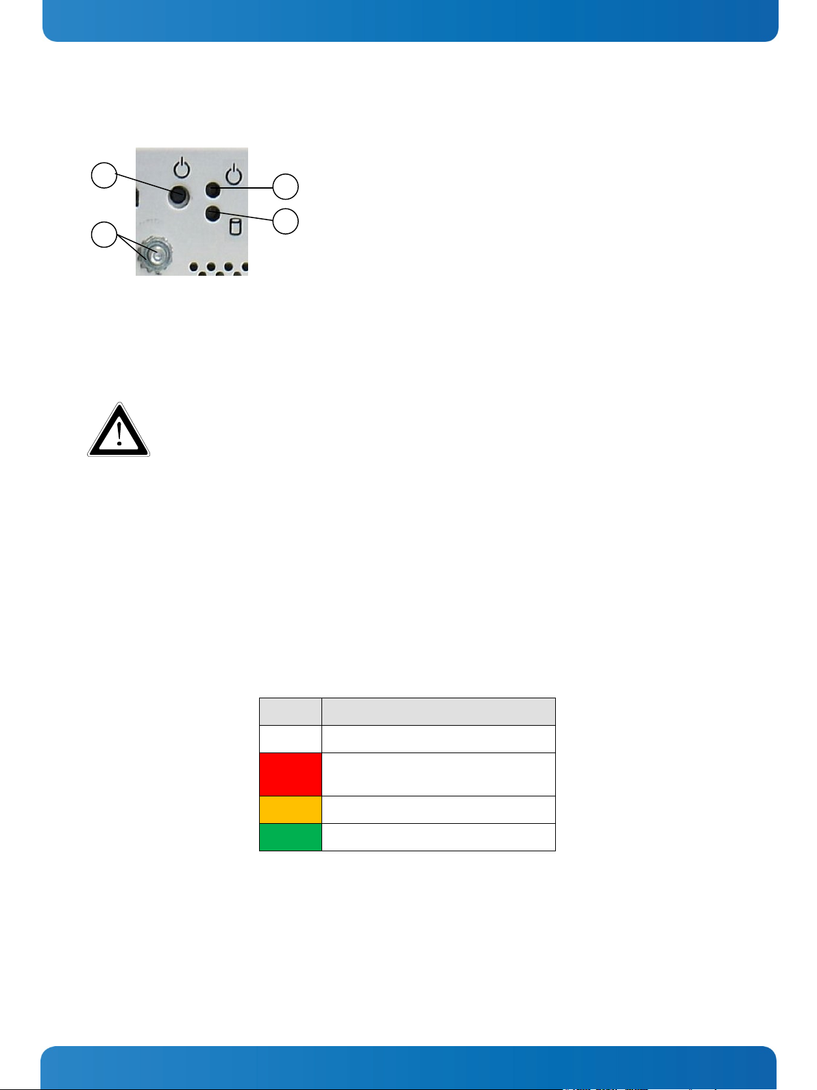
1 Power button
1
4 3 2
7. Product Description Micro Client 3 – User’s Guide (Version 1.0)
7.2.2. Power Button and Control Indicators
2 Power LED
3 HDD LED
Fig. 22: Controls of the MC 3 system (bottom rear side)
4 Grounding stud with lock washers
7.2.2.1. Power Button
The power button (Fig. 19,
Fig. 20, pos. 7, and Fig. 22, pos. 1) allows to power ON/OFF the system.
Even when the system is turned off via the power button there is still a standby-voltage of 5 V on the
SBC. The system is not completely disconnected from the main power supply by turning off via the
power button.
Hints for DC power connection:
The DC main power supply should be able to be switched off and on via a 2-pole isolating switch.
The unit is only completely disconnected from the DC main power supply, when the DC power cord is
disco
always remain easily accessible.
7.2.2.2. Power LED
The power LED (
Fig. 22, pos. 4) indicates the current system power state (S0, S3, S4, or S5) as shown in shown in Fig. 23.
The power LED will blink red if an error condition was detected (the system is held off). The color red is reserved for error
codes, only.
Color System State
Off
Red
Orange
Green
Power off or EC failure
System held off
(i.e. over-temperature, etc.)
System in S3/S4/S5
System in S0
Fig. 23: Color code for current system power state
An over-temperature condition has the highest of all priorities. The power button is deactivated as long as the temperature
is too high. To signalize this emergency state, the LED lights up red.
24 www.kontron.com
Page 27

7. Product Description Micro Client 3 – User’s Guide (Version 1.0)
7.2.2.3. Storage Drive Activity LED
The MC 3 /MC 3 W systems can be optionally equipped with a CF card and/or an SD card and/or an internal
2.5" HDD (SATA) and/or an MSATA module.
Refer to
Fig. 22, pos. 3 for the storage drive activity LED location. Depending on the system configuration and storage
drive/s activity this LED may be blinking as shown below:
Color Storage State
Off
Orange
Green
No activity on SATA / mSATA / SD-card / CF-card
SATA / mSATA activity
SD-card / CF-card activity
Note: activity on SATA / mSATA has a higher priority than SD-card / CF-card
Fig. 24: Color of the storage drive activity LED, depending on the system configuration
www.kontron.com 25
Page 28
1 DC power connector
5 COM1 (RS232) serial port connector
1 2 6 5 7 3 4
7. Product Description Micro Client 3 – User’s Guide (Version 1.0)
7.2.3. Interfaces (Rear, Bottom Side of the System)
Fig. 25: Detail with interfaces for MC 3 104 system
Fig. 26: Detail with interfaces for MC 3 121/150/170 and MC 3W 156 systems
Legend forFig. 25 and Fig. 26:
2 2x LAN (1Gbps) connector
3 2x USB 3.0 connector
4 2x USB 2.0 connector
6 Display Port connector
7 Optional interfaces (shown as CAN-BUS for
MC 3W 156 system)
7.2.3.1. LAN0 and LAN1 Ethernet Interface Connectors
These interface connectors (Fig. 19,
Fig. 20, pos. 5 and Fig. 25, Fig. 26 pos. 2) are provided as RJ45 sockets with integrated
LEDs and support a 10/100/1000 Mbps data transfer rate.
Ethernet LED States:
Left LED State Link Activity State Right LED State Link Speed
off Link not active Off 10 Base-T
yellow Link active green 100 Base-T
yellow (blinking) Link active green (flashing) 1000 base-T
7.2.3.2. USB Connectors
The system is equipped at the bottom side (rear) with two USB 2.0 and two USB 3.0 interface connectors (Fig. 19,
Fig. 20,
pos. 3, pos. 4 and Fig. 25, Fig. 26 pos. 3, pos. 4). These connectors provide connections for USB-compatible devices.
7.2.3.3. DisplayPort Interface Connector
An external (digital) monitor can be plugged into this interface (Fig. 19,
7.2.3.4. COM1 Serial Interface Connector
This RS232 connection (marked as COM1) (Fig. 19,
connectors (female) and provides connection (RS232) for serial devices.
26 www.kontron.com
Fig. 20, Fig. 25 and Fig. 26 pos. 6).
Fig. 20, pos. 4 and Fig. 25, Fig. 26 pos. 5) are available as 9-pin D-SUB
Page 29

Serial Communication Type
Transmitting<->receiving
SW1 Settings
DIP1
DIP2
DIP3
RS422 4-Channel Mode
-
OFF
OFF
OFF
RS485 4-Wire Mode (Bus-Master)
-
ON
OFF
ON
RS485 2-Wire Mode
Timeout
ON
ON
OFF
7. Product Description Micro Client 3 – User’s Guide (Version 1.0)
7.3. Optional Interfaces
The optional interfaces (Fig. 25, Fig. 26 pos. 7 and Fig. 30, Fig. 31, pos. 8) shown as CAN-BUS for MC 3 104 and as
RS422/485 interface for MC 3 121/150/170 and MC 3W 156 systems must be custom ordered. Depending on your
requirements, you can choose the type of the optional interface/s: RS232, RS422/485, RS422/485 isolated 1.5kV
CANopen, PROFIBUS, LPCtoCAN(SJA1000) adapter and Real Ethernet.
For MC 3 104 systems:
The optional interface locations (Fig. 25, pos. 7 and Fig. 30, pos. 8) can be fitted with:
up to two different interfaces: RS422/485 and/or CANopen, PROFIBUS
CANopen, PROFIBUS and/or RS232 and/or LPCtoCAN
or only Real ethernet
For MC 3 121/150/170/ and MC 3W 156 systems:
The optional interface locations (Fig. 26 pos. 7 and Fig. 31, pos. 8)can be fitted with:
up to three different interfaces: RS422/485 and/or CANopen, PROFIBUS
CANopen, PROFIBUS and/or RS232 and/or LPCtoCAN
or only Real ethernet
7.3.1. RS422/RS485 Serial Interface Connector/s
If one of the optional interfaces of your system is an RS422/485 serial interface (Fig. 19,
it is available as 9-pin D-SUB connector (female). The interface can be configured via an on-board DIP switch (SW1) for
RS422 or RS485 serial communication.
The optional settings (SW1) for RS485 mode communication allow the system’s operation either in full duplex mode or in
half duplex mode (see tables on the next page). While running in RS485 half duplex mode the system stays permanently in
a receiver mode. The switch to transmission mode will be done automatically. The user can determine if the automatic
mode switch to transmission mode should be triggered by the RTS-line or should be triggered by the last sent message
using the TxD line.
If triggered by RTS has been selected, then the RTS-signal must be activated by the application software before
transmission of the data packets starts; and RTS signal has to be disabled again after termination of data transmission.
If TxD line will be used for the mode transceiver switch process, the receiver device has to follow a timeout before starting
to send any data.
Fig. 27: Onboard DIP-Switch (SW1) with DP1 up to DP8 for RS422/RS485 serial communication settings
In order to configure this interface for serial communication (as RS422 or RS485) corresponding to your requirements, set
the switches of the DIP switch (SW1) to “ON” or “OFF” (factory settings are marked grey). For accessing the DIP switch refer
to the procedure described in the chapter 7.9.1 “Configuration of the RS422/RS485 Port”.
Fig. 20, Fig. 25 and Fig. 26 pos. 1)
RS485 2-Wire Mode RTS ON ON ON
Table 1: DIP1, DIP2 and DIP3 settings for serial communication type
www.kontron.com 27
Page 30

Termination Resistor for RS422 and RS485
SW1 Settings
DIP4
Deactivated
OFF
Activated
ON
Timeout
Min. Baud Rate
SW1 Settings
DIP5
DIP6
DIP7
DIP8
10.2ms
1200
OFF
OFF
OFF
OFF
9.6ms
OFF
OFF
OFF
ON
9.0ms
OFF
OFF
ON
OFF
8.4ms
OFF
OFF
ON
ON
7.8ms
OFF
ON
OFF
OFF
7.2ms
OFF
ON
OFF
ON
6.5ms
OFF
ON
ON
OFF
4.8ms
2400
ON
OFF
OFF
OFF
4.3ms
ON
OFF
OFF
ON
3.7ms
ON
OFF
ON
OFF
3.1ms
ON
OFF
ON
ON
2.5ms
4800
ON
ON
OFF
OFF
1.9ms
ON
ON
OFF
ON
1.2ms
9600
ON
ON
ON
OFF
0.6ms
19200
ON
ON
ON
ON
7. Product Description Micro Client 3 – User’s Guide (Version 1.0)
Table 2: DIP4 setting in order to activate or deactivate the termination resistor
5.9ms OFF ON ON ON
Table 3: DIP5, DIP6, DIP7 and DIP8 settings in order to set the needed timeout and min. baud rate
28 www.kontron.com
Page 31

Fig. 28: DIP-Switch of the LPCtoCAN Adapter
Fig. 29: Color legend used in the Table 4, Table 5 and Table 6:
ON
OFF
OFF
0x200 to 0x21F*
*These settings are not usable for Micro Client 3!
*These settings are not usable for Micro Client 3!
7. Product Description Micro Client 3 – User’s Guide (Version 1.0)
7.3.2. DIP-Switch Settings (SW1) for LPCtoCAN Adapter
The DIP-switch is for setting the SJA1000-base address, the SJA-interrupt, and the NVRAM operation mode.
Factory settings for one LPCtoCAN adapter
Factory settings for two LPCtoCAN adapters
7.3.2.1. SJA Base Address (SW1: 1-3)
Switch
Address Range
3 2 1
OFF OFF OFF 0x340 to 0x35F*
OFF OFF ON 0x320 to 0x33F*
OFF ON OFF 0x300 to 0x31F
OFF ON ON 0x220 to 0x23F*
ON OFF ON 0x140 to 0x15F*
ON ON OFF 0x120 to 0x13F*
ON ON ON 0x100 to 0x11F*
Table 4: SJA-Base Address Settings
7.3.2.2. SJA-Interrupt (SW1: 4-6)
Switch
6 5 4
OFF OFF OFF disabled*
OFF OFF ON 15*
OFF ON OFF 11*
OFF ON ON 10
ON OFF OFF 7*
ON OFF ON 5*
ON ON OFF 4*
ON ON ON 3*
Table 5: SJA-Interrupt Settings
IRQ
www.kontron.com 29
Page 32

OFF
ON
IO-mode
7. Product Description Micro Client 3 – User’s Guide (Version 1.0)
7.3.2.3. NVRAM-Operation Mode (SW1: 7-8)
Switch
Mode
8 7
OFF OFF disabled
ON OFF Memory at C0000
ON ON Memory at D0000
Table 6: NVRAM-Operation Mode Settings
30 www.kontron.com
Page 33

1 CF/SD card slot cover with captive screw
5 Screws that secure the cover on the top side
7 6 5
1
2 4 6 7 7
7
5
8
8 4 5 7 4 5 3 7 7 7 7
7
7
7
7. Product Description Micro Client 3 – User’s Guide (Version 1.0)
7.4. Top View
Fig. 30: Top side of the system (shown as MC 3W 156, with CF/SD card slot cover attached)
Fig. 31: Top side of the system (shown as MC 3 104, with CF/SD card slot cover removed)
Legend for Fig. 30 and Fig. 31:
2 CompactFlash™ slot (with CF card)
3 SD card slot
4 Air exhaust openings
6 Front panel with seal on the rear side
7 Mounting slots for mounting clamps
8 Cutout for optional interfaces
www.kontron.com 31
openings are not obstructed.
When powering on the MC 3 system, make sure that the air intake and exhaust
Page 34

7. Product Description Micro Client 3 – User’s Guide (Version 1.0)
7.4.1. CompactFlash™ Slot and SD card Slot
The system is equipped with a CompactFlash™ slot and an SD card slot. Both slots are located on the rear top side. The CF
slot accepts only CF cards type II.
Before installing or removing the Compact Flash™ card or the SD card, the MC 3 system must be powered
down and disconnected from the power source.
The MC 3 104/121/150/170 and MC3 156 systems are equipped with a cover in order to cover the CF/SD
slot, (refer to Fig. 30, pos. 1 and Fig. 31, pos. 2).
32 www.kontron.com
Page 35

Fig. 32: Right side shown as MC 3W 156 system
Fig. 33: Left side shown as MC 3W 156 system
Fig. 34: Right side of the MC 3 104 system
Fig. 35: Left side of the MC 3 104 system
1 Front panel of the system with seal at the rear side
4 Mounting slots with installed mounting clamp and Allen
1
2 5 5 6 6 1 3 3 6
4 4 1 4 4 2 3
4 4 5
3 5 2 6 1 4 4 2 5
5
7. Product Description Micro Client 3 – User’s Guide (Version 1.0)
7.5. Left and Right Side View
Legend for Fig. 32, Fig. 33, Fig. 34 and Fig. 35:
2 Enclosure of the display
3 System cover
www.kontron.com 33
Screw
5 Screws that secure the cover on the top and bottom side
6 Type label of the MC 3 system with C-UL Listing Mark
Page 36

1 Front panel of the system with seal at the rear side
5 Screws that secure the system cover on the rear side
2 7 3
1
5 8 1
3 5 2 6 9 2 2 4 2 2 2 2 2 2 2 2 9
4
3 3 2 7 6 2 2 2 10
8
10
7. Product Description Micro Client 3 – User’s Guide (Version 1.0)
7.6. Rear View
Fig. 36: Rear side of the system (shown as a MC 3W 156 system)
Fig. 37: Rear side of the system (shown as a MC 3 104 system)
Legend for Fig. 36 and Fig. 37:
2 Mounting clamp with Allen screw(s) for mounting to a
subframe
3 Threaded hole [marked red in the picture only (4x for
mounting the VESA® 100 compliant, adapter plate);
refer to the 7.6.1 “VESA
®
Mounting Plate (Option)”]
4 Interface side
34 www.kontron.com
6 Enclosure of the display
7 CF/SD card slot cover with captive screw
8 System cover
9 Type label of the system
10 Hot surface warning label
Page 37

7. Product Description Micro Client 3 – User’s Guide (Version 1.0)
The MC 3 system can be installed with the optional VESA
MC 3 104/121/150/170 is VESA
®
100 compliant (refer to Fig. 38).
®
100 compliant adapter plate.
MC 3W 156 is also VESA® 100 compliant (refer to Fig. 39).
7.6.1. VESA
®
Mounting Plate (Option)
The device is designed to be operated in vertical position (with the interfaces downwards) mounted to a VESA® 100
compliant mounting system.
Each of the VESA® 100 compliant mounting plates must be fastened to the appropriate
MC 3 system (refer to pos. 3, Fig. 36 and Fig. 37) with four M4x6 metric screws.
Do not use longer screws than the original screws provided (M4x6 metric). Using longer screws damage
the internal components of the system.
Please observe the warning label “Hot Surface” shown in Fig. 36 and Fig. 37on the rear side of the
cabinet. The MC 3/MC3W chassis may be hot during operation and should not be touched without taking
care.
The material on bottom surface of the enclosure interior where the MC 3/MC 3W is to be mounted, shall
keep at least flammability class UL 94-5VB. Don’t put flammable materials under the device.
Fig. 38: Rear and bottom view of the mounting plate VESA® 100 compliant for MC 3 104
www.kontron.com 35
Page 38

7. Product Description Micro Client 3 – User’s Guide (Version 1.0)
Fig. 39: Rear and bottom view of the mounting plate VESA® 75/100 for MC 3W 156
36 www.kontron.com
Page 39

1 3-pin Phoenix plug terminal
4 Marking “plus”
3
1 2 4
5
6
7. Product Description Micro Client 3 – User’s Guide (Version 1.0)
7.7. Installed SBC
Your MC 3/MC 3W system is equipped with the HMI Single Board Computer based on Intel® Atom™ CPU.
7.8. DC Power Connection
The MC 3/MC 3W system can be connected to a DC power source via a DC power cable (only the Phoenix power plug terminal
is included).
7.8.1. DC Power Connector
The MC 3 is delivered with the DC power plug terminal (3-pin Phoenix connector).
For DC connection prepare the connecting wires using the supplied Phoenix plug terminal.
1. Cut the required length two isolated wires [AWG18 (∅ up to 1 mm
2. Twist the striped wire-ends and tin it with solder.
3. Open the cover to have access to the slotted pan head screws.
The length of the DC connecting wires may not exceed 10 m.
Fig. 40: Phoenix power plug terminal with “plus” and “minus” marking (MC 3 104/156/170)
2 Cover over the slotted pan head screws
3 Marking “minus”
5 Location for inserting the “minus” wire
6 Location for inserting the “plus” wire
2
)] and strip each end 5 –7 mm.
4. Loosen the two slotted pan head screws (that correspond to the marked location “+” and “-“ of the DC plug terminal)
far enough so that you can insert the end of the prepared wires.
5. Insert the wires into the corresponding clamp of the Phoenix plug terminal. Make sure that you have the right polarity
of the connection (refer to Fig. 40).
6. Fasten the screws to secure the wires into the clamps of the plug terminal.
7. Close the cover.
www.kontron.com 37
The second end of each wire will be prepared as required for the connection to the DC power supply.
Page 40

7. Product Description Micro Client 3 – User’s Guide (Version 1.0)
7.9. Accessing Internal Components
This section contains important information that you must read before accessing the internal components. You must follow
these procedures properly when handling any board components of the system.
Before removing the cover of the MC 3/MC 3W in order to gain access to the internal components, the
system must be powered-down and the power cord has to be disconnected from the power source.
The system may only be opened in accordance with the description in this user’s guide for:
• Configuration of the RS422/RS485 interface.
These procedures have to be carried-out only by qualified specialist personnel.
It is not allowed to operate the system without installed cover.
Please observe the safety instruction for handling assemblies with static sensitive device.
Failure to take heed of this warning instruction can result in damage to the device.
Please observe the warning label “Hot Surface” shown in Fig. 36 and Fig. 37on the rear side of the
cabinet. The MC 3/MC3W chassis may be hot during operation and should not be touched without taking
care.
The material on bottom surface of the enclosure interior where the MC 3/MC 3W is to be mounted, shall
keep at least flammability class UL 94-5VB. Don’t put flammable materials under the device.
7.9.1. Configuration of the RS422/RS485 Port (MC 3 104/121/150/170, MC 3W 156)
In order to change the factory configuration of the RS422/RS485 port [factory settings: refer to the grey highlighted
settings of the SW1 (DIP1-DIP8) (Table 1, Table 2 and Table 3)] proceed as follows:
The new port configuration has to be set before the system is installed on a panel or into an industrial
cabinet. The system must be disconnected from the power source. Disconnect all peripherals. Before you
begin, ensure that you have a clean, flat and ESD-safe surface to work on.
1. Close all applications, shut down the system properly and disconnect the power cord from the power source.
Disconnect all peripherals.
2. The MC 3/MC 3W system should lay on a flat, clean surface with the front panel downwards. (Make sure that the display
surface is protected against scratching and damage).
3. a) For MC 3 104/121/150/170: Unscrew the 5x screws that secure the cover (refer to pos. 5, Fig. 31 and Fig. 37). Put
the screws aside for later use. Lift up the cover and put it aside.
b) For MC 3W 156: Unscrew the 5x screws that secure the cover (refer to pos. 5, Fig. 30, Fig. 32, Fig. 33 and Fig. 36). Put
the screws aside for later use. Lift up the cover and put it aside.
4. Locate the DIP switches inside the unit (refer to Fig. 41).
38 www.kontron.com
Page 41

Fig. 41: DIP1-DIP8 switches (shown with factorry settings)
DIP Switches (DIP1-DIP8)
7. Product Description Micro Client 3 – User’s Guide (Version 1.0)
5. By use of an insulated thin tool (e. g. screwdriver or a stylus) set the DIP switches to the up (for ON) or down (for OFF)
position corresponding the needed port configuration (refer to the Table 1, Table 2 and Table 3).
6. Replace carefully the cover to the system and screw it on with the retained screws.
7. Tighten the retained screws when the cover is firmly in place.
www.kontron.com 39
Page 42

Before using your system, you should first become familiar with the system components and check that
MC 3 104/121/150/170, MC 3W 156
PC
Display
10.4"/12.1"/15"/17"/15.6"
7. Product Description Micro Client 3 – User’s Guide (Version 1.0)
7.10. Getting started
The MC 3/MC 3W system is designed to be powered from a DC power source via a DC power cable (not included).
In order to use an AC power source as main power source, an AC/DC adapter (not included) can be ordered.
7.10.1. Connecting to Power
everything is connected properly.
It is recommended that the last cable attached to the system should be the power cable!
7.10.1.1. Connecting to DC Power Source
The MC 3/MC 3W system will be connected to DC power source using the DC power cable confectioned as described in the
7.8.1 “DC Power Connector” chapter.
Fig. 42: Connecting to DC power source
1. Connect the 3-pin DC power connector of the DC power cable to the appropriate DC power connector (refer to
pos. 2, Fig. 25 and Fig. 26) of the MC 3 system. The DC power connector of the system is on the rear bottom side and is
labeled “-24V DC+”. Make sure the connector is securely locked in place.
2. Ensure that the DC power source is switched off via an isolating switch, in order to ensure that no power is flowing from
the external power source during the connection procedure.
3. Connect the other end of the DC power cable to the terminals of the 24V DC power source. Ensure that the power
connections maintain the proper polarity.
4. Switch on the isolating switch in order to apply voltage to the terminals of the power source (cable wires).
Behaviour of the MC 3/MC 3W systems
When turning on power to the system via the isolating switch, the MC 3 system will immediately boot-up
the installed operating system.
Hints for DC power connection:
The DC power source should be able to be switched off and on via an isolating switch.
The unit is only completely disconnected from the DC main power source, when the DC power cord is
disconnected either from the power source or the unit. Therefore, the DC power cord and its connectors
must always remain easily accessible.
40 www.kontron.com
Page 43

7. Product Description Micro Client 3 – User’s Guide (Version 1.0)
7.11. Operating System and Hardware Component Drivers
Your MC 3/MC 3W system can be supplied either with or without a pre-installed operating system.
If you have ordered your system with a pre-installed operating system, all drivers are installed in accordance with the
system configuration ordered (optional hardware components). Your system is fully operational at the first start-up.
If you have ordered a MC 3/MC 3W system without a pre-installed operating system, because you want to install it yourself,
please pay attention to the following information:
You can download the relevant information about operating systems, boot devices and drivers for the
installed hardware from our web site at www.kontron.com
The corresponding driver (depending on the installed operating system) for the touch screen controller is
available on our website by selecting the “Downloads” tab of the Micro Client 3 product page.
by selecting the product name (designation).
www.kontron.com 41
Page 44

1 Enclosure of the 10.4" display
4 Example of subframe for system installation
2
2 2 5 6 2
4 2 4 1 2 3 6
3
7. Product Description Micro Client 3 – User’s Guide (Version 1.0)
7.12. MC 3/MC 3W System Mounting to a Subframe or Panel
The system configurations come in the delivering status without assembled mounting clamps and the corresponding Allen
Screws. In order to mount the system to a subframe or panel, refer to Fig. 43 or Fig. 44, depending on the system ordered.
Fig. 43: Detail with mounting clamps and a subframe
(shown with a MC 3 104 system)
Fig. 44: Detail with mounting clamps and a subframe
(shown with a MC 3W 156 system)
Legend for Fig. 43 and Fig. 44:
2 Mounting clamp with 1x screw (used for mounting of
MC 3 104/ MC 3W 156 into a subframe/panel)
3 Cover of CompactFlash™/SD card slot
5 Enclosure of the 15.6" display
6 Mounting clamp with 2 screws (used for mounting of the
MC 3 121/150/170 and MC 3W 156 into a
subframe/panel)
In order to ensure IP65 front sealing against dust and water, mount the system on a non-textured
surface. Before you install the MC 3 system into a panel or a subframe for industrial cabinet, verify the
perfect condition of the seal at the rear of the front plate. The seal has to be in place without
injury/defects and dirt.
Please observe the warning label “Hot Surface” shown in Fig. 36 and Fig. 37on the rear side of the cabinet.
The MC 3/MC3W chassis may be hot during operation and should not be touched without taking care.
The material on bottom surface of the enclosure interior where the MC 3/MC 3W is to be mounted, shall
keep at least flammability class UL 94-5VB. Don’t put flammable materials under the device.
42 www.kontron.com
Page 45

7. Product Description Micro Client 3 – User’s Guide (Version 1.0)
The mounting clamps with screws (supplied), allow the easy and fast mounting of the MC 3 into an instrument panel or wall
panel.
Dimension for:
Rear side enclosure
(W x H x D)
[mm]
Cut-Out for Mounting
into a Panel (W x H)
Requirements for
Mounting
Metal mounting
panel thickness for
proper mounting
Used clamps with
screws for mounting
the MC 3
104/156/170
device to a subframe
or panel
Required Tool
Proper Torque
Mounting Position
Table 7: Requirements for the MC 3 104/121/150/170 and MC 3W 156 mounting into a subframe/panel
Micro Client 3 Micro Client 3W
104 121 150 170 156
295x234x63.75 324.5x263.5x62.5 406.8x311.4x65.5 416x356x64.5 398x249x63.5
297x236[mm]
11.69"x9.29"
1.5 – 6.5 [mm]
" - 0.26"
0.06
8x
327x266[mm]
12.87"x10.4"
1.5 – 5.5 [mm]
0.06" - 0.22"
6x
409x313[mm]
16.10"x12.32"
420x358[mm]
16.53"x 14.09"
1.5 - 7 [mm]
0.06" - 0.28"
8x
1.5 – 9.5 [mm]
0.06" - 0.37"
8x
400x251[mm]
14.75"x9.88"
1.5 - 7 [mm]
0.06" - 0.28"
4x
4x
Allen Wrench 2 mm
Tighten the screws with a torque of 0.5 Nm
Ensure the vertical and horizontal alignment of the system.
To mount the system to a subframe or to a panel, follow these steps:
1. Assemble the mounting clamp/s with the Allen Screw/s (included).
2. Depending on the dimension of the display enclosure of your system, cut a hole in the panel/subframe (refer to
Table 7 for the panel cut-out dimensions). The panel where you intend to attach the system must be accessible from
both front and rear side.
3. The system must be turned off and disconnected from the power source and peripherals.
4. Insert the system into the panel cut-out from the panel/subframe front.
5. In order to ensure the protection class IP65 on the front side in the installed condition, the contact surface with the
seal must be clean and flush.
6. Ensure the vertical and horizontal alignment of the system.
Fasten the MC 3/MC 3W system from the rear using the mounting clamps.
5. Hook the mounting clamps with screws from the rear side of the panel into the corresponding pairs of slots of the
enclosure.
7. The system must be attached firmly with the screws. Tighten the screws with a torque of 0.5 Nm (refer to Table 7 for the
mounting requirements).
www.kontron.com 43
Page 46

8. Maintenance and Prevention Micro Client 3 – User’s Guide (Version 1.0)
8. Maintenance and Prevention
Kontron Europe systems require minimal maintenance and care to keep them operating correctly.
Occasionally wipe the system with a soft dry cloth.
You should only remove persistent dirt by use of a soft, slightly damp cloth (use only a mild detergent).
For the touch screen cleaning refer to the chapter 7.1.4. “Touch Screen Care and Cleaning”.
44 www.kontron.com
Page 47

Resolution
800 x 600
1024 x 768
1024 x 768
1280 x 1024
1366 x 768
Colour depth
262k/16.2M
262k/16.2M
262k/16.2M
16.7 M
16.7 M
Backlight
LED
LED
LED
LED
LED
Brightness cd/m2
450
500
400
350
300
Contrast ratio
700:1
700:1
700: 1
1000: 1
500:1
Memory: up to 4 GB
Power Button
USB Port
Interfaces
USB 2.0
USB 3.0
Ethernet
Serial Port RS232
Socket for PCIe Mini card
Socket for Mini SATA Card
CF and SD Card Reader
9. Technical Data Micro Client 3 – User’s Guide (Version 1.0)
9. Technical Data
Features for
TFT LCD
Display
Touch Screen
SBC with Intel® Atom™
Processor D2550 1.86 GHz
(Socket 1x 204-pin DDR3)
Power LED
HDD LED
with elastic captive rubber
coat
Screen size 10.4" 12.1" 15" 17" 15.6"
(H x V) [pixel]
(on the front side)
Micro Client 3
104 121 150 170
(SVGA)
(XGA)
resistive analog
(XGA)
5 wire
1x
(SXGA)
Micro Client 3W
156
(WXGA)
PCAP
capacitive
Not available
(on the bottom side)
(10/100/1000Mbps)
DisplayPort 1x 1x
(COM1)
(on board)
(on board)
(Option)
(internal factory installed)
The table is continued on the next page.
2x 2x
2x 2x
2x 2x
1x 1x
1x 1x
1x 1x
1x 1x
www.kontron.com 45
Page 48

Storage Media (Option)
2.5" HDD* or 2.5" SSD
mSATA SSD
CF card, ext. accessible
SD card , ext. accessible
SIM card, int. accessible
Extension Slots for optional
Protection Class
9. Technical Data Micro Client 3 – User’s Guide (Version 1.0)
Features for
but one always factory installed
(only if CF card reader installed)
(only if CF card reader installed)
(only if CF card reader installed)
Interfaces
Optional Interfaces:
Serial Port RS422/485*
RS422 (default)
[configurable via internal
DIP Switch (SW1)] or
Serial Port (COM2)
(RS232) or
CAN-BUS
*
Port
(front side)
IP 65 according IEC 60529
Micro Client 3
104 121 150 170
Micro Client 3W
156
1x 1x
1x 1x
1x 1x
1x 1x
1x 1x
2x 3x 3x 3x 3x
up to 2x up to 3x up to 3x up to 3x up to 3x
BIOS
Operating System
DC Power Connector
(3-Pin), (on the rear bottom side)
DC Power Terminal (3-Pin)
Mounting Clamps
(for one screw)
Mounting Clamps
Refer to the Datasheet for Micro Client 3 on our Website www.kontron.com
8x --- --- --- 4x
--- 6x 8x 8x 4x
AMI BIOS
1x 1x
1x 1x
(for 2 screws)
Screw for Mounting Clamps
8x 12x 16x 16x 12x
The table is continued on the next page.
(*see “Operating Temperature” in chapter 9.2 “Environmental Specifications”.)
46 www.kontron.com
Page 49

Optional Parts
VESA® 100 compliant
9. Technical Data Micro Client 3 – User’s Guide (Version 1.0)
Features for
Mounting Plate
CF Card (Type II)
2.5" SATA HDD
Micro Client 3
104 121 150 170
Micro Client 3W
156
www.kontron.com 47
Page 50

9. Technical Data Micro Client 3 – User’s Guide (Version 1.0)
9.1. Electrical Specifications
9.1.1. Electrical Specifications for MC 3 104/121/150/170/3W 156 System
System Type Product Designation Input
MC 3 104 24VDC (+/- 20% = 18 – 30VDC)
0.7A
Nom (~20W)
MC 3 121 24VDC (+/- 20% = 18 – 30VDC)
0.8A
Nom (~22W)
Micro Client 3
MC 3 150 24VDC (+/- 20% = 18 – 30VDC)
(MC 3)
MC 3 170 24VDC (+/- 20% = 18 – 30VDC)
MC 3W 156 24VDC (+/- 20% = 18 – 30VDC)
9.2. Environmental Specifications
Thermal Management
Operating Temperature
Storage/Transit Temperature
Operating Rel. Humidity
Storage/Transit Rel. Humidity
Operating Altitude
passive cooling (for CPU and system)
0 … +50 °C (32 … 122 °F) for MC 3 104/121/150/170
0 … +55 °C (32 … 131 °F) for MC 3W 156 (*options : max. 50 °C)
-10 … +60 °C (14 … 140 °F)
10% to 90% @ 35 °C, non-condensing
10% to 90% @ 35 °C, non-condensing
Up to 2,000 m (6,600 ft)
0.95A
1.8A
Nom (~45W)
1.05A
Nom (~30W)
Nom (~32W)
Storage / Transit Altitude
Operating Shock
Storage / Transit Shock
Operating Vibration
Storage / Transit Vibration
Protection Class
Up to 4,600 m (15,000 ft)
15 G, 11 ms duration, half-sinus
30 G, 11 ms duration, half-sinus
10–500 Hz: 1.0 G/3axis
10–500 Hz: 2.0 G/3axis
IP65 (Front Panel Side), IP20 (Rear)
48 www.kontron.com
Page 51

9. Technical Data Micro Client 3 – User’s Guide (Version 1.0)
9.3. Mechanical Specifications
9.3.1. Dimensions for MC 3 104/121/150/170 and MC 3W 156
Dimension for MC 3 104 MC 3 121 MC 3 150 MC 3 170 MC 3W 156
Height
Width
Depth (total)
Depth (without
front plate)
Weight
257 mm
(10.118")
318 mm
(12.520")
69 mm
(2.71")
64 mm
(2.51")
3.5 kg
(7.716 lbs)
286 mm
(11.260")
347 mm
(13.661")
67.5 mm
(2.658")
62.5 mm
(2.461")
4.5 kg
(9.921 lbs)
334 mm
(13.150")
429 mm
(16.890")
70.5 mm
(2.758")
65.5 mm
(2.579")
6.5 kg
(14.33 lbs)
379 mm
(14.921")
441 mm
(17.362")
69.5 mm
(2.697")
64.5 mm
(2.539")
7.5 kg
(16.535 lbs)
270 mm
(10.630")
419 mm
(16.496")
68.5 mm
(2.204")
63.5 mm
(2.500")
4.5 kg
(9.921 lbs)
Fig. 45: Frontal view of the MC 3 104 system
www.kontron.com 49
Page 52

9. Technical Data Micro Client 3 – User’s Guide (Version 1.0)
Fig. 46: Frontal view of the MC 3 121 system
Fig. 47: Frontal view of the MC 3 150 system
50 www.kontron.com
Page 53

9. Technical Data Micro Client 3 – User’s Guide (Version 1.0)
Fig. 48: Frontal view of the MC 3 170 system
www.kontron.com 51
Page 54

9. Technical Data Micro Client 3 – User’s Guide (Version 1.0)
Fig. 49: Frontal view of the MC 3W 156 system
52 www.kontron.com
Page 55

MC 3 121 - rear view
MC 3 104 - rear view
9. Technical Data Micro Client 3 – User’s Guide (Version 1.0)
MC 3 104 – right side view
MC 3 121 – right side view
www.kontron.com 53
Page 56

MC 3 170
MC 3 150 – right side view
MC 3 170 - rear view
MC 3 150 - rear view
9. Technical Data Micro Client 3 – User’s Guide (Version 1.0)
– right side view
54 www.kontron.com
Page 57

MC 3W 156 - rear view
MC 3W 156
9. Technical Data Micro Client 3 – User’s Guide (Version 1.0)
– right side view
www.kontron.com 55
Page 58

9. Technical Data Micro Client 3 – User’s Guide (Version 1.0)
9.4. CE Directives and Standards
CE Directives
Low Voltage Directive
(Electrical Safety)
EMC Directive 2004/108/EC
RoHS II Directives 2011/65/EU
Electrical Safety Standards
EUROPE
USA
CB Scheme
EMC Standards
EUROPE Generic standards - Emission standard for
2006/95/EC
EN 60950-1: 2006
UL 60950-1:2006 cULus Listed
IEC 60950-1:2005 CB Certificate
for MC 3 104/121/150/170
residential, commercial and light-industrial
environments (Emission):
EN 61000-6-3: 2007 +A1:2010
Emission of Information technology
equipment – Radio disturbance
characteristics – Limits and methods of
measurement:
EN 55022:2010 Class B
Standards
for MC 3W 156
Generic standards - Emission standard for
residential, commercial and light-industrial
environments (Emission):
EN 61000-6-3: 2007 +A1:2010
Emission of Information technology
equipment – Radio disturbance
characteristics – Limits and methods of
measurement:
EN 55022:2010 Class B
ITE - Immunity characteristics - Limits and
methods of measurement
EN55024: 2010
Generic standards - Immunity for industrial
environments (Immunity):
EN 61000-6-2: 2005
U.S.A.
Canada
56 www.kontron.com
FCC 47 CFR Part 15, Class A
ICES-003 class A
ITE - Immunity characteristics - Limits and
methods of measurement
EN55024: 2010
Generic standards - Immunity for industrial
environments (Immunity):
EN 61000-6-2: 2005
FCC 47 CFR Part 15, Class A
ICES-003 class A
Page 59

10. Standard Interfaces – Pin Assignments Micro Client 3 – User’s Guide (Version 1.0)
10. Standard Interfaces – Pin Assignments
Low-active signals are indicated by a minus sign.
10.1.1. Power Connector
Pin Signal Name 3-pin POWER SUBCON (male)
1 0V input (-24 VDC polarity on the unit)
2 NC
3 +24 VDC (input)
10.1.2. Serial interface COM (RS232)
Pin Signal Name 9-pin D-SUB Connector (male)
1 DCD (Data Carrier Detect)
2 RXD (Receive Data)
3 TXD (Transmit Data)
4 DTR (Data Terminal Ready)
5 GND (Signal Ground)
6 DSR (Data Set Ready)
7 RTS (Request to Send)
8 CTS (Clear to Send)
9 RI (Ring Indicator)
www.kontron.com 57
Page 60
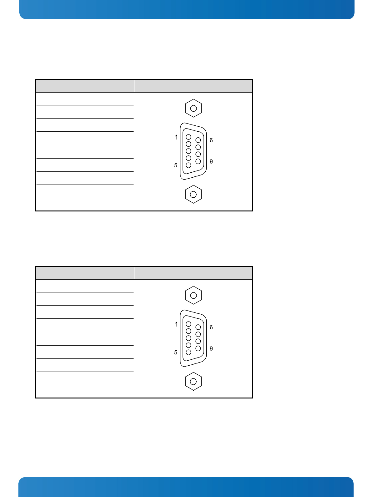
10. Standard Interfaces – Pin Assignments Micro Client 3 – User’s Guide (Version 1.0)
10.1.3. Serial Port (RS422/RS485) configured as RS422 (4-Channel Mode)
Refer to the chapter 7.3.1 “RS422/RS485 Serial Interface Connector/s”, Table 1, Table 2 and Table 3.
Pin Signal Name 9-pin D-SUB Connector (female)
1 TxD- (Transmit Data-)
2 RxD+ (Receive Data+)
3 TxD+ (Transmit Data+)
4 RxD- (Receive Data-)
5 GND (Signal Ground)
6 RTS- (Request to Send-)
7 RTS+ (Request to Send+)
8 CTS+ (Clear to Send+)
9 CTS- (Clear to Send-)
10.1.4. Serial Port (RS422/RS485) configured as RS485 (4-Wire Mode), full duplex, (Bus-Master)
Refer to the chapter 7.3.1 “RS422/RS485 Serial Interface Connector/s”, Table 1, Table 2 and Table 3.
Pin Signal Name 9-pin D-SUB Connector (female)
1 TxD- (Transmit Data-)
2 RxD (Receive Data+)
3 TxD+ (Transmit Data+)
4 RxD- (Receive Data-)
5 GND (Signal Ground)
6 NC
7 NC
8 NC
9 NC
58 www.kontron.com
Page 61

10. Standard Interfaces – Pin Assignments Micro Client 3 – User’s Guide (Version 1.0)
10.1.5. Serial Port (RS422/RS485) configured as RS485 (2-Wire Mode), half duplex
Refer to the chapter 7.3.1 “RS422/RS485 Serial Interface Connector/s”, Table 1, Table 2 and Table 3.
Pin Signal Name 9-pin D-SUB Connector (female)
1 Data-
2 NC
3 Data+
4 NC
5 GND (Signal Ground)
6 NC
7 NC
8 NC
9 NC
10.1.6. CAN Connector
Refer to the chapter 7.3.2 “DIP-Switch Settings (SW1) for LPCtoCAN Adapter”.
Pin Signal Name 9-pin D-SUB Connector (male)
1 NC
2 CANL (galavic separated)
3 CAN0V (galavic separated)
4 NC
5 NC
6 NC
7 CANH (galavic separated)
8 NC
9 NC
case GND
www.kontron.com 59
Page 62

10. Standard Interfaces – Pin Assignments Micro Client 3 – User’s Guide (Version 1.0)
10.1.7. DP Connector (DisplayPort)
Pin Signal Name 20-pin DP Connector
1 ML LANE 0+
2 GND (ML LANE 0)
3 ML LANE 0-
4 ML LANE 1+
5 GND (ML LANE 1)
6 ML LANE 1-
7 ML LANE 2+
8 GND (ML LANE 2)
9 ML LANE 2-
10 ML LANE 3+
11 GND (ML LANE 3)
12 ML LANE 3-
13 AUX_SEL#
14 Pull-down to GND
15 AUX CH+
16 GND (AUX CH)
17 AUX CH-
18 Hotplug
19 GND (GND_DDC)
20 +3.3V (DDC EEPROM power)
500mA fused
10.1.8. USB Port
Pin Signal Name 4-pin USB Connector
Type A Version 2.0
1 VCC
2 Data-
3 Data+
4 GND
60 www.kontron.com
Page 63

11. Technical Support Micro Client 3 – User’s Guide (Version 1.0)
11. Technical Support
For technical support, please contact our Technical Support department:
e-mail: support@kontron.com
Web: http://www.kontron.com/support
Make sure you have the following information on hand when you call:
• the unit part id number (PN),
• the serial number (SN) of the unit; the serial number can be found on the type label, placed on the rear side of the
system.
Be ready to explain the nature of your problem to the service technician.
If you have questions about Kontron Europe or our products and services, you can reach us by e-mail or at:
www.kontron.com .
11.1. Returning Defective Merchandise
Please follow these steps before you return any merchandise to Kontron Europe:
1. Download the corresponding form for returning a device with an RMA No. [RMA (Return of Material Authorization)]
from our website www.kontron.com / Support / RMA Information.
You also can contact our Customer Service department to obtain an RMA No.:
e-Mail: service@kontron.com
2. Ensure that you have received an RMA number from Kontron Customer Services before returning any device. Write this
number clearly on the outside of the package.
3. Describe the fault that has occurred.
4. Please provide the name and telephone number of a person we can contact to obtain more information, where
necessary. Where possible, please enclose all the necessary customs documents and invoices.
5. When returning a device:
• Pack it securely in its original box.
• Enclose a copy of the RMA form with the consignment.
Corporate Offices
Europe, Middle East & Africa
Oskar-von-Miller-Str. 1
85386 Eching/Munich
Germany
Tel.: +49 (0)8165/ 77 777
Fax: +49 (0)8165/ 77 219
info@kontron.com
North America
14118 Stowe Drive
Poway, CA 92064-7147
USA
Tel.: +1 888 294 4558
Fax: +1 858 677 0898
info@us.kontron.com
Asia Pacific
17 Building,Block #1,ABP.
188 Southern West 4th Ring
Beijing 100070, P.R.China
Tel.: + 86 10 63751188
Fax: + 86 10 83682438
info@kontron.cn
www.kontron.com 61
 Loading...