

Page 1

USER GUIDE
www.kontron.com // 1
KBox A-103
Doc. User Guide, Rev. 3.0
Doc. ID: 1057-0976
Page 2

KBox A-103 – User Guide, Rev. 3.0
This page has been intentionally left blank
www.kontron.com // 2
Page 3

KBox A-103 – User Guide, Rev. 3.0
KBOX A
-103 - USER GUIDE
Disclaimer
Kontron would like to point out that the information contained in this user guide may be subject to alteration,
particularly as a result of the constant upgrading of Kontron products. This document does not entail any guarantee
on the part of Kontron with respect to technical processes described in the user guide or any product characteristics
set out in the user guide. Kontron assumes no responsibility or liability for the use of the described product(s),
conveys no license or title under any patent, copyright or mask work rights to these products and makes no
representations or warranties that these products are free from patent, copyright or mask work right infringement
unless otherwise specified. Applications that are described in this user guide are for illustration purposes only.
Kontron makes no representation or warranty that such application will be suitable for the specified use without
further testing or modification. Kontron expressly informs the user that this user guide only contains a general
description of processes and instructions which may not be applicable in every individual case. In cases of doubt,
please contact Kontron.
This user guide is protected by copyright. All rights are reserved by Kontron. No part of this document may be
reproduced, transmitted, transcribed, stored in a retrieval system, or translated into any language or computer
language, in any form or by any means (electronic, mechanical, photocopying, recording, or otherwise), without the
express written permission of Kontron. Kontron points out that the information contained in this user guide is
constantly being updated in line with the technical alterations and improvements made by Kontron to the products
and thus this user guide only reflects the technical status of the products by Kontron at the time of publishing.
Brand and product names are trademarks or registered trademarks of their respective owners.
©2018 by Kontron S&T AG
Kontron S&T AG
Lise-Meitner-Str. 3-5
86156 Augsburg
Germany
www.kontron.com
www.kontron.com // 3
Page 4

KBox A-103 – User Guide, Rev. 3.0
Intended Use
THIS DEVICE AND ASSOCIATED SOFTWARE ARE NOT DESIGNED, MANUFACTURED OR INTENDED FOR USE
OR RESALE FOR THE OPERATION OF NUCLEAR FACILITIES, THE NAVIGATION, CONTROL OR
COMMUNICATION SYSTEMS FOR AIRCRAFT OR OTHER TRANSPORTATION, AIR TRAFFIC CONTROL, LIFE
SUPPORT OR LIFE SUSTAINING APPLICATIONS, WEAPONS SYSTEMS, OR ANY OTHER APPLICATION IN A
HAZARDOUS ENVIRONMENT, OR REQUIRING FAIL-SAFE PERFORMANCE, OR IN WHICH THE FAILURE OF
PRODUCTS COULD LEAD DIRECTLY TO DEATH, PERSONAL INJURY, OR SEVERE PHYSICAL OR
ENVIRONMENTAL DAMAGE (COLLECTIVELY, "HIGH RISK APPLICATIONS").
You understand and agree that your use of Kontron devices as a component in High Risk Applications is entirely at
your risk. To minimize the risks associated with your products and applications, you should provide adequate design
and operating safeguards. You are solely responsible for compliance with all legal, regulatory, safety, and security
related requirements concerning your products. You are responsible to ensure that your systems (and any Kontron
hardware or software components incorporated in your systems) meet all applicable requirements. Unless otherwise
stated in the product documentation, the Kontron device is not provided with error-tolerance capabilities and cannot
therefore be deemed as being engineered, manufactured or setup to be compliant for implementation or for resale as
device in High Risk Applications. All application and safety related information in this document (including application
descriptions, suggested safety measures, suggested Kontron products, and other materials) is provided for reference
only
.
www.kontron.com // 4
Page 5

KBox A-103 – User Guide, Rev. 3.0
Revision History
Revision Brief Description of Changes Date of Issue Author/
Editor
1.0 Initial Issue 2016-Jan-27 MK
2.0 New Corporate Design; legal and safety information
updated, BIOS chapter reworked, Linux note added, pinout of GPIO header added, COM port configuration
information added, errors corrected
3.0 CE Directives and Standards updated 2018-Sep-27 MK
2017-Aug-03 MK
Terms and Conditions
Kontron warrants products in accordance with defined regional warranty periods. For more information about
warranty compliance and conformity, and the warranty period in your region, visit http://www.kontron.com/termsand-conditions.
Kontron sells products worldwide and declares regional General Terms & Conditions of Sale, and Purchase Order
Terms & Conditions. Visit http://www.kontron.com/terms-and-conditions
.
For contact information, refer to the corporate offices contact information on the last page of this user guide or visit
our website CONTACT US.
Customer Support
Find Kontron contacts by visiting: http://www.kontron.com/support.
Customer Service
As a trusted technology innovator and global solutions provider, Kontron extends its embedded market strengths into
a services portfolio allowing companies to break the barriers of traditional product lifecycles. Proven product
expertise coupled with collaborative and highly-experienced support enables Kontron to provide exceptional peace of
mind to build and maintain successful products.
For more details on Kontron’s service offerings such as: enhanced repair services, extended warranty, Kontron
training academy, and more visit http://www.kontron.com/support-and-services/services
.
Customer Comments
If you have any difficulties using this user guide, discover an error, or just want to provide some feedback, contact
Kontron support
revised user guide on our website.
. Detail any errors you find. We will correct the errors or problems as soon as possible and post the
www.kontron.com // 5
Page 6

Symbols
V) when touching
. Failure to observe the precautions indicated and/or
This symbol and title inform that the electronic boards and their components are sensitive
to static electricity. Care must therefore be taken during all handling operations and
The following symbols may be used in this user guide
DANGER indicates a hazardous situation which, if not avoided,
will result in death or serious injury.
WARNING indicates a hazardous situation which, if not avoided,
could result in death or serious injury.
NOTICE indicates a property damage message.
CAUTION indicates a hazardous situation which, if not avoided,
may result in minor or moderate injury.
Electric Shock!
This symbol and title warn of hazards due to electrical shocks (> 60
products or parts of products
prescribed by the law may endanger your life/health and/or result in damage to your
material.
KBox A-103 – User Guide, Rev. 3.0
ESD Sensitive Device!
inspections of this product in order to ensure product integrity at all times.
HOT Surface!
Do NOT touch! Allow to cool before servicing.
Laser!
This symbol inform of the risk of exposure to laser beam and light emitting devices (LEDs)
from an electrical device. Eye protection per manufacturer notice shall review before
servicing.
This symbol indicates general information about the product and the user guide.
This symbol also indicates detail information about the specific product configuration.
This symbol precedes helpful hints and tips for daily use.
www.kontron.com // 6
Page 7

KBox A-103 – User Guide, Rev. 3.0
For Your Safety
Your new Kontron product was developed and tested carefully to provide all features necessary to ensure its
compliance with electrical safety requirements. It was also designed for a long fault-free life. However, the life
expectancy of your product can be drastically reduced by improper treatment during unpacking and installation.
Therefore, in the interest of your own safety and of the correct operation of your new Kontron product, you are
requested to conform with the following guidelines.
High Voltage Safety Instructions
As a precaution and in case of danger, the power connector must be easily accessible. The power connector is the
product’s main disconnect device.
Warning
All operations on this product must be carried out by sufficiently skilled personnel only.
Electric Shock!
Before installing a non hot-swappable Kontron product into a system always ensure that
your mains power is switched off. This also applies to the installation of piggybacks. Serious
electrical shock hazards can exist during all installation, repair, and maintenance operations
on this product. Therefore, always unplug the power cable and any other cables which
provide external voltages before performing any work on this product.
Earth ground connection to vehicle’s chassis or a central grounding point shall remain
connected. The earth ground cable shall be the last cable to be disconnected or the first
cable to be connected when performing installation or removal procedures on this product.
Special Handling and Unpacking Instruction
ESD Sensitive Device!
Electronic boards and their components are sensitive to static electricity. Therefore, care
must be taken during all handling operations and inspections of this product, in order to
ensure product integrity at all times.
Do not handle this product out of its protective enclosure while it is not used for operational purposes unless it is
otherwise protected.
Whenever possible, unpack or pack this product only at EOS/ESD safe work stations. Where a safe work station is not
guaranteed, it is important for the user to be electrically discharged before touching the product with his/her hands
or tools. This is most easily done by touching a metal part of your system housing.
It is particularly important to observe standard anti-static precautions when changing piggybacks, ROM devices,
jumper settings etc. If the product contains batteries for RTC or memory backup, ensure that the product is not placed
on conductive surfaces, including anti-static plastics or sponges. They can cause short circuits and damage the
batteries or conductive circuits on the product.
www.kontron.com // 7
Page 8

KBox A-103 – User Guide, Rev. 3.0
Lithium Battery Precautions
If your product is equipped with a lithium battery, take the following precautions when replacing the battery.
Danger of explosion if the battery is replaced incorrectly.
Replace only with same or equivalent battery type recommended by the manufacturer.
Dispose of used batteries according to the manufacturer’s instructions.
General Instructions on Usage
In order to maintain Kontron’s product warranty, this product must not be altered or modified in any way. Changes or
modifications to the product, that are not explicitly approved by Kontron and described in this user guide or received
from Kontron Support as a special handling instruction, will void your warranty.
This product should only be installed in or connected to systems that fulfill all necessary technical and specific
environmental requirements. This also applies to the operational temperature range of the specific board version
that must not be exceeded. If batteries are present, their temperature restrictions must be taken into account.
In performing all necessary installation and application operations, only follow the instructions supplied by the
present user guide.
Keep all the original packaging material for future storage or warranty shipments. If it is necessary to store or ship
the product then re-pack it in the same manner as it was delivered.
Special care is necessary when handling or unpacking the product. See Special Handling and Unpacking Instruction.
Quality and Environmental Management
Kontron aims to deliver reliable high-end products designed and built for quality, and aims to complying with
environmental laws, regulations, and other environmentally oriented requirements. For more information regarding
Kontron’s quality and environmental responsibilities, visit http://www.kontron.com/about-kontron/corporateresponsibility/quality-management.
Disposal and Recycling
Kontron’s products are manufactured to satisfy environmental protection requirements where possible. Many of the
components used are capable of being recycled. Final disposal of this product after its service life must be
accomplished in accordance with applicable country, state, or local laws or regulations.
WEEE Compliance
The Waste Electrical and Electronic Equipment (WEEE) Directive aims to:
Reduce waste arising from electrical and electronic equipment (EEE)
Make producers of EEE responsible for the environmental impact of their products, especially when the product
become waste
Encourage separate collection and subsequent treatment, reuse, recovery, recycling and sound environmental
disposal of EEE
Improve the environmental performance of all those involved during the lifecycle of EEE
Environmental protection is a high priority with Kontron.
Kontron follows the WEEE directive
www.kontron.com // 8
You are encouraged to return our products for proper disposal.
Page 9

KBox A-103 – User Guide, Rev. 3.0
Table of Contents
Symbols ................................................................................................................................................................................................................. 6
For Your Safety ................................................................................................................................................................................................... 7
High Voltage Safety Instructions .................................................................................................................................................................. 7
Special Handling and Unpacking Instruction ............................................................................................................................................ 7
Lithium Battery Precautions .......................................................................................................................................................................... 8
General Instructions on Usage ..................................................................................................................................................................... 8
Quality and Environmental Management ................................................................................................................................................ 8
Disposal and Recycling .................................................................................................................................................................................... 8
WEEE Compliance.............................................................................................................................................................................................. 8
Table of Contents............................................................................................................................................................................................... 9
List of Tables ...................................................................................................................................................................................................... 11
List of Figures .................................................................................................................................................................................................... 12
1/ General Safety Instructions for IT Equipment ......................................................................................................................... 14
1.1. Electrostatic Discharge (ESD) ................................................................................................................................................................ 16
1.1.1. Grounding Methods ................................................................................................................................................................................ 16
1.2. Instructions for the optional Lithium Battery .................................................................................................................................. 16
2/ Electromagnetic Compatibility ..................................................................................................................................................... 17
2.1. Electromagnetic Compatibility (EU) .................................................................................................................................................... 17
2.2. FCC Statement (USA) ............................................................................................................................................................................... 17
2.3. 5.3. EMC Compliance (Canada) ............................................................................................................................................................. 17
3/ Shipment and Unpacking ................................................................................................................................................................ 18
3.1. Unpacking .................................................................................................................................................................................................... 18
3.2. Scope of Delivery ...................................................................................................................................................................................... 18
3.2.1. Standard ................................................................................................................................................................................................... 18
3.2.2. Optional Parts ........................................................................................................................................................................................ 18
3.2.3. Optional System Extension ................................................................................................................................................................ 18
3.3. Type Label and Product Identification ............................................................................................................................................... 19
4/ System Overview .............................................................................................................................................................................. 20
4.1. RTC ................................................................................................................................................................................................................. 21
4.1.1. RTC Buffer Time ...................................................................................................................................................................................... 21
4.1.2. Setting the RTC ...................................................................................................................................................................................... 22
4.2. 7.2. System Expansion Capabilities ................................................................................................................................................... 23
4.2.1. System Expansion via SATA Interface ........................................................................................................................................... 23
4.2.2. System Expansion via mSATA Interface ...................................................................................................................................... 23
4.2.3. System Expansion via Mini PCI Express® (mPCIe) Card Interfaces (with SIM card socket) ....................................... 23
4.3. Block Diagram of the KBox A-103 ...................................................................................................................................................... 25
4.4. Front Side ................................................................................................................................................................................................... 26
4.4.1. X101 - Power Input Connector .......................................................................................................................................................... 27
4.4.2. 7.4.2. Controls and LED Indicators ................................................................................................................................................. 27
4.4.3. X102/X103 - Ethernet Connectors (ETH) ..................................................................................................................................... 28
4.4.4. X105 - USB 3.0 ....................................................................................................................................................................................... 28
4.4.5. X107/X108 - USB 2.0 ........................................................................................................................................................................... 28
4.4.6. X109 - DisplayPort ............................................................................................................................................................................... 28
4.4.7. X110 – Serial Port COM 1..................................................................................................................................................................... 28
4.4.8. X204 - Serial Port COM 2 (Option) ................................................................................................................................................. 28
4.4.9. X206 - Serial Port COM 3 (Option) ................................................................................................................................................. 28
www.kontron.com // 9
Page 10

KBox A-103 – User Guide, Rev. 3.0
4.4.10. X205 - FIELDBUS Interface (Option) ............................................................................................................................................ 29
4.4.11. X207 - VGA Interface Connector .................................................................................................................................................... 29
4.5. Left and Right Side View ....................................................................................................................................................................... 30
4.6. Top and Bottom Side View ................................................................................................................................................................... 30
4.7. Rear Side View ........................................................................................................................................................................................... 31
4.7.1. Rear Side View of the KBox A-103 with Vertical Mounting Bracket ...................................................................................... 31
4.7.2. Rear Side View of the KBox A-103 as Desktop Unit or with Wallmount Bracket ............................................................ 32
4.7.3. DIN Rail Clip (Option) ........................................................................................................................................................................... 33
4.7.4. WiFi/WLAN (Option) ........................................................................................................................................................................... 33
4.7.5. GPIO Interface (Option) ...................................................................................................................................................................... 33
4.8. Internal View ............................................................................................................................................................................................. 34
4.8.1. Integrated SMARC-sXBTi Module ................................................................................................................................................... 35
4.8.2. SATA Interface ...................................................................................................................................................................................... 35
4.8.3. mSATA Socket ....................................................................................................................................................................................... 35
4.8.4. Expansion Slots for mPCIe Cards ................................................................................................................................................... 35
5/ Accessing internal Components .................................................................................................................................................. 36
5.1. Opening and Closing the KBox A-103 ................................................................................................................................................. 37
5.1.1. Access Cover ........................................................................................................................................................................................... 38
5.1.2. Serial Port COM2 (X204) Configuration for RS422 or RS485 via DIP Switches ............................................................... 39
5.1.3. Serial Port COM 3 (X206) Configuration of the Serial Port COM 3 ......................................................................................... 41
5.1.4. Optional GPIO Port ................................................................................................................................................................................ 42
5.1.5. Installing an mPCIe Mini Card ........................................................................................................................................................... 42
5.1.6. Installing an mSATA SSD .................................................................................................................................................................... 43
5.1.7. Installing the SIM Card ........................................................................................................................................................................ 43
5.1.8. BIOS Recovery Jumper ........................................................................................................................................................................ 44
5.1.9. Replacing the optional Lithium Battery ......................................................................................................................................... 44
6/ Thermal Considerations ................................................................................................................................................................. 45
6.1. Available Processors............................................................................................................................................................................... 45
6.2. Convection Cooling ................................................................................................................................................................................. 45
6.3. Minimum System Clearance ................................................................................................................................................................ 45
6.4. Maximum Temperatures ...................................................................................................................................................................... 45
6.5. Third Party Components ....................................................................................................................................................................... 45
7/ Installation Instructions ................................................................................................................................................................. 46
7.1. System Mounting ..................................................................................................................................................................................... 47
7.2. DC Power Connection ............................................................................................................................................................................. 48
7.2.1. Cabling ...................................................................................................................................................................................................... 48
8/ Starting Up........................................................................................................................................................................................... 49
8.1. Connecting to DC Main Power Supply ............................................................................................................................................... 49
8.2. Operating System and Hardware Component Drivers ............................................................................................................... 50
9/ Maintenance and Cleaning ............................................................................................................................................................. 51
10/ Technical Specifications ................................................................................................................................................................. 52
10.1. Mechanical Specifications ................................................................................................................................................................... 53
10.1.1. Mechanical Specifications of the KBox A-103 as Desktop ..................................................................................................... 53
10.1.2. Mechanical Specifications of the KBox A-103 with Vertical Mounting Plate .................................................................. 54
10.1.3. Mechanical Specifications of the KBox A-103 Wall/Table Mounting Brackets ............................................................. 55
10.2. Environmental Specifications............................................................................................................................................................ 56
10.3. CE Directives and Standards ............................................................................................................................................................... 57
11/ Standard Interfaces – Pin Assignments ................................................................................................................................... 58
11.1.1. (X101) Power Input Connector .......................................................................................................................................................... 58
www.kontron.com // 10
Page 11

KBox A-103 – User Guide, Rev. 3.0
11.1.2. (X102 as ETH 1 and X103 as ETH 2) Ethernet Connectors ....................................................................................................... 58
11.1.3. (X105) USB 3.0 Port ............................................................................................................................................................................. 59
11.1.4. (X107, X108) USB 2.0 Port .................................................................................................................................................................. 59
11.1.5. (X109) DisplayPort ............................................................................................................................................................................... 59
11.1.6. (X110) Serial Interface COM 1 (RS232) ........................................................................................................................................... 60
11.1.7. (X204) Serial Interface COM 2 (RS232) ......................................................................................................................................... 60
11.1.8. (X204) Serial Port COM 2 (RS422/RS485) configured as RS485 (2-Wire Mode) S, half duplex ............................... 61
11.1.9. (X204) Serial Port COM 2 (RS422/RS485) configured as RS485 (4-Wire Mode), full duplex, (Bus-Master) ....... 61
11.1.10. (X204) Serial Port COM 2 (RS422/RS485) configured as RS422 (4-Channel Mode) ................................................. 62
11.1.11. (X206) Serial Port COM 3 (RS422/RS485) configured as RS485 (4-Wire Mode), full duplex, (Bus-Master) ..... 63
11.1.12. (X206) Serial Port COM 3 (RS422/RS485) configured as RS485 (2-Wire Mode), half duplex ................................. 63
11.1.13. (X206) Serial Port COM 3 (RS422/RS485) configured as RS422 (8-Channel Mode) full duplex ............................ 64
11.1.14. (X207) VGA Port .................................................................................................................................................................................. 64
12/ uEFI BIOS .............................................................................................................................................................................................. 65
12.1. Starting the uEFI BIOS ........................................................................................................................................................................... 65
12.2. Setup Menus ............................................................................................................................................................................................ 66
12.2.1. Main Setup Menu ................................................................................................................................................................................ 67
12.2.2. Advanced Setup Menu ...................................................................................................................................................................... 70
12.2.3. Security Setup Menu ......................................................................................................................................................................... 80
12.2.4. Boot Setup Menu ................................................................................................................................................................................ 82
12.2.5. Exit Setup Menu .................................................................................................................................................................................. 83
12.3. The uEFI Shell .......................................................................................................................................................................................... 84
12.3.1. Basic Operation of the uEFI Shell ................................................................................................................................................... 84
12.4. uEFI Shell Scripting ............................................................................................................................................................................... 85
12.4.1. Startup Scripting ................................................................................................................................................................................. 85
12.4.2. Create a Startup Script ..................................................................................................................................................................... 85
12.4.3. Examples of Startup Scripts ........................................................................................................................................................... 85
12.5. Firmware Update ................................................................................................................................................................................... 86
12.5.1. Updating Procedure............................................................................................................................................................................ 86
Appendix A: List of Acronyms ..................................................................................................................................................................... 87
About Kontron .................................................................................................................................................................................................. 88
List of Tables
Table 1: DIP1, DIP2 and DIP3 settings for serial communication type ............................................................................................ 40
Table 2: DIP4 setting in order to activate or deactivate the termination resistor ..................................................................... 40
Table 3: DIP5, DIP6, DIP7 and DIP8 settings in order to set the needed Timeout and min. baud rate ................................. 40
Table 4: J46 settings forCOM 3 RS485 and RS422 modes (factory settings are in bold letters) .......................................... 41
Table 5: Pin assignments of internal and external GPIO connector ............................................................................................... 42
Table 6: Technical Specifications ............................................................................................................................................................... 52
Table 7: Mechanical Specifications............................................................................................................................................................ 53
Table 8: Environmental Specifications..................................................................................................................................................... 56
Table 9: CE Directive ........................................................................................................................................................................................ 57
Table 10: Electrical Safety.............................................................................................................................................................................. 57
Table 11: EMC ...................................................................................................................................................................................................... 57
Table 12: (X101) Power Input Connector .................................................................................................................................................. 58
Table 13: (X102, X103) Ethernet Connectors ........................................................................................................................................... 58
Table 14: (X105) USB 3.0 Port ....................................................................................................................................................................... 59
Table 15: (X107, X108) USB 2.0 Port ........................................................................................................................................................... 59
Table 16: (X109) DisplayPort ........................................................................................................................................................................ 59
Table 17: (X110) Serial Interface COM 1 (RS232) .................................................................................................................................... 60
www.kontron.com // 11
Page 12

KBox A-103 – User Guide, Rev. 3.0
Table 18: (X204) Serial Interface COM 2 (RS232) ................................................................................................................................. 60
Table 19: (X204) Serial Port COM 2 (RS422/RS485) configured as RS485 (2-Wire Mode) S, half duplex ......................... 61
Table 20: (X204) Serial Port COM 2 (RS422/RS485) configured as RS485 (4-Wire Mode), full duplex, Bus-Master ... 61
Table 21: (X204) Serial Port COM 2 (RS422/RS485) configured as RS422 (4-Channel Mode) ............................................. 62
Table 22: (X204) Serial Port COM 2 (RS422/RS485) configured as RS485 (4-Wire Mode), full duplex, Bus-Master .. 63
Table 23: (X206) Serial Port COM 3 (RS422/RS485) configured as RS485 (2-Wire Mode), half duplex ........................... 63
Table 24: (X206) Serial Port COM 3 (RS422/RS485) configured as RS422 (8-Channel Mode) full duplex ...................... 64
Table 25: (X207) VGA Port............................................................................................................................................................................. 64
Table 26: Navigation Hot Keys Available in the Legend Bar.............................................................................................................. 65
Table 27: Main Setup Menu Sub-screens ................................................................................................................................................ 68
Table 28: Advanced Setup menu Sub-screens and Functions .......................................................................................................... 71
Table 29: Security Setup Menu Functions ............................................................................................................................................... 80
Table 30: Boot Setup Menu Functions ..................................................................................................................................................... 82
Table 31: Save and Exit Setup Menu Functions ..................................................................................................................................... 83
Table 32: List of Acronyms (Example) ...................................................................................................................................................... 87
List of Figures
Figure 1: Type Label.......................................................................................................................................................................................... 19
Figure 2: RTC buffer time diagram .............................................................................................................................................................. 21
Figure 3: Bottom side view ........................................................................................................................................................................... 24
Figure 4: Right side view ............................................................................................................................................................................... 24
Figure 5: Front side view config. with vertical mounting plate ........................................................................................................ 24
Figure 6: Left side view .................................................................................................................................................................................. 24
Figure 7: Top side view .................................................................................................................................................................................. 24
Figure 8: Rear side view ................................................................................................................................................................................ 24
Figure 9: Block Diagram of the KBox A-103 ............................................................................................................................................ 25
Figure 10: KBox A-103 – Front View ........................................................................................................................................................... 26
Figure 11: X101 - 24VDC power input connector .................................................................................................................................... 27
Figure 12: Detail - Power button and PWR LED and HDD LED .......................................................................................................... 27
Figure 13: X205 - Optional FIELDBUS interface ..................................................................................................................................... 29
Figure 14: Right side of the KBox A-103 system .................................................................................................................................... 30
Figure 15: Left side of the KBox A-103 system ....................................................................................................................................... 30
Figure 16: Top side of the KBox A-103 system ....................................................................................................................................... 30
Figure 17: Bottom side of the KBox A-103 system ................................................................................................................................ 30
Figure 18: Rear side of the KBox A-103 system with vertical mounting plate ............................................................................. 31
Figure 19: Rear side of the KBox A-103 without optional WLAN and GPIO (shown as desktop unit) .................................. 32
Figure 20: Rear side of the KBox A-103 with optional WLAN and GPIO (shown with vertical/horizontal mounting
brackets) ............................................................................................................................................................................................................ 32
Figure 21: DIN rail clip ..................................................................................................................................................................................... 33
Figure 22: WLAN (WiFi) antenna ................................................................................................................................................................ 33
Figure 23: KBox A-103 - internal view (without cover) ....................................................................................................................... 34
Figure 24: Opening the access cover of the KBox A-103 .................................................................................................................... 37
Figure 25: Inside of the access cover ........................................................................................................................................................ 38
Figure 26: DIP1-DIP8 switches (shown with factory settings) ........................................................................................................ 39
Figure 27: DIP-Switch (SW1) with DP1 to DP8 for RS422/RS485 serial communication settings (for COM 2) ................ 39
Figure 28: Locked SIM card socket (without SIM card) ....................................................................................................................... 43
Figure 29: Unlocked and opened SIM card socket ................................................................................................................................ 43
Figure 30: Mini SIM card ................................................................................................................................................................................ 43
Figure 31: Inserted SIM card into the card holder of the SIM socket .............................................................................................. 43
Figure 32: Closed and locked SIM card socket with inserted SIM card ........................................................................................ 43
Figure 33: J49 in open (default) and closed position ........................................................................................................................... 44
Figure 34: Restricted area for mounting around KBox A-103 (desktop side view with antenna) ........................................ 47
Figure 35: Restricted area for mounting around KBox A-103 (front view with vert./horiz. mounting brakets) ............. 47
Figure 36: Phoenix power plug terminal .................................................................................................................................................. 48
Figure 37: Dimensions: Front as desktop ................................................................................................................................................ 53
www.kontron.com // 12
Page 13

KBox A-103 – User Guide, Rev. 3.0
Figure 38: Dimensions: Front side with antennas and wall/table mounting brackets ........................................................... 53
Figure 39: Dimensions: Left side ................................................................................................................................................................ 54
Figure 40: Dimensions: Rear side with vertical mounting plate ..................................................................................................... 54
Figure 41: Dimensions: Detail key hole ..................................................................................................................................................... 54
Figure 42: Dimensions: Top side (with wall/table mounting brackets) ....................................................................................... 55
Figure 43: Dimensions: front side (with wall/table mounting brackets) ..................................................................................... 55
Figure 44: Detail mounting slide hole (wall/table mounting brackets) ....................................................................................... 55
Figure 45: Main Setup Menu Initial Screen.............................................................................................................................................. 67
Figure 46: Advanced Setup Menu Initial Screen .................................................................................................................................... 70
Figure 47: Security Setup Menu Initial Screen ....................................................................................................................................... 80
Figure 48: Boot Setup Menu Initial Screen .............................................................................................................................................. 82
Figure 49: Save and Exit Setup Menu Initial Screen ............................................................................................................................. 83
www.kontron.com // 13
Page 14

KBox A-103 – User Guide, Rev. 3.0
1/ General Safety Instructions for IT Equipment
Please read this chapter carefully and take careful note of the instructions, which have been
compiled for your safety and to ensure to apply in accordance with intended regulations. If
the following general safety instructions are not observed, it could lead to injuries to the
The product has been built and tested according to the basic safety requirements for low voltage (LVD) applications
and has left the manufacturer in safety-related, flawless condition. To maintain this condition and also to ensure safe
operation, the operator must not only observe the correct operating conditions for the product but also the following
general safety instructions:
The product must be used as specified in the product documentation, in which the instructions for safety for the
product and for the operator are described. These contain guidelines for setting up, installation and assembly,
maintenance, transport or storage.
The on-site electrical installation must meet the requirements of the country's specific local regulations.
If a power cable comes with the product, only this cable should be used. Do not use an extension cable to connect
the product.
To guarantee that sufficient air circulation is available to cool the product, please ensure that the ventilation
openings are not covered or blocked. If an air filter is provided, this should be cleaned regularly. Do not place the
system close to heat sources or damp places. Make sure the system is well ventilated.
operator and/or damage of the product; in cases of nonobservance of the instructions
Kontron is exempt from accident liability, this also applies during the warranty period.
Only devices or parts which fulfill the requirements of SELV circuits (Safety Extra Low Voltage) as stipulated by
IEC 60950-1 may be connected to the available interfaces.
Before opening the device, make sure that the device is disconnected from the mains.
Switching off the device by its power button does not disconnect it from the mains. Complete disconnection is
only possible if the power cable is removed from the wall plug or from the device. Ensure that there is free and
easy access to enable disconnection.
The device may only be opened for the insertion or removal of add-on cards (depending on the configuration of
the system). This may only be carried out by qualified operators.
If extensions are being carried out, the following must be observed:
All effective legal regulations and all technical data are adhered to.
The power consumption of any add-on card does not exceed the specified limitations.
The current consumption of the system does not exceed the value stated on the product label.
Only original accessories that have been approved by Kontron can be used.
Please note: safe operation is no longer possible when any of the following applies:
The device has visible damages.
The device is no longer functioning.
In this case the device must be switched off and it must be ensured that the device can no longer be operated.
www.kontron.com // 14
Page 15

KBox A-103 – User Guide, Rev. 3.0
Additional safety instructions for DC power supply circuits
To guarantee safe operation of devices with DC power supply voltages larger than 60 volts DC or a power
consumption larger than 240 VA, please observe that:
the device is set up, installed and operated in a room or enclosure marked with “RESTRICTED ACCESS”, if
there are no safety messages on product as safety signs and labels on the device itself.
no cables or parts without insulation in electrical circuits with dangerous voltage or power should be
touched directly or indirectly
a reliable protective earthing connection is provided
a suitable, easily accessible disconnecting device is used in the application (e.g. overcurrent protective
device), if the device itself is not disconnectable
a disconnect device, if provided in or as part of the equipment, shall disconnect both poles simultaneously
interconnecting power circuits of different devices cause no electrical hazards
A sufficient dimensioning of the power cable wires must be selected – according to the maximum electrical
specifications on the product label – as stipulated by EN60950-1 or VDE0100 or EN60204 or UL508 regulations.
The devices do not generally fulfill the requirements for "centralized DC power systems“ (UL 60950-1, Annex
NAB; D2) and therefore may not be connected to such devices!
www.kontron.com // 15
Page 16

KBox A-103 – User Guide, Rev. 3.0
1.
2.
3.
4.
1.
2.
3.
4.
5.
6.
7.
8.
1.1. Electrostatic Discharge (ESD)
A sudden discharge of electrostatic electricity can destroy static-sensitive devices or microcircuitry.
Therefore proper packaging and grounding techniques are necessary precautions to prevent damage. Always take the
following precautions:
Transport boards in ESD-safe containers such as boxes or bags.
Keep electrostatic sensitive parts in their containers until they arrive at the ESD-safe workplace.
Always be properly grounded when touching a sensitive board, component, or assembly.
Store electrostatic-sensitive boards in protective packaging or on antistatic mats.
1.1.1. Grounding Methods
By adhering to the guidelines below, electrostatic damage to the device can be avoided:
Cover workstations with approved antistatic material. Always wear a wrist strap connected to workplace. Always
use properly grounded tools and equipment.
Use antistatic mats, heel straps, or air ionizers for more protection.
Always handle electrostatically sensitive components by their edge or by their casing.
Avoid contact with pins, leads, or circuitry.
Turn off power and input signals before inserting and removing connectors or connecting test equipment.
Keep work area free of non-conductive materials such as ordinary plastic assembly aids and Styrofoam.
Use only field service tools which are conductive, such as cutters, screwdrivers, and vacuum cleaners.
Always place drives and boards PCB-assembly-side down on the foam.
1.2. Instructions for the optional Lithium Battery
If ordered, your KBox A-103 is equipped with an optional lithium battery. For the replacement of this battery please
observe the instructions described in section 5.1.9 “Replacing the optional Lithium Battery”.
Danger of explosion when replacing with wrong type of battery. Replace only with the same
or equivalent type recommended by the manufacturer. The lithium battery type must be UL
recognized.
Do not dispose of lithium batteries in general trash collection. Dispose of the battery
according to the local regulations dealing with the disposal of these special materials, (e.g.
to the collecting points for dispose of batteries).
www.kontron.com // 16
Page 17

KBox A-103 – User Guide, Rev. 3.0
2/ Electromagnetic Compatibility
For detailed information refer to section 10.3 “CE Directives and Standards”.
2.1. Electromagnetic Compatibility (EU)
This product is intended only for use in industrial areas. The most recent version of the EMC guidelines (EMC Directive
2014/30/EU) and/or the German EMC laws apply. If the user modifies and/or adds to the equipment (e.g. installation
of add-on cards) the prerequisites for the CE conformity declaration (safety requirements) may no longer apply.
Warning!
This is a class A product. In domestic environment this product may cause radio interference in which case the user
may be required to take adequate measures.
This is a class A product. In domestic environment this product may cause radio interference
in which case the user may be required to take adequate measures.
2.2. FCC Statement (USA)
This equipment has been tested and found to comply with the limits for a Class A digital device, pursuant to Part 15 of
the FCC Rules. These limits are designed to provide reasonable protection against harmful interference when the
equipment is operated in commercial environment. This equipment generates, uses, and can radiate radio frequency
energy and, if not installed and used in accordance with the instruction manual, may cause harmful interference to
radio communications. Operation of this equipment in residential area is likely to cause harmful interference in which
case the user will be required to correct the interference at his own expense.
2.3. 5.3. EMC Compliance (Canada)
The method of compliance is self-declaration to Canadian standard ICES-003:
(English): This Class A digital apparatus complies with the Canadian ICES-003.
(French): Cet appareil numérique de la class A est conforme à la norme NMB-003 du Canada.
www.kontron.com // 17
Page 18

KBox A-103 – User Guide, Rev. 3.0
3/ Shipment and Unpacking
Please check that your package is complete, and contains the items below (according to the ordered unit
configuration). If you discover damaged or missing items, please contact your dealer.
3.1. Unpacking
Proceed as follows to unpack the unit:
1. Remove packaging.
2. Do not discard the original packaging. Keep it for future relocation.
3. Check the delivery for completeness by comparing it with your order.
4. Please keep the associated paperwork. It contains important information for handling the unit.
5. Check the contents for visible shipping damage.
6. If you notice any shipping damage or inconsistencies between the contents and your order, please contact
Kontron for help and information.
3.2. Scope of Delivery
3.2.1. Standard
KBox A-103 (corresponding to the ordered system configuration)
POWER-SUBCON PSC 1,5/ 3-F, 3-pin plug
General Safety Instructions for IT Equipment
3.2.2. Optional Parts
internal 2.5" SATA SSD
mSATA (MO-300) card
Mini PCIe cards
Two brackets for wall/table mounting
Vertical mounting plate for control cabinet mounting
DIN rail mounting clip
Rubber feet (self-adhesive)
3.2.3. Optional System Extension
COM 2: configured as RS232 or RS422/RS485 via adapter module
COM 3: configured as RS422/RS485
Fieldbus: PROFIBUS via mPCIe module
WiFi: via mPCIe module
GPIO: via adapter cable
www.kontron.com // 18
Page 19

KBox A-103 – User Guide, Rev. 3.0
3.3. Type Label and Product Identification
The type label (product name, serial number) of your KBox A-103 system are located on the access cover of the
device (refer to Figure 1 and Figure 14 pos. 1).
Figure 1: Type Label
www.kontron.com // 19
Page 20

KBox A-103 – User Guide, Rev. 3.0
Standard front panel:
Standard baseboard and system expansion capabilities:
4/ System Overview
The KBox A-103 expands the Kontron line of computers - KBox Series. It is a highly scalable and flexible industrial
computer. The scalability performance is achieved through the use of the Computer-on-Module SMARC-sXBTi. This is
based on Intel's Bay Trail platform and is available in different variants.
Refer to the information and technical data in the user manual of the installed SMARC-sXBTi
Module.
The KBox A-103 hardware system configuration and the robust construction with excellent mechanical stability offer
the superior qualities of a computer designed for operation in harsh industrial environment. It is a fanless system
with a compact U-shaped aluminum chassis with cooling fins. The systems hardware configuration depends also on
installation position of the KBox A-103 (refer to subsection 4.7.1 and 4.7.2).
The rated voltage of the mains (+24VDC) can be found on the type label. The type label is located at the bottom side
of the device. The KBox A-103 may be optionally factory-equipped with an mPCIe WLAN card for three antennas or a
mPCIe card for FIELDBUS communication. As storage media for your KBox A-103 system, you may choose the
implementation of a 2.5" SSD (Solid State Drive) or/and of an mSATA SSD card. Further information about the
configuration of the KBox A-103 can be found on our web site www.kontron.com by selecting the product.
The user’s manual of the installed SMARC-sXBTi Module can be downloaded from our web
page http://www.kontron.com
. Search for the name of the installed module.
The KBox A-103 offers maintenance-free operation. That means it operates without battery, fans and rotating
storage device (HDD's). The system flexibility is a result of the basic design concept of the KBox A-103:
by use of a prime carrier board which provides the SMARC-sXBTi (SXVV) module and a set of standard IO
interfacing
a comprehensive set of optionally available IOs and devices.
The following interfaces are available with the KBox A-103:
24VDC input power (X101)
2x Gigabit Ethernet (X102, X103)
1x USB 3.0 (X105)
2x USB 2.0 (X107, X108)
DisplayPort (X109)
COM 1 (X110)
COM 2 (X204), optional
COM 3 (X206), optional
Fieldbus (X205), optional
VGA (X207)
Power button PWR and power LED
SSD or/and mSATA drive status LED
1x SATA connector (J16) and SATA power connector (J12)
1x mSATA (J17)
2x mPCIe (one for FIELDBUS expansion (J27 slot) and the second one for WLAN expansion (J37 slot)
1x SIM card socket (J40) only with the corresponding mPCIe card installed in the onboard J37 slot.
1x GPIO connector on the rear side of the system
www.kontron.com // 20
Page 21

KBox A-103 – User Guide, Rev. 3.0
The device is designed to be operated in:
Vertical position: (KBox A-103 configuration with vertical mounting plate) mounted inside a control cabinet or
Vertical/horizontal: wall mounted (KBox A-103 configuration with wall mounting brackets) or
Horizontal position: KBox A-103 as desktop unit (equipped with the supplied rubber feet) or
Vertical/horizontal: KBox A-103 DIN Rail mounting (with DIN Rail mounting clip)
When powering on the KBox A-103, make sure that the cooling fins of the chassis (Figure 15,
Figure 16 and Figure 17, pos. 6) are not obstructed (covered) by any objects.
To provide sufficient heat dissipation by the cooling of the device, do not cover the cooling
fins of the
KBox A-103. Do not place any objects on the device. When installing the system, please note
the clearance recommendation in the section 7.1 “System Mounting”.
Please observe that the expansion of your system with an mPCIe WLAN card (and the
corresponding antennas) and/or GPIO port, allows you to use the KBox A-103 only as
desktop unit or equipped with brackets for vertical/horizontal wall/table mounting.
The KBox A-103 equipped with an mPCIe WLAN card with the corresponding antennas
and/or GPIO port is not possible to operate vertical mounting in a control cabinet.
4.1. RTC
The KBox A-103 comprises a chipset external RTC. This RTC is connected to the SMBus of the processor module. A RTC
of type RV-8564 or compatible is used. To provide a valid date and time when no power is connected to the KBox A103, the RTC is equipped with a goldcap buffer.
4.1.1. RTC Buffer Time
The RTC buffer time is depending of the ambient temperature.
If the time is not valid this is indicated by a status bit in the RTC registers. For details see the RV-8564 application
manual.
Figure 2: RTC buffer time diagram
www.kontron.com // 21
Page 22

KBox A-103 – User Guide, Rev. 3.0
To get the maximum buffer time it is necessary to have the system a certain time powered
on. This ensures that the buffer capacitors are fully loaded.
The buffer time depends on the ambient temperature and on how long the box is connected
to its power supply.
4.1.2. Setting the RTC
During startup, the uEFI performs a comparison of chipset clock and external RTC and sets the chipset clock
accordingly if the RTC time is valid. Further it is possible to set the time manually by accessing the RTC over the
SMBus.
www.kontron.com // 22
Page 23

KBox A-103 – User Guide, Rev. 3.0
4.2. 7.2. System Expansion Capabilities
4.2.1. System Expansion via SATA Interface
The baseboard comes with an onboard SATA interface connector and corresponding power connector (Figure 23, pos.
19 and pos. 20). You can expand your KBox A-103 with a 2.5" SATA SSD drive.
4.2.2. System Expansion via mSATA Interface
The baseboard comes with an onboard mSATA interface connector (Figure 23, pos. 17). You can expand your KBox A103 with an mSATA SSD drive.
4.2.3. System Expansion via Mini PCI Express® (mPCIe) Card Interfaces (with SIM card socket)
There are two mPCIe interfaces (J27 and J37) on the baseboard of the KBox A-103 (Figure 23, pos. 11 and pos. 16).
These interface connectors are intended to be used for the system expansion as follows:
J27: to install an mPCIe PROFIBUS card (Figure 23, pos. 11)
J37: to install an mPCIe WLAN card or an mPCIe modem adapter card (Figure 23, pos. 16) for the onboard SIM card
reader socket (Figure 23, pos. 6).
If a customer requires one of these system expansions or both, it must be so stipulated
when ordering, as the device must be installed at the factory.
If an mPCIe WLAN card is installed into your KBox A-103, the SIM card slot is not functional.
4.2.3.1. System Expansion via SIM Socket
The baseboard comes with an onboard socket for a SIM card (Figure 23, pos. 6).
In order to use the SIM card reader functionality, a corresponding mPCIe modem card must be installed to the mPCIe
slot (Figure 23, pos. 16) of your KBox A-103.
If an mPCIe modem adapter card (and SIM card) is installed into your KBox A-103, the WLAN
function is no longer usable.
www.kontron.com // 23
Page 24

KBox A-103 – User Guide, Rev. 3.0
Figure 3: Bottom side view
Figure 7: Top side view
Figure 8: Rear side view
Figure 4: Right side view
Figure 5: Front side view config. with
vertical mounting plate
Figure 6: Left side view
www.kontron.com // 24
Page 25

4.3. Block Diagram of the KBox A-103
Figure 9: Block Diagram of the KBox A-103
KBox A-103 – User Guide, Rev. 3.0
www.kontron.com // 25
Page 26

4.4. Front Side
X101
24VDC
X103
ETH 2
X102
ETH1
X105
USB 3.0
X107/X108
USB 2.0
X110
COM 1
X109
Power
Button
X204
X205
X206
X207
PWR LED
HDD LED
Figure 10: KBox A-103 – Front View
DisplayPort
KBox A-103 – User Guide, Rev. 3.0
COM 2
FIELDBUS
COM 3
VGA
www.kontron.com // 26
Page 27

KBox A-103 – User Guide, Rev. 3.0
Prerequisite:
Pin 1
Pin 2
Pin 3
3
4.4.1. X101 - Power Input Connector
The 3-pin connector (X101, Figure 10) provides the power connection of the KBox A-103 to the appropriate DC main
power supply. For pin assignments refer to the subsection 11.1.1.
The external cable connector is a Phoenix PSC 1,5/ 3-M, 3-pin plug with an SCT-D-SUB 9-KG housing. This power plug
is delivered along with the KBox A-103. Please observe the section 8.1 “Connecting to DC Main Power Supply”. The
mating connector is a Phoenix PSC 1,5/ 3-F connector.
Figure 11: X101 - 24VDC power input connector
Pin Signal Name
1 +24 VDC (input)
2 Functional Earth
3 0V (input)
4.4.2. 7.4.2. Controls and LED Indicators
Figure 12: Detail - Power button and PWR LED and HDD LED
1
Power Button Press this button (Figure 10) to turn the system on or off. Please observe the setting options
for the power button in the BIOS-Setup.
Power LED
(green)
HDD Activity LED
(yellow)
The power LED (marked PWR, Figure 10 and Figure 12, pos. 2) lights up green if the system
powered on.
The system must be attached by means of the power cord to an appropriate mains (DC).
The HDD LED (marked HDD, Figure 10 and Figure 12, pos. 3) indicates hard disk (SSD/mSATA)
activity.
Even when the system is turned off via the power button there is still a standby voltage on
the baseboard. The unit is only completely disconnected from the DC mains, when the power
is removed.
2
1 Power button
2 Power LED (PWR), green
3 HDD LED, yellow
www.kontron.com // 27
Page 28

KBox A-103 – User Guide, Rev. 3.0
4.4.3. X102/X103 - Ethernet Connectors (ETH)
These connectors (X102 as ETH 1 and X103 as ETH 2, Figure 10) are Gigabit Ethernet 10/100/1000 Mbit/s, IEEE 1588
capable interfaces. The connectors are standard 8-pin RJ45 type connectors with status LEDs:
Activity/link: green = link up; green blinking = activity.
Speed: off, green, yellow (10/100/1000 MBit/s).
For pin assignment refer to subsection 11.1.2.
4.4.4. X105 - USB 3.0
The KBox A-103 provides one USB 3.0/2.0 interface. This connector (X105, Figure 10) allows connection of USB 3.0 or
USB 2.0 compatible device to the system. For pin assignment refer to subsection 11.1.3.
4.4.5. X107/X108 - USB 2.0
The KBox A-103 provides two USB 2.0/1.1 interfaces. These connectors (X107/X108, Figure 10) allow connection of
USB-compatible devices to the system. For pin assignment refer to subsection 11.1.4.
4.4.6. X109 - DisplayPort
This is a DisplayPort compliant interface realized using a standard DisplayPort connector. An external (digital) display
can be connected to the DisplayPort connector (X109, Figure 10). For pin assignment refer to subsection 11.1.5.
As the SMARC module does not support DP++ (dual-mode DisplayPort) only active converter
cables can be used together with the KBox A-103. Active adapters use additional chips to
make the conversion inside the adapter, regardless of whether the source supports DP++.
4.4.7. X110 – Serial Port COM 1
This interface (X110, Figure 10) is provided as a 9-pin D-SUB connector; it is RS232 configured and allows the
connection of a serial peripheral. For pin assignment refer to subsection 11.1.6.
4.4.8. X204 - Serial Port COM 2 (Option)
This interface (X204, Figure 10) is provided as a 9-pin D-SUB and allows the connection of a serial peripheral. It is
designed to support RS232 serial communication or can be factory configured for RS422/RS485 serial
communication via an adapter module. The RS422/RS485 modes can be configured via an on-board DIP switch (SW1)
on the RS422/485 adapter.
For configuration of COM 2 refer to 5.1.2 “Serial Port COM2 (X204) Configuration for RS422 or RS485 via DIP Switches”.
For pin assignment of COM 2 refer to the chapters 11.1.7 to 11.1.10.
In RS-422/485 mode, the termination of this port is configurable via DIP switch (see chapter
5.1.2, “Serial Port COM2 (X204) Configuration for RS422 or RS485 via DIP Switches”).
4.4.9. X206 - Serial Port COM 3 (Option)
This interface (X206, Figure 10) is provided as a 9-pin D-SUB (female) and allows the connection of a serial peripheral.
It is designed to support RS422/RS485 serial communication and can be configured via onboard jumper J46
(Figure 23, pos. 3). The serial onboard header for COM 3 is J44 (Figure 23, pos. 5).
For configuration of COM 3 refer to 5.1.3 “Serial Port COM 3 (X206) Configuration of the Serial Port COM 3”.
For pin assignment of COM3 refer to the chapters 11.1.11 to 11.1.3.
www.kontron.com // 28
Page 29

The optional interface (FIELDBUS) on the front side of the KBox A-103
This port has no internal termination. If necessary, it has to be terminated externally.
4.4.10. X205 - FIELDBUS Interface (Option)
Figure 13: X205 - Optional FIELDBUS interface
(X205, Figure 10) must be ordered separately.
To expand KBox A-103 with an interface for FIELDBUS
communication, the FIELDBUS additional card will be installed
always into the second mPCIe slot on the bottom of the baseboard.
This connection can be implemented at factory only.
4.4.11. X207 - VGA Interface Connector
KBox A-103 – User Guide, Rev. 3.0
An external (analog) monitor can be plugged into this interface (X207, Figure 10). The VGA port is provided as a
15-pin D-SUB socket.
For pin assignment of the VGA interface refer to the chapter 11.1.14.
VGA Hot Plug works on Windows and Linux installation which have an appropriate
driver installed. However, VGA Hot Plug does not work on the EFI shell, DOS or BIOS Setup.
Hot Removal and Re-Connect of a VGA display always works on BIOS Setup, EFI shell, DOS
regardless
of the OS Version, provided the VGA display is connected during power up of the KBox.
www.kontron.com // 29
Page 30

KBox A-103 – User Guide, Rev. 3.0
1 Type label
6 Access cover
2 5 6
7
4
8
11
3
2
9
4.5. Left and Right Side View
Figure 14: Right side of the KBox A-103 system Figure 15: Left side of the KBox A-103 system
1
11
2 8x torx screws (3x8) that secure the access cover
3 Screws that secure the internal 2.5" SSD
4 Upper side of the mounting plate with key holes
5 Lower side of the mounting plate with M4
functional earth stud and key holes
Please don’t loosen or remove the screws (Figure 14, pos. 3) that secure the internal SSD
drive.
7 Cooling fins on the left side of the U-shaped chassis
8 Threaded holes for mounting the DIN rail mounting clip
9 Cooling fins on the top side of the U-shaped chassis
10 Cooling fins on the bottom side of the U-shaped chassis
11 Interface side
4.6. Top and Bottom Side View
Figure 16: Top side of the KBox A-103 system Figure 17: Bottom side of the KBox A-103 system
4
6
9
11
11
6
5
To provide sufficient heat dissipation for the cooling of the KBox A-103 platform, never
cover the cooling fins of the chassis. Do not place any objects onto the device.
www.kontron.com // 30
Page 31

KBox A-103 – User Guide, Rev. 3.0
2
4
3
4.7. Rear Side View
4.7.1. Rear Side View of the KBox A-103 with Vertical Mounting Bracket
The KBox A-103 is designed for wall mounting, in vertical position inside of a control cabinet.
Please observe the mounting instructions included in the section 7/ “Installation Instructions”, and the outline
dimensions in the subsection 10.1.2 “Mechanical Specifications of the KBox A-103 with Vertical Mounting Plate”.
Figure 18: Rear side of the KBox A-103 system with vertical mounting plate
1 Vertical mounting plate
2 Key holes on the mounting plate
3 Screws that secure the mounting plate to the chassis
3
1
of the KBox A-103
4 Tapped holes for assembling the optional DIN Rail
mounting clip
5 Functional earth stud (it is only available in the KBox
A-103 with vertical mounting plate)
2
5
4.7.1.1. Functional Earth Stud
There is an M4 functional earth terminal on the lower side of the vertical mounting plate of the KBox A-103
(Figure 18, pos. 5). This terminal must be connected as required.
The KBox A-103 with the earth stud that is marked with a “Functional Earth” symbol (Figure
18) has to be grounded to an appropriate “common earth” connection point.
The earth stud (Figure 18, pos. 5) is available only on the vertical mounting plate of the KBox
www.kontron.com // 31
A-103.
The KBox A-103 with vertical mounting plate (Figure 18) can’t be extended with the WLAN
option and/or the GPIO option (refer to subsection 4.7.4 and 4.7.5).
Page 32
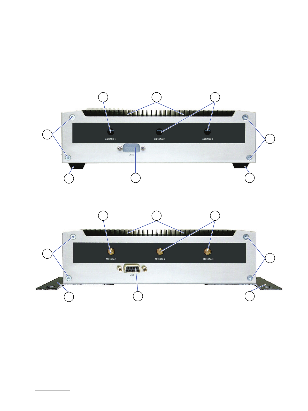
KBox A-103 – User Guide, Rev. 3.0
1 Covered cutout for the Reverse (RP) SMA connector of
5 Countersunk screws M3x8 ISO14581 torx
1
2
3
1
5
8
2 7 6 6 8 5 5
4.7.2. Rear Side View of the KBox A-103 as Desktop Unit or with Wallmount Bracket
Depending on the ordered system configuration, the KBox A-103 (desktop unit or with horizontal/vertical wallmount
brackets) can be equipped with the WLAN option with 3 antennas and/or with the GPIO option (Figure 20). If no
options were ordered the location for the WLAN antennas and for the GPIO-port are corresponding covered as shown
in Figure 19, pos. 1 and pos. 4.
Figure 19: Rear side of the KBox A-103 without optional WLAN and GPIO (shown as desktop unit)
5
4
3
Figure 20: Rear side of the KBox A-103 with optional WLAN and GPIO (shown with vertical/horizontal mounting
brackets)
the WLAN antennas (mPCIe WLAN card with 3
antennas is an option)
2 Cooling fins on the top side of the chassis
3 Rubber feet
4 Not installed GPIO interface (option)
6 Wall/table mount brackets with key holes (left and
right) for horizontal or vertical (with interface sides
downwards or upwards) mounting position
7 Installed GPIO option
8 Reverse (RP) SMA connectors for the WLAN
antennas
www.kontron.com // 32
Page 33
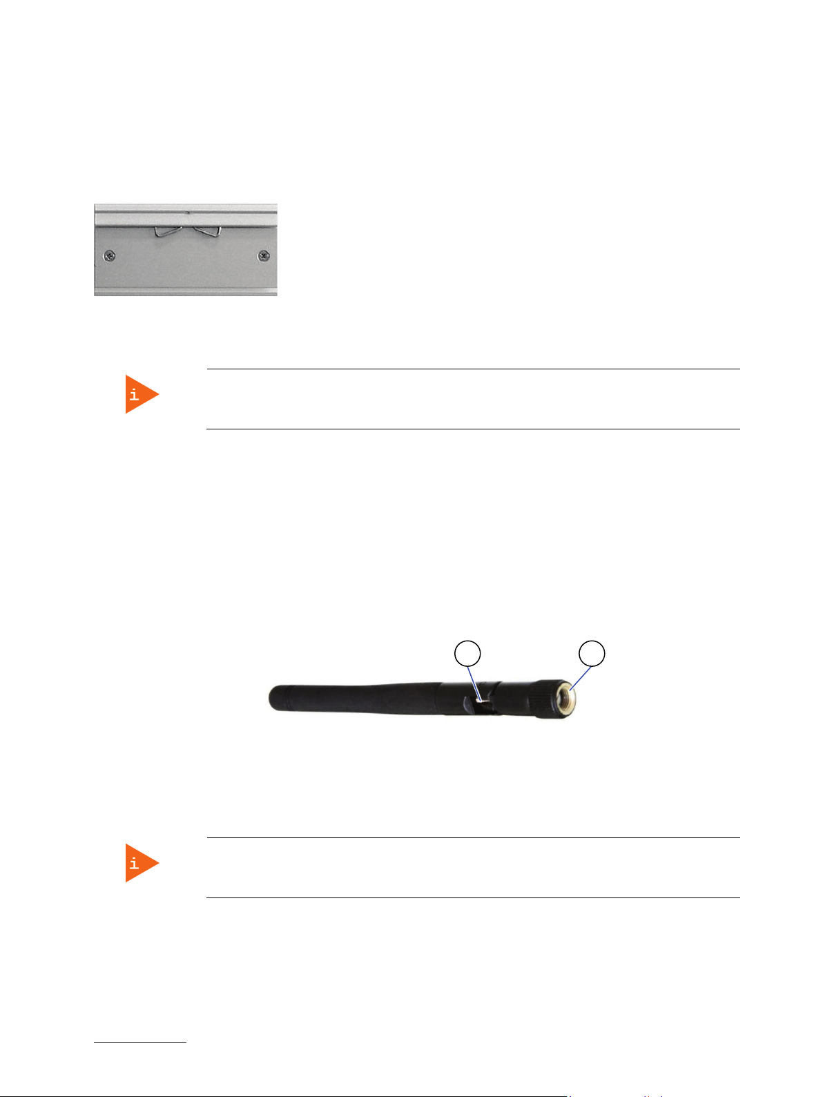
KBox A-103 – User Guide, Rev. 3.0
I
2
1
4.7.3. DIN Rail Clip (Option)
For DIN Rail mounting of the KBox A-103, may be ordered a DIN Rail clip (refer to subsection 3.2.2 “Optional Parts”).
If ordered, you can adopt your system for mounting to a DIN Rail. On the vertical mounting plate (Figure 18, pos. 4) and
on the access cover (Figure 14, pos. 8) are provided tapped holes for mounting the optional DIN Rail clip (Figure 21).
Figure 21: DIN rail clip
4.7.4. WiFi/WLAN (Option)
Please observe that the KBox A-103 with vertical mounting plate (Figure 18) can’t be
Depending on the ordered system configuration, the KBox A-103 system (only KBox A-103 used as desktop or KBox A103 with vertical/horizontal wallmount brackets or with DIN Rail clip) can be equipped with WiFi hardware. If you
have ordered a system configuration including WLAN, at the rear side, two Reverse (RP) SMA-connectors (Figure 20,
pos.8) for screwing on the provided WLAN antenna are installed.
extended with the WLAN option.
4.7.4.1. WLAN/WiFi Antenna
During the installation of the KBox A-103 the provided system antennas (Figure 22) will be screwed onto the
RP SMA connectors (Figure 20, pos.8) of the system. The antennas may be tilted and rotated in the appropriate
positions to get the optimal transmission and reception quality.
Figure 22: WLAN (WiFi) antenna
1 Reverse (RP) SMA antenna connector
2 Hinge for positioning the antenna
4.7.5. GPIO Interface (Option)
The KBox A-103 with vertical mounting plate (Figure 18) can’t be extended with the GPIO
Optionally, the KBox A-103 may be equipped with via an internal factory mounted GPIO adapter (General Purpose
nput/Output) interface. Peripheral devices can be controlled freely programmable via this interface, which consists
of a 9-pin D-SUB connector interface (Figure 20, pos. 7). The GPIOs can be controlled via the KEAPI (Kontron
Embedded API), which is part of the official Board Support Package.
option.
www.kontron.com // 33
Page 34

4.8. Internal View
20 2113 9 14
16
11
15
10
Figure 23: KBox A-103 - internal view (without cover)
1
22
19
18
17
4 3
KBox A-103 – User Guide, Rev. 3.0
6 2
5 7 8
1 Rear Panel
2 Tapped holes for cover mounting (8x)
3 Jumper J46 to configure COM 3
4 BIOS recovery jumper J49 (default setting is OFF)
5 Onboard header (J44) for COM 3 (X206) serial port
(configurable as RS422/RS485 by jumper J46)
6 SIM card socket
7 Onboard VGA header (J52)
8 Onboard header for optional lithium battery
9 Gold cap (for RTC)
10 Baseboard of the KBox A-103
12
12 Screws that secure the mPCIe card for PROFIBUS
13 Interface side
14 RS422/RS485 adapter module (COM 2)
15 DIP switch of the RS422/RS485 (COM 2) adapter
module
16 mPCIe slot (J37 onboard)
17 mSATA slot (J17 onboard)
18 Screws that secure the mSATA SSD
19 Connector for power cable of the 2.5" SSD/HDD
20 Connector for data cable of the 2.5" SSD/HDD
21 Onboard header (J34) for GPIO port
11 mPCIe card with heat sink of the PROFIBUS card
(always only factory installed into J27 onboard
mPCIe slot)
22 Onboard header (J42) for COM 2 serial port
(configurable as RS232 by cable or RS422/RS485 via
adapter card; in Figure 23 shown with connection to
the installed adapter card)
www.kontron.com // 34
Page 35

KBox A-103 – User Guide, Rev. 3.0
The KBox A-103 provides two internal mPCIe slots (J27 and J37). The onboard slot J27 is used
for installation of the the mPCIe card for PROFIBUS (Figure 23, pos. 11). This PCIe slot J27 of
the baseboard can be fitted only at the factory with a PROFIBUS expansion card.
4.8.1. Integrated SMARC-sXBTi Module
Your KBox A-103 accommodates a baseboard with an SMARC-sXBTi module. It is located on the bottom side of the
baseboard and is not accessible for the user.
Refer to the information and technical data in the user manual of the installed SMARC-sXBTi
module.
The user’s manual of the installed SMARC-sXBTi can be downloaded from our web page
www.kontron.com . Search for the name of the installed board.
4.8.2. SATA Interface
Depending on the system configuration ordered your KBox A-103 can be extended with a 2.5" SATA SSD. It is located
on the inside of the access cover (refer Figure 25 pos. 4).
4.8.3. mSATA Socket
Depending on the system configuration ordered your KBox A-103 can be extended with an mSATA SSD.
For installation/removing of the mSATA SSD, refer to the subsection 5.1.6, “Installing an mSATA SSD”.
4.8.4. Expansion Slots for mPCIe Cards
Depending on the system configuration ordered your KBox A-103 can be extended with up to two mPCIe cards.
The KBox A-103 provides two internal mPCIe slots (J27 and J37). The J27 slot is used for
installation of the the mPCIe card for PROFIBUS (Figure 23, pos. 8) and can be only at the
factory fitted with aPROFIBUS expansion card.
For installation of an mPCIe card into an mPCIe slot please refer to the subsection 5.1.5 “Installing an mPCIe Mini Card“.
The J37 slot (Figure 23, pos. 16) can be used for the installation of a mPCIe WLAN card or an
mPCIe modem adapter card (which uses the onboard SIM card reader socket).
If an mPCIe WLAN card is installed into your KBox A-103, the SIM card slot is not functional.
4.8.4.1. SIM Card
The baseboard of the KBox A-103 is equipped with a SIM card socket (Figure 23, pos. 6).
To avoid damage to the SIM card, insert the SIM card before you turn the power on and
www.kontron.com // 35
remove the SIM card after you turn the power off.
Page 36

KBox A-103 – User Guide, Rev. 3.0
Before installing/removing an add-on card, please pay attention to the following information:
5/ Accessing internal Components
This section contains important information that you must read before accessing the internal components. You must
follow these procedures properly when installing, removing or handling any board.
It is recommended to expand your system with additional mPCIe Mini cards before it is installed into an industrial
control cabinet. Please consider following instruction when you install (or remove) expansion cards.
Please observe the “General Safety Instructions for IT-Equipment” provided with the system
(refer to the chapter 1/) and the installation instructions in this manual.
Only personnel with appropriate qualifications, trainings and authorization are permitted to
install and work with the KBox A-103.
The installation/removal of SSD and/or expansion cards may only be performed by a
qualified person, according to the description in this manual.
Before removing the cover of the device, make sure that the device is turned off and
disconnected from the power supply.
Before you upgrade the KBox A-103 with add-on cards, pay attention to the power
specifications in chapter 10/ “Technical Specifications
consumption of the add-on cards does not exceed 5 W per card.
” and make sure that the power
Please follow the safety instructions for components that are sensitive to electrostatic
discharge (ESD). Failure to observe this warning notice may result in damage to the device or
the latter’s components.
Please pay attention to the manufacturer’s instructions before installing/removing an addon card.
www.kontron.com // 36
Page 37
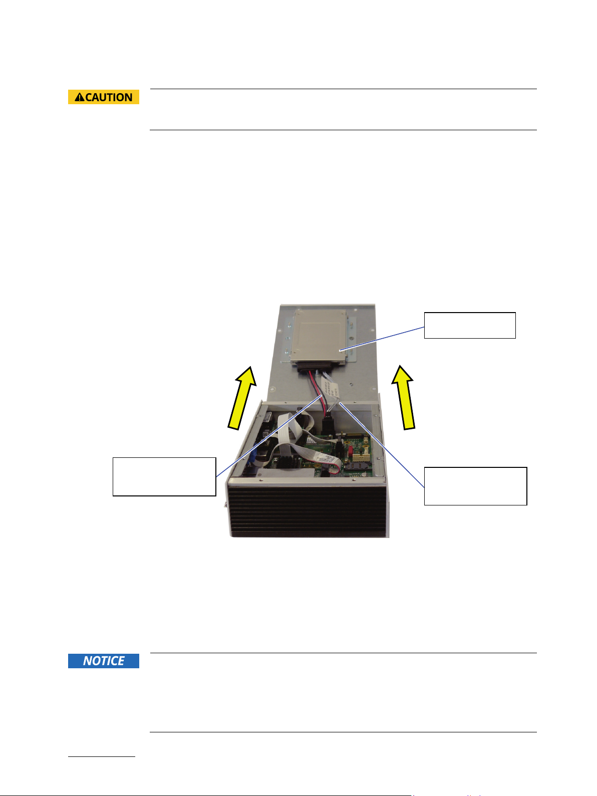
KBox A-103 – User Guide, Rev. 3.0
Power cable of the
Installed 2.5" SSD
5.1. Opening and Closing the KBox A-103
Before opening the KBox A-103, the system must be switched off and disconnected from the
main power supply. Also, disconnect all peripheral devices from the KBox A-103. Before you
begin, ensure that you have a clean, flat and ESD-safe surface to work on.
For opening and closing the KBox A-103, please perform the following steps:
1. Close all applications. Shut down the system properly and disconnect the connection to the main power source.
Disconnect all peripherals.
2. The KBox A-103 should lay on a flat, clean surface with the access cover (Figure 14, pos. 6) facing upwards.
3. Loosen and remove the eight torx screws (Figure 14, pos. 2), that secure the access cover to the chassis. Retain
the screws for later use.
4. Lift the access cover up as shown in the picture below (Figure 24). In order to remove the access cover you have
to disconnect the cables of the SSD drive and of the optional lithium battery, if available (refer to Figure 25, pos. 2,
pos. 10 and pos. 11).
Figure 24: Opening the access cover of the KBox A-103
5. Now you have access to the internal SIM, mPCIe and mSATA slots or cards, respectively SSD in order to remove or
6. For closing replace carefully power and data cables of the SSD (if installed) and the access cover to the system
7. Tighten the retained screws when the cover is firmly in place.
www.kontron.com // 37
installed 2.5" SSD
Data cable of the
installed 2.5" SSD
install hardware components. Also you can configure according to your requirements the serial ports COM 2
(X204) and COM 3 (X206).
and screw it on with the retained screws.
When used as intended, the KBox A-103 is to operate only in closed condition.
Only when the access cover (Figure 25) is properly fixed with the screws (Figure 14, pos. 2)
and the rear side with GPIO-port and/or WLAN antennas (available on KBox A-103 as
desktop unit or equipped with horizontal/vertical wallmount brackets, refer to Figure 19 and
Figure 20) are properly installed and secured with the screws (Figure 19 and Figure 20, pos.
5), it is ensured that the user does not have access to the internal parts of the KBox A-103.
Page 38

KBox A-103 – User Guide, Rev. 3.0
1 Inside of the top cover
7 Countersunk screws M3x8 ISO14581 torx for
11
5 6 5 7 5 5 8
8 9 10
5.1.1. Access Cover
The cover (Figure 14, Fig. 6) of the KBox A-103 is the access side of the internal components.
Figure 25: Inside of the access cover
4
3
2
1
2 Power connector for 2.5" SSD drive
3 Holes for assembling the cover to the chassis
(8x)
4 2.5" SSD drive
5 Screws that secure the 2.5" SSD to the drive
mounting brackets
6 Mounting brackets for fixing the 2.5" SSD drive to
the internal side of the KBox A-103 cover
assembling the drive mounting brackets to the
cover
8 Threaded holes for mounting the DIN rail
mounting clip
9 Optional lithium battery
10 Connector of the optional lithium battery
11 Connector of the data cable of the 2.5" SSD drive
www.kontron.com // 38
Page 39

KBox A-103 – User Guide, Rev. 3.0
DIP Switches (DIP1-DIP3)
DIP Switches (DIP4-DIP8)
5.1.2. Serial Port COM2 (X204) Configuration for RS422 or RS485 via DIP Switches
The serial port COM 2 is connected to J42 on the motherboard. It can be configured for RS232 (without any
configuration) or for RS422 or RS485 serial communication (with an external module at the rear side of the COM
connector) via an on-board DIP switch (SW1). For pin assignment refer to subsection 11.1.7 to 11.1.10.
In order to change the factory configuration of the RS422/RS485 port [factory settings: refer to the grey highlighted
settings of the SW1 (DIP1-DIP8) (Figure 27, Table 1, Table 2 and Table 3)] proceed as follows:
The new port configuration has to be set before the system is installed onto a table, wall or
into an industrial cabinet. The system must be disconnected from the power source.
Disconnect all peripherals. Before you begin, ensure that you have a clean, flat and ESD-safe
surface to work on.
1. Open the KBox A-103 as described in the section 5.1 “Opening and Closing the KBox A-103”, steps 1 to 4.
2. Locate the DIP switches in the unit (refer to Figure 23, pos. 15 and Figure 26).
3. By use of an insulated thin tool (e. g. screwdriver or a stylus) set the DIP switches to the up (for ON) or down (for
OFF) position corresponding the needed port configuration; refer to (Figure 27, Table 1, Table 2 and Table 3).
Figure 26: DIP1-DIP8 switches (shown with factory settings)
in OFF position (factory
settings)
in ON position (factory
settings)
The optional settings (SW1) for RS485 mode communication allow the system’s operation either in full duplex mode
or in half duplex mode (see tables on the next page). While running in RS485 half-duplex mode the system stays
permanently in a receiver mode. The switch to transmission mode will be done automatically. The user can determine
if the automatic mode switch to transmission mode should be triggered by the RTS-line or should be triggered by the
last sent message using the TxD line.
If triggered by RTS has been selected, then the RTS-signal must be activated by the application software before
transmission of the data packets starts; and RTS signal has to be disabled again after termination of data
transmission.
If TxD line will be used for the mode transceiver switch process, the receiver device has to follow a timeout before
starting to send any data.
Figure 27: DIP-Switch (SW1) with DP1 to DP8 for RS422/RS485 serial communication settings (for COM 2)
www.kontron.com // 39
Page 40

KBox A-103 – User Guide, Rev. 3.0
RS422 4-Channel Mode
-
OFF
OFF
OFF
Activated
ON
0.6ms
19200
ON
ON
ON
ON
In order to configure this external interface for serial communication (as RS422 or RS485) corresponding to your
requirements, set the switches of the DIP switch (SW1) to “ON” or “OFF” (factory settings are in bold letters). For
accessing the DIP switch refer to the procedure described in the chapter 5.1 “Opening and Closing the KBox A-103”.
Table 1: DIP1, DIP2 and DIP3 settings for serial communication type
X204: Serial Communication Type Transmitting<->receiving SW1 Settings
DIP1 DIP2 DIP3
RS485 4-Wire Mode (Bus-Master) - ON OFF ON
RS485 2-Wire Mode RTS ON ON ON
RS485 2-Wire Mode Timeout ON ON OFF
Table 2: DIP4 setting in order to activate or deactivate the termination resistor
Termination Resistor for RS422 and RS485 SW1 Settings
DIP4
Deactivated OFF
Table 3: DIP5, DIP6, DIP7 and DIP8 settings in order to set the needed Timeout and min. baud rate
Timeout Min. Baud Rate SW1 Settings
DIP5 DIP6 DIP7 DIP8
10.2ms 1200 OFF OFF OFF OFF
9.6ms OFF OFF OFF ON
9.0ms OFF OFF ON OFF
8.4ms OFF OFF ON ON
7.8ms OFF ON OFF OFF
7.2ms OFF ON OFF ON
6.5ms OFF ON ON OFF
5.9ms OFF ON ON ON
4.8ms 2400 ON OFF OFF OFF
4.3ms ON OFF OFF ON
3.7ms ON OFF ON OFF
3.1ms ON OFF ON ON
2.5ms 4800 ON ON OFF OFF
1.9ms ON ON OFF ON
1.2ms 9600 ON ON ON OFF
4. Replace carefully power and data cables of the SSD (if installed) and the access cover to the system and screw it
on with the retained screws.
5. Tighten the retained screws when the cover is firmly in place.
www.kontron.com // 40
Page 41

KBox A-103 – User Guide, Rev. 3.0
OPEN
CLOSE
CLOSE
RS485 full duplex
CLOSE
Pin 1: TxDPin 3: RxD+
Pin 5: TxD+
Pin 7: RxD-
Refer to pin assignment:
11.1.11
RS422 full duplex
CLOSE
Pin 1: TxDPin 2: RTSPin 3: RxD+
Pin 4: RTS+
Pin 5: TxD+
Pin 6: CTS+
Pin 7: RxDPin 8: CTS-
Refer to pin assignment:
11.1.13
5.1.3. Serial Port COM 3 (X206) Configuration of the Serial Port COM 3
In order to configure the serial port COM3 as RS422 or RS485, there are following options to set the jumper J46
(Figure 23, pos. 3):
: RS485 half duplex (2 wires)
: RS485 full duplex (4 wires) or
: RS422 full duplex (8 wires) depends on user cabling connection to X206
Table 4: J46 settings forCOM 3 RS485 and RS422 modes (factory settings are in bold letters)
Communication Mode
Jumper J46 J44, onboard Header or COM 3 X206: DSUB (9-pin female)
COM 3 (X206)
RS485 half duplex OPEN Pin 1: TxD-/RxD-
Pin 5: TxD+/RxD+
In the “Advanced Kontron Board RS422/485 DUPLEX Mode” menu of the BIOS setup,
“Half Duplex” or “Full Duplex” must be selected according to the selected communication
mode.
Refer to pin assignment:
11.1.12
www.kontron.com // 41
Page 42

KBox A-103 – User Guide, Rev. 3.0
5.1.4. Optional GPIO Port
The optional GPIO port (Figure 20, pos. 7) on the rear side of the KBox A-103 is connected to J34 on the motherboard
(Figure 23, pos. 21):
Table 5: Pin assignments of internal and external GPIO connector
J34, onboard GPIO Header GPIO Port: DSUB Connector (9-pin female)
Pin 1: V_3V3_GPIO_OUT --
Pin 2: GND Pin 1
Pin 3: GPIO_0_3V3 Pin 6
Pin 4: GPIO_1_3V3 Pin 2
Pin 5: GPIO_2_3V3 Pin 7
Pin 6: GPIO_3_3V3 Pin 3
Pin 7: GPIO_4_3V3 Pin 8
Pin 8: GPIO_5_3V3 Pin 4
Pin 9: GPIO_6_3V3 Pin 9
Pin 10: GPIO_7_3V3 Pin 5
Pin 11: GND --
Pin 12: V_5V0_GPIO_OUT --
5.1.5. Installing an mPCIe Mini Card
To have access to the mPCIe slot (Figure 23, pos. 16) please proceed according to the steps described:
1. Open the device as described in the subsection 5.1 “Opening and Closing the KBox A-103” (step 1-4).
2. Locate the mPCIe card slot and the corresponding fixing bolts (Figure 23, pos. 16).
3. Align the notches on the mPCIe card with the notches in the mPCIe socket (J27 or J37). Insert the mPCIe card into
the slot (Figure 23, pos. 16) and rotate it down with the fixing holes of the card over the fixing bolts.
4. Press the mPCIe card down on the side with the fixing holes and secure it with the available fastening screws.
5. In order to close the KBox A-103, proceed in reverse order.
To install an mPCIe card into the mPCIe slot (Figure 23, pos. 16), if your KBox A-103 is
equipped with an RS422/RS485 adapter module, you have to remove the RS422/RS485
adapter module (Figure 23, pos. 14), by unscrewing the two fastening screws of the DSUB
connector COM 2 (X204, Figure 10)on the front side of the system. Retain the screws for
later use.
Replace the RS422/RS 485 adapter module, after the installation of the mPCIe card, by
screwing on the DSUB connector COM 2 to the front side with the retained screws.
www.kontron.com // 42
Page 43

KBox A-103 – User Guide, Rev. 3.0
5.1.6. Installing an mSATA SSD
To have access to the mSATA slots please proceed according to the steps described:
1. Open the device as described in the subsection 5.1 “Opening and Closing the KBox A-103” (step 1-4).
2. Locate the mSATA slot (J17) (Figure 23, pos. 17) and the corresponding fixing bolts. (Figure 23, pos. 18).
3. Align the notches on the mSATA SSD with the notches in the mSATA slot (J17). Insert the mSATA SSD into the
corresponding slot (Figure 23, pos. 17) and rotate it down with the fixing holes of the card over the fixing bolts.
4. Press the mSATA SSD down on the side with the fixing holes and secure it with the available fastening screws
(Figure 23, pos. 18).
5. In order to close the KBox A-103, proceed in reverse order.
5.1.7. Installing the SIM Card
1. Open the device as described in the subsection 5.1 “Opening and Closing the KBox A-103” (step 1-4).
2. Locate SIM card socket (Figure 23, pos. 6).
3. To unlock the SIM card socket slide the cover of the SIM socket towards inside of the device (see arrows in Figure
28).
4. Lift gently the slot cover and open the slot cover as shown in Figure 29.
5. Slide the SIM card (Figure 30) into the left and right card guides of the socket cover and push down the cover in
order to close the cover (refer to Figure 31).
6. After closing the cover, lock the cover by sliding the closed cover in the direction shown in Figure 32.
Figure 28: Locked SIM card socket (without
SIM card)
Figure 31: Inserted SIM card into the card
holder of the SIM socket
Figure 29: Unlocked and opened SIM card
socket
Figure 32: Closed and locked SIM card socket
with inserted SIM card
Figure 30: Mini SIM
card
www.kontron.com // 43
Page 44

KBox A-103 – User Guide, Rev. 3.0
5.1.8. BIOS Recovery Jumper
The BIOS recovery jumper is located on the motherboard (Figure 23, pos. 4). If the BIOS is corrupt and the KBox A-103
cannot be booted (e.g. by a power failure while saving the BIOS settings), the system can be booted via a recovery
BIOS. The default setting of J49 is OPEN (Figure 33, left image). After J49 has been set to CLOSED (Figure 33, right
image), the system can be booted from the recovery BIOS. For further information, contact Kontron support.
Figure 33: J49 in open (default) and closed position
5.1.9. Replacing the optional Lithium Battery
To replace the optional lithium battery (Figure 25, pos. 9) please proceed according to the steps described:
1. Open the KBox A-103 as described in the section 5.1 “Opening and Closing the KBox A-103”, steps 1 to 4.
2. Remove the old lithium battery from the battery clip.
3. Attach new lithium battery to the battery clip.
4. In order to close the KBox A-103, proceed in reverse order.
www.kontron.com // 44
Page 45

KBox A-103 – User Guide, Rev. 3.0
6/ Thermal Considerations
6.1. Available Processors
Please refer to the chapter 10/ “Technical Specifications”.
The list of processors is not complete and may be extended over the product lifetime.
6.2. Convection Cooling
The applied cooling method provides adequate cooling of the device during operation and performs a one-way
thermal transfer to the chassis. Three sides of the KBox A-103 consist of a compact aluminum U-shaped chassis are
with cooling fins. The cooling fins provide heat dissipation during operation.
To provide sufficient heat dissipation for the cooling of the KBox A-103, never cover the
6.3. Minimum System Clearance
cooling fins of the chassis. Do not place any objects on the device.
To provide a maximum of airflow through and around the box, minimum distances to surrounding parts must be
observed (please refer to the chapter 7.1 “System Mounting” and Figure 34).
6.4. Maximum Temperatures
The maximum system ambient temperature depends mostly on the power consumption of
For the temperature evaluation a specialised tool from Intel
Depending on the power consumption one or more cores were set to 75% workload. This includes the graphics core.
The tool also handles the usage of the "Turbo Mode" of certain processor types.
the processor and the chipset.
®
was used to set the processor to a defined workload.
The processor utilisation depends highly on the software used. Software using multicore
feature will run on several cores whereas standard software will only utilise one core. In
this case the processor will use the "Turbo Mode" to increase the clock for the core with the
highest workload, as long as the temperature is within limits.
6.5. Third Party Components
When the KBox A-103 is extended and configured with third party components like mPCIe extension cards and hard
drives (HDD or SSD), it has to be taken into account that the air temperature inside the system is higher than the
ambient temperature. An approximately internal temperature rise is given for assistance.
www.kontron.com // 45
Page 46

KBox A-103 – User Guide, Rev. 3.0
7/ Installation Instructions
The KBox A-103 system is designed for operating:
within control cabinets by use of the vertical mounting plate and/or DIN Rail mounting clip
installed onto a wall or table by use of the corresponding vertical/horizontal wallmount brackets
as desktop unit (horizontal position), by attaching the supplied self-adhesive feet.
Expansion card installation should be performed before installing the KBox A-103 into the
control cabinet, onto a table or wall.
Whenever possible, unpack or pack this product only at EOS/ESD safe work stations. Where
a safe work station is not guaranteed, it is important for the user to be electrically
discharged before touching the product with his/her hands or tools. This is most easily done
by touching a metal part of the system chassis.
Do not handle this product out of its protective enclosure while it is not used for operational
purposes unless it is otherwise protected.
Prior any installation work, ensure that there are no live wires on the installation site.
Do not handle the device if there is any damage visible.
Do not operate the KBox A-103 with foreign objects inside the chassis.
Further do not insert any retrieval device into the device while it is connected to power.
Kontron rejects all liability for any and all damages resulting from operation of the unit with
foreign objects inside the chassis.
The KBox A-103 has to be installed and operated only by trained and qualified personnel.
Only personnel with appropriate qualifications, trainings and authorization are permitted to
install and work with the Kontron KBox A-103.
This device shall only be installed in or connected to systems that fulfill all necessary
technical and specific environmental requirements.
The unit must be placed such that there is sufficient space in front of it for connecting the
cables to the
I/O interface connectors and for operating the power button.
Leave sufficient free space around the unit to prevent the device from possibly overheating!
To ensure proper operation, we recommended free space as specified in Figure 34 and
Figure 35.
Refer also to section 10.1.2 “Mechanical Specifications”.
The KBox A-103 must be firmly attached to a clean flat and solid mounting surface. Use
proper fastening materials suitable for the mounting surface. Ensure that the mounting
surface type and the used mounting solution safely support the load of the KBox A-103 and
the attached components.
Please follow the local/national regulations for grounding.
The voltage feeds must not be overloaded. Adjust the cabling and the overcurrent protection
to correspond with the electrical figures indicated on the type label.
The type label is located on the access cover of the system.
It is recommended that the last cable attached to the system should be the power cable!
Refer to the section 7.2 “DC Power Connection” and chapter 8/ “Starting Up”.
www.kontron.com // 46
Page 47

KBox A-103 – User Guide, Rev. 3.0
7.1. System Mounting
In order to adapt the KBox A-103 for mounting Kontron offers different mounting solution such as:
KBox A-103 configuration with vertical mounting plate for installation into a control cabinet or
KBox A-103 configuration with wall/table mounting brackets for vertical or horizontal mounting position
KBox A-103 as desktop unit (equipped with the supplied rubber feet)
KBox A-103 for DIN Rail mounting
Depending on the ordered KBox A-103 configuration, your system is supplied with the corresponding mounting plate,
mounting brackets and/or DIN Rail clip.
The key holes of the vertical mounting plate (Figure 18, pos. 2) allow you to mount the KBox A-103 inside the control
cabinet in vertical position.
The key holes of the mounting brackets (Figure 20, pos. 6) allow you to mount the KBox A-103 to a wall or table in
vertical as well as in horizontal position.
Prepare the mounting surface with four screws and if necessary anchors corresponding to the mounting surface type
(fire-resistant material). Please refer to the information for mounting in the section 10.1.2, “Mechanical Specifications
of the KBox A-103 with Vertical Mounting Plate”, 10.1.3 “Mechanical Specifications of the KBox A-103 Wall/Table
Mounting Brackets”, 10.1.1 “Mechanical Specifications of the KBox A-103 as Desktop” or refer to the drawings for KBox
A-103 on our web site. The drawings can be downloaded from our web site www.kontron.com
product name.
For a sufficient air circulation around the device, we recommend not mount or operate any
other devices within the “Restricted Area” around the KBox A-103; refer to the red marked
area in Figure 34, Figure 35.
by selecting the
Figure 34: Restricted area for mounting around KBox A-103 (desktop side view with antenna)
Figure 35: Restricted area for mounting around KBox A-103 (front view with vert./horiz. mounting brakets)
www.kontron.com // 47
Page 48

KBox A-103 – User Guide, Rev. 3.0
1 3-pin Phoenix plug terminal
4 Location for inserting the “0V” wire
4
3
7.2. DC Power Connection
The KBox A-103 is connected by a Phoenix connector to a DC power source via a DC power supply wiring (only the
Phoenix power plug terminal is included).
The KBox A-103 is delivered with a DC power plug terminal (3-pin Phoenix connector). For DC connection, prepare the
connecting wires using the supplied Phoenix plug terminal: PSC 1,5/ 3-F.
Figure 36: Phoenix power plug terminal
2 Cover over the slotted pan head screws
3 Location for inserting the functional earth wire
1 2
5
5 Location for inserting the “24V” wire
7.2.1. Cabling
For the pin assignment Phoenix power plug terminal refer to the subsection 4.4.1 “X101 - Power Input Connector”.
1. Cut the required length three isolated wires (1 mm2) AWG18 and strip each end 5 –7 mm.
2. Twist the striped wire-ends and provide them with ferrules.
3. Open the cover (Figure 36, pos. 2) to have access to the slotted pan head screws.
4. Loosen the three slotted pan head screws of the DC plug terminal far enough so that you can insert the end of
the prepared wires.
5. Insert the wires into the corresponding clamp of the Phoenix plug terminal. Make sure that you have the right
polarity of the connection [refer to Figure 36, Figure 11 or subsection 11.1.1, “(X101) Power Input Connector”].
6. Fasten the screws to secure the wires into the clamps of the plug terminal.
7. Close the cover (Figure 36, pos. 2).
www.kontron.com // 48
Page 49

KBox A-103 – User Guide, Rev. 3.0
8/ Starting Up
The KBox A-103 must be only operated with the nominal voltage of 24V DC of type SELV. For
8.1. Connecting to DC Main Power Supply
The DC input connector (Figure 10 and Figure 11 marked X101) is located on the front side of the KBox A-103. The KBox
A-103 will be connected to a DC main power supply via the supplied Phoenix power plug terminal (see Figure 36) and
corresponding power wires (not included).
details refer to the chapter 10/ “Technical Specifications”.
Before using your system, become familiar with the system components and check that
everything is connected properly. Following a proper cabling procedure will prevent a false
power-on condition, which could result in unit operational failure.
When you install/disconnect the unit, the functional earth connection must always be made
first and disconnected last.
Also, it is recommended that the last connections attached to the system should be the
power wires!
The KBox A-103 must be connected DC mains power supply complying with the SELV (Safety
Extra Low Voltage) requirements of EN 60950-1 standard.
It must be observed that wiring and short-circuit/overcurrent protection is performed
according to the applicable standards, regulations and respect to the electrical specification
of the KBox A-103.
Even when the system is turned off via the power button (Figure 10 and Figure 12, marked
PWR) parts of the system are still energized.
The disconnecting device (fuse/circuit backer) rating must be in accordance with the wire
cross-section and the rated current of the KBox A-103.
The wires used for power connections must be clearly marked (+/-/functional earth) to
ensure that they will be proper connected to the DC IN connector of the KBox A-103 and to
the main power source, corresponding to signals marked. Refer to Figure 11 and Figure 36.
To connect the KBox A-103 to a corresponding DC main power supply, please perform the following steps:
1. Ensure that the DC power source is switched off via a disconnecting device (circuit breaker), in order to ensure
that no power is flowing from the external DC power source during the connection procedure.
2. Connect at first the wire for “Functional Earth stud” (Figure 18, pos. 5) to an appropriate “common earth”
connection point.
In addition, the cables must have some form of support so as to minimize the strain on the
unit’s connectors.
3. Connect the Phoenix power terminal prepared as described in the subsection 7.2.1 “Cabling” to the DC input
connector (Figure 10 and Figure 11 marked X101) of the KBox A-103. The DC input connector is located on the front
side and is marked “24VDC”.
4. Connect the other ends of the DC power wires to the connections of the DC main power supply. Pay attention to
the polarity of the connections.
5. Switch on the disconnecting device (circuit breaker) in order to apply voltage to the terminals of the power wires.
www.kontron.com // 49
Page 50

KBox A-103 – User Guide, Rev. 3.0
8.2. Operating System and Hardware Component Drivers
Your system can be supplied optionally with a pre-installed operating system.
If you have ordered your KBox A-103 with a pre-installed operating system, all drivers are installed in accordance
with the system configuration ordered (optional hardware components). Your system is fully operational when you
switch it on for the first time. Please pay attention to the following note.
Important information on the use of the pre-installed “WINDOWS 7 ULTIMATE FOR
EMBEDDED SYSTEMS” or “WINDOWS 7 PROFESSIONAL FOR EMBEDDED SYSTEMS“
operating systems:
The terms and conditions for the use of the pre-installed operating systems are specified in
If you have ordered The KBox A-103 without a pre-installed operating system, you will need to install the operating
system and the appropriate drivers for the system configuration you have ordered (optional hardware components)
yourself.
the document “MICROSOFT SOFTWARE LICENSE TERMS”.
You can download this document from our web site www.kontron.com by selecting Product/
Downloads tab/Windows.
You can download the relevant drivers for the installed hardware from our web site at
www.kontron.com by selecting the product.
Pay attention to the manufacturer specifications of the operating system and the integrated
hardware components.
Latest Linux Distribution and Kernel shall be used in order to properly support the Baytrail
graphics engine.
E.g. for Ubuntu: Ubuntu 16.04.2 Release (Linux Kernel 4.8.xx) works with display connected
to DP.
www.kontron.com // 50
Page 51

KBox A-103 – User Guide, Rev. 3.0
9/ Maintenance and Cleaning
Equipment from Kontron requires only minimum servicing and maintenance for proper operation.
For light soiling, clean the KBox A-103 with a dry cloth.
Carefully remove dust from the surface of the cooling fins of the chassis using a clean, soft brush.
Stubborn dirt should be removed using a mild detergent and a soft cloth.
Do not use steel wool, metallic threads or solvents like abrasives, alcohol, acetone or
benzene for cleaning the KBox A-103.
www.kontron.com // 51
Page 52

KBox A-103 – User Guide, Rev. 3.0
10/ Technical Specifications
Table 6: Technical Specifications
KBox A-103
Installed Module and
Baseboard
SMARC Module Intel® Atom™ E3845, 4x 1.91 GHz, 4GB DDR3L with ECC, 16GB eMMC
RAM up to 8 GB DDR3L, with ECC soldered on SMARC module
BIOS Phoenix® BIOS
Interfaces
(front side accessible)
Internal Drive Bay
(not accessible from the
outside)
Option for Storage Media 1x mSATA socket
Free Expansions Slots
(internal)
Controls
(at the front side)
Indicators
(at the front side)
DC IN Connector (at the front
side)
Protection Class IP20
Rated Voltage (tolerance) 24 VDC (+20%/-15%)
Baseboard with SMARC-sXBTi module
Intel® Atom™ E3827 2x 1.75GHz, 2GB DDR3L
Intel® Atom™ E3815 1x 1.46GHz, 1GB DDR3L
2x Ethernet (10/100/1000 Mbit/s) with IEEE1588 support
1x USB 3.0
2x USB 2.0
1x DisplayPort
1x COM 1 (RS232)
1x VGA
Optional:
1x FIELDBUS (PROFIBUS; the expansion has to be installed at the factory only)
1x COM 2 (configurable as RS232 or RS422/RS485 via adapter module)
1x COM 3 (configurable as RS422/RS485 via onboard jumper)
1x internal drive bay to install 1x 2.5” SATA SSD (SATA 3Gb/s)
2x mPCIe sockets for full-size mPCIe modules, one with SIM card socket
Power button (PWR)
PWR (Power LED)
HDD (SSD status LED)
3-pin DC input connector
www.kontron.com // 52
Page 53

10.1. Mechanical Specifications
Table 7: Mechanical Specifications
KBox A-103 – User Guide, Rev. 3.0
Dimensions KBox A-103 with
vertical mounting plate
Height 266 mm (10.47") 135.5 mm (5.33") 65.6 mm (2.58")
Width 58 mm (2.28") 270 mm (10.63") 210 mm (8.27")
Depth 138 mm (5.43") 65 mm (2.56") 140 mm (5.51")
Weight
(without packaging,
without expansions)
Chassis Cooling fins, black
Approx. 1.85 kg (4.08 lbs.) Approx. 2 kg (4.41 lbs.) Approx. 1.8 kg (3.97 lbs.)
Chassis: steel sheet, light grey (RAL 7035)
Side with External Interfaces : trim strips, traffic grey (RAL 7043)
KBox A-103 with
vert./horiz. mounting
brackets
KBox A-103
as desktop
10.1.1. Mechanical Specifications of the KBox A-103 as Desktop
Figure 37: Dimensions: Front as desktop
Figure 38: Dimensions: Front side with antennas and wall/table mounting brackets
www.kontron.com // 53
Page 54

KBox A-103 – User Guide, Rev. 3.0
10.1.2. Mechanical Specifications of the KBox A-103 with Vertical Mounting Plate
Figure 39: Dimensions: Left side Figure 40: Dimensions: Rear side with vertical
mounting plate
Figure 41: Dimensions: Detail key hole
www.kontron.com // 54
Page 55

KBox A-103 – User Guide, Rev. 3.0
10.1.3. Mechanical Specifications of the KBox A-103 Wall/Table Mounting Brackets
Figure 42: Dimensions: Top side (with wall/table mounting brackets)
Figure 43: Dimensions: front side (with wall/table mounting brackets)
Figure 44: Detail mounting slide hole (wall/table mounting brackets)
www.kontron.com // 55
Page 56

KBox A-103 – User Guide, Rev. 3.0
10.2. Environmental Specifications
Table 8: Environmental Specifications
KBox A-103 (Standard Version)
Thermal Management Fanless cooling
Operating Temperature -20°C … +60°C (-4 … 140°F)
Storage / Transit Temperature -40°C … +85°C (-40°F … +185°F)
Relative Humidity (Operating/Transit) 95 % @ 40 °C (non-condensing) acc. to IEC 60068-2-78
Max. Operation Altitude 2,000 m (6,560 ft)
Max. Storage / Transit Altitude 10,000 m (32,810 ft)
Operating Shock 15 G, 11 ms, half sine, acc. to IEC 60068-2-27
Non-operating/Transit Shock 50 G, 11 ms, half sine (IEC 60068-2-27) no HDD and add on cards
Operating Vibration 10 - 150 Hz, 1 G (IEC 60068-2-6)
Non-operating/Transit Vibration 10 - 150 Hz, 2 G (IEC 60068-2-6)
www.kontron.com // 56
Page 57

KBox A-103 – User Guide, Rev. 3.0
10.3. CE Directives and Standards
Table 9: CE Directive
CE Directive
Electrical Safety General Product Safety Directive (GPSD) 2001/95/EC
Low Voltage Directive (LVD) 2014/35/EU
Electromagnetic Compatibility (EMC) EMC Directive 2014/30/EU
CE Marking CE Directive 93/68/EEC
RoHS II Directives 2011/65/EU
Table 10: Electrical Safety
Electrical Safety Harmonized Standards
EUROPE
U.S.A. / CANADA Conform UL 60950-1
CB Report IEC 60950-1(ed.2);am1, am2
Information technology equipment - Safety - Part 1: General
requirements
EN 60950-1:2006+A11:2009+A1:2010+A12:2011+A2:2013
Conform UL 61010-1 & 61010-2-201
Certified to CAN/CSA C22.2 No. 60950-1
Table 11: EMC
EMC Harmonized Standards
EU Generic standards - Emission standard for industrial environments
(Emission):
EN 55032, Class A
EN 61000-6-4
Generic standards - Immunity for industrial environments (Immunity):
EN 55024, EN 61000-6-2
www.kontron.com // 57
Page 58

11/ Standard Interfaces – Pin Assignments
Low-active signals are indicated by a minus sign.
11.1.1. (X101) Power Input Connector
Table 12: (X101) Power Input Connector
Pin Signal Name 3-pin POWER SUBCON (male)
1 0V (input
2 Ground
3 +24 VDC (input)
11.1.2. (X102 as ETH 1 and X103 as ETH 2) Ethernet Connectors
Table 13: (X102, X103) Ethernet Connectors
Pin Signal Name X2, X3, X10LAN1, LAN2,LAN3 (RJ45)
1 MDI0+
2 MDI0-
3 MDI1+
4 MDI2+
5 MDI2-
6 MDI1-
7 MDI3+
8 MDI3-
KBox A-103 – User Guide, Rev. 3.0
Speed (Mbps)
10 off on orange on (blinking)
100 green on orange on (blinking)
1000 orange on orange on (blinking)
www.kontron.com // 58
LINK ACTIVE
LINK/ACT
Page 59

KBox A-103 – User Guide, Rev. 3.0
11.1.3. (X105) USB 3.0 Port
Table 14: (X105) USB 3.0 Port
Pin Signal Name Pin Signal Name 9-pin USB Connector
USB 2.0 contact pins USB 3.0 contact pins
1 VCC, fused (900 mA max.) 5 StdA_SSRX-
2 Data- 6 StdA_SSRX+
3 Data+ 7 GND_DRAIN
4 GND 8 StdA_SSTX-
9 StdA_SSTX+
Type A Version 3.0/2.0
11.1.4. (X107, X108) USB 2.0 Port
Table 15: (X107, X108) USB 2.0 Port
Pin Signal Name 4-pin USB Connector Typ A Version 2.0
1 VCC
2 Data-
3 Data+
4 GND
11.1.5. (X109) DisplayPort
Table 16: (X109) DisplayPort
Pin Signal Name DisplayPort Signal Name Pin
1 ML Lane 0 (p)
3 ML Lane 0 (n) Lane 1 (p) 4
5 GND (ML Lane 1) Lane 1 (n) 6
7 Lane 2 (p) GND (ML Lane 2) 8
9 Lane 2 (n) Lane 3 (p) 10
11 GND (ML Lane 3) Lane 3 (n) 12
13 AUX SEL# Pull-down to GND 14
15 AUX CH (p) GND (AUX CH) 16
17 AUX CH (n) Hot Plug 18
19 GND (GND_DDC)
GND (ML Lane 0) 2
3.3V (DDC EEPROM
power
500 mA fused
20
www.kontron.com // 59
Page 60

11.1.6. (X110) Serial Interface COM 1 (RS232)
Table 17: (X110) Serial Interface COM 1 (RS232)
Pin Signal Name 9-pin D-SUB Connector (male)
1 DCD (Data Carrier Detect)
2 RXD (Receive Data)
3 TXD (Transmit Data)
4 DTR (Data Terminal Ready)
5 GND (Signal Ground)
6 DSR (Data Set Ready)
7 RTS (Request to Send)
8 CTS (Clear to Send)
9 RI (Ring Indicator)
11.1.7. (X204) Serial Interface COM 2 (RS232)
KBox A-103 – User Guide, Rev. 3.0
Table 18: (X204) Serial Interface COM 2 (RS232)
Pin Signal Name 9-pin D-SUB Connector (male)
1 DCD (Data Carrier Detect)
2 RXD (Receive Data)
3 TXD (Transmit Data)
4 DTR (Data Terminal Ready)
5 GND (Signal Ground)
6 DSR (Data Set Ready)
7 RTS (Request to Send)
8 CTS (Clear to Send)
9 RI Ring Indicator
www.kontron.com // 60
Page 61

KBox A-103 – User Guide, Rev. 3.0
11.1.8. (X204) Serial Port COM 2 (RS422/RS485) configured as RS485 (2-Wire Mode) S, half duplex
Refer to the subsections 4.4.8 “X204 - Serial Port COM 2 (Option)” and to 5.1.2 “Serial Port COM2 (X204) Configuration
for RS422 or RS485 via DIP Switches”, Table 1, Table 2 and Table 3.
Table 19: (X204) Serial Port COM 2 (RS422/RS485) configured as RS485 (2-Wire Mode) S, half duplex
Pin Signal Name 9-pin D-SUB Connector (female)
1 Data-
2 NC
3 Data+
4 NC
5 GND
6 NC
7 NC
8 NC
9 NC
11.1.9. (X204) Serial Port COM 2 (RS422/RS485) configured as RS485 (4-Wire Mode), full duplex, (Bus-Master)
Refer to the subsections 4.4.8 “X204 - Serial Port COM 2” and to 5.1.2 “Serial Port COM2 (X204) Configuration for
RS422 or RS485 via DIP Switches”, Table 1, Table 2 and Table 3.
Table 20: (X204) Serial Port COM 2 (RS422/RS485) configured as RS485 (4-Wire Mode), full duplex, Bus-Master
Pin Signal Name 9-pin D-SUB Connector (female)
1 TxD- (Transmit Data-)
2 RxD+ (Receive Data+)
3 TxD+ (Transmit Data+)
4 RxD- (Receive Data-)
5 GND (Signal Ground)
6 NC
7 NC
8 NC
9 NC
www.kontron.com // 61
Page 62

KBox A-103 – User Guide, Rev. 3.0
11.1.10. (X204) Serial Port COM 2 (RS422/RS485) configured as RS422 (4-Channel Mode)
Refer to the subsections 4.4.8 “X204 - Serial Port COM 2” and to 5.1.2 “Serial Port COM2 (X204) Configuration for
RS422 or RS485 via DIP Switches”, Table 1, Table 2 and Table 3.
Table 21: (X204) Serial Port COM 2 (RS422/RS485) configured as RS422 (4-Channel Mode)
Pin Signal Name 9-pin D-SUB Connector (female)
1 TxD- (Transmit Data-)
2 RxD+ (Receive Data+)
3 TxD+ (Transmit Data+)
4 RxD- (Receive Data-)
5 GND (Signal Ground)
6 RTS- (Request to Send-)
7 RTS+ (Request to Send+)
8 CTS+ (Clear to Send+)
9 CTS- (Clear to Send-)
www.kontron.com // 62
Page 63

KBox A-103 – User Guide, Rev. 3.0
11.1.11. (X206) Serial Port COM 3 (RS422/RS485) configured as RS485 (4-Wire Mode), full duplex, (Bus-Master)
Refer to the subsections 4.4.9 ”X206 - Serial Port COM 3, and 5.1.3 “Serial Port COM 3 (X206) Configuration of the
Serial Port COM 3”.
Table 22: (X204) Serial Port COM 2 (RS422/RS485) configured as RS485 (4-Wire Mode), full duplex, Bus-Master
Pin Signal Name 9-pin D-SUB Connector (female)
1 TxD- (Transmit Data-)
2 RxD+ (Receive Data+)
3 TxD+ (Transmit Data+)
4 RxD- (Receive Data-)
5 GND (Signal Ground)
6 NC
7 NC
8 NC
9 NC
11.1.12. (X206) Serial Port COM 3 (RS422/RS485) configured as RS485 (2-Wire Mode), half duplex
Refer to the subsections 4.4.9 ”X206 - Serial Port COM 3, and 5.1.3 “Serial Port COM 3 (X206) Configuration of the
Serial Port COM 3”.
Table 23: (X206) Serial Port COM 3 (RS422/RS485) configured as RS485 (2-Wire Mode), half duplex
Pin Signal Name 9-pin D-SUB Connector (female)
1 TxD-/RxD-
2 NC
3 TxD+/RxD+
4 NC
5 GND (Signal Ground)
6 NC
7 NC
8 NC
9 NC
www.kontron.com // 63
Page 64

KBox A-103 – User Guide, Rev. 3.0
11.1.13. (X206) Serial Port COM 3 (RS422/RS485) configured as RS422 (8-Channel Mode) full duplex
Refer to the subsections 4.4.9 ”X206 - Serial Port COM 3, and 5.1.3 “Serial Port COM 3 (X206) Configuration of the
Serial Port COM 3”.
Table 24: (X206) Serial Port COM 3 (RS422/RS485) configured as RS422 (8-Channel Mode) full duplex
Pin Signal Name 9-pin D-SUB Connector (female)
1 TxD- (Transmit Data-)
2 RxD+ (Receive Data+)
3 TxD+ (Transmit Data+)
4 RxD- (Receive Data-)
5 GND (Signal Ground)
6 RTS- (Request to Send-)
7 RTS+ (Request to Send+)
8 CTS+ (Clear to Send+)
9 CTS- (Clear to Send-)
11.1.14. (X207) VGA Port
Table 25: (X207) VGA Port
Pin Signal name 15 pin D-SUB Connector (female)
1 Analog red output
2 Analog green output
3 Analog blue output
4 NC
5-8 GND
9 +5 V (DDC)
10 GND
11 NC
12 SDA (DDC)
13 TTL HSync
14 TTL VSync
15 SCL (DDC)
www.kontron.com // 64
Page 65

KBox A-103 – User Guide, Rev. 3.0
Table
12/ uEFI BIOS
12.1. Starting the uEFI BIOS
The KBOX-A103 is provided with a Kontron-customized, pre-installed and configured version of Phoenix SecureCore
Tiano (SCT). It is based on the Unified Extensible Firmware Interface (uEFI) specification and the Intel® Platform
Innovation Framework for EFI. This uEFI BIOS provides a variety of new and enhanced functions specifically tailored to
the hardware features of the KBOX-A103.
The BIOS version covered in this document might not be the latest version. The latest
version might have certain differences to the BIOS options and features described in this
The uEFI BIOS comes with a Setup program which provides quick and easy access to the individual function settings
for control or modification of the uEFI BIOS configuration. The Setup program allows the accessing of various menus
which provide functions or access to sub-menus with more specific functions of their own.
To start the uEFI BIOS Setup program, follow the steps below:
1. Power on the board.
2. Wait until the first characters appear on the screen (POST messages or splash screen).
chapter.
3. Press the <F2> key.
4. If the uEFI BIOS is password-protected, a request for password will appear. Enter either the User Password or the
Supervisor Password (see Security menu), press <RETURN>, and proceed with step 5.
5. A Setup menu will appear.
The KBOX-A103 uEFI BIOS Setup program uses a hot key-based navigation system. A hot key legend bar is located on
the bottom of the Setup screens.
The following table provides information concerning the usage of these hot keys.
26: Navigation Hot Keys Available in the Legend Bar
Hotkeys Description
<F1> The <F1> key is used to invoke the General Help window.
<-> The<Minus> key is used to select the next lower value within a field.
<+> The <Plus> key is used to select the next higher value within a field.
<F10> The <F10> key is used to Exit saving Changes.
<F9> The <F9> key is used to Load Setups Defaults.
<→> or <←>
The <Left/Right> arrows are used to select major Setup menus on the menu bar.
For example: Main screen, Advanced screen, Security screen, etc.
<↑> or <↓>
The <Up/Down> arrows are used to select fields in the current menu.
For example a Setup function or a sub-screen.
<ESC> The <ESC> key is used to exit a major Setup menu and enter the Exit Setup menu.
Pressing the <ESC> key in a sub-menu causes the next higher menu level to be displayed.
<RETURN> The <RETURN> key is used to execute a command or select a submenu.
www.kontron.com // 65
Page 66

KBox A-103 – User Guide, Rev. 3.0
12.2. Setup Menus
The Setup utility features a selection bar at the top of the screen that lists the available menus:
Main
Advanced
Security
Boot
Exit
The currently active menu and the currently active uEFI BIOS Setup item are highlighted in white. Use the left and right
arrow keys to select the Setup menus.
Each Setup menu provides two main frames. The left frame displays all available functions. Configurable functions
are displayed in blue. Functions displayed in grey provide information about the status or the operational
configuration. The right frame displays a Help window providing an explanation of the respective function.
www.kontron.com // 66
Page 67

KBox A-103 – User Guide, Rev. 3.0
12.2.1. Main Setup Menu
On entering the uEFI BIOS, the Setup program displays the Main Setup menu. This screen lists basic system
information.
Figure 45: Main Setup Menu Initial Screen
www.kontron.com // 67
Page 68

KBox A-103 – User Guide, Rev. 3.0
bold
Off
Yes
Disabled
Disabled
Disabled
Disabled
Enabled
Enabled
Enabled
Enabled
The following table shows Main sub-screens and functions, and describes the content. Default settings are in
Table 27: Main Setup Menu Sub-screens
Sub-Screen Function Second level Sub-Screen / Description
System Date> Set the system date
[mm/dd/yyyy]
System Time> Sets the system time
[hh:mm:ss]
System
Information>
Read only field
Displays System Information
BIOS Version, Build Time, Processor Type, Processor Speed, System Memory Speed, L2 Cache
RAM Total Memory (DIMM 1, DIMM2)
Boot Features>
NumLock> Selects Power-on state for NumLock.
[On/
]
Timeout> Number of seconds that P.O.S.T will wait for the user input
before booting (0 - 99)
[1]
CSM Support> Compatibility Support Module that provide backward
compatibility services for legacy BIOS services, like
int10/int13, dependent OS.
[No,
]
Quick Boot> Enable/Disable Quick Boot.
[
, Enabled]
Dark Boot> Enable/Disable Dark Boot.
[
, Enabled]
Diagnostic Splash Screen> If you select ’Enabled’ the diagnostic splash screen always
displays during boot. If you select ’Disabled’ the diagnostic
splash screen does not display unless you press HOTKEY
during boot.
[
, Enabled]
Diagnostic Summary Screen> Display the Diagnostic summary screen during boot.
[
, Enabled]
BIOS Level USB> Enable/Disable all BIOS support for USB in order to reduce
boot time. Note that this will prevent using a USB
keyboard in setup or a USB biometric scanner such as a
finger print reader to control access to setup, but does
not prevent the operating system from supporting such
hardware.
[Disabled,
]
Allow Hotkey in S4 resume> Enable hotkey detection when system resuming from
Hibernate state
[Disabled,
]
UEFI Boot> Enable the UEFI boot.
[Disabled,
]
Legacy Boot> Enable the Legacy Boot.
[Disabled,
]
.
www.kontron.com // 68
Page 69

KBox A-103 – User Guide, Rev. 3.0
Disabled
On Demand
Sub-Screen Function Second level Sub-Screen / Description
Boot Features>
(continued)
Boot in Legacy Video Mode> Enable to force the display adapter to switch the video
mode to Text Mode 3 at the end of BIOS POST for nonUEFI boot mode (Legacy Boot). Some legacy software,
such as DUET, requires that the BIOS explicitly enter text
video mode prior to boot.
[
, Enabled]
Load OPROM> Load all OPROMs or on demand according to the boot
device.
Platform
Information>
[All,
Read only field
Displays Module Information
]
Product Name, Revision, Serial # ‚ Module MAC Address, CPLD Revision, Boot Counter
Displays Carrier Board Information
Product Name, Revision, Serial # ‚ Carrier MAC Address
www.kontron.com // 69
Page 70

KBox A-103 – User Guide, Rev. 3.0
12.2.2. Advanced Setup Menu
The Advanced Setup menu provides sub-screens and second level sub-screens with functions, for advanced
configuration and Kontron specific configurations.
Setting items, on this screen, to incorrect values may cause system malfunctions.
Figure 46: Advanced Setup Menu Initial Screen
www.kontron.com // 70
Page 71

KBox A-103 – User Guide, Rev. 3.0
bold
English
Disabled
Disabled
NMI
Disabled
Auto
Chipset Reset
Auto
45
PCB Temperature
The following table shows the Advanced sub-screens and functions and described the content. Default settings are in
and some functions include additional information.
Table 28: Advanced Setup menu Sub-screens and Functions
Sub-Screen Function Second level Sub-Screen / Description
Select
Language
>
Default is [
]
Miscellaneous> Watchdog> Auto-reload> Enable automatic reload of watchdog timers on
timeout.
[
, Enabled]
Global Lock> If set to enabled, all Watchdog registers (except WD-KICK)
become read only until the board is reset.
[
, Enabled]
API Event> Select Action for Watchdog if enabled by API.
[
, SCI]
Stage 1 Mode> Select Action for this Watchdog stage.
H/W Monitor>
Smart Battery
Configuration>
Reset Button
Behaviour>
PCB
Temperature>
NCT7802Y
Temperate>
CPU Fan –
Fan Pulse>
CPU Fan –
Fan Control>
CPU Fan –
Fan Trip Point>
CPU Fan –
Trip Point
Speed>
CPU Fan –
Reference
Temperature>
External Fan–
Fan Pulse>
[
Configuration of M.A.R.S. Smart Battery System
[Disabled,
, Charger, Manager]
Select Reset Button Behaviour: Chipset Reset, Power Cycle
[
, Power Cycle]
Read only field
Displays PCB temperature in °C
Read only field
Displays NCT7802Y temperature in °C
Number of pulses the fan produces during one revolution. (Range: 1-4)
[2]
Sets Fan Control mode for CPU fan (optional)
Disable - stops fan
Manual – manually sets the fan speed in %
Auto – Hardware Monitor controls cooling (temperature sensor)
[Disable, Manual,
Temperature at which the fan accelerates. (Range: 20°C – 80°)
]
[
Fan speed at trip point in %. Minimum value is 30 %.
Fan always runs at 100 % at TJmax (-10°C).
[50]
Determines temperature source used for automatic fan control
[NCT7802Y Temperature,
Number of pulses the fan produces during one revolution (Range: 1-4)
[2]
, Reset, NMI, SCI, Delay]
]
]
www.kontron.com // 71
Page 72

Sub-Screen Function Second level Sub-Screen / Description
Auto
45
PCB Temperature
Enable
Disable
Enable
Enable
Enable
Enable
Not Supported
H/W Monitor
(continued)
External Fan-
Fan Control>
Sets Fan Control mode for CPU fan (optional)
Disable - stops fan
Manual – manually sets the fan speed in %
Auto – Hardware Monitor controls cooling (temperature sensor)
External FanFan Trip point>
External FanTrip Point
Speed>
External Fan
Reference
[Disable, Manual,
Temperature at which the fan accelerates. (Range: 20°C – 80°)
]
[
Fan speed at trip point in %. Minimum value is 30 %.
Fan always runs at 100 % at TJmax (-10°C).
[50]
Determines temperature source used for automatic fan control
[NCT7802Y Temperature,
]
Temperature>
Voltage
Measurement -
Read only field
Displays DDR voltage
DDR voltage>
Voltage
Measurement -
Read only field
Displays input voltage
Input voltage>
Voltage
Measurement -
Read only field
Displays RTC battery voltage
RTC Battery>
H/W Monitor
(Extension)
LM75A> Read only field
Displays Board Temperature
ADC128> Read only field
Displays Board IN0, IN1, IN2, IN3 and IN4 Voltage
MSR> Read only field
Displays Internal CPU Temperature (DTS)
CPU
Configuration>
Execute Disable
Bit>
Limit CPUID
Maximum>
Bi-directional
PROCHOT#>
VTX-2> To enable or disable the VTX-2 Mode support
TM1> Enable/Disable TM1
DTS> Enable/Disable Digital Thermal Sensor
Intel® HyperThreading
Execute Disable Bit prevent certain classes of malicious buffer overflow
attacks when combined with a supporting OS
[
, Disable]
Disabled for Windows XP
[Enable,
]
When a processor thermal sensor trips (either core), the PROCHOT# will be
driven.
If bi-direction is enabled, external agents can drive PROCHOT# to throttle
the processor.
[Disable,
[Disable,
[Disable,
[Disable,
]
]
]
]
Read only field
[
]
Technology>
KBox A-103 – User Guide, Rev. 3.0
]
www.kontron.com // 72
Page 73

Sub-Screen Function Second level Sub-Screen / Description
Enable
Max Performance
Enable
Enable
Enable
Auto
Enable
2MB
256MB
64M
256M
Auto
Disable
Disable
Disabled,
EFP
EFP2
CPU
Configuration>
(continued)
CPU Power
Management>
Intel®
SpeedStep™>
Boot
Performance
Mode>
Enable processor performance states (P-States).
[Disable,
]
Select the performance state that the BIOS will set
before OS handoff.
[
C-States> Enable/Disable C States
Enhanced
C-States>
[Disable,
Enable/Disable C1E, C2E and C4E. When enabled,
CPU will switch to minimum speed when all cores enter
]
C-State.
[Disable,
]
Max C State> This option controls the Max C State that the processor
will support.
[C6, C1]
Uncore
Configuration>
Integrated
Graphics Device>
Primary Display> Select which of IGD/PCI Graphics device should be Primary Display Or select
RC6 (Render
Standby)>
GTT Size> Select the GTT Size
Aperture Size> Select the Aperture Size
DVMT PreAllocated>
DVMT Total Gfx
Mem>
IGD Turbo> Select the IGD Turbo feature, Auto selected, IGD Turbo will only be enabled
Spread Spectrum
Clock>
ISP
Enable/Disable>
ISP PCI Device
Selection>
IGD – LCD
Control>
Enable : Enable Integrated Graphics Device (IGD) when selected as the
Primary Video Adaptor. Disable: Always disable IGD
[Disable,
]
SG for Switchable/Hybrid Gfx.
[
, IGD, PCIe, SG]
Check to enable render standby support
[
[1MB,
[128MB,
, Disable]
]
, 512MB]
Select DVMT 5.0 Pre-Allocated (Fixed) Graphics Memory size used by the
Internal Graphics Device
[
, 96M, 128M, 160M, 192M, 224M, 256M, 288M, 320M, 352M, 384M,
416M, 448M, 480M, 512M]
Select DVMT5.0 Total Graphic Memory size used by the Internal Graphics
Device
[128M,
, MAX]
when SOC stepping is B0 or above.
[
, Enable, Disable]
Enable clock chip Spread Spectrum feature.
[
, Enable]
Enable/Disable ISP PCI Deuice Selection.
[Enable,
]
Select ISP default PCI device for Windows (B0D2F0) or Linux (B0D3F0)
[
ISP PCI Device as B0D2F0, ISP PCI Device as B0D3F0]
IGD - Boot Type> Select the Video Device activated during POST.
This has no effect if external graphics are present.
IGD – Secondary
Boot Type>
[Auto,
Select Secondary Display Device.
[Disabled, EFP,
, EFP2]
KBox A-103 – User Guide, Rev. 3.0
, Max Battery]
]
www.kontron.com // 73
Page 74

Sub-Screen Function Second level Sub-Screen / Description
Disabled
Disabled
PWM-Inverted
Auto
Auto
Auto
Auto
Enable
Enable
Enable
Enable
Smart Auto
Enable
Enable
Enable
Enable
Enable
Enable
Disable
Enabled
Uncore
Configuration>
(continued)
South Cluster
Configuration>
IGD – LCD
Control>
(continued)
GMCH BLC
Control>
PCI Express
Configuration>
USB
Configuration>
Mode
Persistance
Enables/Disables Mode Persistance
[
, Enabled]
Center Mode Select the Display Device that should be centered.
[
, CRT, EFP, EFP2]
Back Light Control Setting
[
, GMBus-Inverted, PWM-Normal, GMBus-Normal]
PCIe 0 Speed> Configure PCIe Speed
[
, Gen1, Gen2]
PCIe 1 Speed> Configure PCIe Speed
[
, Gen1, Gen2]
PCIe 2 Speed> Configure PCIe Speed
[
, Gen1, Gen2]
PCIe 3 Speed> Configure PCIe Speed
[
, Gen1, Gen2]
PCI Express Root
port 0>
PCI Express Root
port 1>
PCI Express Root
port 2>
PCI Express Root
port 3>
Control the PCI Express Root Port
[
, Disable]
Control the PCI Express Root Port
[
, Disable]
Control the PCI Express Root Port
[
, Disable]
Control the PCI Express Root Port
[
, Disable]
xHCI Mode> Mode of operation of xHCI controller. Thiswill also
influence EHCI controller settings since certain
combinations of those modes are not allowed. ’Smart
Auto’ mode is supposed to solve USB issues under
Windows 7.
[
, Enable, Disable]
Default depends on OS selection.
EHCI Controller> Read only field
[
]
Default depends on OS selection.
USB Per-Port
Control>
Control each of the USB ports (0~3) disabling
[Disable,
]
USB Port #0> Disable USB Port
[Disable,
]
USB Port #1> Disable USB Port
[Disable,
]
USB Port #2> Disable USB Port
[Disable,
]
USB Port #3 > Disable USB Port
XHCI Link Power
Management>
USB0 Power
Enable>
[Disable,
Enable/Disable XHCI Link Power Management
[
, Enable]
USB0 Power Enable or Disable
[Disabled,
]
KBox A-103 – User Guide, Rev. 3.0
]
www.kontron.com // 74
Page 75

Sub-Screen Function Second level Sub-Screen / Description
Enabled
Enabled
Enabled
Enabled
Enabled
Enabled
Enabled
Host Mode
Enable
HDAudio VCi
Enable>
Enable
HDAudio Docking
Su
Disabled
HDAudio PME
Enable>
Enable
HDAudio HDMI
Codec>
Enable
Enable
SATA Test Mode>
Disable
Chipset SATA
Mode>
AHCI
SATA Port 0 Hot
Plug Capability>
Disable
South Cluster
Configuration>
(continued)
USB
Configuration>
(continued)
Audio
Configuration>
SATA Drives>
USB1 Power
Enable>
USB2 Power
Enable>
USB3 Power
Enable>
USB0 Wake
Enable>
USB1 Wake
Enable>
USB2 Wake
Enable>
USB3 Wake
Enable>
USB 0
Host/Client
USB1 Power Enable or Disable
[Disabled,
USB2 Power Enable or Disable
[Disabled,
USB3 Power Enable or Disable
[Disabled,
USB0 Wake Enable or Disable
[Disabled,
USB1 Wake Enable or Disable
[Disabled,
USB2 Wake Enable or Disable
[Disabled,
USB3 Wake Enable or Disable
[Disabled,
Select USB0 Host or Client mode
[
, Client Mode]
Mode>
Audio
Controller>
Control Detection of the HDAudio device.
Disabled = Azalia will be unconditionally disabled
Enabled = Azalia will be unconditionally enabled
[Disable,
]
Enable/Disable Virtual Channel 1 of Audio Controller
[Disable,
]
Enable/Disable HDAudio Docking Support of Audio
pport Enable>
Controller
[
, Enabled]
Enable/Disable Power Management capability of Audio
Controller
[Disable,
]
Enable/Disable internal HDMI codec for HDAudio
[Disable,
]
Chipset-SATA> Enables or Disables the Chipset SATA Controller. The
Chipset SATA controller supports the 2 black internal
SATA ports (up to 3Gb/s supported per port).
[
, Disable]
Test Mode Enable/Disable
[Enable,
]
IDE: Compatibility mode disables AHCI support.
AHCI: Supports advanced SATA features such as Native
Command Queuing.
Warning: OS may not boot if this setting is changed after
OS install.
[IDE,
]
If enabled. SATA port will be reported as Hot Plug
capable.
[Enable,
]
KBox A-103 – User Guide, Rev. 3.0
]
]
]
]
]
]
]
www.kontron.com // 75
Page 76

Sub-Screen Function Second level Sub-Screen / Description
SATA Port 1 Hot
Plug Capability>
Disable
PCI Mode
SCC eMMC Boot
Controller>
Auto Detect
eMMC 4.5
Support>
Enable
eMMC DDR50
Support>
Disable
eMMC HS200
Support>
Enable
eMMC retune
timer value>
SCC SD card
Support>
Enable
SD SDR 25
Support>
Enable
SD SDR 50
Support>
Disable
SCC SDIO
Support>
Disable
MIPI HSI Support>
Disable
LPSS DMA #1
Support>
Enable
LPSS DMA #2
Support>
Enable
LPSS I2C #1
Support>
Enable
LPSS I2C #2
Support>
Enable
LPSS I2C #3
Support>
Enable
LPSS I2C #4
Support>
Enable
LPSS I2C #5
Support>
Enable
South Cluster
Configuration>
(continued)
SATA Drives>
(continued)
LPSS & SCC
Configuration>
LPSS &SCC
Devices Mode>
If enabled. SATA port will be reported as Hot Plug
capable.
[Enable,
]
LPSS & SCC Devices Mode Settings.
[ACPI Mode,
Disable/Select eMMC Boot mode; Auto Detect mode can
switch the eMMC controller against the stepping
[Disable,
Enable - eMMC 4.5
Disable - eMMC 4.41
[Disable,
]
SCC eMMC 4.5 DDR50 Support Enable\Disable
[
, Enable]
SCC eMMC 4.5 HS200 Support Enable/Disable
[Disable,
]
Select the retune timer value in HS200 mode (range 0 -
15)
[8]
SDIO Support Enable/Disable
[Disable,
]
Enables a bus speed of 25MB/s for the SDcard (High
speed). If disabled then bus speed will be 12.5MB/s
(Normal speed).
[Disable,
]
Enables a bus speed of 50MB/s for the SDcard
(UltraHighSpeed-I). If disabled, then bus speed will
depend on the ’SDR 25’ entry.
[
, Enable]
SCC SDIO Support Enable\Disable
[
, Enable]
MIPI HSI Support Enable/Disable
[
, Enable]
LPSS DMA #1 Support Enable/Disable
[Disable,
]
LPSS DMA #2 Support Enable/Disable
[Disable,
]
LPSS I2C #1 Support Enable/Disable
[Disable,
]
LPSS I2C #2 Support Enable/Disable
[Disable,
]
LPSS I2C #3 Support Enable/Disable
[Disable,
]
LPSS I2C #4 Support Enable/Disable
[Disable,
]
Read only field
[
]
KBox A-103 – User Guide, Rev. 3.0
]
, eMMC 4.41, eMMC 4.5]
www.kontron.com // 76
Page 77

Sub-Screen Function Second level Sub-Screen / Description
LPSS I2C #6
Support>
Disable
LPSS I2C #7
Support>
Disable
LPSS HSUART #1
Support>
Disable
LPSS HSUART #2
Support>
Disable
LPSS SPI
Support>
Disable
Enable
Boot Time with
HPET Timer>
Disable
Clock Spread
Spectrum>
Disable
PCU UART
COM 1>
Enable
S
Enable
PCI MMIO Size>
1GB
PXE ROM>
Disable
Remap Memory
Above 4GB>
Enable
Disabled
Press Enter to mark SMBIOS events as read.
[Yes
Press Enter to clearSMBIOS event log.
[Yes
South Cluster
Configuration>
(continued)
LPSS & SCC
Configuration>
(continued)
Miscellaneous
Configuration>
SMBIOS Event
Event Log Validity> Read only field
Log>
Event Log Capacity> Read only field
Event Log> Enable/Disable Event Log.
Mark SMBIOS events as read>
Clears SMBIOS events>
www.kontron.com // 77
KBox A-103 – User Guide, Rev. 3.0
Read only field
[
]
Read only field
[
]
LPSS HSUART #1 Support Enable\Disable. Must be
disabled to support Console Redirection over the PCU
UART. When Console Redirection is enabled, the PCU
AHRT will be enabled and HSUART #1 will also be
disabled.
[
, Enable]
LPSS HSUART #1 Support Enable\Disable.
[
, Enable]
LPSS SPI Support Enable/Disable
High Precision
Timer>
[
, Enable]
Enable or Disable the High Precision Event Timer
[Disable,
]
Boot time calculation with High Precision Event Timer
enabled
[
, Enable]
Enable Clock Chip’s Spread Spectrum feature
[
, Enable]
Enable/Disable Onboard PCU UART COM 1. Must be
Enabled to support Console Redirection. When
Console Redirection is Enabled, the PCU UART
will be Enabled and HSUART #1 will also be
Disabled.
[Disable,
]
MM Lock> Enable/Disable SMM Lock feature. It will lock the
SMRAM and unable load SMM driver any more.
[Disable,
]
PCI MMIO Size
[2GB, 1.5GB, 1.25GB,
]
Enable/Disable PXE Option ROM execution for onboard
LAN
[
, Enable]
Enable/Disable Remap Memory Above 4GB.
[Disable,
]
Shows if Event Log is valid or invalid
Shows if space for Event Log is available
[
, Enabled]
, No]
, No]
Page 78

Sub-Screen Function Second level Sub-Screen / Description
Disabled
Disabled
Disabled
Disabled
Enabled
Enabled
GPIO0+GPIO2 Enabled
GPIO1+GPIO3 Enabled
GPIO4 Enabled
GPIO5+GPIO6 Enabled
Full Duplex
Output
High
Output
High
Output
High
Output
High
Output
High
Memory ECC
Error Logging>
Error Logging> Enable Memory ECC Error Logging to SMBIOS Event Log.
Please note that enabling ECC error logging is only useful on systems
equipped with ECC memory. Changing the settings on a non-ECC system
will have no effEct.
Kontron Board>
[
Wake on Lan> Wake on LAN Enable or Disable.
[
S5 Eco> Reduces supply current in Soft Off (S5). If enabled, power button is the only
wakeup source in S5! See manual for restrictions in S5 Eco.
[
SMBus S0-S5> SMBus S0-S5 Enable or Disable.
[
SMBus-I2CPM> SMBus I2CPM Enable or Disable.
[Disabled,
I2CPMI2CPMEXT>
GPIO MUX0
Select>
GPIO MUX1
Select>
GPIO MUX2
Select>
GPIO MUX3
Select>
RS422/485
DUPLEX Mode>
SMARC GPIO00
Mode>
I2CPM-I2CPMEXT Enable or Disable.
[Disabled,
GPIO0+GPIO2 or Serial Camera 0 Control function select.
[
GPIO1+GPIO3 or Serial Camera 1 Control function select.
[
GPIO4 or HDA Audio function select.
[
GPIO5+GPIO6 or FAN Control function select.
[
RS422/485 DUPLEX Mode selection
[
Select Input or Output mode for this SMARC GPIO.
[Input,
Output value> Select initial value High or Low for this SMARC GPIO set as Output.
[Low,
SMARC GPIO01
Mode>
Select Input or Output mode for this SMARC GPIO.
[Input,
Output value> Select initial value High or Low for this SMARC GPIO set as Output.
[Low,
SMARC GPIO02
Mode>
Select Input or Output mode for this SMARC GPIO.
[Input,
Output value> Select initial value High or Low for this SMARC GPIO set as Output.
[Low,
SMARC GPIO03
Mode>
Select Input or Output mode for this SMARC GPIO.
[Input,
Output value> Select initial value High or Low for this SMARC GPIO set as Output.
[Low,
SMARC GPIO04
Mode>
Select Input or Output mode for this SMARC GPIO.
[Input,
Output value> Select initial value High or Low for this SMARC GPIO set as Output.
[Low,
, Enabled]
, Enabled]
, Enabled]
, Enabled]
]
]
, Serial Camera 0 Control Enabled]
, Serial Camera 1 Control Enabled]
, HDA Audio Enabled]
, FAN Control Enabled]
, Half Duplex]
]
]
]
]
]
]
]
]
]
]
KBox A-103 – User Guide, Rev. 3.0
www.kontron.com // 78
Page 79

Sub-Screen Function Second level Sub-Screen / Description
Output
High
Input
Input
Input
Input
Input
Input
Windows
Windows 7
Kontron Board>
(continued)
SMARC GPIO05
Mode>
Select Input or Output mode for this SMARC GPIO.
[Input,
]
Output value> Select initial value High or Low for this SMARC GPIO set as Output.
SMARC GPIO06
Mode>
SMARC GPIO07
Mode>
SMARC GPIO08
Mode>
SMARC GPIO09
Mode>
SMARC GPIO10
Mode>
SMARC GPIO11
Mode>
OS Selection> OS Selection
[
, Linux, Android]
[Low,
Select Input or Output mode for this SMARC GPIO.
[
Select Input or Output mode for this SMARC GPIO.
[
Select Input or Output mode for this SMARC GPIO.
[
Select Input or Output mode for this SMARC GPIO.
[
Select Input or Output mode for this SMARC GPIO.
[
Select Input or Output mode for this SMARC GPIO.
[
]
, Output]
, Output]
, Output]
, Output]
, Output]
, Output]
Windows Selection (if Windows was selected as OS:)
[
, Windows 8, Windows 10]
KBox A-103 – User Guide, Rev. 3.0
www.kontron.com // 79
Page 80

KBox A-103 – User Guide, Rev. 3.0
Disabled
12.2.3. Security Setup Menu
The Security Setup menu provides information about the passwords and functions for specifying the security
settings. The passwords are case-sensitive.
Figure 47: Security Setup Menu Initial Screen
The following table shows Security sub-screens and functions.
Table 29: Security Setup Menu Functions
Function Description
Secure Boot Activation> Not supported yet
[
]
Secure Boot Configuration> Not supported yet
Supervisor Password is:> Read only field.
Shows if Supervisor Password is set or cleared.
User Password is:> Read only field.
Shows if User Password is set or cleared.
Set Supervisor Password> Set or clear the Supervisor account’s password.
[Enter]
www.kontron.com // 80
Page 81

KBox A-103 – User Guide, Rev. 3.0
Disabled
User+Master
Function Description
Supervisor Hint String> Here you can enter a hint for remembering the Supervisor
Password.
[Enter]
Set User Password> Set or clear the User account’s password.
[Enter]
User Hint String> Here you can enter a hint for remembering the User Password.
[Enter]
Min. Password Length> Set the minimum number of characters for password (1-20)
[1]
Authenticate User on Boot> Enable/Disable User Authentication prompt on boot
[
, Enabled]
HDD Security Status> Options available if HDD/SSD connected
HDD Password Select> User only or both user and master password (only active if HDD is
detected)
[
, User only]
Set HDD02 User Password> Set user password for HDD02 (only active if HDD is detected)
[Enter]
Set HDD02 Master Password> Set master password for HDD02 (only active if HDD is detected
and HDD Password Select is User+Master)
[Enter]
If only the administrator’s password is set, then only access to the setup is limited and is
requested when entering the setup.
If the user’s password is set, then the password is a power on password and must be
entered to boot or enter setup. In the setup the user has restricted rights.
12.2.3.1. Remember the Password
It is highly recommended to keep a record of all passwords in a safe place. Forgotten passwords results in the user
being locked out of the system.
If the system cannot be booted because the User Password or the Supervisor Password are not known, boot from the
recovery BIOS (J49), or contact Kontron Support for further assistance.
www.kontron.com // 81
Page 82

12.2.4. Boot Setup Menu
bold
The Boot Setup menu lists dynamically generated boot device priority order.
Figure 48: Boot Setup Menu Initial Screen
KBox A-103 – User Guide, Rev. 3.0
The following table shows Boot sub-screens and functions, and describes the content. Default settings are in
.
Table 30: Boot Setup Menu Functions
Function Description
Boot Priority Order>
1. ATAPI CD:
2. SATA HDD0:
Keys used to view or configure devices: and arrows Select a
device. ’+’ and ’-’ move the device up or down. ’Shift + 1’ enables or
disables a device. ’Del’ deletes an unprotected device.
3. SATA HDD1:
4. USB HDD:
5. USB CD:
6. USB FDD:
7. eMMC Card0: Disk
8. SD Card1:
9. Internal Shell
10. PCI LAN:
www.kontron.com // 82
Page 83

KBox A-103 – User Guide, Rev. 3.0
12.2.5. Exit Setup Menu
The Save and Exit Setup menu provides functions for handling changes made to the uEFI BIOS settings and exiting the
Setup program.
Figure 49: Save and Exit Setup Menu Initial Screen
The following table shows the Exit menu sub-screens and functions, and describes the content.
Table 31: Save and Exit Setup Menu Functions
Function Description
Exit Saving Changes> Equal to F10, save all changes of all menus, then exit setup
configure driver. Finally resets the system automatically.
Exit Discarding Changes> Never save changes, then exit setup configure driver
Load Setup Defaults> Equal to F9. Load standard default values.
Discard Changes> Load the original value of this boot time. Not the default setup
value.
Save Changes> Save all changes of all menus, but do not reset system.
www.kontron.com // 83
Page 84

KBox A-103 – User Guide, Rev. 3.0
EFI Shell 2.31 [4660.22136]
Acpi(PNP0A03,0)/Pci(1D|7)/Usb(1, 0)/Usb(1, 0)/HD(Part1,Sig17731773)
Shell>
12.3. The uEFI Shell
The Kontron uEFI BIOS features a built-in and enhanced version of the uEFI Shell. For a detailed description of the
available standard shell scripting, refer to the EFI Shell User Guide. For a detailed description of the available
standard shell commands, refer to the EFI Shell Command Manual. Both documents can be downloaded from the EFI
and Framework Open Source Community homepage (http://sourceforge.net/projects/efi-shell/files/documents/).
Kontron uEFI BIOS does not provide all shell commands described in the EFI Shell Command
Manual.
12.3.1. Basic Operation of the uEFI Shell
12.3.1.1. Entering the uEFI Shell
To enter the uEFI Shell, follow the steps below:
1. Power on the board.
2. Press the <F5> key (instead of <F2>) to display a choice of boot devices.
3. Choose ‘Internal Shell’.
Current running mode 1.1.2
Device mapping table
Fs0 :HardDisk - Alias hd33b0b0b fs0
Press the ESC key within 5 seconds to skip startup.nsh, and any other key to continue.
4. The output produced by the device-mapping table can vary depending on the board’s configuration.
5. If the ESC key is pressed before the 5 second timeout elapses, the shell prompt is shown:
12.3.1.2. Exiting the uEFI Shell
To exit the uEFI Shell, follow one of the steps below:
1. Use the exit uEFI Shell command to select the boot device, in the Boot menu, that the OS will boot from.
2. Reset the board using the reset uEFI Shell command.
www.kontron.com // 84
Page 85

KBox A-103 – User Guide, Rev. 3.0
fs0:
bootme.nsh
12.4. uEFI Shell Scripting
12.4.1. Startup Scripting
If the ESC key is not pressed and the timeout has run out then the uEFI Shell tries to execute some startup scripts
automatically. It searches for scripts and executes them in the following order:
1. Initially searches for Kontron flash-stored startup script.
2. If there is no Kontron flash-stored startup script present then the uEFI-specified startup.nsh script is used. This
script must be located on the root of any of the attached FAT formatted disk drive.
3. If none of the startup scripts are present or the startup script terminates then the default boot order is
continued.
12.4.2. Create a Startup Script
Startup scripts can be created using the uEFI Shell built-in editor edit or under any OS with a plain text editor of your
choice. To create a startup shell script, simply save the script on the root of any FAT-formatted drive attached to the
system.
12.4.3. Examples of Startup Scripts
12.4.3.1. Execute Shell Script on other Harddrive
This example (startup.nsh) executes the shell script named bootme.nsh located in the root of the first detected disc
drive (fs0).
www.kontron.com // 85
Page 86

KBox A-103 – User Guide, Rev. 3.0
fsx: (x = 0,1,2,etc. represents the USB stick)
cd <your_directory>
fpt64 –F SMVVR<xxx>......bin
12.5. Firmware Update
Firmware updates are typically delivered as a ZIP archive containing only the firmware images. The content of the
archive with the directory structure must be copied onto a data storage device with FAT partition.
12.5.1. Updating Procedure
BIOS can be updated with the Intel tool fpt64.efi using the procedure below:
1. Copy these files to an USB stick.
flash.nsh (if available)
fpt64.efi
fparts.txt
SMVVR<xxx>……bin (where xxx stands for the version #)
2. Start the system into the uEFI shell (see chapter 12.3.1.1 “Entering the uEFI Shell”).
3. Change to the drive representing the USB stick.
Change to the directory where you copied the flash tool.
4. Start flash.nsh (if available)
OR type
5. Wait until flashing is successful and then power cycle the board.
Do not switch off the power during the flash process!
www.kontron.com // 86
Page 87

Appendix A: List of Acronyms
Table 32: List of Acronyms (Example)
KBox A-103 – User Guide, Rev. 3.0
API Application Programming Interface
BMC Base Management Controller
CLI Command-Line Interface
COM Computer-on-Module
ECC Error Checking and Correction
FRU Field Replaceable Unit
GPU Graphics Processing Unit
HD/HDD Hard Disk /Drive
HPM PICMG Hardware Platform Management
specification family
IOL IPMI-Over-LAN
IOT Internet of Things
IPMI Intelligent Platform Management
Interface
KCS Keyboard Controller Style
KVM Keyboard Video Mouse
MEI Management Engine Interface
NCSI Network Communications Services
Interface
PCIe PCI-Express
PECI Platform Environment Control Interface
PICMG® PCI Industrial Computer Manufacturers
Group
RTC Real Time Clock
SEL System Event Log
ShMC Shelf Management Controller
SMBus System Management Bus
SMWI System Monitor Web Interface
SOL Serial Over LAN
SSH Secure Shell
TPM Trusted Platform Module
UEFI Unified Extensible Firmware Interface
VLP Very Low Profile
www.kontron.com // 87
Page 88

www.kontron.com
Global Headquarters
Kontron
Lise-Meitner-Str. 3-5
86156 Augsburg
Germany
Tel.: +
Fax: +
info@kontron.com
About Kontron
KBox A-103 – User Guide, Rev. 3.0
Kontron is a global leader in embedded computing technology (ECT). As a part of technology group
S&T, Kontron offers a combined portfolio of secure hardware, middleware and services for Internet
of Things (IoT) and Industry 4.0 applications. With its standard products and tailor-made solutions
based on highly reliable state-of-the-art embedded technologies, Kontron provides secure and
innovative applications for a variety of industries. As a result, customers benefit from accelerated
time-to-market, reduced total cost of ownership, product longevity and the best fully integrated
applications overall. For more information, please visit:
S&T AG
49 821 4086-0
49 821 4086-111
www.kontron.com // 88
 Loading...