

Page 1

The ADC6019, is a kit of parts consisting of a Kontron CRTtoLCD5 (part no 21025) with OSD
board (22010), datacable KAB-FLEX32-TSDD08 (64020) and Inverter cable (62012). The kit is
tested and set up for use with the LQ104S1DG21 display and the Inverter CXA-P1212B-WJL
Attached is the Data on the CRTtoLCD5 (which include the OSD board) & the datacable
Page 2
Kontron Hamburg GmbH & Co.KG
22081 Hamburg / Germany
Fax: +49 (0)40 20 00 90-10
http:// www.kontron-hh.com
Marschnerstieg 7
Fon: +49 (0)40 20 00 90-0
KAB-FLEX32-TSDD08
Part.-No. : 64020
Technical Manual (Preliminary!)
Table of Contents
1.0 General Information and Important Notes
2.0 Technical Information Summary
3.0 Configuration
4.0 Connectors
5.0 Layout / Dimensions
6.0 Schematic
7.0 Technical Support
8.0 Revision History
04.02.2004 1
KAB-FLEX32-TSDD08
Page 3
Kontron Hamburg GmbH & Co.KG
22081 Hamburg / Germany
Fon: +49 (0)40 20 00 90-0
Fax: +49 (0)40 20 00 90-10
1.0
1.1
1.2
Copyright 2004 by Kontron GmbH & Co.KG.
In this document Kontron GmbH & Co.KG will also be referred to by the
short form “Kontron”.
The information in this document has been carefully checked and is
believed to be accurate and reliable. However, no responsibility is
assumed for inaccuracies. Furthermore, Kontron reserves the right to make
changes to any portion of this manual to improve reliability, function or
design. Kontron does not assume any liability for any product or circuit
described herein.
AT and IBM are trademarks of International Business Machines.
XT, AT, PS/2 and Personal System/2 are trademarks of International
Business Machines Corporation.
Microsoft is a registered trademark of Microsoft Corporation.
Intel is a registered trademark of Intel Corporation.
All other products and trademarks mentioned in this manual are
trademarks of their respective owners.
The reproduction, transmission or use of this document or its contents is
not permitted without expressed written authority.
Offenders will be liable for damages. All rights created by patent grant or
registration of a utility model or design, are reserved.
For the circuits, descriptions and tables indicated no responsibility is
assumed as far as patents or other rights of third parties are concerned.
The information in the Technical Descriptions describes the type of the
boards and shall not be considered as assured characteristics.
The reproduction, transmission or use of this document or its contents is
not permitted without express written authority. Offenders will be liable for
damages. All rights, including rights created by patent grant or registration
of a utility model or design, are reserved.
User Information
Trademarks
General
http:// www.kontron-hh.com
Marschnerstieg 7
KAB-FLEX32-TSDD08
04.02.2004 2
Page 4
1.3
Each board is carefully and thoroughly tested before being shipped. If,
Warranty
however, problems should occur during the operation, please check your
user specific settings of all boards included in your system. This is often
the source of the fault. If a board is defective, it can be sent to your supplier
for repair. Please take care of the following steps:
- The board returned should correspond to the factory default
settings since a test is only possible under this settings.
- In order to repair your board as fast as possible , we require some
additional information from you. Please fill out the attached Repair
Form and include it with the defective board.
- If possible, the board will be upgraded to the latest version without
additional cost.
- Upon receipt of the board, please be aware that your user specific
settings were changes during the test.
Within the guarantee, the repair is free as long as the guarantee conditions
were kept. If no fault has been found, you will be charged with the test cost
due to the high test expenditure. Repairs outside of the guarantee will be
charged.
This Kontron product is warranted against defects in material and
workmanship for our guaranteed warranty period from the date of
shipment. During the warranty period, Kontron will, at its option, either
repair or replace products which prove to be defective.
For warranty service or repair, the product must be returned to a service
facility designated by Kontron.
The foregoing warranty shall not apply to defects resulting from improper or
inadequate maintenance or handling by buyer, unauthorized modification
or misuse, operation outside of the environmental specifications for the
product, or improper installation or maintenance.
Kontron will not be responsible for any defects or damages due to a faulty
Kontron product other than the products supplied by
Kontron.
Kontron Hamburg GmbH & Co.KG
Marschnerstieg 7
22081 Hamburg / Germany
Fon: +49 (0)40 20 00 90-0
Fax: +49 (0)40 20 00 90-10
http:// www.kontron-hh.com
KAB-FLEX32-TSDD08
04.02.2004 3
Page 5
Kontron Hamburg GmbH & Co.KG
22081 Hamburg / Germany
Fax: +49 (0)40 20 00 90-10
http:// www.kontron-hh.com
Marschnerstieg 7
Fon: +49 (0)40 20 00 90-0
2.0 Technical Information Summary
KAB-FLEX32-TSDD08 is used to connect SVGA type panels with Hirose
41 pin connector to Kontron flat panel controllers with KAB-FLEX32
interface.
3.0 Configuration
4.0 Connectors & Cables
4.1
4.2
4.3
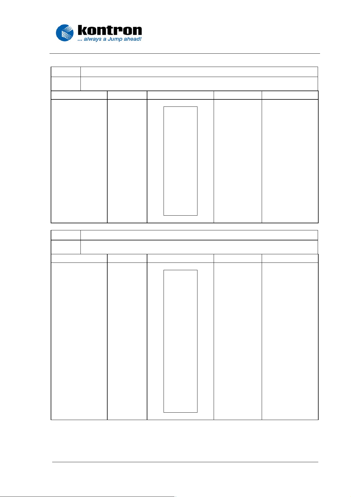
4.1
Description Name Pin
Power Ground GND
Latch pulse LP
Power Ground GND
Panel Data R1 R1
Panel Data R3 R3
Panel Data R5 R5
Panel Data G0 G0
Panel Data G2 G2
Panel Data G4 G4
Power Ground GND
Panel Data B1 B1
Panel Data B3 B3
Panel Data B5 B5
Data Enable DE
Panel Power PANEL_VCC
Up/Down rotate U/D
Caution! The supply voltage of the flat panel must be configured on the flat
panel controller. See the technical manual of the specific controller.
Input Flatfoil cable
Flatfoil connector X2
Panel connector X1
Input Flatfoil cable
Flatfoil cable 32 Contacts, ends opposite side, 0,5mm Pitch
1 O O 2
3 O O 4
5 O O 6
7 O O 8
9 O O 10
11 O O 12
13 O O 14
15 O O 16
17 O O 18
19 O O 20
21 O O 21
23 O O 24
25 O O 26
27 O O 28
29 O O 30
31 O O 32
Pin Name Description
SCLK Data clock
FLM First Line Marker
R0 Panel Data R0
R2 Panel Data R2
R4 Panel Data R4
GND Power Ground
G1 Panel Data G1
G3 Panel Data G3
G5 Panel Data G5
B0 Panel Data B0
B2 Panel Data B2
B4 Panel Data B4
GND Power Ground
PANEL_VCC Panel Power
R/L Right/Left rotate
PANEL_VCC Panel Power
KAB-FLEX32-TSDD08
04.02.2004 4
Page 6
Kontron Hamburg GmbH & Co.KG
22081 Hamburg / Germany
Fax: +49 (0)40 20 00 90-10
http:// www.kontron-hh.com
Marschnerstieg 7
Fon: +49 (0)40 20 00 90-0
4.2
Flatfoil connector X2
Flatfoil 32 Contacts, Right Angle, Bottom Contact
Case/Size: 0,5mm Pitch, Series: 6210 / ZIF
Description Name Pin
Pin Name Description
Power Ground GND
Latch pulse LP
Power Ground GND
Panel Data R1 R1
Panel Data R3 R3
Panel Data R5 R5
Panel Data G0 G0
Panel Data G2 G2
Panel Data G4 G4
Power Ground GND
Panel Data B1 B1
Panel Data B3 B3
Panel Data B5 B5
Data Enable DE
Panel Power PANEL_VCC
Up/Down rotate U/D
1 O O 2
3 O O 4
5 O O 6
7 O O 8
9 O O 10
11 O O 12
13 O O 14
15 O O 16
17 O O 18
19 O O 20
21 O O 21
23 O O 24
25 O O 26
27 O O 28
29 O O 30
31 O O 32
SCLK Data clock
FLM First Line Marker
R0 Panel Data R0
R2 Panel Data R2
R4 Panel Data R4
GND Power Ground
G1 Panel Data G1
G3 Panel Data G3
G5 Panel Data G5
B0 Panel Data B0
B2 Panel Data B2
B4 Panel Data B4
GND Power Ground
PANEL_VCC Panel Power
R/L Right/Left rotate
PANEL_VCC Panel Power
4.3
Panel connector X1
Board to Board Connector, Hirose DF9B-41S-1V
Case/Size: 1,0 mm Pitch
Description Name Pin
Pin Name Description
Power Ground GND
Power Ground GND
First Line Marker FLM
Power Ground GND
Panel Data R0 R0
Panel Data R2 R2
Panel Data R3 R3
Panel Data R5 R5
Power Ground GND
Panel Data G0 G0
Panel Data G2 G2
Panel Data G3 G3
Panel Data G5 G5
Power Ground GND
Panel Data B0 B0
Panel Data B2 B2
Panel Data B3 B3
Panel Data B5 B5
Data Enable DE
Panel Power PANEL_VCC
Up/Down rotate U/D
1 O O 2
3 O O 4
5 O O 6
7 O O 8
9 O O 10
11 O O 12
13 O O 14
15 O O 16
17 O O 18
19 O O 20
21 O O 21
23 O O 24
25 O O 26
27 O O 28
29 O O 30
31 O O 32
33 O O 34
35 O O 36
37 O O 38
39 O O 40
41 O
SCLK Data clock
LP Latch pulse
GND Power Ground
GND Power Ground
R1 Panel Data R1
GND Power Ground
R4 Panel Data R4
GND Power Ground
GND Power Ground
G1 Panel Data G1
GND Power Ground
G4 Panel Data G4
GND Power Ground
GND Power Ground
B1 Panel Data B1
GND Power Ground
B4 Panel Data B4
GND Power Ground
R/L Right/Left rotate
PANEL_VCC Panel Power
KAB-FLEX32-TSDD08
04.02.2004 5
Page 7
Kontron Hamburg GmbH & Co.KG
22081 Hamburg / Germany
Fax: +49 (0)40 20 00 90-10
http:// www.kontron-hh.com
Marschnerstieg 7
Fon: +49 (0)40 20 00 90-0
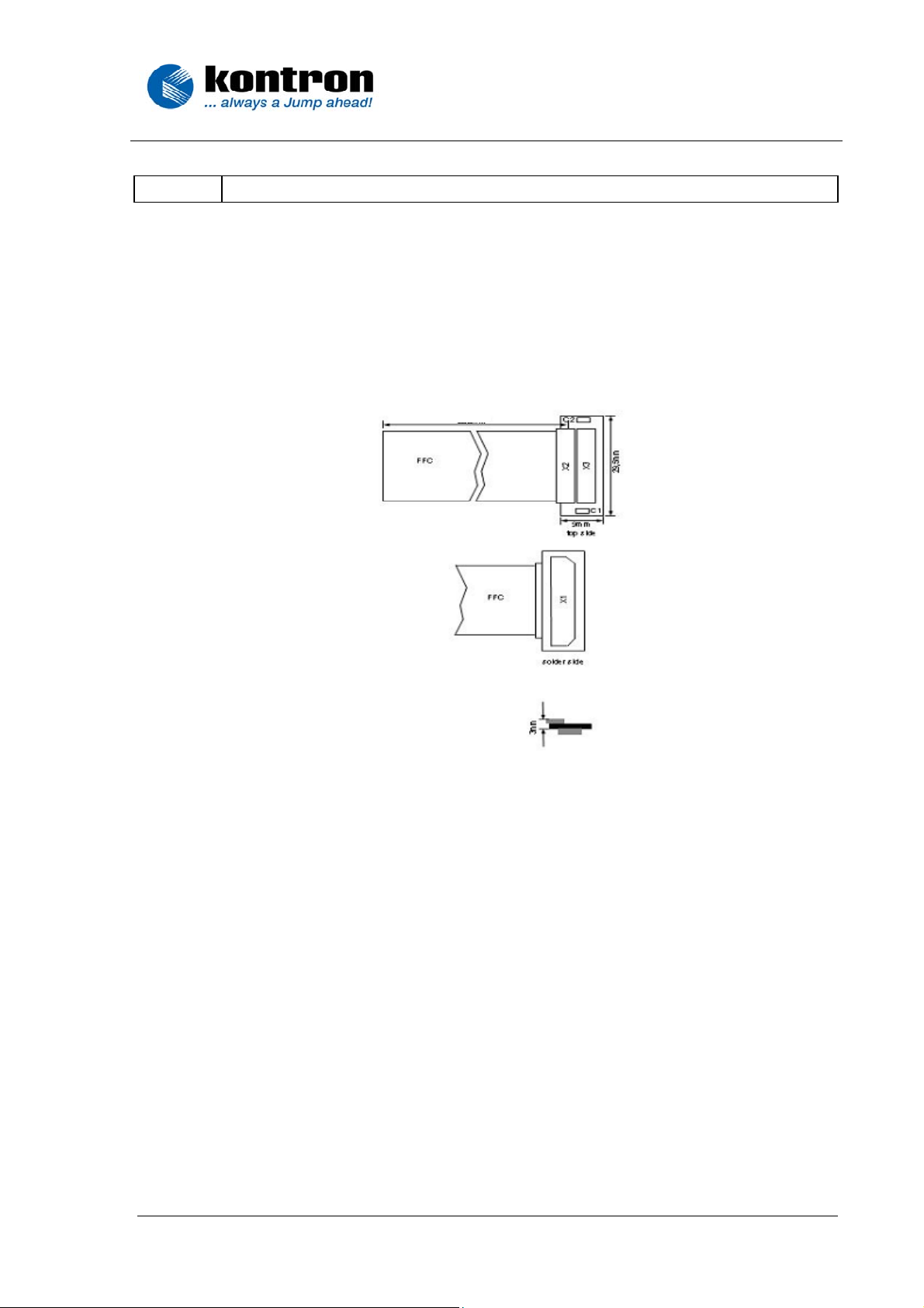
5.0 Layout / Dimensions
KAB-FLEX32-TSDD08
250mm
KAB-FLEX32-TSDD08
04.02.2004 6
Page 8
Kontron Hamburg GmbH & Co.KG
Marschnerstieg 7
22081 Hamburg / Germany
Fon: +49 (0)40 20 00 90-0
Fax: +49 (0)40 20 00 90-10
http:// www.kontron-hh.com
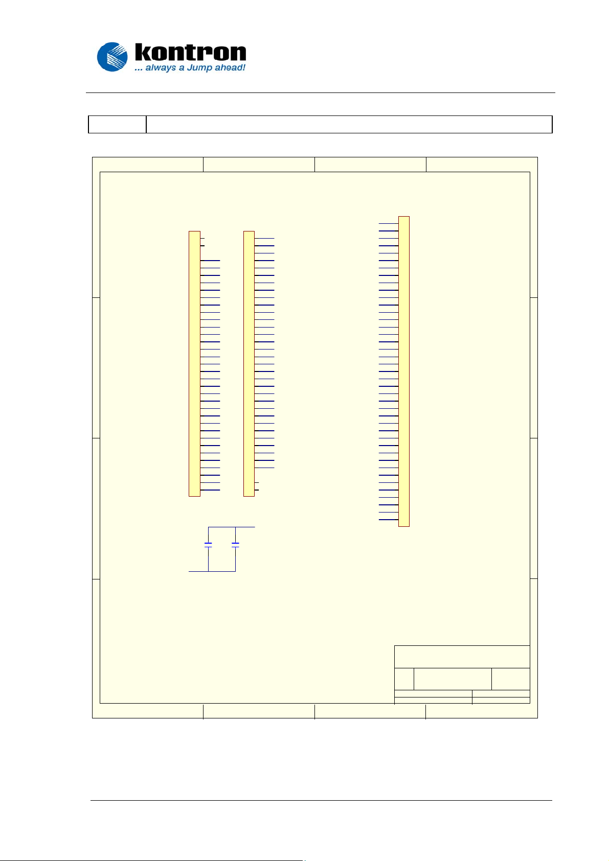
6.0 Schematics
321
X1
GND
D
C
B
X3
CON3 2
34
33
32
31
30
29
28
27
26
25
24
23
22
21
20
19
18
17
16
15
14
13
12
11
10
9
8
7
6
5
4
3
2
1
GND
GND
SCLK
LP
FLM
GND
R0
R1
R2
R3
R4
R5
GND
G0
G1
G2
G3
G4
G5
GND
B0
B1
B2
B3
B4
B5
GND
MOD
VCC
VCC
R/L
U/ D
VCC
C1
C3u3S05V6C2C3 u3S0 5V6
VCC
X2
GND
1
SCLK
2
LP
3
FLM
4
GND
5
R0
6
R1
7
R2
8
R3
9
R4
10
R5
11
GND
12
G0
13
G1
14
G2
15
G3
16
G4
17
G5
18
GND
19
B0
20
B1
21
B2
22
B3
23
B4
24
B5
25
GND
26
MOD
27
VCC
28
VCC
29
R/L
30
U/ D
31
VCC
32
33
34
CON3 2
1
SCLK
2
GND
3
LP
4
FLM
5
GND
6
GND
7
GND
8
R0
9
R1
10
R2
11
GND
12
R3
13
R4
14
R5
15
GND
16
GND
17
GND
18
G0
19
G1
20
G2
21
GND
22
G3
23
G4
24
G5
25
GND
26
GND
27
GND
28
B0
29
B1
30
B2
31
GND
32
B3
33
B4
34
B5
35
GND
36
MOD
37
R/L
38
VCC
39
VCC
40
U/ D
41
CON4 1
X1 pl a ce d o n BOT TOM L AYE R
4
D
C
B
X2, X3, C1 and C2 placed on TOP LAYER
shapes of X2 a nd X3 ca n be c ombine d
A
1 2 34
Title
LCD Ad ap ter FFC 32 t o HRS 41
Nu mbe r Re vi sio nSize
A4
Date: 22-Oct-2002 She et of
File: C:\proj\tsdd03\te st.DDB Drawn By:
LCAZS120 2.0
11
A. Ka ud e l , JUMPt e c AG
KAB-FLEX32-TSDD08
04.02.2004 7
A
Page 9
Kontron Hamburg GmbH & Co.KG
22081 Hamburg / Germany
Fax: +49 (0)40 20 00 90-10
http:// www.kontron-hh.com
Marschnerstieg 7
Fon: +49 (0)40 20 00 90-0
7.0 Technical Support
Please report any errors or problems to this email address:
sales-graphic@kontron.com
.
Normally, there is no telephone support. In your email message, please
include the following information :
Company Name
Your Name
Address
Email
Telephone/Fax
Exact description of the hardware, etc.
Exact description of the software in used (for example: Win 95 with
driver XYZ )
Exact description of the error.
8.0 Revision History
Date Author Version Description
04.02.2004 S. Leuchtenberger 1.0 Initial Release
KAB-FLEX32-TSDD08
04.02.2004 8
Page 10
Kontron Embedded Modules GmbH
22081 Hamburg / Germany
Fax: +49 (0)40 20 00 90-10
www.kontron-emea.com/flatpanel
Marschnerstieg 7
Fon: +49 (0)40 20 00 90-0
aFLAT-Series
CRTtoLCD-5
Technical Manual
Table of Contents
1.0 General Information and Important Notes
1.1 Introduction
1.2 Technical Information Summary
1.3 Connectors
1.4
1.5 Technical Specification
1.6 Supported Video Modes
1.7 Layout / Dimensions
1.8 Serial OSD
1.9 Technical Support
2.0 Revision History
On Screen Display
CRTtoLCD-5
04.10.2005 1
Page 11

Kontron Embedded Modules GmbH
22081 Hamburg / Germany
Fon: +49 (0)40 20 00 90-0
Fax: +49 (0)40 20 00 90-10
www.kontron-emea.com/flatpanel
1.0
Copyright 2005 by Kontron Embedded Modules GmbH.
User Information
In this document Kontron Embedded Modules GmbH will also be referred
to by the short form “Kontron Embedded Modules GmbH”.
The information in this document has been carefully checked and is
believed to be accurate and reliable. However, no responsibility is
assumed for inaccuracies. Furthermore, Kontron Embedded Modules
GmbH reserves the right to make changes to any portion of this manual to
improve reliability, function or design. Kontron Embedded Modules GmbH
does not assume any liability for any product or circuit described herein.
1.0
AT and IBM are trademarks of International Business Machines.
Trademarks
XT, AT, PS/2 and Personal System/2 are trademarks of International
Business Machines Corporation.
Microsoft is a registered trademark of Microsoft Corporation.
Intel is a registered trademark of Intel Corporation.
All other products and trademarks mentioned in this manual are
trademarks of their respective owners.
The reproduction, transmission or use of this document or its contents is
not permitted without expressed written authority.
Offenders will be liable for damages. All rights created by patent grant or
registration of a utility model or design, are reserved.
1.0
For the circuits, descriptions and tables indicated no responsibility is
General
assumed as far as patents or other rights of third parties are concerned.
The information in the Technical Descriptions describes the type of the
boards and shall not be considered as assured characteristics.
The reproduction, transmission or use of this document or its contents is
not permitted without express written authority. Offenders will be liable for
damages. All rights, including rights created by patent grant or registration
of a utility model or design, are reserved.
Marschnerstieg 7
CRTtoLCD-5
04.10.2005 2
Page 12

Kontron Embedded Modules GmbH
22081 Hamburg / Germany
Fax: +49 (0)40 20 00 90-10
www.kontron-emea.com/flatpanel
Marschnerstieg 7
Fon: +49 (0)40 20 00 90-0
1.0
Each board is carefully and thoroughly tested before being shipped. If,
Warranty
however, problems should occur during the operation, please check your
user specific settings of all boards included in your system. This is often
the source of the fault. If a board is defective, it can be sent to your supplier
for repair. Please take care of the following steps:
- The board returned should correspond to the factory default
settings since a test is only possible under these settings.
- In order to repair your board as fast as possible , we require some
additional information from you. Please fill out the attached Repair
Form and include it with the defective board.
- If possible, the board will be upgraded to the latest version without
additional cost.
- Upon receipt of the board, please be aware that your user specific
settings were changes during the test.
Within the guarantee, the repair is free as long as the guarantee conditions
were kept. If no fault has been found, you will be charged with the test cost
due to the high test expenditure. Repairs outside of the guarantee will be
charged.
This Kontron Embedded Modules GmbH product is warranted against
defects in material and workmanship for our guaranteed warranty period
from the date of shipment. During the warranty period, Kontron Embedded
Modules GmbH will, at its option, either repair or replace products which
prove to be defective.
For warranty service or repair, the product must be returned to a service
facility designated by Kontron Embedded Modules GmbH.
The foregoing warranty shall not apply to defects resulting from improper or
inadequate maintenance or handling by buyer, unauthorized modification
or misuse, operation outside of the environmental specifications for the
product, or improper installation or maintenance.
Kontron Embedded Modules GmbH will not be responsible for any defects
or damages due to a faulty Kontron Embedded Modules GmbH product
other than the products supplied by
Kontron Embedded Modules GmbH.
CRTtoLCD-5
04.10.2005 3
Page 13

Kontron Embedded Modules GmbH
22081 Hamburg / Germany
Fax: +49 (0)40 20 00 90-10
www.kontron-emea.com/flatpanel
Marschnerstieg 7
Fon: +49 (0)40 20 00 90-0
1.1 Introduction
The CRTtoLCD-5 is a highly integrated TFT panel interface controller,
which allows an easy adaptation of standard video input sources like
DVI or analog RGB to a digital TFT panel. The CRTtoLCD-5 need only one
single 12V DC power supply and incorporates all needed functionality to
build up a full featured TFT monitor. The card generates the necessary
power sequencing for the flat screen. The highly flexible architecture of the
CRTtoLCD-5 panel interface allows adapting nearly any available TFT
panel. Therefore a variety of panel adapters and programming are
available on request.
1.2 Technical Information Summary
Features
- Zoom ( from VGA ) and shrink ( from UXGA ) scaling
- Integrated 8-bit triple-channel ADC / PLL
- Integrated Ultra-Reliable DVI
- embedded Microcontroller with serial ROM Interface
- On-chip versatile OSD engine
- All system clocks synthesized from a single external crystal
- Programmable gamma correction (CLUT)
- RealColor control provide sRGB compliance
- Adjustable back light intensity control
- Light sensor input
- Independent Panel Power supply
- Low EMI and power saving features
High-Quality Advanced Scaling
- Fully programmable zoom ratios
- High quality shrink capability from UXGA resolution
- RealRecovery function provides full color recovery image for refresh rates
higher than those supported by the LCD panel
- Moiré cancellation
Analog RGB Input Port
− Supports up to SXGA at 75Hz / UXGA 60 Hz
Auto-Configuration / Auto-Detection
− Phase and image positioning
− Input format detection
− Compatibility with all graphic cards and standard VESA
modes
Ultra-Reliable DVI Compliant Input Port
− Operating up to 165 MHz (up to UXGA 60 Hz)
− Direct connect to all DVI compliant digital transmitters
TM
1.0 compliant receiver
CRTtoLCD-5
04.10.2005 4
Page 14

Kontron Embedded Modules GmbH
22081 Hamburg / Germany
Fax: +49 (0)40 20 00 90-10
www.kontron-emea.com/flatpanel
Marschnerstieg 7
Fon: +49 (0)40 20 00 90-0
1.2 Technical Information Summary
RealColor
− Digital brightness and contrast controls
- TV color controls including hue and saturation control
- Flesh tone adjustment
- Full color matrix allows end users to experience the same color as viewed
on CRTs and other displays ( e.g. sRGB compliance )
LVDS Output Format
- Single / double channel up to SXGA 75 Hz output
- Support for 8 or 6-bit panels (with high quality dithering)
- One or two pixel output format
TTL Output Format
- Digital RGB panel 18-Bit interface
On-chip OSD Controller
- On-chip RAM for downloadable menus
- 1,2 and 4-Bit per pixel character cells
- Horizontal and vertical stretch of OSD menus
- Blinking, transparency and blending
- Proportional fonts
Display Interface Features :
- Control signal generation for backlight inverter
- backlight dimming support
- voltage generation and power sequence control for panel
- Flat screens can be used with either 3.3V, 5V or 12V.
- Digital RGB panel 18-Bit interface (optional)
- LVDS panel interface ( one and double port up to 24 Bit )
Operating Features :
- 5 or 6 (optional) button user interface
- On Screen Display ( OSD ) control for full features
- Full multi sync capable
- VESA DPMS and DDC2B support
- Single voltage supply ( +12V DC )
- No software drivers needed!
Technology
CRTtoLCD-5
04.10.2005 5
Page 15

1.3 Connectors
1.3.1
1.3.2
1.3.3
1.3.4
1.3.5
1.3.6
1.3.7
1.3.8
1.3.9
1.3.10
1.3.11
*Note1 can vary. Depends on version of CRTtoLCD-5
RGB analog input CN2
OSD keypad connector CN500 or CN501 *Note1
Backlight connector CN101, CN102 *Note1
Serial Port connector CN200
KAB-FLEX32 Interface CN400 *Note1
KAB-JILI30-Interface CN100 *Note1
DC Power supply CN300, CN301
Flatpanel power supply configuration JP102
Backlight control configuration JP100, JP101
ADC Input connector CN201
DVI input connector CN1
Kontron Embedded Modules GmbH
22081 Hamburg / Germany
Fax: +49 (0)40 20 00 90-10
www.kontron-emea.com/flatpanel
Marschnerstieg 7
Fon: +49 (0)40 20 00 90-0
CRTtoLCD-5
04.10.2005 6
Page 16

Kontron Embedded Modules GmbH
22081 Hamburg / Germany
Fax: +49 (0)40 20 00 90-10
www.kontron-emea.com/flatpanel
Marschnerstieg 7
Fon: +49 (0)40 20 00 90-0
1.3.1 RGB Analog Input CN2
Name Pin Description
RED
GREEN
BLUE
NC
GND
GND
GND
GND
DDC+5V
GND
NC
DDC_SDA
HSYNC
VSYNC
DDC_SCL
High Density Sub-D-Connector 15 Contacts, Receptacle
Case/Size : Right Angle, Through Hole
1 O
2 O
3 O
4 O
5 O
6 O
7 O
8 O
9 O
10 O
11 O
12 O
13 O
14 O
15 O
analog input red
analog input green
analog input blue
Not connected
Analog Ground
Analog Ground red
Analog Ground green
Analog Ground blue
Supply Voltage for DDC
Analog Ground
Not connected
DDC serial data
Horizontal sync input
Vertical sync input
DDC serial clock
1.3.2 OSD Keypad Connector CN501
Description Name Pin
+5V Keypad Power out VCC
Keypad Button (Exit) KEY
Keypad Button (Right) KEY
Transmit Data (TTL) TXD
LED Green *Note1 LED 1
Not connected NC
Power Ground GND
*Note1 Max. 4,5 mA output current
04.10.2005 7
14 Contacts IDC Connector, Gold plated, double row,
vertical mount, through hole
1 O O 2
3 O O 4
5 O O 6
7 O O 8
9 O O 10
11 O O 12
13 O O 14
CRTtoLCD-5
Pin Name Description
LED 2 LED Red *Note1
KEY Keypad Button (Menu)
KEY Keypad Button (Left)
RXD Receive Data (TTL)
KEY Keypad Button (Power)
Vcc12 +12V Power Keypad out
GND Power Ground
Page 17

1.3.2 OSD keypad connector CN500
Connector: Molex 53261-1490
Kontron Embedded Modules GmbH
22081 Hamburg / Germany
Fax: +49 (0)40 20 00 90-10
www.kontron-emea.com/flatpanel
Marschnerstieg 7
Fon: +49 (0)40 20 00 90-0
Matching Connector: Molex 51021-1400
Connector Single Row, 14 contacts, Case/Size : Right Angle, 1,25mm Pitch
Name Pin Description
LED2
LED1
GND
KEY
GND
KEY
KEY
NC
NC
KEY
KEY
KEY
GND
VDD
1 O
2 O
3 O
4 O
5 O
6 O
7 O
8 O
9 O
10 O
11 O
12 O
13 O
14 O
LED Red *Note1
LED Green *Note1
Key Power Ground
Key Button( Power )
Key Power Ground
Key Button( Menu )
Key Button( Right )
Not Connected
Not Connected
Key Button( Left )
Key Button( Exit )
Key Button( Autoadjust )
Power Ground
+ 3.3 V Keypad Power out
Key Active = Button connected to Power Ground
*Note1 Max. 4,5 mA output current
1.3.3 Backlight Connector CN102
Connector: Molex 53261-0790
Matching Connector: Molex 51021-0700
Connector Single Row, 7 Contacts, Case/Size : Right Angle, 1,25mm Pitch
Pin
O
O
O
O
O
O
O
Name Description
NC
1
BKLTADJ
2
GND
3
Backlight power supply
4
Backlight power supply
5
GND
6
BLON
7
Not connected
analog 0V to +5V or 0V to +12V (refer JP101)
Power Ground
Typ. +12V (Note same as DC Input Voltage ,
1Amp. Per Contact allowed)
Power Ground
Backlight control signal (TTL, refer to JP100)
Polarity settings
CRTtoLCD-5
04.10.2005 8
Page 18

1.3.3 Backlight Connector CN101
Connector: Molex 53261-1090
Kontron Embedded Modules GmbH
22081 Hamburg / Germany
Fax: +49 (0)40 20 00 90-10
www.kontron-emea.com/flatpanel
Marschnerstieg 7
Fon: +49 (0)40 20 00 90-0
Matching Connector: Molex 51021-1000
Connector Single Row, 10 Contacts, Case/Size : Right Angle, 1,25mm Pitch
Pin Name Description
O
O
O
O
O
O
O
O 8
O 9
O 10
BLON
1
GND
2
GND
3
Backlight power supply
4
Backlight power supply
5
Backlight power supply
6
Backlight power supply
7
GND Power Ground
GND Power Ground
BKLTADJ analog 0V to +5V or 0V to +12V (refer to JP101)
Backlight control signal (TTL, refer to JP100)
Power Ground
Power Ground
Typical. +12V (Note same as DC Input Voltage ,
1 Ampere per contact allowed)
1.3.4 Serial Port connector CN200
The OSD ( On Screen Display ) can be controlled either trough
the keypad or the serial connector CN500/501 for configuration
purposes or mass production. See also chapter 1.8 for detailed
description.
Caution ! The transmit and receive signals have TTL level!
Connector: Molex 53261-0490
Matching Connector: Molex 52021-0400
Pin Name Description
O
O
O
O
1
2
3
4
VCC +5V DC Power (output)
RXD Receive Data Signal
TXD Transmit Data Signal
GND Power Ground
CRTtoLCD-5
04.10.2005 9
Page 19

1.3.5 KAB-FLEX32-Interface CN400
Kontron Embedded Modules GmbH
22081 Hamburg / Germany
Fax: +49 (0)40 20 00 90-10
www.kontron-emea.com/flatpanel
Marschnerstieg 7
Fon: +49 (0)40 20 00 90-0
This connector directly matches through an interface cable for
31/41 pin VGA/SVGA TFT interface. All flat screen signals are
LVTTL compatible (3.3V )
Description Name Pin Pin Name Description
Power Ground GND
Latch pulse LP
Power Ground GND
Panel Data RED1 P1
Panel Data RED3 P3
Panel Data RED5 P5
Panel Data GREEN0 P6
Panel Data GREEN2 P8
Panel Data GREEN4 P10
Power Ground GND
Panel Data BLUE1 P13
Panel Data BLUE3 P15
Panel Data BLUE5 P17
Data Enable MOD ( DE )
Panel Power *Note1 Panel_VCC
Up/Down rotate U/D
Flatfoil Connector 32 Contacts, Right Angle, Bottom Contact
Case/Size : 0,5mm Pitch, ZIF
1 O O 2
3 O O 4
5 O O 6
7 O O 8
9 O O 10
11 O O 12
13 O O 14
15 O O 16
17 O O 18
19 O O 20
21 O O 22
23 O O 24
25 O O 26
27 O O 28
29 O O 30
31 O O 32
SCLK Data clock
FLM First Line Marker
P0 Panel Data R0
P2 Panel Data RED2
P4 Panel Data RED4
GND Power Ground
P7 Panel Data GREEN1
P9 Panel Data GREEN3
P11 Panel Data GREEN5
P12 Panel Data BLUE0
P14 Panel Data BLUE2
P16 Panel Data BLUE4
GND Power Ground
Panel_VCC Panel Power *Note1
R/L Right/Left
NC Not connected
*Note1: Refer to JP102 how to configure the panel power
CRTtoLCD-5
04.10.2005 10
Page 20

1.3.6 KAB-JILI30-Interface CN100
Connector: JAE FI-X30S-HF
Kontron Embedded Modules GmbH
22081 Hamburg / Germany
Fax: +49 (0)40 20 00 90-10
www.kontron-emea.com/flatpanel
Marschnerstieg 7
Fon: +49 (0)40 20 00 90-0
Matching Connector: JAE FI-X30H
Name Pin Description
FTX0FTX0+
FTX1FTX1+
FTX2FTX2+
GND
FTXCFTXC+
FTX3FTX3+
STX0STX0+
GND
STX1STX1+
GND
STX2STX2+
STXCSTXC+
STX3STX3+
GND
NC
PPWR
NC
PANEL_VCC
PANEL_VCC
PANEL_VCC
1 O
2 O
3 O
4 O
5 O
6 O
7 O
8 O
9 O
10 O
11 O
12 O
13 O
14 O
15 O
16 O
17 O
18 O
19 O
20 O
21 O
22 O
23 O
24 O
25 O
26 O
27 O
28 O
29 O
30 O
Even Receiver Signal
Even Receiver Signal
Even Receiver Signal
Even Receiver Signal
Even Receiver Signal
Even Receiver Signal
Power Ground
Even Clock Signal
Even Clock Signal
Even Receiver Signal
Even Receiver Signal
Odd Receiver Signal
Odd Receiver Signal
Power Ground
Odd Receiver Signal
Odd Receiver Signal
Power Ground
Odd Receiver Signal
Odd Receiver Signal
Odd Clock Signal
Odd Clock Signal
Odd Receiver Signal
Odd Receiver Signal
Power Ground
Not Connected
Controls Panel Digital Power
Not Connected
Panel Power (refer to JP102)
Panel Power (refer to JP102)
Panel Power (refer to JP102)
1.3.7 DC Power Supply CN300
Apply operating voltage using connector CN300 or CN301.
4 Contact Connector, Single Row, Right Angle, Polarization, through hole
Pin Name Description
O
O
O
O
NC Not connected
1
GND Power Ground
2
GND Power Ground
3
+12V +12 V DC Power Input
4
CRTtoLCD-5
04.10.2005 11
Page 21

Kontron Embedded Modules GmbH
22081 Hamburg / Germany
Fax: +49 (0)40 20 00 90-10
www.kontron-emea.com/flatpanel
1.3.7 DC Power Supply CN301
Marschnerstieg 7
Fon: +49 (0)40 20 00 90-0
Apply operating voltage using connector CN300 or CN301.
DC POWER JACK, Case/Size : PCB-Mount 2mm Pin Diameter
Pin Name Description
O
O
+12V +12 V DC Power Input
1
GND Power Ground
2
1.3.8 Flatpanel Power Configuration JP102
Short pins 1-2 or 2-3 or leave open to choose required voltage
supply.
Caution ! Only one configuration for flatpanel is allowed,
otherwise the board is permanently damaged.
Connector Single Row 2,54 mm, 3 Contacts, Gold plated
Case/Size : Vertical, Through Hole
1 2 3 Pin 2-3 1-2 open Delivery Default
O O O
+12V +5V +3.3V
Never unplug/replug while in use!
1-2 closed
1.3.9 Backlight Control Configuration JP100
1 2 3 Pin 2-3 1-2 Delivery Default
Use JP100 to control polarity of backlight control signal.
Connector Single Row 2,54 mm, 3 Contacts, Gold plated
Case/Size : Vertical, Through Hole
O O O
/BLON BLON
Never unplug/replug while in use!
1-2 closed
1.3.9 Backlight Output Adjust Configuration JP101
1 2 3 Pin 2-3 1-2 Delivery Default
04.10.2005 12
Use JP101 to set correct backlight adjust range I-out 20mA max.
Connector Single Row 2,54 mm, 3 Contacts, Gold plated
Case/Size : Vertical, Through Hole
O O O
1-2 closed
Typ. 0-12V Typ. 0-5V
Never unplug/replug while in use!
CRTtoLCD-5
Page 22

Kontron Embedded Modules GmbH
22081 Hamburg / Germany
Fon: +49 (0)40 20 00 90-0
Fax: +49 (0)40 20 00 90-10
www.kontron-emea.com/flatpanel
1.3.10 ADC Input Connector CN201
(Light Sensor Input)
*Note1 Input range is 0 - 3V. Onboard pulled up to DVDD3.3 through 4, 7 KΩ resistor.
Pin Name Description
O
O
O
O
O
4
5
Connector: Molex 53261-0590
Matching Connector: Molex 52021-0500
GND Power Ground
1
ADC1 ADC1 Input *Note1
2
DVDD3.3 3.3V output source (max.50mA)
3
ADC2 ADC2 Input *Note1
GND Power Ground
1.3.11 DVI-D Input Connector CN1
This input supports the connection of DVI capable video cards
and supports resolutions from 640x480 up to 1600x1200.
Description Name Pin Pin Name Description
Receiver Signal(-) ( RX2- ) RX2Power Ground GND
Not connected NC
I2C Data SDA
Receiver Signal(-) ( RX1- ) RX1Power Ground GND
Not connected NC
Power Ground GND
Receiver Signal(-) ( RX0- ) RX0Power Ground GND
Not connected NC
Clock Signal(+) (RXC+) RXC+
Not connected NC
Not connected NC
Not connected NC
Connector 24 Contacts, Gold plated
Case/Size : Vertical, Through Hole
1 O O 2
3 O O 4
5 O O 6
7 O O 8
9 O O 10
11 O O 12
13 O O 14
15 O O 16
17 O O 18
19 O O 20
21 O O 22
23 O O 24
C1 O O C2
C3 O O C4
C5 O O C5-1
RX2+ Receiver Signal(+) ( RX2+ )
NC Not connected
SCL I2C clock
NC Not connected
RX1+ Receiver Signal(+) ( RX1+ )
NC Not connected
+5V +5V from DVI video card
HP Hot Plug
RX0+ Receiver Signal(+) ( RX0+ )
NC Not connected
GND Power Ground
RXC- Clock Signal(-) (RXC-)
NC
NC
NC
Not connected
Not connected
Not connected
Marschnerstieg 7
CRTtoLCD-5
04.10.2005 13
Page 23

Kontron Embedded Modules GmbH
22081 Hamburg / Germany
Fax: +49 (0)40 20 00 90-10
www.kontron-emea.com/flatpanel
Marschnerstieg 7
Fon: +49 (0)40 20 00 90-0
1.4 On Screen Display
Note: All changed values will only be saved by selecting “Exit” from the OSD.
Input Select
Select VGA Press “Osd” Select VGA input
Select DVI Press “Osd” Select DVI input
Exit Press “Osd” Exit menu
Brightness
Brightness Press “Osd” to enter
Contrast Press “Osd” to enter
Backlight Brightness Press “Osd” to enter
Backlight Mode Use “Up” and “Down” Enter Backlight Mode submenu
- Manual Backlight Use “Up” and “Down” Control backlight over the OSD
- External Backlight Control Use “Up” and “Down” Enable external control of backlight
- Exit Exit submenu
Exit Press “Osd” Exit menu
With the OSD ( On Screen Display ) you can modify the settings and
control the special features of the CRTtoLCD-5. The OSD uses a number
of menus for making changes and turning the special features on or off.
The configuration can be done via the OSD-keypad (OSD-Panel-Kit).
To start the OSD press the “OSD” button on the keypad, after switching the
power supply on. If a valid flat panel configuration is installed, the OSD
Main Menu will be displayed.
To select an tab, simply use the button “UP” or ”DOWN” to move the
cursor to the tab you want and press button “OSD”. When you use the tab
“Exit” and press the “CONFIRM”-button, the OSD will be closed.
To use a tab menu, simply use “OSD”-button to select the field.
Use “UP” or “DOWN” to select a value for that field. The “Exit”-field on the
bottom-side on the tab will go up to the tab-selection. Simply press the
“OSD”-button.
If not, the adjusted values will be lost after loss of power.
Feature Button Description
Feature Button Description
Adjust brightness
Adjust with
“Up” and “Down”
Adjust contrast
Adjust with
“Up” and “Down”
Adjust backlight brightness
Adjust with
“Up” and “Down”
CRTtoLCD-5
04.10.2005 14
Page 24

Kontron Embedded Modules GmbH
22081 Hamburg / Germany
Fax: +49 (0)40 20 00 90-10
www.kontron-emea.com/flatpanel
Marschnerstieg 7
Fon: +49 (0)40 20 00 90-0
Color Settings
Feature Button Description
Auto Color Adjust Press “Osd” Adjust colors automatically
Switch sRGB Mode Press “Osd” Switch to sRGB mode
Color Temperature Press “Osd” Enter Color Temperature submenu
- Select Color Temperature Press “Osd” Select predefined color temperatures
- Adjust RGB Values Press “Osd” Enter Adjust RGB Values submenu
- Red Color Value Use “Up” and “Down” User defined value of color temperature
- Green Color Value Use “Up” and “Down” User defined value of color temperature
- Blue Color Value Use “Up” and “Down” User defined value of color temperature
- 4200K Press “Osd” Set predefined color temperature of 4200K
- 5000K Press “Osd” Set predefined color temperature of 5000K
- 6500K Press “Osd” Set predefined color temperature of 6500K
- 7500K Press “Osd” Set predefined color temperature of 7500K
- 9300K Press “Osd” Set predefined color temperature of 9300K
- Exit Press “Osd” Exit submenu
Exit Press “Osd” Exit menu
Image Settings
Feature Button Description
Auto Adjust Press “Osd” Adjust image automatically
Adjust Width Press “Osd” to enter
Adjust image width
Adjust with
“Up” and “Down”
Adjust Phase Press “Osd” to enter
Adjust image phase
Adjust with
“Up” and “Down”
Horizontal Pos Press “Osd” to enter
Adjust image horizontal position
Adjust with
“Up” and “Down”
Vertical Pos Press “Osd” to enter
Adjust image vertical position
Adjust with
“Up” and “Down”
Exit Press “Osd” Exit menu
CRTtoLCD-5
04.10.2005 15
Page 25

Kontron Embedded Modules GmbH
22081 Hamburg / Germany
Fax: +49 (0)40 20 00 90-10
www.kontron-emea.com/flatpanel
Marschnerstieg 7
Fon: +49 (0)40 20 00 90-0
Tools
Feature Button Description
OSD Settings Press “Osd” Enter OSD Settings submenu
- OSD Timeout Use “Up” and “Down” Set the OSD time to close automatically
- OSD Hor. Position Use “Up” and “Down” Set OSD horizontal position
- OSD Ver. Position Use “Up” and “Down” Set OSD vertical position
- OSD Orientation Press “Osd” Enter OSD Orientation submenu
- Standard Press “Osd” OSD standard orientation
- Rotate 90 Press “Osd” Set OSD orientation at 90 degrees
- Rotate 180 Press “Osd” Set OSD orientation at 180 degrees
- Rotate 270 Press “Osd” Set OSD orientation at 270 degrees
- Horizontal Mirror Press “Osd” View the OSD horizontally mirrored
- Exit Exit submenu
Factory Reset Press “Osd” Recall all default factory settings
Factory Color Reset Press “Osd” Recall the factory default color settings
Factory Position Reset Press “Osd” Recall the factory default position of screen
Sharpness Use “Up” and “Down” Adjust level of sharpness
Overlapped Mode Select Press “Osd” Select overlapped mode
Exit Press “Osd” Exit menu
Exit OSD Menu
Feature Button Description
Exit Press “Osd” Exit the OSD and save changes
CRTtoLCD-5
04.10.2005 16
Page 26

Kontron Embedded Modules GmbH
22081 Hamburg / Germany
1.5 Technical Specification
These values were measured with OSD-Panel attached and without
Fax: +49 (0)40 20 00 90-10
www.kontron-emea.com/flatpanel
Marschnerstieg 7
Fon: +49 (0)40 20 00 90-0
flatpanel and backlight inverter.
- Supply voltage at 25˚C without load:
Minimum supply voltage : + 11,4 V DC
Typical supply voltage : + 12,0 V DC
Absolute Maximum supply voltage : + 12.6 V DC
- Typical Input current at 25˚C without load:
CRTtoLCD-5 with input signal (XGA) : 250 mA
CRTtoLCD-5 with power down typical : 60 mA
- Input Supply voltage ripple : typical 100 mV peak to peak 0 – 20 MHz
- Current Rating of Flatpanel Power supply:
PANEL VCC Steady State 3V / 5V and 12V @ +-5% : 3A
PANEL VCC 5sec. -5% 3V3 @4,33A
PANEL VCC 5sec. -5% 5V @ 4,15A
PANEL VCC 5sec. -2% 12V @ 4A
Note: Output power without any switch or short circuit breaker
- Slewrate of Flatpanel Power supply with 3A load
PANEL VCC 3V3 302us
PANEL VCC 5V 408us
PANEL VCC 12V 1.7ms
- Voltage and Current Rating of Backlight Power supply:
Direct +12V Output voltage without any switch or short circuit breaker
CN400: Maximum output current 4A
CN401: Maximum output current 2A
There are no limitations between Backlight Power and Flatpanel Power
The only limitation is the capability of the DC Input Power supply
VGA connector signals :
Sync input voltage low : 0.8 V
Sync input voltage high : 2.4 V
RGB input voltage : 0 – 0.7 V with 75 Ohm external termination
RGB input current : 0 – 5 mA
- Temperature : ambient : 0˚ C – 60˚ C (*1)
Non operating : - 10˚ C – 85˚ C
(*1) The maximum temperature on the module surface can exceed above
mentioned ambient temperature. It is the user responsibility to keep this
temperature within the above specification.
- Thermal gradient : operating : 25˚ C per hour
non-operating : 40˚ C per hour
- Relative Humidity : operating : 10% - 90 % RH non-condensing
non operating : 5% - 95% RH non-condensing
CRTtoLCD-5
04.10.2005 17
Page 27

Kontron Embedded Modules GmbH
22081 Hamburg / Germany
Fax: +49 (0)40 20 00 90-10
www.kontron-emea.com/flatpanel
Marschnerstieg 7
Fon: +49 (0)40 20 00 90-0
1.5 Technical Specification
- Mechanical : Shock : 50G/20ms square wave maximum
Vibration : 1G/0-600Hz, dwell not to exceed
- Altitude : operating : 0 – 3000 m
non-operating : 0 – 5000 m
- Dimensions of the printed circuit board :
Width : 114.28 mm
Length : 179.07 mm
Thickness : 1.50 mm
- Dimensions of the module :
Width : 119.50 mm
Length : 179.07 mm
Height : 16.50 mm +2mm (*)
Note : The dimension of the module can change if cable, Adapter or
Keypad plugged in!
CRTtoLCD-5
04.10.2005 18
Page 28

Kontron Embedded Modules GmbH
22081 Hamburg / Germany
Fax: +49 (0)40 20 00 90-10
www.kontron-emea.com/flatpanel
Marschnerstieg 7
Fon: +49 (0)40 20 00 90-0
1.6 Supported Video Modes (Analog Input)
Video Mode Input Vertical refresh rate Mode standard
720 x 400 70 Hz DOS
640 x 350 70 Hz DOS
640 x 400 70 Hz DOS
640 x 480 59,9 Hz VGA
640 x 480 60 Hz VGA
640 x 480 72 Hz VGA
640 x 480 72,8 Hz VGA
640 x 480 75 Hz VGA
800 x 600 56,25 Hz SVGA
800 x 600 60 Hz SVGA
800 x 600 70 Hz SVGA
800 x 600 72 Hz SVGA
800 x 600 75 Hz SVGA
1024 x 768 60 Hz XGA
1024 x 768 70 Hz XGA
1024 x 768 72 Hz XGA
1024 x 768 75 Hz XGA
1152 x 864 60 Hz
1152 x 864 70 Hz
1152 x 864 75 Hz
1280 x 1024 60 Hz SXGA
1280 x 1024 70 Hz SXGA
1280 x 1024 75 Hz SXGA
1600 x 1200 60 Hz UXGA
Generally all VESA compatible video modes are supported. If modes are
not supported the controller displays “Invalid Mode” on the flat panel. In this
case use the Flat Panel Editor, available on request, to add this special
mode to the supported mode table.
Following modes are tested
1.6 Supported Video Modes (DVI Input)
Video Mode Input Vertical refresh rate Mode standard
640 x 480 60 Hz VGA
800 x 600 60 Hz SVGA
1024 x 768 60 Hz XGA
1280 x 1024 60 Hz SXGA
Generally all VESA compatible video modes are supported. If modes are
not supported the controller displays “Invalid Mode” on the flat panel. In this
case use the Flat Panel Editor, available on request, to add this special
mode to the supported mode table.
Following modes are tested
CRTtoLCD-5
04.10.2005 19
Page 29

Kontron Embedded Modules GmbH
22081 Hamburg / Germany
Fax: +49 (0)40 20 00 90-10
www.kontron-emea.com/flatpanel
Marschnerstieg 7
Fon: +49 (0)40 20 00 90-0
1.7 Layout/Schematics
CRTtoLCD-5
CRTtoLCD-5
04.10.2005 20
Page 30

Kontron Embedded Modules GmbH
22081 Hamburg / Germany
Fax: +49 (0)40 20 00 90-10
www.kontron-emea.com/flatpanel
Marschnerstieg 7
Fon: +49 (0)40 20 00 90-0
1.7 Layout/Schematics
OSD-Keypad “OSD-Panel“
Infrared receiver diode
(only on request)
Keypad JP1 connected to CN501 of CRTtoLCD-5!
CRTtoLCD-5
04.10.2005 21
Page 31

Kontron Embedded Modules GmbH
22081 Hamburg / Germany
Fax: +49 (0)40 20 00 90-10
www.kontron-emea.com/flatpanel
Marschnerstieg 7
Fon: +49 (0)40 20 00 90-0
1.8 Serial OSD
coming soon ...
CRTtoLCD-5
04.10.2005 22
Page 32

Kontron Embedded Modules GmbH
22081 Hamburg / Germany
Fax: +49 (0)40 20 00 90-10
www.kontron-emea.com/flatpanel
Marschnerstieg 7
Fon: +49 (0)40 20 00 90-0
1.9 Technical Support
Please report any errors or problems to this email address:
sales_graphic@kontron.com.
Normally, there is no telephone support. In your email message, please
include the following information :
Company Name
Your Name
Address
Email
Telephone/Fax
Exact description of the hardware, etc.
Exact description of the software used (for example: Win XP with
driver XYZ )
Exact description of the error.
CRTtoLCD-5
04.10.2005 23
Page 33

Kontron Embedded Modules GmbH
22081 Hamburg / Germany
Fax: +49 (0)40 20 00 90-10
www.kontron-emea.com/flatpanel
Marschnerstieg 7
Fon: +49 (0)40 20 00 90-0
2.0 Revision History
Date Author Version Description
26.06.2003 D.Finstel 1.0 Initial release
11.06.2004 M. Schulze 1.1 Updated specs
01.06.2005 L.Trotter 1.2 Change specs for new release
07.06.2005 V. Irion 1.3 Added supported video modes and OSD description
04.10.2005 V. Irion 1.4
Updated supported video modes
Updated connector CN201 and layout to version 1.02
CRTtoLCD-5
04.10.2005 24
 Loading...