

Page 1
JILI30 Development
KTD-S0018-0
Page 2

User Information
Table of Contents
» Table of Contents «
1 User Information .....................................................................................1
1.1 About This Document ................................................................................................................. 1
1.2 Copyright Notice ....................................................................................................................... 1
1.3 Trademarks .............................................................................................................................. 1
1.4 Standards ................................................................................................................................ 1
1.5 Warranty.................................................................................................................................. 1
1.6 Life Support Policy.....................................................................................................................2
1.7 Technical Support......................................................................................................................2
2 Introduction ...........................................................................................3
2.1 JILI30 Specification ................................................................................................................... 3
2.2 JILI30 Cable Overview ................................................................................................................ 3
2.3 KAB-ADAPT-LVDStoTTL Accessories ............................................................................................... 3
3 JILI30 Connector (SBC Side) ......................................................................4
4 JILI30 Cable (Examples)............................................................................5
4.1 KAB-JILI30-TXLD03 ................................................................................................................... 5
4.1.1 Display Connector Pinout ............................................................................................................................ 6
4.1.2 Display Connector...................................................................................................................................... 6
4.1.3 Cable Wiring ............................................................................................................................................. 7
4.2 KAB-JILI30-TELD02 ................................................................................................................... 7
4.2.1 Display Connector Pinout ............................................................................................................................ 8
4.2.2 Display Connector...................................................................................................................................... 8
4.2.3 Cable Wiring ............................................................................................................................................. 9
5 KAB-ADAPT-LVDStoTTL ............................................................................ 10
5.1 JILI30 Connector..................................................................................................................... 10
5.2 FLEX32 Connector.................................................................................................................... 11
5.3 Power Supply .......................................................................................................................... 12
5.3.1 Panel Power +3.3V ....................................................................................................................................12
5.3.2 Panel Power +5.0V ....................................................................................................................................12
5.4 FLEX32 Configurable Pins .......................................................................................................... 13
5.5 Electrical Specifications............................................................................................................ 13
6 FLEX32 Cable (Example) .......................................................................... 14
6.1 KAB-FLEX32-TVDD04 ................................................................................................................ 14
6.1.1 Display Connector Pinout ...........................................................................................................................14
6.1.2 Display Connector.....................................................................................................................................15
6.1.3 Cable Wiring ............................................................................................................................................15
Appendix A: Schematic KAB-ADAPT-LVDStoTLL ....................................................... 16
Appendix B: Document Revision History................................................................ 17
Display Cable Guide
Page 3

KTD-S0018-0 Page 1 User Information
1 User Information
1.1 About This Document
This document provides information about products from KONTRON Technology A/S and/or its subsidiaries.
No warranty of suitability, purpose or fitness is implied. While every attempt has been made to ensure that
the information in this document is accurate the information contained within is supplied “as-is” - no
liability is taken for any inaccuracies. Manual is subject to change without prior notice.
KONTRON assumes no responsibility for the circuits, descriptions and tables indicated as far as patents or
other rights of third parties are concerned.
1.2 Copyright Notice
Copyright © 2005 - 2010, KONTRON Technology A/S, ALL RIGHTS RESERVED.
No part of this document may be reproduced or transmitted in any form or by any means, electronically or
mechanically, for any purpose without the express written permission of KONTRON Technology A/S.
1.3 Trademarks
Brand and product names are trademarks or registered trademarks of their respective owners.
1.4 Standards
KONTRON Technology A/S is certified to ISO 9000 standards.
1.5 Warranty
This product is warranted against defects in material and workmanship for the warranty period from the
date of shipment. During the warranty period KONTRON Technology A/S will at its discretion decide to
repair or replace defective products.
Within the warranty period the repair of products is free of charge as long as warranty conditions are
observed.
The warranty does not apply to defects resulting from improper or inadequate maintenance or handling by
the buyer, unauthorized modification or misuse, operation outside of the product’s environmental specifications or improper installation or maintenance.
KONTRON Technology A/S will not be responsible for any defects or damages to third party products that
are caused by a faulty KONTRON Technology A/S product.
Display Cable Guide
Page 4

KTD-S0018-0 Page 2 User Information
1.6 Life Support Policy
KONTRON Technology's products are not for use as critical components in life support devices or systems
without express written approval of the general manager of KONTRON Technology A/S.
As used herein:
Life support devices or systems are devices or systems which
a) are intended for surgical implant into body or
b) support or sustain life and whose failure to perform, when properly used in accordance with instructions
for use provided in the labelling, can be reasonably expected to result in significant injury to the user.
A critical component is any component of a life support device or system whose failure to perform can be
reasonably expected to cause the failure of the life support device or system or to affect its safety or
effectiveness.
1.7 Technical Support
Please consult our web site at http://www.kontron.com/support for the latest product documentation,
utilities, drivers and support contacts
. In any case you can always contact your board supplier for technical
support.
Before contacting support please be prepared to provide as much information as possible:
Cable/Adapter identification:
Ë
Type
Ë
Part number (find PN on label)
Ë
Attached hardware (LCD panels ...)
Display Cable Guide
Page 5
KTD-S0018-0 Page 3 Introduction
2 Introduction
2.1 JILI30 Specification
The SBCs (Single Board Computer) from KONTRON Technology A/S only support the JILI30 LVDS interface.
JILI30 is a KONTRON hardware standard that interfaces a SBC via a LVDS connection to flatpanel displays.
The number 30 is choosen because of the used 30 pin cables. In general a simple inexpensive cable with
twisted lines is sufficient to establish the connection. For displays with a digital 18 bit interface and low
resolutions (VGA to SVGA) KONTRON offers a special adapter board (KAB-ADAPT-LVDStoTTL). This adapter
needs an additional FLEX32 cable for the connection to the display (the order implies 2 article numbers).
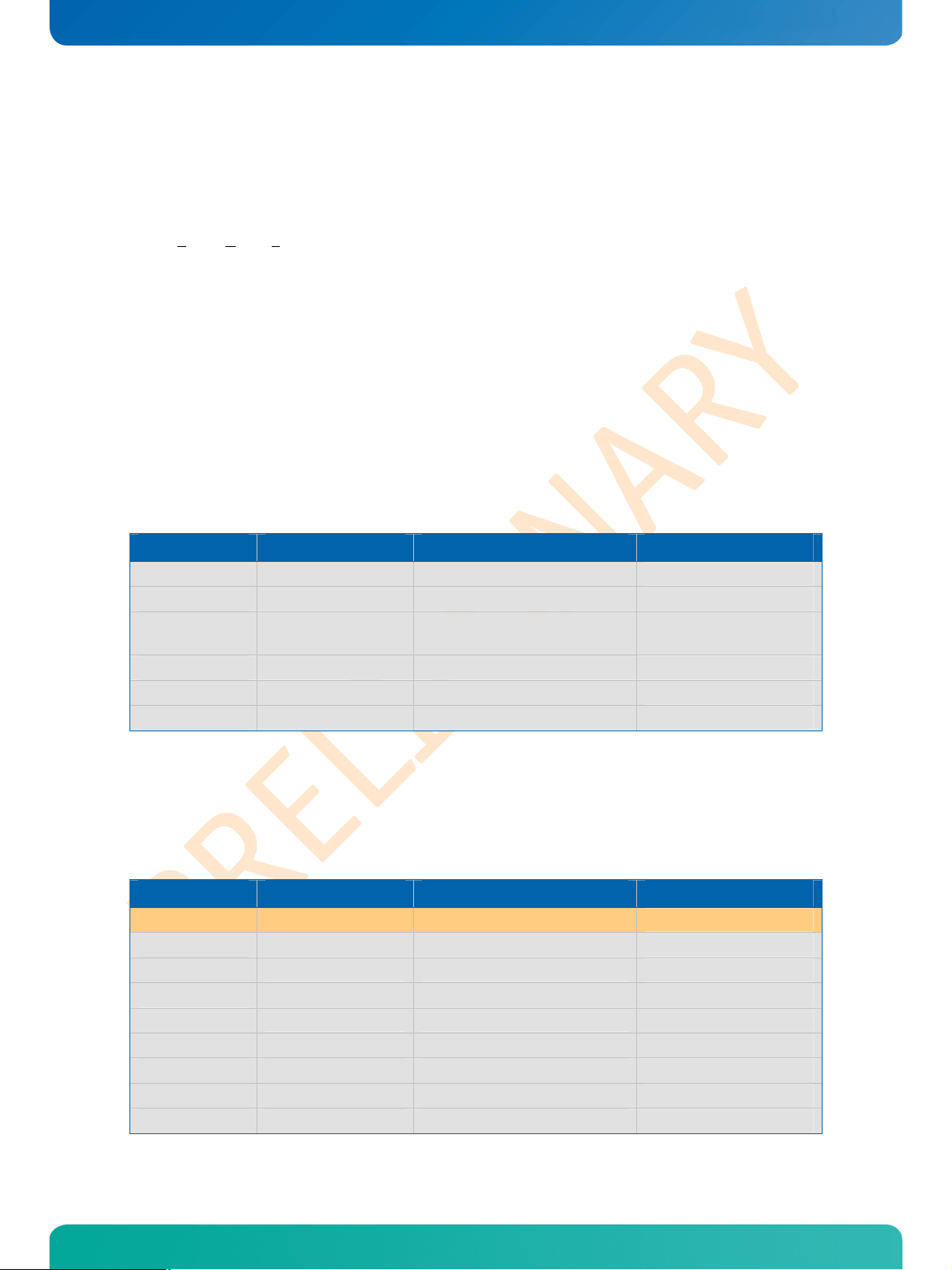
2.2 JILI30 Cable Overview
Please refer to the following matrix to choose the product that suits your needs best. The mentioned
resolution is not binding as the cable could also be used for other resolutions – the panel connector is the
most important part.
Article Number Designation Resolution Display (Example)
62514
62517
62518 KAB-JILI30-TSLD01
62520
62524
62526
KAB-JILI30-TXLD03 XGA (1024x768), 24 Bit
KAB-JILI30-TELD02 SXGA (1280x1024), 24 Bit
SVGA (800x600), 18 Bit
WVGA (800x480), 18 Bit
KAB-JILI30-TXLD06 XGA (1024x768), 18 Bit
KAB-JILI30-TXLD07 XGA (1024x768), 24 Bit
KAB-JILI30-TSLD02 SVGA (800x600), 18 Bit
SHARP LQ150X1LW71N
AUO M170EN07
AUO G104SN03 V2
PRIME VIEW PM070WL4
OPTREX T51756D121J-FW
NEC NL10276BC12-02
SANYO TM121SV-02L07
2.3 KAB-ADAPT-LVDStoTTL Accessories
Please refer to the following matrix to choose the product that suits your needs best. All displays that can
be connected using a KAB-FLEX32 cable have a 18 bit digital interface (18 signal lines).
Article Number Designation Resolution Display (Example)
61029 KAB-ADAPT-LVDStoTTL
64003
64006
64007
64008
64018
64019
64022
64026
KAB-FLEX32-TSDD01 SVGA (800x600), left hand, 50 cm
KAB-FLEX32-TVDD03 VGA (640x480), left hand, 20 cm
KAB-FLEX32-TVDD04 VGA (640x480), right hand, 20 cm
KAB-FLEX32-TSDD03 SVGA (800x600), left hand, 20 cm
KAB-FLEX32-TVDD08 VGA (640x480), 20 cm
KAB-FLEX32-TQDD01 QVGA (320x240), 20 cm
KAB-FLEX32-TVDD09 VGA (640x480), 20 cm
KAB-FLEX32-TSDD10 SVGA (800x600), 30 cm
Display Cable Guide
----
----
SHARP & NEC Panels
SHARP & NEC Panels
SHARP & NEC Panels
SHARP & NEC Panels
LG PHILIPS LB064V02
NEC NL3224BC35-20
LG PHILIPS LB104V03
AUO A201SN02
Page 6
KTD-S0018-0 Page 4 JILI30 Connector (SBC Side)
1
0
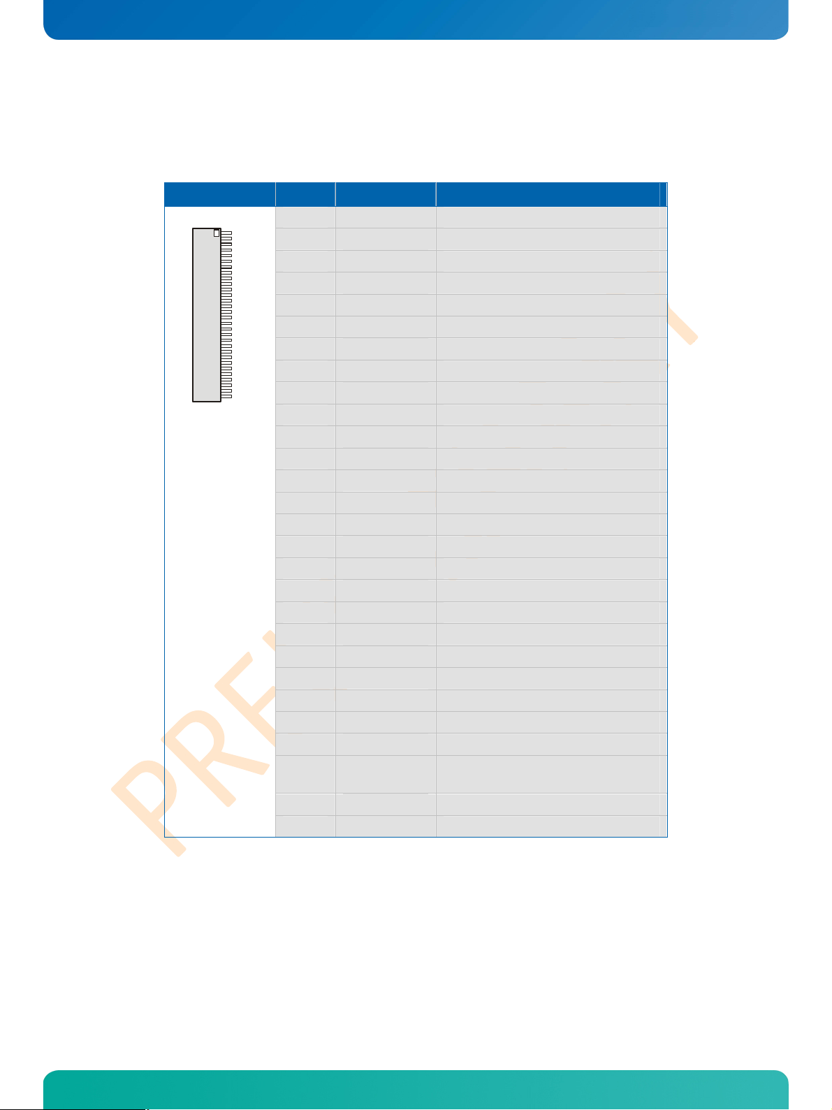
3 JILI30 Connector (SBC Side)
It's a single row connector with 30 contacts and 1.0 mm pitch (JAE, FI-X30S-HF or equivalent).
Header Pin Signal Name Function
3
1 FTX0- First channel data 0 output (negative)
2 FTX0+ First channel data 0 output (positive)
3 FTX1- First channel data 1 output (negative)
4 FTX1+ First channel data 1 output (positive)
5 FTX2- First channel data 2 output (negative)
6 FTX2+ First channel data 2 output (positive)
7 GND Ground
8 FTXC- First channel clock output (negative)
9 FTXC+ First channel clock output (positive)
10 FTX3- First channel data 3 output (negative)
11 FTX3+ First channel data 3 output (positive)
12 STX0- Second channel data 0 output (negative)
13 STX0+ Second channel data 0 output (positive)
14 GND Ground
15 STX1- Second channel data 1 output (negative)
16 STX1+ Second channel data 1 output (positive)
17 GND Ground
18 STX2- Second channel data 2 output (negative)
19 STX2+ Second channel data 2 output (positive)
20 STXC- Second channel clock output (negative)
21 STXC+ Second channel clock output (positive)
22 STX3- Second channel data 3 output (negative)
23 STX3+ Second channel data 3 output (positive)
24 GND Ground
25 SDA I2C data line
26 DATAENA
27 SCL I2C clock line
28 - 30 VCC Power +3.3V or +5.0V
Designator badly chosen - means:
Panel power enable (power sequencing)
Display Cable Guide
Page 7

KTD-S0018-0 Page 5 JILI30 Cable (Examples)
4 JILI30 Cable (Examples)
The following chapter describes the wiring of a JILI30 cable on two examples. KONTRON recommends that
the differential pairs should be twisted together to minimize crosstalk on the signal lines. It may seems as
if JILI30 cables are made for a specific display resolution. This is only particularly true.
The decision which cable can be used depends on the following criterias:
® Display connector type
® Pinout of display connector
® Number of channels/clocks (single or dual channel LVDS)
® Color depth (18 or 24 bit) respectively number of LVDS data pairs
4.1 KAB-JILI30-TXLD03
This cable can be used for single channel displays with 24 bit color depth (example SHARP LQ150X1LW71).
Displays with an 18 bit single channel interface might also work depending on the color mapping of the
display.
Single Board Computer
300mm (±10mm)
Display-Side
Cabletype: AWG30,
UL-Style 20744 and RoHS compatible
16 Wires
Twisted-Flat wires
(Color-Coded or color-marked Pin1-wire)
Ax
x62514yww
Pin1
Display Cable Guide
Page 8

KTD-S0018-0 Page 6 JILI30 Cable (Examples)
4.1.1 Display Connector Pinout
Pinout table for the display SHARP LQ150X1LW71.
Pin Signal Name Function
1 VCC Power +3.3V
2 VCC Power +3.3V
3 GND Ground
4 GND Ground
5 TX0- Channel data 0 input (negative)
6 TX0+ Channel data 0 input (positive)
7 GND Ground
8 TX1- Channel data 1 input (negative)
9 TX1+ Channel data 1 input (positive)
10 GND Ground
11 TX2- Channel data 2 input (negative)
12 TX2+ Channel data 2 input (positive)
13 GND Ground
14 TXC- Channel clock input (negative)
15 TXC+ Channel clock input (positive)
16 GND Ground
17 TX3- Channel data 3 input (negative)
18 TX3+ Channel data 3 input (positive)
19 GND Ground
20 LVDS_SET Color mapping (FPDI or OpenLDI)
4.1.2 Display Connector
On the display side the connector HIROSE DF14H-20P is used.
Display Cable Guide
Page 9

KTD-S0018-0 Page 7 JILI30 Cable (Examples)
4.1.3 Cable Wiring
The following drawing shows the detailed wiring.
Single Board Computer
Display
30
29
24
17
01
02
N.C.
03
04
05
06
07
08
09
14
10
11
01
02
03
04
05
06
07
08
09
10
11
12
13
14
15
16
17
18
19
20
Twisting-Table for
this connection :
05 – 06
08 – 09
11 – 12
14 – 15
17 – 18
4.2 KAB-JILI30-TELD02
This cable can be used for dual channel displays with 24 bit color depth (example AU Optronics M170EN07).
Single Board Computer
300 mm (-0/+5mm)
Display-Side
Pin1
UL – proofand RoHS compatible
27 wires
Flat wires (Color-Coded
)
Axx62517yww
R
1
Cover resistor and
leads with Tubing Heat Shrink.
Display Cable Guide
Page 10

KTD-S0018-0 Page 8 JILI30 Cable (Examples)
4.2.1 Display Connector Pinout
Pinout table for display AU Optronics M170EN07.
Pin Signal Name Function
1 FTX0- First channel data 0 input (negative)
2 FTX0+ First channel data 0 input (positive)
3 FTX1- First channel data 1 input (negative)
4 FTX1+ First channel data 1 input (positive)
5 FTX2- First channel data 2 input (negative)
6 FTX2+ First channel data 2 input (positive)
7 GND Ground
8 FTXC- First channel clock input (negative)
9 FTXC+ First channel clock input (positive)
10 FTX3- First channel data 3 input (negative)
11 FTX3+ First channel data 3 input (positive)
12 STX0- Second channel data 0 input (negative)
13 STX0+ Second channel data 0 input (positive)
14 GND Ground
15 STX1- Second channel data 1 input (negative)
16 STX1+ Second channel data 1 input (positive)
17 GND Ground
18 STX2- Second channel data 2 input (negative)
19 STX2+ Second channel data 2 input (positive)
20 STXC- Second channel clock input (negative)
21 STXC+ Second channel clock input (positive)
22 STX3- Second channel data 3 input (negative)
23 STX3+ Second channel data 3 input (positive)
24 GND Ground
25 - 27 N. C. Not connected
28 - 30 VCC Power +5.0V
4.2.2 Display Connector
On the display side the connector JAE FI-X30H (Japan Aviation Electronics) is used.
Display Cable Guide
Page 11

KTD-S0018-0 Page 9 JILI30 Cable (Examples)
4.2.3 Cable Wiring
The following drawing shows the detailed wiring.
Single Board Computer
Display
01
02
03
.
.
.
22
23
24
N.C.
N.C.
N.C.
28
29
30
1:1
.
.
.
.
.
.
01
02
03
22
23
24
25
26
27
28
29
30
.
.
.
Twisting-Table for
this connection :
01 – 02
03 – 04
05 – 06
08 – 09
10 – 11
12 – 13
15 – 16
18 – 19
20 – 21
22 – 23
Display Cable Guide
Page 12

KTD-S0018-0 Page 10 KAB-ADAPT-LVDStoTTL
1
0
5 KAB-ADAPT-LVDStoTTL
The adapter has two connectors – one counter part of the JILI30 SBC connector and one for the KABFLEX32 cable.
5.1 JILI30 Connector
The JILI30 interface of the KAB-ADAPT-LVDStoTTL uses only 3 LVDS data pairs so that only 18 bit displays
can be driven. The following table shows the pinout.
Header Pin Signal Name Function
3
1 FTX0- First channel data 0 input (negative)
2 FTX0+ First channel data 0 input (positive)
3 FTX1- First channel data 1 input (negative)
4 FTX1+ First channel data 1 input (positive)
5 FTX2- First channel data 2 input (negative)
6 FTX2+ First channel data 2 input (positive)
7 GND Ground
8 FTXC- First channel clock input (negative)
9 FTXC+ First channel clock input (positive)
10 - 13 N. C. Not connected
14 GND Ground
15 - 16 N. C. Not connected
17 GND Ground
18 - 23 N. C. Not connected
24 GND Ground
25 N. C. Not connected
26 DATAENA
27 N. C. Not connected
28 - 30
VCC 1)
Designator badly chosen - means:
Panel power enable (power sequencing)
Power +5.0V
Display Cable Guide
Page 13

KTD-S0018-0 Page 11 KAB-ADAPT-LVDStoTTL
2
5.2 FLEX32 Connector
Through this connector the connection to the display is established. As the display connectors differ
strongly KONTRON offers a set of prefabricated FLEX32 cables (see chapter 'KAB-ADAPT-LVDStoTTL accessories'). The table shows the pinout of the FLEX32 connector on the adapter board.
Header Pin Signal Name Function
1
3
1 GND Ground
2 CLK Clock output
3 HSYNC Horizontal sync output
4 VSYNC Vertical sync output
5 GND Ground
6 R0 Red data 0 output
7 R1 Red data 1 output
8 R2 Red data 2 output
9 R3 Red data 3 output
10 R4 Red data 4 output
11 R5 Red data 5 output
12 GND Ground
13 G0 Green data 0 output
14 G1 Green data 1 output
15 G2 Green data 2 output
16 G3 Green data 3 output
17 G4 Green data 4 output
18 G5 Green data 5 output
19 GND Ground
20 B0 Blue data 0 output
21 B1 Blue data 1 output
22 B2 Blue data 2 output
23 B3 Blue data 3 output
24 B4 Blue data 4 output
25 B5 Blue data 5 output
26 GND Ground
27 DE Data enable output
28 VCC Power +3.3V or +5.0V
29 VCC Power +3.3V or +5.0V
30 CONF0 Configurable pin
31 CONF1 Configurable pin
32 CONF2 Configurable pin
Display Cable Guide
Page 14

KTD-S0018-0 Page 12 KAB-ADAPT-LVDStoTTL
5.3 Power Supply
The adapter KAB-ADAPT-LVDStoTTL must be driven with +5.0V DC. The adaption to a panel voltage of 3.3V is
done on the adapter. The panel voltage can be set using solder jumpers.
5.3.1 Panel Power +3.3V
This is the default setting.
5.3.2 Panel Power +5.0V
Attention: Never set both solder jumper simultaneously! This can damage the adapter, the display and/or the SBC.
Display Cable Guide
Page 15

KTD-S0018-0 Page 13 KAB-ADAPT-LVDStoTTL
5.4 FLEX32 Configurable Pins
Three configurable data lines of the FLEX32 cable allow the use of special panel features. Many displays
have input pins for horizontal/vertical flipping respectively mirroring (signal name i.e. L_R and U_D).
These lines can be set to VCC or GND through solder jumpers. Under no circumstances both solder jumpers
may be set at the same time.
The following table gives and overview:
Pin Designator Link to GND set Link to VCC set
CONF0
CONF1
CONF2
R14 / R15 R14
R16 / R17 R16
R18 / R19 R18
5.5 Electrical Specifications
Supply Voltage
® + 5.0V DC ± 5%
Panel Current (maximal)
® 600mA
R15
R17
R19
Ambient Temperature
® 0 to +60°C
Display Cable Guide
Page 16

KTD-S0018-0 Page 14 FLEX32 Cable (Example)
6 FLEX32 Cable (Example)
This example shows the wiring of a FLEX32 cable. Due to relatively low frequencies it is not nessecary that
the signal lines of the cable are twisted. A flatfoil cable is sufficient.
6.1 KAB-FLEX32-TVDD04
6.1.1 Display Connector Pinout
Pinout table for a VGA display (example SHARP LQ10D42).
Header Pin Signal Name Function
1
1 GND Ground
2 CLK Clock input
3 HSYNC Horizontal sync input
4 VSYNC Vertical sync input
5 GND Ground
6 R0 Red data 0 input
7 R1 Red data 1 input
8 R2 Red data 2 input
9 R3 Red data 3 input
10 R4 Red data 4 input
11 R5 Red data 5 input
12 GND Ground
13 G0 Green data 0 input
14 G1 Green data 1 input
15 G2 Green data 2 input
16 G3 Green data 3 input
17 G4 Green data 4 input
18 G5 Green data 5 input
19 GND Ground
20 B0 Blue data 0 input
21 B1 Blue data 1 input
22 B2 Blue data 2 input
23 B3 Blue data 3 input
24 B4 Blue data 4 input
25 B5 Blue data 5 input
26 GND Ground
27 DE Data enable input
28 - 29 VCC Power +5.0V
30 R/L Horizontal display mode input
31 U/D Vertical display mode input
Display Cable Guide
Page 17

KTD-S0018-0 Page 15 FLEX32 Cable (Example)
6.1.2 Display Connector
On the display side the connector HIROSE DF9B-31S-1V is used.
6.1.3 Cable Wiring
The following drawing shows the detailed wiring.
KAB-ADAPT-LVDStoTTL Display
01
02
03
.
.
.
.
.
.
.
.
.
29
30
N.C.
1:1
01
02
03
.
.
.
.
.
.
.
.
.
.
.
.
.
.
.
.
.
.
.
.
.
.
.
.
.
.
.
29
30
31
Display Cable Guide
Page 18

KTD-S0018-0 Page 16 App. A: Schematic KAB-ADAPT-LVDStoTLL
App. A: Schematic KAB-ADAPT-LVDStoTLL
C10u
C10
C10u
C9
C11
C3u3
GND/ADJ
1
C10n
C5
C10u
C8
C10u
C7
PLGND
21
PLGND
PLVCC
20
LVVCC
12
VCC
48
VCC
42
VCC
36
VCC
28
LVGN D
LVGN D
LVGN D
19
18
13
7
GND
44
GND
38
GND
32
GND
25
GND
3
Display Cable Guide
Page 19

KTD-S0018-0 Page 17 Appendix B: Document Revision History
Appendix B: Document Revision History
Revision Date Author Changes
S0018-0 09/17/10 M. Hüttmann Created preliminary manual
Corporate Offices
Europe, Middle East & Africa
Oskar-von-Miller-Str. 1
85386 Eching/Munich
Germany
Tel.: +49 (0)8165/ 77 777
Fax: +49 (0)8165/ 77 219
info@kontron.com
North America
14118 Stowe Drive
Poway, CA 92064-7147
USA
Tel.: +1 888 294 4558
Fax: +1 858 677 0898
info@us.kontron.com
Display Cable Guide
Asia Pacific
17 Building,Block #1,ABP
188 Southern West 4th Ring Road
Beijing 100070, P.R.China
Tel.: + 86 10 63751188
Fax: + 86 10 83682438
info@kontron.cn
 Loading...