

Kontron FusionClient FC 121, FusionClient FC 185, FusionClient FC 156, FusionClient FC 215 User Manual
Page 1

FusionClient
Fusion Client – User Guide (Rev. 1.3)
Doc ID: 1060-3249
Page 2

Fusion Client – User Guide (Rev. 1.3)
This page has been intentionally left blank.
Page 3

Fusion Client – User Guide (Rev. 1.3)
FusionClient
- USER GUIDE
Disclaimer
Kontron would like to point out that the information contained in this user guide may be subject to
alteration, particularly as a result of the constant upgrading of Kontron products. This document does not
entail any guarantee on the part of Kontron with respect to technical processes described in the user
guide or any product characteristics set out in the user guide. Kontron assumes no responsibility or
liability for the use of the described product(s), conveys no license or title under any patent, copyright or
mask work rights to these products and makes no representations or warranties that these products are
free from patent, copyright or mask work right infringement unless otherwise specified. Applications that
are described in this user guide are for illustration purposes only. Kontron makes no representation or
warranty that such application will be suitable for the specified use without further testing or
modification. Kontron expressly informs the user that this user guide only contains a general description
of processes and instructions which may not be applicable in every individual case. In cases of doubt,
please contact Kontron.
This user guide is protected by copyright. All rights are reserved by Kontron. No part of this document may
be reproduced, transmitted, transcribed, stored in a retrieval system, or translated into any language or
computer language, in any form or by any means (electronic, mechanical, photocopying, recording, or
otherwise), without the express written permission of Kontron. Kontron points out that the information
contained in this user guide is constantly being updated in line with the technical alterations and
improvements made by Kontron to the products and thus this user guide only reflects the technical status
of the products by Kontron at the time of publishing.
Brand and product names are trademarks or registered trademarks of their respective owners.
©2018 by Kontron S&T AG
Kontron S&T AG
Lise-Meitner-Str. 3-5
86156 Augsburg
Germany
www.kontron.com
Page 4

Fusion Client – User Guide (Rev. 1.3)
High Risk Applications Hazard Notice
THIS DEVICE AND ASSOCIATED SOFTWARE ARE NOT DESIGNED, MANUFACTURED OR INTENDED FOR USE
OR RESALE FOR THE OPERATION OF NUCLEAR FACILITIES, THE NAVIGATION, CONTROL OR
COMMUNICATION SYSTEMS FOR AIRCRAFT OR OTHER TRANSPORTATION, AIR TRAFFIC CONTROL, LIFE
SUPPORT OR LIFE SUSTAINING APPLICATIONS, WEAPONS SYSTEMS, OR ANY OTHER APPLICATION IN A
HAZARDOUS ENVIRONMENT, OR REQUIRING FAIL-SAFE PERFORMANCE, OR IN WHICH THE FAILURE OF
PRODUCTS COULD LEAD DIRECTLY TO DEATH, PERSONAL INJURY, OR SEVERE PHYSICAL OR
ENVIRONMENTAL DAMAGE (COLLECTIVELY, "HIGH RISK APPLICATIONS").
You understand and agree that your use of Kontron devices as a component in High Risk Applications is
entirely at your risk. To minimize the risks associated with your products and applications, you should
provide adequate design and operating safeguards. You are solely responsible for compliance with all
legal, regulatory, safety, and security related requirements concerning your products. You are
responsible to ensure that your systems (and any Kontron hardware or software components
incorporated in your systems) meet all applicable requirements. Unless otherwise stated in the product
documentation, the Kontron device is not provided with error-tolerance capabilities and cannot therefore
be deemed as being engineered, manufactured or setup to be compliant for implementation or for resale
as device in High Risk Applications. All application and safety related information in this document
(including application descriptions, suggested safety measures, suggested Kontron products, and other
materials) is provided for reference only.
Page 5

Fusion Client – User Guide (Rev. 1.3)
Revision History
Revision
Brief Description of Changes
Date of Issue
Author
1.0 Release version 2016-September-29 mk
1.1
Power consumption table corrected; SDXC cards
removed; legal and service information updated.
2017-January-25
mk
1.2
GoldCap information updated; FCC radiation
exposure statement added; information about
mounting clamps corrected.
2017-July-13
mk
1.3 corrected grounding information 2018-May-09
hjs
Terms and Conditions
Kontron warrants products in accordance with defined regional warranty periods. For more information
about warranty compliance and conformity, and the warranty period in your region, visit
http://www.kontron.com/terms-and-conditions
.
Kontron sells products worldwide and declares regional General Terms & Conditions of Sale, and
Purchase Order Terms & Conditions. Visit http://www.kontron.com/terms-and-conditions
.
For contact information, refer to the corporate offices contact information on the last page of this user
guide or visit our website CONTACT US
.
Customer Support
Find Kontron contacts by visiting: http://www.kontron.com/support.
Customer Service
As a trusted technology innovator and global solutions provider, Kontron extends its embedded market
strengths into a services portfolio allowing companies to break the barriers of traditional product
lifecycles. Proven product expertise coupled with collaborative and highly-experienced support enables
Kontron to provide exceptional peace of mind to build and maintain successful products.
For more details on Kontron’s service offerings such as: enhanced repair services, extended warranty,
Kontron training academy, and more visit http://www.kontron.com/support-and-services/services
.
Customer Comments
If you have any difficulties using this user guide, discover an error, or just want to provide some feedback,
contact Kontron support
. Detail any errors you find. We will correct the errors or problems as soon as
possible and post the revised user guide on our website.
Page 6

Fusion Client – User Guide (Rev. 1.3)
Symbols
The following symbols may be used in this user guide
DANGER indicates a hazardous situation which, if not avoided,
will result in death or serious injury.
WARNING indicates a hazardous situation which, if not avoided,
could result in death or serious injury.
NOTICE indicates a property damage message.
CAUTION indicates a hazardous situation which, if not avoided,
may result in minor or moderate injury.
Electric Shock!
This symbol and title warn of hazards due to electrical shocks (> 60 V) when
touching products or parts of products. Failure to observe the precautions
indicated and/or prescribed by the law may endanger your life/health and/or
result in damage to your material.
ESD Sensitive Device!
This symbol and title inform that the electronic boards and their components are
sensitive to static electricity. Care must therefore be taken during all handling
operations and inspections of this product in order to ensure product integrity at
all times.
HOT Surface!
Do NOT touch! Allow to cool before servicing.
Laser!
This symbol inform of the risk of exposure to laser beam and light emitting devices
(LEDs) from an electrical device. Eye protection per manufacturer notice shall
review before servicing.
This symbol indicates general information about the product and the user guide.
This symbol also indicates detail information about the specific product
configuration.
This symbol precedes helpful hints and tips for daily use.
Page 7

Fusion Client – User Guide (Rev. 1.3)
Page 8

FusionClient – User Guide (Rev. 1.3)
For Your Safety
Your new Kontron product was developed and tested carefully to provide all features necessary to ensure
its compliance with electrical safety requirements. It was also designed for a long fault-free life.
However, the life expectancy of your product can be drastically reduced by improper treatment during
unpacking and installation. Therefore, in the interest of your own safety and of the correct operation of
your new Kontron product, you are requested to conform with the following guidelines.
High Voltage Safety Instructions
As a precaution and in case of danger, the power connector must be easily accessible. The power
connector is the product’s main disconnect device.
Warning
All operations on this product must be carried out by sufficiently skilled personnel
only.
Electric Shock!
Before installing a non hot-swappable Kontron product into a system always
ensure that your mains power is switched off. This also applies to the installation
of piggybacks. Serious electrical shock hazards can exist during all installation,
repair, and maintenance operations on this product. Therefore, always unplug the
power cable and any other cables which provide external voltages before
performing any work on this product.
Earth ground connection to vehicle’s chassis or a central grounding point shall
remain connected. The earth ground cable shall be the last cable to be
disconnected or the first cable to be connected when performing installation or
removal procedures on this product.
Special Handling and Unpacking Instruction
ESD Sensitive Device!
Electronic boards and their components are sensitive to static electricity.
Therefore, care must be taken during all handling operations and inspections of
this product, in order to ensure product integrity at all times.
Do not handle this product out of its protective enclosure while it is not used for operational purposes
unless it is otherwise protected.
Whenever possible, unpack or pack this product only at EOS/ESD safe work stations. Where a safe work
station is not guaranteed, it is important for the user to be electrically discharged before touching the
product with his/her hands or tools. This is most easily done by touching a metal part of your system
housing.
It is particularly important to observe standard anti-static precautions when changing piggybacks, ROM
devices, jumper settings etc. If the product contains batteries for RTC or memory backup, ensure that the
Page 9
FusionClient – User Guide (Rev. 1.3)
www.kontron.com // 9
product is not placed on conductive surfaces, including anti-static plastics or sponges. They can cause
short circuits and damage the batteries or conductive circuits on the product.
Lithium Battery Precautions
If your product is equipped with a lithium battery, take the following precautions when replacing the
battery.
Danger of explosion if the battery is replaced incorrectly.
Replace only with same or equivalent battery type recommended by the
manufacturer.
Dispose of used batteries according to the manufacturer’s instructions.
General Instructions on Usage
In order to maintain Kontron’s product warranty, this product must not be altered or modified in any way.
Changes or modifications to the product, that are not explicitly approved by Kontron and described in this
user guide or received from Kontron Support as a special handling instruction, will void your warranty.
This product should only be installed in or connected to systems that fulfill all necessary technical and
specific environmental requirements. This also applies to the operational temperature range of the
specific board version that must not be exceeded. If batteries are present, their temperature restrictions
must be taken into account.
In performing all necessary installation and application operations, only follow the instructions supplied
by the present user guide.
Keep all the original packaging material for future storage or warranty shipments. If it is necessary to
store or ship the product then re-pack it in the same manner as it was delivered.
Special care is necessary when handling or unpacking the product. See Special Handling and Unpacking
Instruction.
Quality and Environmental Management
Kontron aims to deliver reliable high-end products designed and built for quality, and aims to complying
with environmental laws, regulations, and other environmentally oriented requirements. For more
information regarding Kontron’s quality and environmental responsibilities, visit
http://www.kontron.com/about-kontron/corporate-responsibility/quality-management
.
Disposal and Recycling
Kontron’s products are manufactured to satisfy environmental protection requirements where possible.
Many of the components used are capable of being recycled. Final disposal of this product after its
service life must be accomplished in accordance with applicable country, state, or local laws or
regulations.
WEEE Compliance
The Waste Electrical and Electronic Equipment (WEEE) Directive aims to:
Page 10

FusionClient – User Guide (Rev. 1.3)
www.kontron.com // 10
Reduce waste arising from electrical and electronic equipment (EEE)
Make producers of EEE responsible for the environmental impact of their products, especially when
the product become waste
Encourage separate collection and subsequent treatment, reuse, recovery, recycling and sound
environmental disposal of EEE
Improve the environmental performance of all those involved during the lifecycle of EEE
Environmental protection is a high priority with Kontron.
Kontron follows the WEEE directive
You are encouraged to return our products for proper disposal.
Page 11

FusionClient – User Guide (Rev. 1.3)
www.kontron.com // 11
Table of Contents
Revision History ......................................................................................................................................................................... 5
Symbols ........................................................................................................................................................................................ 6
For Your Safety ........................................................................................................................................................................... 8
High Voltage Safety Instructions .................................................................................................................................................. 8
Special Handling and Unpacking Instruction ........................................................................................................................... 8
Lithium Battery Precautions ........................................................................................................................................................... 9
General Instructions on Usage.............................................................................................................................................. 9
Quality and Environmental Management ......................................................................................................................... 9
Disposal and Recycling ..................................................................................................................................................................... 9
WEEE Compliance ................................................................................................................................................................................ 9
Table of Contents ..................................................................................................................................................................... 11
List of Tables ............................................................................................................................................................................. 13
List of Figures ........................................................................................................................................................................... 13
1/ General Safety Instructions for IT Equipment......................................................................................................... 15
1.1. Electrostatic Discharge (ESD) ............................................................................................................................................... 16
1.1.1. Grounding Methods ................................................................................................................................................................ 16
1.2. Hot Surface Warning ................................................................................................................................................................ 18
1.3. Instructions for the optional Lithium Battery ................................................................................................................ 18
2/ Electromagnetic Compatibility (Class B Device) .................................................................................................... 19
2.1. Electromagnetic Compatibility EU ...................................................................................................................................... 19
2.2. FCC Statement (U.S.A.) ............................................................................................................................................................ 19
2.3. EMC-Compliance Canada ....................................................................................................................................................... 19
3/ Scope of Delivery ............................................................................................................................................................... 21
3.1. System Configuration ............................................................................................................................................................... 21
3.1.1. Optional System Configuration ........................................................................................................................................ 22
3.1.2. Accessory Parts ..................................................................................................................................................................... 22
4/ Product Description .......................................................................................................................................................... 23
4.1. RTC (GoldCap)............................................................................................................................................................................. 26
4.1.1. RTC Buffer Time ...................................................................................................................................................................... 26
4.1.2. RTC Buffer Aging..................................................................................................................................................................... 27
4.1.3. Optional Lithium Battery ..................................................................................................................................................... 27
4.2. Product Images of FusionClient (shown as 15.6", other units similar) .............................................................. 28
4.3. Front View ................................................................................................................................................................................... 29
4.3.1. Front Side .................................................................................................................................................................................. 29
4.3.2. Display with Touch Screen ............................................................................................................................................... 29
4.3.2.1. Projected Capacitive Touch Screen ............................................................................................................................. 31
4.3.3. RFID Card Reader (Option) ................................................................................................................................................. 31
4.3.4. Integrated WiFi Module (Option) .................................................................................................................................... 31
4.3.5. Light Bar .................................................................................................................................................................................... 31
4.4. Bottom Side (with Interfaces) ............................................................................................................................................ 33
4.4.1. (X1) - DC Power Input Connector ..................................................................................................................................... 34
Page 12

FusionClient – User Guide (Rev. 1.3)
www.kontron.com // 12
4.4.2. Grounding Stud ..................................................................................................................................................................... 34
4.4.3. Controls and Indicators ..................................................................................................................................................... 34
4.4.3.1. Power Button and Power LED .......................................................................................................................................35
4.4.3.2. Power LED and Storage Activity LED ........................................................................................................................ 36
4.4.4. X2/X3 - Ethernet Connectors .......................................................................................................................................... 37
4.4.5. X4 - USB 3.0 ............................................................................................................................................................................. 37
4.4.6. X5/X6 - USB 2.0 ..................................................................................................................................................................... 37
4.4.7. X7 - RS232 Serial Port (COM1) ......................................................................................................................................... 38
4.4.8. X8 – SD CARD Slot ................................................................................................................................................................ 38
4.4.9. X9 - DisplayPort .................................................................................................................................................................... 39
4.4.10. X10 – Optional Ethernet Connector ............................................................................................................................ 39
4.4.11. X 11 – Optional serial Port COM2 (RS232) ................................................................................................................. 40
4.4.12. X 12 – Optional serial Port COM3 (RS422/RS485) ................................................................................................ 41
4.4.13. X13 - Optional Extension Port (D-Sub Type Connector) ..................................................................................... 41
4.4.14. Mounting Slots on the bottom Side of the Touch Display Unit 9.2.1 ............................................................. 41
4.4.15. Air Openings on the bottom Side of the Touch Display Unit ............................................................................ 42
4.5. Left and Right Side View........................................................................................................................................................ 42
4.6. Top Side ........................................................................................................................................................................................ 43
4.7. Rear Side ...................................................................................................................................................................................... 45
4.7.1. Gasket on the Rear Side ...................................................................................................................................................... 47
4.7.2. VESA 75/100 Mounting Holes .......................................................................................................................................... 47
4.8. External AC/DC Adapter (Option) ..................................................................................................................................... 47
5/ Installation Instructions ................................................................................................................................................ 49
5.1. Installation by use of the Mounting Clamps.................................................................................................................. 49
6/ Starting Up ........................................................................................................................................................................... 53
6.1. DC Power Terminal ....................................................................................................................................................................53
6.1.1. Cabling .........................................................................................................................................................................................53
6.2. Connecting to Power............................................................................................................................................................... 54
6.2.1. Behavior of the System when Connecting to Power .............................................................................................. 54
6.2.2. DC Power Connection ......................................................................................................................................................... 54
6.2.3. AC Power Connection .......................................................................................................................................................... 56
6.3. Operating System and Hardware Component Drivers .............................................................................................. 57
6.4. System Self Protection against Ambient Overheating ............................................................................................. 57
7/ Maintenance and Cleaning ............................................................................................................................................. 59
7.1. Touch Screen Care and Cleaning ........................................................................................................................................ 59
7.2. Replacing the Lithium Battery ............................................................................................................................................ 59
8/ Technical Data ................................................................................................................................................................... 60
8.1. Electrical Specifications ......................................................................................................................................................... 62
8.2. Mechanical Specifications .................................................................................................................................................... 63
8.3. Environmental Specifications .............................................................................................................................................. 73
8.4. CE-Directives, Standards and Approvals ....................................................................................................................... 74
8.5. WiFi Specification (Option) ................................................................................................................................................... 74
8.6. RFID Specification (Option) .................................................................................................................................................. 74
9/ Standard Interfaces – Pin Assignments .................................................................................................................... 75
Page 13

FusionClient – User Guide (Rev. 1.3)
www.kontron.com // 13
9.1.1. (X1) Power Input Connector ................................................................................................................................................ 75
9.1.2. (X7) COM1 Serial Interface RS232 .................................................................................................................................... 75
9.1.3. (X8) DisplayPort ...................................................................................................................................................................... 75
9.1.4. USB 2.0 Port (X5, X6) ............................................................................................................................................................. 76
9.1.5. USB3.0 Port (X3) ..................................................................................................................................................................... 76
9.1.6. Ethernet Connectors (X2, X3, X10) .................................................................................................................................. 76
9.2. Optional Interfaces ................................................................................................................................................................... 77
9.2.1. (X 11) Serial Port RS232 ........................................................................................................................................................ 77
9.2.2. (X12) Serial Port (RS422/RS485) configured as RS422 (4-Channel Mode) ................................................. 77
9.2.3. (X12) Serial Port (RS422/RS485) configured as RS485 (4-Wire Mode), full duplex, (Bus-Master) . 78
9.2.4. (X12) Serial Port (RS422/RS485) configured as RS485 (2-Wire Mode), half duplex .............................. 78
10/ Technical Support ....................................................................................................................................................... 79
10.1. Returning Defective Merchandise .................................................................................................................................... 79
About Kontron .................................................................................................................................................................................... 80
List of Tables
Table 1: FusionClient - Scope of delivery ................................................................................................................................. 21
Table 2: FusionClient – System Configuration Option ....................................................................................................... 21
Table 3: FusionClient - System configuration options ..................................................................................................... 22
Table 4: FusionClient – Optional Accessories ...................................................................................................................... 22
Table 5: Colors of the power LED indicate the system status ....................................................................................... 36
Table 6: Storage activity LED colors indicate the storage media activity ................................................................ 36
Table 7: FusionClient - Specification for mounting ............................................................................................................ 49
List of Figures
Figure 1: Airflow direction ............................................................................................................................................................. 23
Figure 2: RTC buffer time depending on temperature ...................................................................................................... 26
Figure 3: RTC buffer aging depending on temperature over the device life time .................................................. 27
Figure 4: Bottom view ..................................................................................................................................................................... 28
Figure 5: Right view .......................................................................................................................................................................... 28
Figure 6: Front view ........................................................................................................................................................................ 28
Figure 7: Left view ........................................................................................................................................................................... 28
Figure 8: Top view ............................................................................................................................................................................ 28
Figure 9: Rear view ........................................................................................................................................................................... 28
Figure 10: Front view ....................................................................................................................................................................... 29
Figure 11: Bottom side of the FusionClient (interface side; shown as a system with a 15.6" display ........... 33
Figure 12: Power, control indicators, interfaces .................................................................................................................. 33
Figure 13: Detail of the DC Power connector shown without Phoenix terminal ..................................................... 34
Figure 14: FusionClient - Controls and Indicators ............................................................................................................... 34
Figure 15: FusionClient – SD card slot ...................................................................................................................................... 39
Figure 16: FusionClient – SD card (not included) ................................................................................................................. 39
Figure 17: Extension Port for optional interface ................................................................................................................... 41
Figure 18: Bottom side of the touch display unit with installed mounting clamps (enlarged) ........................ 41
Figure 19: Left side of the FusionClient shown as FC 215 ................................................................................................ 42
Figure 20: Right side of the FusionClient shown as FC 215 ............................................................................................. 42
Figure 21: Top side of the FusionClient shown as FC 215 ................................................................................................. 43
Page 14

FusionClient – User Guide (Rev. 1.3)
www.kontron.com // 14
Figure 22: Rear side of the FusionClient shown as FC 215 .............................................................................................. 45
Figure 23: Detail with holes (M4 - depth 8 mm) for VESA 75/100 mounting ......................................................... 47
Figure 24: Optional AC/DC adapter ........................................................................................................................................... 47
Figure 25: Wall/panel cutout dimensions for FusionClient systems .......................................................................... 51
Figure 26: Wall/panel mounting of the FusionClient by use of the mounting clamps ........................................52
Figure 27: Phoenix power plug terminal ..................................................................................................................................53
Figure 28: Mechanical specification - Front view of the FC 121 .................................................................................... 64
Figure 29: Mechanical specification - Rear view of the FC 121 ...................................................................................... 64
Figure 30: Mechanical specification - Side view of the FC 121 ....................................................................................... 65
Figure 31: Mechanical specification - Front view of the FC 156 .................................................................................... 66
Figure 32: Mechanical specification - Rear view of the FC 156 ..................................................................................... 66
Figure 33: Mechanical specification - Side view of the FC 156 ....................................................................................... 67
Figure 34: Mechanical specification - Front view of the FC 185 ................................................................................... 68
Figure 35: Mechanical specification - Rear view of the FC 185 ..................................................................................... 68
Figure 36: Mechanical specification - Side view of the FC 185 ...................................................................................... 69
Figure 37: Mechanical specification - Front view of the FC 215 ..................................................................................... 71
Figure 38: Mechanical specification - Rear view of the FC 215 ...................................................................................... 71
Figure 39: Mechanical specification - Side view of the FC 215 ....................................................................................... 72
Page 15

FusionClient – User Guide (Rev. 1.3)
www.kontron.com // 15
1/ General Safety Instructions for IT Equipment
Please read this chapter carefully and take careful note of the instructions, which
have been compiled for your safety and to ensure to apply in accordance with
intended regulations. If the following general safety instructions are not observed,
it could lead to injuries to the operator and/or damage of the product; in cases of
nonobservance of the instructions Kontron is exempt from accident liability, this
also applies during the warranty period.
The product has been built and tested according to the basic safety requirements for low voltage (LVD)
applications and has left the manufacturer in safety-related, flawless condition. To maintain this
condition and also to ensure safe operation, the operator must not only observe the correct operating
conditions for the product but also the following general safety instructions:
The product must be used as specified in the product documentation, in which the instructions for
safety for the product and for the operator are described. These contain guidelines for setting up,
installation and assembly, maintenance, transport or storage.
The on-site electrical installation must meet the requirements of the country's specific local
regulations.
If a power cable comes with the product, only this cable should be used. Do not use an extension
cable to connect the product.
To guarantee that sufficient air circulation is available to cool the product, please ensure that the
ventilation openings are not covered or blocked. If an air filter is provided, this should be cleaned
regularly. Do not place the system close to heat sources or damp places. Make sure the system is well
ventilated.
Only devices or parts which fulfill the requirements of SELV circuits (Safety Extra Low Voltage) as
stipulated by
IEC 60950-1 may be connected to the available interfaces.
Before opening the device, make sure that the device is disconnected from the mains.
Switching off the device by its power button does not disconnect it from the mains. Complete
disconnection is only possible if the power cable is removed from the wall plug or from the device.
Ensure that there is free and easy access to enable disconnection.
The device may only be opened for the insertion or removal of add-on cards (depending on the
configuration of the system). This may only be carried out by qualified operators.
If extensions are being carried out, the following must be observed:
• All effective legal regulations and all technical data are adhered to.
• The power consumption of any add-on card does not exceed the specified limitations.
• The current consumption of the system does not exceed the value stated on the product label.
Only original accessories that have been approved by Kontron can be used.
Please note: safe operation is no longer possible when any of the following applies:
• The device has visible damages.
• The device is no longer functioning.
In this case the device must be switched off and it must be ensured that the device can no longer be
operated.
Page 16

FusionClient – User Guide (Rev. 1.3)
www.kontron.com // 16
Additional Safety Instructions for DC Power Supply Circuits
To guarantee safe operation of devices with DC power supply voltages larger than 60 volts DC or a
power consumption larger than 240 VA, please observe that:
• The device is set up, installed and operated in a room or enclosure marked with “RESTRICTED
ACCESS”, if there
are no safety messages on product as safety signs and labels on the device itself.
• No cables or parts without insulation in electrical circuits with dangerous voltage or power should
be touched
directly or indirectly.
• A reliable protective earthing connection is provided.
• A suitable, easily accessible disconnecting device is used in the application (e.g. overcurrent
protective device),
if the device itself is not disconnectable.
• A disconnect device, if provided in or as part of the equipment, shall disconnect both poles
simultaneously.
• Interconnecting power circuits of different devices cause no electrical hazards.
A sufficient dimensioning of the power cable wires must be selected – according to the maximum
electrical specifications on the product label – as stipulated by EN60950-1 or VDE0100 or EN60204 or
UL508 regulations.
The devices do not generally fulfill the requirements for “centralized DC power systems“ (UL 60950-1,
Annex NAB; D2) and therefore may not be connected to such devices!
1.1. Electrostatic Discharge (ESD)
A sudden discharge of electrostatic electricity can destroy static-sensitive devices
or micro-circuitry.
Therefore proper packaging and grounding techniques are necessary precautions to prevent damage.
Always take the following precautions:
1.
Transport boards in ESD-safe containers such as boxes or bags.
2.
Keep electrostatic sensitive parts in their containers until they arrive at the ESD-safe workplace.
3.
Always be properly grounded when touching a sensitive board, component, or assembly.
4.
Store electrostatic-sensitive boards in protective packaging or on antistatic mats.
1.1.1. Grounding Methods
By adhering to the guidelines below, electrostatic damage to the device can be avoided:
1.
Cover workstations with approved antistatic material. Always wear a wrist strap connected to
workplace. Always use properly grounded tools and equipment.
2.
Use antistatic mats, heel straps, or air ionizers for more protection.
3.
Always handle electrostatically sensitive components by their edge or by their casing.
4.
Avoid contact with pins, leads, or circuitry.
5.
Turn off power and input signals before inserting and removing connectors or connecting test
equipment.
Page 17

FusionClient – User Guide (Rev. 1.3)
www.kontron.com // 17
6.
Keep work area free of non-conductive materials such as ordinary plastic assembly aids and
Styrofoam.
7.
Use only field service tools which are conductive, such as cutters, screwdrivers, and vacuum cleaners.
8.
Always place drives and boards PCB-assembly-side down on the foam.
Page 18

FusionClient – User Guide (Rev. 1.3)
www.kontron.com // 18
1.2. Hot Surface Warning
Please observe the warning label “Hot Surface” shown in Figure 22 on the rear side
of the system. The chassis may be hot during operation and should not be touched
without taking care.
The material on bottom surface of the enclosure interior where the FusionClient is
to be mounted, shall keep at least flammability class UL 94-5VB. Don’t put
flammable materials under the device.
1.3. Instructions for the optional Lithium Battery
If ordered, your FusionClient is equipped with an optional lithium battery. For the replacement of this
battery please observe the instructions described in section 7.2 “Replacing the Lithium Battery”.
Danger of explosion when replacing with wrong type of battery. Replace only with
the same or equivalent type recommended by the manufacturer. The lithium
battery type must be UL recognized.
Do not dispose of lithium batteries in general trash collection. Dispose of the
battery according to the local regulations dealing with the disposal of these special
materials, (e.g. to the collecting points for dispose of batteries).
Page 19

FusionClient – User Guide (Rev. 1.3)
www.kontron.com // 19
2/ Electromagnetic Compatibility (Class B Device)
For detailed information refer to section 8.4 “CE-Directives, Standards and Approvals”.
2.1. Electromagnetic Compatibility EU
This product has been designed for low level of radiated emission for residential, commercial and lightindustrial environments and high immunity level for industrial environmental. This product complies with
the European Council Directive on the approximation of the laws of the member states relating to
electromagnetic compatibility (EMC Directive 2014/30/EU) and Radio Equipment Directive (RED Directive
2014/53/EU).
2.2. FCC Statement (U.S.A.)
This equipment has been tested and found to comply with the limits for a Class B digital device, pursuant
to Part 15 of the FCC Rules. These limits are designed to provide reasonable protection against harmful
interference in a residential installation. This equipment generates, uses and can radiate radio frequency
energy and, if not installed and used in accordance with the instructions, may cause harmful interference
to radio communications. However, there is no guarantee that interference will not occur in a particular
installation.
If this equipment does cause harmful interference to radio or television reception, which can be
determined by turning the equipment off and on, the user is encouraged to try to correct the interference
by one or more of the following measures:
Reorient or relocate the receiving antenna.
Increase the separation between the equipment and receiver.
Connect the equipment into an outlet on a circuit different from that to which the receiver is
connected.
Consult the dealer or an experienced radio/TV technician for help.
The following statement applies to the products covered in this manual, unless otherwise specified
herein. The statement for other products will appear in the accompanying documentation.
Kontron Europe GmbH is not responsible for any radio television interference caused by unauthorized
modifications of this equipment or the substitution or attachment of connecting cables and equipment
other than those specified by Kontron Europe GmbH. The correction of interference caused by such
unauthorized modification, substitution or attachment will be the responsibility of the user.
The use of shielded I/O cables is required when connecting this equipment to any and all optional
peripheral or host devices. Failure to do so may violate FCC and ICES rules.
Contains TX FCC ID: 2AATH-WUBM273ACN
FCC Radiation Exposure Statement:
This equipment complies with FCC radiation exposure limits set forth for an uncontrolled environment.
This equipment should be installed and operated with minimum distance 20cm between the radiator &
your body.
FCC Caution: Any changes or modifications not expressly approved by the party responsible for
compliance could void the user's authority to operate this equipment.
2.3. EMC-Compliance Canada
Page 20

FusionClient – User Guide (Rev. 1.3)
www.kontron.com // 20
The method of compliance is self-declaration to Canadian ICES-003:
(English): This Class B digital apparatus complies with the Canadian ICES-003.
(French) : Cet appareil numérique de la Class B est conforme à la norme NMB-003 du Canada.
Page 21

FusionClient – User Guide (Rev. 1.3)
www.kontron.com // 21
3/ Scope of Delivery
Please check that your package is complete, and contains the items below (according to the ordered unit
configuration). If you discover damaged or missing items, please contact your dealer.
Table 1: FusionClient - Scope of delivery
FusionClient system in the configuration ordered:
FC 121 (with 12.1" display)
FC 156 (with 15.6" display)
FC 185 (with 18.5" display)
FC 215 (with 21.5" display)
DC power terminal
Mounting clamps with Allen screws for front panel of system
(Number of mounting clamps depends on the model ordered)
General safety instructions for IT equipment
3.1. System Configuration
Depending on the configuration ordered, your FusionClient system may include one or more of the
following components.
Table 2: FusionClient – System Configuration Option
CPU Options Intel® Atom™ E3845, E3826 or E3815 (optional: E3827, E3825)
Memory Up to two DDR3-1333/1600 max up to 8/16 GB (204-pin SODIMM single /dual
channel) depending on the ordered COM Express® module
1x 2.5” SATA SSD drive (internal)
1x mSATA SSD, full/half size
eMMC Flash Drive 2-64GB (only with E3845 installed, depending on the ordered COM Express®
module)
mPCIe Card 1x mPCIe card (full/half size)
Page 22

FusionClient – User Guide (Rev. 1.3)
www.kontron.com // 22
3.1.1. Optional System Configuration
Table 3: FusionClient - System configuration options
I/O extension module (must be ordered and pre-installed)
GbE Intel i210IT
RS-232 (DSUB)
RS-485/422 isolated 1.5 kV (DSUB9)
With selectable mode:
o RS-422 4-channel mode
o RS-485 4-wire mode (Bus master mode)
o RS-485 2-wire mode (RTS mode)
o RS-485 2-wire mode (Adjustable Timeout mode)
o
Enable/Disable Bus Termination
RFID Must be ordered and pre-installed.
WiFi Must be ordered and pre-installed.
RTC lithium battery Must be ordered and pre-installed.
3.1.2. Accessory Parts
Table 4: FusionClient – Optional Accessories
External AC/DC adapter (90-264 V AC/24 V DC), including power cable
for EU and US.
Mating connector (DC power terminal for DC power supply) is supplied
with the system.
EU
USA
Page 23

FusionClient – User Guide (Rev. 1.3)
www.kontron.com // 23
4/ Product Description
Before working with your FusionClient, you should take a few minutes to learn about the variants, various
ports, drives, connectors and controls that are part of your FusionClient system.
The FusionClient system expands the Kontron line of Human Machine Interface (HMI). The FusionClient is
a system designed for demanding industrial applications. It integrates a workstation system with an
integrated touch screen display. The FusionClient can be configured to meet the requirements of many
demanding applications. The rugged design offers excellent mechanical stability suitable for operation in
harsh industrial environments.
Two non-detachable components comprise an FusionClient:
The computer base designed around carrier board with a COM Express® module. It is common for all
system variants.
The touch display unit offering 12.1", 15.6", 18.5" and 21.5" display sizes.
The system accommodates a new processor platform based on COMe-cBT6 (COM Express
®
module.
Depending on the implemented COM Express® module, up to two DDR3 SO-DIMM sockets are available
for up to 16 GB memory size (2, 4, 8GB, dual channel DDR3 ECC memory modules are supported).
Depending on the system configuration ordered, the Fusion client can be equipped optionally with one
external accessible SD card and following from outside not accessible drives:
1x 2.5" SATA SSD
1x mSATA SSD
1x eMMC flash drive
The power button, the LED control indicators and user interfaces such as USB (2.0), USB (3.0), DisplayPort
(DP),
LAN ports (10/100/1000 Mbps) and serial ports (RS232/RS422/RS485) are accessible on the bottom
(rear) side of the system. The functionality of the system can be extended with an optional extension port
(e.g. Fieldbus). The W-LAN and LED alarm bar options enable tracking and indicating machine issues and
their severity.
The computer base of the FusionClient is fanless with a compact aluminum chassis with cooling fins. The
air openings located on the sides of the touch display unit, and the cooling fins of the computer base and
provide air circulation for the system interior cooling, in order to prevent overheating.
Figure 1: Airflow direction
FusionClient is designed to be connected to a 24 V DC (15 V to 30 V DC operating range) mains power
supply (limited power supply) using the DC power terminal (included). An optional external AC/DC
adapter can be ordered in order to connect the FusionClient to the main power source.
When powering the FusionClient system, make
sure that the air intake and exhaust openings and
the cooling fins of the cover are not
obstructed/covered by any objects.
In order to prevent the systems overheating and
to ensure the access to the I/Os for cable
connections, leave at least 5 cm (approx. 2") of
free space on the rear top and bottom side of the
Airflow
Direction
Page 24

FusionClient – User Guide (Rev. 1.3)
www.kontron.com // 24
FusionClient provides a self-protection turn off function if the temperature sensors will measure an
internal temperature level out of the limits (85°C). Refer to the section 6.4 “System Self Protection against
Ambient Overheating”.
Page 25

FusionClient – User Guide (Rev. 1.3)
www.kontron.com // 25
FusionClient is designed to comply with IP65 protection class at the front side (when installed to a
wall/panel only).
The mounting and operation of the FusionClient is allowed in horizontal (with the interfaces downwards)
and vertical position. Vertical operating position (with the interfaces to the left or to the right) is only
possible when supported by the OS used.
All versions are suitable for installation in an instrument panel or other cabinet.
The system is designed to be mounted in the user’s application by either of the following methods:
Installation in an instrument panel or other cabinets (preferred mounting method) using the
corresponding supplied mounting clamps.
Installation by a heavy duty VESA 75/100 compliant mounting system.
Installation by using of a VESA 75/100 compliant mounting system must be properly
designed to support the heavy load of the FusionClient system.
No user-serviceable parts inside. Do not open the FusionClient system.
The following sections detail each of these components and their function in the FusionClient.
Page 26

FusionClient – User Guide (Rev. 1.3)
www.kontron.com // 26
4.1. RTC (GoldCap)
The baseboard of the FusionClient provides an “external RTC” module connected via the I2C Bus. An RTC
module of type RV-8564 or compatible is used. To provide a valid date and time when no power is
connected to the system, the RTC module is equipped with a GoldCap buffer.
4.1.1. RTC Buffer Time
The RTC buffer time is depending of the ambient temperature. For a better understanding of the differing
behavior of the GoldCap buffer integrated in your system, refer to the diagram below:
Figure 2: RTC buffer time depending on temperature
If the time is not valid this is indicated by a status bit in the RTC registers. For details see the RV-8564
application manual.
To get the maximum buffer time, it is necessary to have the system for at least 1
day powered on. This ensures that the buffer capacitors are fully loaded.
The buffer time depends on the ambient temperature and on how long the system
is connected to the power supply.
Page 27

FusionClient – User Guide (Rev. 1.3)
www.kontron.com // 27
4.1.2. RTC Buffer Aging
The RTC Buffer aging is depending of the temperature over the device life time. For a better understanding
of the differing behavior of the GoldCap buffer integrated in your system, refer to the diagram below:
Figure 3: RTC buffer aging depending on temperature over the device life time
The solid line is estimated aging by reliability data and dashed line is assumption
extension (GoldCap 100% of time at specified temperature, data provided by
GoldCap manufacturer).
4.1.3. Optional Lithium Battery
In addition to the GoldCap, an optional lithium battery can be installed. The lithium battery must be
ordered separately and will be factory-installed.
0
5
10
15
20
25
30
0 2 4 6 8 10
RTC Buffer Time [days]
Life time [years]
Estimated RTC Buffer Aging
GoldCap temp. 70°C
GoldCap temp. 50°C
Page 28

FusionClient – User Guide (Rev. 1.3)
www.kontron.com // 28
4.2. Product Images of FusionClient (shown as 15.6", other units similar)
Figure 4: Bottom view
Figure 5: Right
view
Figure 6: Front view Figure 7: Left
view
Figure 8: Top view
Figure 9: Rear view
Page 29

FusionClient – User Guide (Rev. 1.3)
www.kontron.com // 29
4.3. Front View
Figure 10: Front view
1 Light bar
2 TFT display with touch screen
and full glass front
3 Front bezel (border) with glass
4 RFID reader location (optional)
Detail: enlarged RFID logo
4.3.1. Front Side
The front side of the FusionClient system consists of a continuous glass front (Figure 10, pos.3), the
display with the integrated projected capacitive touch screen and the anti-glare glass plate (Figure 10,
pos.2).
For the outline dimensions refer to 8.2 “Mechanical Specifications”.
4.3.2. Display with Touch Screen
Depending on the FusionClient system ordered, the built-in display is a 12.1", 15.6", 18.5" or 21.5" size TFT
display with corresponding
P
rojected Capacitive (PCAP) touch screen. The touch screen is USB connected.
The surface of each display size is also mechanical protected through an appropriate anti-glare glass
plate.
The glass plate provides physical and chemical properties to protect against accidental damage to the
display during field applications such as accidental drops or scratches with tools.
The integrated touch screen registers contacts of fingers and allows the user to operate the system
without a keyboard or a pointing device. The implemented touch technology allows 10-touch operations
1
2 3 4
Page 30

FusionClient – User Guide (Rev. 1.3)
www.kontron.com // 30
with fingers or thin gloves. For information about the required touch screen driver refer to section 6.3
“Operating System and Hardware Component Drivers”.
For technical specification of the built-in display and touch screen refer to chapter 8/ “Technical Data”.
Page 31

FusionClient – User Guide (Rev. 1.3)
www.kontron.com // 31
Do not use a hard or a pointed object (like screw driver) to operate the touch
screen, since it can damage the touch screen surface and can disturb the touch
screen functionality. If any stylus is used make sure it is proper for PCAP sensitive
surface.
The touch screen is covered with an anti-glare glass panel and care should be
taken when cleaning it (see section “Touch Screen Care and Cleaning”
4.3.2.1. Projected Capacitive Touch Screen
Advantages of the PCAP:
offers superior optical clarity,
provides much higher positional accuracy and
may detect multiple touches simultaneously.
The capacitive touch screen is factory-calibrated.
4.3.3. RFID Card Reader (Option)
Your FusionClient can optionally be equipped with a contactless RFID card reader. It is designed for
reading chip data from electronic cards and documents (contactless reading of RFID data). The data
between the HF-mPCIe RFID reader and a host system are transmitted via a USB comport emulation.
The transponder is readable over the whole operation distance between reader antenna and the specified
maximum read distance. For technical specifications, refer to section 8.6.
Depending on your application installed the RFID card reader allows reading of chip cards for
authentication functions or for services that requires user-specific authorizations (for access rights
control).
4.3.4. Integrated WiFi Module (Option)
If ordered there is manufacturer pre-installed an 802.11 ac/b/g/n Wi-Fi USB module, which is backward
compatible with 802.11a/b/g standard. With advanced 2T2R MIMO technology the WiFi module delivers
ultimate wireless data rate for up to 300 Mbps.
The WiFi antennas are integrated behind the PCAP touch glass, so no external antenna is needed.
For technical specifications, refer to section 8.5.
4.3.5. Light Bar
The light bar is equipped with multi-color LEDs and provides the following features:
RGB color spectrum
Permanent lighting and blinking modes configurable
Blinking frequency and pulse duty factor configurable
Page 32

FusionClient – User Guide (Rev. 1.3)
www.kontron.com // 32
Page 33

FusionClient – User Guide (Rev. 1.3)
www.kontron.com // 33
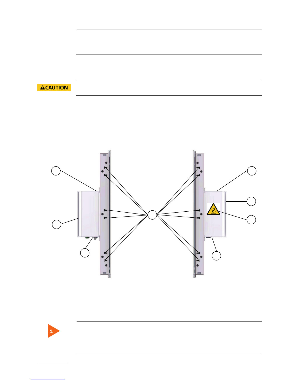
4.4. Bottom Side (with Interfaces)
Figure 11: Bottom side of the FusionClient (interface side; shown as a system with a 15.6" display
Figure 12: Power, control indicators, interfaces
1 Computer base
2 Interfaces on the bottom
side
3 Air openings at the bottom
side of the computer base
(cover with cooling fins)
4 Touch display unit
5 Mounting slots (without installed
mounting clamps and screws)
6 Air openings on the bottom side of
the touch display unit
7 6x screws that secure the front panel
to the cover with cooling fins of the
computer base
5 6 1
6
5
4 3 6 5 5
2
1 2 3 4 5 6 7 8 9
11
12
13
14
15
10
7
Page 34

FusionClient – User Guide (Rev. 1.3)
www.kontron.com // 34
1 DC power input connector (X1)
2 2x Ethernet connector(X2, X3)
3 1x USB 3.0 (X4)
4 2x USB 2.0 (X5, X6)
5 1x serial port COM1, RS232 (X7)
6 1x SD card slot (X8)
7 1x DisplayPort (X9)
8 Power button
9 Storage activity LED
10 Power LED
11 Grounding stud and symbol
12 1x Ethernet connector (X10) (option)
13 1x serial port COM2, RS232, RS422 (X11)
(option)
14 1x serial port COM3, RS485 (X12) (option)
15 Optional interface (X13)
4.4.1. (X1) - DC Power Input Connector
The 3-pin connector (X1, Figure 12, pos. 1 and Figure 13) provides the power connection of the FusionClient
system to an appropriate DC main power supply (15-30 V DC) via a power cable connection (refer to
section 6.1. and 6.1.1.). For pin assignments, refer to subsection 9.1.1.
Figure 13: Detail of the DC Power connector shown without Phoenix terminal
The external cable connector is a Phoenix PSC 1,5/ 3-M, 3-pin plug with an SCT-D-SUB 9-KG housing. This
power plug is delivered with the Fusion Client. The mating connector is a Phoenix PSC 1,5/ 3-F connector.
The system is equipped with a reverse voltage protection (30 V max).
For connection to a DC power supply, refer to subsection 6.2.2.
For connection to an AC power supply by use of the optional AC/DC adapter refer to subsection 6.2.3.
4.4.2. Grounding Stud
There is an M4 grounding stud (Figure 12, pos. 11). Please observe the requirements for grounding and
connect this terminal as required.
Each FusionClient system is equipped with the stud marked with a grounding
symbol (Figure 12, pos. 11) has to be grounded to an appropriate “common earth”
connection point (refer to 6.2.2 “DC Power Connection”.
4.4.3. Controls and Indicators
Figure 14: FusionClient - Controls and Indicators
Pin Signal Name
1 15-30 V DC (input)
2 Shield
3 0 V (input)
Pin 3
1
1
Power Button
2 Power LED
3 Storage activity LED
2
3
Page 35

FusionClient – User Guide (Rev. 1.3)
www.kontron.com // 35
4.4.3.1. Power Button and Power LED
The power button (Figure 12, pos. 8 and Figure 14, pos. 1) allows to power ON/OFF the system. It is located
on the rear side of the device. By pressing the power button for longer than four seconds, a forced
shutdown of the system will be initialized.
Performing a forced shut down can lead to loss of data or other undesirable
effects!
Please note the BIOS setup settings (BIOS Setup/Advanced/South Cluster
Configuration/Miscellaneous Configuration/State after G3 –S0 State). “Power On”
is the default setting. Please also note the description in section 6.4 “System Self
Protection against Ambient Overheating”.
Page 36

FusionClient – User Guide (Rev. 1.3)
www.kontron.com // 36
The power LED (Figure 12, pos. 10 and Figure 14, pos. 3) is on green steady when power is applied to the
system.
Prerequisite:
The FusionClient system has to be connected to an appropriate main power supply (DC).
Even when the system is turned off via the power button, there are parts of the
system still energized.
The unit is completely disconnected from the DC mains only when the power is
removed.
The DC main power supply should be able to be switched off and on via a 2-pole
isolating switch. The unit is only completely disconnected from the DC main power
supply, when the DC power cord is disconnected either from the DC main or the
unit. Therefore, the DC power cord and its connectors must always remain easily
accessible.
As soon as external power is applied to the main input power connector, (X1, Figure 12, pos. 1), the
FusionClient boots up and then starts the operating system and application where available.
To perform an orderly shutdown of the system, press the power button, and the system shuts down
under the control of the operating system.
Once the system has been shut down, it can restarted by pressing power button (assuming that power is
still applied to the main input power connector X1 (Figure 12, pos. 1).
4.4.3.2. Power LED and Storage Activity LED
The power LED (Figure 12, pos. 10) and the storage activity LED (Figure 12, pos. 9) which are located on the
front side of the system indicate the system status.
The power LED (Figure 12, pos. 10) indicates the current system power state (S0, S3, S4, or S5) as shown in
Table 5. The power LED will blink red if an error condition was detected (the system is held off). The color
red is reserved for error state only.
Table 5: Colors of the power LED indicate the system status
System System Status Color of the Power LED
Fusion Client
Power off or PC failure off
System held off (i.e. temperature over 85 C,
etc.)
red
System at high temp (temperature over 80 C)
red*
System in S4/S5
orange
System in S3
orange*
System in S0
green
*) The system power LED blinks with 1Hz (75% duty cycle).
Depending on the system configuration and storage drives activities, the storage activity LED (Figure 12,
pos. 9 and
Figure 14, pos. 3) may be blinking as shown in Table 6.
Table 6: Storage activity LED colors indicate the storage media activity
System Activity of the installed Storage Media Color of the storage activity LED
Page 37

FusionClient – User Guide (Rev. 1.3)
www.kontron.com // 37
FusionClient
No activity on SATA / mSATA / SD-card
off
SATA / mSATA activity
orange
SD-card activity
green
Activity on SD-card has a higher priority than SATA / mSATA.
4.4.4. X2/X3 - Ethernet Connectors
These connectors (X2/X3, Figure 12, pos. 2) are Gigabit Ethernet 10/100/1000 Mb/s, IEEE 1588 capable
interfaces. The connectors are standard 8-pin RJ45 type connectors with status LEDs. These LEDs
indicate the status of the LAN.
Pin# Signal Name J5, J6: LAN1, LAN2 [RJ45 (female)]
1 MDI0+
2 MDI0-
3 MDI1+
4 MDI2+
5 MDI2-
6 MDI1-
7 MDI3+
8 MDI3-
Left LED States Link Activity State Right LED State Link Speed
Off Link not active Off 10 Base-T
Green (constant
on)
Link active Yellow (constant on) 1000 Base-T
Green (flashing) Link active plus
activity
Green (constant on) 100 Base-T
For pin assignment refer to subsection 9.1.6.
4.4.5. X4 - USB 3.0
The FusionClient provides one USB 3.0/2.0 interface. This connector (X4, Figure 12, pos. 3) allows
connection of USB 3.0 or USB 2.0 compatible devices to the system.
For pin assignment, refer to subsection 9.1.5.
4.4.6. X5/X6 - USB 2.0
The FusionClient provides two USB 2.0/1.1 interfaces. These connectors (X5/X6, Figure 12, pos. 4) allow
connection of USB 2.0 or USB 1.1 compatible devices to the system.
For pin assignment, refer to subsection 9.1.4.
right LED
18
left LED
Page 38

FusionClient – User Guide (Rev. 1.3)
www.kontron.com // 38
4.4.7. X7 - RS232 Serial Port (COM1)
The RS232 interface (X7, Figure 12, pos. 5) provided as a 9-pin D-SUB connector, allows you to connect a
serial device to the system.
For pin assignment, refer to subsection 9.1.2.
4.4.8. X8 – SD CARD Slot
This slot, (X8, Figure 12, pos. 6) provided as an SD/SDHC compliant interface is realized using a standard
SD card connector. It is accessible at the bottom side of the FusionClient and is located between the serial
interface (X7, RS232) and DisplayPort (X9). The SD card slot should only be used for service purposes.
This SD card reader supports SD, and SDHC cards.
SD card activity is indicated by the storage activity LED (Figure 12, pos. 9) of the FusionClient.
This interface permits hot-plugging of the SD card. The system can also be booted from this interface.
Page 39

FusionClient – User Guide (Rev. 1.3)
www.kontron.com // 39
Figure 15: FusionClient – SD card slot Figure 16: FusionClient – SD card (not included)
To prevent data loss when removing the SD/SDHC card, it may not be removed
during a read or write access [while the Power LED is “on”; refer to Notice of the
Table 6)].
To install an SD card please perform following steps:
1. Insert the SD/SDHC card into the SDCARD slot (see Figure 12, pos. 6) on the bottom side of the
FusionClient.
2. Gently push the card into the slot until it snaps into place. When the card was inserted correctly, the
storage activity LED (Figure 12, pos. 9) lights up.
Do not act with force when inserting the memory card. If the card is not inserted
properly in the guide rails, remove the card from the slot and re-insert it with care.
3. The card is ready for use.
To remove a card, proceed as described below:
1. Gently push the SD/SDHC card until it clicks.
2. Release the card and it will be partially ejected.
3. Pull the card out from the slot.
4.4.9. X9 - DisplayPort
The DisplayPort (X9, Figure 12, pos. 7) provided as a compliant interface using a standard DisplayPort
connector, allows to connect an external (digital) display to the system. For pin assignment, refer to
subsection 9.1.3.
4.4.10. X10 – Optional Ethernet Connector
This optional connectors (X10, Figure 12, pos. 12) is a Gigabit Ethernet 10/100/1000 Mb/s, IEEE 1588
capable interface. The connectors is a standard, 8-pin RJ45 type connector.
For pin assignment, refer to subsection 9.1.6.
Page 40

FusionClient – User Guide (Rev. 1.3)
www.kontron.com // 40
4.4.11. X 11 – Optional serial Port COM2 (RS232)
The RS232 interface (X 11, Figure 12, pos. 13), if ordered, is provided as a 9-pin D-SUB connector. It allows
you to connect a serial device to the system. For pin assignment, refer to subsection 9.2.1.
Page 41

FusionClient – User Guide (Rev. 1.3)
www.kontron.com // 41
4.4.12. X 12 – Optional serial Port COM3 (RS422/RS485)
The interface (X 12, Figure 12, pos. 14), if ordered can be provided on your FusionClient as an RS422 or
RS485 serial port, 9-pin D-SUB connector (female). This port can be configured corresponding to your
requirements at factory only. For RS422 pin assignment, refer to subsection 9.2.2 and for RS485 refer to
9.2.3 and 9.2.4.
The customized settings for RS485 mode communication allow the system’s operation either in full
duplex mode or in half duplex mode.
4.4.13. X13 - Optional Extension Port (D-Sub Type Connector)
Figure 17: Extension Port for optional interface
If ordered, this D-Sub type extension port (X13, Figure 12, pos. 15) can be configured corresponding to your
requirements at factory only.
4.4.14. Mounting Slots on the bottom Side of the Touch Display Unit 9.2.1
On the bottom side of the touch display unit are available two pairs of mounting slots (Figure 12, pos. 5
and Figure 18, pos. 1) for the installation of the provided mounting clamps with screws (Figure 18, pos. 2).
Figure 18: Bottom side of the touch display unit with installed mounting clamps (enlarged)
1 Pairs of mounting slots
2 Mounting clamp with screw
Note for mounting clamps:
The FC 215 and FC 185 system will be secured into a wall/panel by use of:
four mounting clamps at the top and bottom side
three mounting clamps at the left and right side
The FC 156 system will be secured into a wall/panel by use of:
four mounting clamps at the top and bottom side
two mounting clamps at the left and right side
The optional interface on the bottom side of the FusionClient must
be ordered separately. To add an optional interface to the system,
the second mPCIe socket of the baseboard), will be used. This
connection can be implemented at factory only.
2
1
1
2
Page 42
FusionClient – User Guide (Rev. 1.3)
www.kontron.com // 42
The FC 121 system will be secured into a wall/panel by use of:
two mounting clamps at the top and bottom side
two mounting clamps at the left and right side
4.4.15. Air Openings on the bottom Side of the Touch Display Unit
The air intake openings (Figure 11, pos. 6) are situated on the bottom side of the touch display unit.
When powering on the FusionClient, make sure that the air intake and exhaust
openings are not obstructed.
4.5. Left and Right Side View
On the left and right side of the system are situated mounting slot for installation of the mounting clamps
with screws.
Figure 19: Left side of the FusionClient shown as FC
215
Figure 20: Right side of the FusionClient shown as
FC 215
Legend for
Figure 19
and
Figure 20
:
1 Mounting slots for installing the
mounting clamps with screws
2 Top side of the computer base
3
Cooling fins of the computer base
4 Interface side (bottom)
5 Warning Label “Hot Surface”
Note for mounting clamps:
The FC 215 and FC 185 system will be secured into a wall/panel by use of:
four mounting clamps at the top and bottom side
three mounting clamps at the left and right side
2 2 3 4 3
4
5
1
Page 43

FusionClient – User Guide (Rev. 1.3)
www.kontron.com // 43
The FC 156 system will be secured into a wall/panel by use of:
four mounting clamps at the top and bottom side
two mounting clamps at the left and right side
The FC 121 system will be secured into a wall/panel by use of:
two mounting clamps at the top and bottom side
two mounting clamps at the left and right side
Please observe the warning label “Hot Surface” shown in Figure 20 on the rear left
side of the system. The chassis may be hot during operation and should not be
touched without taking care.
The material on bottom surface of the enclosure interior where the FusionClient is
to be mounted, shall keep at least flammability class UL 94-5VB. Don’t put
flammable materials under the device.
4.6. Top Side
Figure 21: Top side of the FusionClient shown as FC 215
1 Touch display unit
2 Computer base
3 Air openings on the top side of the computer
base
4 Air exhaust openings on the top side pf the
touch display unit
5 Two pairs of mounting slots without installed
mounting clamps and screws
6 6x screws that secures the top panel to the
computer base (cover with cooling fins)
When powering on the FusionClient, make sure that the air intake and exhaust
openings are not obstructed and the cooling fins not covered by objects.
2
3
5 4
5 4 5 4 5
1
6
Page 44

FusionClient – User Guide (Rev. 1.3)
www.kontron.com // 44
Note for mounting clamps:
The FC 215 and FC 185 system will be secured into a wall/panel by use of:
four mounting clamps at the top and bottom side
three mounting clamps at the left and right side
The FC 156 system will be secured into a wall/panel by use of:
four mounting clamps at the top and bottom side
two mounting clamps at the left and right side
The FC 121 system will be secured into a wall/panel by use of:
two mounting clamps at the top and bottom side
two mounting clamps at the left and right side
Page 45

FusionClient – User Guide (Rev. 1.3)
www.kontron.com // 45
4.7. Rear Side
Figure 22: Rear side of the FusionClient shown as FC 215
1 Rear side of the touch display unit
2 Cover of the computer base with cooling fins
3 Screws that secures the cover with cooling
fins to the display unit
4 Gasket location (around the rear side of the
touch display unit)
5 Interface side of the computer base
6 14 x mounting clamps with screws
7 4x M4 threaded blind holes (8mm max) for
mounting of the optional VESA® 75/100
compliant mounting adapter
8 Type label
When powering on the FusionClient, make sure that the air intake and exhaust
openings are not obstructed and the cooling fins not covered by objects.
Please do not remove the screws marked with red in the picture (Figure 22 pos. 8).
Refer to the note for mounting clamps in section 4.5 “Left and Right Side View”.
Please observe the warning label “Hot Surface” shown in Figure 22 on the rear side
of the system. The chassis may be hot during operation and should not be touched
without taking care.
The material on bottom surface of the enclosure interior where the FusionClient is
to be mounted, shall keep at least flammability class UL 94-5VB. Don’t put
1 5 3 3 2
6
6 6 6
4
6
6 6 6
6
6
6
6
6
6
7
8
Page 46

FusionClient – User Guide (Rev. 1.3)
www.kontron.com // 46
flammable materials under the device.
Page 47

FusionClient – User Guide (Rev. 1.3)
www.kontron.com // 47
4.7.1. Gasket on the Rear Side
The gasket (Figure 22, pos. 4).at the rear of the touch display unit has to be present and in proper
condition.
4.7.2. VESA 75/100 Mounting Holes
The FusionClient can be mounted to a VESA 75/100 compliant mounting system (in vertical position with
the interfaces downwards). The FusionClient mounted to a VESA 75/100 compliant mounting system may
be rotated to left or right in order to view landscape or portrait images if the installed operating system
supports this feature. Ensure that the length of the cable connections to power and peripherals are
sufficient for this operating position.
Figure 23: Detail with holes (M4 - depth 8 mm) for VESA 75/100 mounting
4.8. External AC/DC Adapter (Option)
The external AC/DC power adapter is delivered with two main power cords (1x for Europe and 1x for USA)
and a and a custom designed wall mount kit.
Figure 24: Optional AC/DC adapter
For connecting the FusionClient to AC power mains refer to subsection 6.2.3 “AC Power Connection”.
DC power connector
(Connector to the
AC power
Power LED of the
AC/DC adapter
AC/DC adapter
Page 48

FusionClient – User Guide (Rev. 1.3)
www.kontron.com // 48
Page 49

FusionClient – User Guide (Rev. 1.3)
www.kontron.com // 49
5/ Installation Instructions
The FusionClient is designed to be mounted in the user’s application by either of the following methods:
Installation in an instrument panel or other cabinets by use of mounting clamps (preferred mounting
method)
Installation by a heavy duty VESA 75/100 compliant mounting system
The FusionClient has to be installed and operated only by trained and qualified
personnel.
We recommend that the mounting procedure is to be carried-out by two persons.
The mounting and operation of the FusionClient is allowed in horizontal (with the
interfaces downwards) and vertical position. Vertical operating position (with the
interfaces to the left or to the right) is only possible when supported by the OS
used.
The unit must be placed such that there is sufficient space for connecting the cables
to the I/O interface connectors.
Leave at least 5 cm (approx. 2") of free space around the unit to prevent the device
from possibly overheating! Do not obstruct the air intake and exhaust openings.
The voltage feeds must not be overloaded. Adjust the cabling and the external
overload protection to correspond with the rated voltage range indicated on the
type label.
The type label is located on the rear left side of the system.
During the system operation, the cover of the computer base must be proper
installed and secured by the corresponding screws.
5.1. Installation by use of the Mounting Clamps
The mounting clamps with screws (supplied), allow the easy and fast mounting of the FusionClient FC
121/FC 156/
FC 185/FC 215. The outline and mounting drawing can be found on our web site www.kontron.com
.
Table 7: FusionClient - Specification for mounting
Dimensions for: FC 121 FC 156 FC 185 FC 215
Cut-out for mounting to
a wall/panel (W x H)
[mm]
312 x 250 [mm]
(12.28" x 9.84")
398 x 282 [mm]
(15.67" x 11.02")
464 x 321 [mm]
(18.27" x 12.64")
529 x 357 [mm]
(20.83" x 14.06")
Thickness of the
mounting wall/panel
for proper mounting
[mm]
1.5 - 6
Clamp with screws for
mounting the
FusionClient to a
wall/panel
8x 12x 14x
Required Tool Allen Wrench 2 mm
Proper Torque
Tighten the screws with a torque of 0.7 Nm (start with 0.4 Nm and increase to 0.7
Page 50

FusionClient – User Guide (Rev. 1.3)
www.kontron.com // 50
Nm)
Mounting position Ensure the vertical and horizontal alignment of the system/display unit.
Refer to the note for mounting clamps in section 4.5 “Left and Right Side View”.
Page 51

FusionClient – User Guide (Rev. 1.3)
www.kontron.com // 51
In order to ensure IP65 front sealing against dust and water,
mount the system on
a non-textured surface.
Before you install the FusionClient system into a panel or a wall, verify the perfect
condition of the gasket at the rear of the front bezel.
The gasket has to be in place without surface imperfections/defects and dirt.
Ensure the vertical and horizontal alignment of the system/display unit.
Figure 25: Wall/panel cutout dimensions for FusionClient systems
The glass front of the FusionClient is fragile. Handle with care to prevent personal
injury or material damage. Never place the FusionClient on the edges or corners of
the glass front. Always use two hands when carrying the device.
The glass front of the FusionClient is provided with edge protection and a
protective foil. Only remove this protective material after the installation of the
FusionClient.
248 mm / 9.76 inch
312 mm / 12.28 inch
282 mm / 11.1 inch
398
mm / 15.67 inch
321 mm / 12.64 inch
464 mm / 18.27 inch
357 mm / 14.06 inch
529 mm / 20.83 inch
Wall/panel cut
out
for FC 121
Wall/panel cut
out
for FC 156
Wall/panel cut
out
for FC 185
Wall/panel cut
out
for FC 215
250 mm / 9.84 inch
Page 52

FusionClient – User Guide (Rev. 1.3)
www.kontron.com // 52
Figure 26: Wall/panel mounting of the FusionClient by use of the mounting clamps
1 Front panel of the FusionClient with
gasket
2 Touch display unit
3 Bottom side of the computer base
4 Mounting clamps with screws for system
installation into a wall/panel
5 Example of wall for system installation (with
specified max. wall thickness)
To mount the system to a wall or to a panel, follow these steps:
1.
Depending on the dimension of the display enclosure of your FusionClient, prepare a cutout in the
wall/panel. The maximum thickness of the wall/panel is 6 mm. Refer to Table 7 and Figure 25 for the
wall/panel cutout dimensions or to the corresponding mechanical drawings for your FusionClient on
our web site
www.kontron.com.
2.
The system must be properly powered down and disconnected from the power source and
peripherals.
3.
The wall/panel where you intend to install the system must be accessible from both sides (front as
well as rear). The material strength and stiffness must be sufficient to hold the fusion client unit.
4.
Insert the system into the wall/panel cutout from the front.
5.
In order to ensure the protection class IP65 on the front side in the installed condition, the contact
surface with the gasket must be clean and flush.
6.
Hook the mounting clamps with screws (Table 7) from the rear side of the panel into the
corresponding pairs of slots as shown in Figure 18. Refer also to Figure 19 and Figure 20 pos. 1, and
Figure 21, pos. 4) of the touch display unit enclosure.
7.
The system must be attached firmly by tightening the screws (refer to Figure 26, pos. 4 and Figure 18,
pos. 2). Refer also to the mounting requirements included in Table 7. Always tighten screws in pairs
on opposite sides of the front panel. Repeat the tightening sequence two times and increase the
torque from 0.4 to 0.7 Nm.
4
2 1 5
Max. wall/
panel
thickness
4
3
Page 53

FusionClient – User Guide (Rev. 1.3)
www.kontron.com // 53
6/ Starting Up
6.1. DC Power Terminal
The FusionClient is delivered with a DC power plug terminal (3-pin Phoenix connector). For DC connection,
prepare the connecting wires using the supplied Phoenix plug terminal: PSC 1,5/ 3-F.
Figure 27: Phoenix power plug terminal
1 3-pin Phoenix plug terminal
2 Cover over the slotted pan head screws
3 Location for inserting the "15-30 V DC
input" wire
4 Location for inserting the
“shield” wire
5 Location for inserting the “0 V
(input)” wire
6.1.1. Cabling
For the pin assignment Phoenix power plug terminal refer to subsection 9.1.1 “(X1) Power Input
Connector”.
1.
Cut the required length three isolated wires (1 mm
2
) AWG18 and strip each end 5 –7 mm.
2.
Twist the striped wire-ends and provide them with ferrules.
3.
Open the cover (Figure 27, pos. 2) to have access to the slotted pan head screws.
4.
Loosen the slotted pan head screws of the DC plug terminal far enough so that you can insert the end
of the prepared wires.
5.
Insert the wires into the corresponding clamp of the Phoenix plug terminal. Make sure that you have
the right polarity of the connection [refer to Figure 27, Figure 13 or subsection 9.1.1 “(X1) Power Input
Connector”].
6.
Fasten the screws to secure the wires into the clamps of the plug terminal.
7.
Close the cover (Figure 27, pos. 2).
3 2 1 4 5
Page 54

FusionClient – User Guide (Rev. 1.3)
www.kontron.com // 54
6.2. Connecting to Power
Before using your system, you should first become familiar with the system
components and check that everything is properly connected. Following a proper
cabling procedure will prevent a false power-on condition, which could result in
unit operational failure.
The rated voltage range of the mains supply must correspond to the value on the
type label.
The FusionClient systems can be connected to a DC power source or optionally via an AC /DC powe
adapter to an AC main power. The DC power connector (Figure 12, pos. 1) is located on the bottom side of
the system.
6.2.1. Behavior of the System when Connecting to Power
As soon as external power is applied to the input power connector (refer to Figure
12, pos. 1 and Figure 13) the FusionClient boots up and the operating system and
applications, where available, start immediately. Refer to 4.4.3.1 “Power Button
and Power LED”.
6.2.2. DC Power Connection
Please observe the safety requirements given in chapter 1/ “General Safety Instructions for IT Equipment”.
The system must be connected only to a LPS (Limited Power Supply) DC mains
power supply complying with the requirements of EN 60950-1.
It must be ensured that the system can be powered ON and OFF via a readily
accessible two-pole disconnecting device that shall be incorporated in the building
installation wiring. It must be UL-listed and correspond to the required current and
voltage for the FusionClient (refer to the type label).
The system is only completely disconnected from the DC power source, when the
DC power cord is disconnected either from the power source or the unit. Therefore,
the DC power cord and its connectors must always remain easily accessible.
Ensure that a short-circuit (overcurrent) protection, is provided as part of the
building installation. Install only in accordance with national and local wiring
regulations.
When you install or replace the system the ground connection must always be
made first and disconnected last.
We recommend that the power cable should be the last cable attached to the
system.
To connect the FusionClient to a corresponding DC main power supply, please perform the following
steps:
1.
The wires used for power connections must be clearly marked (+/-/grounding) to ensure that they
will be proper connected to the DC connector of the FusionClient and to the main power source,
corresponding the signals marked (refer to Figure 13).
Page 55

FusionClient – User Guide (Rev. 1.3)
www.kontron.com // 55
2.
Ensure that the DC power source is switched off via a disconnecting device (circuit breaker), in order
to ensure that no power is flowing from the external DC power source during the connection
procedure.
3.
Connect at first the wire for the grounding stud” (Figure 12, pos. 11) to an appropriate “common earth”
connection point.
4.
Connect the Phoenix power terminal prepared as described in subsection 6.1.1 ”Cabling” to the DC
input connector (Figure 12, pos. 1, marked X1) of the FusionClient. The DC input connector is located on
the front side and is marked “24 VDC”.
5.
Connect the other ends of the DC power wires to the connections of the DC main power supply. Pay
attention to the polarity of the connections.
6.
Switch on the disconnecting device (circuit breaker) in order to apply voltage to the terminals of the
power wires.
Page 56

FusionClient – User Guide (Rev. 1.3)
www.kontron.com // 56
6.2.3. AC Power Connection
Please observe the safety requirements given in chapter 1/ “General Safety Instructions for IT Equipment”.
Use only a LPS (Limited Power Supply) power supply complying with the
requirements of
EN-60950-1 to connect the system to an AC power source.
The AC power cable must correspond to the requirements of the country where the
system is used.
Make sure that the mains power supply (power outlet) is properly grounded and
that the power cord is in perfect condition without any visible damage. An
ungrounded power supply is not permissible.
The AC power cable of the AC/DC adapter is the disconnecting device. For this
reason the socket for the power supply must always be mounted close to the
device and be easily accessible.
The FusionClient system will be connected to an AC power source via the optional AC/DC adapter (refer to
Figure 24).
1.
Connect the 3-pin DC connector of the AC/DC adapter to the appropriate DC power connector (Figure
12, pos. 1) of the FusionClient. The DC power connector of the system is located on the bottom side
and is labeled “15-30V DC”. Make sure the connector is securely locked in place.
2.
Connect the AC power cord to the AC/DC adapter.
3.
Plug the AC connector of the adapter into an AC wall outlet of the AC power source.
Page 57

FusionClient – User Guide (Rev. 1.3)
www.kontron.com // 57
6.3. Operating System and Hardware Component Drivers
Your system can be supplied optionally with a pre-installed operating system.
If you have ordered your FusionClient with a pre-installed operating system, all drivers are installed in
accordance with the system configuration ordered (optional hardware components). Your system is fully
operational when you power it on for the first time.
If you have ordered the FusionClient without a pre-installed operating system, you will need to install the
operating system and the appropriate drivers for the system configuration you have ordered (optional
hardware components) yourself.
You can download the relevant drivers for the installed hardware from our web
site at www.kontron.com
by selecting the product.
Pay attention to the manufacturer specifications of the operating system and the
integrated hardware components.
6.4. System Self Protection against Ambient Overheating
The FusionClient system is designed to be protected against ambient overheating.
During operation the system will initialize automatic shutdown (emulation of short press of the power
botton, if the internal temperature reaches the limit of 83°C (measured on the internal temperature
sensor). This could happen if the ambient temperature around the system exceeds (e.g. because of
external reasons) the maximum specified ambient temperature of 50°C. In case that the internal
temperature reaches limit of 85°C (measured on the internal temperature sensor), the system will
perform an emergency turn off. In case of emergency turn off the running applications will not be closed
properly (because of the device’s turn off).
What happens after such automatic shutdown or emergency turn off?
The system should cool down until the internal temperature decrease below: 80°C.
The FusionClient system turns on automatically and performs a system start as soon as the internal
temperature decreases to 80 °C.
Please observe that as long as the internal temperature is too high:
the color of the power LED (Figure 12, pos. 10 and Figure 14, pos. 2) on the bottom side of the system
indicates the current power state and signalizes the emergency state of the system (refer to
subsection 4.4.3.2 “Table 5”).
Please observe that as long as the internal temperature is too high, the color of
this LED stays permanently red.
the function of the power buttons is deactivated.
the settings in BIOS Setup/Advanced/South Cluster Configuration/Miscellaneous Configuration/State
after G3 –S0 State with option settings: Power on (default)/ Power off) will also be ignored.
When the system is turned off via the self protection against ambient overheating
function, any unsaved data will be lost. [The system is powered off immediately
(like a “forced off” via power button) and enter into 5-volt standby mode as long as
the internal temperature is too high.]
Page 58

FusionClient – User Guide (Rev. 1.3)
www.kontron.com // 58
Page 59

FusionClient – User Guide (Rev. 1.3)
www.kontron.com // 59
7/ Maintenance and Cleaning
Kontron systems require minimal maintenance and care to keep them operating correctly.
Occasionally wipe the FusionClient with a soft dry microfiber cloth.
You should only remove persistent dirt by use of a soft, slightly damp cloth and mild detergent.
7.1. Touch Screen Care and Cleaning
The touch screen is covered by an anti-glare glass plate and care should be taken
when cleaning it. The front side of the touch display unit is sealed against dust and
liquids.
The touch screen is protected by an anti-glare glass surface. Care should be taken to avoid using sharp
objects such as knife, pen or pencil tips. Sharp objects may permanently damage the surface of the antiglare glass plate.
Mild detergent and water is recommended for cleaning the touch screen. Use of strong solvents must be
avoided. Wet the glass plate with a microfiber cloth lightly moistened with warm water and mild glass
cleaner.
7.2. Replacing the Lithium Battery
The lithium battery is located on the installed carrier board and is not a serviceable
part. Please contact Kontron support if the lithium battery needs to be replaced.
Page 60

FusionClient – User Guide (Rev. 1.3)
www.kontron.com // 60
8/ Technical Data
System FC 121 FC 156 FC185 FC215
TFT LCD Display
Size (diagonal) 12.1" 15.6" 18.5" 21.5"
Active area
(H x V) [mm]
261.1 x 163.2 344.2 x 193.5 409.8 x 230.4 476.6 x 268.1
Resolution
(H x V) [pixel]
1280 x 800 1366 x 768 (HD) 1366 x 768 (HD) 1920 x 1080
(Full HD)
Pixel Pitch
(H x V) [
µ
m]
204 x204 252 x 252 300 x 300 248 x 248
Colour Depth
16.7M colors
16.7 M colors
16.7 M colors
16.7 M colors
Backlight
LED
LED
LED
LED
Brightness
[cd/m2]
400 400 450 300
Control Signal
24 bit/s LVDS
24 bit LVDS
24 bit LVDS
24bit LVDS
Viewing Angle
[°]
(r / l / u / d)
88/88/88/88 85/85/80/80 85/85/80/80 89/89/89/89
Contrast ratio 1000:1 500:1 1000:1 5000:1
Response Time
[msec]
10 8 5 25
Touch Screen
Projected
Capacitive
Projected
Capacitive
Projected
Capacitive
Projected
Capacitive
Installed COM Express
Module and Baseboard
Baseboard with COM Express®-cBTi6 module
Processor
Intel® Atom E3815/E3825/E3826/E3827/E3845
Memory
Depending on the installed CPU:
Up to 2x 204-pin SODIMM dual-channel DDR3L-1600 max. up to 16 GB
BIOS
Phoenix uEFI
External Interfaces
(bottom side
accessible)
2x USB (2.0)
1x USB (3.0)
2x LAN (10/100/1000 Mbps)
1x DisplayPort
1x SD card slot
1x serial port (RS232)
Optional interfaces
(bottom side
accessible)
1x LAN (10/100/1000 Mbps)
1x serial port (RS232)
1x serial port (RS422/RS485 (galvanic isolated)
Operating element
(on the bottom side)
Power button
LED Indicators
(on the bottom side)
Power LED
Storage activity LED
DC IN Power Plug
(on the bottom side)
3 pin Phoenix connector On the bottom side
Power DC: external 15-30 V power source (limited power source)
Page 61

FusionClient – User Guide (Rev. 1.3)
www.kontron.com // 61
AC: via the optional external AC/DC adapter (limited power source) not
included
Lithium Battery (option)
Type: CR2032; 3.0 V; 0.22Ah;
VESA 75/100
On the rear
Protection Class
IP20 rear
IP65 front (only mounted to a wall/panel)
The table is continued on the next page.
Page 62

FusionClient – User Guide (Rev. 1.3)
www.kontron.com // 62
Options
Internal Drives
1x 2.5" SATA SSD
1x mSATA SSD (full size, half size
RFID IDS-R13MP HF/13.56MHz ISO15693
WiFi 802.11a, 802.11b, 802.11g, 802.11n
Serial interfaces 2x DB punch out for1x RS232 and 1x galvanic isolated RS422/RS485
FieldBus
Via internal mPCIe card (full size, half size)
8.1. Electrical Specifications
Hint for DC power connection:
The FusionClient must be connected only to a LPS (Limited Power Supply) DC mains
power supply complying with the requirements of EN 60950-1.
Hint for AC power connection:
Use only a LPS (Limited Power Supply) power supply complying with the
requirements of EN 60950-1 to connect the FusionClient to an AC power source.
FusionClient FC 121 FC 156 FC 185 FC 215
Power 15-30 V DC
Power consumption 3.0 A max. 3.0 A max. 3.5 A max. 3.5 A max.
Page 63

FusionClient – User Guide (Rev. 1.3)
www.kontron.com // 63
8.2. Mechanical Specifications
For detailed mechanical dimensions, please see the outline dimensions drawings on the web site
www.kontron.com
.
FusionClient FC 121 FC 156 FC 185 FC 215
Height 266 mm (10.47") 298 mm (11.73") 337 mm (13.27") 373 mm (14.69")
Width 328 mm (12.91") 414 mm (16.3") 480 mm (18.9") 545 mm (21.46")
Depth (total) 97.1 mm (3.82") 97.1 mm (3.82") 97.1 mm (3.82") 97.1 mm (3.82")
Depth (without
front plate)
89.5 mm (3.52") 89.5 mm (3.52") 89.5 mm (3.52") 89.5 mm (3.52")
Weight 5.0 kg (11.02 lbs) 5.9 kg (13.00 lbs) 8.3 kg (18.29 lbs) 9.5 kg (20.94 lbs)
Display unit Aluminum plate
Chassis
(computer base
cover)
Aluminum with fins and holes for VESA75/100 mounting
Dimension of the touch display unit
FusionClient FC 121 FC 156 FC 185 FC 215
Aluminum front
bezel (W x H)
328 x 266 [mm]
(12.91" x 10.47")
414 x 298 [mm]
(16.3" x 11.73")
480 x 337 [mm]
(18.9" x 13.27")
545 x 373 [mm]
(21.46" x 14.69")
Frontal cut out for
display (W x H)
261.1 x 163.2 [mm]
(10.28" x 6.43")
344.2 x 193.5
[mm] (13.55" x
7.62")
409.8 x 230.4
mm] (16.13" x
9.07")
476.6 x 268.1
[mm] (18.76" x
10.56")
Wall/panel
mounting cut out
(W x H)
312 x 250 [mm]
(12.28" x 9.84")
398 x 282 [mm]
(15.67" x 11.02")
464 x 321 [mm]
(18.27" x 12.64")
529 x 357 [mm]
(20.83" x 14.06")
Page 64

FusionClient – User Guide (Rev. 1.3)
www.kontron.com // 64
Figure 28: Mechanical specification - Front view of the FC 121
Figure 29: Mechanical specification - Rear view of the FC 121
Page 65
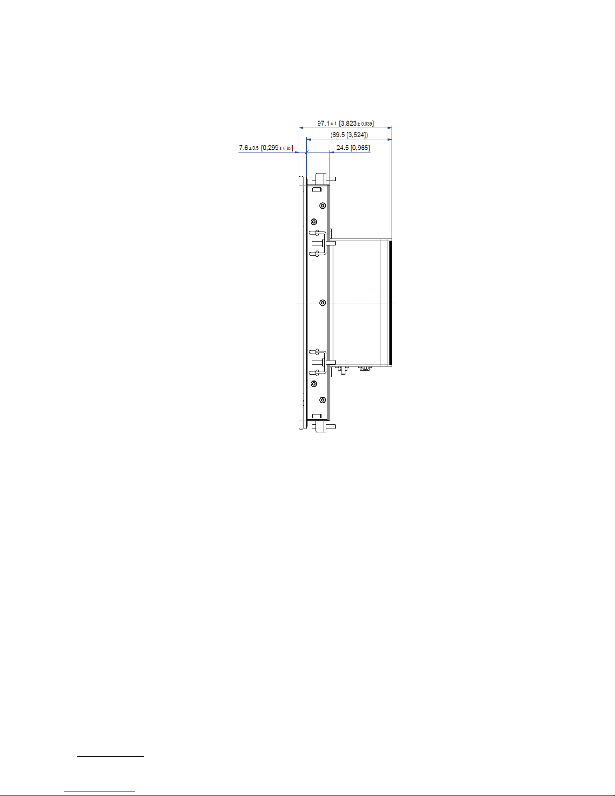
FusionClient – User Guide (Rev. 1.3)
www.kontron.com // 65
Figure 30: Mechanical specification - Side view of the FC 121
Page 66

FusionClient – User Guide (Rev. 1.3)
www.kontron.com // 66
Figure 31: Mechanical specification - Front view of the FC 156
Figure 32: Mechanical specification - Rear view of the FC 156
Page 67
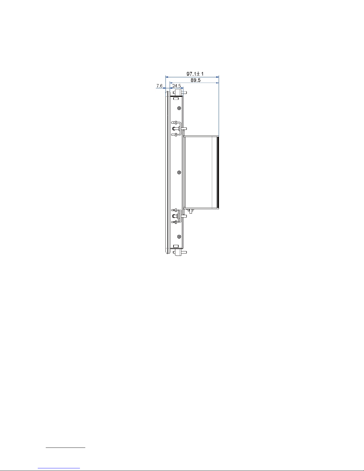
FusionClient – User Guide (Rev. 1.3)
www.kontron.com // 67
Figure 33: Mechanical specification - Side view of the FC 156
Page 68

FusionClient – User Guide (Rev. 1.3)
www.kontron.com // 68
Figure 34: Mechanical specification - Front view of the FC 185
Figure 35: Mechanical specification - Rear view of the FC 185
Page 69
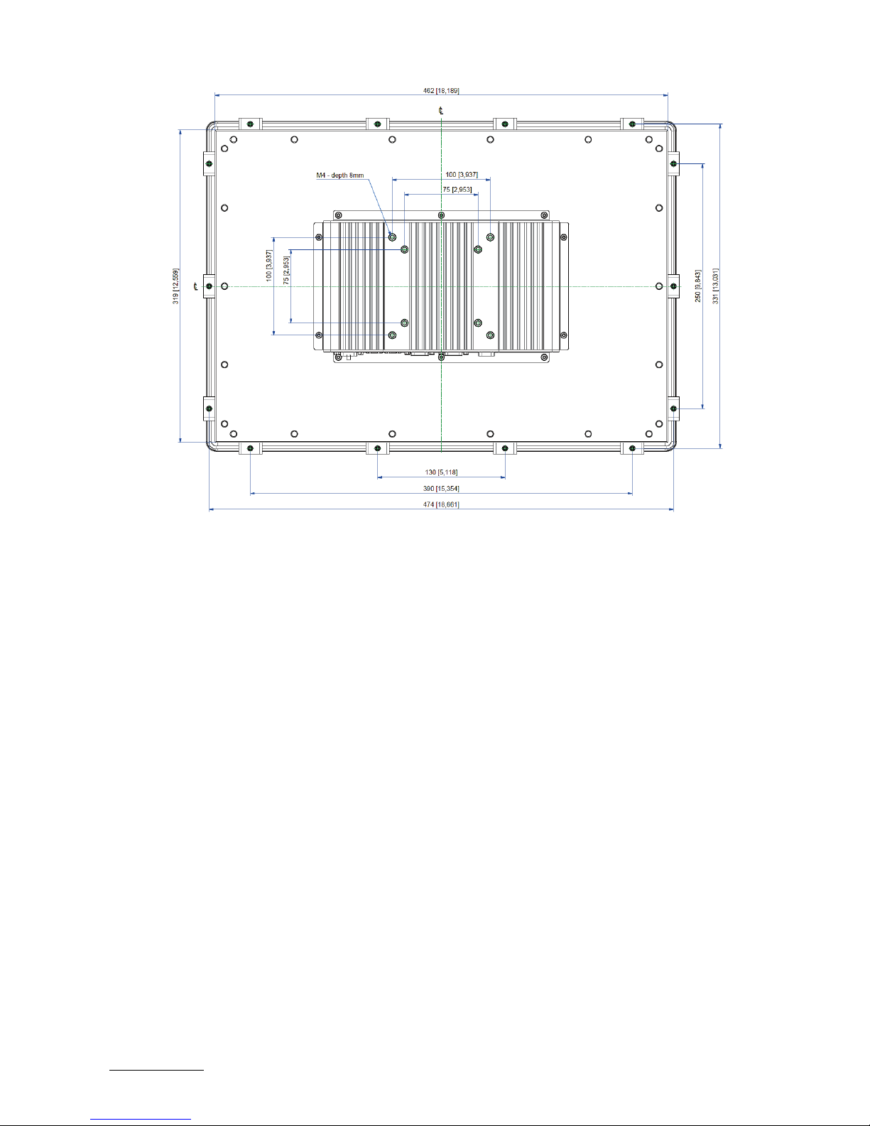
FusionClient – User Guide (Rev. 1.3)
www.kontron.com // 69
Figure 36: Mechanical specification - Side view of the FC 185
Page 70

FusionClient – User Guide (Rev. 1.3)
www.kontron.com // 70
Page 71

FusionClient – User Guide (Rev. 1.3)
www.kontron.com // 71
Figure 37: Mechanical specification - Front view of the FC 215
Figure 38: Mechanical specification - Rear view of the FC 215
Page 72

FusionClient – User Guide (Rev. 1.3)
www.kontron.com // 72
Figure 39: Mechanical specification - Side view of the FC 215
Page 73

FusionClient – User Guide (Rev. 1.3)
www.kontron.com // 73
8.3. Environmental Specifications
Environmental Specifications FusionClient
Thermal management Convection cooling (fanless)
Temperature (operating) 0 °C to +50 °C (32 °F to 122 °F)
Temperature (storage/transit)
-20 °C to +70 °C (-4 °F to 158 °F)
Relative humidity (non operating) 93 % @ 40 °C (non condensing) acc. to IEC 60068-2-78
Shock (operating) 15 G, 11 ms, half sine, acc. to IEC 60068-2-27:2010-2
Shock (non operating) 30 G, 11 ms, half sine, acc. to IEC 60068-2-27:2010-2
Vibration (operating ) 10 Hz to 500 Hz, 1G/3axes acc. to IEC 60068-2-6:2008-10
Vibration (non operating ) 10 Hz to 500 Hz, 2G/3axes acc. to IEC 60068-2-6:2008-10
Max. operation altitude 3,000 m (9842,52 ft.)
Max. storage/transit altitude
4,572 m (15,000 ft.)
Page 74

FusionClient – User Guide (Rev. 1.3)
www.kontron.com // 74
8.4. CE-Directives, Standards and Approvals
CE Directive
Elektrical Safety
General Product Safety Directive (GPSD) 2001/95/EC
Low Voltage Directive (LVD) 2014/35/EU
Electromagnetic
Compatibility (EMC)
EMC Directive 2014/30/EU
RED Directive 2014/53/EU
CE Marking CE Directive 93/68/EEC
RoHS II Directives 2011/65/EU
Elektrical Safety Harmonized Standards
EUROPE
Information technology equipment - Safety - Part 1: General requirements EN
60950-1
U.S.A. / Canada
Certified to IEC/UL 60950-1 + CAN/CSA C22.2 No. 60950-1
CB Report
IEC 60950-1(ed.2);am1, am2
EMC Harmonised Standards
EU
Generic standards - Emission standard for residential, commercial and lightindustrial environments (Emission):
EN 61000-6-3; EN 301 489-17; EN 301 489-1
EN 55011, EN 55022: Class B (Radiated and Conducted Emissions)
Generic standards - Immunity for industrial environments (Immunity): EN 61000-
6-2; EN 301 489-17; EN 301 489-1
U.S.A. / Canada FCC (CFR) 47 Part 15 Subpart B Class B
8.5. WiFi Specification (Option)
WiFi Specification
IEEE WLAN Standard 802.11a, 802.11b, 802.11g, 802.11n
Interface USB 2.0
Antenna 2T2R
8.6. RFID Specification (Option)
RFID Specification
RFID Reader IDS-R13MP HF/13.56MHz ISO15693
Internal antenna Internal connected
Read distance (d Peak) 0-20 mm
Page 75

FusionClient – User Guide (Rev. 1.3)
www.kontron.com // 75
9/ Standard Interfaces – Pin Assignments
Low-active signals are indicated by a minus sign.
9.1.1. (X1) Power Input Connector
Pin Signal Name 3-pin POWER SUBCON (male)
1 15-30 V DC (input)
2 Shield
3 0 V (input)
9.1.2. (X7) COM1 Serial Interface RS232
Pin Signal Name 9-pin D-SUB Connector
1 DCD (Data Carrier Detect)
2 RXD (Receive Data)
3 TXD (Transmit Data)
4 DTR (Data Terminal Ready)
5 GND (Signal Ground)
6 DSR (Data Set Ready)
7 RTS (Request to Send)
8 CTS (Clear to Send)
9 RI (Ring Indicator)
9.1.3. (X8) DisplayPort
Pin Signal Name DisplayPort Signal Name Pin
1 ML Lane 0 (p)
GND (ML Lane 0) 2
3 ML Lane 0 (n) Lane 1 (p) 4
5 GND (ML Lane 1) Lane 1 (n) 6
7 Lane 2 (p) GND (ML Lane 2) 8
9 Lane 2 (n) Lane 3 (p) 10
11 GND (ML Lane 3) Lane 3 (n) 12
13 AUX SEL# Pull-down to GND 14
15 AUX CH (p) GND (AUX CH) 16
17 AUX CH (n) Hot Plug 18
19 GND (GND_DDC)
3.3V (DDC EEPROM
power
500 mA fused
20
Page 76

FusionClient – User Guide (Rev. 1.3)
www.kontron.com // 76
9.1.4. USB 2.0 Port (X5, X6)
Pin
Signal Name
4-pin USB Connector
Typ A Version 2.0
1 VCC used (900 mA max.)
2
Data-
3 Data+
4
GND (ground for power return)
9.1.5. USB3.0 Port (X3)
Pin Signal Name 9-pin USB Connector
Type A Version 3.0/2.0
USB 2.0 contact pins
USB 3.0 contact pins
1 VCC, fused (900 mA max.) 5 StdA_SSRX-
2 Data- 6 StdA_SSRX+
3 Data+ 7 GND_DRAIN
4 GND (ground for power
return)
8 StdA_SSTX-
9 StdA_SSTX+
9.1.6. Ethernet Connectors (X2, X3, X10)
Pin# Signal Name X2, X3, X10LAN1, LAN2,LAN3 (RJ45)
1 MDI0+
2 MDI0-
3 MDI1+
4 MDI2+
5 MDI2-
6 MDI1-
7 MDI3+
8 MDI3-
18
Page 77

FusionClient – User Guide (Rev. 1.3)
www.kontron.com // 77
9.2. Optional Interfaces
These ports (X12 and X13) must be only factory installed and configured.
When you order the FusionClient with this extended interface via
RS485/RS422adapter module, you have to specify in your ordering:
the needed configuration of this port as RS485 or RS422 and
for RS422/RS485 configuration: if the onboard termination resistor (120 Ω)
should be enabled or disabled.
9.2.1. (X 11) Serial Port RS232
Pin Signal Name 9-pin D-SUB Plug (male)
1 DCD (Data Carrier Detect)
2 RXD (Receive Data)
3 TXD (Transmit Data)
4 DTR (Data Terminal Ready)
5 GND (Signal Ground)
6 DSR (Data Set Ready)
7 RTS (Request to Send)
8 CTS (Clear to Send)
9 RI (Ring Indicator)
9.2.2. (X12) Serial Port (RS422/RS485) configured as RS422 (4-Channel Mode)
Pin Signal Name 9-pin D-SUB Plug (female)
1 TxD- (Transmit Data-)
2 RxD+ (Receive Data+)
3 TxD+ (Transmit Data+)
4 RxD- (Receive Data-)
5 GND (Signal Ground)
6 RTS- (Request to Send-)
7 RTS+ (Request to Send+)
8 CTS+ (Clear to Send+)
9 CTS- (Clear to Send-)
,
Page 78

FusionClient – User Guide (Rev. 1.3)
www.kontron.com // 78
9.2.3. (X12) Serial Port (RS422/RS485) configured as RS485 (4-Wire Mode), full duplex,
(Bus-Master)
Pin Signal Name 9-pin D-SUB Plug (female)
1 TxD- (Transmit Data-)
2 RxD+ (Receive Data+)
3 TxD+ (Transmit Data+)
4 RxD- (Receive Data-)
5 GND (Signal Ground)
6 NC
7 NC
8 NC
9 NC
9.2.4. (X12) Serial Port (RS422/RS485) configured as RS485 (2-Wire Mode), half duplex
Pin Signal Name 9-pin D-SUB Plug (female)
1 Data-
2 NC
3 Data+
4 NC
5 GND (Signal Ground)
6 NC
7 NC
8 NC
9 NC
Page 79

FusionClient – User Guide (Rev. 1.3)
www.kontron.com // 79
10/ Technical Support
For technical assistance, please contact our Technical Support department via:
e-mail: support@kontron.com
or
web: http://www.kontron.com/support-and-services
Ensure that your request contains the following information:
unit part number (PN),
serial number (SN), which can be found on the type label,
a short description of the faulty behaviour of your system.
For information about Kontron products and services, please visit www.kontron.com
10.1. Returning Defective Merchandise
Please follow these steps before you return any merchandise to Kontron:
1. Download the corresponding form for returning a device with an RMA No. [RMA (Return of Material
Authorization)] from our website
http://www.kontron.com/support-and-services/support/RMAinformation contact our customer department to obtain an RMA No.
e-mail: service@kontron.com
2. Ensure that you have received an RMA number from Kontron Customer Services before returning any
device. Write this number clearly on the outside of the package.
3. Describe the fault that has occurred.
4. Please provide the name and telephone number of a person we can contact to obtain more
information, where necessary. Where possible, please enclose all the necessary customs documents
and invoices.
5. When returning a device:
Pack it securely in its original packaging.
Enclose a copy of the RMA form with the consignment.
Page 80

FusionClient – User Guide (Rev. 1.3)
www.kontron.com // 80
Global Headquarters
Kontron
S&T AG
Lise
-Meitner-Str. 3-5
86156 Augsburg
Germany
Tel.: +
49 821 4086-0
Fax: +
49 821 4086-111
info@kontron.com
About Kontron
Kontron is a global leader in embedded computing technology (ECT). As a part of technology group S&T
Kontron offers a combined portfolio of secure hardware, middleware and services for Internet of Thing
(IoT) and Industry 4.0 applications. With its standard products and tailor-
made solutions based on highl
reliable state-of-the-
art embedded technologies, Kontron provides secure and innovative applications fo
a variety of industries. As a result, customers benefit from accelerated time-to-market, reduced
total cos
of ownership, product longevity and the best fully integrated applications overall. For more information
please visit:
www.kontron.com
 Loading...