

Page 1

FlexPAC™
Portable Add-In Computer
Document Revision 1.0
Page 2

About this Product
The FlexPAC Portable Add-In Computer is sold by Kontron America’s Mobile Rugged
Division (formerly Dolch Computer Systems.)
About This Manual
This document provides information about the FlexPAC Portable Add-In Computer.
No warranty of suitability, purpose, or fitness is implied. While every attempt has
been made to ensure that the information in this document is accurate, the
information contained within is supplied “as-is” and can change without notice.
Trademarks
FlexPAC is a trademark of Kontron America’s Mobile Rugged Division. All other
product names are trademarks or registered trademarks of their respective holders.
Copyright Notice
Copyright © 2006 Kontron America Mobile Rugged Division.
All rights reserved. No part of this manual may be reproduced, transmitted,
transcribed, stored in a retrieval system, or translated into any language or
computer language, in any form or by any means (electronic, mechanical,
photocopying, recording, or otherwise), without the written permission of Kontron
America Mobile Rugged Division.
Standards
Kontron America is certified to ISO 9001:2000 & AS9100:2004 standards.
Page 3

Technical Support
If you are unable to obtain proper use of your FlexPAC, contact Kontron America
Mobile Rugged Division for technical support. To ensure the most efficient technical
support, be prepared to operate your system while discussing the problem with a
technical support representative. Kontron America Mobile Rugged Division
products can be serviced at any of our worldwide Certified Repair Centers. Contact
Kontron America Mobile Rugged Division technical support for the locations.
Technical support lines are available as follows:
You can contact technical support, Monday through Friday, 7:30 am to 5:00 pm,
Pacific Standard Time (excluding holidays).
Kontron America Mobile Rugged Division
Toll Free 1.800.995.7579
Telephone 1.510.661.2220
Fax 1.510.490.2360
E-mail support@kontronmrd.com
If you have technical questions or need assistance in identifying or solving a
problem, the technical support department can assist you with your problems and
provide you with the technical information you require. To ensure the most efficient
technical support, please be prepared to operate your system while discussing the
problem with a technical support representative.
When you call technical support please have the following information ready:
h Serial number of your system
h Model name of your system
h Type and version of your operating system
h Type and version of your software program
h Peripheral devices connected to your system
h What messages, if any, are on the screen
Page 4

Customer Support
The Kontron America Mobile Rugged Division customer service department will
provide assistance for most of your non-technical needs. To obtain upgrade
quotations, purchase replacement or spare parts, extended warranties and RMA
status, you e-mail us at support@us.kontron.com or visit www.kontron.com.
Return Instructions
If you need to ship your unit back to Kontron for service or repair, please contact
technical support for a Return Material Authorization (RMA) number. Have your
serial number available and the reason for the return when requesting a RMA
number. Kontron products can also be serviced at our worldwide Certified Repair
Centers. Contact Kontron technical support for the locations.
You can also request a RMA number by visiting our Web site at www.kontron.com.
Please contact Kontron America Mobile Rugged Division customer service prior to
shipping any unit back to Kontron America Mobile Rugged Division for service.
Should it be confirmed by service that it is necessary to return your unit back to
Kontron America Mobile Rugged Division for servicing, please pack your unit in the
original shipping container. If the original shipping container is no longer
available, the unit must be securely packed to prevent damage during shipment.
You must obtain a RMA number from customer service prior to shipment. The serial
number of your unit and the RMA number must accompany the returned unit.
Limited Warranty
Kontron America Mobile Rugged Division warrants this product against any defects
in material or workmanship, providing the serial number appears on the product
and it is originally configured by the factory.
Terms of the Limited Warranty is as follows:
1. Labor Charges: For a period of two (2) years from the date of original purchase,
there will be no labor charges for repairing the defective product. For confirmation
of warranty and registration of product, please complete the Warranty Registration
Card for your FlexPAC and return it to Kontron America Mobile Rugged Division.
2. Charges for Replacement Parts: For a period of two (2) years from the date of
purchase, Kontron America Mobile Rugged Division will supply, at no charge, new
or rebuilt replacement parts for any defective parts. If failure of the product has
resulted from accident, abuse or misapplication Kontron America Mobile Rugged
Division shall have no responsibility under this Limited Warranty.
Purchaser’s Exclusive Remedies During the warranty period, your exclusive remedy
for a defective product is the repair or replacement, at Kontron America Mobile
Rugged Division’s option, of the defective part.
KONTRON AMERICA MOBILE RUGGED DIVISION’S LIABILITY TO YOU, THE ORIGINAL
PURCHASER, FOR ANY CLAIM, LOSS, DAMAGE OR EXPENSES OF ANY KIND,
Page 5

(INCLUDING ATTORNEY’S FEES), RESULTING FROM OR IN CONNECTION WITH, GOODS
OR ANY DEFECT, REPAIR, REPLACEMENT, NEGLIGENCE OR ANY OTHER CAUSE
WHATSOEVER, REGARDLESS OF FORM OR ACTION, SHALL IN NO EVENT EXCEED THE
ACTUAL CASH AMOUNT RECEIVED BY KONTRON FOR SAID DEFECTIVE PART.
Limitations of Liability
Neither Kontron America Mobile Rugged Division nor anyone else who has been
involved in the creation, production or delivery of this Product shall be liable for
any direct, indirect, consequential or incidental damages, (including without
limitation damages for loss of business profits, business interruption, loss of
business information, and the like), arising out of the use of, or inability to use this
Product even if Kontron has been advised of the possibility of liability for
consequential or incidental damages, the above limitations may not apply to you.
Disclaimer of Other Warranties
THE ABOVE ARE THE ONLY WARRANTIES OF ANY KIND, EXPRESS OR IMPLIED,
including but not limited to, the implied warranties of merchantability and fitness
for a particular purpose, that are made by Kontron America Mobile Rugged Division
on this Kontron product. No oral or written information or advice given by Kontron
America Mobile Rugged Division, its resellers, distributors, agents or employees
shall create a warranty or in any way increase the scope of this limited warranty,
and you may not rely on any such information or advice.
Peripherals and Modifications
Kontron America Mobile Rugged Division cannot and does not make any warranties,
express or implied, with respect to unauthorized modifications to goods or
configurations of goods which differ from those specified by Kontron America
Mobile Rugged Division. No warranty is provided and we assume no liability for
damage from assembly, abuse, negligence, accident, loss or transit.
This is a complete statement of our warranty and it cannot be varied or modified,
supplemented or construed by trade, usage, practice, parties, custom or sample
and cannot in any way be modified.
Extended Warranty
Kontron America Mobile Rugged Division also provides extended service contracts.
For more information about extended service contracts, contact our Customer
Service department at 1.800.995.7579 or e-mail us at support@kontronmrd.com
Page 6

FCC Warning
This equipment generates, uses and can radiate radio frequency energy, and if not
installed and used in accordance with the manufacturer’s instruction manual, may
cause harmful interference with radio communications. This equipment has been
tested and found to be within the limits for a Class A digital device pursuant to Part
15 of the FCC Rules. These limits are designed to provide reasonable protection
against harmful interference when the equipment is operated in a commercial
environment. Operation of this equipment in a residential area is likely to cause
harmful interference, in which case you will be required to correct the interference
at your expense.
EN 55022 Warning
This is a Class A product. In a domestic environment this product may cause radio
interference in which case the user may be required to take adequate measures.
Caution
Changes or modifications not expressly approved by the party responsible for
compliance could void the user’s authority to operate the equipment.
To meet FCC requirements, shielded cables are required to connect the device to
another Class A certified device.
Manual Part Number
85-1002-0121 Rev C
Page 7

TABLE OF CONTENTS
GETTING STARTED . . . . . . . . . . . . . . . . . . . . . . . . . . . . . . . . . . . 1.1
Component Identification . . . . . . . . . . . . . . . . . . . . . . . . . . . . . . . 1.1
Options and Accessories . . . . . . . . . . . . . . . . . . . . . . . . . . . . . . . . 1.1
Unpacking . . . . . . . . . . . . . . . . . . . . . . . . . . . . . . . . . . . . . . . . . . 1.2
Supplied Accessories. . . . . . . . . . . . . . . . . . . . . . . . . . . . . . . . 1.2
Features of the FlexPAC. . . . . . . . . . . . . . . . . . . . . . . . . . . . . . . . . 1.3
Removing the Keyboard . . . . . . . . . . . . . . . . . . . . . . . . . . . . . . . . 1.8
Keyboard . . . . . . . . . . . . . . . . . . . . . . . . . . . . . . . . . . . . . . . . . . . 1.9
Keyboard Keys . . . . . . . . . . . . . . . . . . . . . . . . . . . . . . . . . . . . . . . 1.13
Cursor Control Keys . . . . . . . . . . . . . . . . . . . . . . . . . . . . . . . . . . . 1.14
Keyboard Touchpad . . . . . . . . . . . . . . . . . . . . . . . . . . . . . . . . . . . 1.15
I/O Connections . . . . . . . . . . . . . . . . . . . . . . . . . . . . . . . . . . . . . . 1.16
Parallel Port . . . . . . . . . . . . . . . . . . . . . . . . . . . . . . . . . . . . . . 1.18
Serial Ports . . . . . . . . . . . . . . . . . . . . . . . . . . . . . . . . . . . . . . . 1.18
USB Ports . . . . . . . . . . . . . . . . . . . . . . . . . . . . . . . . . . . . . . . . 1.18
Ethernet Connector . . . . . . . . . . . . . . . . . . . . . . . . . . . . . . . . . 1.19
External Monitor Port . . . . . . . . . . . . . . . . . . . . . . . . . . . . . . . 1.19
External Mouse . . . . . . . . . . . . . . . . . . . . . . . . . . . . . . . . . . . . 1.19
Powering On the FlexPAC . . . . . . . . . . . . . . . . . . . . . . . . . . . . . . 1.20
Bypassing the Memory Test . . . . . . . . . . . . . . . . . . . . . . . . . . 1.20
Adjusting the Display Viewing Angle . . . . . . . . . . . . . . . . . . . 1.22
Nylon Carrying Case . . . . . . . . . . . . . . . . . . . . . . . . . . . . . . . . . . . 1.22
Audio Function . . . . . . . . . . . . . . . . . . . . . . . . . . . . . . . . . . . . . . . 1.23
Volume Control Adjustments. . . . . . . . . . . . . . . . . . . . . . . . . . 1.23
SYSTEM DESCRIPTION . . . . . . . . . . . . . . . . . . . . . . . . . . . . . . . . 2.1
Features . . . . . . . . . . . . . . . . . . . . . . . . . . . . . . . . . . . . . . . . . . . . 2.1
USB 2.0 Driver . . . . . . . . . . . . . . . . . . . . . . . . . . . . . . . . . . . . 2.2
Drivers Installation . . . . . . . . . . . . . . . . . . . . . . . . . . . . . . . . . . . . 2.2
Intel Chipset Software Installation Utility . . . . . . . . . .. . . . . . . . 2.2
Intel Application Accelerator . . . . . . . . . . . . . . . . . . . . . . . . . 2.3
Windows NT 4.0 Drivers . . . . . . . . . . . . . . . . . . . . . . . . . . . . . . . 2.4
Installing Windows NT 4.0 VGA Drivers . . . . . . . . . . . . . . . . . 2.4
Installing Windows NT 4.0 PCI Ethernet Drivers . . . . . . . . . . . 2.5
SigmaTel AC97 Audio Drivers for Windows NT 4.0 . . . . . . . . 2.6
Windows 2000/XP Drivers . . . . . . . . . . . . . . . . . . . . . . . . . . . . . .. 2.7
Installing Windows 2000/XP VGA Drivers . . . . . . . . . . . . . . . . 2.7
Installing Windows 2000/XP Intel Pro LAN Drivers . . .. . . . . . 2.8
Installing SigmaTel AC97 Audio Drivers for Windows 2000/XP . . 2.9
CONFIGURATION. . . . . . . . . . . . . . . . . . . . . . . . . . . . . . . . . . . . 3.1
The BIOS Setup. . . . . . . . . . . . . . . . . . . . . . . . . . . . . . . . . . . . . . . 3.1
Starting Setup . . . . . . . . . . . . . . . . . . . . . . . . . . . . . . . . . . . . . . .
■
Table of Contents
i
Page 8

Entering Setup . . . . . . . . . . . . . . . . . . . . . . . . . . . . . . . . . . . . . 3.2
Using Setup. . . . . . . . . . . . . . . . . . . . . . . . . . . . . . . . . . . . . . . 3.2
Getting Help . . . . . . . . . . . . . . . . . . . . . . . . . . . . . . . . . . . . . . 3.3
In Case of Problems . . . . . . . . . . . . . . . . . . . . . . . . . . . . . . . . 3.3
Main Menu . . . . . . . . . . . . . . . . . . . . . . . . . . . . . . . . . . . . . . . . . . 3.4
Standard CMOS Setup . . . . . . . . . . . . . . . . . . . . . . . . . . . . . . . . . 3.6
Date . . . . . . . . . . . . . . . . . . . . . . . . . . . . . . . . . . . . . . . . . . . . 3.7
Time . . . . . . . . . . . . . . . . . . . . . . . . . . . . . . . . . . . . . . . . . . . . 3.7
Primary/Secondary Master and Slave . . . . . . . . . . . . . . . . . . . 3.8
Drive A/Drive B . . . . . . . . . . . . . . . . . . . . . . . . . . . . . . . . . . . 3.8
Video . . . . . . . . . . . . . . . . . . . . . . . . . . . . . . . . . . . . . . . . . . . 3.9
Halt On . . . . . . . . . . . . . . . . . . . . . . . . . . . . . . . . . . . . . . . . . 3.9
Advanced BIOS Features Setup . . . . . . . . . . . . . . . . . . . . . . . . . . . 3.10
Virus Warning . . . . . . . . . . . . . . . . . . . . . . . . . . . . . . . . . . . . . 3.11
CPU L1 and L2 Cache. . . . . . . . . . . . . . . . . . . . . . . . . . . . . . . 3.12
Quick Power-On Self Test (POST) . . . . . . . . . . . . . . . . . . . . . . 3.12
First/Second/Third Boot Device . . . . . . . . . . . . . . . . . . . . . . . 3.12
Boot Other Device . . . . . . . . . . . . . . . . . . . . . . . . . . . . . . . . . 3.12
Swap Floppy Drive . . . . . . . . . . . . . . . . . . . . . . . . . . . . . . . . . 3.12
Boot Up Floppy Seek . . . . . . . . . . . . . . . . . . . . . . . . . . . . . . . 3.13
Boot Up NumLock Status . . . . . . . . . . . . . . . . . . . . . . . . . . . . 3.13
Gate A20 Option . . . . . . . . . . . . . . . . . . . . . . . . . . . . . . . . . . 3.13
Typematic Rate Setting . . . . . . . . . . . . . . . . . . . . . . . . . . . . . . 3.13
Typematic Rate (Characters Per Second) . . . . . . . . . . . . . . . . . 3.13
Typematic Delay (Msec) . . . . . . . . . . . . . . . . . . . . . . . . . . . . . 3.13
Security Option . . . . . . . . . . . . . . . . . . . . . . . . . . . . . . . . . . . 3.14
APIC Mode . . . . . . . . . . . . . . . . . . . . . . . . . . . . . . . . . . . . . . . 3.14
MPS Version Control for OS . . . . . . . . . . . . . . . . . . . . . . . . . . 3.14
OS Select for DRAM > 64MB . . . . . . . . . . . . . . . . . . . . . . . . . 3.14
Report No FDD for Win 95 . . . . . . . . . . . . . . . . . . . . . . . . . . . 3.14
Small Logo (EPA) Show . . . . . . . . . . . . . . . . . . . . . . . . . . . . . . 3.14
Advanced Chipset Features Setup . . . . . . . . . . . . . . . . . . . . . . . . . 3.15
DRAM Timing Selectable . . . . . . . . . . . . . . . . . . . . . . . . . . . . 3.15
CAS Latency Timer . . . . . . . . . . . . . . . . . . . . . . . . . . . . . . . . . 3.16
Active to Precharge Delay. . . . . . . . . . . . . . . . . . . . . . . . . . . . 3.16
DRAM RAS# to CAS# Delay . . . . . . . . . . . . . . . . . . . . . . . . . 3.16
DRAM R AS# Precharge . . . . . . . . . . . . . . . . . . . . . . . . . . . . . . 3.16
DRAM Data Integrity Mode. . . . . . . . . . . . . . . . . . . . . . . . . . . 3.16
Memory Frequency For . . . . . . . . . . . . . . . . . . . . . . . . . . . . . . 3.16
System BIOS Cacheable . . . . . . . . . . . . . . . . . . . . . . . . . . . . . 3.17
Video BIOS Cacheable . . . . . . . . . . . . . . . . . . . . . . . . . . . . . . 3.17
Memory Hole at 15MB - 16MB . . . . . . . . . . . . . . . . . . . . . . . 3.17
Delayed Transaction . . . . . . . . . . . . . . . . . . . . . . . . . . . . . . . . 3.17
AGP Aperture Size (MB) . . . . . . . . . . . . . . . . . . . . . . . . . . . . . 3.17
■
Table of Contents
ii
Page 9

Delay Prior to Thermal . . . . . . . . . . . . . . . . . . . . . . . . . . . . . . 3.17
ICH2 ISA Enable . . . . . . . . . . . . . . . . . . . . . . . . . . . . . . . . . . . 3.17
Integrated Peripherals . . . . . . . . . . . . . . . . . . . . . . . . . . . . . . . . . . 3.18
On Chip Primary/Secondary PCI IDE. . . . . . . . . . . . . . . . . . . . 3.18
IDE Primary & Secondary Master/Slave PIO . . . . . . . . . . . . . . 3.19
IDE Primary & Secondary Master/Slave UDMA . . . . . . . . . . . 3.19
USB Controller . . . . . . . . . . . . . . . . . . . . . . . . . . . . . . . . . . . . 3.19
USB Keyboard Support . . . . . . . . . . . . . . . . . . . . . . . . . . . . . . 3.19
AC97 Audio . . . . . . . . . . . . . . . . . . . . . . . . . . . . . . . . . . . . . . 3.19
Initial Display First . . . . . . . . . . . . . . . . . . . . . . . . . . . . . . . . . 3.20
IDE HDD Block Mode . . . . . . . . . . . . . . . . . . . . . . . . . . . . . . 3.20
On Board FDC Controller . . . . . . . . . . . . . . . . . . . . . . . . . . . . 3.20
On Board Serial/Parallel Port. . . . . . . . . . . . . . . . . . . . . . . . . . 3.20
UART Mode Select . . . . . . . . . . . . . . . . . . . . . . . . . . . . . . . . . 3.21
UR2 Duplex Mode . . . . . . . . . . . . . . . . . . . . . . . . . . . . . . . . . 3.21
Parallel Port Mode . . . . . . . . . . . . . . . . . . . . . . . . . . . . . . . . . 3.21
Power-On After Power Fail . . . . . . . . . . . . . . . . . . . . . . . . . . . 3.21
Midi Port Address . . . . . . . . . . . . . . . . . . . . . . . . . . . . . . . . . . 3.21
Midi Port IRQ . . . . . . . . . . . . . . . . . . . . . . . . . . . . . . . . . . . . . 3.21
Power Management Setup. . . . . . . . . . . . . . . . . . . . . . . . . . . . . . . 3.22
ACPI Function. . . . . . . . . . . . . . . . . . . . . . . . . . . . . . . . . . . . . 3.22
Power Management . . . . . . . . . . . . . . . . . . . . . . . . . . . . . . . . 3.23
Video Off Method . . . . . . . . . . . . . . . . . . . . . . . . . . . . . . . . . 3.23
Video Off in Suspend . . . . . . . . . . . . . . . . . . . . . . . . . . . . . . . 3.23
Suspend Type . . . . . . . . . . . . . . . . . . . . . . . . . . . . . . . . . . . . . 3.23
Modem Use IRQ . . . . . . . . . . . . . . . . . . . . . . . . . . . . . . . . . . . 3.24
Suspend Mode . . . . . . . . . . . . . . . . . . . . . . . . . . . . . . . . . . . . 3.24
HDD Power Down . . . . . . . . . . . . . . . . . . . . . . . . . . . . . . . . . 3.24
Power On By Ring . . . . . . . . . . . . . . . . . . . . . . . . . . . . . . . . . 3.24
Wake Up By PCI Card. . . . . . . . . . . . . . . . . . . . . . . . . . . . . . . 3.24
Resume By Alarm . . . . . . . . . . . . . . . . . . . . . . . . . . . . . . . . . . 3.24
Date of Month Alarm . . . . . . . . . . . . . . . . . . . . . . . . . . . . . . . 3.24
Time (HH:MM:SS) Alarm. . . . . . . . . . . . . . . . . . . . . . . . . . . . . 3.25
Reload Global Timer Events . . . . . . . . . . . . . . . . . . . . . . . . . . 3.25
PnP/PCI Configuration . . . . . . . . . . . . . . . . . . . . . . . . . . . . . . . . . 3.26
Frequency/Voltage Control . . . . . . . . . . . . . . . . . . . . . . . . . . . . . . 3.27
CPU Clock Ratio . . . . . . . . . . . . . . . . . . . . . . . . . . . . . . . . . . . 3.27
Auto Detect PCI Clock . . . . . . . . . . . . . . . . . . . . . . . . . . . . . . 3.27
Spread Spectrum. . . . . . . . . . . . . . . . . . . . . . . . . . . . . . . . . . . 3.27
PnP OS Install . . . . . . . .. . . . . . . . . . . . . . . . . . . . . . . . . . . . . 3.28
Reset Configuration Data . . . . . . . . . . . . . . . . . . . . . . . . . . . . 3.28
Resources Controlled By . . . . . . . . . . . . . . . . . . . . . . . . . . . . . 3.28
IRQ Resources . . . . . . . . . . . . . . . . . . . . . . . . . . . . . . . . . . . . 3.28
DMA Resources . . . . . . . . . . . . . . . . . . . . . . . . . . . . . . . . . . . 3.28
■
Table of Contents
iii
Page 10

PCI/VGA Palette Snoop . . . . . . . . . . . . . . . . . . . . . . . . . . . . . . 3.28
Supervisor or User Password Setting . . . . . . . . . . . . . . . . . . . . . . . 3.29
Load Fail-Safe Defaults . . . . . . . . . . . . . . . . . . . . . . . . . . . . . . . . . 3.30
Load Setup Defaults . . . . . . . . . . . . . . . . . . . . . . . . . . . . . . . . . . . 3.30
Save and Exit Setup . . . . . . . . . . . . . . . . . . . . . . . . . . . . . . . . . . . 3.30
Exit Without Saving . . . . . . . . . . . . . . . . . . . . . . . . . . . . . . . . . . . 3.30
DISPLAY AND DRIVES . . . . . . . . . . . . . . . . . . . . . . . . . . . . . . . . 4.1
The Flat-Panel Display (TFT) . . . . . . . . . . . . . . . . . . . . . . . . . . . . . 4.1
Display Specifications . . . . . . . . . . . . . . . . . . . . . . . . . . . . . . . . . 4.2
Connecting a CRT Monitor . . . . . . . . . . . . . . . . . . . . . . . . . . . . . . 4.2
Removable Hard Disk Drive Option . . . . . . . . . . . . . . . . . . . . . . . 4.3
Removing/Installing the Optional Removable HDD . . . . . . . . 4.3
Floppy Disk Drive . . . . . . . . . . . . . . . . . . . . . . . . . . . . . . . . . . . . . 4.5
How to Use the CD-ROM. . . . . . . . . . . . . . . . . . . . . . . . . . . . . . . 4.6
Loading and Removing a CD-ROM Disk. . . . . . . . . . . . . . . . . 4.6
The CD-ROM Status LED . . . . . . . . . . . . . . . . . . . . . . . . . . . . 4.9
Manual Ejection of the CD-ROM Disk . . . . . . . . . . . . . . . . . . 4.9
EXPANDING THE FLEXPAC . . . . . . . . . . . . . . . . . . . . . . . . . . . . . 5.1
Before You Begin . . . . . . . . . . . . . . . . . . . . . . . . . . . . . . . . . . . . . 5.1
Opening Up the FlexPAC . . . . . . . . . . . . . . . . . . . . . . . . . . . . . . . 5.2
Removing the Outer Casing . . . . . . . . . . . . . . . . . . . . . . . . . . 5.2
Add-In Card Expansion . . . . . . . . . . . . . . . . . . . . . . . . . . . . . . . . 5.4
Card Retaining Foam Blocks . . . . . . . . . . . . . . . . . . . . . . . . . . 5.4
Add-In Card Installation . . . . . . . . . . . . . . . . . . . . . . . . . . . . . 5.4
Optional PCMCIA Cards . . . . . . . . . . . . . . . . . . . . . . . . . . . . . . . 5.10
MAINTENANCE & TROUBLESHOOTING . . . . . . . . . . . . . . . . . . 6.1
Handling the FlexPAC and It’s Components . . . . . . . . . . . . . . . . . 6.1
Safety Summary . . . . . . . . . . . . . . . . . . . . . . . . . . . . . . . . . . . . . . 6.2
Connectors and Cables . . . . . . . . . . . . . . . . . . . . . . . . . . . . . . . . . 6.3
Flat-Panel Display . . . . . . . . . . . . . . . . . . . . . . . . . . . . . . . . . . . . . 6.3
Cleaning the FlexPAC. . . . . . . . . . . . . . . . . . . . . . . . . . . . . . . . . . . 6.4
Cleaning the Flat-Panel Display . . . . . . . . . . . . . . . . . . . . . . . . . . 6.4
Cleaning the Fan Filters . . . . . . . . . . . . . . . . . . . . . . . . . . . . . . . . . 6.5
Troubleshooting the FlexPAC . . . . . . . . . . . . . . . . . . . . . . . . . . . . . 6.7
Typical Startup Sequence . . . . . . . . . . . . . . . . . . . . . . . . . . . . . . . 6.7
Installation Problems . . . . . . . . . . . . . . . . . . . . . . . . . . . . . . . . . . . 6.8
Conflicting Device Drivers . . . . . . . . . . . . . . . . . . . . . . . . . . . . . . . 6.9
General Hardware Problems . . . . . . . . . . . . . . . . . . . . . . . . . . . . . 6.10
BIOS Beep Codes and Messages . . . . . . . . . . . . . . . . . . . . . . . . . . 6.11
POST Test Codes . . . . . . . . . . . . . . . . . . . . . . . . . . . . . . . . . . . . . . 6.12
POST Beep Codes . . . . . . . . . . . . . . . . . . . . . . . . . . . . . . . . . . . . . 6.14
■
Table of Contents
iv
Page 11

Error Messages . . . . . . . . . . . . . . . . . . . . . . . . . . . . . . . . . . . . . . . . 6.14
Warning Messages . . . . . . . . . . . . . . . . . . . . . . . . . . . . . . . . . . . . . 6.15
Troubleshooting Guide . . . . . . . . . . . . . . . . . . . . . . . . . . . . . . . . . 6.17
System Fails to Power Up . . . . . . . . . . . . . . . . . . . . . . . . . . . . 6.17
System Fails to Boot From the Hard Drive . . . . . . . . . . . . . . . . 6.18
Add-In Card Fails to Work Properly . . . . . . . . . . . . . . . . . . . . . 6.18
Software Application Program is Not Working . . . . . . . . . . . . . 6.19
CD-ROM Fails to Work Properly . . . . . . . . . . . . . . . . . . . . . . . 6.20
Floppy Disk Drive Fails to Work Properly. . . . . . . . . . . . . . . . . 6.20
Flat-Panel Fails to Display . . . . . . . . . . . . . . . . . . . . . . . . . . . . 6.22
Printer Fails to Work . . . . . . . . . . . . . . . . . . . . . . . . . . . . . . . . 6.22
Mouse Fails to Work . . . . . . . . . . . . . . . . . . . . . . . . . . . . . . . . 6.23
Battery Failure . . . . . . . . . . . . . . . . . . . . . . . . . . . . . . . . . . 6.23
.
APPENDIX . . . . . . . . . . . . . . . . . . . . . . . . . . . . . . . . . . . . . . . . . . A.1
External Ethernet Connector. . . . . . . . . . . . . . . . . . . . . . . . . . . . . . A.2
External VGA CRT Connector . . . . . . . . . . . . . . . . . . . . . . . . . . . . A.3
I/O Port Address Map . . . . . . . . . . . . . . . . . . . . . . . . . . . . . . . . . . A.4
Interrupt Request Lines (IRQ) . . . . . . . . . . . . . . . . . . . . . . . . . . . . A.5
Technical Specifications. . . . . . . . . . . . . . . . . . . . . . . . . . . . . . . . . A.6
Flat-Panel Display Specifications . . . . . . . . . . . . . . . . . . . . . . . . . . A.7
Environmental Specifications . . . . . . . . . . . . . . . . . . . . . . . . . . . . . A.8
Standard Power Supply . . . . . . . . . . . . . . . . . . . . . . . . . . . . . . . . . A.8
Output Per Rail . . . . . . . . . . . . . . . . . . . . . . . . . . . . . . . . . . . . A.9
Flat-Panel Display Characteristics . . . . . . . . . . . . . . . . . . . . . . . . . A.10
■
Table of Contents
v
Page 12

Page 13

1
Getting Started
Page 14

GETTING STARTED
Component Identification
The high powered FlexPAC (Flexible Portable Add-In Computer) is a space
efficient system with substantial expansion capabilities in a convenient, all-in-one
package. Versatile and rugged, this portable computer can be used in
harsh conditions and industrial environments. And, it offers an almost infinite
number of configurations, depending on the user’s needs. The FlexPAC
supports a wide range of applications and is fully compatible with hardware
devices and software products designed for IBM PC/AT personal computers.
This chapter will give you an overview of the components and features
designed into the FlexPAC. It will help you get started and provide
information and procedures for operating your new system.
Options and Accessories
Hard Disk Drive
• Upgrade to 80GB EIDE Hard Disk Drive
Removable Hard Disk Drive
• 2.5 inch, up to 40GB
CD-RW
• Upgrade to CD-RW with SW
PCMCIA/CardBus
• Two Type II or One Type III slot configurations
Memory
• Upgrade to 2GB
Travel Case
• Heavy Duty Transit Case with wheels/collapsible pull handle
Extended Warranty
• 3 years Parts and Labor (25 to 36 months)
1 ■Getting Started
1.1
Page 15

Unpacking
Your system comes securely packaged in a sturdy cardboard shipping carton.
Upon receiving your computer, open the carton and carefully remove the
contents.
As you unpack your unit, be sure to inspect it for any shipping damage. Also
check the packing material to ensure that you have found all of the proper
cables and accessories. Check your items against the original order to make
sure that all of the items have arrived.
If any items or supplied accessories are missing or you have received a
damaged unit or device, call Kontron Customer Service at 1.800.995.7579 or
go to Kontron.com to contact technical support. If the damages are the result
of shipper mishandling, you need to file a claim against the carrier who
delivered your unit. In this case, save all of the shipping material and
paperwork and immediately contact the shipping firm for information on how
to file a claim. NOTE: Save the shipping materials and the reusable shipping
carton, in the event you want to ship or store the computer in the future.
Supplied Accessories
The following basic items should accompany your FlexPAC. Since some
Kontron computers are built to individual specifications and needs, the
listed accessories and items may vary.
• Power Cord
• Drivers/User Manual CD
• Operating System Software (if purchased)
• Foam Block (add-in card retainer)
• Soft Carrying Case
• Warranty Card
1 ■ Getting Started
1.2
Page 16
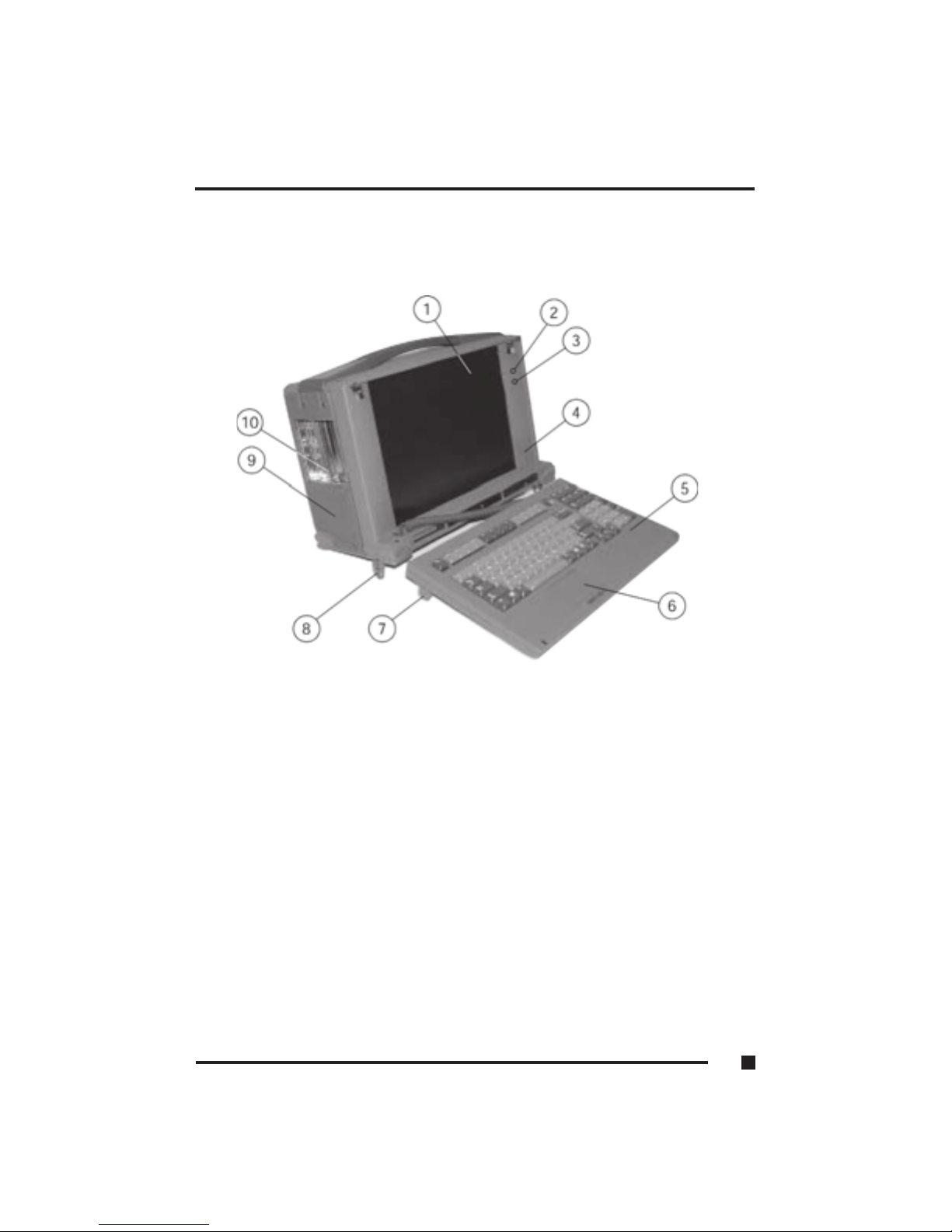
Figure 1.1 Features of the FlexPAC
1. Flat-Panel Display
2. Power LED
3. Hard Disk Drive LED
4. Stereo Speakers (2 each)
5. Keyboard
6. Embedded Touchpad
7. Keyboard Adjustment Feet (2 each)
8. System Tilt Feet (2 each)
9. Cover Grill
10. Expansion Slot Openings
1 ■Getting Started
1.3
Page 17
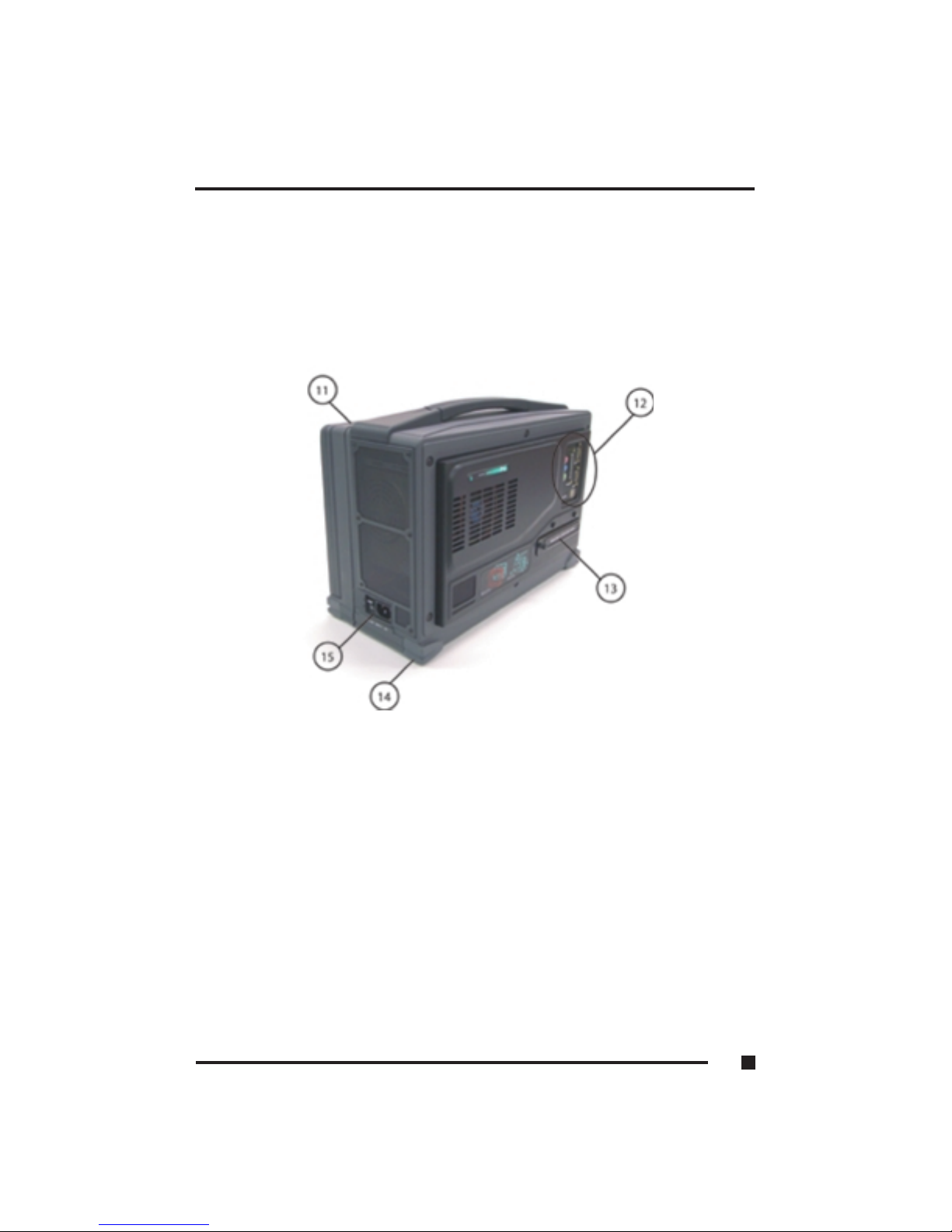
Figure 1.2 Features of the FlexPAC
11. Keyboard Release Button (2 each)
12. I/O Ports/Audio Jacks
13. Optional Removable Hard Disk Drive
14. Corner Bumpers (4 each)
15. Power Switch/Power Receptacle
1 ■Getting Started
1.4
Page 18

Figure 1.3 Features of the FlexPAC
16. Carrying Handle
17. Cover Grill
18. Optional PCMCIA CardBus Slots
19. CD-ROM or (Optional CD-RW, DVD or DVD-CD-RW)
20. Floppy Disk Drive
1 ■Getting Started
1.5
Page 19

Features of the FlexPAC
1. Flat-Panel Display - FlexPAC has a 14.1 inch XGA 1024 x 768 active
matrix, color display.
2. Power LED - The green colored LED illuminates when the FlexPAC is
powered “On.”
3. Hard Disk Drive LED - The red colored LED indicates hard disk drive
access.
4. Stereo Speakers - Two internal speakers located on the front panel,
provide stereo sound for the FlexPAC.
5. Keyboard - The 104/105-key keyboard, with an embedded touchpad,
closes up against the flat-panel display for easy storage and protects the
display during transportation.
6. Embedded Touchpad - An integrated touchpad eliminates the need for
a mouse device.
7. Keyboard Adjustment Feet - Use the two adjustment feet to modify
the angle of the keyboard.
8. System Tilt Feet - Two system tilt feet, located on the bottom of the
unit, sets the viewing angle of the FlexPAC.
9. Fan Filter Cover - Remove the fan filter cover to access the washable
air filter.
10. Expansion Slot Openings - The expansion slot openings provide access
to the I/O ports on the installed add-in cards. There are four available PCI
slots.
11. Keyboard Release Buttons - These two buttons release the keyboard
from the front of the unit.
12. I/O Ports/Audio Jacks - The FlexPAC provides a parallel port, 2 serial
ports, 2 USB ports and 3 audio jacks on the rear panel.
1 ■Getting Started
1.6
Page 20

13. Removable Hard Disk Drive - The FlexPAC can be equipped with an
optional removable hard disk drive.
14. Corner Bumpers - Four shock absorbing corner bumpers provide added
protection during transport of the portable FlexPAC.
15. Power Switch/Power Receptacle - The “On/Off” power switch and the
power cord receptacle are located on the side panel to the right of the
display.
16. Carrying Handle - A convenient carrying handle for easy transport and
handling is provided on the FlexPAC.
17. Cover Grill - Remove the fan filter cover to access the washable
air filter.
18. PCMCIA/CardBus Slot - The FlexPAC can be equipped with an
optional PCMCIA/CardBus slot that accepts either two type II or one
type III PC cards.
19. CD-ROM - The FlexPAC comes standard with a multi-speed super slim
CD-ROM or an optional CD-RW.
20. Floppy Disk Drive - A 1.44MB, 3.5 inch floppy disk drive is standard
on the FlexPAC.
1 ■Getting Started
1.7
Page 21

Removing the Keyboard
When transporting or not in use, the keyboard closes up neatly against the
flat-panel display. Not only is the screen protected, but the keyboard remains
with the main unit at all times. It can be easily released from the main unit
when ready for use.
1. Place the FlexPAC on a flat, sturdy surface with the carrying handle facing
up and the keyboard facing you.
2. Located on the top of the FlexPAC are two keyboard release buttons (see
Figure 1.5, Item 6). Press both buttons down simultaneously. This will
release the keyboard from the front of the unit.
3. Slightly lift up on the keyboard to remove the mounting tabs (see Figure
1.5, Item 10) out from the mounting slots (see Figure 1.4, Item 4). Place
the keyboard in front of the system. You can flip out the adjustment feet,
on the bottom of the keyboard, if you wish to modify the angle (see Figure
1.5, Item 9).
NOTE: The FlexPAC is shipped with the keyboard already connected,
however, the cable can be disconnected and re-connected when
needed. The keyboard cable connector is located on the lower
left side of the front panel, below the speaker (see Figure 1.4,
Item 2).
4. Closing Up the Keyboard - Before closing the keyboard up against the
flat-panel, insert the keyboard cable into the provided storage space
(channel) along the back of the keyboard (see Figure 1.6, Item 13). This
keeps the keyboard cable out of the way and protects it from becoming
pinched. Then, insert the mounting tabs (see Figure 1.5, Item 10) into their
mating slots (see Figure 1.4, Item 4) and close the keyboard up against the
flat-panel, making certain that the retaining hooks snap securely into place
(see Figure 1.5, Item 7).
1 ■Getting Started
1.8
Page 22
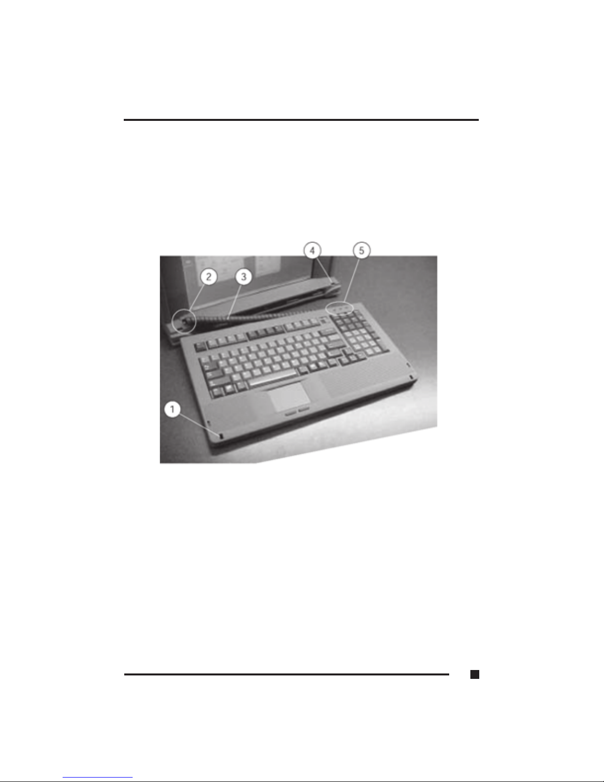
Figure 1.4 FlexPAC Keyboard
1. Keyboard Retaining Slot (2 each)
2. Keyboard Cable Connector
3. Keyboard Cable
4. Keyboard Mounting Slot (2 each)
5. Keyboard LED (Num Lock, Caps Lock & Scroll Lock)
1 ■Getting Started
1.9
Page 23
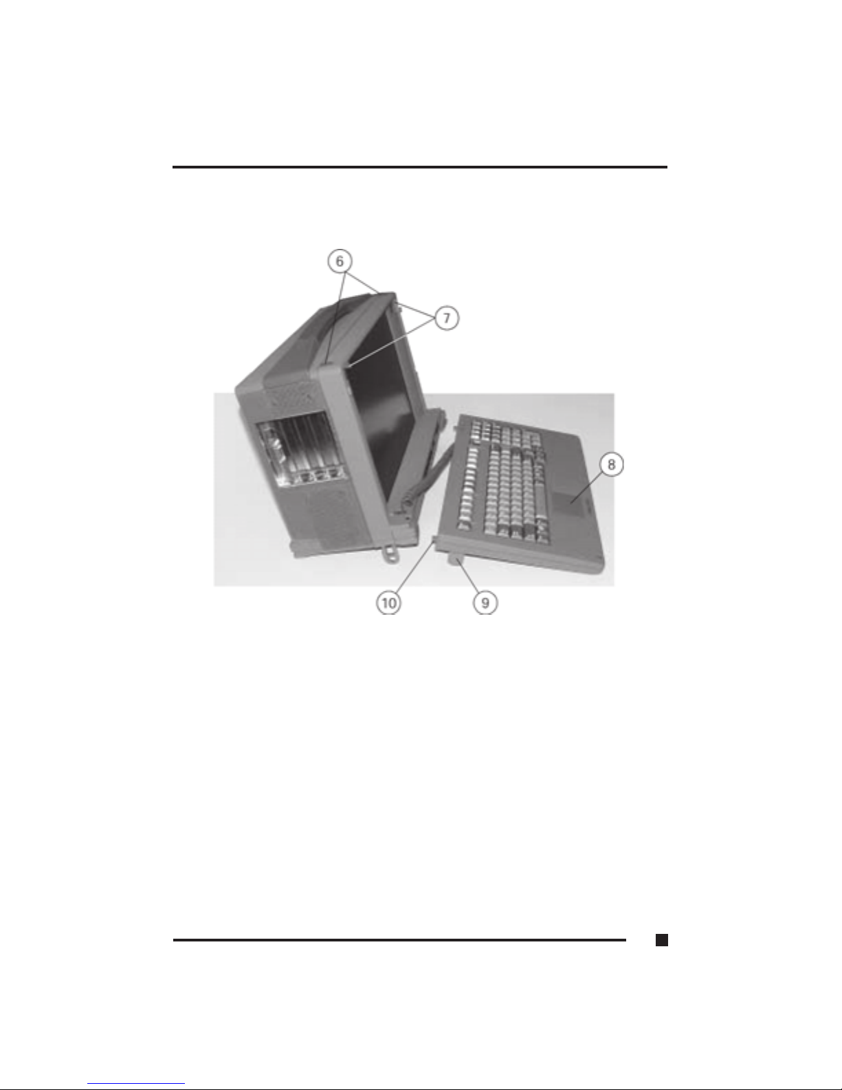
Figure 1.5 Keyboard Features
6. Keyboard Release Buttons (2 each)
7. Keyboard Retaining Hooks (2 each)
8. Embedded Touchpad
9. Keyboard Adjustment Feet (2 each)
10. Keyboard Mounting Tabs (2 each)
1 ■Getting Started
1.10
Page 24
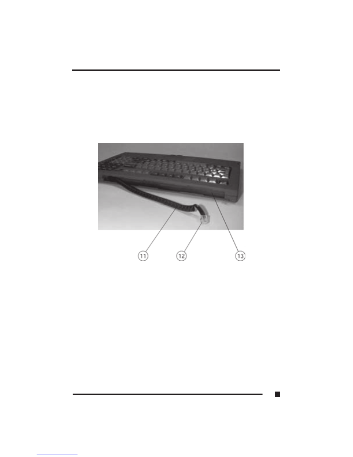
Figure 1.6 Keyboard Cable Stowage Channel
11. Keyboard Cable
12. Modular Keyboard Jack
13. Keyboard Cable Stowage Channel
1 ■Getting Started
1.11
Page 25
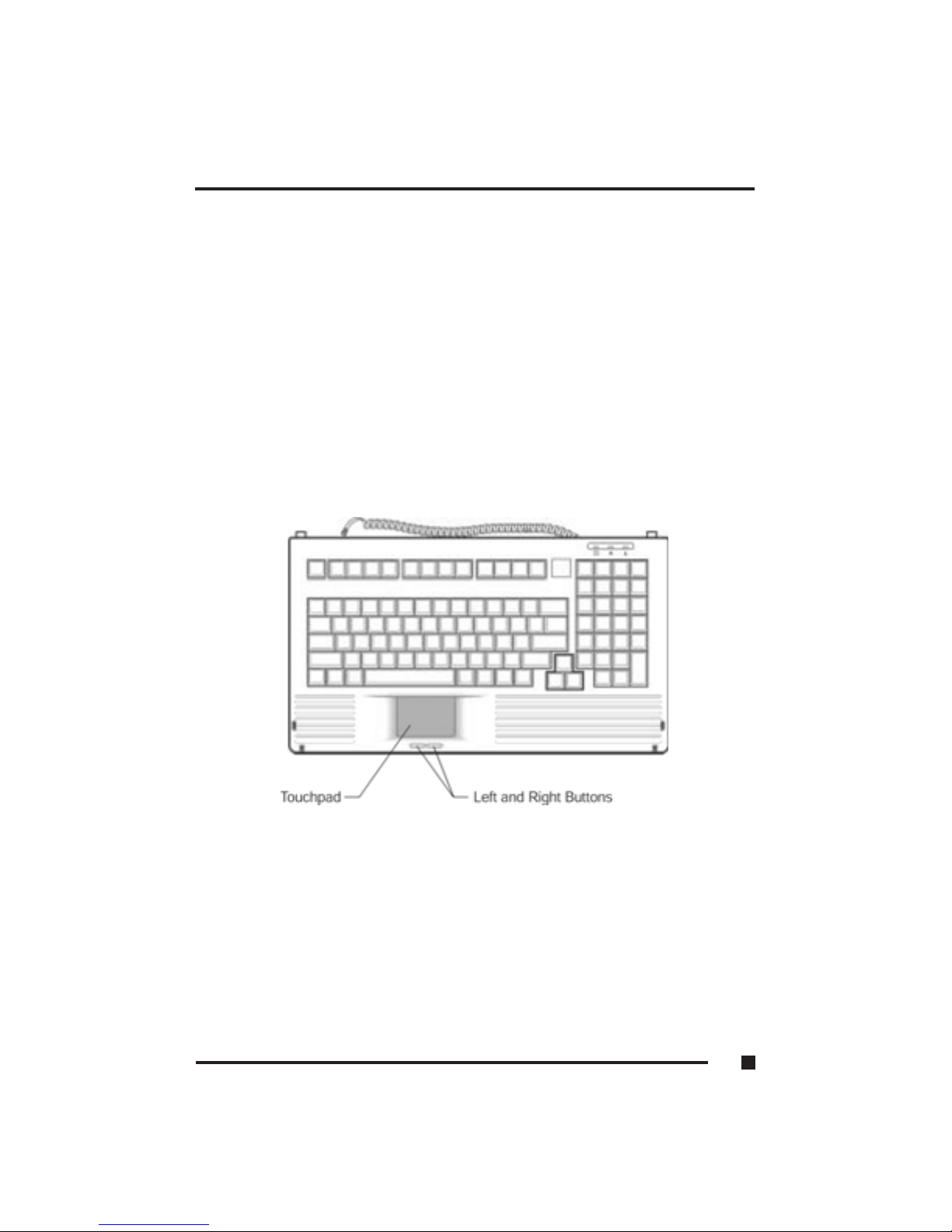
Keyboard
The FlexPAC comes with a full size, AT compatible, 104/105-key keyboard
with 12 function keys and dedicated cursor keys (see Figure 1.7). An
integrated touchpad is located below the keys with the left and right buttons
placed below it. The touchpad is pressure sensitive and works by the touch
and movement of your fingertip. Smoothly move your fingertip over the pad
in the direction in which you want to move the cursor. Refer to page 1.15 for
helpful tips on use of the touchpad.
The adjustment feet on the bottom of the keyboard enable you to adjust the
height and angle of the keyboard (see Figure 1.5, Item 9). The keyboard can
be tilted in conjunction with the system or it can be placed in a flat position in
front of the system.
Figure 1.7 FlexPAC Keyboard with Embedded Touchpad
1 ■Getting Started
1.12
Page 26

Keyboard Keys
Key Function
Enter Moves the cursor to the start of a new line. In most application
programs, it also executes a command.
Caps Lock When this key is engaged, the letter keys produce upper case
letters.
Shift When this key is pressed down along with another key, it
produces upper case letters (or the upper case character on
the keys). Also performs special functions when used in
combination with other keys.
Tab Moves the cursor horizontally to the next tab stop.
Esc Cancels or escapes from a command or a function.
F1 - F12 The keys on the top row of the keyboard labeled F1 through
F12 are called “function keys.” Special commands are defined
for each key. Refer to the user’s manual to determine the
function of each of these keys for a particular application
program. The BIOS also uses function keys to set some
configuration parameters.
Numeric These keys function as calculator keys when the “Num Lock”
light is on.
Keypad When the numeric keypad is active, the system disables the
alphabet keys doubling as numeric keypad keys.
Num Lock This key toggles the number pad between acting as numeric
keys or editing keys. When the keyboard “Num Lock” indicator
is lit, the number pad is active.
Prt Sc Sends the current information, showing on the display, to a
Sys Req connected printer. Pressing this key in conjunction with the
<Ctrl> key sends all output to a connected printer. Press this
key combination again to stop the function.
Back Space Deletes characters as it moves the cursor to the left. Use it to
correct typing mistakes.
Scroll Lock In some applications, information will move across the screen
differently when this key is engaged. It can change the text
scroll up and down feature.
1
■
Getting Started
1.13
Page 27

Pause Break Temporarily halts a running program. To continue using the
program again, press any key. Pressing the “Pause” key, in
conjunction with the <Ctrl> key, breaks the program.
Ctrl Works in combination with other keys to provide shortcuts or
to modify actions. Refer to the users manual for the application
program you are using. To use a <Ctrl > key combination, hold
down the <Ctrl> key and the other key simultaneously.
Alt The keyboard provides two “Alt” keys. The “Alt” key works in
conjunction with other keys to perform various commands or
functions. Refer to the users manual for the application
program you are using. To use an <Alt> key combination,
simultaneously hold down the <Alt > key along with the
other key.
Cursor Control Keys
Key Function
Home Moves the cursor to the first character position on the top line
of the screen.
End Moves the cursor to the last character position on the bottom of
the screen.
PgUp If this key is operable in the application program you are using,
it lets you scroll to the previous page.
PgDn If this key is operable in the application program you are using,
it lets you scroll to the next page.
Arrows The four direction arrow keys control the movement of the
cursor on the screen. They do not affect the displayed
character keys.
Delete Deletes the character to the right of the cursor. All remaining
characters to the right move one space to the left.
Insert Places the keyboard into the “insert mode.” While in the
“insert mode,” data entries are made at the current cursor
position and all data to the right of the cursor position moves
to the right. The keyboard stays in the insert mode until you
press the “Insert” key again.
1
■
Getting Started
1.14
Page 28

Keyboard Touchpad
The built-in touchpad is a convenient substitute for a mouse device. Its
function is similar to that of a two-button mouse. The left button is equivalent
to the left button on a mouse and the right button is equivalent to the right
button on a mouse (see Figure 1.7). Listed below are the key features of the
integrated touchpad embedded in the keyboard.
•To move the cursor: Place your fingertip on the surface of the touchpad
and slide it across, in the direction you wish the cursor to go.
•To click: Press the touchpad’s left or right button or lightly tap on the
touchpad.
•To double click: Either press the left button twice or lightly tap the
touchpad twice in quick succession.
•There are two ways to drag:
Move the cursor to the desired location, then press down the left button.
While still holding down the left button, move the cursor to the desired
location. Then, release the left button.
Move the cursor to the desired location. Quickly tap the touchpad as if you
were double clicking however, do not move your finger after the second
tap. While maintaining contact with the touchpad, move the pointer (drag
your finger) to the desired location. Lift your finger to complete the move.
1 ■Getting Started
1.15
Page 29

Figure 1.8 Rear Panel I/O Connections
1. Parallel Port
2. Serial Port (COM2)
3. Serial Port (COM1)
4. USB Ports (2 each)
1 ■Getting Started
1.16
Page 30

Figure 1.9 Side Panel Connections
5. 10/100 Ethernet Port
6. External Monitor Port
7. External Mouse Port
8. 10/100/1000 Ethernet Port
1 ■Getting Started
1.17
2GHz FlexPAC
3GHz FlexPAC
Page 31

I/O Connections
To expand your computing capabilities, the FlexPAC is equipped with several
interface ports and connection receptacles. These connectors support
a variety of external peripheral devices. A bi-directional parallel port, two
serial ports and two USB ports are located on the rear panel (see Figure 1.8).
In the expansion slot opening, on the side panel to the left of the display, is an
external monitor port and a 10/100 Base-T ethernet port (see Figure 1.9). The
power switch and the AC power cord receptacle are located side-by-side, on
the side panel, to the right of the display (see Figure 1.10).
Parallel Port
The FlexPAC provides a 25-pin, bi-directional parallel port for connecting
a parallel printer or another parallel peripheral device. The parallel port is
located on the rear panel of the FlexPAC (see Figure 1.8). Before using the
parallel port, refer to the documentation provided by the manufacturer of your
parallel device for information on the installation.
Serial Ports
The FlexPAC includes two 9-pin serial ports for connecting a serial printer, an
external serial mouse or other external serial devices. The serial ports are
located on the rear panel (see Figure 1.8). Upon shipment, both serial ports,
COM1 and COM2, are fixed for RS-232 use.
USB Ports
The FlexPAC provides two USB (Universal Serial Bus) ports for connecting
USB compliant devices. USB devices can be conveniently connected and
disconnected while the system is running. Please refer to the device-specific
documentation for information on connecting and using USB devices. The
USB ports are located on the rear panel below the serial ports (see Figure 1.8).
1 ■Getting Started
1.18
Page 32

Ethernet Connector
The FlexPAC 2GHz is equipped with a 10/100 Base-T ethernet network connector
and the FlexPAC 3GHz has an additional 10/100/1000 Base-T connector. The
RJ45 ethernet input jacks allows you to connect the FlexPAC into an existing
network. The ethernet ports are located in the expansion slot opening on the side
panel to the left of the display (see Figure 1.17).
External Monitor Port
The FlexPAC has an on board video controller, backed by 16MB of memory,
for driving the flat-panel display. The unit includes a 15-pin, high density,
sub-D VGA port for connecting an external monitor. I t is accessible on the
side panel, in the expansion slot opening (see Figure 1.9, Item 6). This analog
video monitor port supports either simultaneous (at the same resolution) or
independent display operation. It is not necessary to connect an external
monitor to the FlexPAC, but by using an external monitor you can achieve
higher resolutions than on the internal flat-panel display.
External Mouse
If preferred, a pointing device can be used in place of the embedded touchpad
on the standard keyboard included with the FlexPAC. Only a serial or USB
type mouse can be used along with the standard keyboard. If using a serial
mouse, use one of the 9-pin, RS-232 serial ports to connect it. If using a USB
mouse, use one of the USB ports to connect it. Please refer to the pointing
device-specific documentation for information on connecting and using the
external mouse. The serial and USB ports are located on the rear panel of the
FlexPAC (see Figure 1.8).
1 ■Getting Started
1.19
Page 33

Powering On the FlexPAC
Before you plug in the power cord or any other equipment for the FlexPAC,
take an inventory of each device and make sure you have all the appropriate
cables you need. If any cables are missing for the FlexPAC, immediately
contact Kontron technical support for a replacement.
The power switch and the power cord receptacle for the FlexPAC are located
side-by-side on the side panel to the left of the display (see Figure 1.10). The
FlexPAC requires an AC power source for operation.
1. Make sure the power switch is in the “Off” position. Also power “Off” any
other external peripheral devices connected to the FlexPAC.
2. Insert the female, 3-pin connector on the power cord into the power
receptacle on the side panel, next to the power switch.
3. Plug the other end of the power cord into a grounded 3-prong power outlet
or power strip.
4. Push the power switch in the “On” position.
5. Once you have turned the system “On,” it will begin a Power-On Self Test
(POST). If you want to review your hardware configuration while the
system is running the POST, press the <Del> key to enter the BIOS utility.
For more information on the BIOS utility, refer to Chapter 3.
Bypassing the Memory Test
When your start up the FlexPAC, the Basic Input/Output System (BIOS)
performs the Power-On Self Test (POST) to run a check on things such as the
hard drive, the floppy drive, and the system’s memory. If you have a lot of
memory installed in your system, this can be a slow process. To bypass the
memory test, press the <ESC> key when the following message is displayed:
Press <ESC> to Bypass Memory Test
1 ■ Getting Started
1.20
Page 34
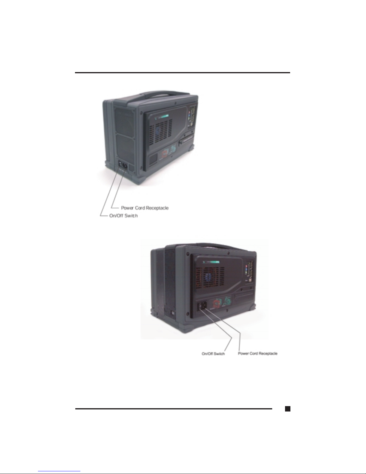
Figure 1.10 Power Switch/Power Cord Receptacle
1 ■Getting Started
1.21
4-Slot FlexPAC
6-Slot FlexPAC
Page 35

Adjusting the Display Viewing Angle
You can adjust the display angle of the FlexPAC for your viewing comfort.
The FlexPAC has tilt adjustment feet on the bottom of the unit. Flipping these
feet out will angle the display upwards.
Nylon Carrying Case
The FlexPAC is designed for travel and mobility. It can withstand the rigorous
handling of transport and setup, and can operate in demanding field
conditions and changing environments. The durable carrying case included
with your system allows you to bring along reports, software, cables and the
necessities needed to perform your job while out in the field. The padded
carrying case not only provides a side pouch in which to stow your items, it
also protects the outer casing. A removable, over-the-shoulder carrying strap
is also included with the unit.
1 ■Getting Started
1.22
Page 36
Audio Function
The FlexPAC is equipped with an audio function. The audio function includes
an integrated audio sound chip, two internal stereo speakers and three audio
hook-up jacks (line-in, line-out and microphone). The audio jacks are located
on the rear panel, next to the parallel port (see Figure 1.12). The internal
stereo speakers are located on each side of the flat-panel display (see Figure
1.1, Item 4).
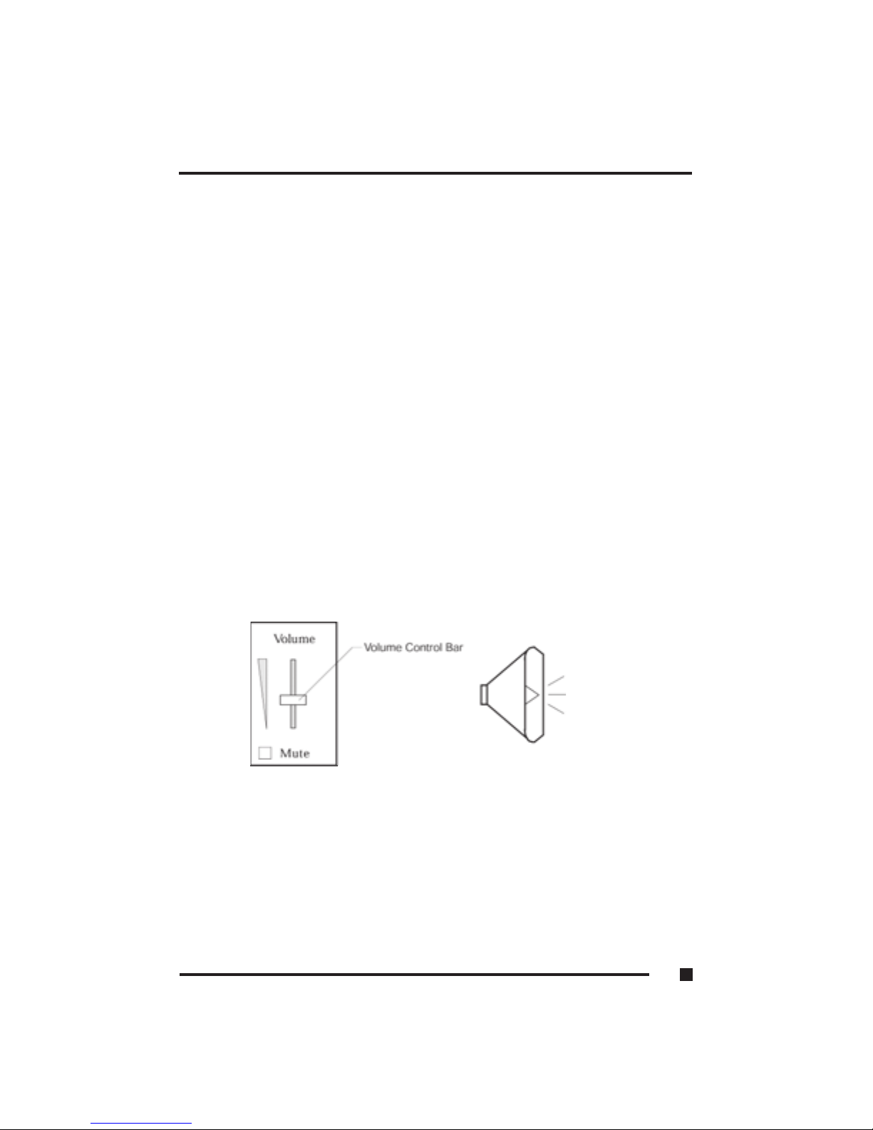
Volume Control Adjustments
Windows operating systems provide “On-Screen” volume control for making
the sound adjustments. If using a different operating system, refer to it’s user
manual for “Volume Control” support.
1. Click once on the “Sound” icon located along the “task-bar” in the lower
right-hand corner of the display.
2. An on-screen “Volume Control” box will appear in the lower right-hand
corner of the screen, just above the “Sound” icon (see Figure 1.11).
3. To raise or lower the volume: Click on the “Volume Control” bar, and
while holding down the mouse button, move the volume control bar
upwards or downwards. Push the volume control bar up to raise the sound.
Push the volume control bar down to lower the sound.
On-Screen Volume Control Sound Icon
Figure 1.11 On-Screen Volume Control (Windows OS only)
1 ■Getting Started
1.23
Page 37
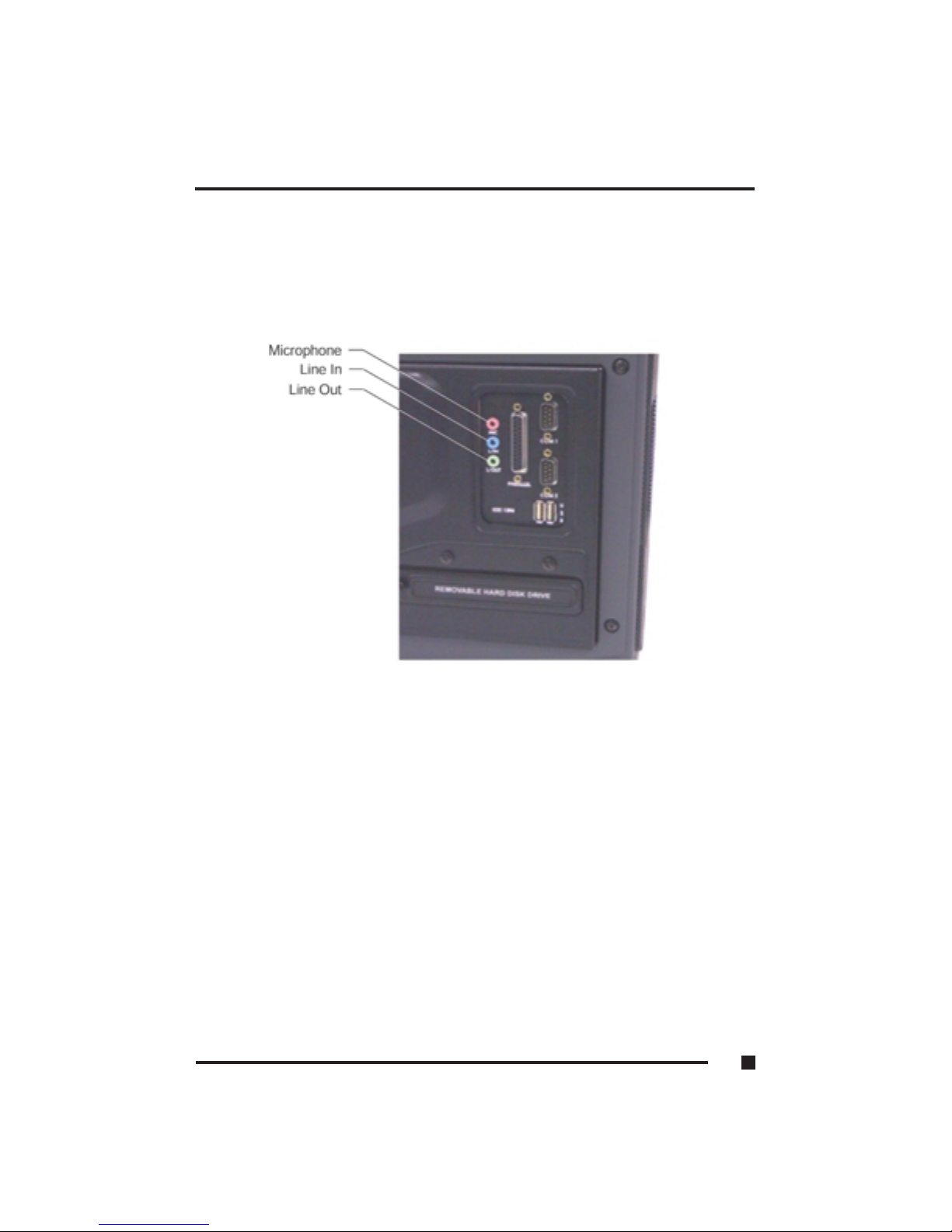
Figure 1.12 External Audio Jacks
1 ■Getting Started
1.24
Page 38

2
System
Description
Page 39

2 ■ System Description
SYSTEM DESCRIPTION
The FlexPAC is a high-performance system powered by a Pentium® 4
processor based on the advanced Intel 845 Chipset.
The highly compatible system is fully designed for maximum performance in
industrial environments. It can handle large software applications with ease
and still retain consistent configuration control.
Features
Specifications FlexPAC 2GHz FlexPAC 3GHz
Chipset Intel 845PE 400MHz or 533MHz
CPU 2.8GHz Pentium® 4
Bus Speed 533MHz
Memory 512MB DDR to 2GB DDR
Disk Storage 40GB EIDE Minimum Capacity Unformatted
Optional HDD Fixed or Removable 2nd HDD
Floppy Disk Drive 1.44MB
Multimedia Drives CD-ROM or Optional CD-RW, DVD or DVD-CD RW
Internal Display 14.1-inch XGA TFT, 16MB Video RAM
Video Memory M7 graphics controller, 16MB
Ext Display Supports Simultaneous External Display
640x480, 800x600, and 1024x768
I/O Ports 2 Serial Ports (16550 UART Compatible)
1 Enhanced Parallel Port (ECP/EPP Compliant)
Two USB 2.0 Ports
1) 10/100GHz BaseT Ethernet RJ45 Port
Keyboard AT Compatible, 104/105 Key w/ integrated Touch Style Mouse Pad
Audio Intel AC97, ICH2 Controller
Line-in, Line-out, and Microphone
PCMCIA/Card Bus
Options
Power Supply 300W, 100-240VAC, 50-60Hz
FlexPAC (4 Slots)
Expansion Slot Options 3 PCI & 1 Shared PCI/ISA
Dimensions (WxHxD) 15.78x10.18x6.72in (40.08x25.8x17.07cm)
Weight 18lbs (8.18kg)
FlexPAC (6 Slots)
Expansion Slot Options 5 PCI & 1 Shared PCI/ISA
Dimensions (WxHxD) 16.00x11.00x9.75in (40.6x27.9x4.7cm)
Weight 23lbs (10.55kg)
2 Type II or One Type III
2.1 ■
Page 40

Driver for USB 2.0
Please use Microsoft Windows Update to download the USB 2.0 driver.
Drivers Installation
The drivers for the FlexPAC are provided on the “Drivers/User Manual” CD
included with your system. This section provides driver installation
procedures for Windows 2000/XP and Windows NT 4.0 operating
systems. Some drivers contain “Readme.txt” files. These files include
updates, changes or information relating to the drivers you are about to
install. Read the “Readme.txt” files before loading drivers.
Intel Chipset Software Installation Utility
The Intel Chipset Software Utility enables “Plug and Play” INF support for
Intel chipset components. Use the following procedures to install the
drivers for Windows 2000/XP.
1. Power “On” the FlexPAC. Insert the CD that comes with the CPU card.
A screen appears. Click Intel Chipsets and then click Intel 845G Drivers.
2. Click Intel Chipset Software Installation Utility.
3. When the Welcome screen appears, click Next.
4. Click Yes to accept the software license agreement and proceed with
installation.
5. In the Readme Information screen, click Next to continue.
6. Setup is complete. Click Finish to restart the computer to allow changes to
take effect. When the computer restarts, the system will find devices.
Restart your computer when prompted.
2 ■ System Description
2.2
Page 41

Intel Application Accelerator
Use the following installation procedure to install the “Intel
Application Accelerator” driver using the Install Shield Wizard under
Windows 2000/XP and Windows NT 4.0.
1. Power “On” the FlexPAC. Insert the CD that comes with the CPU
card into the CD-ROM.
2. Click the Intel Application Accelerator. The Welcome screen of the
Install Shield Wizard for the accelerator appears. Click yes to accept
the software license agreement and proceed with installation.
3. Select the folder in which the Setup will install files. Click Next to accept
the default folder, or click Browse to choose a different location.
4. Select a Program folder. Click Next to accept the default program folder or
enter a folder name you prefer.
5. The Install Shield Wizard has completed the installation. Remove the CD.
Click Finish to restart the system for changes to take effect.
2 ■ System Description
2.3
Page 42

Windows NT 4.0 Drivers
The following drivers are for Windows NT 4.0 operating systems only.
Windows NT 4.0 must be loaded on your system before attempting the
installation of these drivers.
Installing Windows NT 4.0 VGA Drivers
Use the following procedure to install the “ATI Mobility Radeon M6”
graphics driver in the Windows NT 4.0 environment. It is recommended that
you make a backup copy of the “ATI Mobility Radeon M6” VGA drivers for
safekeeping.
1. Power “On” the FlexPAC. Insert the supplied “Drivers/User Manual” CD
into the CD-ROM.
2. An “Inside this CD” window will appear. Click on the VGA Card icon on
the left side of the window.
3. Then click on ATI Mobility Radeon VGA Driver on the right
side of the window.
4. When the “Welcome” window appears, click on Next to continue.
5. Click on Yes to accept the software license agreement and proceed with
the installation process.
6. In the “Select Components” window, click on the Express Recommended
installation method, then click on Yes to start the file copying process.
7. The Setup process is now complete. Remove the CD. Click on Finish to
restart the system for the changes to take effect.
2 ■System Description
2.4
Page 43

Installing Windows NT 4. 0 PCI Ethernet Drivers
Use the following procedure to install the PCI Ethernet drivers for Windows
NT 4.0. If you are not using Windows NT 4.0, not do not use this procedure.
1. Before you can install the PCI Ethernet drivers, you must first transfer the
Windows NT 4.0 drivers from the supplied “Drivers/User Manual” CD
onto a floppy diskette. This installation diskette will be used to load the
drivers.
2. Power “On” the FlexPAC. Insert the supplied “Drivers/User Manual” CD
into the CD-ROM and insert a formatted floppy diskette into the floppy
disk drive.
3. When the initial window comes up, click on LAN Card. Then click on
Intel Pro LAN Drivers.
4. In the “Create Install Disk” window, select the Windows NT 4.0 operating
system to begin the transfer. When the transfer is complete, remove both
the CD and the floppy diskette. Use the installation diskette you just
created to install the Ethernet/LAN drivers.
For Installation of Intel Pro/100 and also repeat process for installation
of Intel Pro/1000.
1. In the Windows NT 4.0 environment, click on the Start button.
2. Go to the Settings option and select Control Panel.
3. Double click on Network Adapters Add.
4. Select Have Disk... then insert the installation diskette you just created
into the floppy disk drive and click on Ok.
5. Click on Ok Close, then enter the IP address. Remove the floppy
diskette. Close all applications and restart the system for the changes to
take effect.
2 ■System Description
2.5
Page 44

SigmaTel AC97 Audio Drivers for Windows NT 4.0
Use the following installation procedure to install the “SigmaTel AC97
Audio Drivers” in the Windows NT 4.0 environment.
1. Power “On” the FlexPAC. Insert the supplied “Drivers/User Manual” CD
into the CD-ROM.
2. An “Inside this CD” window will appear. Click on the Intel Chipsets icon
on the left side of the window.
3. Click on the Intel 845 Chipset Family Drivers.
4. Now click on the SigmaTel AC97 Audio Driver.
5. When the “Welcome” window for the “SigmaTel AC97 Audio Drivers”
Setup program appears, click on Next to continue.
6. Click on Yes to accept the software license agreement and proceed with
the installation process.
7. On the next window, select Install and click on Next to install the
“SigmaTel AC97 Audio Drivers.”
8. The Setup process is now complete. Remove the CD. Click on Finish to
restart the system for the changes to take effect.
9. After the system has restarted, a window will appear showing some
installation information. When prompted, restart the system to complete
the audio driver installation.
2 ■System Description
2.6
Page 45

Windows 2000/XP Drivers
The following drivers are for Windows 2000/XP operating systems.
Windows 2000/XP must be loaded before attempting installation.
Installing Windows 2000/XP VGA Drivers
Use the following procedure to install the “ATI Mobility Radeon” graphics
driver in the Windows 2000/XP environment. It is recommended that you
make a backup copy of the “ATI Mobility Radeon” VGA drivers for
safekeeping.
1. Power “On” the FlexPAC. Insert the CD that comes with the CPU card.
On the initial screen, click the VGA Card icon on the left, which brings
up a new screen. Click ATI Mobility Radeon M7 Series VGA Driver.
2. When the Welcome screen appears, click Next.
3. Click Yes to accept the software license agreement and
proceed with the installation process.
4. Select the Express icon and click Next.
5. The Setup process is complete. Remove the CD. Click Finish to
restart the system for changes to take effect. Restart your computer
when prompted.
2 ■ System Description
2.7
Page 46

Installing Windows 2000/XP Intel Pro LAN 100 Drivers
Use the following procedure to install Intel PRO LAN 100 drivers for
Windows 2000/XP.
1. Power “On” the FlexPAC. Insert the CD that comes with the CPU card.
A new screen appears. Click the LAN Card icon on the left to make the
LAN drivers selection. Click Intel PRO LAN Drivers.
2. Click Install Now.
3. Click Restart Now to enable new settings to take effect.
2 ■ System Description
2.8
Page 47

SigmaTel AC97 Audio Drivers for Windows 2000/XP
Use the following installation procedure to install the “SigmaTel AC97 Audio
Drivers” in the Windows 2000/XP environments.
1. Power “On” the FlexPAC. Insert the CD that comes with the CPU card. A
new screen appears. Click Intel Chipsets, then Intel 845G Chipset
Drivers.
2. Click the SigmaTel AC97 Audio Driver.
3. When the “Welcome” window for the “SigmaTel AC97 Audio Drivers”
Setup program appears, click Next.
4. Click Finish to restart the computer and to allow changes to take effect.
2 ■ System Description
2.9
Page 48

3
Configuration
Page 49

CONFIGURATION
The BIOS Setup
This chapter discusses the “Award Software Setup” utility program built into
the BIOS ROM. The “Setup” utility program allows users to modify the basic
system configurations and settings. The information is then stored in batterybacked RAM so that it retains the “Setup” information when the power is
turned “Off.”
The Award BIOS installed in your computer system’s ROM is a custom
version of an industry standard BIOS. This means that it supports Intel
Pentium® processors in a standard IBM-AT® compatible input/output
system. The BIOS provides critical low-level support for standard devices
such as disk drives and serial and parallel ports.
The Award BIOS has been customized by adding important, but non-standard,
features such as virus and password protection, as well as special support for
the detailed fine-tuning of the chipset controlling the entire system.
This chapter is intended to guide you through the process of configuring your
system using the “Setup” utility.
Starting Setup
The Award BIOS provides a “Setup” utility for specifying the system
configurations and settings. The Award BIOS is immediately activated when
you first power on the computer. The BIOS reads the system information
contained in CMOS and begins the process of checking out the system and
configuring it. When the BIOS has finished it’s checking routine, it will seek
an operating system on one of the disks, then launch it and turn control over to
that operating system. If you don’t enter the “Setup” utility immediately after
start-up, the POST (Power-On Self Test) will continue with it’s test routines,
preventing you from entering the “Setup” utility.
3 ■Configuration
3.1
Page 50

Entering Setup
While the BIOS is in control, the “Setup” utility can be activated in one of
two ways:
1. By pressing the <Del> key immediately after switching the system “On.”
2. By pressing the <Del> key when the following message appears briefly at
the bottom of the screen during the POST.
If the message disappears before you respond and you still wish to enter
“Setup,” you can restart the system by simultaneously pressing the <Ctrl>
<Alt> and <Del> keys. If you do not press the keys at the correct time and the
system does not boot, an error message will be displayed and you will again
be asked to do the following:
1. Press the <F1> key to continue
2. Press the <Del> key to enter Setup
Using Setup
Use the arrow keys to highlight one of the displayed options, press <Enter> to
select it, use the Page Up <PgUp> and Page Down <PgDn> keys to scroll
through the entries, press <F1> for help and press <Esc> to quit. The
following table provides additional details about how to navigate in the
“Setup” utility by use of the keyboard.
Up Arrow Scroll up to the previous item
Down Arrow Scroll down to the next item
Left Arrow Move to the item on the left
Right Arrow Move to the item on the right
Esc Key Main Menu: Quit and not save changes to CMOS
Status Page Setup & Option Page Setup menu’s: Exit
current page and return to “Main” menu
3 ■Configuration
3.2
Page 51

PgUp Key Scroll upwards to highlight an option
PgDn Key Scroll downwards to highlight an option
+Key Increase the numeric value of
-Key Decrease the numeric value of
F1 Key General help
(Status Page Setup & Option Page Setup menu’s only)
(Shift) F2 Key Change the color from a total of 16 colors. <F2> to select
color forwards, Shift <F2> to select color backwards.
F3 Key Calendar (Status Page Setup menu only)
F4 Key Reserved
F5 Key Restore previous CMOS values
(Option Page Setup menu only)
F6 Key Load the default CMOS value from BIOS default table.
(Option Page Setup menu only)
F7 Key Load the default
F8 Key Reserved
F9 Key Reserved
F10 Key Save all the CMOS changes (Main menu only)
Getting Help
Press the <F1> key to display a small “Help” screen that describes the
appropriate keys to use and the possible selections for the highlighted option.
To exit the “Help” screen, press the <Esc> key or the <F1> key.
In Case of Problems
If, after making and saving system changes in “Setup,” you discover that your
computer is no longer able to boot, the Award BIOS supports an override to
the CMOS settings. This override resets your system to it’s default settings.
Only alter the settings which you thoroughly understand. It is strongly
recommended that you avoid making any changes to the default settings.
These default settings have been carefully chosen to provide the absolute
maximum performance and reliability. Even a seemingly small change to the
“Chipset Setup” has the potential for causing you to use the override.
3 ■Configuration
3.3
Page 52

Main Menu
When you enter the Award BIOS CMOS Setup utility, the “Main” menu will
appear on the screen. Use the following “Main” menu to select from several
“Setup” categories and two exit choices. Use the arrow keys to select among
the categories and press <Enter> to accept and enter the sub-menus.
ROM PCI/ISA BIOS
CMOS SETUP UTILITY
AWARD SOFTWARE, INC.
STANDARD CMOS SETUP FREQUENCY/VOLTAGE CONTROL
ADVANCED BIOS FEATURES LOAD FAIL-SAVE DEFAULTS
ADVANCED CHIPSET FEATURES LOAD OPTIMIZED DEFAULTS
INTEGRATED PERIPHERALS SET SUPERVISOR PASSWORD
POWER MANAGEMENT SETUP SET USER PASSWORD
PnP/PCI CONFIGURATIONS SAVE & EXIT SETUP
PC HEALTH STATUS EXIT WITHOUT SAVING
ESC : Quit : Select Item
F10 : Save & Exit Setup (Shift)F2 : Change Color
Time, Date, Hard Disk Type
NOTE: The section directly below the “Setup” categories, on the “Main”
menu, displays the control keys for the menu. The other section, at
the bottom of the screen, displays a brief description of the current
highlighted selection on the menu.
3 ■Configuration
3.4
Page 53

■
Standard CMOS Setup - This “Setup” screen contains the basic hardware configurations
needed to set up a working system.
■
Advanced BIOS Features - This “Setup” screen contains options to improve your
system and set up the special enhanced features.
■
Advanced Chipset Features - This “Setup” screen sets all the featured functions of
the chipset.
■
Integrated Peripherals - This “Setup” screen sets all the options of the IDE hard drive
and programmed input/output features.
■
Power Management Setup - This “Setup” screen configures the power saving functions.
■
PnP/PCI Configurations - This “Setup” screen configures the settings for the PnP/PCI
bus system.
■
PC Health Status - This “Setup” screen configures the parameters which determines
the health status of the PC.
■
Frequency/Voltage Control - This “Setup” screen configures the processor settings.
■
Load Fail-Safe Defaults - The BIOS defaults have been set by the manufacturer and
represent settings which provide minimum requirements for the system to operate.
■
Load Optimized Defaults - The chipset defaults are settings which provide for
maximum system performance.
■
Set Supervisor Password - This option is used to set the password which protects
the system and the “Setup” utility.
■
Set User Password - This option sets the password that will be used exclusively
for the system only.
■
Save & Exit Setup - Saves CMOS value changes to CMOS and exits “Setup.”
■
Exit Without Saving - Abandons all the CMOS changes and exits “Setup.”
3
■
Configuration
3.5
Page 54

Standard CMOS Setup
The “Standard CMOS Setup” menu allows you to record the basic hardware
configurations in your computer system, set the system clock and set any error
handling options. Since the system board is already installed in a working
system, there should be no need to select this category. You should only select
this category if you want to change your system hardware configurations, the
on board battery fails or if the settings stored in the CMOS memory gets lost
or damaged.
STANDARD CMOS SETUP
AWARD SOFTWARE, INC.
Date (mm:dd:yy) : Tue Mar 26 2001
Item Help
Time (hh:mm:ss) : 00 : 00 : 00
Menu Help
IDE Primary Master : Auto Detect Change the day, month
IDE Primary Slave : Auto Detect year and century
IDE Secondary Master : Auto Detect
IDE Secondary Slave : Auto Detect
Drive A : 1.44M, 3.5 in.
Drive B : None
Video : EGA/VGA
Halt On : All Errors
Base Memory : 640K
Extended Memory : Auto Detect
Total Memory : Auto Detect
The “control keys” for this menu are listed at the bottom of the menu. If you
need help in any option field, you can press the <F1> key. It will display
relevant information to help you with the selected option. The memory
display in the lower right-hand side of the menu is read-only. It will adjust
automatically according to when the memory changes. Each item on this
menu will be explained on the following pages.
3 ■Configuration
3.6
Page 55

Date
The date format is <day>, <month> <date> <year>. To set the date, highlight
the “Date” option and use the PageUp/PageDown or the +/- keys to set the
current date.
Day: Sun to Sat
Month: 1 to 12
Date: 1 to 31
Year : 1994 to 2079
Time
The time format is <hour> <minute> <second>. The time is based on the
24-hour military-time clock. For example: 1 p.m. is 13:00:00. To set the time,
highlight the “Time” option and use the PageUp/PageDown keys or the
+/- keys to set the current time.
Hour: 00 to 23
Minute: 00 to 59
Second: 00 to 59
3 ■Configuration
3.7
Page 56

Primary/Secondary Master and Slave
The on board PCI IDE connectors provide Primary and Secondary channels
for connecting up to four IDE hard disk drives or other IDE devices. Each
channel can support up to two hard disk drives; the first is the “Master” and
the second is the “Slave.”
Press <Enter> to configure the hard disk drive. The options include Auto,
Manual and None. Select “Manual” to manually define the drive information.
You will be asked to enter the following items.
CYLS: Number of cylinders
HEAD: Number of read/write heads
PRECOMP: Write pre-compensation
LANDZ: Landing zone
SECTOR: Number of sectors per track
MODE: Auto
Normal HDD < 528MB
Large For MS-DOS only
LBA HDD > 528MB
(and supports Logical Block Addressing)
Drive A/Drive B
Drive A and Drive B are categories that identify the type(s) of floppy disk
drive(s) installed in the FlexPAC.
3 ■Configuration
3.8
Page 57

Video
The video category selects the type of video display card installed in your
system.
EGA/VGA Enhanced Graphics Adapter/Video Graphics Array, for EGA,
VGA, SEGA, SVGA or PGA monitor adapters
Halt On
This category determines whether the computer will halt if an error is detected
during power up.
All Errors Whenever the BIOS detects a non-fatal error, the
system will stop and you will be prompted.
No Errors The system boot will not be halted for any errors that
may be detected.
All, The system boot will not be halted for a keyboard error;
But Keyboard it will stop for all other errors.
All, The system boot will not be halted for a disk error; it
But Diskette will stop for all other errors.
All, The system boot will not be halted for a keyboard or
But Disk/Key disk error; it will stop for all other errors.
3 ■Configuration
3.9
Page 58

Advanced BIOS Features Setup
The “Advanced BIOS Features Setup” menu allows you to configure and
improve your system for basic operation. It allows you to set up some special
features according to your preference. You have the opportunity to select the
system’s default speed, boot-up sequence, keyboard operation, shadowing and
security features.
ROM PCI/ISA BIOS
ADVANCED BIOS FEATURES SETUP
AWARD SOFTWARE, INC.
Virus Warning : Disabled ITEM HELP
CPU IL1 and L2 Cache : Enabled
Hyper-Threading Technology : Enabled **
Quick Power-On Self Test : Enabled Menu Level
First Boot Device : Floppy
Second Boot Device : HDD-0 Allows you to choose the
Third Boot Device : CD-ROM VIRUS warning feature for
Boot Other Device : Enabled the IDE Hard Disk Boot
Swap Floppy Drive : Disabled sector protection. If this
Boot Up Floppy Seek : Enabled function is enabled and
Boot Up NumLock Status : On someone attemps to write
Gate A20 Option : Fast data into this area, BIOS
Typematic Rate Setting : Disabled will show a warning
Typematic Rate (char/sec) : 6 message on screen and
Typematic Delay (Msec) : 250 alarm beep.
Security Option : Setup
APIC Mode : Enabled
MPS Version Control for OS : 1.4
OS Select for DRAM > 64MB : Non-OS2
Report No FDD for WIN 95 : No
Small Logo (EPA) Show : Enabled
** For 3GHz FlexPAC Only
3 ■Configuration
3.10
Page 59

Virus Warning
This option protects the boot sector and partition table of your hard disk
against accidental modifications. If an attempt is made, the BIOS will halt the
system and display a warning message (such as the one below.) If this occurs,
you can either allow the operation to continue or run an anti-virus program to
locate and remove the problem.
! WARNING !
Disk boot sector is to be modified
Type “Y” to accept write or “N” to abort write
Award Software, Inc.
Enabled Activates automatically when the system boots. When the system
boots, it causes a warning message to appear when anything
attempts to access the boot sector or hard disk partition table.
Disabled No warning message will appear when anything attempts to access
the boot sector or hard disk partition table.
NOTE: Many disk diagnostic programs, which attempt to access the
boot sector table, can cause the above virus warning. If you are
running this type of program, it is recommended that you disable
the “Virus Warning” feature beforehand.
3 ■Configuration
3.11
Page 60

CPU L1 and L2 Cache
Cache memory is additional memory that is much faster than conventional
DRAM (system memory). CPU’s from the 486-type on up contain internal
cache memory and most modern PC’s have additional (external) cache
memory. When the CPU requests data, the system transfers the requested data
from the main DRAM into cache memory, for even faster access by the CPU.
These two options allow you to either enable (speed up memory access) or
disable the cache function.
Quick Power-On Self Test (POST)
This option speeds up the POST after you power up the system. If it is set to
enabled (Default), the BIOS will shorten or skip some of the check items
during POST.
Hyper-Threading Technology
This option activates hyper-threading technology feature.
First/Second/Third Boot Device
When enabled, this option determines which drive to search for first for the
operating system such as DOS.
Floppy LS-120/Zip HDD-0
SCSI CD-ROM HDD-1
HDD-2 HDD-3 LAN
Boot Other Device
This option allows the system to search for an operating system from devices
other than the ones selected in the “First/Second/Third Boot Device” option.
Swap Floppy Drive
This option allows you to determine whether or not to enable Swap Floppy
Drive. When enabled, the BIOS swaps the floppy drive assignments so that
Drive A becomes Drive B, and Drive B becomes Drive A.
3 ■Configuration
3.12
Page 61

Boot Up Floppy Seek
This option determines whether the BIOS checks for a floppy drive while
booting up. If it does not detect one (either due to improper configuration or
its absence), it will flash an error message.
Boot Up NumLock Status
This option allows you to activate the NumLock function after you power up
the system.
Gate A20 Option
This option determines how gate A20 is handled. Gate A20 is a device used
to address memory above 1MB. Initially, Gate A20 was handled through a
pin on the keyboard. Today, while keyboards still provide this support, it is
more common and much faster, for the system chipset to provide support for
Gate A20.
Typematic Rate Setting
When this option is disabled, holding down a key on your keyboard will
generate only one key stroke at a time. When enabled, you can set the next
two listed typematic control options.
Typematic Rate (Characters Per Second)
When this option is enabled, the system registers repeated keystroke speeds.
You can select the speed range from 6 to 30 characters per second.
Typematic Delay (Msec)
When the “Typematic Rate” option has been enabled, this option will allow
you to set the time interval for displaying the first and second characters.
3 ■Configuration
3.13
Page 62

Security Option
This option allows you to limit access to the “System” and to “Setup” utility.
When you select the “System” option, the system prompts for the “User
Password” every time you boot up. When you select the “Setup” option, the
system boots up and prompts for the “Supervisor Password” only when the
“Setup” utility is called up.
APIC Mode
This option determines the APIC (Advanced Programmable Interrupt
Controller) mode.
MPS Version Control for OS
This option specifies the MPS (Multi-Processor Specification) version for
your operating system. MPS version 1.4 added extended configuration tables
to improve support for multiple PCI bus configurations and improve future
expansion.
OS Select for DRAM > 64MB
This option allows the system to access greater than 64MB of DRAM
memory when running an OS/2 program. OS/2 depends on certain BIOS calls
to access memory.
Report No FDD for Win 95
If you are using Windows 95/98 without a floppy disk drive, select enabled to
release IRQ6. Its required to pass the Windows 95/98 SCT test. You should
also disable the FDC Controller option in the “Integrated Peripherals” Setup
category, when there is no floppy drive in the system. When disabled, the
BIOS will not report the missing floppy drive to Windows 95/98.
Small Logo (EPA) Show
The EPA logo appears on the right side of the monitor screen when the system
is booted up.
3 ■Configuration
3.14
Page 63

Advanced Chipset Features Setup
The following section describes how to configure your system based on
specific features of the installed chipset. The chipset manages bus speeds and
access to the system memory resources, such as Dynamic Random Access
Memory (DRAM) and external cache. It is strongly recommended that you
avoid making any changes to the chipset default settings. These default
settings have been carefully chosen to provide the absolute maximum
performance and reliability. The only time you might consider making any
changes is if data is being lost while using your system.
ROM PCI/ISA BIOS
ADVANCED CHIPSET FEATURES SETUP
AWARD SOFTWARE, INC.
2GHz FlexPAC 3GHz FlexPAC
DRAM Timing S electable : By SPD : By SPD
ITEM HELP
CAS Latency Time : 3 : 2.7
Menu Level
Active to Precharge Delay : 6 : 7
SDRAM RAS # to CAS # Delay : 3 : 3
SDRAM RAS # Precharge : 3 : 3
DRAM Data Integrity Mode : Non-E CC
Memory Frequency For : Auto : Auto
System BIOS Cacheable : Enabled : Enabled
Video BIOS Cacheable : Enabled : Enabled
Memory Hole at 15MB-16MB : Disabled
Delayed Transaction : Enabled : Enabled
Power Supply Type : ATX
Delay Prior to Thermal : 16 Min : 16 Min
ICH2 ISA Enable : Enabled : Enabled
AGP Graphics Aperture Size : 64MB : 64MB
DRAM Timing Selectable
This option refers to the method by which the DRAM timing is selected.
3 ■Configuration
3.15
Page 64

CAS Latency Timer
This option selects the CAS latency time in HCLKs of 2/2 or 3/3. The system
board designer has set the values for this option, depending on the DRAM
installed. Do not change the values of this option unless you change the
specifications of the installed DRAM or the installed CPU.
Active to Precharge Delay
This option selects the setting for the Active Precharge Delay.
DRAM RAS# to CAS# Delay
This option allows you to insert a delay between the RAS (Row Address
Strobe) and the CAS (Column Address Strobe) signals. This delay occurs
when the SDRAM is written to, read from or refreshed. Reducing the delay
improves the performance of the SDRAM.
DRAM RAS# Precharge
This option sets the number of cycles required for the RAS (Row Address
Strobe) to accumulate it’s charge before the DRAM refreshes.
DRAM Data Integrity Mode
This BIOS setting is used to configure the RAM’s data integrity mode. ECC
(Error Checking and Correction) should only be used if you are using 72-bit
ECC RAM. This will enable the system to detect and correct single-bit errors.
It will also detect double-bit errors, though it will not correct them. This
option provides increased data integrity and system stability at the expense of
a little speed.
Memory Frequency for 2GHz FlexPAC
This option sets the frequency of the installed DRAM memory. The settings
are Auto, PC100 and PC133.
Memory Frequency for 3GHz FlexPAC
This option sets the frequency of the installed DDR memory. The settings
are Auto, DDR 266 and DDR333.
3 ■Configuration
3.16
Page 65

System BIOS Cacheable
When enabled, this option activates caching of the system BIOS ROM at
F0000h-FFFFFh, resulting in better system performance. However, if any
program writes to this memory area, a system error may result.
Video BIOS Cacheable
When enabled, this option activates caching of the video BIOS ROM at
C0000h to F7FFFh, resulting in better video performance. However, if any
program writes to this memory area, a system error may result.
Memory Hole at 15MB - 16MB (for 2GHz FlexPAC Only)
In order to improve performance, certain space in memory can be reserved for
ISA cards. This option allows you to reserve 15MB to 16MB memory address
space to ISA add-in cards. This makes memory from 15MB and up
unavailable to the system. Add-in cards can only access memory up to 16MB.
Delayed Transaction
The chipset has an embedded 32-bit posted write buffer to support delayed
transaction cycles. Select enabled to support compliance with PCI
specification, version 2.1.
Power Supply Type (for 2GHz FlexPAC Only)
This field sets the power supply type that is in your system. By default, the setting
is set to ATX.
AGP Aperture Size (MB)
The option sets the aperture size of the graphics memory address space. The
aperture is a portion of the PCI memory address range dedicated for the
graphics memory address space. Host cycles that hit the aperture range are
forwarded to the AGP without any translation. The available settings are 4M,
8M, 16M, 32M, 64M, 128M and 256M.
Delay Prior to Thermal
This option activates the CPU thermal function after the system boots for the
set number of minutes.
ICH2 ISA Enable
This option activates the ICH2 function.
3 ■Configuration
3.17
Page 66

Integrated Peripherals
This “Setup” screen allows you to determine your hard disk configuration and
other integrated peripherals.
ROM PCI/ISA BIOS
INTEGRATED PERIPHERALS
AWARD SOFTWARE, INC.
On-Chip Primary PCI IDE : Enabled
HELP ITEM
On-Chip Secondary PCI IDE : Enabled
Menu Level
IDE Primary Master PIO : Auto
IDE Primary Slave PIO : Auto
IDE Secondary Master PIO : Auto
IDE Secondary Slave PIO : Auto
IDE Primary Master UDMA : Auto
IDE Primary Slave UDMA : Auto
IDE Secondary Master UDMA : Auto
IDE Secondary S lave UDMA : Auto
USB Controller 1.1 : Enabled
USB Controller 2.0 : Enabled **
USB Keyboard Support : Disabled
AC97 Audio : Auto
Init Display First : AGP
ICH4 LAN : Enabled **
IDE HDD Block Mode : Enabled
On Board FDC Controller : Enabled
On Board Serial Port 1 : 3F8/IR Q4
On Board Serial Port 2 : 2F8/IR Q3
UART Mode Select : Normal
UR 2 Duplex Mode : Half
On Board Parallel Port : 378/IR Q7
Parallel Port Mode : S PP
ECP Mode Use DMA : 3
PWR -On After PWR -Fail : Off
Midi Port Address : 330 *
Midi Port IRQ : 10 *
* For 2GHz FlexPAC Only
** For 3GHz FlexPAC Only
3 ■Configuration
3.18
Page 67

On Chip Primary/Secondary PCI IDE
The integrated peripheral controller contains an IDE interface with support
for two IDE channels. Select enabled to activate each channel separately.
IDE Primary & Secondary Master/Slave PIO
The IDE hard drive controllers can support up to two separate hard drives.
These drives have a master/slave relationship which is determined by the
cabling configuration used to attach them to the controller. Since the system
supports two IDE controllers, the primary and the secondary, you have the
ability to install up to four separate hard disk drives.
These options allow your system to work faster. Rather than have the BIOS
issue a series of commands to effect a transfer to or from the disk drive,
Programmed Input/Output (PIO) allows the BIOS to communicate with the
controller and the CPU directly. This method is simple, fast and more
efficient.
Your system supports five modes, numbered from 0 to 4, which primarily
differ in timing. When “Auto” is selected, the BIOS will use the best available
mode.
IDE Primary & Secondary Master/Slave UDMA
This option allows your system to improve disk I/O throughput to 33MB/sec
with the Ultra DMA feature.
USB Controller 1.1
This option activates the USB 1.1 controller.
USB Controller 2.0
This option activates the USB 2.0 controller. ( Only on the 3GHz FlexPAC)
USB Keyboard Support
Select “Enabled” if your system contains an Universal Serial Bus (USB)
controller and you are using an USB keyboard.
AC97 Audio
This option activates the AC97 (I CH2) audio function.
3 ■Configuration
3.19
Page 68

Initial Display First
This option allows the system to first initialize the AGP card on chip or the
display on the PCI slot.
NOTE: If the “On Board” option is selected, both the internal and external
display will be lost.
IDE HDD Block Mode
This option allows the hard disk controller to use the fast block mode to
transfer data to and from your hard disk drive.
Power On Function
This option determines the way you power “On” the system from the system
“Off” state.
On Board FDC Controller
Select “Enabled” if your system has a floppy disk controller (FDC) installed
on the system board and you wish to use it. If you install an add-in FDC or if
your system does not have a floppy disk drive, select “Disabled.” This option
allows you to select the on board FDD port.
On Board Serial/Parallel Port
These options allow you to select the on board serial and parallel ports and
their addresses.
Serial Port 1: 3F8/IRQ4
Serial Port 2: 2F8/IRQ3
Parallel Port: 378h/IRQ7
3 ■Configuration
3.20
Page 69

UART Mode Select
This option determines the UART2 mode in your computer. The settings are
normal, IrDA and ASKIR.
UR2 Duplex Mode
This option allows you to select between the Half Duplex or the Full Duplex
mode.
Parallel Port Mode
This option allows you to determine the parallel port mode function.
SPP: Standard Printer Port
EPP: Enhanced Parallel Port
ECP: Extended Capabilities Port
Power-On After Power Fail
This option sets the system power status, whether on or off, when the power
returns from a power failure situation.
3 ■Configuration
3.21
Page 70

Power Management Setup
The “Power Management Setup” allows you to save energy while effectively
using your system. It will shut down the hard disk and turn “Off” the video
display after a period of inactivity.
ROM PCI/ISA BIOS
POWER MANAGEMENT SETUP
AWARD SOFTWARE, INC.
Power-Supply Type : ATX **
ITEM HELP
ACPI Function : Enabled
ACPI Suspend Type : S1 (POS) *
Menu Level
Power Management : User Define
Video Off Method : V/H Sync+Blank
Video Off In Suspend : Yes
Suspend Type : Stop Grant
Modem Use IRQ : N/A
Suspend Mode : Disabled
HDD Power Down : Disabled
Soft-Off By PWR-BTTN : Instant-Off
CPU THRM-Throttling : 75% **
Wake Up By PCI Card : Disabled
Power-On By Ring : Disabled
Resume By Alarm : Disabled
Date (of Month) Alarm : 0
Time (hh:mm:ss) : 0
~ Reload Global Timer Events ~
Primary IDE 1 : Enabled
Primary IDE 0 : Enabled
Secondary IDE 0 : Enabled
Secondary IDE 1 : Enabled
FDD, COM, LPT Port : Enabled
PCI, PIRQ [A-D] # : Enabled
* For 2GHz FlexPAC Only
** For 3GHz FlexPAC Only
ACPI Function
This option activates the ACPI (Advance Configuration and Power Interface)
support on the system card.
3 ■Configuration
3.22
Page 71

Power Supply Type (for 3GHz FlexPAC Only)
This field sets the power supply type that is in your system. By default, the setting
is set to ATX.
Power Management
The Power Management option allows you to select the type (or degree) of
power saving management modes. There are four selections for power
management, three of which have fixed mode settings. In order to enable the
CPU overheat protection feature, the “Power Management” option should not
be set to disabled.
Disable No Power Management
Min Power Saving Minimum Power Management
Max Power Saving Maximum Power Management
User Defined Each of the ranges are from 1 minute to 1 hour. Except
for “HDD Power Down” which ranges from 1 minute
to 15 minutes.
Video Off Method
The “Video Off Method” determines how the monitor is blanked. There are
three options to choose from.
V/H SYNC+Blank Will blank the screen and turn “Off” vertical and
horizontal scanning.
Blank Screen Only writes blanks to the video buffer.
DPMS The BIOS controls the video display card if it
supports the DPMS feature.
Video Off in Suspend
This option activates the “Video Off in Suspend” mode.
Suspend Type
This option determines the “Suspend Type” setting.
3 ■Configuration
3.23
Page 72

Modem Use IRQ
This option names the interrupt request (IRQ) line assigned to the modem (if
any) on your system. Activity of the selected IRQ always awakens the system.
Suspend Mode
When enabled, and after the set time of system inactivity, all devices except
the CPU is shut “Off.”
HDD Power Down
When enabled, and after the set time of system inactivity, the hard disk drive
is powered down while all other devices remain active.
Soft-Off by PWRBTN
This field defines the power-off mode when using an ATX power supply. The
Instant Off mode allows powering off immediately upon pressing the power
button. In the Delay 4 Sec mode, the system powers off when the power button is
press for more than four seconds or enters the suspend mode when pressed for
less than 4 seconds.
CPU THRM-Throttling (for 3GHz FlexPAC Only)
When the system enters Doze mode, the CPU clock runs only part of the time.
You may select the percent of that the clock runs.
Power On By Ring
This option enables or disables the power-on function of the system through
the modem connected to the serial port or LAN.
Wake Up By PCI Card
This option activates the wake up function through a PCI card.
Resume By Alarm
This option enables or disables the resumption of the system operation. It
allows the system to be turned “On” automatically through the timer set in the
BIOS to make it a more scheduled type system. When enabled, the user is
allowed to set the Date and Time.
Date of Month Alarm
This option sets the “Date of Month Alarm” function.
3 ■Configuration
3.24
Page 73

Time (HH:MM:SS) Alarm
This option sets the “Time Alarm” function.
Reload Global Timer Events
The HDD, FDD, COM, LPT ports and the PCI PIRQ are I/O events which can
prevent the system from entering a power saving mode or can awaken the
system from such a mode. When an I/O device wants to gain the attention of
the operating system, it signals this by causing an IRQ to occur. When the
operating system is ready to respond to the request, it interrupts itself and
performs the service.
Primary IDE 0 : Enabled
Primary IDE 1 : Enabled
Secondary IDE 0 : Enabled
Secondary IDE 1 : Enabled
FDD, COM, LPT Port : Enabled
PCI PIRQ # [A-D] : Enabled
3 ■Configuration
3.25
Page 74

PnP/PCI Configuration
This “Setup” screen contains the options for configuring the Personal
Computer Interconnect (PCI) bus system. The PCI system allows I/O devices
to operate at speeds almost the same as the CPU speed when the CPU is
communicating with it’s own special components. All PCI bus systems on the
computer use the INT#, thus all installed PCI cards must be set to this value.
WARNING: This section describes some very technical information and it is
strongly recommended that only experienced users make any
changes to these default settings.
ROM PCI/ISA BIOS
PnP/PCI CONFIGURATION SETUP
AWARD SOFTWARE, INC.
PnP OS Install : No
ITEM HELP
Reset Configuration Data : Disabled Menu Level
Resources Controlled By : Auto (ESCD) Default is Disabled.
IRQ Resources : Press Enter Select Enabled to reset
DMA Resources : Press Enter Extended System
Configuration Data
PCI/VGA Pallette Snoop : Disabled (ESCD) when you exit
Setup if you have
installed a new add-on
and the system
reconfiguration has
caused such a serious
conflict that the OS
cannot boot
3 ■Configuration
3.26
Page 75

Frequency/Voltage Control
This section shows the user how to configure the processor frequency.
Auto Detect PCI Clk Disabled
ITEM HELP
Spread Spectrum Disabled
Menu Level
Auto Detect PCI Clk
This field enables or disables the auto detection of the PCI Clock.
Spread Spectrum
This field sets the value of the spread spectrum. The default setting is
Disabled. This field is for the CE testing use only.
3 ■Configuration
3.27
Page 76

PnP OS Install
Enable the “PnP OS Install” option if it is supported by the installed operating
system.
Reset Configuration Data
This option allows you to determine whether to reset the configuration data
or not.
Resources Controlled By
The PnP BIOS can automatically configure all the boot and compatible
devices with the use of a PnP operating system such as Windows 98.
IRQ Resources
This option determines the IRQ resources.
DMA Resources
This option determines the DMA resources.
PCI/VGA Palette Snoop
Some non-standard VGA display cards may not show the colors properly.
This option allows you to set whether or not MPEG ISA/VESA VGA cards
can work with PCI/VGA. When this option is enabled, a PCI/VGA can work
with a MPEG ISA/VESA VGA card. When this option is disabled, a
PCI/VGA can not work with a MPEG ISA/VESA card.
3 ■Configuration
3.28
Page 77

Supervisor or User Password Setting
You can set either the “Supervisor” or the “User” password, or both.
Supervisor Password: Sets a password that will be used to protect the
system and the “Setup” utility.
User Password: Sets a password that will be used exclusively on
the system.
To Specify a Password: Select the password option you want, then press
<Enter>. The following message will appear at the center of the screen to
assist you in creating a password:
ENTER PASSWORD:
Type the password (up to eight characters in length) and press <Enter>. This
password will now clear any previously entered passwords from CMOS
memory. You will be asked to confirm the password. Retype the password and
press <Enter>. You can also press <Esc> to abort the selection and not enter a
password. After setting a password, the screen automatically returns to the
main screen.
To Disable a Password: Press <Enter> when you are prompted to enter the
password. A message (as shown below) will confirm that the password has
been disabled and the system will reboot. You can now enter “Setup” freely.
PASSWORD DISABLED
When a password has been enabled, you will be prompted to enter it every
time you try to enter “Setup.” This prevents an unauthorized person from
changing any part of your system configuration. You can request a password
prompt every time your system is rebooted. This would prevent unauthorized
use of your computer at all times.
3 ■Configuration
3.29
Page 78

Load Fail-Safe Defaults
This option, located on the “Main Setup” screen, allows you to load the
troubleshooting default values that are permanently stored in the BIOS ROM.
These default settings are non-optimal and disable all high performance
features. After selecting “Load BIOS Default,” a prompt will appear asking if
you want to load the BIOS default values to CMOS RAM. Enter “Y” (for yes)
or enter “N” (for no).
Load Setup Defaults
This option allows you to load the CMOS default values into the system’s
configuration. These default settings are optimal and enable all the high
performance features. To load the Setup BIOS default values to CMOS RAM,
enter “Y” (for yes) or enter “N” (for no).
Save and Exit Setup
This option lets you determine whether to accept the modifications you have
just made, or not. If you type “Y” (for yes), you will quit the “Setup” utility
and save all changes into CMOS memory. If you type “N” (for no), you will
return to the “Setup” utility.
Exit Without Saving
Select this option to exit the “Setup” utility without saving the modifications
you have just made in this session. Type “Y” (for yes) to quit the “Setup”
utility without saving to CMOS memory. Type “N” (for no) and you will
return to the “Setup” utility.
3 ■Configuration
3.30
Page 79

4
Display & Drives
Page 80

DISPLAY AND DRIVES
This chapter contains the following sections:
■
Flat-Panel Display
■
Optional Removable Hard Disk Drive
■
Floppy Disk Drive
■
CD-ROM Drive
This chapter contains display specifications, information about the flat-panel
display and connecting an external CRT monitor. The removable hard disk
drive option, the floppy disk drive and the CD-ROM are also covered in this
chapter.
The Flat-Panel Display (TFT)
Your FlexPAC portable computer includes a large 14.1 inch, high resolution
(XGA) Active Matrix Liquid Crystal Display (AML CD). Kontron uses only
high performance active matrix color panels for it’s displays. Since the
FlexPAC includes on board video, a video controller card is not necessary.
The AM LCD display provides high visual acuity, as well as excellent
contrast, over a wide range of ambient lighting. AML CD displays use less
power than the vacuum-fluorescent, cathode-ray-tube (CRT) and plasma
displays. The display has a cold cathode fluorescent backlight, giving bright
but evenly distributed lightening across the entire screen area.
4 ■ Display & Drives
4.1
Page 81

Display Specifications
FlexPAC 2GHz FlexPAC 3GHz
Video Input: XGA XGA
Screen Size: 14.1 inches 14.1 inches
Resolution: 1024 x 768 1024 x 768
Brightness: 150 nits 150 nits
Response: 30ms 30ms
Contrast Ratio: 200:1 200:1
Viewing Angle: 90 90
Video RAM: 16MB 32MB
Connecting a CRT Monitor
The FlexPAC has an external VGA port for a CRT monitor . The connector is
like any standard, 15-pin high density , Sub-D VGA connector. Simply attach
your CRT monitor's cable into this port . No additional cables a rerequired.
The external monitor port is located in the expansion slot opening on the side
panel, to the left of the display.
Once the CRT monitor is connected to your FlexPAC, you must install the
correct display drivers in order for your CRT monitor to operate properly . A
set of VGA drivers a nd the installation files are provided on the "Drivers /User
Manual" CD included with the FlexPAC. The VGA drivers are installed
according to the operating system you are running. The VGA driver
installation procedures are provided in Chapter 2.
4 ■Display & Drives
4.2
Page 82

Removable Hard Disk Drive Option
The FlexPAC can be equipped with an optional removable hard disk drive.
The installation slot for the removable drive is located on the rear panel of the
FlexPAC. This feature allows the user to change hard disk drives when
multiple operating systems are needed, while out in the field. Or multiple
users can each have their own removable hard disk drive, loaded with their
personnel files or applications. Additional removable 2.5 inch hard disk
drives with cartridges are available. Contact Kontron customer service for
assistance.
WARNING: The power must be “Off” and the system cord unplugged when
removing or installing the removable hard disk drive. The
removable hard disk drive is not “hot swappable.”
Removing/Installing the Optional Removable HDD
Use the following procedure to install the optional removable hard disk drive.
1. Turn “Off” the power switch to the FlexPAC. Disconnect the power cord.
Turn the system around so the rear panel is facing towards you.
2. Use your fingers to loosen the thumbscrew securing the removable hard
disk drive (see Figure 4.1). The thumbscrew is not removable.
3. Use the thumbscrew to carefully pull the removable hard disk drive
cartridge straight out from the FlexPAC.
4. To replace the removable hard disk drive: Carefully insert the
removable hard disk drive cartridge back into the slot on the rear panel.
Push the cartridge in firmly, until it seats with the connector.
5. Using your fingers, tighten down the thumbscrew (do not over-tighten).
NOTE: If you purchase a spare removable hard disk drive, at a later date, the
system will automatically recognize it as the slave. If it needs to be
set up as the master, call Kontron technical support for assistance.
4 ■ Display & Drives
4.3
Page 83
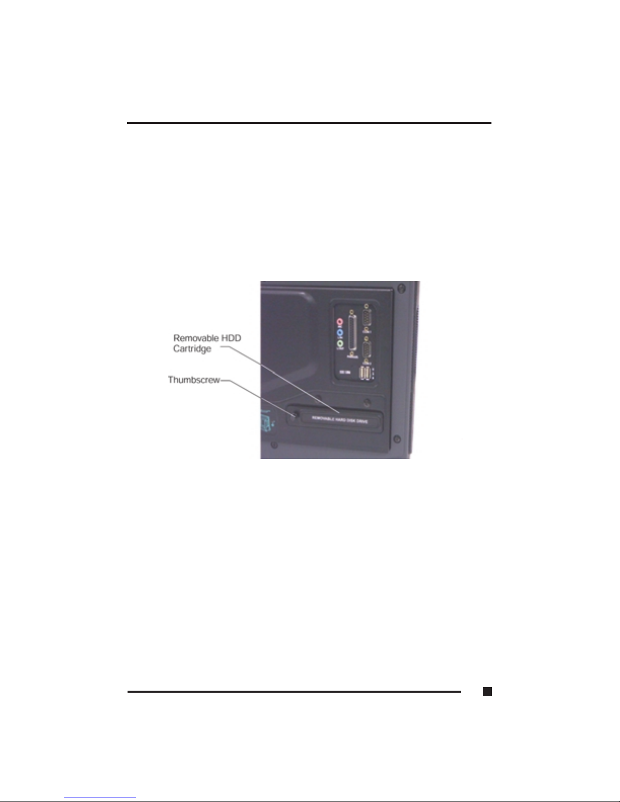
Figure 4.1 Removable Hard Disk Drive Option
4 ■Display & Drives
4.4
Page 84

Floppy Disk Drive
The FlexPAC is equipped with a standard 1.44MB, 3.5-inch floppy disk drive.
It can store up to 1.44MB of data. The floppy disk drive is located below the
flat-panel display, in the lower right-hand corner of the FlexPAC. It is
positioned to the right of the CD-ROM (see Figure 4.2). The keyboard must
be moved to the side when inserting or ejecting a floppy diskette.
1. Optional PCMCIA/CardBus Socket
2. CD-ROM Drive/Optional CD-RW
3. Floppy Disk Drive
Figure 4.2 System Peripherals
4 ■Display & Drives
4.5
Page 85

How to Use the CD-ROM
The following section explains the main features on the CD-ROM, how to
load and remove a CD-ROM disk and manually ejecting a CD. The CD-ROM
has the following features:
■
Eject Button - The rectangular shaped button is used to eject the CD tray
out from the CD-ROM.
■
Status LED - The status LED illuminates to notify you that the power is
“On” and that the system is busy accessing the CD.
■
Manual Eject Hole - Use this tiny emergency hole during a mechanical
or power failure to manually eject the CD tray out from the CD-ROM.
Loading and Removing a CD-ROM Disk
Use the following procedure to load and remove a CD from the CD-ROM.
Place the keyboard to the side when operating the CD-ROM. If it is not
moved, it can interfere with the ejection of the loading tray.
WARNING: Use care when handling the CD as you can easily scratch the
surface and destroy the data. Hold the CD around the outer
edge or by the center hub.
1. Push in the “Eject” button located on the front panel of the CD-ROM and
the loading tray will eject out (see Figures 4.3 and 4.5, Item 5).
2. Carefully place the CD onto the center hub of the loading tray. Gently
press downwards until it snaps securely in place on the spindle (see
Figure 4.4). Push the loading tray back into place in the CD-ROM.
3. To remove the CD, push in the “Eject” button and the loading tray will
eject back out. Carefully remove the CD from the spindle and push the
loading tray back into place. Store the CD in it’s protective case when not
in use.
NOTE: If your FlexPAC is equipped with an optional CD-RW drive,
software is supplied to facilitate CD burning.
4 ■Display & Drives
4.6
Page 86
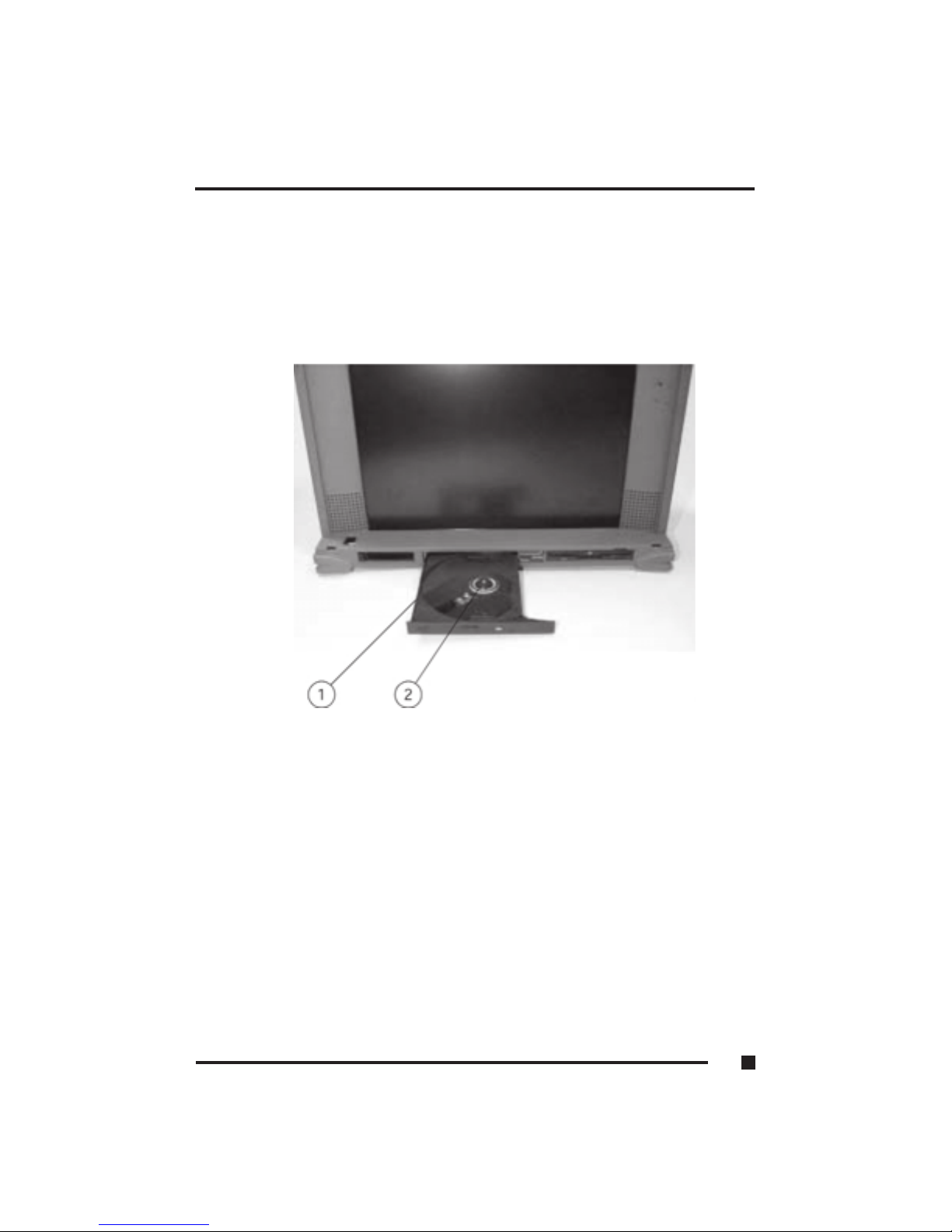
NOTE: Never force a CD into or out of the loading tray.
1. Loading Tray
2. Spindle
Figure 4.3 CD-ROM Loading Tray
4 ■Display & Drives
4.7
Page 87
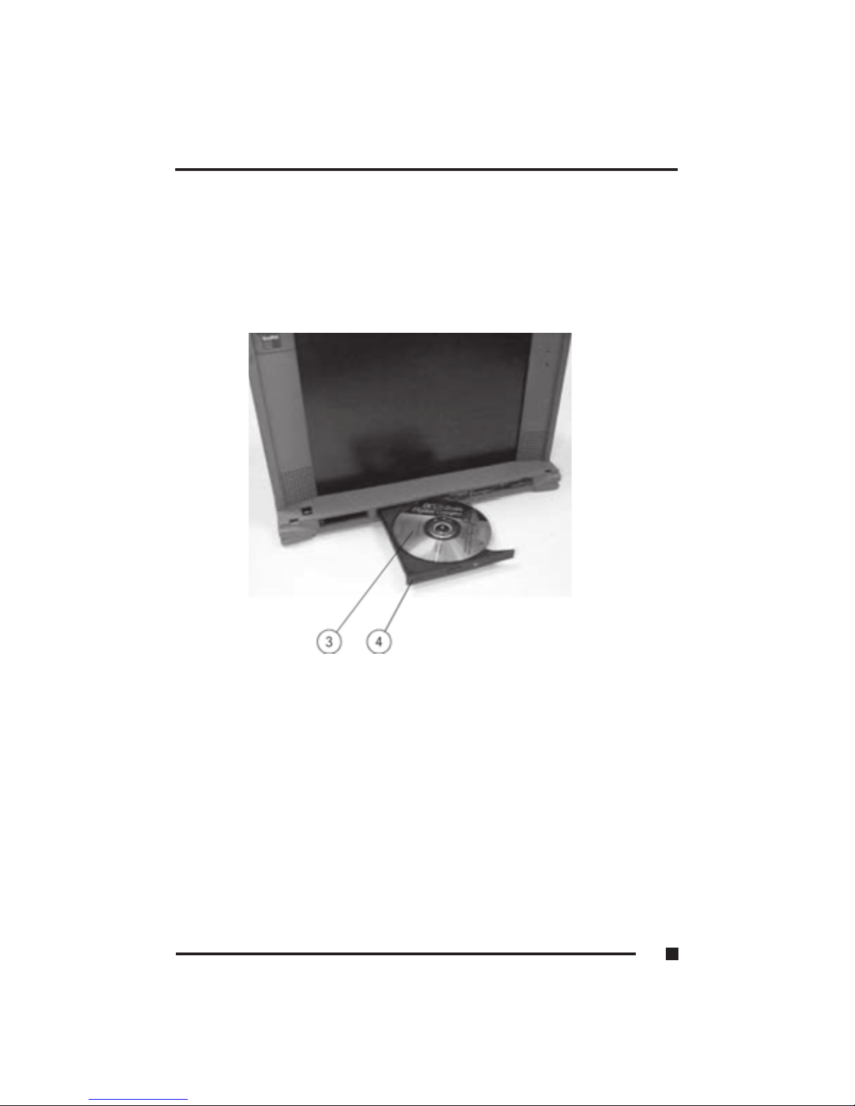
Figure 4.4 Loading a CD
3. Inserted CD
4. Loading Tray
4 ■Display & Drives
4.8
Page 88

The CD-ROM Status LED
The LED indicator, on the CD-ROM, lights up continuously during the seek
cycle and during the transfer of read data to the host. It flashes while the audio
is being played (if applicable). The LED also flashes while the CD-ROM is
completing the following tasks.
1. From POR (Power-On Reset) to the end of TOC (Transfer of Contents) read
2. From tray loading to the end of TOC read (when CD is present)
3. From POR until the end of detecting the CD (no CD present)
4. From tray loading until the end of detecting the CD (no CD present)
5. If a CD error occurs, flashing continues until the CD is ejected. If there is a
hardware problem, flashing continues until the power is switched “Off.”
Manual Ejection of the CD-ROM Disk
The FlexPAC must be powered “On” for normal CD insertion and removal. If
you need to eject a CD during a power failure, or some other type of
mechanical failure, it can be done manually by hand. First, disconnect the
power cord. Then, carefully insert a straightened paper clip or similar thin
pointed tool into the emergency “Manual Eject Hole.” It is located to the right
of the LED on the frontpanel of the CD-ROM drive (see Figure 4.5,Item7).
Push the paper clip inwards until it stops with a click, and the CD-ROM tray
will then eject out.
4 ■Display & Drives
4.9
Page 89
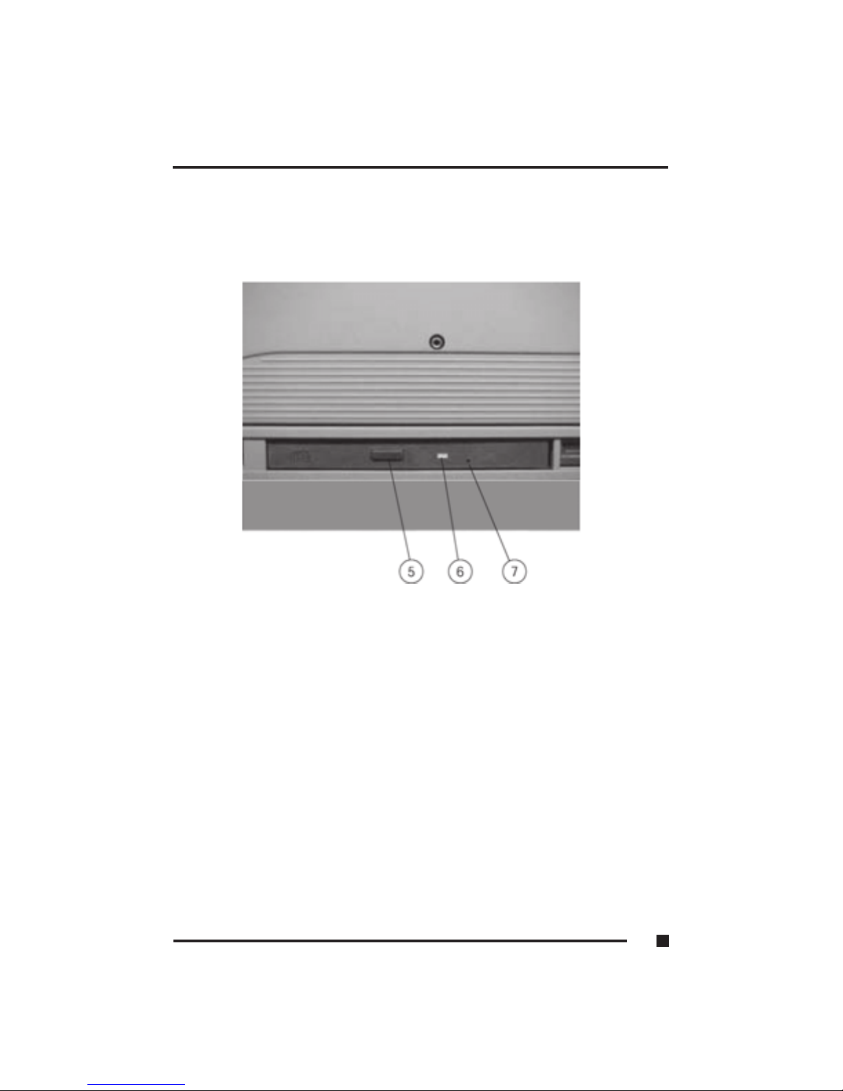
Figure 4.5 CD-ROM Manual Eject Hole
5. Eject Button
6. Status Indicator LED
7. Manual Eject Hole
4 ■Display & Drives
4.10
Page 90

5
Expanding the
FlexPAC
Page 91

EXPANDING THE FLEXPAC
The FlexPAC portable computer provides the expandability of a desktop
system in a convenient all-in-one package. It has four open PCI add-in card
slots and an can be equipped with an optional PCMCIA/Cardbus socket. This
chapter covers the following sections:
■
Opening Up the FlexPAC
■
Installation of Add-In Cards
■
Installation of PC Cards
Before You Begin
Be sure to read this section before you remove the outer casing of the FlexPAC.
The system contains components that can be damaged by electrostatic discharge.
Listed below are some general precautions you should take to minimize
electrostatic discharge when opening up the FlexPAC.
•Always work in a static-free area.
•Before handling any assemblies, discharge your body by touching a
grounded metal object.
•Handle all add-in cards by their edges. Do not touch the components
unless absolutely necessary and avoid touching the gold-edged connectors.
•Whenever possible, use electrostatic wrist straps when handling any
sensitive components.
5 ■Expanding the FlexPAC
5.1
Page 92

Opening Up the FlexPAC
When installing add-in cards into the FlexPAC, the outer casing and the card
retention plate must be removed. This section provides precautions and
procedures necessary for installing and removing add-in cards. The memory
modules are not user accessible. The FlexPAC must be returned to Kontron,
or a Kontron approved service center, for a memory upgrade. Contact
Kontron technical support for assistance.
WARNING: Disassembling the FlexPAC, other than for add -in card install ation,
will void the warranty.
Removing the Outer Casing
A 3mm hex driver is needed to remo ve the outer casing from the FlexPAC.
1. Turn the power switch“Off.” Disconnect the power cord and any other
external device cables connected to the system.
2. Always close the keyboard up against the main unit when opening up the
FlexPAC. This will protect the keyboard and the screen from receiving any
damage when removing the outer casing.
3. Place the unit face down on a flat, sturdy surface. The rear panel will be
facing upwards.
4. Using a 3mm hex driver, remove the six M4 hex screws securing the rear
panel of the unit (see Figures 5.1 & 5.2).
5. Gently slide the outer casing up and away from the main chassis (see
Figure 5.1).
5 ■ Expanding the FlexPAC
5.2
Page 93

Figure 5.1 Rear Panel M4 Hex Screws (6 each)
Figure 5.2 Remove the Outer Casing
5 ■Expanding the FlexPAC
5.3
Page 94

Add-In Card Expansion
For added expansion, the FlexPAC provides four PCI slots. The add-in card
slots are mounted on a passive backplane which sits at a 90 angle from the
system board. Any size card, up to the maximum PCI specified standard can
be used (XT or AT height and anywhere from half to full length).
Card Retaining Foam Blocks
Because the FlexPAC is a portable workstation, the add-in cards must be
properly installed and securely retained to prevent movement during
transport. The units are shipped from the factory with a stationary card
retaining foam block attached underneath the card retention plate (see Figure
5.7). It holds the full length system board firmly in place. It will also secure
and hold in place any additional full-length add-in cards you may install. An
extra foam block is provided to use as needed. It can be used for securing
multiple sized cards or as a replacement for the original. Placement of the
spare foam block is determined by the need, size and location of the cards.
Add-In Card Installation
The outer casing and the card retention plate must be removed to access
the add-in card slots. A 3mmhex driver is needed to remove the outer casing
and a small size phillips-head screwdriver is needed for the add-in card
installation. Use the following procedure to install an add-in card.
1. Make sure the system is disconnected and powered “Off.” Remove the
outer casing (see “Removing the Outer Casing” ). Place the system back
in an upright position with the display facing you.
2. Using a small size phillips-head screwdriver, remove the two upper
screws securing the card retention plate (see Figure 5.3) Then, use the
phillips-head screwdriver to remove the two screws securing the right
side of the card retention plate, above the I/O opening (see Figure 5.4).
3. Carefully lift up the right side (above the I/O opening) of the card
retention plate first (see Figure 5.5), and then the left side, disengaging
the notched end from the mating slots. Remove the card retention plate
from the main unit.
5 ■Expanding the FlexPAC
5.4
Page 95

4. Determine the add-in card placement slot. Remove the single screw
securing the adjacent I /O slot cover (see Figures 5.6). Lift up and remove
the I /O slot cover from the expansion opening, saving the screw for later
use (see Figure5.7).
5. Guide the add-in card into the expansion slot. Using both hands, press it
down evenly into the socket (see Figure 5.8). Make sure the card is firmly
seated (see Figure 5.9).
6. Replace the single screw into the I /O bracket, to secure the add-in card
(see Figure 5.9).
7. If needed, use the extra supplied card retaining foam block to hold
multiple sized add-in cards in place. Peel off the tape to expose the
adhesive strip. Strategically attach it across the card retention plate,
parallel with the other stationary foam block.
NOTE: Do not position the self-adhesive foam block over the air vents
on the card retention plate (see Figure 5.10). Doing so, will
prevent proper airflow which may damage the FlexPAC.
8. Place the card retention plate back into the FlexPAC. First engage the
notched ends, on the left side, into their mating slots, then lower the right
end of the card retention plate, back into place. Make sure the foam block
is correctly aligned across the cards.
9. Using the phillips-head screwdriver, replace the two screws to secure the
right side of the card retention plate. Then replace the two upper screws
on the card retention plate (see Figure 5.3).
10. Place the unit face down on a flat, sturdy surface. The rear panel will be
facing upwards. Carefully slide the outer casing back onto the main
chassis.
11. Using the 3mm hex driver, replace the six rear panel screws. Do not over
tighten them.
5 ■Expanding the FlexPAC
5.5
Page 96
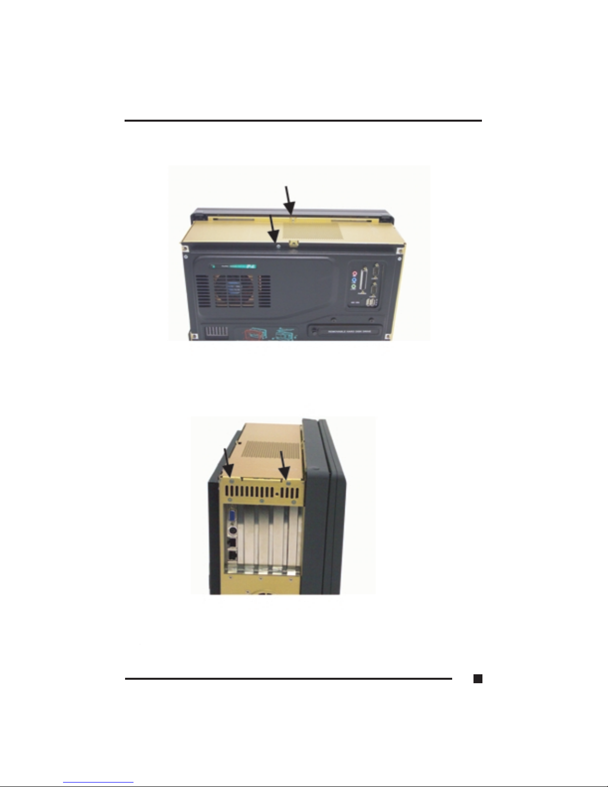
Figure 5. 3 Two Upper Card Retention Plate Screws
Figure 5. 4 Two Card Retention Plate Screws
5 ■Expanding the FlexPAC
5.6
Page 97
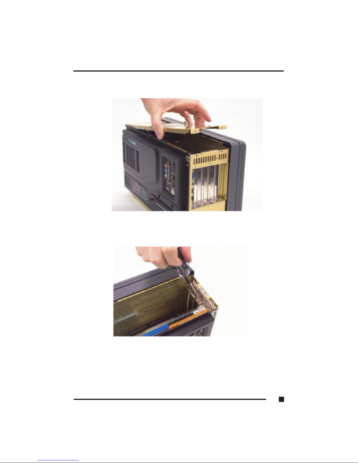
Figure 5. 5 Lift Up the Card Retention Plate
Figure 5. 6 Expansion Slot Cover - Single Screw Removal
5 ■Expanding the FlexPAC
5.7
Page 98
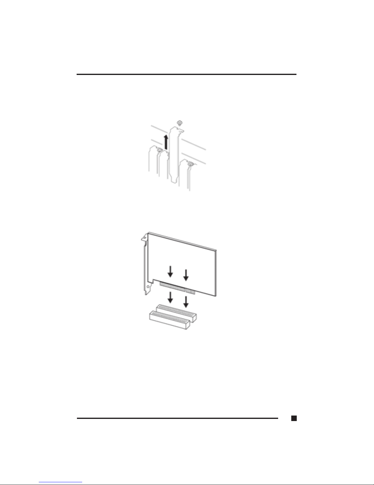
Figure 5.7 Removing an Expansion Slot Cover
Figure 5.8 Inserting an Add-in Card
5 ■Expanding the FlexPAC
5.8
Page 99
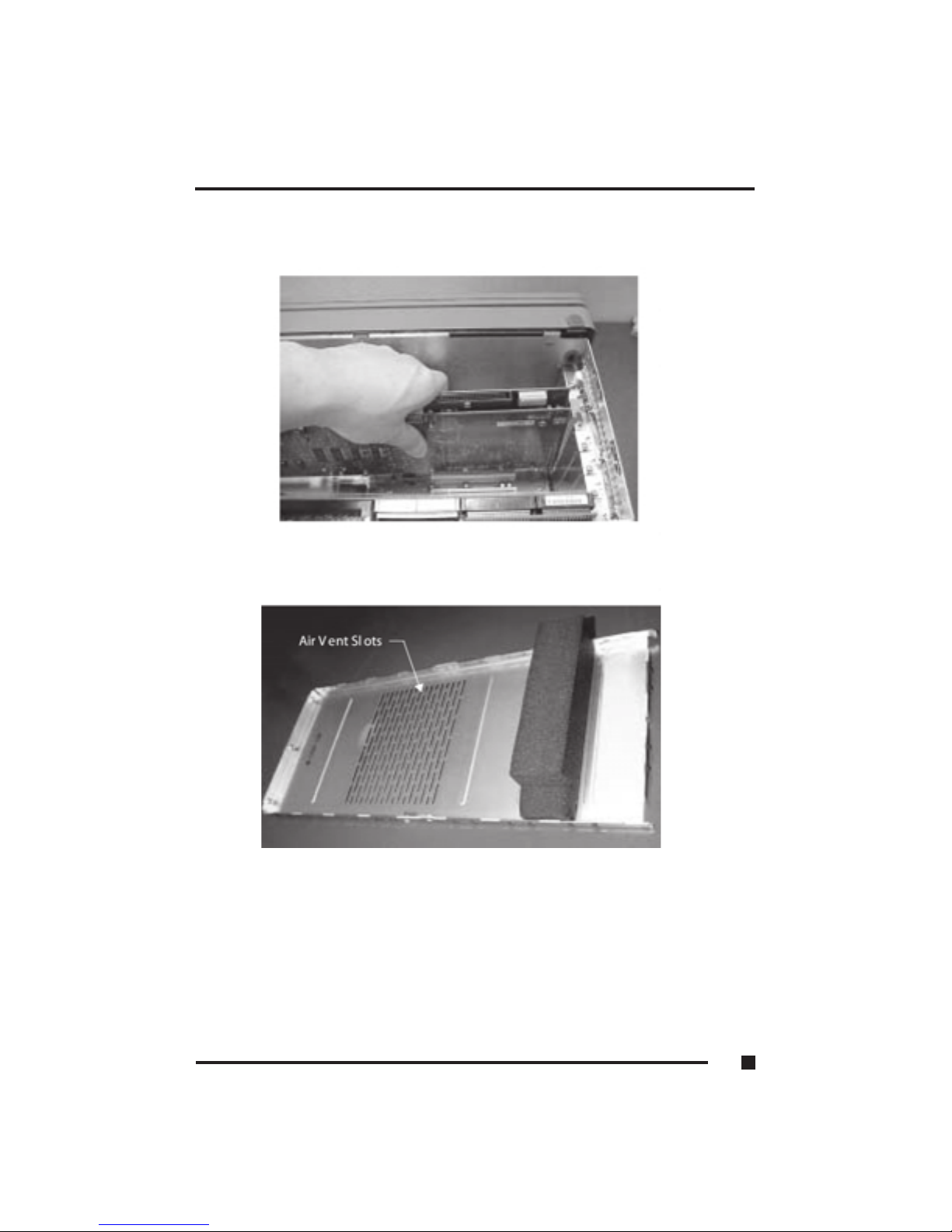
Figure 5.9 Securing the Add-in Card
Figure 5.10 Fixed Card Retaining foam block
5 ■Expanding the FlexPAC
5.9
Page 100
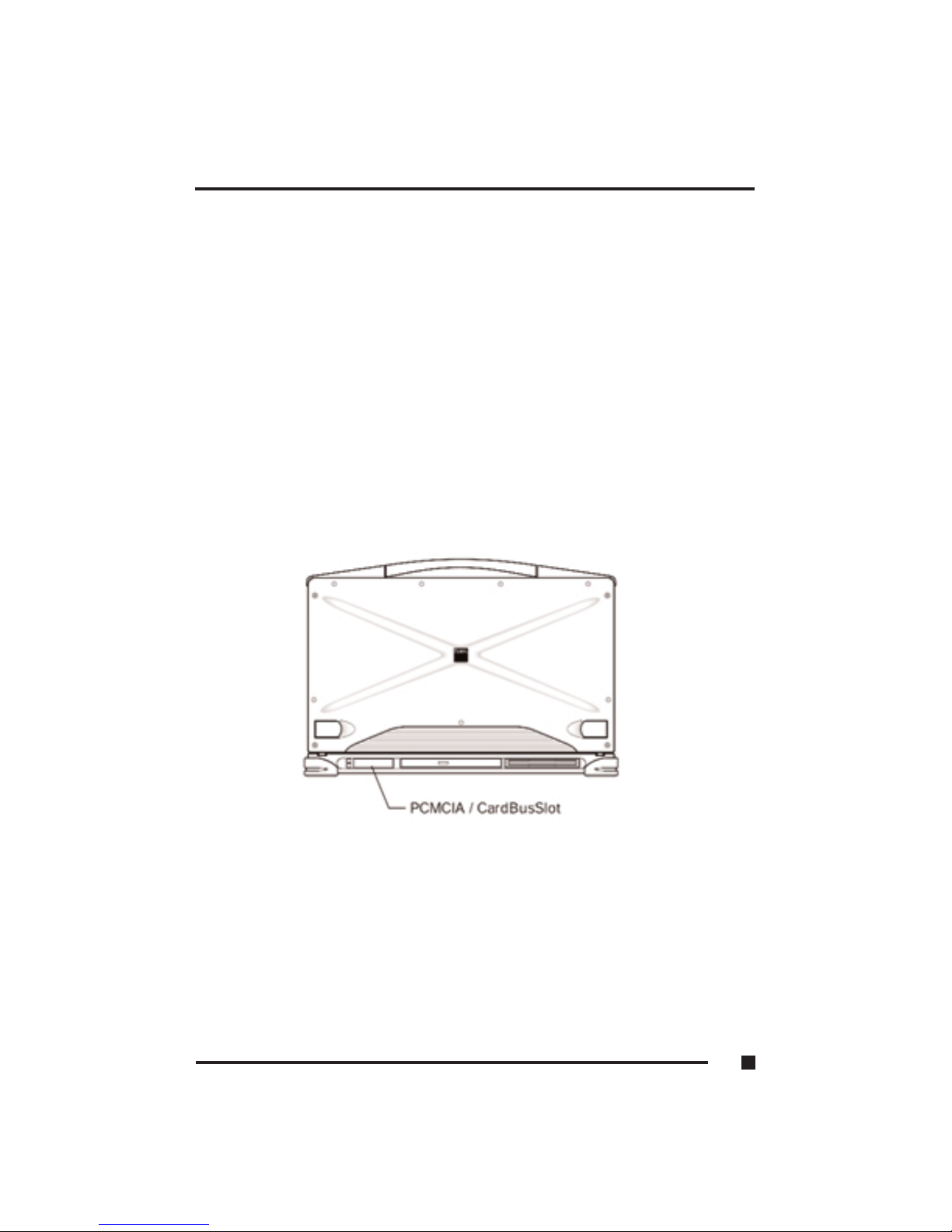
Optional PCMCIA Cards
The FlexPAC can be fitted with an optional PCMCIA/CardBus socket for
added expansion. The PCMCIA/CardBus socket accepts either two type II or
one type III PC cards. Since both type II slots are co-located in the same
opening, one type III PC card can be inserted instead of two type II PC cards.
The type III PC card occupies both slots. The FlexPAC supports “hot
insertion.” You can insert the PC card into the socket while the system is
powered “On.” The PCMCIA/CardBus socket is located on the front side, in
the lower left hand corner, next to the CD-ROM (see Figure 5.8).
1. With the insert marking facing upwards, slide the PC card firmly into the
socket until it is in place.
2. To remove the upper PC card: Press the upper eject button.
To remove the lower PC card: Press the lower eject button.
Figure 5.8 Optional PCMCIA Socket
5 ■Expanding the FlexPAC
5.10
 Loading...