

Page 1
USER GUIDE
www.kontron.com // 1
FlatView
Doc. Rev. 1.6
Doc. ID: 1061-6343
Page 2

FlatView – Rev. 1.6
www.kontron.com // 2
This page has been intentionally left blank
Page 3

FlatView – Rev. 1.6
www.kontron.com // 3
FLATVIEW
- USER GUIDE
Disclaimer
Kontron would like to point out that the information contained in this user guide may be subject to alteration,
particularly as a result of the constant upgrading of Kontron products. This document does not entail any guarantee
on the part of Kontron with respect to technical processes described in the user guide or any product characteristics
set out in the user guide. Kontron assumes no responsibility or liability for the use of the described product(s),
conveys no license or title under any patent, copyright or mask work rights to these products and makes no
representations or warranties that these products are free from patent, copyright or mask work right infringement
unless otherwise specified. Applications that are described in this user guide are for illustration purposes only.
Kontron makes no representation or warranty that such applications will be suitable for the specified use without
further testing or modification. Kontron expressly informs the user that this user guide only contains a general
description of processes and instructions which may not be applicable in every individual case. In cases of doubt,
please contact Kontron.
This user guide is protected by copyright. All rights are reserved by Kontron. No part of this document may be
reproduced, transmitted, transcribed, stored in a retrieval system, or translated into any language or computer
language, in any form or by any means (electronic, mechanical, photocopying, recording, or otherwise), without the
express written permission of Kontron. Kontron points out that the information contained in this user guide is
constantly being updated in line with the technical alterations and improvements made by Kontron to the products
and thus this user guide only reflects the technical status of the products by Kontron at the time of publishing.
Brand and product names are trademarks or registered trademarks of their respective owners.
©2017 by Kontron AG
Kontron AG
Lise-Meitner-Str. 3-5
86156 Augsburg
Germany
www.kontron.com
Page 4

FlatView – Rev. 1.6
www.kontron.com // 4
High Risk Applications Hazard Notice
THIS DEVICE AND ASSOCIATED SOFTWARE ARE NOT DESIGNED, MANUFACTURED OR INTENDED FOR USE
OR RESALE FOR THE OPERATION OF NUCLEAR FACILITIES, THE NAVIGATION, CONTROL OR
COMMUNICATION SYSTEMS FOR AIRCRAFT OR OTHER TRANSPORTATION, AIR TRAFFIC CONTROL, LIFE
SUPPORT OR LIFE SUSTAINING APPLICATIONS, WEAPONS SYSTEMS, OR ANY OTHER APPLICATION IN A
HAZARDOUS ENVIRONMENT, OR REQUIRING FAIL-SAFE PERFORMANCE, OR IN WHICH THE FAILURE OF
PRODUCTS COULD LEAD DIRECTLY TO DEATH, PERSONAL INJURY, OR SEVERE PHYSICAL OR
ENVIRONMENTAL DAMAGE (COLLECTIVELY, "HIGH RISK APPLICATIONS").
You understand and agree that your use of Kontron devices as a component in High Risk Applications is entirely at
your risk. To minimize the risks associated with your products and applications, you should provide adequate design
and operating safeguards. You are solely responsible for compliance with all legal, regulatory, safety, and security
related requirements concerning your products. You are responsible to ensure that your systems (and any Kontron
hardware or software components incorporated in your systems) meet all applicable requirements. Unless otherwise
stated in the product documentation, the Kontron device is not provided with error-tolerance capabilities and cannot
therefore be deemed as being engineered, manufactured or setup to be compliant for implementation or for resale as
device in High Risk Applications. All application and safety related information in this document (including application
descriptions, suggested safety measures, suggested Kontron products, and other materials) is provided for reference
only
.
Page 5

FlatView – Rev. 1.6
www.kontron.com // 5
Revision History
Revision Brief Description of Changes Date of Issue
1.6 Converted to the Kontron user guide style 2017-July-18
Terms and Conditions
Kontron warrants products in accordance with defined regional warranty periods. For more information about
warranty compliance and conformity, and the warranty period in your region, visit http://www.kontron.com/termsand-conditions.
Kontron sells products worldwide and declares regional General Terms & Conditions of Sale, and Purchase Order
Terms & Conditions. Visit http://www.kontron.com/terms-and-conditions
.
For contact information, refer to the corporate offices contact information on the last page of this user guide or visit
our website CONTACT US.
Customer Support
Find Kontron contacts by visiting: http://www.kontron.com/support.
Customer Service
As a trusted technology innovator and global solutions provider, Kontron extends its embedded market strengths into
a services portfolio allowing companies to break the barriers of traditional product lifecycles. Proven product
expertise coupled with collaborative and highly-experienced support enables Kontron to provide exceptional peace of
mind to build and maintain successful products.
For more details on Kontron’s service offerings such as: enhanced repair services, extended warranty, Kontron
training academy, and more visit http://www.kontron.com/support-and-services/services
.
Customer Comments
If you have any difficulties using this user guide, discover an error, or just want to provide some feedback, contact
Kontron support
. Detail any errors you find. We will correct the errors or problems as soon as possible and post the
revised user guide on our website.
Page 6

FlatView – Rev. 1.6
www.kontron.com // 6
Symbols
The following symbols may be used in this user guide
DANGER indicates a hazardous situation which, if not avoided,
will result in death or serious injury.
WARNING indicates a hazardous situation which, if not avoided,
could result in death or serious injury.
NOTICE indicates a property damage message.
CAUTION indicates a hazardous situation which, if not avoided,
may result in minor or moderate injury.
Electric Shock!
This symbol and title warn of hazards due to electrical shocks (> 60
V) when touching
products or parts of products
. Failure to observe the precautions indicated and/or
prescribed by the law may endanger your life/health and/or result in d
amage to your
material.
ESD Sensitive Device!
This symbol and title inform that the electronic boards and their components are sensitive
to static electricity. Care must therefore be taken during all handling operations and
inspections of this product in order to ensure product integrity at all times.
HOT Surface!
Do NOT touch! Allow to cool before servicing.
Laser!
This symbol inform of the risk of exposure to laser beam and light emitting devices (LEDs)
from an electrical device. Eye protection per manufacturer notice shall review before
servicing.
This symbol indicates general information about the product and the user guide.
This symbol also indicates detailed information about the specific product configuration.
This symbol precedes helpful hints and tips for daily use.
Page 7

FlatView – Rev. 1.6
www.kontron.com // 7
For Your Safety
Your new Kontron product was developed and tested carefully to provide all features necessary to ensure its
compliance with electrical safety requirements. It was also designed for a long fault-free life. However, the life
expectancy of your product can be drastically reduced by improper treatment during unpacking and installation.
Therefore, in the interest of your own safety and of the correct operation of your new Kontron product, you are
requested to conform with the following guidelines.
High Voltage Safety Instructions
As a precaution and in case of danger, the power connector must be easily accessible. The power connector is the
product’s main disconnect device.
Warning
All operations on this product must be carried out by sufficiently skilled personnel only.
Electric Shock!
Before installing a non hot-swappable Kontron product into a system always ensure that
your mains power is switched off. This also applies to the installation of piggybacks. Serious
electrical shock hazards can exist during all installation, repair, and maintenance operations
on this product. Therefore, always unplug the power cable and any other cables which
provide external voltages before performing any work on this product.
Earth ground connection to vehicle’s chassis or a central grounding point shall remain
connected. The earth ground cable shall be the last cable to be disconnected or the first
cable to be connected when performing installation or removal procedures on this product.
Special Handling and Unpacking Instruction
ESD Sensitive Device!
Electronic products and their components are sensitive to static electricity. Therefore, care
must be taken during all handling operations and inspections of this product, in order to
ensure product integrity at all times.
Do not handle this product out of the products protective enclosure while the product is not used for operational
purposes unless it is otherwise protected.
Whenever possible, unpack or pack this product only at EOS/ESD safe work stations. Where a safe work station is not
guaranteed, it is important for the user to be electrically discharged before touching the product with his/her hands
or tools. This is most easily done by touching a metal part of your system housing.
It is particularly important to observe standard anti-static precautions when changing piggybacks, ROM devices,
jumper settings etc. If the product contains batteries for RTC or memory backup, ensure that the product is not placed
on conductive surfaces, including anti-static plastics or sponges. They can cause short circuits and damage the
batteries or conductive circuits on the product.
Page 8

FlatView – Rev. 1.6
www.kontron.com // 8
Lithium Battery Precautions
If your product is equipped with a lithium battery, take the following precautions when replacing the battery.
Danger of explosion if the battery is replaced incorrectly.
Replace only with same or equivalent battery type recommended by the manufacturer.
Dispose of used batteries according to the manufacturer’s instructions.
General Instructions on Usage
In order to maintain Kontron’s product warranty, this product must not be altered or modified in any way. Changes or
modifications to the product, that are not explicitly approved by Kontron and described in this user guide or received
from Kontron Support as a special handling instruction, will void your warranty.
This product should only be installed in or connected to systems that fulfill all necessary technical and specific
environmental requirements. This also applies to the operational temperature range of the specific board version
that must not be exceeded. If batteries are present, their temperature restrictions must be taken into account.
In performing all necessary installation and application operations, only follow the instructions supplied by the
present user guide.
Keep all the original packaging material for future storage or warranty shipments. If it is necessary to store or ship
the product then re-pack it in the same manner as it was delivered.
Special care is necessary when handling or unpacking the product. See Special Handling and Unpacking Instruction.
Quality and Environmental Management
Kontron aims to deliver reliable high-end products designed and built for quality, and aims to complying with
environmental laws, regulations, and other environmentally oriented requirements. For more information regarding
Kontron’s quality and environmental responsibilities, visit http://www.kontron.com/about-kontron/corporateresponsibility/quality-management.
Disposal and Recycling
Kontron’s products are manufactured to satisfy environmental protection requirements where possible. Many of the
components used are capable of being recycled. Final disposal of this product after its service life must be
accomplished in accordance with the applicable country, state, or local laws or regulations.
WEEE Compliance
The Waste Electrical and Electronic Equipment (WEEE) Directive aims to:
Reduce waste arising from electrical and electronic equipment (EEE)
Make producers of EEE responsible for the environmental impact of their products, especially when the product
become waste
Encourage separate collection and subsequent treatment, reuse, recovery, recycling and sound environmental
disposal of EEE
Improve the environmental performance of all those involved during the lifecycle of EEE
Environmental protection is a high priority with Kontron.
Kontron follows the WEEE directive.
You are encouraged to return our products for proper disposal.
Page 9

FlatView – Rev. 1.6
www.kontron.com // 9
Table of Contents
Symbols ................................................................................................................................................................................................................. 6
For Your Safety .................................................................................................................................................................................................... 7
High Voltage Safety Instructions .................................................................................................................................................................. 7
Special Handling and Unpacking Instruction ............................................................................................................................................ 7
Lithium Battery Precautions .......................................................................................................................................................................... 8
General Instructions on Usage...................................................................................................................................................................... 8
Quality and Environmental Management ................................................................................................................................................. 8
Disposal and Recycling .................................................................................................................................................................................... 8
WEEE Compliance.............................................................................................................................................................................................. 8
Table of Contents ............................................................................................................................................................................................... 9
List of Tables ....................................................................................................................................................................................................... 11
List of Figures ..................................................................................................................................................................................................... 11
1/ Introduction .......................................................................................................................................................................................... 12
2/ General Safety Instructions for IT Equipment .......................................................................................................................... 13
General Safety Instructions ................................................................................................................................................................... 13 2.1.
Cleaning of Display .................................................................................................................................................................................. 13
2.2.
Electromagnetic Compatibility EU ...................................................................................................................................................... 14
2.3.
Electrostatic Discharge (ESD) .............................................................................................................................................................. 14
2.4.
2.4.1. Grounding Methods .............................................................................................................................................................................. 14
3/ Scope of Delivery and Accessories ............................................................................................................................................... 15
3.1.1. Type Label and Product Identification ............................................................................................................................................. 16
4/ Product Description ........................................................................................................................................................................... 17
Product View............................................................................................................................................................................................... 17 4.1.
5/
Technical Data/Environmental Specification ........................................................................................................................... 19
CE Directives and Standards CE Directives ...................................................................................................................................... 20 5.1.
6/
Order Information............................................................................................................................................................................... 21
7/ Mechanical Specification ................................................................................................................................................................ 22
10.4“ Built-in Variant ............................................................................................................................................................................... 22 7.1.
10.4“ Full metal Variant .......................................................................................................................................................................... 22
7.2.
12.1“ Built-in Variant ................................................................................................................................................................................ 23
7.3.
12.1“ Full metal Variant........................................................................................................................................................................... 23
7.4.
15.0“ Built-in Variant ............................................................................................................................................................................... 24
7.5.
15.0“ Full metal Variant .......................................................................................................................................................................... 24
7.6.
15.6“ Built-in Variant ............................................................................................................................................................................... 25
7.7.
15.6“ Full metal Variant .......................................................................................................................................................................... 25
7.8.
17.0“ Built-in Variant ............................................................................................................................................................................... 26
7.9.
17.0“ Full metal Variant ........................................................................................................................................................................ 26
7.10.
18.5“ Built-in Variant .............................................................................................................................................................................. 27
7.11.
18.5“ Full metal Variant ........................................................................................................................................................................ 27
7.12.
19.0“ Built-in Variant ............................................................................................................................................................................. 28
7.13.
19.0“ Full metal Variant ........................................................................................................................................................................ 28
7.14.
21.5“ Built-in Variant .............................................................................................................................................................................. 29
7.15.
21.5“ Full metal Variant ........................................................................................................................................................................ 29
7.16.
23.8” Built –in Variant ........................................................................................................................................................................... 30
7.17.
23.8” Full metal Variant ....................................................................................................................................................................... 30
7.18.
Page 10

FlatView – Rev. 1.6
www.kontron.com // 10
8/ Installation and Start ........................................................................................................................................................................ 31
Mounting Instructions (Built-in variant only) ................................................................................................................................. 31 8.1.
Startup Procedure ................................................................................................................................................................................... 32
8.2.
9/
Connectors ........................................................................................................................................................................................... 33
Input Power Connector (PWR) ............................................................................................................................................................. 33 9.1.
DVI Connector ........................................................................................................................................................................................... 34
9.2.
Display Port (DP) Connector ................................................................................................................................................................ 34
9.3.
USB Client Connector (Type B)............................................................................................................................................................ 34
9.4.
OSD (On Screen Display) Keypad ....................................................................................................................................................... 35
9.5.
9.5.1. Power Button ......................................................................................................................................................................................... 35
9.5.2. LED Power Indicator ............................................................................................................................................................................ 35
9.5.3. Up Button and Down Button ............................................................................................................................................................ 35
9.5.4. Select Button ......................................................................................................................................................................................... 35
9.5.5. Menu Button .......................................................................................................................................................................................... 35
OSD Menu ................................................................................................................................................................................................... 36 9.6.
9.6.1. Main Menu: Input Select ..................................................................................................................................................................... 36
9.6.2. Main Menu: Image Adjustments ..................................................................................................................................................... 37
9.6.3. Main Menu: Color Adjustment ......................................................................................................................................................... 38
9.6.4. Main Menu: OSD Settings .................................................................................................................................................................. 40
9.6.5. Main Menu: System Settings ............................................................................................................................................................ 42
10/ Technical Support ............................................................................................................................................................................. 44
Warranty ................................................................................................................................................................................................... 44 10.1.
Returning Defective Merchandise ................................................................................................................................................... 45
10.2.
Appendix A: List of Acronyms ...................................................................................................................................................................... 46
About Kontron .................................................................................................................................................................................................. 47
Page 11

FlatView – Rev. 1.6
www.kontron.com // 11
List of Tables
Table 1: Scope of Delivery .............................................................................................................................................................................. 15
Table 2: Accessories ........................................................................................................................................................................................ 15
Table 3: Technical Data .................................................................................................................................................................................. 19
Table 4: General Technical Data and Environmental Specification................................................................................................ 20
Table 5: Input Power Connector Pinout ................................................................................................................................................... 33
Table 6: DVI Connector Pinout ..................................................................................................................................................................... 34
Table 7: DP Connector Pinout ...................................................................................................................................................................... 34
Table 8: USB Client Connector Pinout ....................................................................................................................................................... 34
Table 9: LED Power Indicator’s Color Description ................................................................................................................................ 35
Table 10: List of Acronyms ........................................................................................................................................................................... 46
List of Figures
Figure 1: FlatView Series ................................................................................................................................................................................ 12
Figure 2: Type Label ......................................................................................................................................................................................... 16
Figure 3: Front View Description ................................................................................................................................................................. 17
Figure 4: Bottom View Description – built-in variant ........................................................................................................................... 17
Figure 5: Bottom View Description – full metal variant ...................................................................................................................... 18
Figure 6: Fastening Clips and Screws ........................................................................................................................................................ 31
Figure 7: Clamping Bracket with Screw..................................................................................................................................................... 31
Figure 8: Clamping Bracket Insertion ......................................................................................................................................................... 31
Figure 9: Fastening the Clamping Bracket ............................................................................................................................................... 31
Figure 10: Clamping Bracket Positions ..................................................................................................................................................... 32
Figure 11: FlatView Connector Panel ......................................................................................................................................................... 33
Figure 12: OSD Keys ......................................................................................................................................................................................... 35
Page 12

FlatView – Rev. 1.6
www.kontron.com // 12
1/ Introduction
With its FlatView Industrial Monitor series, Kontron offers high mechanical flexibility with respect to the design. With a
full metal housing it can be installed as a stand-alone with VESA 75/75 or 100/100, as well as a built-in solution. All
models feature an easy-clean, anti-glare and scratch-proof IP65 protected front glass. The front options offer a choice
between either PCAP touch, resistive touch, or protection glass. The FlatView monitors are available from 10.1" to 23.8",
that can be operated in both landscape and portrait format.
The FlatView enables intuitive multi-touch access to real-time actionable data, making it the perfect fit for SCADA and
Manufacturing Execution Systems (MES), process visualization and other control applications. The modular design can
be easily customized for a broad variety of applications, thus making it suitable across all industries that require
visualization and processing of data.
The built-in version is installed directly on the machine or in a command or control console. The FlatView is servicefriendly for the user and is designed for a long life cycle.
Figure 1: FlatView Series
Page 13

FlatView – Rev. 1.6
www.kontron.com // 13
2/ General Safety Instructions for IT Equipment
Please read this carefully and observe the instructions for your own safety and correct use of the product. This chapter
also contains information on approval and interference suppression of your product. Observe the warnings and
instructions on the product and in the user guide.
General Safety Instructions 2.1.
In order to maintain condition and ensure safe operation, observe the instructions and warnings contained in this user
guide.
The product must be used in accordance with the instructions for use.
The electrical installations in the room must correspond to the requirements of the local (country-specific)
regulations.
Take care that there are no cables, particularly power cables, in areas where persons can trip over them.
Only use the power cord supplied.
Do not use damaged power cords.
For DC power connection:
The DC power source should be able to be switched off and switched on via an isolating switch.
The unit is only completely disconnected from the DC main power source, when the DC power cord is
disconnected either from the power source or the unit. Therefore, the DC power cord and its connectors must
always remain easily accessible.
For AC power connection via external AC/DC adapter:
The main power cable of the external AC/DC adapter serves as a disconnecting device. For this reason, the
outlet of the AC power source must be located near the product and be easily accessible.
Do not place the product in direct sunlight, near heat sources or in a damp place. Make sure the product has
adequate ventilation.
Only devices and components that fulfill the requirements of an SELV circuit (safety extra low voltage) in
accordance with EN60950 may be connected to the interfaces of the system.
All plugs on the connection cables must be screwed or locked to the housing.
The product generates heat during operation. Make sure it is adequately ventilated. Do not cover the air intake and
exhaust openings of the product.
Maintenance or repair on the open product may only be carried out by qualified personnel authorized by Kontron,
that are aware of the associated dangers.
When accessing internal components the product must be switched off and disconnected from the power source.
Cleaning of Display 2.2.
Clean the surface of your display with a dry and clean cloth to eliminate dust and particles of dirt.
Particles may scratch the surface. Do not apply any pressure.
Use commercially available glass cleaner.
Page 14

FlatView – Rev. 1.6
www.kontron.com // 14
Electromagnetic Compatibility EU 2.3.
This product is in conformity with the protection requirements of EU Council Directive 2004/108/EC on the
approximation of the laws of the Member States relating to electromagnetic compatibility. If the user modifies and/or
adds to the equipment (e.g. installation of add-on cards) the prerequisites for the CE conformity declaration, (safety
requirements) may no longer apply.
EN 61000-6-3 Generic standard Emission standard for residential, commercial and light-industrial
environments (Emission)
EN 55022/B Emission of Information technology equipment, radio disturbance characteristics and limits
and methods of measurement
EN 55024
ITE - Immunity characteristics - Limits and methods of measurement
Electrostatic Discharge (ESD) 2.4.
A sudden discharge of electrostatic electricity can destroy static-sensitive devices or micro-circuitry. Therefore, proper
packaging and grounding techniques are necessary precautions to prevent damage.
Always take the following precautions:
ESD Sensitive Device!
Keep electrostatic sensitive parts in their containers until they arrive at the ESD-safe
workplace.
Always be properly grounded when touching a sensitive board, component, or
assembly.
For more Information, see the Special Handling and Unpacking Instruction within this user guide and Chapter 2.4.1
Grounding Methods below.
2.4.1. Grounding Methods
The following measures help to avoid electrostatic damages to the device:
Cover workstations with approved antistatic material. Always wear a wrist strap connected to the workplace, as
well as properly grounded tools and equipment.
Use antistatic mats, heel straps, or air ionizers for more protection.
Always handle electrostatically sensitive components by their edge or by their casing.
Avoid contact with pins, leads, or circuitry.
Turn off power and input signals before inserting and removing connectors or connecting test equipment.
Keep the work area free of non-conductive materials such as ordinary plastic assembly aids and styrofoam.
Use field service tools such as cutters, screwdrivers, and vacuum cleaners that are conductive.
Always place drives and boards with the PCB-assembly-side down on the foam.
Page 15

FlatView – Rev. 1.6
www.kontron.com // 15
3/ Scope of Delivery and Accessories
Components delivered with the FlatView and accessories available for the FlatView are described below.
Check that your delivery is complete, and contains the items below (according to the ordered unit configuration). If you
discover damaged or missing items, contact your dealer.
Table 1: Scope of Delivery
Qty. Part Number Part Description
1 For order information, see
Chapter 6/ Order Information.
FlatView
1
EM21-100065-0 (10.4"/12.1")
EM21-100066-0 (15.0"/15.6")
EM21-100067-01 (17.0"/19.0")
EM21-100068-01 (18.5"/23.8")
EM21-100069-01 (21.5")
Mounting set with clamps and screws,
only for built-in variant
Table 2: Accessories
Qty. Part Number Part Description
1 EE04-100001-01 Phoenix Power Subcon w/ housing
1 840-0059 EU-Powercord 1,8m
1 ER40-100001-01 Set Power supply 24VDC /w Phoenix
Connector
1 PR22-100004-01 Adapter Kabel HDMI - DisplayPort,
20cm, 4K aktiv,
Delock: 62607
1 PR22-100005-01 Adapter HDMI - DisplayPort 1.2, 4K aktiv,
Delock: 65573
1 PR22-100006-01 Adapter DVI-D - DisplayPort 1.1, Delock:
65257
1 PR22-100007-01 Adapter VGA - DisplayPort 1.1, Delock:
65567
Page 16

FlatView – Rev. 1.6
www.kontron.com // 16
Qty. Part Number Part Description
1 PR22-100008-01 Adapter DVI-I – HDMI, Delock: 65467
1 840-0758 Display-Port cable 1,8m
1 840-0759 DP cable 3m
1 840-0760 DP cable 5m
1 840-0598 Adapter VGA / DVI
1 840-0039
VGA/SVGA cable 1,8m/2,0m
1 840-0273 USB-cable 1,8m, Type A – Type B
1 840-0134 DVI-cable 2m
3.1.1. Type Label and Product Identification
Product and Package Label, size 85 mm x 35mm, polyester matt silver.
Figure 2: Type Label
Technical Data
depending on device
Short Description
Barcode Part Number
Part Number
Series Number (11 numeric digits)
Barcode Series Number
Certification Print
depending on device
Internal Use Only
Page 17

FlatView – Rev. 1.6
www.kontron.com // 17
4/ Product Description
Product View 4.1.
Figure 3: Front View Description
1 TFT Display with resistive touch
2 Front plate
Figure 4: Bottom View Description – built-in variant
1
Display Port connector
2 OSD keypad
3 Power LED
4 LAN (option only)
5 LPC (option only)
6
Rear cover
7 Mounting clips
8 Sealing cord
9 Power connector
10 USB connector
11 DVI connector
2
1 8 7
6 5 4
3
2
1
11
10
9
Page 18

FlatView – Rev. 1.6
www.kontron.com // 18
Figure 5: Bottom View Description – full metal variant
1 Display Port connector
2 OSD keypad
3 Power LED
4 LAN (option only)
5 LPC (option only)
6 Rear cover
7 Power connector
(Insert for Power Supply)
8 USB connector
9 DVI connector
1
4
5
6
2
3
7
8
9
Page 19

FlatView – Rev. 1.6
www.kontron.com // 19
5/ Technical Data/Environmental Specification
Table 3: Technical Data
Display Size 10.4“ 12.1“ 12.1“ XGA 15.0“
Display Manufacturer
Innolux Innolux Innolux Innolux
Display Type
G104AGE-L02 G121AGE-L03 G121X1-L03 G150XGE-L04
Resolution
800x600 800x600 1024x768, XGA 1024x768
Format
4:3 4:3 4:3 4:3
Contrast Ratio
700:1 1500:1 700:1 700:1
Brightness
400 cd 450 cd 600 cd 400 cd
Angle View
H160° / V140° H178° / V178° H160°/ V140° H160° / V140°
Colors
16.7 million 16.7 million 16.2 million 16.7 million
LED Lifetime (> 50%, 25°C)
> 50.000 h > 50.000 h > 50.000 h > 50.000 h
Dimensions (WxHxD-mm)
297 x 244 x 65 338 x 277 x 65 338 x 277 x 65 396 x 312 x 69
Weight
~ 3,9 kg ~ 4,7 kg ~ 4,7 kg ~ 6,4 kg
Touch Options
Protection glass / PCAP / Resistive
Technical Data - continued
Display Size 15.6“ 15.6“ Full HD 17.0“ 18.5“
Display Manufacturer
Innolux AUO AUO Innolux
Display Type
G156BGE-L01 G156HTN02.0 G170EG01V1 G185BGE-L01
Resolution
1366x768, HD 1920x1080, Full HD 1280x1024 1366x768, HD
Format
16:9 16:9 5:4 16:9
Contrast Ratio
500:1 500:1 800:1 1000:1
Brightness
300 cd 400 cd 350 cd 300 cd
Angle View
H160° / V160° H140° / V120° H160° / V140° H178° / V170°
Colors
16.7 million 16.2 million 16.7 million 16.7 million
LED Lifetime (> 50%, 25°C)
> 50.000 h > 50.000 h > 50.000 h > 50.000 h
Dimensions (WxHxD-mm)
432 x 281 x 74 432 x 281 x 74 427 x 360 74 500 x 321 x 74
Weight
~ 6,7 kg ~ 6,7 kg ~ 7,8 kg ~ 8,6 kg
Touch Options
Protection glass / PCAP / Resistive
Technical Data -continued
Display Size 19.0“ 21.5“ 23.8“
Display Manufacturer
AUO AUO AUO
Display Type
G190ETN01.2 G215HVN01.0 G238HAN01.0
Resolution
1280x1024 1920x1080, Full HD 1920x1080, Full HD
Format
5:4 16:9 16:9
Contrast Ratio
1000:1 3000:1 1000:1
Brightness
350 cd 300 cd 250cd
Angle View
H170° / V160° H178° / V178° H178° / V178°
Colors
16.7 million 16.7 million 16.7 million
LED Lifetime (> 50%, 25°C)
> 50.000 h > 50.000 h > 30.000h
Dimensions (WxHxD-mm)
473 x 396 x 68 575 x 367 x 74 569 x 357 x 69
Weight
~ 9,4 kg ~ 10,7 kg ~ 11,8 kg
Touch Options
Protection glass / PCAP / resistive
Page 20

FlatView – Rev. 1.6
www.kontron.com // 20
Table 4: General Technical Data and Environmental Specification
Fastening VESA 75/75 or 100/100 (full metal housing only);
fastening clips (built-in-variant only)
Color RAL 7021 /black anthracite (full metal housing only)
Video IN 1x DVI, 1x Display Port
I/O Options USB 2.0 (Type B) - client; LPC (Option), LAN (option)
Power Supply 16 VDC -30 VDC Input via Phoenix Connector PSC 1,5/3-F
Cooling Fanless passive cooling
Operating Temperature 0°C - 50°C ambient
Storage Temperature -10°C - 60°C ambient
Operating Altitude Up to 3000 m (9900 ft)
Storage Altitude Up to 5000 m (16500 ft)
Humidity 10%-90% @ 39°C, non condensing
Operating Altitude Up to 3000 m (9900 ft)
Storage Altitude Up to 5000 m (16500 ft)
Certification CE, cULus
Protection Class Front: IP65, Housing IP20
EMC EN55022 class B
CE Directives and Standards CE Directives 5.1.
Low Voltage Directive (Electrical Safety) 2006/95/EC
EMC Directive 2004/108/EC
RoHS II Directives E2011/65/EU
Page 21

FlatView – Rev. 1.6
www.kontron.com // 21
6/ Order Information
Example: EN00-Z41300-01 (FlatView 15.6“ with resistive touch in full metal housing)
EN00-yyyyyy-xx
1. Internal Code (Standard FlatView)
2. Display Size: Z1 = 10.4“
Z2 = 12.1“
Z3 = 15.0“
Z4 = 15.6“
Z5 = 17.0“
Z6 = 18.5“
Z7 = 19.0“
Z8 = 21.5“
ZH= 23.8”
3. Touch Technology: 0 = Without touch, only with protection glass
1 = Touch resistive
2 = Touch PCAP
3 = With protection glass and stainless steel front
4 = Touch resistive and stainless steel front
5 = Touch PCAP and stainless steel front
6= Touch PCAP V2 (low cost)
7 = Protection glass V2 (low cost)
4. Mounting Variant: 3 = Full metal
4 = Built-in-mounting
5. Options: Counted on demand
Possible display options (full HD, XGA, …)
6. Internal Code (Revision)
1
2
5 6 3
4
Page 22

FlatView – Rev. 1.6
www.kontron.com // 22
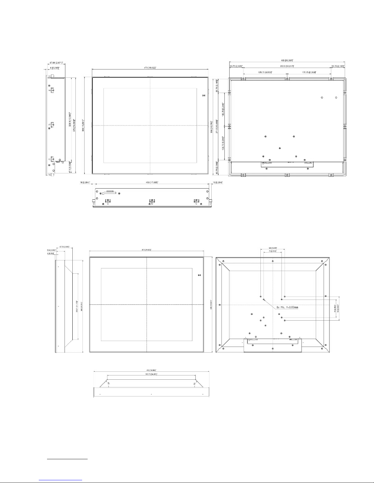
7/ Mechanical Specification
10.4“ Built-in Variant 7.1.
10.4“ Full metal Variant 7.2.
Page 23

FlatView – Rev. 1.6
www.kontron.com // 23
12.1“ Built-in Variant 7.3.
12.1“ Full metal Variant 7.4.
Page 24

FlatView – Rev. 1.6
www.kontron.com // 24
15.0“ Built-in Variant 7.5.
15.0“ Full metal Variant 7.6.
Page 25

FlatView – Rev. 1.6
www.kontron.com // 25
15.6“ Built-in Variant 7.7.
15.6“ Full metal Variant 7.8.
Page 26

FlatView – Rev. 1.6
www.kontron.com // 26
17.0“ Built-in Variant 7.9.
17.0“ Full metal Variant 7.10.
Page 27

FlatView – Rev. 1.6
www.kontron.com // 27
18.5“ Built-in Variant 7.11.
18.5“ Full metal Variant 7.12.
Page 28
FlatView – Rev. 1.6
www.kontron.com // 28
19.0“ Built-in Variant 7.13.
19.0“ Full metal Variant 7.14.
Page 29

FlatView – Rev. 1.6
www.kontron.com // 29
21.5“ Built-in Variant 7.15.
21.5“ Full metal Variant 7.16.
Page 30

FlatView – Rev. 1.6
www.kontron.com // 30
23.8” Built –in Variant 7.17.
23.8” Full metal Variant 7.18.
Page 31

FlatView – Rev. 1.6
www.kontron.com // 31
8/ Installation and Start
Mounting Instructions (Built-in variant only) 8.1.
The FlatView’s built-in variant is designed to be mounted in the user’s application using fastening clips. To mount the
FlatView follow the steps below:
1. Use the fastening clips and screws provided with the FlatView, see Figure 6: Fastening Clips and Screws.
Figure 6: Fastening Clips and Screws
The screws provided are lens head screw Philips M4x12, DIN 7985 - ISO 7045.
To fasten screws, use a Philips head screwdriver.
2. Insert the screw into the clamping bracket provided, to pre-assembly the clamping bracket. The correct direction of
the screw is show in Figure 7: Clamping Bracket with Screw.
Figure 7: Clamping Bracket with Screw
3. Insert the clamping bracket in the housing, as shown in Figure 8: Clamping Bracket Insertion.
Figure 8: Clamping Bracket Insertion
4. Fasten the screw, to fix the clamping bracket to the housing.
Figure 9: Fastening the Clamping Bracket
Page 32

FlatView – Rev. 1.6
www.kontron.com // 32
5. Repeat step 4 for each clamping bracket position, see Figure 10: Clamping Bracket Positions.
Figure 10: Clamping Bracket Positions
Startup Procedure 8.2.
To activate the FlatView, connect the power source to the power connector on the FlatView’s rear side. Alternatively,
use the mating power connector to connect the power cable. For more information see, Chapter 9.1: Input Power
Connector (PWR). When activated the LED power indicator turns green, see Chapter 9.5.2: LED Power Indicator.
Page 33

FlatView – Rev. 1.6
www.kontron.com // 33
9/ Connectors
Figure 11: FlatView Connector Panel
Input Power Connector (PWR) 9.1.
The 3-pin power connector provides the FlatView’s power connection to an appropriate DC main power supply
(24 V DC) via a power cable connection.
Table 5: Input Power Connector Pinout
Pin 1 Pin 3
Pin Signal
1 GND
2 Shield
3 VCC (24 V DC only)
Mating Connector
Mating Connector Description
Phoenix Contact
PSC 1,5/ 3-F
Order# 1841909
Connector panel
Page 34

FlatView – Rev. 1.6
www.kontron.com // 34
DVI Connector 9.2.
Table 6: DVI Connector Pinout
Pin Signal
Pin Signal
Pin Signal
2 Rx2+
10 Rx1+
18 Rx0+
3 GND
11 GND
19 GND
4 NC
12 NC
20 NC
5 NC
13 NC
21 NC
6 SCL
14 +5V
22 GND
7 SDA
15 GND
23 RxC+
8 NC
16 HP
24 RxC-
C1 RED
C3 BLUE
C5 GND
C2 GREEN
C4 HSYNC
C5- GND
Display Port (DP) Connector 9.3.
Table 7: DP Connector Pinout
Pin19 Pin 1
Pin 20 Pin 2
Pin Signal
Pin Signal
1 TX0+
11 GND
2 GND
12 TX3-
3 TX0-
13 GND
4 TX1+
14 GND
5 GND
15 AUX+
6 TX1-
16 GND
7 TX2+
17 AUX-
8 GND
18 HPD
9 TX2-
19 GND
10 TX3+
20 PWR
USB Client Connector (Type B) 9.4.
Table 8: USB Client Connector Pinout
Pin 2 Pin 1
Pin 3 Pin 4
Pin
Signal
1 +USB_VCC
2 USB_D-
3 USB_D+
4 GND
Internally connected to the touch controller. Connect this port to your PC with USB cable part# 840-0273.
Pin 1 Pin 8
Pin 17 Pin 24 C5
Page 35

FlatView – Rev. 1.6
www.kontron.com // 35
OSD (On Screen Display) Keypad 9.5.
Figure 12: OSD Keys
With the self-explanatory OSD, it is possible to modify the settings and control the CRTtoLCD-Controller’s special
features. The OSD uses a number of menus to make changes and turn on or turn off special features. The configuration
can be performed via the OSD-keypad
9.5.1. Power Button
To turn on or turn off the FlatView, press the POWER button.
9.5.2. LED Power Indicator
The Power LED indicates the FlatView’s current power condition.
Table 9: LED Power Indicator’s Color Description
LED Function
Off No Power
Green Active
Yellow Standby
9.5.3. Up Button and Down Button
To Move to the tab, use the UP or DOWN button to move the cursor.
9.5.4. Select Button
To select the tab, press the SELECT button.
9.5.5. Menu Button
To open the OSD menu, press the MENU button.
Page 36

FlatView – Rev. 1.6
www.kontron.com // 36
OSD Menu 9.6.
The OSD main menu setting are located on the left side of the display screen. If selected, the main menu setting is
highlighted in a black box and the sub menu items relating to the selected main menu setting are displayed in the center
of the display screen. If a sub menu item is selected, the sub menu item is highlighted in a black box and the sub menu’s
options are displayed on the right side of the display screen.
9.6.1. Main Menu: Input Select
9.6.1.1. Sub Menu: Main Picture Channel
9.6.1.2. Sub Menu: Scan Inputs
Page 37

FlatView – Rev. 1.6
www.kontron.com // 37
9.6.2. Main Menu: Image Adjustments
9.6.2.1. Sub Menu: Sharpness
9.6.2.2. Sub Menu: Auto Adjust
Only active with other display interfaces than DVI.
9.6.2.3. Sub Menu: Auto Color Adjust
Only active with other display interfaces than DVI.
9.6.2.4. Sub Menu: Clock
Only active with other display interfaces than DVI.
9.6.2.5. Sub Menu: Phase
Only active with other display interfaces than DVI.
9.6.2.6. Sub Menu: Hor. Position
Only active with other display interfaces than DVI.
9.6.2.7. Sub Menu: Ver. Position
Only active with other display interfaces than DVI.
Page 38

FlatView – Rev. 1.6
www.kontron.com // 38
9.6.3. Main Menu: Color Adjustment
9.6.3.1. Sub Menu: Backlight
9.6.3.2. Sub Menu: Brightness
9.6.3.3. Sub Menu: Contrast
Page 39

FlatView – Rev. 1.6
www.kontron.com // 39
9.6.3.4. Sub Menu: Color Temperature
9.6.3.5. Sub Menu: RGB
Not active to select.
9.6.3.6. Sub Menu: Theme
Page 40

FlatView – Rev. 1.6
www.kontron.com // 40
9.6.4. Main Menu: OSD Settings
9.6.4.1. Sub Menu: OSD Timeout
9.6.4.2. Sub Menu: OSD Hor. Pos.
9.6.4.3. Sub Menu: OSD Ver. Pos.
Page 41

FlatView – Rev. 1.6
www.kontron.com // 41
9.6.4.4. Sub Menu: OSD Blend
9.6.4.5. Sub Menu: OSD Orientation
9.6.4.6. Sub Menu: OSD Language
Page 42

FlatView – Rev. 1.6
www.kontron.com // 42
9.6.5. Main Menu: System Settings
9.6.5.1. Sub Menu: Info
9.6.5.2. Sub Menu: Mode Info
9.6.5.3. Sub Menu: Restore user defaults
Not active to select.
Page 43

FlatView – Rev. 1.6
www.kontron.com // 43
9.6.5.4. Sub Menu: Save user defaults
9.6.5.5. Sub Menu: Reset factory defaults
9.6.5.6. Sub Menu: AA Option
Page 44

FlatView – Rev. 1.6
www.kontron.com // 44
10/ Technical Support
For technical support contact our Support department:
E-mail: support@snt-embedded.de
Phone: +49 (0)89 37 00 58 – 0
Make sure you have the following information available when you call:
Product ID Number (PN),
Serial Number (SN)
The serial number can be found on the Type Label, located on the product’s rear side.
For more information see, Chapter 3.1.1 Type Label and Product Identification.
Be ready to explain the nature of your problem to the service technician.
Warranty 10.1.
Due to their limited service life, parts that by their nature are subject to a particularly high degree of wear (wearing
parts) are excluded from the warranty beyond that provided by law. This applies to the CMOS battery, for example.
There is a protection label on your FlatView.
If the product is opened, the warranty is lost.
Page 45

FlatView – Rev. 1.6
www.kontron.com // 45
Returning Defective Merchandise 10.2.
All equipment returned to Kontron must have a Return of Material Authorization (RMA) number assigned exclusively by
Kontron. Kontron cannot be held responsible for any loss or damage caused to the equipment received without an RMA
number. The buyer accepts responsibility for all freight charges for the return of goods to Kontron's designated facility.
Kontron will pay the return freight charges back to the buyer's location in the event that the equipment is repaired or
replaced within the stipulated warranty period. Follow these steps before returning any product to Kontron.
1. Visit the RMA Information website:
http://www.kontron.com/support-and-services/support/rma-information
Download the RMA Request sheet for Kontron Europe GmbH - Augsburg and fill out the form. Take care to include a
short detailed description of the observed problem or failure and to include the product identification Information
(Name of product, Product number and Serial number). If a delivery includes more than one product, fill out the
above information in the RMA Request form for each product.
2. Send the completed RMA-Request form to the given fax or email address at Kontron Europe GmbH - Augsburg.
Kontron will provide an RMA-Number.
3. The goods for repair must be packed properly for shipping, considering shock and ESD protection.
Goods returned to Kontron Europe GmbH in non-proper packaging will be considered as
customer caused faults and cannot be accepted as warranty repairs.
4. Include the RMA-Number with the shipping paperwork and send the product to the following delivery address:
Kontron Europe GmbH
RMA Support
Lise-Meitner-Str. 3-5
86156 Augsburg
Germany
Phone: +49 (0) 821 4086-0
Fax: +49 (0) 821 4086 111
Email: service@kontron.com
Page 46

FlatView – Rev. 1.6
www.kontron.com // 46
Appendix A: List of Acronyms
Table 10: List of Acronyms
API Application Programming Interface
BMC Base Management Controller
CLI Command-Line Interface
COM Computer-on-Module
DP Display Port
DVI Digital Visual Interface
ECC Error Checking and Correction
FRU Field Replaceable Unit
GPU Graphics Processing Unit
HD/HDD Hard Disk /Drive
IOL IPMI-Over-LAN
IOT Internet of Things
IPMI Intelligent Platform Management
Interface
KCS Keyboard Controller Style
KVM Keyboard Video Mouse
LPC Low Pin Count
MEI Management Engine Interface
NCSI Network Communications Services
Interface
OSD On Screen Display
PCIe PCI-Express
PECI Platform Environment Control Interface
RMA Return of Material Authorization
RTC Real Time Clock
SEL System Event Log
SELV Safety Extra Low Voltage
ShMC Shelf Management Controller
SMBus System Management Bus
SMWI System Monitor Web Interface
SOL Serial Over LAN
SSH Secure Shell
TPM Trusted Platform Module
UEFI Unified Extensible Firmware Interface
USB Universal Serial Bus
VGA Video Graphics Array
VLP Very Low Profile
Page 47

FlatView – Rev. 1.6
www.kontron.com // 47
About Kontron
Kontron, a global leader in embedded computing technology and trusted advisor in Internet
of Things (IoT), works closely with its customers, allowing them to focus on their core
competencies by offering a complete and integrated portfolio of hardware, software and
services designed to help them make the most of their applications.
With a significant percentage of employees in research and development, Kontron creates
many of the standards that drive the world’s embedded computing platforms; bringing to
life numerous technologies and applications that touch millions of lives. The result is an
accelerated time-to-market, reduced total-cost-of-ownership, product longevity and the
best possible overall application with leading-edge, highest reliability embedded
technology.
Kontron is a listed company. Its shares are traded in the Prime Standard segment of the
Frankfurt Stock Exchange and on other exchanges under the symbol “KBC”. For more
information, please visit:
http://www.kontron.com/
CORPORATE OFFICES
EUROPE, MIDDLE EAST
& AFRICA
NORTH AMERICA
ASIA PACIFIC
Lise
-Meitner-Str. 3-5
86156 Augsburg
Germany
Tel.: +
49 821 4086-0
Fax: +
49 821 4086-111
info@kontron.com
9477 Waple
s Str,
San Diego
, CA 92121
USA
Tel.: +
1 888 294 4558
Fax: +
1 858 677 0898
info@us.kontron.com
1~2F, 10 Building, No. 8 Liangshuihe 2nd Street,
Economical & Technological Development Zone,
Beijing, 100176, P.R.
China
Tel.:
+ 86 10 63751188
Fax:
+ 86 10 83682438
info@kontron.cn
 Loading...