

Page 1
® Kontron User's Guide
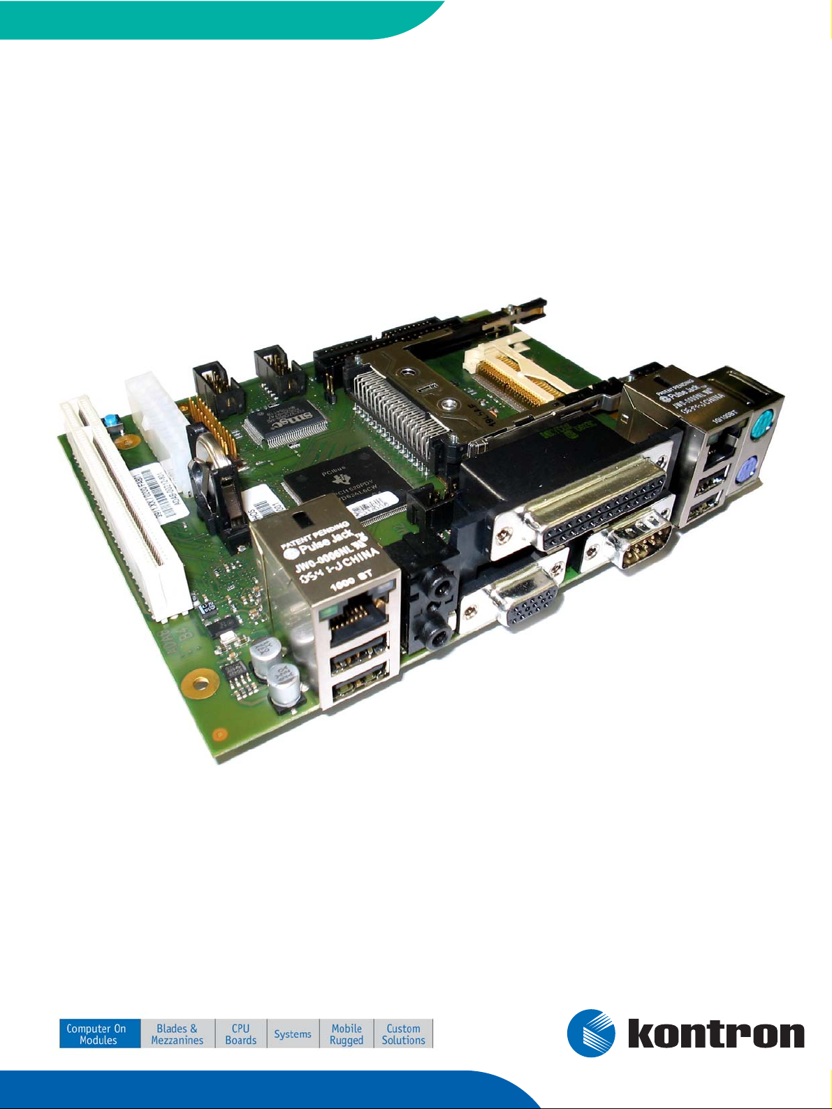
® ETX miniBaseboard
Document Revision 1.11
Page 2

This page intentionally left blank
Page 3

Table of Contents
Table of Contents
1 User Information........................................................................................................ 4
1.1 About This Document .........................................................................................4
1.2 Copyright Notice ...............................................................................................4
1.3 Trademarks ......................................................................................................4
1.4 Standards ........................................................................................................4
1.5 Warranty .........................................................................................................4
1.6 Technical Support..............................................................................................5
2 Specifications ............................................................................................................ 6
2.1 Mechanical Specifications ...................................................................................6
2.2 Environmental Specifications ..............................................................................7
2.2.1 Temperature.....................................................................................................7
2.2.2 Humidity .........................................................................................................7
3 Short description........................................................................................................ 8
4 Connector locations .................................................................................................... 9
5 Connector pin out ......................................................................................................10
5.1 Connector Overview .........................................................................................10
5.2 Feature Connector ...........................................................................................11
5.3 Flat panel Connector ........................................................................................ 12
6 Super I/O controller ...................................................................................................13
7 PCMCIA/CardBus Controller PCI1520 ............................................................................14
8 Dual Ethernet ...........................................................................................................15
8.1 Ethernet1 - ETX® Ethernet ................................................................................ 15
8.2 Ethernet2 - onboard Gigabit LAN ........................................................................15
9 Battery Information...................................................................................................16
10 Document History......................................................................................................17
Kontron User's Guide ETX miniBaseboard iii
Page 4

1 User Information
1 User Information
1.1 About This Document
This document provides information about products from Kontron Embedded Modules GmbH and/or its
subsidiaries. No warranty of suitability, purpose, or fitness is implied. While every attempt has been
made to ensure that the information in this document is accurate, the information contained within is
supplied “as-is” and is subject to change without notice.
For the circuits, descriptions and tables indicated, Kontron assumes no responsibility as far as patents or
other rights of third parties are concerned.
1.2 Copyright Notice
Copyright © 2007 Kontron Embedded Modules GmbH
All rights reserved. No part of this document may be reproduced, transmitted, transcribed, stored in a
retrieval system, or translated into any language or computer language, in any form or by any means
(electronic, mechanical, photocopying, recording, or otherwise), without the express written permission
of Kontron Embedded Modules GmbH.
DIMM-PC®, PISA®, ETX®, ETXexpress® , X-board®, DIMM-IO® and DIMM-BUS® are trademarks or
registered trademarks of Kontron Embedded Modules GmbH. Kontron is trademark or registered
trademark of Kontron AG.
1.3 Trademarks
The following lists the trademarks of components used in this board.
®
®
®
®
IBM, XT, AT, PS/2 and Personal System/2 are trademarks of International Business
Machines Corp.
Microsoft is a registered trademark of Microsoft Corp.
Intel is a registered trademark of Intel Corp.
All other products and trademarks mentioned in this manual are trademarks of their
respective owners.
1.4 Standards
Kontron Embedded Modules GmbH is certified to ISO 9000 standards.
1.5 Warranty
This Kontron Embedded Modules GmbH product is warranted against defects in material and
workmanship for the warranty period from the date of shipment. During the warranty period, Kontron
Embedded Modules GmbH will at its discretion decide to repair or replace defective products.
Within the warranty period, the repair of products is free of charge as long as warranty conditions are
observed.
Kontron User's Guide ETX miniBaseboard 4
Page 5
1 User Information
The warranty does not apply to defects resulting from improper or inadequate maintenance or handling
by the buyer, unauthorized modification or misuse, operation outside of the product’s environmental
specifications or improper installation or maintenance.
Kontron Embedded Modules GmbH will not be responsible for any defects or damages to other products
not supplied by Kontron Embedded Modules GmbH that are caused by a faulty Kontron Embedded
Modules GmbH product.
1.6 Technical Support
Technicians and engineers from Kontron Embedded Modules GmbH and/or its subsidiaries are available
for technical support. We are committed to making our product easy to use and will help you use our
products in your systems.
Before contacting Kontron Embedded Modules GmbH technical support, please consult our Web site at
http://www.kontron-emea.com/emd for the latest product documentation, utilities, and drivers. If the
information does not help solve the problem, contact us by telephone or email.
Asia Europe North/South America
Kontron Asia Inc. Kontron Embedded Modules GmbH Kontron America
4F, No.415, Ti-Ding Blvd., NeiHu
District,
Taipei 114, Taiwan
Tel: +886 2 2799 2789 Tel: +49 (0) 991-37024-0 Tel: +1 (888) 294 4558
Fax: + 886 2 2799 7399 Fax: +49 (0) 991-37024-333 Fax: +1 (858) 677 0898
mailto:sales@kontron.com.tw mailto:sales-kem@kontron.com mailto:sales@us-kontron.com
Brunnwiesenstr. 16
94469 Deggendorf – Germany
14118 Stowe Drive
Poway, CA 92064-7147
Kontron User's Guide ETX miniBaseboard 5
Page 6
2 Specifications
2 Specifications
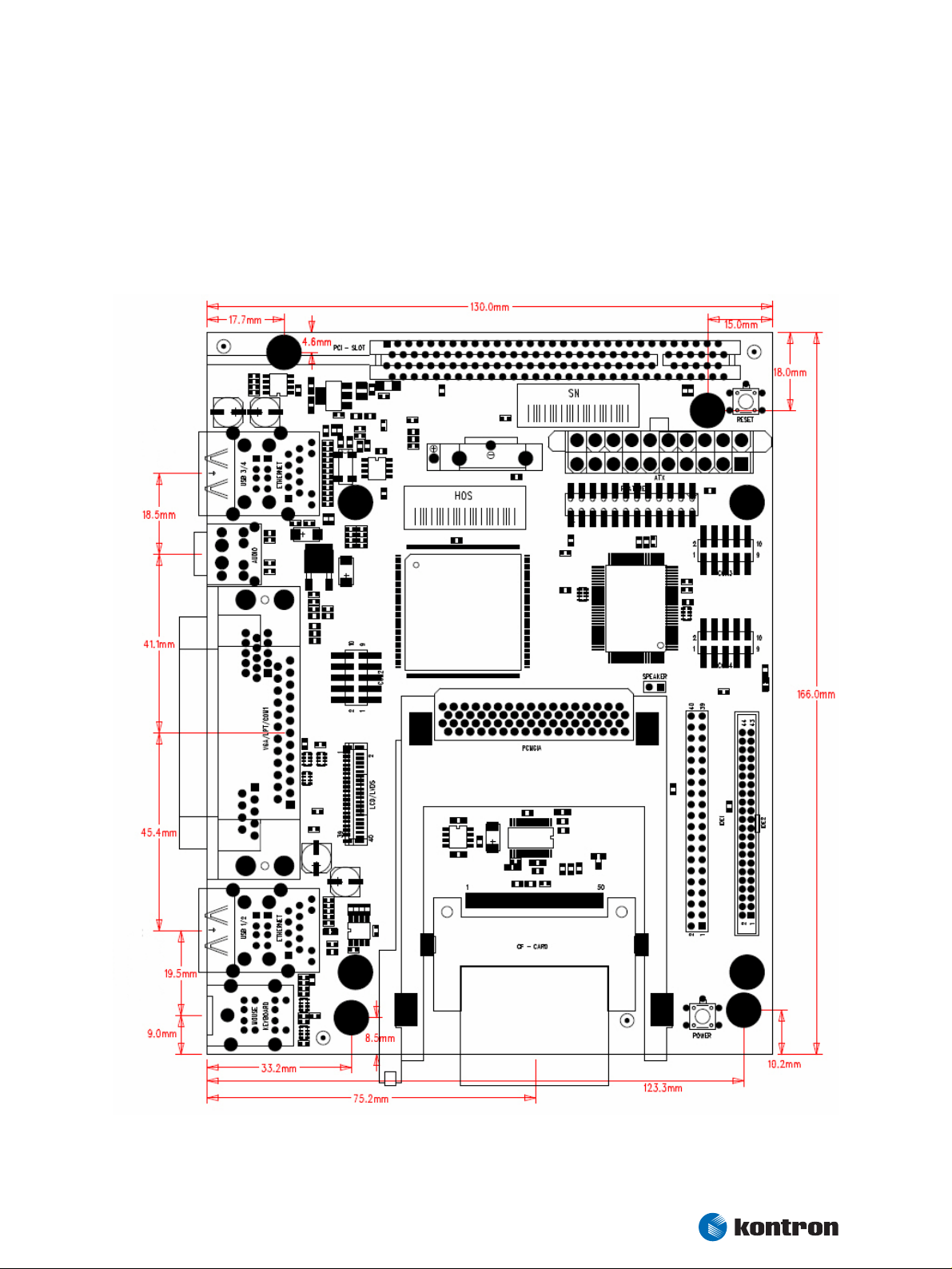
2.1 Mechanical Specifications
The ETX miniBaseboard is 166mm x 130mm in size and the height on top side of PCB is 29,5mm. See
more detailed mechanical specifications in the figure below:
Kontron User's Guide ETX miniBaseboard 6
Page 7

2.2 Environmental Specifications
2.2.1 Temperature
Operating:
2 Specifications
®
®
Ambient temperature: 0 to +70 °C
Non-operating: -30 to +85 °C
Storage:
®
Ambient temperature: -25 to +85 °C
Note: The maximum operating temperature is the maximum measurable temperature on any spot on a baseboards’
surface. You must maintain the temperature according to the above specification.
2.2.2 Humidity
®
®
Operating: 10% to 90% (non condensing)
Non operating: 5% to 95% (non condensing)
Kontron User's Guide ETX miniBaseboard 7
Page 8

3 Short description
3 Short description
The following short description is intended to convey a brief overall view of the components. Installation
alternatives are depicted herein. Only special non-standard PC functions are explained, as information
of all other interfaces is commonly available.
Summary of all available interfaces:
Connector Description
Feature connector Kontron 24pin standard connector for additional features
IDE1
IDE2 Secondary Master/Slave (2.00mm, 44pin connector)
LPT1 25 pol. SUB-D connector, combiconnector 2
COM1 9 pol. SUB-D (V.24), combiconnector 2
COM2 10 pol. 2.54 mm connector (V.24)
COM3 10 pol. 2.54 mm connector
COM4 10 pol. 2.54 mm connector
VGA 15pl. SUB-D, combiconnector 2
Flat panel interface JILI(D)-FFC-Connector (ETX board dependend)
USB1 Combiconnector 1
USB2 Combiconnector 1
USB3 Combiconnector 3
USB4 Combiconnector 3
Ethernet 1 10/100 Mbit, combiconnector 1
Ethernet 2 10/100/1000 Mbit, combiconnector 3
Primary Master (CF-Slot, e.g. as bootdevice)
Primary Slave (2.54mm, 40pin connector)
PS/2 PS/2 - Keyboard & Mouse
PCI Slot
PCMCIA/Cardbus Slot via external controller PCI1520
Audio Out 3.5mm jack
Audio In 3.5mm jack
Notes: * To protect external power lines of peripheral devices, make sure that:
- the wires have the right diameter to withstand the maximum available current
- the enclosure of the peripheral device fulfils the fire-protection requirements of IEC/EN60950
Kontron User's Guide ETX miniBaseboard 8
Page 9

4 Connector locations
4 Connector locations
Note: The ETX board is plugged on the bottom of the mini ETX Baseboard
Kontron User's Guide ETX miniBaseboard 9
Page 10

5 Connector pin out
5.1 Connector Overview
Pin# JILI (LVDS) JILI (digital) Feature COM 1,2,3,4
1 LTGIO0 VSYNC VCC_UL DCD
2 LCDDO0 R0 BATLOW# DSR
3 LCDDO1 R1 RSMRST# RX
4 DIGON DIGON SERIRQ# RTS
5 LCDDO2 R2 I2DAT TX
6 LCDDO3 R3 I2CLK CTS
7 BIASON HSYNC SMBCLK DTR
8 LCDDO4 R4 RKBCS# RI
9 LCDDO5 R5 KBINH GND
10 GND GND PWGIN -
11 LCDDO6 G0 PWRBTN# -
12 LCDDO7 G1 HLEDR -
13 GND GND GPE2# -
14 LCDDO8 G2 GPE1# -
15 LCDDO9 G3 EXTSMI -
16 JILI_DAT JILI_DAT GPCS# -
17 LCDDO10 G4 SMBALRT# -
18 LCDDO11 G5 SMBDAT -
19 JILI_CLK JILI_CLK EXT_PRG -
20 LCDDO12 B0 BATT -
21 LCDDO13 B1 GND -
22 DETECT# DETECT# GND -
23 LCDDO14 B2 GND -
24 LCDDO15 B3 Resistor 330Ω to VCC -
25 GND GND -
26 LCDDO16 B4 -
27 LCDDO17 B5 -
28 GND GND -
29 LCDDO18 SHFCLK -
30 LCDDO19 EN -
31 VCC VCC -
32 VCC VCC -
33 VCC VCC -
34 VCC VCC -
35 BLON# BLON# -
36 GND GND -
37 GND GND -
38 +12V +12V -
39 +12V +12V -
40 +12V +12V -
5 Connector pin out
Kontron User's Guide ETX miniBaseboard 10
Page 11

5 Connector pin out
The names of the COM ports are printed on the top of the PCB. Depending on the specific ETX module,
LVDS (JILI) or digital (JIDI) LCD signals are supported.
5.2 Feature Connector
Feature Connector
VCC_UL +5V UL-protected with inductor (600R@100MHz, 1A)
BATLOW# Battery low input. May be driven low by external circuitry to signal that the system battery is
low, or may be used to signal some other external power management event.
RSMRST# Resume Reset input. This input may be driven low by external circuitry in order to reset the
power management logic on the ETX module.
SERIRQ Serial interrupt request. This pin is used to support the serial interrupt protocol.
I2CLK, I2DAT Clock and data line of I2C-Bus. Switched I/O-lines with approximate 10kHz. Do not use as
multi master. Intended for I2C and other simple I/O-devices.
SMBDATA, SMBCLK Clock and data line of SM-Bus. For future use. Do not use today.
GPE2# General-purpose power management event input 2. May be driven low by external circuitry to
signal an external power management event. Within the ETX module, this pin is commonly
connected to the chipset’s RING# input.
GPE1# General-purpose power management event input 1. May be driven low by external circuitry to
signal an external power management event. Within the ETX module, this pin is commonly
connected to the chipset’s LID# input.
EXTSMI System management interrupt input. May be driven low by external circuitry to initiate an
SMI.
GPCS# Reserved. Do not connect to this pin.
SMBALRT# System Management Bus Alert input. May be driven low by SMB devices in order to signal an
event on the SM Bus.
EXT_PRG Reserved. Do not connect to this pin.
ROMKBCS# Reserved. Do not connect to this pin.
BATT 3V backup cell input. BATT should be connected to a 3V backup cell for RTC operation and
storage register non-volatility in the absence of system power. (VBATT = 2.4 – 3.3V)
KBINH Keyboard Inhibit.
PWGIN High active input for the ETX-PC indicates that power from the power supply is ready. It can
also be used as low active reset input signal.
PWRBTN# Power Button Input. This input is used to support the ACPI Power Button function.
HLEDR Low active output signal, which indicates activity on IDE interfaces.
Kontron User's Guide ETX miniBaseboard 11
Page 12

5 Connector pin out
5.3 Flat panel Connector
LCD Connector (JILI)
BIASON Controls panel contrast voltage.
DIGON Controls panel digital power.
BLON# Controls backlight power.
LTGIO0 General purpose I/O pin; not used by JILI interface.
JILI_DAT, JILI_CLK I2C interface for panel parameter EEPROM. This EEPROM is mounted on the LVDS receiver. The
data in the EEPROM allows the ETX module to automatically set the proper timing parameters
for a specific LCD panel.
DETECT# Panel hot-plug detection. Implementation of this pin is optional. See the specific ETX module
product manual for details.
LCDDO0..19 LCD data output pins LVDS support.
Pin Name LVDS signal Channel
LCDDO0 Txout0- first
LCDDO1 Txout0+ first
LCDDO2 Txout1- first
LCDDO3 Txout1+ first
LCDDO4 Txout2- first
LCDDO5 Txout2+ first
LCDDO6 Txclk- first
LCDDO7 Txclk+ first
LCDDO8 Txout3- first
LCDDO9 Txout3+ first
LCDDO10 Txout0- second
LCDDO11 Txout0+ second
LCDDO12 Txout1- second
LCDDO13 Txout1+ second
LCDDO14 Txout2- second
LCDDO15 Txout2+ second
LCDDO16 Txclk- second
LCDDO17 Txclk+ second
LCDDO18 Txout3- second
LCD Connector (JIDI)
R[0..5], G[0..5], B[0..5] Parallel digital signals for red, green and blue pixel data.
HSYNC Horizontal Sync: This output supplies the horizontal synchronization pulse for flat panels.
This signal is named LP (Line Pulse) in some flat panel literature.
VSYNC Vertical Sync: This output supplies the vertical synchronization pulse for flat panels. This
signal is named FLM (First Line Marker) in some flat panel literature.
DE Data enable signal. Usage depends on display type.
SHCLK Panel data clock signal.
Kontron User's Guide ETX miniBaseboard 12
Page 13

6 Super I/O controller
6 Super I/O controller
The support of this controller is integrated in all Kontron's ETX® BIOS revisions. On this baseboard this
controller supports the additional serial ports (COM3 and COM4). Please check the Application Note
‘Connecting an external SuperIO controller to ETX or PC104’ (former JAP0033) and the ETX eval
schematics, available on our web site, for design-in example.
Kontron User's Guide ETX miniBaseboard 13
Page 14

7 PCMCIA/CardBus Controller PCI1520
7 PCMCIA/CardBus Controller PCI1520
The onboard PCMCIA controller is configured for parallel interrupts. Please note that using all available
COM ports may reduce the amount of available resources for interrupts (IRQs 3,4,10,11 are routed)
and/or I/O area to establish proper function of plugged memory or I/O devices. This device is PCI device
slot 3.
Kontron User's Guide ETX miniBaseboard 14
Page 15

8 Dual Ethernet
8.1 Ethernet1 - ETX® Ethernet
Ethernet1 connector is placed in Combiconnector1 and connected to ETX® Module.
LAN LED activity on Combiconnector1:
8 Dual Ethernet
®
®
Activity LED green = RX/TX activity
Link LED yellow = Link up
LED D5 activity on ETX miniBaseboard:
®
®
Speed LED D5 off = 10Mbps
Speed LED D5 green = 100Mbps
8.2 Ethernet2 - onboard Gigabit LAN
Ethernet2 connector is placed in Combiconnector3 and connected to onboard Gigabit LAN Controller
Intel82541EI. Please take into consideration that you may need a special driver from Intel for this
controller. The driver can be found in the download section for ETX miniBaseboard on Kontron’s
Webpage. This device is PCI device slot 1.
LAN LED activity on Combiconnector3:
®
®
®
®
®
LED1 green = Link up
LED1 blinking = RX/TX activity
LED2 off = 10Mbps
LED2 yellow = 100Mbps
LED2 green = 1000Mbps
Kontron User's Guide ETX miniBaseboard 15
Page 16

9 Battery Information
9 Battery Information
English:
CAUTION: Danger of explosion if battery is incorrectly replaced. Replace only with the same or
equivalent type recommended by the manufacturer. Dispose of used batteries according to
the manufacturer's instructions.
Deutsch:
VORSICHT: Explosionsgefahr bei unsachgemäßem Austausch der Batterie. Ersatz nur durch denselben
oder einen vom Hersteller empfohlenen gleichwertigen Typ. Entsorgung gebrauchter
Batterien nach Angaben des Herstellers.
French:
ATTENTION: Risque d'explosion avec l'échange inadéquat de la batterie. Remplacement seulement par le
même ou un type équivalent recommandé par le producteur. L'évacuation des batteries
usagées conformément à des indications du fabricant.
Danish:
ADVARSEL: Lithiumbatteri – Eksplosionsfare ved fejlagtig Håndtering. Udskifting må kun ske med
batteri af samme fabrikant og type. Lever det brugte batteri tilbage til leverandren.
Finnish:
VAROITUS: Paristo voi rãjãhtãã, jos se on virheellisesti asennettu. Vaihda paristo
ainoastaanlaltevalmistajan suosittelmaan tyyppiln. Havita kaytetty paristo valmistajan
ohjeiden mukaisesti.
Spanish:
Precaución: Peligro de explosión si la batería se sustituye incorrectamente. Sustituya solamente por el
mismo o tipo equivalente recomendado por el fabricante. Disponga las baterías usadas según
las instrucciones del fabricante.
Note: The battery of this product is not considered to be accessible by the end user. Therefore the safety
instructions are only given in English, German, French, Danish, Finish and Spanish language.
If the battery of this product however is accessible by the end user, it is in the responsibility of the
Kontron customer to give the corresponding safety instructions in the required language(s).
Kontron User's Guide ETX miniBaseboard 16
Page 17

10 Document History
Rev. Date Edited by Changes
06.03.06 T. Limbrunner short description created, first release
1.10 03.04.07
1.11 03.07.07 GUL Updated Footer and header
PRO
Changed to new Kontron Style, Updated description and added features of
Redesign, new product photo, new connector description and chapter
specifications.
10 Document History
Kontron User's Guide ETX miniBaseboard 17
 Loading...