

Page 1
Kontron User's Guide
ETX®-LX
Document Revision 1.20
Page 2

This page intentionally left blank
Page 3

Table of Contents
Kontron User's Guide ETX®-LX
iii
Table of Contents
1 User Information ........................................................................................................ 7
1.1 About This Document ......................................................................................... 7
1.2 Copyright Notice ............................................................................................... 7
1.3 Trademarks ...................................................................................................... 7
1.4 Standards ........................................................................................................ 7
1.5 Warranty ......................................................................................................... 7
1.6 Technical Support .............................................................................................. 8
2 Introduction .............................................................................................................. 9
2.1 ETX®-LX .......................................................................................................... 9
2.2 ETX® Documentation ......................................................................................... 9
2.3 ETX® Benefits ................................................................................................... 9
3 Specifications ........................................................................................................... 11
3.1 Functional Specifications .................................................................................. 11
3.2 Mechanical Specifications ................................................................................. 13
3.2.1 Module dimensions .......................................................................................... 13
3.3 Memory ......................................................................................................... 13
3.4 Electrical Specifications .................................................................................... 13
3.4.1 Supply Voltage ................................................................................................ 13
3.4.2 Supply Voltage Ripple ...................................................................................... 13
3.4.3 Supply Current 5 V_SB ...................................................................................... 13
3.4.4 Supply Current ................................................................................................ 14
3.4.5 CMOS Battery Power Consumption ...................................................................... 14
3.5 Environmental Specifications ............................................................................ 15
3.5.1 Temperature ................................................................................................... 15
3.5.2 Humidity ....................................................................................................... 15
3.6 MTBF ............................................................................................................. 15
4 Connector X1 Subsystems ........................................................................................... 16
4.1 PCI Bus .......................................................................................................... 16
4.2 USB .............................................................................................................. 16
4.3 Audio ............................................................................................................ 16
4.4 Serial IRQ ...................................................................................................... 16
4.5 3.3V Power Supply for External Components ......................................................... 16
5 Connector X2 Subsystems ........................................................................................... 18
5.1 ISA Bus Slot ................................................................................................... 18
6 Connector X3 Subsystems ........................................................................................... 19
Page 4

Table of Contents
Kontron User's Guide ETX®-LX
iv
6.1 VGA Output .................................................................................................... 19
6.2 LVDS Flat Panel Interface (JILI) .......................................................................... 20
6.3 Digital Flat Panel Interface (JIDI) ....................................................................... 20
6.4 Serial Ports (1 and 2) ....................................................................................... 20
6.5 PS/2 Keyboard ................................................................................................ 20
6.6 PS/2 Mouse .................................................................................................... 20
6.7 IrDA .............................................................................................................. 21
6.8 Parallel Port ................................................................................................... 21
6.9 Floppy ........................................................................................................... 21
7 Connector X4 Subsystems ........................................................................................... 22
7.1 IDE Ports ....................................................................................................... 22
7.2 Ethernet ........................................................................................................ 22
7.3 Power Control ................................................................................................. 22
7.3.1 Power Good / Reset Input ................................................................................. 22
7.4 Power Management ......................................................................................... 22
7.4.1 ATX PS Control ................................................................................................ 22
7.5 Miscellaneous Circuits ...................................................................................... 23
7.5.1 Speaker ......................................................................................................... 23
7.5.2 Battery .......................................................................................................... 23
7.5.3 I2C Bus .......................................................................................................... 23
7.5.4 SM Bus .......................................................................................................... 23
8 Special Features ........................................................................................................ 24
8.1 Watchdog Timer .............................................................................................. 24
8.2 SATA ............................................................................................................. 25
9 Design Considerations ................................................................................................ 26
9.1 Thermal Management ....................................................................................... 26
9.2 Module Dimensions ......................................................................................... 27
Appendix A: block diagram ........................................................................................... 28
10 Appendix B: System Resources .................................................................................... 29
10.1 Interrupt Request (IRQ) Lines ............................................................................ 29
10.2 Direct Memory Access (DMA) Channels ................................................................. 29
10.3 Memory Area .................................................................................................. 30
10.4 I/O Address Map ............................................................................................. 30
10.5 Peripheral Component Interconnect (PCI) Devices ................................................. 31
10.6 Inter-IC (I2C) Bus ............................................................................................ 31
10.7 System Management (SM) Bus ........................................................................... 31
10.8 JILI-I2C Bus .................................................................................................... 31
11 Appendix C: BIOS Operation ........................................................................................ 32
Page 5

Table of Contents
Kontron User's Guide ETX®-LX
v
11.1 Overview........................................................................................................ 32
11.2 Determining the BIOS Version ............................................................................ 32
11.3 Setup Guide ................................................................................................... 32
11.3.1 Starting the BIOS Setup Utility ........................................................................... 32
11.4 Main Menu ..................................................................................................... 32
11.4.1 Setup Items ................................................................................................... 33
11.5 Standard CMOS Features ................................................................................... 35
11.5.1 Primary Master and Slave Submenu ..................................................................... 36
11.6 Advanced BIOS Features ................................................................................... 37
11.7 Advanced Chipset Features ................................................................................ 39
11.8 Integrated Peripherals ..................................................................................... 41
11.9 Power Management Setup ................................................................................. 44
11.9.1 IRQ Wakeup Events .......................................................................................... 45
11.10 PnP/PCI Configurations .................................................................................... 46
11.11 PC Health Status ............................................................................................. 47
11.12 Load Fail-Safe Defaults ..................................................................................... 47
11.13 Load Optimized Defaults ................................................................................... 47
11.14 Supervisor/User Password Setting ...................................................................... 47
11.15 Exit Selection ................................................................................................. 48
12 Appendix D: ETX® Connector Pinouts ............................................................................ 49
12.1 Connector Locations ........................................................................................ 49
12.2 Signal Description ........................................................................................... 50
12.3 Connector X1 (PCI Bus, USB, Audio) .................................................................... 50
12.3.1 Connector X1 (Signal Levels) ............................................................................. 51
12.4 Connector X2 (ISA Bus) .................................................................................... 53
12.4.1 Connector X2 (Signal Levels) ............................................................................. 54
12.5 Connector X3 (VGA, LVDS, TTL, COM1 and COM2, LPT/Floppy, Mouse, Keyboard) ........... 56
12.5.1 Flat-Panel Interfaces ........................................................................................ 56
12.5.2 Parallel Port / Floppy Interfaces ......................................................................... 57
12.5.3 Connector X3 (Signal Levels) ............................................................................. 58
12.6 Connector X4 (IDE 1, IDE 2, Ethernet, Miscellaneous) ............................................. 60
12.6.1 Connector X4 (Signal Levels) ............................................................................. 61
12.7 Serial ATA connectors ....................................................................................... 63
12.8 Compact Flash Socket ....................................................................................... 64
12.8.1 Compact Flash Socket pinout ............................................................................. 64
13 Appendix F: Limitations ............................................................................................. 65
13.1 BIOS Limitations ............................................................................................. 65
13.2 Limitations of hardware revision CE B.3.x (18027-0000-
50-0 / 18027-0000-50-1) ................................................................................. 65
13.3 Limitations of hardware revision CE 2.x.x/3.x.x/4.x.x (180027-
0000-50-4 / 18027-0000-50-5) ......................................................................... 65
Page 6

Table of Contents
Kontron User's Guide ETX®-LX
vi
13.4 Workaround for drop in supply voltage in AT/single supply mode .............................. 66
14 Appendix E: JIDA Standard .......................................................................................... 67
14.1 JIDA Information ............................................................................................ 67
15 Appendix F: PC Architecture Information ...................................................................... 68
15.1 Buses ............................................................................................................ 68
15.1.1 ISA, Standard PS/2 – Connectors ........................................................................ 68
15.1.2 PCI/104 ......................................................................................................... 68
15.2 General PC Architecture .................................................................................... 68
15.3 Ports ............................................................................................................. 69
15.3.1 RS-232 Serial ................................................................................................. 69
15.3.2 Serial ATA ...................................................................................................... 69
15.3.3 USB .............................................................................................................. 69
15.4 Programming ................................................................................................. 69
16 Appendix G: Document-Revision History ....................................................................... 71
Page 7

1 User Information
Kontron User's Guide ETX®-LX
7
1 User Information
1.1 About This Document
This document provides information about products from Kontron Embedded Modules GmbH and/or its
subsidiaries. No warranty of suitability, purpose, or fitness is implied. While every attempt has been
made to ensure that the information in this document is accurate, the information contained within is
supplied ―as-is‖ and is subject to change without notice.
For the circuits, descriptions and tables indicated, Kontron assumes no responsibility as far as patents or
other rights of third parties are concerned.
1.2 Copyright Notice
Copyright © 2003-2007 Kontron Embedded Modules GmbH
All rights reserved. No part of this document may be reproduced, transmitted, transcribed, stored in a
retrieval system, or translated into any language or computer language, in any form or by any means
(electronic, mechanical, photocopying, recording, or otherwise), without the express written permission
of Kontron Embedded Modules GmbH.
DIMM-PC®, PISA®, ETX®, ETXexpress®, microETXexpress™, X-board®, DIMM-IO® and DIMM-BUS® are
trademarks or registered trademarks of Kontron Embedded Modules GmbH. Kontron is trademark or
registered trademark of Kontron AG.
1.3 Trademarks
The following lists the trademarks of components used in this board.
IBM, XT, AT, PS/2 and Personal System/2 are trademarks of International Business
Machines Corp.
Microsoft is a registered trademark of Microsoft Corp.
Intel is a registered trademark of Intel Corp.
All other products and trademarks mentioned in this manual are trademarks of their
respective owners.
1.4 Standards
Kontron Embedded Modules GmbH is certified to ISO 9000 standards.
1.5 Warranty
This Kontron Embedded Modules GmbH product is warranted against defects in material and
workmanship for the warranty period from the date of shipment. During the warranty period, Kontron
Embedded Modules GmbH will at its discretion decide to repair or replace defective products.
Within the warranty period, the repair of products is free of charge as long as warranty conditions are
observed.
Page 8
1 User Information
Kontron User's Guide ETX®-LX
8
The warranty does not apply to defects resulting from improper or inadequate maintenance or handling
Asia
Europe
North/South America
Kontron Asia Inc.
Kontron Embedded Modules GmbH
Kontron America
4F, No.415, Ti-Ding Blvd., NeiHu
District,
Taipei 114, Taiwan
Brunnwiesenstr. 16
94469 Deggendorf – Germany
14118 Stowe Drive
Poway, CA 92064-7147
Tel: +886 2 2799 2789
Tel: +49 (0) 991-37024-0
Tel: +1 (888) 294 4558
Fax: + 886 2 2799 7399
Fax: +49 (0) 991-37024-333
Fax: +1 (858) 677 0898
mailto:sales@kontron.com.tw
mailto:sales-kem@kontron.com
mailto:sales@us-kontron.com
by the buyer, unauthorized modification or misuse, operation outside of the product‘s environmental
specifications or improper installation or maintenance.
Kontron Embedded Modules GmbH will not be responsible for any defects or damages to other products
not supplied by Kontron Embedded Modules GmbH that are caused by a faulty Kontron Embedded
Modules GmbH product.
1.6 Technical Support
Technicians and engineers from Kontron Embedded Modules GmbH and/or its subsidiaries are available
for technical support. We are committed to making our product easy to use and will help you use our
products in your systems.
Before contacting Kontron Embedded Modules GmbH technical support, please consult our Web site at
http://www.kontron-emea.com/emd for the latest product documentation, utilities, and drivers. If the
information does not help solve the problem, contact us by telephone or email.
Page 9

2 Introduction
Kontron User's Guide ETX®-LX
9
2 Introduction
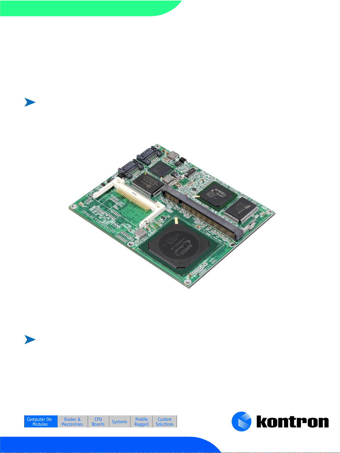
2.1 ETX®-LX
The ETX®-LX is an ETX® (Embedded Technology eXtended) form factor computer-on-module combining
the extremely low power consumption and high performance of the AMD Geode™ LX 800 Processor with
integrated Northbridge and the AMD CS5536 Companion Device. The LX 800 features a 128KB L2 Cache
and supports DDR400 SODIMM up to 1024 MB.
The ETX®-LX is fully compliant with the ETX® Component SBC™ Specification V3.0. This computer-on-
module features a 32-bit/33MHz PCI Bus Interface, IDE, serial ports, parallel port, Ethernet, Compact
Flash, USB v2.0, LVDS panel support, keyboard/mouse and AC‘97 audio. The flexibility of the ETX®
computer-on-module concept allows the baseboard designer to optimize how each of these functions is
physically implemented.
2.2 ETX® Documentation
This product manual serves as one of three principal references for an ETX® design. It documents the
specifications and features of ETX®-LX modules. The other two references, which are available from the
Kontron Web site, include:
The ETX® Specification defines the ETX® module form factor, pin out, and signals. You should read this
first.
The ETX® Design Guide serves as a general guide for baseboard design, with a focus on maximum
flexibility to accommodate a range of ETX® modules.
2.3 ETX® Benefits
Embedded technology extended (ETX®) modules are very compact (~100mm square, 12mm thick),
highly integrated computers. All ETX® modules feature a standardized form factor and a standardized
connector layout that carry a specified set of signals. This standardization allows designers to create a
single-system baseboard that can accept present and future ETX® modules.
ETX® modules include common personal computer (PC) peripheral functions such as:
Graphics
Parallel, Serial, and USB ports
Keyboard/mouse
Ethernet
Sound
IDE
The baseboard designer can optimize exactly how each of these functions implements physically.
Designers can place connectors precisely where needed for the application on a baseboard designed to
optimally fit a system‘s packaging.
Page 10

2 Introduction
Kontron User's Guide ETX®-LX
10
Peripheral PCI or ISA buses can be implemented directly on the baseboard rather than on mechanically
unwieldy expansion cards. The ability to build a system on a single baseboard using the computer as one
plug-in component simplifies packaging, eliminates cabling, and significantly reduces system-level cost.
A single baseboard design can use a range of ETX® modules. This flexibility can differentiate products at
various price/performance points, or to design future proof systems that have a built-in upgrade path.
The modularity of an ETX® solution also ensures against obsolescence as computer technology evolves.
A properly designed ETX® baseboard can work with several successive generations of ETX® modules.
An ETX® baseboard design has many advantages of a custom, computer-board design but delivers better
obsolescence protection, greatly reduced engineering effort, and faster time to market.
Page 11

3 Specifications
Kontron User's Guide ETX®-LX
11
3 Specifications
3.1 Functional Specifications
Processor & Northbridge: AMD Geode™ LX 800 @ 500MHz
AMD Geode™ LX 800 CPU, operates from 200MHz up to 500MHz
Cache: 64KB-I /64KB-D Cache, 128KB L2 Cache
MMX and 3DNow
GeodeLink™ Control Processor, Interface Units, Memory Controller, PCI Bridge
PCI 2.2 compliant 33 MHz operation
Memory: One unbuffered DDR 266/333/400 DDR SODIMM up to 1024MB
PCI Bus: 32-bit/33MHz 4 PCI Masters (3,3V only)
Onboard video graphics array (VGA): Integrated in LX 800
CRT: 1920x1440x8bpp at 60Hz, 1600x1200x16bpp at 72Hz
One channel LVDS 87.5MHz with LVDS Transmitter NS DS90C385A
LVDS: 1x24bpp (open LDI) or 1x18bpp
TFT Resolution up to 1024x768 with LVDS variant and 1600x1200 with TTL variant
Real-Time Clock (RTC) with CMOS RAM
Power Management Controller — ACPI v2.0 compliant
Southbridge: AMD CS5536 Companion Device
Primary IDE: 1 Channel UDMA-66/100 IDE port
Universal Serial Bus (USB): 4x USB 2.0
USB 1.1 supported by one OHCI-based host controller
USB 2.0 supported by one EHCI-based host controller
Audio Codec ‗97 (AC‘97) Controller
System Management Bus (SMB) Controller
LPC Bus
Watchdog Timer (WDT)
ISA Bus: Fintek LPC to ISA Bridge F85226FG
Supports only 8/2x8 bit memory, I/O, IRQ slave feature
PCI to SATA Controller: VIA VT6421A
2 Channels Serial ATA Spec. Rev. 1.0, up to 150 MB/s per channel
Secondary IDE: 1 Channel UDMA-66/100/133 IDE port
Onboard Compact Flash socket (Master on secondary IDE)
Page 12

3 Specifications
Kontron User's Guide ETX®-LX
12
Super I/O: Winbond W83627HF LPC Super I/O
Serial Ports (COM1 and COM2)
Two high-speed 16550 compatible UARTs with 16-byte send/receive FIFOs
Transistor-to-transistor (TTL) signals only
Infrared Device Association (IrDA) 1.0 SIR interface
Parallel Port (LPT1) - Shared with floppy signals: Enhanced Parallel Port (EPP) and
Extended Capabilities Port (ECP) with bi-directional capability
Floppy - shared with LPT signals: 360K/720K/1.2M/1.44M/2.88M format; 250K,
300K, 500K, 1M, 2M bps data transfer rate
IrDA version 1.0 SIR protocol
PS/2 Keyboard and Mouse
Onboard Ethernet: Intel® 82551ER
10BASE-T/100BASE-T LAN
Audio: Realtek ALC203
16-bit, full-duplex AC'97 Rev. 2.3 compatible audio CODEC
BIOS: Award, 512KB Flash BIOS
BIOS support for external super I/O (COM3, COM4, LPT, and Floppy)
Page 13

3 Specifications
Kontron User's Guide ETX®-LX
13
3.2 Mechanical Specifications
3.2.1 Module dimensions
95.0 mm x 114.0 mm (3.75‖ x 4.5‖)
Height approx. 10 mm (0.4‖)
3.3 Memory
The maximum recommended height of a memory module is 2.8mm. SO-DIMM DDR
memory modules not following this specification may cause mounting problems and
contact the heatspreader and/or the LPCtoISA Bridge
Recommended memory:
256MB: Part No. 97007-2560-00-0MLX
512MB: Part No. 97007-5120-00-0MLX
1024MB: Part No. 97007-1024-00-0MLX
3.4 Electrical Specifications
3.4.1 Supply Voltage
5V DC +/- 5%
3.4.2 Supply Voltage Ripple
Maximum 100 mV peak to peak 0 – 20 MHz
3.4.3 Supply Current 5 V_SB
Typical 100 mA, peak 250 mA
Page 14
3 Specifications
Kontron User's Guide ETX®-LX
14
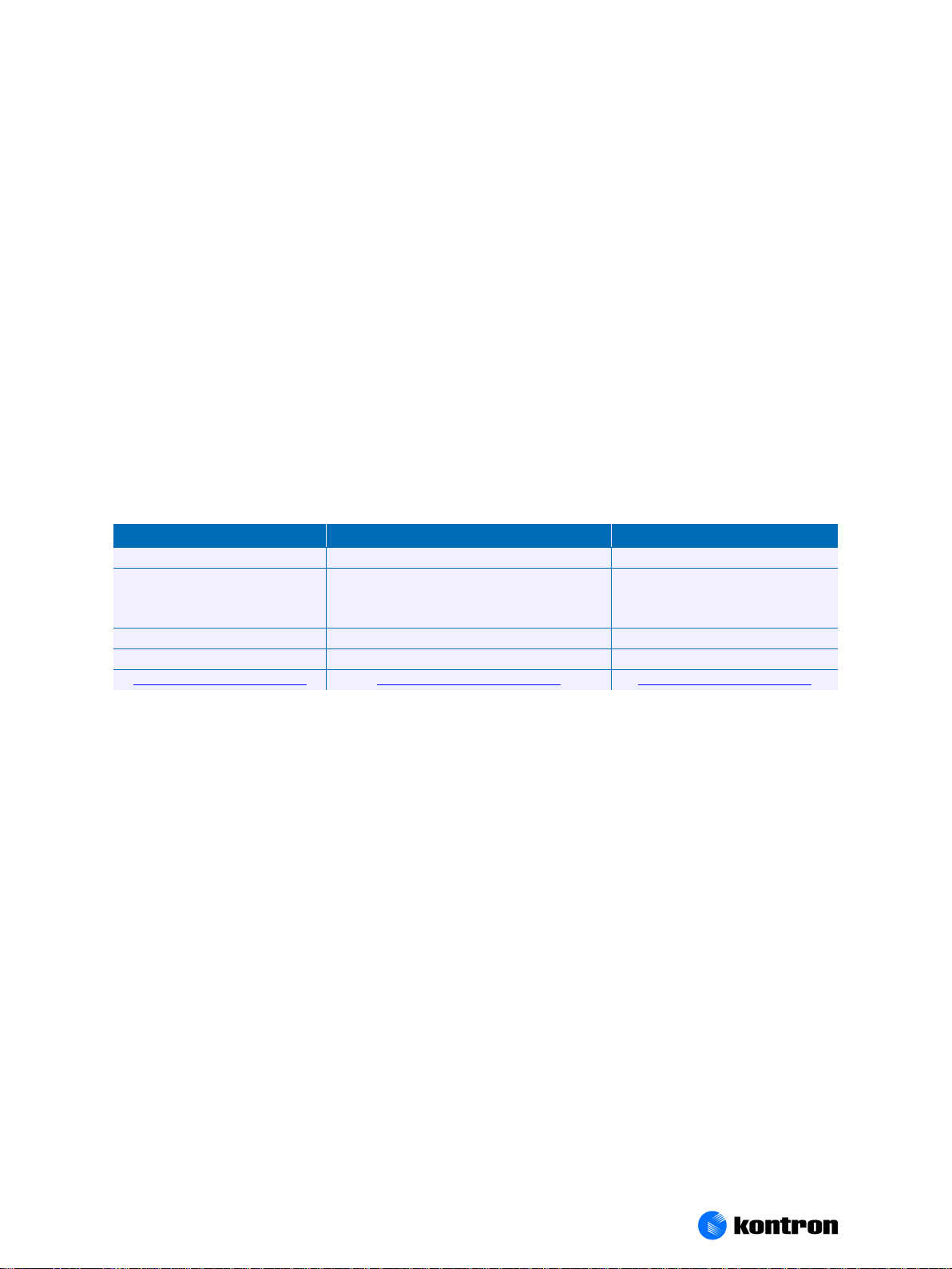
3.4.4 Supply Current
CPU Clock
500MHz
Mode
Prompt
Standby
Suspend
Power
Consumption
1.48 A
7,38 W
1,28 A
6,43 W
1,28 A
6,43 W
CPU Clock
500MHz
Mode
Full Load
Idle
Standby S1
Standby S3
Power
Consumption
1.52 A
7,58 W
1,26 A
6,50 W
0,96 A
5,00 W
0,35 W
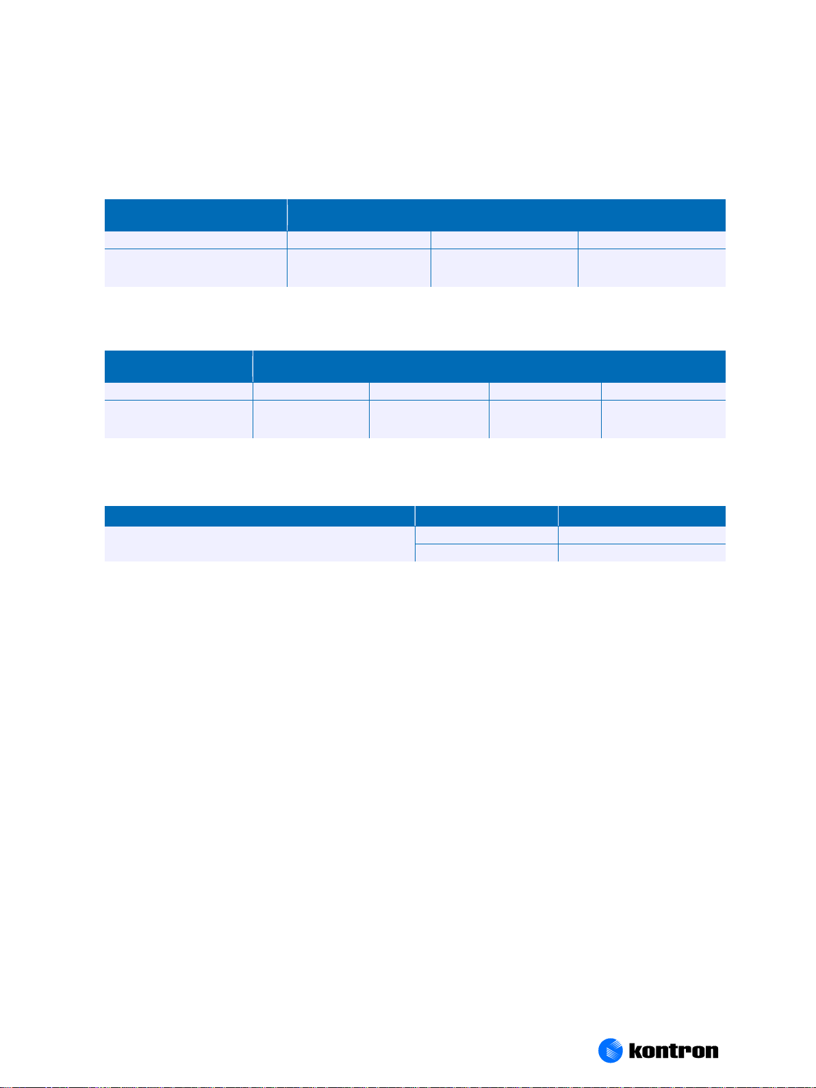
RTC
Voltage
Current
Winbond W83627HF
2.5V
1.6 µA
3.0V
2.7 µA
Power-consumption tests were executed under DOS and WindowsXP with 512MB of RAM.
DOS:
Windows XP:
3.4.5 CMOS Battery Power Consumption
CMOS battery power consumption was measured with an ETX®-LX module on a standard Kontron ETX®
evaluation board. The system was turned off and the battery was removed from the evaluation board.
The 2.5 V or 3.0 V of power was supplied from a DC power supply. Do not use these values to calculate the
CMOS battery lifetime.
Page 15

3 Specifications
Kontron User's Guide ETX®-LX
15
3.5 Environmental Specifications
3.5.1 Temperature
Operating: (with Kontron Embedded Modules GmbH heat-spreader plate assembly):
Ambient temperature: 0 to +60 C
Maximum Heatspreader-plate temperature: 0 to +60 C (*)
Non-operating: -30 to +85 C
See the Thermal Management chapter for additional information.
Note: *The maximum operating temperature with the Heatspreader plate is the maximum measurable temperature
on any spot on the Heatspreader’s surface. You must maintain the temperature according to the above
specification.
3.5.2 Humidity
Operating: 10% to 90% (non condensing)
Non operating: 5% to 95% (non condensing)
3.6 MTBF
The following MTBF (Mean Time between Failure) values were calculated using a combination of
manufacturer‘s test data, if the data was available, and a Bellcore calculation for the remaining parts.
The Bellcore calculation used is ―Method 1 Case 1‖. In that particular method the components are
assumed to be operating at a 50 % stress level in a 40° C ambient environment and the system is
assumed to have not been burned in. Manufacturer‘s data has been used wherever possible. The
manufacturer‘s data, when used, is specified at 50° C, so in that sense the following results are slightly
conservative. The MTBF values shown below are for a 40° C in an office or telecommunications
environment. Higher temperatures and other environmental stresses (extreme altitude, vibration, salt
water exposure, etc.) lower MTBF values.
System MTBF (hours): 142148
Notes: Fans usually shipped with Kontron Embedded Modules GmbH products have 50,000-hour typical operating
life. The above estimates assume no fan, but a passive heat sinking arrangement.
Estimated RTC battery life (as opposed to battery failures) is not accounted for in the above figures and need
to be considered for separately. Battery life depends on both temperature and operating conditions. When
the Kontron unit has external power; the only battery drain is from leakage paths.
Page 16

4 Connector X1 Subsystems
Kontron User's Guide ETX®-LX
16
4 Connector X1 Subsystems
4.1 PCI Bus
The implementation of this subsystem complies with the ETX® Specification. Implementation
information is provided in the ETX® Design Guide. Refer to the documentation for additional
information.
4.2 USB
One OHCI and EHCI USB host controller each supporting both version 1.1 and 2.0 USB standards are on
the Geode™ CS5536 Companion Device. A total of 4 USB ports are provided.
Configuration
The USB controllers are PCI bus devices. The BIOS allocates required system resources during
configuration of the PCI bus.
4.3 Audio
The sound function on the ETX®-LX board comes from an AC‘97 controller integrated in the Geode™
CS5536 Companion Device and a Realtek ALC203 AC‘97 Codec. The 20-bit DAC, 18-bit ADC, AC'97 2.3
compatible, full-duplex codec supports a Line In, a Stereo Line Out, and a Mono Microphone In
interface.
Configuration
The audio controller is a PCI bus device. The BIOS allocates required system resources during
configuration of the PCI device.
4.4 Serial IRQ
The serial IRQ pin offers a standardized interface to link interrupt request lines to a single wire.
Configuration
The serial IRQ machine is in ―Quiet Mode‖, the frame size is 21 frames and the start frame pulse width is
4 clocks.
4.5 3.3V Power Supply for External Components
The ETX®-LX offers the ability to connect external 3.3V devices to the onboard-generated supply voltage.
Pin 12 and Pin 16 of Connector X1 are used to connect to the +3.3V ±5% power supply. The maximum
external load is 500mA. Contact Kontron Embedded Systems Technical Support for help with this
feature.
Warning: Do not connect 3.3 V pins to an external 3.3 V supply!
Page 17

4 Connector X1 Subsystems
Kontron User's Guide ETX®-LX
17
For additional information, refer to the ETX® Design Guide, I2C application notes, and JIDA
specifications, all of which are available on the Kontron Embedded Systems Web site.
Page 18

5 Connector X2 Subsystems
Kontron User's Guide ETX®-LX
18
5 Connector X2 Subsystems
5.1 ISA Bus Slot
The implementation of this subsystem complies with the ETX® Specification. Implementation
information is provided in the ETX® Design Guide. Refer to the documentation for additional
information.
LPC type, only supports 8/2x8 bit memory, I/O, IRQ slave feature
Page 19

6 Connector X3 Subsystems
Kontron User's Guide ETX®-LX
19
6 Connector X3 Subsystems
6.1 VGA Output
The ETX®-LX graphics subsystem is integrated in the AMD Geode™ LX 800 CPU/Northbridge.
Graphics Processor
Command buffer interface
Hardware accelerated rotation BLTs
Colour depth conversion
Palletized colour
Full 8x8 colour pattem buffer
Separate base addresses for all channels
Monochrome inversion
Display Controller
Retrieves graphics, video, and cursor data.
Serializes the streams.
Performs any necessary colour lookups and output for matting.
Interface to the Video Processor for driving the display device(s).
CRT resolution: 1920x1440x8bbp@60Hz, 1600x1200x16bbp@100Hz
Supports up to 1600*1200*32bbp@60Hz TTL and 1027*768*32bbp@60Hz LVDS
Video Processor
Supports video scaling, mixing and VOP
Hardware video up/down scalar
Graphics/video alpha blending and colour key muxing
Digital VOP (SD and HD) or TFT outputs
Legacy RGB mode
VOP supports SD and HD 480p, 480i, 720p, and 1080i
VESA 1.1, 2.0 and BT.601 24-bit (out only), BT.656 compliant
Integrated Analog CRT DAC, System Clock PLLs and Dot Clock PLL
Configuration
The graphics controller requires the following resources:
An IRQ
Several I/O addresses
Page 20

6 Connector X3 Subsystems
Kontron User's Guide ETX®-LX
20
Memory-address blocks in high memory
The BIOS allocates the resources during AGP configuration. Many resources are set for compatibility with
industry-standard settings.
6.2 LVDS Flat Panel Interface (JILI)
The user interface for flat panels is the JUMPtec Intelligent LVDS Interface (JILI). The implementation of
this subsystem complies with the ETX® Specification. Implementation information is provided in the
ETX® Design Guide. Refer to the documentation for additional information.
6.3 Digital Flat Panel Interface (JIDI)
The ETX®-LX does support the JUMPtec Intelligent Digital Interface (JIDI) optional.
6.4 Serial Ports (1 and 2)
The ETX®-LX supports two serial interfaces (TTL). You can use COM2 for IrDA SIR Operation. This feature is
implemented in the super I/O device, which is a Winbond 83627HF.
The implementation of the serial interface complies with the ETX® Specification. Implementation
information is provided in the ETX® Design Guide. Refer to the documentation for additional
information.
Configuration
The serial-communication interface uses I/O and IRQ resources. The resources are allocated by the BIOS
during POST configuration and are set to be compatible with common PC/AT settings. Use the BIOS setup
to change some parameters that relate to the serial-communication interface.
6.5 PS/2 Keyboard
The implementation of the keyboard interface complies with the ETX® Specification. Implementation
information is provided in the ETX® Design Guide. Refer to the documentation for additional
information.
Configuration
The keyboard uses I/O and IRQ resources. The BIOS allocates the resources during POST configuration.
The resources are set to be compatible with common PC/AT settings. Use the BIOS setup to change some
keyboard-related parameters.
6.6 PS/2 Mouse
The implementation of the mouse interface complies with the ETX® Specification. Implementation
information is provided in the ETX® Design Guide. Refer to the documentation for additional
information.
Page 21

6 Connector X3 Subsystems
Kontron User's Guide ETX®-LX
21
Configuration
The mouse uses I/O and IRQ resources. The BIOS allocates the resources during POST configuration. The
resources are set to be compatible with common PC/AT settings. You can change some mouse-related
parameters from the BIOS setup.
6.7 IrDA
The ETX®-LX is capable of IrDA SIR operation. This feature is implemented in the Winbond 83627HF.
Contact Kontron Embedded Systems for help with this feature.
6.8 Parallel Port
The parallel-communication interface shares signals with the floppy-disk interface. The implementation
of this parallel port complies with the ETX® Specification. Implementation information is provided in the
ETX® Design Guide. Refer to the documentation for additional information.
Configuration
The parallel-communication interface uses I/O, IRQ, and DMA resources. The resources are allocated by
the BIOS during POST configuration and are set to be compatible with common PC/AT settings. You can
change some parameters of the parallel-communication interface through the BIOS setup.
6.9 Floppy
The floppy-disk interface shares signals with the parallel-communication interface. The floppy interface
is limited to one drive (drive_1). A standard floppy cable has two connectors for floppy drives. One
connector has a non-twisted cable leading to it, the other has a twisted cable leading to it. When using
the floppy interface you must connect the floppy drive to the connector (drive_1) that has the nontwisted cable leading to it.
The implementation of this subsystem complies with the ETX® Specification. Implementation
information is provided in the ETX® Design Guide. Refer to the documentation for additional
information.
Configuration
The floppy-disk controller uses I/O, IRQ, and direct memory access (DMA) resources. These resources are
allocated by BIOS during POST configuration and are compatible with common PC/AT settings. You can
change some parameters of the parallel-communication interface through the BIOS setup.
Page 22

7 Connector X4 Subsystems
Kontron User's Guide ETX®-LX
22
7 Connector X4 Subsystems
7.1 IDE Ports
The Primary IDE host adapter is capable of UDMA/100 operation. The implementation of this subsystem
complies with the ETX® Specification. Implementation information is provided in the ETX® Design Guide.
Refer to those documents for additional information.
A Compact Flash socket (Secondary Master) for commercial Compact Flash modules and a Secondary IDE
Channel is integrated on the module via VT6421A SATA Controller.
Configuration
Primary and secondary IDE host adapters are PCI bus devices. They are configured by the BIOS during PCI
device configuration. You can disable them in setup. Resources used by the primary and secondary IDE
host adapters are compatible with the PC/AT.
7.2 Ethernet
The Ethernet interface is based on the Intel® 82551ER Fast Ethernet PCI controller. This 32-bit PCI
controller is a fully integrated 10/100BASE-TX LAN solution.
The Ethernet interface requires an external transformer. See the ETX® Design Guide for suggestions on
transformer selection.
Configuration
The ETX®-LX provides Ethernet connectivity using the Intel® 82551ER Integrated
10BASE-T/100BASE-TX Ethernet Controller.
Note: Implementation and limitation information is provided in the ETX® Design Guide from document revision
2.1. Refer to the documentation for additional information.
7.3 Power Control
7.3.1 Power Good / Reset Input
The ETX®-LX provides an external input for a power-good signal or a manual- reset pushbutton. The
implementation of this subsystem complies with the ETX® Specification. Implementation information is
provided in the ETX® Design Guide. Refer to the documentation for additional information.
7.4 Power Management
7.4.1 ATX PS Control
The ETX®-LX can control the main power output of an ATX-style power supply. The implementation of this
subsystem complies with the ETX® Specification. Implementation information is provided in the ETX®
Design Guide. Refer to the documentation for additional information.
Page 23

7 Connector X4 Subsystems
Kontron User's Guide ETX®-LX
23
7.5 Miscellaneous Circuits
7.5.1 Speaker
The implementation of the speaker output complies with the ETX® Specification. Implementation
information is provided in the ETX® Design Guide. Refer to the documentation for additional
information.
7.5.2 Battery
The implementation of the battery input complies with the ETX® Specification. Implementation
information is provided in the ETX® Design Guide. Refer to the documentation for additional
information.
In compliance with EN60950, there are at least two current-limiting devices (resistor and diode)
between the battery and the consuming component.
7.5.3 I
The ETX®-LX provides a software-driven I2C port to communicate with external I2C slave devices. This port
is implemented on ETX® Pins I2DAT and I2CLK.
You also can access the I2C Bus via JUMPtec‘s Intelligent Device Architecture (JIDA) BIOS functions.
For additional information, refer to the ETX® Design Guide. I2C application notes and JIDA specifications
are available at the Kontron Web site.
2
C Bus
7.5.4 SM Bus
System Management (SM) bus signals are connected to the SM bus controller, which is located in the
AMD Geode CS5536 Companion Device. For more information about the SM bus, please see the System
Management (SM) Bus section in the Appendix B: System Resources chapter.
Page 24

8 Special Features
Kontron User's Guide ETX®-LX
24
8 Special Features
8.1 Watchdog Timer
This feature is implemented in the AMD Geode CS5536 Companion Device. You can configure the
Watchdog Timer (WDT) from the BIOS setup to start after a set amount of time after power-on boot. The
application software should strobe the WDT to prevent its timeout. Upon timeout, the WDT resets and
restarts the system. This provides a way to recover from program crashes or lockups.
Configuration
Timer 1 has a range of 0 to 30 minutes and triggers NMI.
Timer 2 has a range of 0 to 30 minutes and triggers Reset.
The range of both timers by using JIDA32 is 0 to 65535 seconds.
Contact Kontron for information on programming and operating the WDT.
Page 25

8 Special Features
Kontron User's Guide ETX®-LX
25
8.2 SATA
The ETX®-LX conforms to ETX® 3.0 standard and provides an onboard SATA controller VIA VT6421A with
2 onboard standard SATA 1 connectors.
Note:
To enable RAID support select 'RAID'as SATA/2nd IDE operation mode in setup. If
'IDE' is selected a second OptionROM is loaded and no RAID support is given. The
new option 'IDE' is only available with BIOS MLX8R117 or newer.
To access the SATA Option ROM press "CTRL" + "Z" during POST. The option ROM is only available if SATA
RAID is enabled in the BIOS and a SATA Device is connected.
To create a Raid Array (Raid0, 1, JBOD) enter the Option ROM and follow the instructions
When using the SATA ports it's necessary to load a SATA Raid driver during installation process. Please
visit the ETX®-LX download section for more details and the latest driver revision.
Page 26

9 Design Considerations
Kontron User's Guide ETX®-LX
26
9 Design Considerations
9.1 Thermal Management
A heat-spreader assembly is available from Kontron for the ETX®-LX. The heat-spreader plate on top of
this assembly is NOT a heat sink. It works as an ETX®-standard thermal interface to use with a heat sink
or other cooling device.
External cooling must be provided to maintain the heat-spreader plate at proper operating
temperatures. Under worst-case conditions, the cooling mechanism must maintain an ambient air and
Heatspreader plate temperature of 60 C or less.
The aluminium slugs and thermal pads on the underside of the heat-spreader assembly implement
thermal interfaces between the Heatspreader plate and the major heat-generating components on the
ETX®-LX. About 80 percent of the power dissipated within the module is conducted to the heat-spreader
plate and can be removed by the cooling solution.
The total power consumption of the ETX®-LX module is 6.6 watts typical (with 512 MB DDR400). Design
the cooling solution accordingly.
Design the cooling solution to dissipate 10 watts to provide adequate cooling for the ETX®-LX.
You can use many thermal-management solutions with the heat-spreader plates, including active and
passive approaches. The optimum cooling solution varies, depending on the ETX® application and
environmental conditions. Please see the ETX® Design Guide for further information on thermal
management.
Page 27

9 Design Considerations
Kontron User's Guide ETX®-LX
27
9.2 Module Dimensions
Page 28

9 Design Considerations
Kontron User's Guide ETX®-LX
28
Appendix A: block diagram
CPU
AMD Geode
TM
LX 800 Processor
EEPROM
(CMOS
Setup Data)
DDR-
SDRAM
LVDS/LCD
(TTL)
CRT
Floppy
/
LPT
Mouse
Key-
board
COM1
COM2/
IrDA
Connector X4Connector X3
Primary IDE
ETX-LX
Ethernet
Intel
82551ER
10/100
SMB
I2C
I2C
Watchdog
PCI-BUS
Connector X1
Companion
Device
AMD GeodeTM CS5536
PCI-BUS
LPC
Super I/O
Controller
Winbond
W83627HF
PCI to
SATA
VIA 6421A
PCI-BUS
Connectors
SATA 1 + 2
Secondary IDE
EIDE
ATA
Compact
Flash socket
LPC
USB 2.0
LPC
LPC to ISA
Bridge
F85226F
ISA BUS
Connector X2
Audio
Realtek
ALC655
AC97
Codec v.
2.3
Flash
BIOS
SST FWH
Page 29

10 Appendix B: System Resources
Kontron User's Guide ETX®-LX
29
10 Appendix B: System Resources
IRQ #
Used For
Available
Comment
0
Timer0
No
1
Keyboard
No
2
Slave 8259
No
3 COM2
No
Note (1)
4
COM1
No
Note (1)
5
LPT2
Yes
Note (2)
6
Floppy Drive Controller
No
Note (1)
7
LPT1
No
Note (1)
8
RTC
No
9 SCI
No
Note (3)
10
COM3
Yes
Note (2)
11
COM4
Yes
Note (2)
12
PS/2 Mouse
No
Note (1)
13
FPU
No
14
IDE0
No
15
IDE1
No
DMA #
Used for
Available
Comment
0
Memory Refresh
Yes
1
Sound
No
Note (1)
2
Floppy disk controller
No
Note (1)
3
free
No
Unavailable if LPT used in ECP mode.
4
Cascade
No
5
Sound
No
Note (1)
6
free
Yes
7
free
Yes
10.1 Interrupt Request (IRQ) Lines
Note: 1 If the “Used For” device is disabled in setup, the corresponding interrupt is available for other devices.
2Unavailable if baseboard is equipped with an I/O controller SMC FDC37C669, and the device is enabled in
setup.
3Unavailable in Advanced Configuration and Power Interface (ACPI) mode. Used as System Control Interrupt
(SCI) in ACPI mode. Currently not free in Non-ACPI mode.
10.2 Direct Memory Access (DMA) Channels
Note: If the “Used For” device is disabled in setup, the corresponding DMA channel is available for other devices.
Page 30

10 Appendix B: System Resources
Kontron User's Guide ETX®-LX
30
10.3 Memory Area
Upper Memory
Used for
Available
Comment
C0000h – C7FFFh
VGA BIOS
No
C8000h – E7FFFh
User Area (128k max)
SATA Controller
PXE OPROM
Yes
If enabled SATA Controller needs 64k
and PXE OPROM 40k
E8000h - FFFFFh
System BIOS
No
I/O Address
Used for
Comment
00h – 0Fh
C0h – DFh
8237DMA Controller
20h, 21h
8259A PIC
2Eh, 2Fh
SuperIO Access Port
40h – 43h(XT/AT)
44h – 47h(PS/2)
8254PIT
4Eh, 4Fh
85226 LPC to ISA
60h – 64h
KeyBoard Controller
90h – 96h
PS/2 P OS
A0h, A1h
8259A PIC
F0h – FFh
Math Co-Processor,X87 Unit
1F0h – 1F7h
Primary IDE
200h – 22Fh
GAME I/O
220h – 22Fh
Sound Blaster / AD Lib
295h, 296h
HW Monitor Access Port
279h, A79h
Plus and Play Configuration Register
2F8h – 2FFh
COM2
330h, 331h
MIDI Port
378h – 37Ah
Parallel Printer Port
3B0h – 3BFh
MDA / MGA
3C0h – 3CFh
EGA / VGA
3D4h – 3D9h
CGA/CRT Register, Controller and Palette Register
3F0h – 3F7h
Floppy Diskette
3F6h, 3F7h
Enhanced IDE
3F8h – 3FFh
COM1
0CF8h
PCI Configuration Register/Address
0CFCh
PCI Configuration Register/data
10.4 I/O Address Map
The I/O-port addresses of the ETX®-LX are functionally identical with a standard PC/AT.
The following I/O ports are used:
Page 31

10 Appendix B: System Resources
Kontron User's Guide ETX®-LX
31
10.5 Peripheral Component Interconnect (PCI) Devices
PCI Device
PCI Interrupt
Comment
Slot1
PIRQ A
AD19
Slot2
PIRQ B
AD20
Slot3
PIRQ C
AD21
Slot4
PIRQ D
AD22
LAN chip
PIRQ A
AD29
PCI to IDE/SATA (VT6421)
PIRQ B
AD30
I2C Address
Used For
Available
Comment
JIDA-Bus-Nr.
A0h
JIDA-EEPROM
No
EEPROM for CMOS data.
0
A2h
JIDA-EEPROM
No 0
SM Bus Address
SM Device
Comment
JIDA-Bus-Nr.
12h
SMART_CHARGER
Not to be used with any SM bus device except a charger
1
14h
SMART_SELECTOR
Not to be used with any SM bus device except a selector
1
16h
SMART_BATTERY
Not to be used with any SM bus device except a battery
1
6Eh
Internal
Internal
1
98h
LM86
Thermal Monitoring
1
A0h
SPD
SDRAM EEPROM
1
I2C Address
Used For
Available
Comment
JIDA-Bus-Nr.
A0h
JILI-EEPROM
No
EEPROM for JILI-Data
2
You can use REQ0/GNT0, REQ1/GNT1, REQ2/GNT2, and REQ3/GNT3 pairs for external PCI devices.
10.6 Inter-IC (I2C) Bus
10.7 System Management (SM) Bus
Following SM bus addresses are reserved.
The standard ETX®-LX Power management BIOS does support MARS (Mobile Application platform for
Rechargeable Systems). Further details about MARS are available at Embedded Modules Division -
Kontron.
10.8 JILI-I
2
C Bus
Page 32

11 Appendix C: BIOS Operation
Kontron User's Guide ETX®-LX
32
11 Appendix C: BIOS Operation
The module is equipped with a Phoenix BIOS, which is located in an onboard Flash EEPROM. The device
has 8-bit access. Faster access (16 bit) is provided by the shadow RAM feature. You can update the BIOS
using a Flash utility.
11.1 Overview
This chapter provides a generic description of the Award BIOS for the ETX®-LX. The BIOS setup menus
and available selections will vary from those of your product. For specific information on the BIOS,
please contact Kontron.
Note: The BIOS menus and selections for your product will vary from those in this chapter. For the BIOS manual
specific to your product, please contact Kontron.
11.2 Determining the BIOS Version
To determine the Award BIOS version, immediately press the Pause key on your keyboard as soon as you
see the following text display in the upper left corner of your screen:
Phoenix - Award BIOS v6.00PG, An Energy Ally
Copyright 1984-2003, Phoenix Technology, LTD.
ETX®-LX BIOS RX.XX
11.3 Setup Guide
The Award BIOS Setup Utility changes system behavior by modifying the BIOS configuration. The setup
program uses a number of menus to make changes and turn features on or off.
The BIOS setup menus documented in this section represent those found in most models of the
ETX®-LX. The BIOS Setup for specific models may differ slightly.
Note: Selecting incorrect values may cause system boot failure. To recover, load the Fail safe values by pressing
<F6>.
11.3.1 Starting the BIOS Setup Utility
To start the Award BIOS setup utility, press <del> when the following string appears during boot up.
Press <del> to enter Setup
The Main Menu then appears.
11.4 Main Menu
Once you enter the Award BIOS™ CMOS Setup Utility, the Main Menu will appear on the screen. The Main
Menu allows you to select from several setup functions and two exit choices. Use the arrow keys to select
among the items and press <Enter> to accept your choice and enter the sub-menu.
Page 33

11 Appendix C: BIOS Operation
Kontron User's Guide ETX®-LX
33
Note: A brief description of each highlighted selection appears at the bottom of the screen.
11.4.1 Setup Items
The main menu includes the following main setup categories. Recall that some systems may not include
all entries. Each category is described in detail in the sections which follow.
Standard CMOS Features:
Use this menu for basic system configuration.
Advanced BIOS Features:
Use this menu to set the Advanced Features available on your system.
Advanced Chipset Features:
Use this menu to change the values in the chipset registers and optimize your system's performance.
Integrated Peripherals:
Use this menu to specify your settings for integrated peripherals.
Power Management Setup:
Use this menu to specify your settings for power management.
PnP / PCI Configuration:
This entry appears if your system supports PnP / PCI.
PC Health Status:
This menu shows the actual state (CPU/System temperature, Voltage sensors) of the board. Use this
menu to set the Shutdown temperature.
Page 34

11 Appendix C: BIOS Operation
Kontron User's Guide ETX®-LX
34
Load Fail-Safe Defaults:
Use this menu to load the BIOS default values for the minimal/stable performance required for your
system to operate.
Load Optimized Defaults:
Use this menu to load the BIOS default values that are factory settings for optimal performance and
system operations. While Award has designed the custom BIOS to maximize performance, the factory
has the right to change these defaults to meet their needs.
Supervisor / User Password:
Use this menu to set User and Supervisor Passwords.
Save & Exit Setup:
Save CMOS value changes to CMOS and exit setup.
Exit Without Save:
Abandon all CMOS value changes and exit setup.
Page 35

11 Appendix C: BIOS Operation
Kontron User's Guide ETX®-LX
35
11.5 Standard CMOS Features
Feature
Option
Description
Date <mm:dd:yy>
Month DD YYYY
Set system date. Use <Enter> to move to DD or YYYY.
Time <hh:mm:ss>
HH:MM:SS
Set system time. Use <Enter> to move to MM or SS.
Primary Master
Autodetected drive
Displays result of PM autotyping.
Primary Slave
Autodetected drive
Displays result of PS autotyping.
Drive A
None
360K, 5.25 in.
1.2M, 5.25 in.
720k, 3.5 in.
1.44M, 3.5 in.
2.88M, 3.5 in.
Select floppy type. Note that 1.25 MB 3.5 in. references a 1024
byte/sector Japanese media format. The 1.25 MB 3.5 in. diskette
requires a 3-Mode floppy-disk drive.
Halt On
All Errors
No Errors
All, But Keyboard
All, But Diskette
All, But Disk/Key
Select the situation in which you want the BIOS to stop the POST process
and notify you.
Halt After CMOS
Restore
Disabled
Enabled
POST halts with a warning when CMOS values are restored from EEPROM
Base Memory
N/A
Displays amount of conventional memory in KByte detected during
bootup
Extended Memory
N/A
Displays amount of extended memory in KByte detected during bootup
Total Memory
N/A
Displays the total memory available on the system
Note: In the Option column, bold shows default settings.
Page 36

11 Appendix C: BIOS Operation
Kontron User's Guide ETX®-LX
36
11.5.1 Primary Master and Slave Submenu
Feature
Option
Description
IDE HDD AutoDetection
Press Enter
Press Enter to auto-detect the HDD on this channel. If detection is
successful, the utility will fill the remaining fields on this menu
IDE Primary
Master/Slave
None
Auto
Manual
Selecting "Manual" in combination with ―CHS‖ in the menu Access Mode
lets you set the remaining fields on this screen
Access Mode
CHS
LBA
Large
Auto
Choose the access mode for this hard disk
Capacity
N/A
Disk drive capacity (approximate). Note that this size is usually slightly
greater than the size of a formatted disk given by a disk-checking
program.
Cylinders
0 to 65535
Number of cylinders.
Heads
0 to 255
Number of read/write heads.
Precomp
0 to 65535
Warning: Setting a value of 65535 means no hard disk!
Landing Zone
0 to 65535
Displays the calculated size of the drive in CHS
Sector
0 to 255
Number of total sectors per track
Page 37

11 Appendix C: BIOS Operation
Kontron User's Guide ETX®-LX
37
11.6 Advanced BIOS Features
Feature
Option
Description
Hard Disk Boot Priority
None
IDE Removable
ATAPI Removable
CD-ROM
Other ATAPI
User
Auto
Press Enter to Select Hard Disk Boot Device Priority. Select connected
Hard Disks, USB Sticks, Onboard CF Card or SATA devices.
First Boot Device
Second Boot Device
Third Boot Device
Floppy
Hard Disk
CDROM
USB-FDD
USB-ZIP
USB-CDROM
LAN
DISABLED
The BIOS will attempt to load the operating system from the devices
specified here as the first, second and third boot devices.
Boot Other Device
Disabled
Enabled
When enabled, the system will search all other possible locations for an
operating system if it fails to find one in the devices specified under the
first, second, and third boot devices.
PXE Lanboot
Disabled
Enabled
Enables/Disables the PXE LAN boot feature.
Boot USB HDD First
Disabled
Enabled
Enables/Disables USB HDD boot first. If a new USB HDD is connected
system will always boot from a USB HDD first with this setting enabled.
Virus Warning
Disabled
Enabled
Allows you to choose the VIRUS Warning feature for IDE Hard Disk boot
sector protection. If this function is enabled and someone attempts to
write data into this area, the BIOS will show a warning message on the
Page 38

11 Appendix C: BIOS Operation
Kontron User's Guide ETX®-LX
38
Feature
Option
Description
screen and sound an alarm beep.
> Enabled: Activates automatically when the system boots up and causes a
warning message to appear when anything attempts to access the boot
sector or hard disk partition table.
> Disabled: No warning message will appear when anything attempts to
access the boot sector or hard disk partition table.
CPU Internal Cache
Disabled
Enabled
Enables or disables the internal CPU Cache
Darkboot/Custom Logo
Disabled
Enabled
Enables or disables the Darkboot Logo
Gate A20 Option
Normal
Fast
Select if the chipset or the keyboard controller should control GateA20.
> Normal: A pin in the keyboard controller controls GateA20
> Fast: Lets the chipset control GateA20
SERIRQ Mode
Quiet
Continuous
Select mode of the Serial IRQ Protocol
FPU Imprecise
Exceptions
Disabled
Enabled
Select the FPU Mode. If enabled, the FPU runs in Turbo mode but does not
generate FPU exceptions. If disabled, the FPU runs in slower, but precise
mode and FPU exceptions will be generated.
Usercode Feature
Disabled
Enabled
Enables or disables scan for usercode
External NMI Feature
Disabled
Enabled
Enables external NMI over IOCHCK#
Security Option
Setup
System
Select whether a password is required every time the system boots or only
when you enter setup.
> System: The system will not boot and access to Setup will be denied if
the correct password is not entered at the prompt.
> Setup: The system will boot, but access to Setup will be denied if the
correct password is not entered at the prompt.
PS/2 Mouse Control
Disabled
Enabled
Auto
> Disabled: prevents any installed mouse from functioning but frees up
IRQ12
> Enabled: Mouse function installed regardless if mouse is connected or
not
> Auto: Allows the operating system to determine whether to enable or
disable the mouse
Video BIOS Shadow
Disabled
Enabled
Enabled copies Video BIOS to shadow RAM (improves performance)
C8000-CBFFF Shadow
CC000-CFFFF Shadow
D0000-D3FFF Shadow
D4000-D7FFF Shadow
D8000-DBFFF Shadow
DC000-DFFFF Shadow
Disabled
Enabled
Page 39

11 Appendix C: BIOS Operation
Kontron User's Guide ETX®-LX
39
11.7 Advanced Chipset Features
Feature
Option
Description
CPU Frequency
Auto
200 MHz
333 MHz
400 MHz
433 MHz
500 MHz
Selects the CPU frequency by changing the CPU Multiplier. Default for ETXLX is multiplier 15 (15x33,3MHz = 500MHz)
Note: If CPU Frequency is set to 200MHz, Memory Frequency is
limited to 100MHz.
Memory Frequency
Auto
100 MHz
133 MHz
166 MHz
200 MHz
Selects the memory frequency
Video Memory Size
None
8 MB
16 MB
32 MB
64 MB
128 MB
254 MB
Selects the video memory size
Output Display
CRT
LCD
LCD & CRT
Selects the output display device
Resolution
Auto
QVGA
VGA
XGA
SXGA
UXGA
Selects the resolution of the flat panel
Note: Resolutions QVGA, SXGA and UXGA are only possible with
ETX-LX TTL version
PAID
000h-00FFh
Choose display resolution with Panel Adapter ID
Page 40

11 Appendix C: BIOS Operation
Kontron User's Guide ETX®-LX
40
Feature
Option
Description
Onboard Audio
Enabled
Disabled
Turns the onboard audio on/off
Onboard LAN
Enabled
Disabled
Turns the onboard Ethernet on/off
Onboard IDE
Enabled
Disabled
Turns the onboard Primary IDE Channel on/off
Ultra DMA Mode
Mode 0
Mode 1
Mode 2
Mode 3
Mode 4
Mode 5
Limits the Ultra DMA mode of Primary IDE
SATA / 2nd IDE
Disabled
RAID
IDE
Configures onboard VIA VT6421 SATA/PATA Controller
(Secondary IDE Channel and onboard SATA Ports)
> RAID: OPROM for SATA RAID support
> IDE: OPROM for CF-Card/IDE devices in native IDE mode
Notes:
- This option is only available with BIOS MLX8R117 or newer
- According to selected SATA mode different drivers are necessary
PATA IO Address
Auto
170h
Changes the IO Address of the PATA Channel of the VITA VT6421 Controller
USB Support
USB 2.0
USB 1.1
No Legacy
Disabled
Selects the type of USB
Memory Hole At
15M-16M
Disabled
Enabled
Reserves 1MB of memory for ISA cards
Watchdog Function
Disabled
Enabled
Enables or disables watchdog operation mode
NMI Timeout
Reset Timeout
Disabled
1,5,10,30 sec
1,15,30 min
Select the NMI/Reset Timeout trigger period
Delay
0 Sec
10 Sec
30 Sec
1 Min
Select the time until the watchdog counter starts counting. Useful to
handle longer boot times
Page 41

11 Appendix C: BIOS Operation
Kontron User's Guide ETX®-LX
41
11.8 Integrated Peripherals
Feature
Option
Description
Master Drive PIO Mode
Slave Drive PIO Mode
Auto
Mode 0
Mode 1
Mode 2
Mode 3
Mode 4
The four IDE PIO (Programmed Input/Output) fields let you set a PIO mode
(0-4) for each of the two IDE devices that the onboard IDE interface
supports. Modes 0 through 4 provide successively increased performance.
In Auto mode, the system automatically determines the best mode for
each device.
IDE Primary Master /
Primary Slave UDMA
Disabled
Auto
Enables or disables UDMA support for Primary IDE
IDE DMA transfer
access
Disabled
Enabled
Enables or disables IDE DMA transfer access
IDE HDD Block Mode
Disabled
Enabled
Block mode is also called block transfer, multiple commands, or multiple
sector read/write. If your IDE hard drive supports block mode (most new
drives do), select Enabled for automatic detection of the optimal number
of block read/writes per sector the drive can support.
Onboard FDC
Controller
Disabled
Enabled
Select "Enabled" if you want to use the onboard Floppy Disk Controller
and you wish to use it. If you have installed an add-in FDC or the system
has no floppy drive, select Disabled.
Note: If Onboard Floppy Disk Controller is enabled DMA is not
possible on ISA Bus devices and for onboard LPT.
Onboard Serial Port 1
Onboard Serial Port 2
Disabled
3F8/IRQ4
2F8/IRQ3
3E8/IRQ4
2E8/IRQ3
Auto
Select an address and corresponding interrupt for the first and second
serial port
UART Mode select
IrDA
ASKIR
Normal
Select the mode for the second serial port
RxD, TxD Active
Hi,Hi
Page 42

11 Appendix C: BIOS Operation
Kontron User's Guide ETX®-LX
42
Feature
Option
Description
Hi,Lo
Lo,Hi
Lo,Lo
IR Transmission Delay
Disabled
Enabled
Allows you to enable/disable a transmission delay
UR2 Duplex Mode
Full
Half
Allows you to select the transmission mode for your device
Use IR Pins
RxD2,TxD2
IR-Rx2Tx2
Onboard Parallel Port
Disabled
378/IRQ7
278/IRQ5
3BC/IRQ7
This item allows you to determine which access onboard parallel port
controller goes with which I/O address.
Parallel Port Mode
Standard
EPP
ECP
ECP+EPP
Select an operating mode for the onboard parallel (printer) port. Select
EPP or SPP depending on which mode your hardware and software is
supporting.
Note: If ECP Mode is selected for onboard LPT, DMA is not possible
on ISA Bus devices.
EPP Mode Select
EPP1.7
EPP1.9
Select EPP port type 1.7 or 1.9
ECP Mode Use DMA
1
3
Select the DMA channel for ECP
External FDC Controller
Disabled
Enabled
Select "Enabled" if your system has the Super I/O-controller FDC37C669
installed on the system board and you wish to use it. If you have installed
an add-in FDC or the system has no floppy drive, select Disabled.
External Serial Port 3
Disabled
3F8
2F8
3E8
2E8
Select an address for the third serial port
External Serial 3 use
IRQ
IRQ11
IRQ10
Select an interrupt for the third serial port
External Serial Port 4
Disabled
3F8
2F8
3E8
2E8
Select an address for the fourth serial port
External Serial 4 use
IRQ
IRQ11
IRQ10
Select an interrupt for the fourth serial port
External Parallel Port
Disabled
3BC
378
278
FDD
Select an address for the external parallel port
External Parallel Use
IRQ
IRQ7
IRQ5
Select an interrupt for the parallel port
External Parallel Mode
SPP
EPP
ECP
Select an operating mode for the external parallel (printer) port
Page 43

11 Appendix C: BIOS Operation
Kontron User's Guide ETX®-LX
43
Feature
Option
Description
Note: ECP Mode (DMA) is only possible when the Onboard Floppy
Disk Controller is disabled!
LPT2 ECP Mode Use
DMA
1
3
Select the LPT2 DMA Channel
Page 44

11 Appendix C: BIOS Operation
Kontron User's Guide ETX®-LX
44
11.9 Power Management Setup
Feature
Option
Description
ACPI Function
Enabled
This item shows you the current state of the Advanced Configuration and
Power Management (ACPI). To change the state please go to the Menu
Power Management.
Power Management
Disabled
Legacy
APM
ACPI
This item allows you to select the type of Power Management:
ACPI Suspend Type
S1 <POS>
S3 <STR>
S1&S3
Sets the power saving modes for the ACPI function
S1: Power on Suspend POS
S3: Suspend to RAM S3
Standby Mode
Suspend Mode
Disabled
1,5,10,15,30,45 Sec
1,5,10,15,30,45,60,
90,12 Min
This Submenu appears highlighted only when ―Legacy‖ is enabled in the
Menu ―Power Management‖. Standby mode conserves power by turning
off the display and the hard drive after a predetermined period of
inactivity (a time-out). When the computer exits standby mode, it returns
to the same operating state it was in before entering standby mode.
PME Event Function
Disabled
Enabled
Turns the Power Management Event function on/off
Soft-Off by
Power-Button
Instant-Off
Delay 4 Sec
Configures the power button function.
Instant-Off: The power button functions as a normal power-on/-off
button.
Delay 4 Sec: The system is turned off if the power button is pressed for
more than four seconds.
Page 45

11 Appendix C: BIOS Operation
Kontron User's Guide ETX®-LX
45
11.9.1 IRQ Wakeup Events
Page 46

11 Appendix C: BIOS Operation
Kontron User's Guide ETX®-LX
46
11.10 PnP/PCI Configurations
Feature
Option
Description
PNP OS Installed
No
Yes
Select Yes if you are using a Plug and Play capable operating system.
Select No if you need the BIOS to configure non-Boot devices.
Init Display First
PCI/ISA Slot
Onboard
This item allows you to decide whether to first activate the PCI slot or onchip VGA
Resources Controlled
By
Auto <ESCD>
Manual
This item allows you to automatically configure all the boot- and Plug and
Play-compatible devices. If you select Auto, all the interrupt request (IRQ)
and DMA assignment fields are cleared, as the BIOS automatically assigns
them
IRQ Resources
Memory Resources
Submenu
When you are controlling resources manually, assign each system
interrupt a type, depending on the type of device (PCI or ISA) using the
interrupt.
Options (IRQ´s) - PCI device, Reserved (for ISA-Devices)
Options (Memory)- N/A, C800, CC00, D000, D400, D800 or DC00.
INT Pin 1-4 Assignment
Auto
3
4
5
7
9
10
11
12
14
15
Choose manually an Interrupt for PCI-Slot 1-4
Page 47

11 Appendix C: BIOS Operation
Kontron User's Guide ETX®-LX
47
11.11 PC Health Status
Temperature Sensor:
The PCB and CPU temperatures are provided via an National Semiconductor LM86. The PCB temperature
is the internal and the CPU temperature the external measurement.
11.12 Load Fail-Safe Defaults
When you press <Enter> on this item you get a confirmation dialog box with a message similar to:
Load Fail-Safe Defaults (Y/N)? N
Pressing 'Y' loads the BIOS default values for the most stable, minimal-performance system operation.
11.13 Load Optimized Defaults
When you press <Enter> on this item you get a confirmation dialog box with a message similar to:
Load Optimized Defaults (Y/N)? N
Pressing 'Y' loads the default values which are the factory settings for optimal-performance system
operation.
11.14 Supervisor/User Password Setting
You can set either the supervisor or the user password, or both. The differences between them are:
Supervisor: is allowed to enter Setup and change the options.
When you select either function, the following message will appear at the center of the screen to assist
you in creating a password.
ENTER PASSWORD:
User: is allowed to enter Setup but not to change the options.
Page 48

11 Appendix C: BIOS Operation
Kontron User's Guide ETX®-LX
48
Type the new password, up to eight characters in length, and press <Enter>. The new password will clear
any previously entered password from CMOS memory. You will be asked to confirm the password. Type
the password again and press <Enter>. You may also press <Esc> to abort the change.
To disable a password, just press <Enter> when you are prompted to enter the password. A message will
confirm that password protection will be disabled. Once the password is disabled, the system will boot
and you can enter Setup freely.
PASSWORD DISABLED.
When a password has been enabled, you will be prompted to enter it every time you try to enter Setup.
This prevents an unauthorized person from changing any part of your system configuration.
Additionally, when you have enabled a password, you can also require the BIOS to request the password
every time your system is rebooted. This would prevent unauthorized use of your computer.
You can determine when the password is requested in the BIOS Features Setup Menu and its Security
option (see above). If the Security option is set to "System", a password will be required both at boot
and on entry into Setup. If set to "Setup", a password is required only when trying to enter Setup.
11.15 Exit Selection
Save & Exit Setup
Pressing <Enter> on this item asks for confirmation:
Save to CMOS and EXIT (Y/N)? Y
Pressing "Y" stores the selections you made in CMOS - a special section of memory that stays on after
you turn your system off. The next time you boot your computer, the BIOS configures your system
according to the Setup selections stored in CMOS. After saving the values, the system is restarted.
Exit Without Saving
Pressing <Enter> on this item asks for confirmation:
Quit without saving (Y/N)? Y
This allows you to exit Setup without storing any changes in CMOS. The previous selections remain in
effect. This exits the Setup utility and restarts your computer.
Page 49

12 Appendix D: ETX® Connector Pinouts
Kontron User's Guide ETX®-LX
49
12 Appendix D: ETX® Connector Pinouts
IDE Ports
Ethernet
Power Good/Reset Input
ATX PS Control
Speaker
Battery
I2C-Bus
SM-Bus
ISA Bus
VGA
LVDS (JILI)
Serial Ports
PS/2 Keyboard/Mouse
IRDA
Parallel Port
Floppy
PCI Bus
USB
Audio
Serial IRQ
3.3 V for external use
(max. 500 mA)
side view
(connectors only)
top view
(connectors only)
X1
X2
X4
X3
The pinouts for ETX® Interface Connectors X1, X2, X3, and X4 are documented for convenient reference.
Please see the ETX® Specification and ETX® Design Guide for detailed, design-level information.
12.1 Connector Locations
Page 50

12 Appendix D: ETX® Connector Pinouts
Kontron User's Guide ETX®-LX
50
12.2 Signal Description
Term
Description
IO-3,3
Bi-directional 3,3 V IO-Signal
IO-5
Bi-directional 5 V IO-Signal
I-3,3
3,3 V Input
I-5
5 V Input
O-3,3
3,3 V Output
O-5
5 V Output
PU
Pull-Up Resistor
PD
Pull-Down Resistor
PWR
Power Connection
Nc
Not Connected / Reserved
Pin
Signal
Pin
Signal
Pin
Signal
Pin
Signal
1
GND 2 GND
51
VCC *
52
VCC *
3
PCICLK3
4
PCICLK4
53
PAR
54
SERR#
5
GND 6 GND
55
GPERR#
56
RESERVED
7
PCICLK1
8
PCICLK2
57
PME#
58
USB2#
9
REQ3#
10
GNT3#
59
LOCK#
60
DEVSEL#
11
GNT2#
12
3V
61
TRDY#
62
USB3#
13
REQ2#
14
GNT1#
63
IRDY#
64
STOP#
15
REQ1#
16
3V
65
FRAME#
66
USB2
17
GNT0#
18
RESERVED
67
GND
68
GND
19
VCC *
20
VCC *
69
AD16
70
CBE2#
21
SERIRQ
22
REQ0#
71
AD17
72
USB3
23
AD0
24
3V
73
AD19
74
AD18
25
AD1
26
AD2
75
AD20
76
USB0#
27
AD4
28
AD3
77
AD22
78
AD21
29
AD6
30
AD5
79
AD23
80
USB1#
31
CBE0#
32
AD7
81
AD24
82
CBE3#
33
AD8
34
AD9
83
VCC *
84
VCC *
35
GND
36
GND
85
AD25
86
AD26
37
AD10
38
AUXAL
87
AD28
88
USB0
39
AD11
40
MIC
89
AD27
90
AD29
41
AD12
42
AUXAR
91
AD30
92
USB1
43
AD13
44
ASVCC
93
PCIRST#
94
AD31
45
AD14
46
SNDL
95
INTC#
96
INTD#
47
AD15
48
ASGND
97
INTA#
98
INTB#
49
CBE1#
50
SNDR
99
GND
100
GND
12.3 Connector X1 (PCI Bus, USB, Audio)
Note: To protect external power lines of peripheral devices, make sure that:
the wires have the right diameter to withstand the maximum available current
the enclosure of the peripheral device fulfils the fire-protection requirements of IEC/EN60950.
Page 51

12 Appendix D: ETX® Connector Pinouts
Kontron User's Guide ETX®-LX
51
12.3.1 Connector X1 (Signal Levels)
Pin
Signal
Description
Type
Termination
Comment
1
GND
Ground
PWR
-
-
2
GND
Ground
PWR
-
-
3
PCICLK3
PCI Clock Slot 3
O-3,3
-
-
4
PCICLK4
PCI Clock Slot 4
O-3,3
-
-
5
GND
Ground
PWR
-
-
6
GND
Ground
PWR
-
-
7
PCICLK1
PCI Clock Slot 1
O-3,3
-
-
8
PCICLK2
PCI Clock Slot 2
O-3,3
-
-
9
REQ3#
PCI Bus Request 3
I-3,3
-
-
10
GNT3#
PCI Bus Grant 3
O-3,3
-
-
11
GNT2#
PCI Bus Grant 2
O-3,3
-
-
12
3V
Power +3,3V
PWR
-
-
13
REQ2#
PCI Bus Request 2
I-3,3
-
-
14
GNT1#
PCI Bus Grant 1
O-3,3
-
-
15
REQ1#
PCI Bus Request 1
I-3,3
-
-
16
3V
Power +3,3V
PWR
-
-
17
GNT0#
PCI Bus Grant 0
O-3,3
-
-
18
nc
-
nc - Reserved
19
VCC
Power +5V
PWR
-
-
20
VCC
Power +5V
PWR
-
-
21
SERIRQ
Serial Interrupt Reqest
IO-3,3
PU 10k 3,3V
-
22
REQ0#
PCI Bus Request 0
I-3,3
-
-
23
AD0
PCI Adress & Data Bus line
IO-3,3
-
-
24
3V
Power +3,3V
PWR
-
-
25
AD1
PCI Adress & Data Bus line
IO-3,3
-
-
26
AD2
PCI Adress & Data Bus line
IO-3,3
-
-
27
AD4
PCI Adress & Data Bus line
IO-3,3
-
-
28
AD3
PCI Adress & Data Bus line
IO-3,3
-
-
29
AD6
PCI Adress & Data Bus line
IO-3,3
-
-
30
AD5
PCI Adress & Data Bus line
IO-3,3
-
-
31
CBE0#
PCI Bus Command and Byte enables 0
IO-3,3
-
-
32
AD7
PCI Adress & Data Bus line
IO-3,3
-
-
33
AD8
PCI Adress & Data Bus line
IO-3,3
-
-
34
AD9
PCI Adress & Data Bus line
IO-3,3
-
-
35
GND
Ground
PWR
-
-
36
GND
Ground
PWR
-
-
37
AD10
PCI Adress & Data Bus line
IO-3,3
-
-
38
AUXAL
Auxiliary Line Input Left
I - 1uF in series
39
AD11
PCI Adress & Data Bus line
IO-3,3
-
-
40
MIC
Microphone Input
I
-
-
41
AD12
PCI Adress & Data Bus line
IO-3,3
-
-
42
AUXAR
Auxiliary Line Input Right
I - 1uF in series
43
AD13
PCI Adress & Data Bus line
IO-3,3
-
-
44
ASVCC
Analog Supply of Sound Controller
O-5
-
-
45
AD14
PCI Adress & Data Bus line
IO-3,3
-
-
46
SNDL
Audio Out Left
O
-
-
47
AD15
PCI Adress & Data Bus line
IO-3,3
-
-
48
ASGND
Analog Ground of Sound Controller
P
-
-
49
CBE1#
PCI Bus Command and Byte enables 1
IO-3,3
-
-
50
SNDR
Audio Out Right
O
-
-
Pin 1-50: PCI | USB | AUDIO
Note: The termination resistors in this table are already mounted on the ETX® board. Refer to the design guide for
information about additional termination resistors.
Page 52

12 Appendix D: ETX® Connector Pinouts
Kontron User's Guide ETX®-LX
52
Pin 51–100: PCI | USB | AUDIO
Pin
Signal
Description
Type
Termination
Comment
51
VCC
Power +5V
PWR
-
-
52
VCC
Power +5V
PWR
-
-
53
PAR
PCI Bus Parity
IO-3,3
-
-
54
SERR#
PCI Bus System Error
IO-3,3
PU 8k2 3,3V
-
55
PERR#
PCI Bus Grant Error
IO-3,3
PU 8k2 3,3V
-
56
nc
-
nc - Reserved
57
PME#
PCI Power Management Event
IO-3,3
PU 5,6k 3,3VSB
-
58
USB2#
USB Data- , Port2
IO-3,3
-
-
59
LOCK#
PCI Bus Lock
IO-3,3
PU 4k7 3,3V
Test Point TP7
60
DEVSEL#
PCI Bus Device Select
IO-3,3
PU 10k 3,3V
-
61
TRDY#
PCI Bus Target Ready
IO-3,3
PU 10k 3,3V
-
62
USB3#
USB Data- , Port3
IO-3,3
-
-
63
IRDY#
PCI Bus Initiator Ready
IO-3,3
PU 10k 3,3V
-
64
STOP#
PCI Bus Stop
IO-3,3
PU 10k 3,3V
-
65
FRAME#
PCI Bus Cycle Frame
IO-3,3
PU 10k 3,3V
-
66
USB2
USB Data+ , Port2
IO-3,3
-
-
67
GND
Ground
PWR
-
-
68
GND
Ground
PWR
-
-
69
AD16
PCI Adress & Data Bus line
IO-3,3
-
-
70
CBE2#
PCI Bus Command and Byte enables 2
IO-3,3
-
-
71
AD17
PCI Adress & Data Bus line
IO-3,3
-
-
72
USB3
USB Data+ , Port3
IO-3,3
-
-
73
AD19
PCI Adress & Data Bus line
IO-3,3
-
-
74
AD18
PCI Adress & Data Bus line
IO-3,3
-
-
75
AD20
PCI Adress & Data Bus line
IO-3,3
-
-
76
USB0#
USB Data- , Port0
IO-3,3
-
-
77
AD22
PCI Adress & Data Bus line
IO-3,3
-
-
78
AD21
PCI Adress & Data Bus line
IO-3,3
-
-
79
AD23
PCI Adress & Data Bus line
IO-3,3
-
-
80
USB1#
USB Data- , Port1
IO-3,3
-
-
81
AD24
PCI Adress & Data Bus line
IO-3,3
-
-
82
CBE3#
PCI Command and Byte enables 3
IO-3,3
-
-
83
VCC
Power +5V
PWR
-
-
84
VCC
Power +5V
PWR
-
-
85
AD25
PCI Adress & Data Bus line
IO-3,3
-
-
86
AD26
PCI Adress & Data Bus line
IO-3,3
-
-
87
AD28
PCI Adress & Data Bus line
IO-3,3
-
-
88
USB0
USB Data+ , Port0
IO-3,3
-
-
89
AD27
PCI Adress & Data Bus line
IO-3,3
-
-
90
AD29
PCI Adress & Data Bus line
IO-3,3
-
-
91
AD30
PCI Adress & Data Bus line
IO-3,3
-
-
92
USB1
USB Data+ , Port1
IO-3,3
-
-
93
PCIRST#
PCI Bus Reset
O-3,3
-
-
94
AD31
PCI Adress & Data Bus line
IO-3,3
-
-
95
INTC#
PCI BUS Interrupt Request C
I-3,3
PU 10k 3,3V
-
96
INTD#
PCI BUS Interrupt Request D
I-3,3
PU 10k 3,3V
-
97
INTA#
PCI BUS Interrupt Request A
I-3,3
PU 10k 3,3V
-
98
INTB#
PCI BUS Interrupt Request B
I-3,3
PU 10k 3,3V
-
99
GND
Ground
PWR
-
-
100
GND
Ground
PWR
-
-
Note: The termination resistors in this table are already mounted on the ETX® board. Refer to the design guide for
information about additional termination resistors.
Page 53

12 Appendix D: ETX® Connector Pinouts
Kontron User's Guide ETX®-LX
53
12.4 Connector X2 (ISA Bus)
Pin
Signal
Pin
Signal
Pin
Signal
Pin
Signal
1
GND 2 GND
51
VCC *
52
VCC *
3
SD14 4 SD15
53
SA6
54
IRQ5
5
SD13
6
MASTER#
55
SA7
56
IRQ6
7
SD12 8 DREQ7
57
SA8
58
IRQ7
9
SD11
10
DACK7#
59
SA9
60
SYSCLK
11
SD10
12
DREQ6
61
SA10
62
REFSH#
13
SD9
14
DACK6#
63
SA11
64
DREQ1
15
SD8
16
DREQ5
65
SA12
66
DACK1#
17
MEMW#
18
DACK5#
67
GND
68
GND
19
MEMR#
20
DREQ0
69
SA13
70
DREQ3
21
LA17
22
DACK0#
71
SA14
72
DACK3#
23
LA18
24
IRQ14
73
SA15
74
IOR#
25
LA19
26
IRQ15
75
SA16
76
IOW#
27
LA20
28
IRQ12
77
SA18
78
SA17
29
LA21
30
IRQ11
79
SA19
80
SMEMR#
31
LA22
32
IRQ10
81
IOCHRDY
82
AEN
33
LA23
34
IO16#
83
VCC *
84
VCC *
35
GND
36
GND
85
SD0
86
SMEMW#
37
SBHE#
38
M16#
87
SD2
88
SD1
39
SA0
40
OSC
89
SD3
90
NOWS#
41
SA1
42
BALE
91
DREQ2
92
SD4
43
SA2
44
TC
93
SD5
94
IRQ9*
45
SA3
46
DACK2#
95
SD6
96
SD7
47
SA4
48
IRQ3
97
IOCHK#
98
RSTDRV
49
SA5
50
IRQ4
99
GND
100
GND
LPC type only supports 8/16 bit memory, I/O, IRQ slave feature
Note: To protect external power lines of peripheral devices, make sure that:
the wires have the right diameter to withstand the maximum available current.
The enclosure of the peripheral device fulfils the fire-protection requirements of IEC/EN60950.
* IRQ9 is used for SCI in ACPI mode. Do not use for legacy ISA devices.
Page 54

12 Appendix D: ETX® Connector Pinouts
Kontron User's Guide ETX®-LX
54
12.4.1 Connector X2 (Signal Levels)
Pin
Signal
Description
Type
Termination
Comment
1
GND
Ground
PWR
-
-
2
GND
Ground
PWR
-
-
3
SD14
ISA Data Bus
IO-5
PU 10k 5V
-
4
SD15
ISA Data Bus
IO-5
PU 10k 5V
-
5
SD13
ISA Data Bus
IO-5
PU 10k 5V
-
6
MASTER#
ISA 16-Bit Master
I-5
-
-
7
SD12
ISA Data Bus
IO-5
PU 10k 5V
-
8
DREQ7
ISA DMA Request 7
I-5
PD 10k
-
9
SD11
ISA Data Bus
IO-5
PU 10k 5V
-
10
DACK7#
ISA DMA Acknowledge 7
IO-5
-
-
11
SD10
ISA Data Bus
IO-5
PU 10k 5V
-
12
DREQ6
ISA DMA Request 6
I-5
PD 10k
-
13
SD9
ISA Data Bus
IO-5
PU 10k 5V
-
14
DACK6#
ISA DMA Acknowledge 6
IO-5
-
-
15
SD8
ISA Data Bus
IO-5
PU 10k 5V
-
16
DREQ5
ISA DMA Request 5
I-5
PD 10k
-
17
MEMW#
ISA Memory Write
IO-5
-
-
18
DACK5#
ISA DMA Acknowledge 5
IO-5
-
-
19
MEMR#
ISA Memory Read
IO-5
-
20
DREQ0
ISA DMA Request 0
I-5
PD 10k
-
21
LA17
ISA Adress Bus (SA17)
O-5
-
-
22
DACK0#
ISA DMA Acknowledge 0
IO-5
-
-
23
LA18
ISA Adress Bus (SA18)
O-5
-
-
24
IRQ14
ISA Interrupt Request 14 / ROM Chip Select
IO-5
-
-
25
LA19
ISA Adress Bus (SA19)
O-5
-
-
26
IRQ15
ISA Interrupt Request 15
I-5
-
-
27
LA20
ISA Latchable Adress Bus
O-5
-
-
28
IRQ12
ISA Interrupt Request 12
I-5
-
-
29
LA21
ISA Latchable Adress Bus
O-5
-
-
30
IRQ11
ISA Interrupt Request 11
I-5
-
-
31
LA22
ISA Latchable Adress Bus
O-5
-
-
32
IRQ10
ISA Interrupt Request 10
I-5
-
-
33
LA23
ISA Latchable Adress Bus
O-5
-
-
34
IO16#
ISA 16-Bit I/O Access
I-5
-
-
35
GND
Ground
PWR
-
-
36
GND
Ground
PWR
-
-
37
SBHE#
ISA System Byte High Enable
IO-5
-
-
38
M16#
ISA 16-Bit Memory Access
IO-5
-
39
SA0
ISA Adress Bus
O-5
PU 10k 5V
-
40
OSC
ISA Oscillator (CLK_ISA14#)
O-3,3
-
-
41
SA1
ISA Adress Bus
O-5
PU 10k 5V
-
42
BALE
ISA Buffer Adress Latch Enable
IO-5
-
-
43
SA2
ISA Adress Bus
O-5
PU 10k 5V
-
44
TC
ISA Terminal Count
IO-5
-
-
45
SA3
ISA Adress Bus
O-5
PU 10k 5V
-
46
DACK2#
ISA DMA Acknowledge 2
IO-5
-
-
47
SA4
ISA Adress Bus
O-5
PU 10k 5V
-
48
IRQ3
ISA Interrupt Request 3
I-5
-
-
49
SA5
ISA Adress Bus
O-5
PU 10k 5V
-
50
IRQ4
ISA Interrupt Request 4
I-5
-
-
Pin 1–50: ISA Bus
Note: The termination resistors in this table are already mounted on the ETX® board. Refer to the design guide for
information about additional termination resistors.
Page 55

12 Appendix D: ETX® Connector Pinouts
Kontron User's Guide ETX®-LX
55
Pin 51–100: ISA BUS
Pin
Signal
Description
Type
Termination
Comment
51
VCC
Power +5V
PWR
-
-
52
VCC
Power +5V
PWR
-
-
53
SA6
ISA Adress Bus
O-5
PU 10k 5V
-
54
IRQ5
ISA Interrupt Request 5
I-5
-
-
55
SA7
ISA Adress Bus
O-5
PU 10k 5V
-
56
IRQ6
ISA Interrupt Request 6
I-5
-
-
57
SA8
ISA Adress Bus
O-5
PU 10k 5V
-
58
IRQ7
ISA Interrupt Request 7
I-5
-
-
59
SA9
ISA Adress Bus
O-5
PU 10k 5V
-
60
SYSCLK
ISA Bus Clock (CLK_SYS_ISA)
O-3,3
-
-
61
SA10
ISA Adress Bus
O-5
PU 10k 5V
-
62
REFSH#
ISA System Refresh Control
IO-5
PU 1k 5V
-
63
SA11
ISA Adress Bus
O-5
PU 10k 5V
-
64
DREQ1
ISA DMA Request 1
I-5
PD 10k
-
65
SA12
ISA Adress Bus
O-5
PU 10k 5V
-
66
DACK1#
ISA DMA Acknowledge 1
IO-5
-
-
67
GND
Ground
PWR
-
-
68
GND
Ground
PWR
-
-
69
SA13
ISA Adress Bus
O-5
PU 10k 5V
-
70
DREQ3
ISA DMA Request 3
I-5
PD 10k
-
71
SA14
ISA Adress Bus
O-5
PU 10k 5V
-
72
DACK3#
ISA DMA Acknowledge 3
IO-5
-
-
73
SA15
ISA Adress Bus
O-5
PU 10k 5V
-
74
IOR#
ISA I/O Read
IO-5
PU 8k2 5V
-
75
SA16
ISA Adress Bus
O-5
PU 10k 5V
-
76
IOW#
ISA I/O Write
IO-5
PU 8k2 5V
-
77
SA18
ISA Adress Bus
O-5
PU 10k 5V
-
78
SA17
ISA Adress Bus
O-5
PU 10k 5V
-
79
SA19
ISA Adress Bus
O-5
PU 10k 5V
-
80
SMEMR#
ISA System Memory Read
IO-5
PU 1k 5V
-
81
IOCHRDY
ISA I/O Channel Ready
IO-5
PU 1k 5V
-
82
AEN
ISA Adress Enable
IO-5
-
-
83
VCC
Power +5V
PWR
-
-
84
VCC
Power +5V
PWR
-
-
85
SD0
ISA Data Bus
IO-5
PU 10k 5V
-
86
SMEMW#
ISA System Memory Write
IO-5
PU 1k 5V
-
87
SD2
ISA Data Bus
IO-5
PU 10k 5V
-
88
SD1
ISA Data Bus
IO-5
PU 10k 5V
-
89
SD3
ISA Data Bus
IO-5
PU 10k 5V
-
90
NOWS#
ISA No Wait Staits
I-5
PU 1k 5V
-
91
DREQ2
ISA DMA Request 2
I-5
PD 10k
-
92
SD4
ISA Data Bus
IO-5
PU 10k 5V
-
93
SD5
ISA Data Bus
IO-5
PU 10k 5V
-
94
IRQ9
ISA Interrupt Request 9
I-5
-
-
95
SD6
ISA Data Bus
IO-5
PU 10k 5V
-
96
SD7
ISA Data Bus
IO-5
PU 10k 5V
-
97
IOCHK#
ISA I/O Channel Check
I-5
PU 4k7 5V
-
98
RSTDRV
ISA Reset
O-5
-
-
99
GND
Ground
PWR
-
-
100
GND
Ground
PWR
-
-
Note: The termination resistors in this table are already mounted on the ETX® board. Refer to the design guide for
information about additional termination resistors.
Page 56

12 Appendix D: ETX® Connector Pinouts
Kontron User's Guide ETX®-LX
56
12.5 Connector X3 (VGA, LVDS, TTL, COM1 and COM2, LPT/Floppy, Mouse,
LVDS Interface Pinout (JILI)
Pin
Signal
Pin
Signal
1
GND 2 GND 3 R 4 B
5
HSY 6 G
7
VSY 8 DDCK
9
n.c.
10
DDDA
11
n.c.
12
TXCLK
13
n.c.
14
TXIN26_EN
15
GND
16
GND
17
n.c.
18
n.c.
19
n.c.
20
n.c.
21
GND
22
GND
23
LCDDO8
24
n.c.
25
LCDDO9
26
n.c.
27
GND
28
GND
29
LCDDO4
30
LCDDO7
31
LCDDO5
32
LCDDO6
33
GND
34
GND
35
LCDDO1
36
LCDDO3
37
LCDDO0
38
LCDDO2
39
VCC *
40
VCC *
41
JILI_DAT
42
LTGIO0
43
JILI_CLK
44
BLON#
45
BIASON
46
DIGON
47
COMP
48
Y
49
SYNC
50
C
Keyboard)
12.5.1 Flat-Panel Interfaces
ETX®-LX modules can implement an LVDS flat-panel interface called JUMPtec Intelligent LVDS Interface
(JILI). These modules implement optional a parallel digital flat-panel interface called JUMPtec
Intelligent Digital Interface (JIDI).
Notes: To protect external power lines of peripheral devices, make sure that:
the wires have the right diameter to withstand the maximum available current
the enclosure of the peripheral device fulfils the fire-protection requirements of IEC/EN60950.
Page 57

12 Appendix D: ETX® Connector Pinouts
Kontron User's Guide ETX®-LX
57
12.5.2 Parallel Port / Floppy Interfaces
Parallel Port Mode Pinout
Floppy Support Mode Pinout
Pin
Signal
Pin
Signal
Pin
Signal
Pin
Signal
51
LPT/FLPY#
52
RESERVED
51
LPT/FLPY#
52
RESERVED
53
VCC *
54
GND
53
VCC *
54
GND
55
STB#
56
AFD#
55
RESERVED
56
DENSEL
57
RESERVED
58
PD7
57
RESERVED
58
RESERVED
59
IRRX
60
ERR#
59
IRRX
60
HDSEL#
61
IRTX
62
PD6
61
IRTX
62
RESERVED
63
RXD2
64
INIT#
63
RXD2
64
DIR#
65
GND
66
GND
65
GND
66
GND
67
RTS2#
68
PD5
67
RTS2#
68
RESERVED
69
DTR2#
70
SLIN#
69
DTR2#
70
STEP#
71
DCD2#
72
PD4
71
DCD2#
72
DSKCHG#
73
DSR2#
74
PD3
73
DSR2#
74
RDATA#
75
CTS2#
76
PD2
75
CTS2#
76
WP#
77
TXD2
78
PD1
77
TXD2
78
TRK0#
79
RI2#
80
PD0
79
RI2#
80
INDEX#
81
VCC *
82
VCC*
81
VCC *
82
VCC *
83
RXD1
84
ACK#
83
RXD1
84
DRV
85
RTS1#
86
BUSY
85
RTS1#
86
MOT
87
DTR1#
88
PE
87
DTR1#
88
WDATA#
89
DCD1#
90
SLCT#
89
DCD1#
90
WGATE#
91
DSR1#
92
MSCLK
91
DSR1#
92
MSCLK
93
CTS1#
94
MSDAT
93
CTS1#
94
MSDAT
95
TXD1
96
KBCLK
95
TXD1
96
KBCLK
97
RI1#
98
KBDAT
97
RI1#
98
KBDAT
99
GND
100
GND
99
GND
100
GND
You can configure ETX® parallel port interfaces as conventional PC parallel ports or as an interface for a
floppy-disk drive. You can select the operating mode in the BIOS settings or by a hardware mode-select
pin.
If Pin X3-51 (LPT/FLPY#) is grounded at boot time, the floppy support mode is selected. If the pin is left
floating or is held high, parallel-port mode is selected. The mode selection is determined at boot time. It
cannot be changed until the next boot cycle.
Notes: To protect external power lines of peripheral devices, make sure that:
the wires have the right diameter to withstand the maximum available current
the enclosure of the peripheral device fulfils the fire-protection requirements of IEC/EN60950.
Page 58

12 Appendix D: ETX® Connector Pinouts
Kontron User's Guide ETX®-LX
58
12.5.3 Connector X3 (Signal Levels)
Pin
Signal
Description
Type
Termination
Comment
1
GND
Ground
PWR - -
2
GND
Ground
PWR - -
3 R Analog Video Out RGB - Red Channel
O
-
-
4 B Analog Video Out RGB - Blue Channel
O
-
-
5
HSY
Horizontal Synchronization Pulse
O-3,3 - -
6 G Analog Video Out RGB - Green Channel
O
-
-
7
VSY
Vertical Synchronization Pulse
O-3,3 - -
8
DDCK
Display Data Channel Clock
IO-5
PU 2k2 5V
-
9
nc
not connected
nc
-
-
10
DDDA
Display Data Channel Data
IO-5
PU 2k2 5V
-
11
B4
DRGB6
O
-
-
12
SHFCLK
TXCLK
O
-
-
13
B5
DRGB7
O
-
-
14
EN
TXIN26_EN
O
-
-
15
GND
Ground
PWR - -
16
GND
Ground
PWR - -
17
B1
DRGB3
O
-
-
18
B3
DRGB5
O
-
-
19
B0
DRGB2
O
-
-
20
B2
DRGB4
O
-
-
21
GND
Ground
PWR - -
22
GND
Ground
PWR - -
23
LCDDO8/G2
LVDS_OUT3- | DRGB12
O
-
-
24
G5
DRGB15
O
-
-
25
LCDDO9/G3
LVDS_OUT3+ | DRGB13
O
-
-
26
G4
DRGB14
O
-
-
27
GND
Ground
PWR - -
28
GND
Ground
PWR - -
29
LCDDO4/R4
LVDS_OUT2- | DRGB22
O
-
-
30
LCDDO7/G1
LVDS_CLKOUT+ | DRGB11
O
-
-
31
LCDDO5/R5
LVDS_OUT2+ | DRGB23
O
-
-
32
LCDDO6/G0
LVDS_CLKOUT- | DRGB10
O
-
-
33
GND
Ground
PWR - -
34
GND
Ground
PWR - -
35
LCDDO1/R1
LVDS_OUT0+ | DRGB19
O
-
-
36
LCDDO3/R3
LVDS_OUT1+ | DRGB21
O
-
-
37
LCDDO0/R0
LVDS_OUT0- | DRGB18
O
-
-
38
LCDDO2/R2
LVDS_OUT1- | DRGB20
O
-
-
39
VCC
Power +5V
PWR - -
40
VCC
Power +5V
PWR - -
41
JILI_CLK
JILI I2C Clock Signal
IO-3,3 - GP15
42
LTGIO0_VSYNC
LTGO0 | VSYNC
O
-
-
43
JILI_DAT
JILI I2C Data Signal
IO-3,3 - GP14
44
BLON#
BLON#
O-5 - -
45
BIASON_HSYNC
BIASON | HSYNC
O
-
-
46
DIGON
Display Power On
O-5 - -
47
COMP
Composite Video / SCART Blue
O
-
-
48 Y S-Video Luminance / SCART Red
O
-
-
49
SYNC
Composite Sync
O
-
-
50 C S-Video Chrominance / SCART Green
O
-
-
Pin 1–50: VGA | LVDS | TTL | VIDEO
Note: The termination resistors in this table are already mounted on the ETX® board. Refer to the design guide for
information about additional termination resistors.
Page 59

12 Appendix D: ETX® Connector Pinouts
Kontron User's Guide ETX®-LX
59
Pin 51–100: COM | LPT | Floppy | KB/MS/IR
Pin
Signal
Description
Type
Termination
Comment
51
LPT | FLPY#
LPT / Floppy Interface Configuration Input
I-5
PU 10k 3,3V
-
52
nc
-
nc - Reserved
53
VCC
Power +5V
PWR
-
-
54
GND
Ground
PWR
-
-
55
STB# | nc
LPT Strobe Signal
O-5
-
-
56
AFD# | DENSEL
LPT Automatic Feed / Floppy Density Select
O-5
-
-
57
nc
-
nc - Reserved
58
PD7 | nc
LPT Data Bus D7
IO-5
-
-
59
IRRX
Infrared Receive
I-5
-
-
60
ERR# | HDSEL#
LPT Error / Floppy Head Select
IO-5
-
-
61
IRTX
Infrared Transmit
O-5
-
-
62
PD6 | nc
LPT Data Bus D6
IO-5
-
-
63
RXD2
Data Receive COM2
I-5
-
-
64
INIT# | DIR#
LPT Initiate / Floppy Direction
O-5
-
-
65
GND
Ground
PWR
-
-
66
GND
Ground
PWR
-
-
67
RTS2#
Request to Send COM2
O-5
-
-
68
PD5 | nc
LPT Data Bus D5
IO-5
-
-
69
DTR2#
Data Terminal Ready COM2
O-5
-
-
70
SLIN# | STEP#
LPT Select / Floppy Motor Step
O-5
-
-
71
DCD2#
Data Carrier Detect COM2
I-5
-
-
72
PD4 | DSKCHG#
LPT Data Bus D4 / Floppy Disk Change
IO-5
-
-
73
DSR2#
Data Set Ready COM2
I-5
-
-
74
PD3 | RDATA#
LPT Data Bus D3 / Floppy Raw Data Read
IO-5
-
-
75
CTS2#
Clear to Send COM2
I-5
-
-
76
PD2 | WP#
LPT Data Bus D / Floppy Write Protect Signal
IO-5
-
-
77
TXD2
Data Transmit COM2
O-5 - Bootstrap PU 4k7 5V
78
PD1 | TRK0#
LPT Data Bus D1 / Floppy Track Signal
IO-5
-
-
79
RI2#
Ring Indicator COM2
I-5
-
-
80
PD0 | INDEX#
LPT Data Bus D0 / Floppy Index Signal
IO-5
-
-
81
VCC
Power +5V
PWR
-
-
82
VCC
Power +5V
PWR
-
-
83
RXD1
Data Receive COM1
O-5
-
-
84
ACK# | DRV
LPT Acknowledge / Floppy Drive Select
IO-5
-
-
85
RTS1#
Request to Send COM1
O-5
-
Bootstrap PU 4k7 5V (open)
86
BUSY# | MOT
LPT Busy / Floppy Motor Select
IO-5
-
-
87
DTR1#
Data Terminal Ready COM1
O-5
-
-
88
PE | WDATA#
LPT Paper Empty / Floppy Raw Write Data
IO-5
-
-
89
DCD1#
Data Carrier Detect COM1
I-5
-
-
90
SLCT#|WGATE#
LPT Power On / Floppy Write Enable
IO-5
-
-
91
DSR1#
Data Set Ready COM1
I-5
-
-
92
MSCLK
Mouse Clock
O-5
PU 4k7 5V
-
93
CTS1#
Clear to Send COM1
I-5
-
-
94
MSDAT
Mouse Data
IO-5
PU 4k7 5V
-
95
TXD1
Data Transmit COM1
O-5
-
-
96
KBCLK
Keyboard Clock
O-5
PU 4k7 5V
-
97
RI1#
Ring Indicator COM1
I-5
-
-
98
KBDAT
Keyboard Data
IO-5
PU 4k7 5V
-
99
GND
Ground
PWR
-
-
100
GND
Ground
PWR
-
-
Note: The termination resistors in this table are already mounted on the ETX® board. Refer to the design guide for
information about additional termination resistors.
Page 60

12 Appendix D: ETX® Connector Pinouts
Kontron User's Guide ETX®-LX
60
12.6 Connector X4 (IDE 1, IDE 2, Ethernet, Miscellaneous)
Pin
Signal
Pin
Signal
Pin
Signal
Pin
Signal
1
GND 2 GND
51
SIDE_IOW#
52
PIDE_IOR#
3
5V_SB
4
PWGIN
53
SIDE_DRQ
54
PIDE_IOW#
5
PS_ON
6
SPEAKER
55
SIDE_D15
56
PIDE_DRQ
7
PWRBTN#
8
BATT
57
SIDE_D0
58
PIDE_D15
9
KBINH#
10
LILED#
59
SIDE_D14
60
PIDE_D0
11
RSMRST#
12
ACTLED#
61
SIDE_D1
62
PIDE_D14
13
ROMKBCS#**
14
SPEEDLED#
63
SIDE_D13
64
PIDE_D1
15
EXT_PRG**
16
I2CLK
65
GND
66
GND
17
VCC*
18
VCC*
67
SIDE_D2
68
PIDE_D13
19
OVCR#
20
GPCS#**
69
SIDE_D12
70
PIDE_D2
21
EXTSMI#
22
I2DAT
71
SIDE_D3
72
PIDE_D12
23
SMBCLK
24
SMBDATA
73
SIDE_D11
74
PIDE_D3
25
SIDE_CS3#
26
RESERVED
75
SIDE_D4
76
PIDE_D11
27
SIDE_CS1#
28
DASP_S
77
SIDE_D10
78
PIDE_D4
29
SIDE_A2
30
PIDE_CS3#
79
SIDE_D5
80
PIDE_D10
31
SIDE_A0
32
PIDE_CS1#
81
VCC
82
VCC
33
GND
34
GND
83
SIDE_D9
84
PIDE_D5
35
PDIAG_S**
36
PIDE_A2
85
SIDE_D6
86
PIDE_D9
37
SIDE_A1
38
PIDE_A0
87
SIDE_D8
88
PIDE_D6
39
SIDE_INTRQ
40
PIDE_A1
89
RESERVED
90
RESERVED
41
RESERVED
42
RESERVED
91
RXD#
92
PIDE_D8
43
SIDE_AK#
44
PIDE_INTRQ
93
RXD
94
SIDE_D7
45
SIDE_RDY
46
PIDE_AK#
95
TXD#
96
PIDE_D7
47
SIDE_IOR#
48
PIDE_RDY
97
TXD
98
HDRST#
49
VCC*
50
VCC*
99
GND
100
GND
Notes: To protect external power lines of peripheral devices, make sure that:
the wires have the right diameter to withstand the maximum available current
the enclosure of the peripheral device fulfils the fire-protection requirements of IEC/EN60950
**This signal is not supported on the ETX®-LX.
Page 61

12 Appendix D: ETX® Connector Pinouts
Kontron User's Guide ETX®-LX
61
12.6.1 Connector X4 (Signal Levels)
Pin
Signal
Description
Type
Termination
Comment
1
GND
Ground
PWR
-
-
2
GND
Ground
PWR
-
-
3
5V_SB
Supply of internal suspend Circuit
I
-
-
4
PWGIN
Power Good / Reset Input
I
-
-
5
PS_ON
Power Supply On
O-5
PU 10k 5V
-
6
SPEAKER
Speaker Output
O-5
-
-
7
PWRBTN#
Power Button
I-5
-
-
8
BATT
Battery Supply
I
-
-
9
KBINH - nc - not supported
10
LILED
Ethernet Link LED
O-3,3
-
-
11
WDTRIG
Watschdog Trigger Input
I-3,3
-
-
12
ACTLED
Ethernet Activity LED
O-3,3
-
-
13
ROMKBCS#
-
nc - not supported
14
SPEEDLED
Ethernet Speed LED
O-3,3 - on at 100Mb/s
15
EXT_PRG
-
nc - not supported
16
I2CLK
I2C Bus Clock
O-5 - GP10
17
VCC
Power +5V
PWR
-
-
18
VCC
Power +5V
PWR
-
-
19
OVCR#
Over Current Detect for USB
I-3,3
PU 10k 3,3V
-
20
GPCS#
-
nc - not supported
21
EXTSMI#
-
nc - not supported
22
I2DAT
I2C Bus Data
IO-5 - GP11
23
SMBCLK
SM Bus Clock
O-3,3
PU 2k2 3,3V
-
24
SMBDATA
SM Bus Data
IO-3,3
PU 2k2 3,3V
-
25
SIDE_CS3#
Secondary IDE Chip Select Channel 1
O-3,3
-
-
26
SMBALERT
-
nc - Reserved
27
SIDE_CS1#
Secondary IDE Chip Select Channel 0
O-3,3
-
-
28
DASP_S
Master / Slave negotiation
O
-
-
29
SIDE_A2
Secondary IDE Adress Bus
O-3,3
-
-
30
PIDE_CS3#
Primary IDE Chip Select Channel 1
O-3,3
-
-
31
SIDE_A0
Secondary IDE Adress Bus
O-3,3
-
-
32
PIDE_CS1#
Primary IDE Chip Select Channel 0
O-3,3
-
-
33
GND
Ground
PWR
-
-
34
GND
Ground
PWR
-
-
35
PDIAG_S
Master Slave negotiation
I-3,3
-
-
36
PIDE_A2
Primary IDE Adress Bus
O-3,3
-
-
37
SIDE_A1
Secondary IDE Adress Bus
O-3,3
-
-
38
PIDE_A0
Primary IDE Adress Bus
O-3,3
-
-
39
SIDE_INTRQ
Secondary IDE Interrupt Request
I-3,3
-
-
40
PIDE_A1
Primary IDE Adress Bus
O-3,3
-
-
41
nc - nc - Reserved
42
nc - nc - Reserved
43
SIDE_AK#
Secondary IDE DMA Acknowledge
O-3,3
-
-
44
PIDE_INTRQ
Primary IDE Interrupt Reqeuest
I-3,3
PU 10k 3,3V
-
45
SIDE_RDY
Secondary IDE Ready
I-3,3
-
-
46
PIDE_AK#
Primary IDE DMA Acknowledge
O-3,3
-
-
47
SIDE_IOR#
Secondary IDE IO Read
O-3,3
-
-
48
PIDE_RDY
Primary IDE Ready
I-3,3
PU 10k 3,3V
-
49
VCC
Power +5V
PWR
-
-
50
VCC
Power +5V
PWR
-
-
Pin 1–50 IDE1 | IDE2 | ETHERNET | POWER/PM | MISC
Note: The termination resistors in this table are already mounted on the ETX® board. Refer to the design guide for
information about additional termination resistors.
Page 62

12 Appendix D: ETX® Connector Pinouts
Kontron User's Guide ETX®-LX
62
Pin 51–100: IDE1 | IDE2 | ETHERNET | POWER/PM | MISC
Pin
Signal
Description
Type
Termination
Comment
51
SIDE_IOW#
Secondary IDE IO Write
O-3,3
-
-
52
PIDE_IOR#
Primary IDE IO Read
O-3,3
-
-
53
SIDE_DRQ
Secondary IDE DMA Request
I-3,3
-
-
54
PIDE_IOW#
Primary IDE IO Write
O-3,3
-
-
55
SIDE_D15
Secondary IDE Data Bus
IO
-
-
56
PIDE_DRQ
Primary IDE DMA Request
I-3,3
-
-
57
SIDE_D0
Secondary IDE Data Bus
IO
-
-
58
PIDE_D15
Primary IDE Data Bus
IO
-
-
59
SIDE_D14
Secondary IDE Data Bus
IO
-
-
60
PIDE_D0
Primary IDE Data Bus
IO
-
-
61
SIDE_D1
Secondary IDE Data Bus
IO
-
-
62
PIDE_D14
Primary IDE Data Bus
IO
-
-
63
SIDE_D13
Secondary IDE Data Bus
IO
-
-
64
PIDE_D1
Primary IDE Data Bus
IO
-
-
65
GND
Ground
PWR
-
-
66
GND
Ground
PWR
-
-
67
SIDE_D2
Secondary IDE Data Bus
IO
-
-
68
PIDE_D13
Primary IDE Data Bus
IO
-
-
69
SIDE_D12
Secondary IDE Data Bus
IO
-
-
70
PIDE_D2
Primary IDE Data Bus
IO
-
-
71
SIDE_D3
Secondary IDE Data Bus
IO
-
-
72
PIDE_D12
Primary IDE Data Bus
IO
-
-
73
SIDE_D11
Secondary IDE Data Bus
IO
-
-
74
PIDE_D3
Primary IDE Data Bus
IO
-
-
75
SIDE_D4
Secondary IDE Data Bus
IO
-
-
76
PIDE_D11
Primary IDE Data Bus
IO
-
-
77
SIDE_D10
Secondary IDE Data Bus
IO
-
-
78
PIDE_D4
Primary IDE Data Bus
IO
-
-
79
SIDE_D5
Secondary IDE Data Bus
IO
-
-
80
PIDE_D10
Primary IDE Data Bus
IO
-
-
81
VCC
Power +5V
PWR
-
-
82
VCC
Power +5V
PWR
-
-
83
SIDE_D9
Secondary IDE Data Bus
IO
-
-
84
PIDE_D5
Primary IDE Data Bus
IO
-
-
85
SIDE_D6
Secondary IDE Data Bus
IO
-
-
86
PIDE_D9
Primary IDE Data Bus
IO
-
-
87
SIDE_D8
Secondary IDE Data Bus
IO
-
-
88
PIDE_D6
Primary IDE Data Bus
IO
-
-
89
nc
-
nc - Reserved
90
nc
-
nc - Reserved
91
RXD#
Ethernet Receive Differential Signal ( RXD-)
I - 120R between RXD+/-
92
PIDE_D8
Primary IDE Data Bus
IO
-
-
93
RXD
Ethernet Receive Differential Signal ( RXD+)
I - 120R between RXD+/-
94
SIDE_D7
Secondary IDE Data Bus
IO
-
95
TXD#
Ethernet Transmit Differential Signal (TXD-)
O - 120R between TXD+/-
96
PIDE_D7
Primary IDE Data Bus
IO
-
97
TXD
Ethernet Transmit Differential Signal (TXD+)
O - 120R between TXD+/-
98
HDRST#
Hard Drive Reset
O-3,3
-
-
99
GND
Ground
PWR
-
-
100
GND
Ground
PWR
-
-
Note: The termination resistors in this table are already mounted on the ETX® board. Refer to the design guide for
information about additional termination resistors.
Page 63

12 Appendix D: ETX® Connector Pinouts
Kontron User's Guide ETX®-LX
63
12.7 Serial ATA connectors
Pin
Signal
Pin
Signal
1
GND
2
SATA_TXP
3
SATA_TXN
4
GND
5
SATA_RXN
6
SATA_RXP
7
GND
side view
(connectors only)
top view
(connectors only)
Serial ATA 1
Serial ATA 2
The two Serial ATA connectors onboard the ETX®-LX module are 7-pin "L" type.
Note: The SATA controller VIA VT6421 (SATA Ports and Onboard Compact Flash) is only supported with Linux Kernel
2.6.18 or later and Windows XP/2k with installed device driver. Please refer to the ETX®-LX download section on
the Kontron web page for the latest Windows driver revision.
Both connectors are located within the area which is specified in the ETX® Component SBC™
Specification Document Revision 3.x.
Page 64

12 Appendix D: ETX® Connector Pinouts
Kontron User's Guide ETX®-LX
64
12.8 Compact Flash Socket
Pin
Signal
Pin
Signal
1
GND
2
SIDE_D3
3
SIDE_D4
4
SIDE_D5
5
SIDE_D6
6
SIDE_D7
7
SIDE_CS0#
8
GND
9
GND
10
GND
11
GND
12
GND
13
VCC3
14
GND
15
GND
16
GND
17
GND
18
SIDE_A2
19
SIDE_A1
20
SIDE_A0
21
SIDE_D0
22
SIDE_D1
23
SIDE_D2
24
n.c.
25
n.c.
26
n.c.
27
SIDE_D11
28
SIDE_D12
29
SIDE_D13
30
SIDE_D14
31
SIDE_D15
32
SIDE_CS1#
33
n.c.
34
SIDE_IOR#
35
SIDE_IOW#
36
VCC3
37
SIDE_IRQ
38
VCC3
39
-CSEL
40
n.c.
41
DIE_RST#
42
SIDE_RDY
43
SIDE_DRQ#
44
DDACK# IN
45
DASP-S
46
PDIAG-S
47
SIDE_D8
48
SIDE_D9
49
SIDE_D10
50
GND
A Compact Flash Socket for commercial CompactFlashes TypeII is integrated on the module. You can use
the CompactFlash Card as a master device on the secondary IDE channel which is realized over the VIA
VT6421A SATA Controller.
Note1: The SATA controller VIA VT6421 (SATA Ports and Onboard Compact Flash) is only supported with Linux Kernel
2.6.18 or later and Windows XP/2k with installed device driver. Please refer to the ETX®-LX download section
on the Kontron web page for the latest Windows SATA driver revision.
Note2: With BIOS MLX8R117 or newer a second VT6421 OPROM with native IDE support was added. Select 'IDE' as
SATA/2nd IDE operation mode in setup for full IDE support on secondary IDE and Compact Flash (e.g. for
Sandisk 5000 CF Cards). Please refer to the ETX®-LX download section for the IDE driver package.
12.8.1 Compact Flash Socket pinout
Page 65

13 Appendix F: Limitations
Kontron User's Guide ETX®-LX
65
13 Appendix F: Limitations
This list documents the limitations of Kontron‘s ETX®-LX board. It documents which BIOS- or hardware
revision will fix a certain limitation.
13.1 BIOS Limitations
External Super I/O does not work after S3
To disable LAN hardware Revision CE 3.2.0 or newer is necessary
13.2 Limitations of hardware revision CE B.3.x
(18027-0000-50-0 / 18027-0000-50-1)
PCI bus is only 3,3V and NOT 5V compatible
Note: Do not use PCI hardware which only supports 5V.
ISA Bus limitations
SMEMR, SMEMW do not support 16bit ISA
16bit DMA signals DRQ5…7 and DACK5…7 are not available
16bit ISA memory and I/O access is not supported
The signals IOCHCK#, MASTER#, NOWS#, REFSH# and SBHE# are not supported
13.3 Limitations of hardware revision CE 2.x.x/3.x.x/4.x.x
(180027-0000-50-4 / 18027-0000-50-5)
For Modules with CE 3.4.0 (CPU Rev. C3) or newer BIOS MLX8R116 or newer is necessary
PCI bus is only 3,3V and NOT 5V compatible
Note: Do not use PCI hardware which only supports 5V.
ISA Bus limitations
The signals IOCHCK#, MASTER#, NOWS#, REFSH# and SBHE# are not supported
16bit DMA signals DRQ5…7 and DACK5…7 are not available
16bit ISA memory access is not supported
Page 66

13 Appendix F: Limitations
Kontron User's Guide ETX®-LX
66
13.4 Workaround for drop in supply voltage in AT/single supply mode
In some error case were the level of the power supply breaks down for shorter than 100ms, the module
will not wake up again.
If the power supply on the baseboard is not able to avoid this error case, the module can be waken up
after the supply voltage is valid again by generating a pulse on the power button signal (pin X4.7). This
pulse has to be low active generated by an open drain circuit with a duration of at least 1ms.
Page 67

14 Appendix E: JIDA Standard
Kontron User's Guide ETX®-LX
67
14 Appendix E: JIDA Standard
Every board with an on-board BIOS extension supports the following function calls, which supply
information about the board. Jumptec Intelligent Device Architecture (JIDA) functions are called via
Interrupt 15h. Functions include:
AH=Eah
AL=function number
DX=4648h (security word)
CL=board number (starting with 1)
The interrupt returns a CL 0 if a board with the number specified in CL does not exist. CL will equal 0 if
the board number exists. In this case, the content of DX determines if the operation was successful.
DX=6B6Fh indicates success; other values indicate an error.
14.1 JIDA Information
To obtain information about boards that follow the JIDA standard, use the following procedure.
Call Get BIOS ID with CL=1.
The name of the first device installed will be returned.
If you see the result Board exists (CL=0), increment CL, and call Get BIOS ID again.
Repeat until you see Board not present (CL 0).
You now know the names of all boards within your system that follow the JIDA
standard.
You can find out more information about a specific board by calling the appropriate
inquiry function with the board‘s number in CL.
Note: Association between board and board number may change because of configuration changes. Do not rely on
any association between board and board number. Always use the procedure described above to determine
the association between board and board number.
Refer to the JIDA manual in the jidai1xx.zip folder, which is available from the Kontron Embedded
Modules GmbH Web site, for further information on implementing and using JIDA calls with C sample
code.
Page 68

15 Appendix F: PC Architecture Information
Kontron User's Guide ETX®-LX
68
15 Appendix F: PC Architecture Information
The following sources of information can help you better understand PC architecture.
15.1 Buses
15.1.1 ISA, Standard PS/2 – Connectors
AT Bus Design: Eight and Sixteen-Bit ISA, E-ISA and EISA Design, Edward Solari,
Annabooks, 1990, ISBN 0-929392-08-6
AT IBM Technical Reference Vol 1&2, 1985
ISA & EISA Theory and Operation, Edward Solari, Annabooks, 1992, ISBN
0929392159
ISA Bus Specifications and Application Notes, Jan. 30, 1990, Intel
ISA System Architecture, Third Edition, Tom Shanley and Don Anderson, AddisonWesley Publishing Company, 1995, ISBN 0-201-40996-8
Personal Computer Bus Standard P996, Draft D2.00, Jan. 18, 1990, IEEE Inc
Technical Reference Guide, Extended Industry Standard Architecture Expansion Bus,
Compaq 1989
15.1.2 PCI/104
Embedded PC 104 Consortium
The consortium provides information about PC/104 and PC/104-Plus technology. You
can search for information about the consortium on the Web.
PCI SIG
The PCI-SIG provides a forum for its ~900 member companies, who develop PCI
products based on the specifications that are created by the PCI-SIG. You can search
for information about the SIG on the Web.
PCI & PCI-X Hardware and Software Architecture & Design, Fifth Edition, Edward Solari
and George Willse, Annabooks, 2001, ISBN 0-929392-63-9.
PCI System Architecture, Tom Shanley and Don Anderson, Addison-Wesley, 2000,
ISBN 0-201-30974-2.
15.2 General PC Architecture
Embedded PCs, Markt&Technik GmbH, ISBN 3-8272-5314-4 (German)
Hardware Bible, Winn L. Rosch, SAMS, 1997, 0-672-30954-8
Interfacing to the IBM Personal Computer, Second Edition, Lewis C. Eggebrecht, SAMS,
1990, ISBN 0-672-22722-3
The Indispensable PC Hardware Book, Hans-Peter Messmer, Addison-Wesley, 1994,
ISBN 0-201-62424-9
Page 69

15 Appendix F: PC Architecture Information
Kontron User's Guide ETX®-LX
69
The PC Handbook: For Engineers, Programmers, and Other Serious PC Users, Sixth
Edition, John P. Choisser and John O. Foster, Annabooks, 1997, ISBN 0-929392-36-1
15.3 Ports
15.3.1 RS-232 Serial
EIA-232-E standard
The EIA-232-E standard specifies the interface between (for example) a modem and a
computer so that they can exchange data. The computer can then send data to the
modem, which then sends the data over a telephone line. The data that the modem
receives from the telephone line can then be sent to the computer. You can search
for information about the standard on the Web.
RS-232 Made Easy: Connecting Computers, Printers, Terminals, and Modems, Martin D.
Seyer, Prentice Hall, 1991, ISBN 0-13-749854-3
National Semiconductor
The Interface Data Book includes application notes. Type ―232‖ as search criteria to
obtain a list of application notes. You can search for information about the data book
on National Semiconductor‘s Web site.
15.3.2 Serial ATA
Serial AT Attachment (ATA) Working Group. This X3T10 standard defines an integrated bus interface
between disk drives and host processors. It provides a common point of attachment for systems
manufacturers and the system. You can search for information about the working group on the Web. We
recommend you also search the Web for information on 4.2 I/O cable, if you use hard disks in a DMA3 or
PIO4 mode.
15.3.3 USB
USB Specification.
USB Implementers Forum, Inc. is a non-profit corporation founded by the group of companies that
developed the Universal Serial Bus specification. The USB-IF was formed to provide a support
organization and forum for the advancement and adoption of Universal Serial Bus technology. You can
search for information about the standard on the Web.
15.4 Programming
C Programmer’s Guide to Serial Communications, Second Edition, Joe Campbell, SAMS,
1987, ISBN 0-672-22584-0
Programmer’s Guide to the EGA, VGA, and Super VGA Cards, Third Edition, Richard
Ferraro, Addison-Wesley, 1990, ISBN 0-201-57025-4
The Programmer’s PC Sourcebook, Second Edition, Thom Hogan, Microsoft Press,
1991, ISBN 1-55615-321-X
Page 70

15 Appendix F: PC Architecture Information
Kontron User's Guide ETX®-LX
70
Undocumented PC, A Programmer’s Guide to I/O, CPUs, and Fixed Memory Areas, Frank
van Gilluwe, Second Edition, Addison-Wesley, 1997, ISBN 0-201-47950-8.
Page 71

16 Appendix G: Document-Revision History
Kontron User's Guide ETX®-LX
71
16 Appendix G: Document-Revision History
Revision
Date
Edited by
Changes
0.1
15.05.06
JC
Initial Release
0.2
26.06.06
GUL
Created preliminary manual to Kontron style and updated complete manual.
1.0
24.08.06
GUL
Changed status from preliminary to released
1.1
20.10.06
23.10.06
GUL
GUL
GUL
Updated product foto
Changed at serial IRQ "frame pulse width" to "start frame pulse width‖
Changed Kontron style
02.12.06
20.12.06
21.12.06
PRO
PRO
PRO
PRO
PRO
PRO
Updated PCI Interrupts (Chapter 13.5)
Updated Limitations (Chapter 16) to BIOS MLX8R111
Corrected DASP_S (Chapter 15.5)
Updated BIOS Section to BIOS MLX8R111 Features (Chapter 14)
Added Note for OS Support of VIA VT6421 SATA Controller
Added Module Dimensions (11.2)
1.2
24.01.07
01.01.07
27.02.07
06.03.07
PRO
GUL
SAL
GUL
PRO
Updated BIOS CPU Frequency Settings
Changed "third" to "fourth" in chapter 14.7 at serial ports three and four
Removed TV-Out and VIP description.
Removed "optional" at SATA ports in chapter specifications
Removed chapter 8.3 Television Output
Updated Power Consumption, Updated BIOS section and feature descriptions
according to MLX8R112, updated Limitations
1.3
08.06.07
02.08.07
GUL
PRO
Updated to modified Kontron Style; Added ® to ETX
Deleted Chapter 4 CPU & Chipset, Updated specifications, Updated BIOS Chapter to
MLX8R114, New Heatspreader picture, updated limitations, added MTBF
1.4
21.09.07
PRO
Updated 11.6, updated Pinout table X3
Updated BIOS Chapter and Limitations to MLX8R115
1.5
28.01.08
PRO
Updated Chapter 11 - SM Bus Resources; Updated BIOS Chapter and Limitations to
MLX8R116; Updated ISA Bus Limitations.
1.6
30.01.08
PRO
Updated PCI Bus Limitations
1.7
29.05.08
PRO
Updated BIOS Chapter to new MLX8R117 and changed BIOS layout to KEM standard
Added note in CF chapter for new setup possibilities with MLX8R117
Added SATA chapter
Corrected possible UDMA modes for IDE
1.8
15.10.08
PRO
Update to new BIOS MLX8R118
1.9
04.03.09
PRO
Updated limitations (14.4), changed16bit ISA memory to 2x8bit
2.0
18.05.10
PRO
Removed Heatspreader dimensions
Added mechanical specifications for memory modules
Corrected PCI Bus Limitation
 Loading...