

Page 1
ETXexpress®-AI Computer-on-Module
(COM)
Version 1.3
If it’s embedded, it’s Kontron.
Page 2

If it’s embedded, it’s Kontron.
Page 3

» Table of Contents «
1 User Information .............................. 1
1.1 About This Document .............................................. 1
1.2 Copyright Notice ................................................. 1
1.3 Trademarks ....................................................... 1
1.4 Standards ........................................................ 1
1.5 Warranty ......................................................... 2
1.6 Technical Support ................................................ 2
2 Introduction .................................. 3
2.1 The ETXexpress®-AI COM ........................................... 3
2.2 Naming Clarifications ............................................ 3
2.3 Understanding the COM Functionality .............................. 4
2.4 COM Express™ Documentation ....................................... 5
2.5 COM Express™ COM Benefits ........................................ 5
3 Specifications ................................ 7
3.1 Functional Specification ......................................... 7
3.2 Functional Block Diagram ........................................ 10
3.3 Mechanical Specifications ....................................... 11
3.4 Electrical Specifications ....................................... 12
3.4.1Supply Voltage .................................................. 12
3.4.2Supply Current (Windows XP SP3) ................................. 12
3.5 Environmental Specifications .................................... 13
3.6 MTBF ............................................................ 13
4 COM Connectors ............................... 14
4.1 COM Express™ Type 2 Pin-Outs .................................... 15
4.2 COM Express™ Type 6 Pin-Outs .................................... 33
4.3 Onboard Connectors .............................................. 53
www.kontron.com
Page 4

4.3.1Connector J4 – CPLD Debug ....................................... 53
4.3.2Connector J3 – SODIMM DDR3 ...................................... 53
4.3.3Connectors J5 and J6- BIOS Debugging Connectors ................. 53
4.3.4Connector J2 - Fan .............................................. 54
4.4 Signal Descriptions ............................................. 54
4.4.1PCI Express Interface ........................................... 54
4.4.2USB Interface ................................................... 54
4.4.3SATA Interface .................................................. 56
4.4.4Audio Interface ................................................. 56
4.4.5Serial IRQ ...................................................... 56
4.4.6Graphics Interface .............................................. 56
4.4.7Ethernet Interface .............................................. 57
4.4.8SPI Bus Interface ............................................... 58
4.4.9LPC Bus Interface ............................................... 58
4.4.10.............................................................................................Power Control Interface 61
4.4.11................................................................................................Miscellaneous Circuits 62
5 Special Features ............................. 64
5.1 Hyper-Threading ................................................. 64
5.2 Enhanced Speedstep Technology ................................... 64
5.3 Watchdog ........................................................ 64
5.4 General Purpose Input and Output (GPIO) ......................... 65
5.5 Fast I2C ......................................................... 65
5.6 ACPI Suspend Modes and Resume Events ............................ 65
6 Design Consideration ......................... 67
6.1 Thermal Management .............................................. 67
6.2 Onboard Fan Connector ........................................... 67
7 System Resources ............................. 69
7.1 Interrupt Request (IRQ) Lines ................................... 69
7.2 Memory Area ..................................................... 70
7.3 I/O Address Map ................................................. 71
7.4 Peripheral Component Interconnect (PCI) Devices ................. 73
www.kontron.com
Page 5

8 BIOS Operation ............................... 75
8.1 Determining the BIOS Version .................................... 75
8.2 Setup Guide ..................................................... 75
8.2.1Invoking the AMI® Aptio BIOS Setup Utility ...................... 75
8.3 BIOS Setup ...................................................... 78
8.3.1Main Menu ....................................................... 78
8.3.2Advanced Menu ................................................... 79
8.3.3Chipset ........................................................ 100
8.3.4Boot ........................................................... 114
8.3.5Security ....................................................... 116
8.3.6Save and Exit Setup ............................................ 116
8.4 vPro Functionality ............................................. 118
9 Appendix A: JIDA Standard ................... 119
9.1 JIDA Information ............................................... 119
10 Appendix B: Architecture Information ........ 120
10.1 Buses .......................................................... 120
10.1.1............................................................................ISA, Standard PS/2 – Connectors 120
10.1.2................................................................................................................................PCI/104 120
10.2 General PC Architecture ........................................ 120
10.3 Ports .......................................................... 121
10.3.1...................................................................................................................RS-232 Serial 121
10.3.2..........................................................................................................................Serial ATA 121
10.3.3.........................................................................................................................................USB 121
10.4 Programming .................................................... 121
11 Appendix C: Document Revision History ....... 123
www.kontron.com
Page 6

Kontron ETXexpress-AI User’s Guide
1 User Information
1.1 About This Document
This document provides information about products from Kontron and/or its
subsidiaries. No warranty of suitability, purpose, or fitness is implied.
While every attempt has been made to ensure that the information in this
document is accurate, the information contained within is supplied “as-is”
and is subject to change without notice.
For the circuits, descriptions and tables indicated, Kontron assumes no
responsibility as far as patents or other rights of third parties are
concerned.
1.2 Copyright Notice
Copyright © 2003-2010 Kontron
All rights reserved. No part of this document may be reproduced, transmitted,
transcribed, stored in a retrieval system, or translated into any language or
computer language, in any form or by any means (electronic, mechanical,
photocopying, recording, or otherwise), without the express written
permission of Kontron.
1.3 Trademarks
DIMM-PC®, PISA®, ETX®, ETXexpress®, microETXexpress®, X-board®, DIMM-IO® and
DIMM-BUS® are trademarks or registered trademarks of Kontron. Kontron is a
trademark or registered trademark of Kontron AG.
The following components used on this board are trademarked as follows:
» IBM, XT, AT, PS/2 and Personal System/2 are trademarks of International
Business Machines Corporation.
» Microsoft is a registered trademark of Microsoft Corporation.
» Intel is a registered trademark of Intel Corporation.
» COM Express is a trademark of PICMG.
» All other products and trademarks mentioned in this manual are trademarks
of their respective owners and indicated with an “*”.
1.4 Standards
Kontron is certified to ISO 9000 standards.
1
Page 7

Kontron ETXexpress-AI User’s Guide
1.5 Warranty
This Kontron product is warranted against defects in material and workmanship
for the warranty period from the date of shipment. During the warranty
period, Kontron will at its discretion decide to repair or replace defective
products.
Within the warranty period, the repair of products is free of charge as long
as warranty conditions are observed.
The warranty does not apply to defects resulting from improper or inadequate
maintenance or handling by the buyer, unauthorized modification or misuse,
operation outside of the product’s environmental specifications or improper
installation or maintenance.
Kontron will not be responsible for any defects or damages to other products
not supplied by Kontron that are caused by a faulty Kontron product.
1.6 Technical Support
Technicians and engineers from Kontron and/or its subsidiaries are available
for technical support. We are committed to making our product easy to use and
will help you use our products in your systems.
Please consult our website at http://www.kontron.com/support for the latest
product documentation, utilities, drivers and support contacts. Consult our
customer section for the latest BIOS downloads, Product Change Notifications
and additional tools and software. You can also always contact your board
supplier for technical support.
2
Page 8

Kontron ETXexpress-AI User’s Guide
2 Introduction
2.1 The ETXexpress®-AI COM
The Kontron ETXexpress®-AI Computer-on-Module (COM) extends the COM Express™
specification to include a basic form factor (125mmx95mm) module with the
commonly used COM Express™ Type 2 connector or new Type 6 connector for use
in graphics-intensive applications for the high-end performance sector. The
ETXexpress®-AI COM design enables the development of high-performance,
customized, energy efficient applications based on the 32-nm Intel® Core
i7/CoreTM i5 processor technology and the Mobile Intel® QM57 Platform
Controller Hub. This module also provides the secure development path of an
established, future-proof PICMG COM Express
The Kontron ETXexpress®-AI module processor technology supports an integrated
memory controller for up to 8 GBytes of dual-channel DDR3 SODIMM RAM with ECC
TM
industry standard.
TM
support (2x 204-pin SODIMM sockets) and integrated 45nm HD graphics with
DisplayPort (DP) support. With a comprehensive set of interfaces on the COM
Express Type 2 or Type 6 connector, including 1xPCI Express*Gen 2 graphics
(PEG), 6xPCI Express x1,4xSATA, 1xPATA (Type 2 only), SDVO/DP/DVI/HDMI (Type
6 only), 8xUSB 2.0, Gigabit Ethernet, dual-channel LVDS, VGA, and Intel® High
Definition Audio, this module offers improved computing and graphics
performance. These special features make this 125mmx95mm Computer-on-Module a
key solution for applications like gaming, digital signage,
network/telecommunications, medical technology, automation, and MAG
(military, aerospace, government) that require application-specific
customization for rapid time-to-market.
All modules in the Kontron ETXexpress® family are compatible with the COM
Express™ standard (connector pin-out Type 2 and now the new Type 6) and thus
ensure easy interchangeability as well as design scalability and future
migration paths.
2.2 Naming Clarifications
The COM Express™ standard defines a Computer-On-Module, or COM, with all the
components necessary for a bootable host computer, packaged as a super-
component. The interfaces provide a smooth transition path from legacy
parallel interfaces to Low Voltage Differential Signaling (LVDS) interfaces
3
Page 9

Kontron ETXexpress-AI User’s Guide
including the PCI bus, PCI Express*, Serial ATA (SATA), and parallel ATA
(PATA).
» ETXexpress® modules are Kontron COM Express™ modules in the basic form
factor (125mm x 95mm)
» microETXexpress® modules are Kontron COM Express™ modules in a compact form
factor (95mm x 95mm)
» nanoETXexpress® modules are Kontron COM Express™ compatible modules in an
ultra-small form factor that follow pin-out type 1 or type 10 (55mm x 84mm)
2.3 Understanding the COM Functionality
All Kontron microETXexpress® and ETXexpress® modules contain two connectors
(X1A and X1B), each with two rows. The primary connector rows are Row A and
Row B (connector X1A). The secondary connector rows are Row C and Row D
(connector X1B). There are a few different orderable SKUs for the EXTexpressAI module; one for a module that uses COM Express connector Type 2 and
another SKU for a version using the new pin-out Type 6 connector. Additional
SKUs for ETXexpress-AI modules that support non-ECC memory are also
available. Type 6 is a new addition to the PICMG COM Express standard and it
is documented in Revision 2.0 of the PICMG specification. The Type 6 pin-out
is based on Type 2 and also supports new features on the secondary connector
(rows C and D). The key changes are:
» The PCI interface is no longer supported and the pins are used instead for
digital display interfaces (DDI) and two additional PCI Express lanes
» The IDE (PATA) parallel interface is no longer supported and the pins are
used instead for additional transmit and receive pairs for four USB 3.0
ports. (USB 3.0 is not supported on the ETXexpress-AI module.)
» Three dedicated DDI ports have been added. Ports 1, 2, and 3 can be
configured individually for Display Port (DP), HDMI, or DVI and port 1 can
also be used for SDV0.
» SDVO is no longer supported on the PEG port. Instead SDVO is multiplexed on
DDI port 1.
» Two optional two-wire RS232 serial ports have been added using pins
formerly assigned to 12V signals.
The primary connector (Row A and Row B) on the ETXexpress®-AI COM features
the following functionality:
» Analog VGA graphics
» LVDS 24-bit dual channel
» Gigabit Ethernet LAN
» Serial ATA (SATA)
» PCI Express*
4
Page 10

Kontron ETXexpress-AI User’s Guide
» SPI Bus
» USB 2.0
» LPC (Low Pin Count) bus
» Watchdog timer
» GPIO
2
» I
C
» Intel® High Definition Audio (HDA)
The secondary connector (Row C and Row D) supports the following buses and
I/O:
» SDVO/DP/DVI/HDMI (Type 6 only)
» DP/DVI/HDMI (Type 6 only)
» PCI Express (Type 6 only)
» PCI 32/33 (Type 2 only)
» Parallel ATA (PATA) via SATA-to-PATA bridge (Type 2 only build option)
NOTE: For full descriptions of the COM Express Type 2 and Type 6 pin-outs,
refer to the PICMG documentation that can be obtained from the the
PICMG website.
2.4 COM Express™ Documentation
This product manual serves as one of three principal references for this COM
Express™ module design. It documents the specifications and features of the
ETXexpress®-AI COM. The other two references, which are available from your
Kontron support representative or from PICMG, include:
» The PICMG COM Express™ Specification, which defines the COM Express™ module
form factor, pin-out, and signals. This document can be obtained by filling
out the order form on the PIGMG website at http://www.picmg.com .
NOTE: The version that documents the Type 6 connector is Revision 2.0
» The PICMG COM Express™ Design Guide, which serves as a general guide for
baseboard design, with a focus on maximum flexibility to accommodate a wide
range of COM Express™ modules. This guide is on the PICMG website at
http://www.picmg.com .
2.5 COM Express™ COM Benefits
Basic form factor (125mm x 95 mm) Computer-on-Module Express (COM Express)
modules are highly integrated computers. All ETXexpress® modules feature a
standardized form factor and a standardized connector layout for a specified
set of signals. Each ETXexpress® module is based on the Connector Type 2 pinout or new Type 6 pin-out of the COM Express™ specification (PICMG COM.0 R2).
5
Page 11

Kontron ETXexpress-AI User’s Guide
This standardization lets designers create a single-system baseboard that can
accept present and future COM Express modules.
Kontron ETXexpress® modules include common personal computer (PC) peripheral
functions such as:
» Graphics
» USB ports
» Ethernet
» Audio
» IDE/PATA and SATA hard disk drive formats
Baseboard designers can optimize exactly how each of these functions is
implemented physically for the intended application by placing connectors
precisely where they are needed on a baseboard that is designed for an
optimal fit in the system packaging.
A peripheral PCI bus can be implemented directly on the baseboard rather than
on mechanically unwieldy expansion cards. The ability to build a system on a
single baseboard using the computer as one plug-in super-component simplifies
packaging, eliminates cabling, and significantly reduces system-level total
cost of ownership.
A single baseboard design can use a range of COM Express modules. This
flexibility enables product differentiation at various price/performance
points, and the design of future-proof systems with a built-in upgrade path.
The modularity of a COM Express solution also ensures against obsolescence as
computer technology evolves. A properly designed COM Express baseboard can
work with several successive generations of COM Express modules.
A COM Express baseboard design has many of the advantages of a custom,
computer-board design, but delivers better obsolescence protection, greatly
reduced engineering effort, and faster time to market.
6
Page 12

Kontron ETXexpress-AI User’s Guide
3 Specifications
3.1 Functional Specification
Processor: Intel® Core™ i7 and Core™ i5
» CPU: Intel® Core™ i7-620UE (1.06 GHz)
Intel® Core™ i7-620LE (2.00 GHz)
Intel® Core™ i5-520E (2.40 GHz)
Intel® Core™ i7-610E (2.53.GHz)
Intel® Celeron® P4505 (1.86 GHz)
» Cores: 2 (with HTT)
» Bus Speed: 800/1066 FSB
» Bus/Core Ratio: 11/12
» Cache: L1 cache 24KB data/32 KB instruction
L2 cache up to 4 MBytes, 8-way
» Memory: 2xDDR3 800/1600 MHz SODIMM sockets, up to 8 GBytes, with
ECC support
Additional SKUs for modules supporting non-ECC memory
» Graphics PCIe x16 graphics (or 2 x8)
can also be used for an embedded DisplayPort (eDP)
» Features: Hyper-Threading Technology (HTT)
Intel® Virtualization Technology
Execute Disable Bit
Enhanced Intel® Speedstep Technology
Core Sleep States: C0, C1E, C2E, C3, C4E, Intel Deep Power
Down State C6
» Instruction Set: 32-bit
» Package: 22mm x 22mm
» Thermal Spec: Operation: 0° to 60°C
Storage: -30° to 85°
NOTE: Intel Deep Power Down State C6 may not be available in the first early
field test (EFT) samples.
Chipset: Mobile Intel® QM57 Platform Controller Hub (PCH)
» Speed: 800/1066 FSB
» USB: 8xUSB 2.0 One USB port with debug capability is mapped to
USB Port 0. (This is a new requirement in COM.0 Rev. 2)
» Audio: Intel® High Definition Audio (24 bit/96 kHz)
7
Page 13

Kontron ETXexpress-AI User’s Guide
» PCI Express: 6xPCIe x1 lanes on Type 2, 7xPCIe x1 lanes on Type 6
1xPCIe Gen 2 graphics (PEG) x16 or configurable as 2xPCIe
x8 (Type 6)
(2x PCIe x8 on Type 2 also as a custom stuffing option)
» PCI PCI Rev 2.3 @ 32/33 MHz (Type 2 only, not supported on Type
6)
» Package: 37.5mm x 37.5mm
Integrated Graphics: Intel® Graphics Media Accelerator
4500(Intel® GMA 4500)
The integrated graphics controller contains a refresh of the 5th generation
graphics core.
Features:
» Intel® Dynamic Video Memory Technology support
» Intel® Smart 2D Display Technology (Intel® S2DDT)
» Intel® Clear Video Technology:
— MPEG2 Hardware Acceleration
— WMV9/VC1 Hardware Acceleration
— AVC Hardware Acceleration
— ProcAmp
— Advanced Pixel Adaptive De-interlacing
— Sharpness Enhancement
— De-noise Filter
— High Quality Scaling
— Film Mode Detection (3:2 pull-down) and Correction
— Intel® TV Wizard
» 12 EUs
» Dedicated analog and digital display ports supported through the PCH
Display Interfaces
» CRT: Resolution up to QXGA (2048x1536)
Resolution up to 1400x1050 analog VGA
» Flat Panel: Dual channel LVDS 24bpp,
resolution up to 1366 x 768 (WXGA), no dithering
or analog VGA
» Digital Display: SDVO/DP/DVI/HDMI (Type 6 only)
8
Page 14

Kontron ETXexpress-AI User’s Guide
Storage
» SATA: 4xSerial ATA (SATA) ports
supports up to 1.5 Gbit/sec transfer rate SATA-to-PATA
bridge (Type 2 only)
» SATA Features: Boot, RAID0, RAID1, NCQ, Staggered Spinup, Port Multiplier
» IDE/PATA 1x Parallel ATA (PATA) port (Type 2 only)
Onboard Devices:
» Ethernet: Intel® 82577LM PHY (Max TDP 0.727W) uses one PCIe lane
» Ethernet Features: WakeOnLAN, PXE Lanboot, Time Sync Protocol Indicator,
Jumbo Frames
» TPM: Atmel AT97SC3203-X9M10 Trusted Platform Module 1.2, onboard
(build option)
» Watchdog Timer: Kontron PIC microcontroller (interfaces to chipset
over a watchdog-specific I
2
C interface)
» PCI: 32-bit/33 MHz PCI 2.3 (Type 2 only)
» Power Management: L0-L3, Device Power Management (D0-D3 hot)
» AMT AMT 6.0 Active Management Technology
» Optional: 1xPATA HDD interface (Type 2 only)
Additional Interfaces:
» LPC bus: Yes, to COM Express A-B connector
» SMBus: Yes, to COM Express A-B connector
2
» I
C: Fast I2C from CPLD
» GPIO: 8xGPIO, 4 GPI and 4 GPO from PCH
» SPI Yes, to COM Express A-B connector
» JIDA: AMI Aptio 4.6.3.5 Core UEFI BIOS
» K-Station: Yes
» Bootlogo: Yes
» MARS: Yes, Charger & Manager Support
» HWM: Temperature Monitoring for CPU and Board Temperature
» Passive Cooling: Passive and Critical Trip Point
» ACPI: ACPI 1.0 / 2.0 / 3.0 with S5 Eco
» S-States: S0, S3, S4, S5
» Input Voltage: Single supply support with wide range power supply input,
8V – 18V
9
Page 15
Kontron ETXexpress-AI User’s Guide
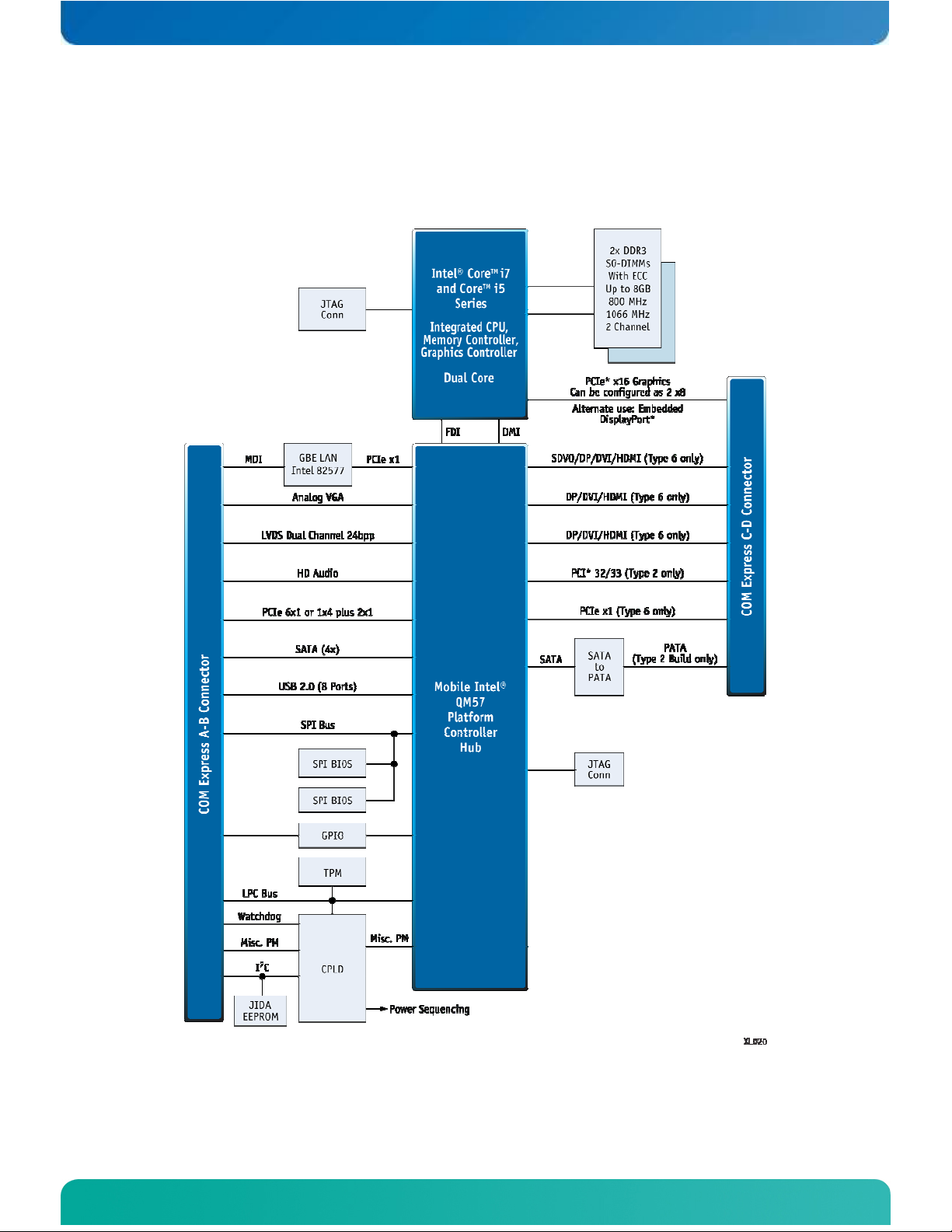
3.2 Functional Block Diagram
Figure 1 is the ETXexpress®-AI COM block diagram
Figure 1: ETXexpress®-AI COM Block Diagram
10
Page 16
Kontron ETXexpress-AI User’s Guide
3.3 Mechanical Specifications
Module Dimensions
» 125 mm x 95 mm ±0.2 mm
Height on Top
» Approximately 3.5 mm maximum (without the PCB)
» Height varies depending on whether the optional cooling solution (either a
passive heatsink or a heat spreader plate) is installed
Height on Bottom
» Approximately 4.06 mm maximum (without the PCB)
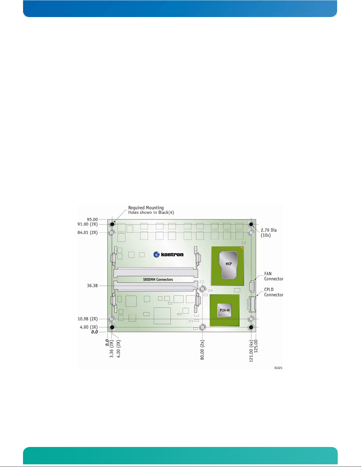
Figure 2 is the ETXexpress®-AI COM mechanical drawing
Figure 2: ETXexpress®-AI COM Mechanical Drawing
All dimensions are shown in millimeters. The COM Express™ specification says
that these holes should be ± 0.25mm [±0.010"], unless otherwise noted. The
tolerances for placement of the COM Express connector with respect to the peg
holes (dimensions [16.50, 6.00]) should be ± 0.10mm [±0.004. The pads are
tied to the PCB ground plane.
11
Page 17

Kontron ETXexpress-AI User’s Guide
V_
V_
3.4 Electrical Specifications
3.4.1 Supply Voltage
» 8 V to 18 V wide range power supply DC in single supply mode (AT)
» 12V + 5VSB ±5% in ATX mode
Power Supply Risetime
» The input voltages rise from ≤10% of nominal to within the regulation
ranges within 0.1ms to 20ms.
» There is a smooth and continuous ramp with each DC input voltage from 10%
to 90% of its final set-point, as required in the ATX specification
Supply Voltage Ripple
» Maximum 100 mV peak to peak 0-20MHz
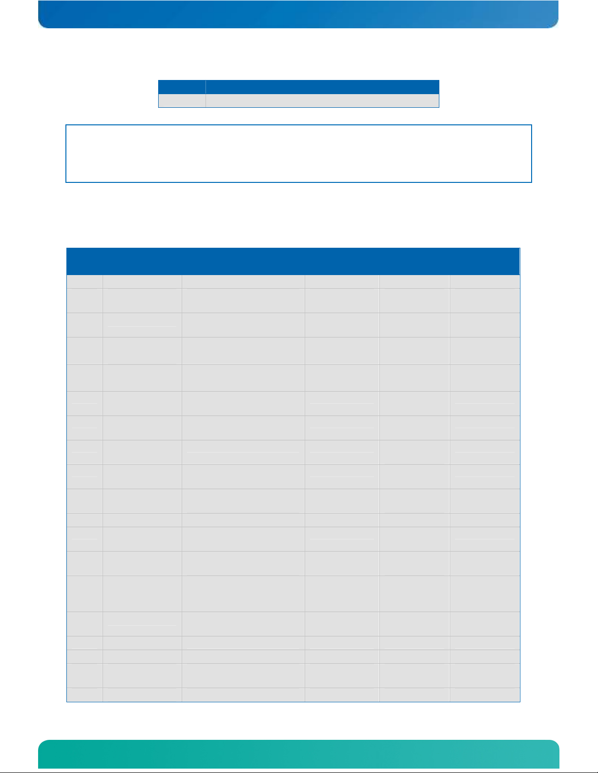
3.4.2 Supply Current (Windows XP SP3)
The testing performed to capture the supply current data used tested modules
mounted on a Kontron evaluation board with a mouse and keyboard connected.
The power consumption tests were executed in Windows XP (with SP3) using a
tool to stress the CPU at 100% load. The power measurement values were
captured after 15 minutes of full load or a stable CPU core temperature of
90°C. To ensure a stable die temperature, a corresponding heatsink was used
to hold the temperature under the critical trip point. All boards were
equipped with a 2x1024-MB DDR3 SDRAM with ECC. The modules were tested using
the maximum CPU frequency. For more detailed information, refer to the “Power
Consumption” diagrams on the EMD Customer section of the Kontron website.
Table 1: Supply Current Test Results
Test Description
Win XP desktop 5.045 V (260
Win XP Burn-In Test 5.042 V (258
Win XP TAT (Max) 5.040 V (296
S3 WOL disabled 5.077 V (225
S3 WOL enabled 5.069 V (276
DOS prompt 5.043 V (258
Linux KDE desktop 5.046 V (272 11.58 V 14.69 W
5P0_SBY
mA)
mA)
mA)
mA)
mA)
mA)
12P0 Results
11.85 V
(1.16 A)
11.79 V
(1.74 A)
11.75 V
(2.02 A)
0.043 V
(0.00 A)
0.043 V
(0.00 A)
11.82 V
(1.41 A)
15.06 W
21.82 W
25.23 W
1.142 W
1.399 W
17.97 W
12
Page 18

Kontron ETXexpress-AI User’s Guide
mA) (1.15 A)
S5 with Ethernet 5.084 V (169
mA)
Power on inrush
current
5.030 V (291
mA)
0.045 V
(0.00 A)
11.80 V
(1.66 A)
0.859 W
21.05 W
Note: It is difficult to test for all possible applications on the market.
There may be an application that draws more power from the CPU than the
values measured in the table above. Take this into consideration if you
are at the limit of the thermal specification, in which case you should
consider improving your thermal solution.
3.5 Environmental Specifications
Temperature
Operating: (with Kontron active heatsink):
» Ambient temperature: 0 to 60°C
» Maximum heat spreader-plate temperature: 0 to 60°C(*)
» Non-operating: -30 to +85°C
NOTE: *The maximum operating temperature with the active heat sink
installed is the maximum measurable temperature on any spot on the heat
spreader surface. You must maintain the temperature according to the
specification above.
Humidity
» Operating: 10% to 90% (non-condensing)
» Non operating: 5% to 95% (non-condensing)
3.6 MTBF
The MTBF is 179,152 hours.
13
Page 19
Kontron ETXexpress-AI User’s Guide
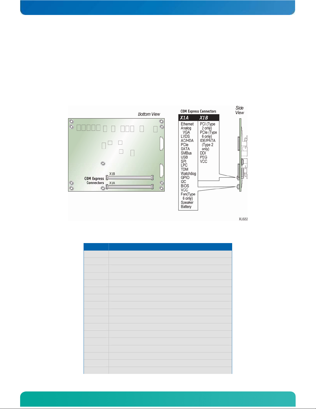
4 COM Connectors
The pin-outs for ETXexpress® interface connectors X1A and X1B are documented
for convenient reference. See the PICMG COM Express™ Specification on the
PICMG website and COM Express™ Design Guide on the Kontron website for
detailed, design-level information.
Figure 3: COM Express Connector Locations
Table 2: General Signal Description
Type Description
I/O-3.3
I/O-5T
I/O-5
I-3.3
I/OD
I-5T
OA
OD
O-1.8
O-3.3
O-5
DP-I/O
DP-I
DP-O
PU
PD
PWR
Bi-directional 3,3 V IO-Signal
Bi-dir. 3,3V I/O (5V Tolerance)
Bi-directional 5V I/O-Signal
3,3V Input
Bi-directional Input/Output Open Drain
3,3V Input (5V Tolerance)
Output Analog
Output Open Drain
1.8V Output
3.3V Output
5V Output
Differential Pair Input/Output
Differential Pair Input
Differential Pair Output
Pull-Up Resistor
Pull-Down Resistor
Power Connection
14
Page 20
Kontron ETXexpress-AI User’s Guide
Type Description
nc
Not connected, signal not available
Note: To protect external power lines of peripheral devices, make sure
that the wires have the right diameter to withstand the maximum
available current and the enclosure of the peripheral device fulfills
the fire-protection requirements in IEC/EN60950
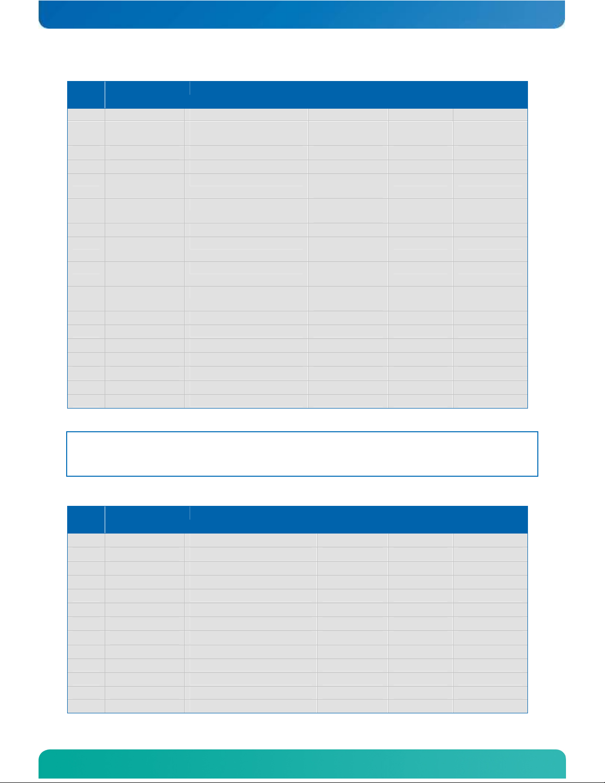
4.1 COM Express™ Type 2 Pin-Outs
Table 3: Type 2 Connector X1A - Row A
Pin Signal Description Type Terminatio
n
A1
A2
A3
A4
A5
A6
A7
A8
A9
A10
A11
A12
A13
A14
A15
A16
A17
A18
A19
GND (Fixed)
GBE0_MDI3-
GBE0_MDI3+
GBE0_LINK10
0#
GBE0_LINK10
00#
GBE0_MDI2-
GBE0_MDI2+
GBE0_LINK#
GBE0_MDI1-
GBE0_MDI1+
GND (Fixed)
GBE0_MDI0-
GBE0_MDI0+
GBE0_CTREF
SUS_S3#
SATA0_TX+
SATA0_TXSUS_S4#
SATA0_RX+
Power Ground PWR - -
Ethernet Receive
DataEthernet Receive
Data+
Ethernet Speed LED
100Mbps
Ethernet Speed LED
1000Mbps
Ethernet Receive
DataEthernet Receive
Data+
LAN Link LED OD Intel®
Ethernet Receive
DataEthernet Receive
Data+
Power Ground PWR - -
Ethernet Transmit
DataEthernet Transmit
Data+
LAN Reference Voltage O-3.3 controlled
Indicates Suspend to
RAM state
SATA 0 Transmit Data+ DP-O -
SATA 0 Transmit Data- DP-O -
Indicates Suspend to
Disk state
SATA 0 Receive Data+ DP-I
DP-I Intel®
82577
DP-I Intel®
82577
O-3.3 Intel®
82577
O-3.3 Intel®
82577
DP-I Intel®
82577
DP-I Intel®
82577
82577
DP-I Intel®
82577
DP-I Intel®
82577
DP-O Intel®
82577
DP-O Intel®
82577
on a power
rail
O-3.3 CPLD I/O CPLD I/O
O-3.3 CPLD I/O CPLD I/O
Comment
-
-
-
-
-
-
-
-
-
-
-
-
15
Page 21

Kontron ETXexpress-AI User’s Guide
Pin Signal Description Type Terminatio
n
A20
A21
SATA0_RXGND (Fixed)
A22 SATA2_TX+
A23
A24
A25
A26
A27
A28
A29
A30
A31
A32
SATA2_TXSUS_S5#
SATA2_RX+
SATA2_RX-
BATLOW#
(S)ATA_ACT#
AC/HDA_SYNC
AC/HDA_RST#
GND Fixed)
AC/HDA_BITC
SATA 0 Receive Data- DP-I -
Power Ground PWR -
SATA 2 Transmit Data- DP-O
SATA 2 Transmit Data+ DP-O
Indicates Soft Off
state
SATA 2 Receive Data+ Not
SATA 2 Receive Data- Not
Indicates low
external battery
SATA, IDE, SD
Activity Indicator
HD Audio Sync O-3.3
HD Audio Reset O-3.3
Power Ground PWR - -
HD Audio Clock O-3.3
O-3.3 CPLD I/O CPLD I/O
connected
connected
I-3.3 CPLD I/O
O-3.3 Buffered
nc nc
nc nc
Output
LK
A33
AC/HDA_SDOU
HD Audio Data O-3.3
T
A34 BIOS_DIS0#
A35
A36
A37
A38
A39
A40
A41
A42
A43
A44
A45
A46
A47
A48
THRMTRIP#
USB6USB6+
USB_6_7_OC#
USB4USB4+
GND (Fixed)
USB2USB2+
USB_2_3_OC#
USB0USB0+
VCC_RTC
EXCD0_PERST
#
A49
A50
EXCD0_CPPE#
LPC_SERIRQ
Disable Module BIOS.
Enables boot from a
BIOS on Baseboard
CPU thermal shutdown
indicator
USB Data- Port #6 DP-I/O -
USB Data+ Port #6 DP-I/O -
USB Overcurrent Pair
6/7
USB Data- Port #4 DP-I/O
USB Data+ Port #4 DP-I/O -
Power Ground PWR - -
USB Data- Port #2
USB Data+ Port #2 DP-I/O
USB Overcurrent Pair
2/3
USB Data- Port #0 DP-I/O
USB Data+ Port #0 DP-I/O
RTC Power Supply +3V PWR - -
PCIe Express Card 0
Reset
PCIe Express Card 0
Request
LPC Serial Interrupt
Request
I-3.3
O-3.3
I-3.3
I-3.3
O-3.3
I-3.3
IO-3.3
Comment
16
Page 22

Kontron ETXexpress-AI User’s Guide
Pin Signal Description Type Terminatio
n
A51
A52
A53
A54
A55
A56
A57
A58
A59
A60
A61
A62
A63
A64
A65
A66
A67
GND (Fixed)
PCIE_TX5+
PCIE_TX5GPI0
PCIE_TX4+
PCIE_TX4GND (Fixed)
PCIE_TX3+
PCIE_TX3GND (Fixed)
PCIE_TX2+
PCIE_TX2GPI1
PCIE_TX1+
PCIE_TX1GND (Fixed)
GPI2
Power Ground PWR - -
PCIe 5 Transmit Data+ DP-O
PCIe 5 Transmit Data- DP-O
General Purpose Input 0 I-3.3
PCIe 4 Transmit Data+ DP-O
PCIe 4 Transmit Data- DP-O
Power Ground PWR - -
PCIe 3 Transmit Data+ DP-O
PCIe 3 Transmit Data- DP-O
Power Ground PWR - -
PCIe 2 Transmit Data+ DP-O
PCIe 2 Transmit Data- DP-O
General Purpose Input 1 I-3.3
PCIe 1 Transmit Data+ DP-O
PCIe 1 Transmit Data- DP-O
Power Ground PWR - -
General Purpose Input 2 I-3.3
Comment
A68
A69
A70
A71
A72
A73
A74
A75
A76
A77
A78
A79
A80
A81
A82
PCIE_TX0+
PCIE_TX0-
GND (Fixed)
LVDS_A0+
LVDS_A0-
LVDS_A1+
LVDS_A1-
LVDS_A2+
LVDS_A2-
LVDS_VDD_EN
LVDS_A3+
LVDS_A3-
GND (Fixed)
LVDS_A_CK+
LVDS_A_CK-
PCIe lane #0
Transmit+
PCIe lane #0
TransmitPower Ground PWR - -
LVDS Channel A
(positive)
LVDS Channel A
(negative)
LVDS Channel A
(positive)
LVDS Channel A
(negative)
LVDS Channel A
(positive)
LVDS Channel A
(negative)
LVDS Panel Power
Controller
LVDS Channel A
(positive)
LVDS Channel A
(negative)
Power Ground PWR - -
LVDS Channel A Clock+ DP-O
LVDS Channel A Clock- DP-O
DP-O
DP-O
DP-O
DP-O -
DP-O -
DP-O
DP-O
DP-O
O-3.3
DP-O
DP-O
17
Page 23

Kontron ETXexpress-AI User’s Guide
Pin Signal Description Type Terminatio
n
A83
A84
LVDS_I2C_CK
LVDS_I2C_DA
LVDS I2C Clock IO-3.3
LVDS I2C Data IO-3.3
T
A85
A86
A87
A88
GPI3
KBD_RST#
KBD_A20GATE
PCIE0_CK_RE
General Purpose Input 3 I-3.3
Keyboard Reset I-3.3
A20 gate I-3.3
PCIe Clock (positive) DP-O
F+
A89
PCIE0_CK_RE
PCIe Clock (negative) DP-O
F-
A90
A91
A92
A93
A94
A95
A96
A97
A98
A99
A100
A101
A102
A103
A104
A105
A106
A107
A108
A109
A110
GND (Fixed)
SPI_Power
SPI_MISO
GPO0
SPI_CLK
SPI_MOSI
GND
TYPE10#
RSVD
RSVD
GND (Fixed)
RSVD
RSVD
RSVD
VCC_12V
VCC_12V
VCC_12V
VCC_12V
VCC_12V
VCC_12V
GND
Power Ground PWR - -
Power for off-board
SPI flash
SPI Master In Slave
Out data line
General Purpose
Output 0
SPI clock line for
off-board SPI
SPI Master Out Slave
In data line
Power Ground PWR - -
Not
Reserved Not
Reserved Not
Power Ground PWR - -
Reserved Not
Reserved Not
Reserved Not
12V VCC PWR - -
12V VCC PWR - -
12V VCC PWR - -
12V VCC PWR - -
12V VCC PWR - -
12V VCC PWR - -
Power Ground PWR - -
O-3.3
I-3.3
O-3.3
O-3.3
O-3.3 -
nc nc
connected
nc nc
connected
nc nc
connected
nc nc
connected
nc nc
connected
nc nc
connected
Comment
18
Page 24

Kontron ETXexpress-AI User’s Guide
Table 4: Type 2 Connector X1A - Row B
Pin Signal Description Type Terminati
on
B1
B2
B3
B4
B5
B6
B7
B8
B9
B10
B11
B12
B13
B14
B15
B16
B17
B18
B19
B20
B21
B22
B23
B24
B25
B26
B27
B28
B29
GND (Fixed)
GBE0_ACT#
LPC_FRAME#
LPC_AD0
LPC_AD1
LPC_AD2
LPC_AD3
LPC_DRQ0#
LPC_DRQ1#
LPC_CLK
GND (Fixed)
PWRBTN#
SMB_CLK
SMB_DAT
SMB_ALERT#
SATA1_TX+
SATA1_TX-
SUS_STAT#
SATA1_RX+
SATA1_RX-
GND (Fixed)
SATA3_TX+
SATA3_TX-
PWR_OK
SATA3_RX+
SATA3_RX-
WDT
AC/HDA_SDIN
2
AC/HDA_SDIN
1
Power Ground PWR - -
Ethernet Activity LED Not
connected
LPC Frame Indicator O-3.3
LPC Address / Data
Bus
LPC Address / Data
Bus
LPC Address / Data
Bus
LPC Address / Data
Bus
LPC Serial DMA
Request
LPC Serial DMA
Request
LPC Clock O-3.3
Power Ground PWR - -
Power Button Input I-3.3
SMBus Clock O-3.3
SMBus Data IO-3.3
SMBus Interrupt IO-3.3
SATA 1 Transmit Data+ DP-O
SATA 1 Transmit Data- DP-O
Indicates imminent
suspend operation;
used to notify LPC
devices.
SATA 1 Receive Data+ DP-I
SATA 1 Receive Data- DP-I
Power Ground PWR - -
SATA 3 Transmit Data+ DP-O
SATA 3 Transmit Data- DP-O
Power OK from power
supply
SATA 3 Receive Data+ DP-I
SATA 3 Receive Data- DP-I
Indicator for
Watchdog Timeout
Audio CODEC Serial
Data In 2
Audio CODEC Serial
Data in 1
IO-3.3
IO-3.3
IO-3.3
IO-3.3
I-3.3
I-3.3
O-3.3
I-3.3
O-3.3
I-3.3
I-3.3
nc nc
Comment
19
Page 25

Kontron ETXexpress-AI User’s Guide
Pin Signal Description Type Terminati
on
B30
B31
B32
B33
B34
B35
B36
B37
B38
B39
B40
B41
B42
B43
B44
B45
B46
B47
B48
B49
B50
B51
B52
B53
B54
B55
B56
B57
B58
B59
B60
B61
B62
B63
AC/HDA_SDIN
0
GND (Fixed)
SPKR
I2C_CK
I2C_DAT
THRM#
USB7USB7+
USB_4_5_OC#
USB5-
USB5+
GND (Fixed)
USB3USB3+
USB_0_1_OC#
USB1USB1+
EXCD1_PERST
#
EXCD1_CPPE#
SYS_RESET#
CB_RESET#
GND (Fixed)
PCIE_RX5+
PCIE_RX5-
GPO1
PCIE_RX4+
PCIE_RX4-
GPO2
PCIE_RX3+
PCIE_RX3-
GND (Fixed)
PCIE_RX2+
PCIE_RX2-
GPO3
Audio CODEC Serial
Data in 0
Power Ground PWR - -
Speaker Interface O-3.3
I2C Clock IO-3.3
I2C Data IO-3.3
Over Temperature
Indicator
USB Data- Port #7 ( DP-I/O
USB Data+ Port #7 DP-I/O
USB Overcurrent Pair
4/5
USB Data- Port #5 DP-I/O
USB Data+ Port #5 DP-I/O
Power Ground PWR - -
USB Data- Port #3 DP-I/O
USB Data+ Port #3 DP-I/O
USB Overcurrent Pair
0/1
USB Data- Port #1 DP-I/O
USB Data+ Port #1 DP-I/O
PCIe Express Card 1
Reset
PCIe Express Card 1
Request
Reset button input I-3.3
Carrier Board Reset O-3.3
Power Ground PWR - -
PCIe 5 Receive Data+ DP-I
PCIe 5 Receive Data- DP-I
General Purpose
Output 1
PCIe 4 Receive Data+ DP-I
PCIe 4 Receive Data- DP-I
General Purpose
Output 2
PCIe 3 Receive Data+ DP-I
PCIe 5 Receive Data- DP-I
Power Ground PWR - -
PCIe 2 Receive Data+ DP-I
PCIe 2 Receive Data- DP-I
General Purpose O-3.3
I-3.3
I-3.3
I-3.3
I-3.3
O-3.3
I-3.3
O-3.3
O-3.3
Comment
20
Page 26

Kontron ETXexpress-AI User’s Guide
Pin Signal Description Type Terminati
on
Output 3
B64
B65
B66
B67
B68
B69
B70
B71
B72
B73
B74
B75
B76
B77
B78
B79
PCIE_RX1+
PCIE_RX1-
WAKE0#
WAKE1#
PCIE_RX0+
PCIE_RX0GND (Fixed)
LVDS_B0+
LVDS_B0-
LVDS_B1+
LVDS_B1-
LVDS_B2+
LVDS_B2-
LVDS_B3+
LVDS_B3-
LVDS_BKLT_E
PCIe 1 Receive Data+ DP-I
PCIe 1 Receive Data- DP-I
PCI Express Wake
Event
General Purpose Wake
Event
PCIe lane #0 Receive+ DP-I
PCIe lane #0 Receive- DP-I
Power Ground PWR - -
LVDS Channel B
(Positive)
LVDS Channel B
(Negative)
LVDS Channel B
(Positive)
LVDS Channel B
(Negative)
LVDS Channel B
(Positive)
LVDS Channel B
(Negative)
LVDS Channel B
(Positive)
LVDS Channel B
(Negative)
Backlight Enable O-3.3
I-3.3
I-3.3
DP-O
DP-O
DP-O
DP-O
DP-O
DP-O
DP-O
DP-O
N
B80
B81
B82
B83
B84
B85
B86
B87
B88
B89
B90
B91
B92
B93
B94
GND (Fixed)
LVDS_B_CK+
LVDS_B_CKLVDS_BKLT_C
TRL
VCC_5V_SBY
VCC_5V_SBY
VCC_5V_SBY
VCC_5V_SBY
BIOS_DIS1#
VGA_RED
GND (Fixed)
VGA_GRN
VGA_BLU
VGA_HSYNC
VGA_VSYNC
Power Ground PWR - -
LVDS Channel B Clock+ DP-O
LVDS Channel B Clock- DP-O
Backlight Brightness
Control
+5V Standby PWR - -
+5V Standby PWR - -
+5V Standby PWR - -
+5V Standby PWR - -
BIOS Disable 1
(offboard SPI select)
Analog Video Red O
Power Ground PWR - -
Analog Video Green O
Analog Video Blue O
Analog Video
Horizontal Sync
Analog Video Vertical O-3.3
O-3.3
I-3.3
O-3.3
Comment
21
Page 27
Kontron ETXexpress-AI User’s Guide
Pin Signal Description Type Terminati
on
Sync
B95
B96
B97
B98
B99
B100
B101
B102
B103
B104
B105
B106
B107
B108
B109
B110
VGA_I2C_CK
VGA_I2C_DAT
SPI_CS#
RSVD
RSVD
GND (Fixed)
RSVD
RSVD
RSVD
VCC_12V_16
VCC_12V_17
VCC_12V_18
VCC_12V_19
VCC_12V_20
VCC_12V_21
GND (Fixed)
Analog Video I2C
Clock
Analog Video I2C Data IO/OD-3.3
SPI Chip Select O-3.3
Reserved Not
Reserved Not
Power Ground PWR - -
Reserved Not
Reserved Not
Reserved Not
12V VCC PWR - -
12V VCC PWR - -
12V VCC PWR - -
12V VCC PWR - -
12V VCC PWR - -
12V VCC PWR - -
Power Ground PWR
IO/OD-3.3
nc nc
connected
nc nc
connected
nc nc
connected
nc nc
connected
Nc Nc
connected
Comment
Note: The termination resistors in this table are already mounted on the
ETXexpress® board. Refer to the PICMG COM Express™ Design Guide for
information about additional termination resistors.
Table 5: Connector X1B - Row C
Pin Signal Description Type Terminati
on
C1
C2
C3
C4
C5
C6
C7
C8
C9
C10
C11
C12 IDE_D14 IDE Data Bus I/O-5T
C13
GND (Fixed)
IDE_D7
IDE_D6
IDE_D3
IDE_D15
IDE_D8
IDE_D9
IDE_D2
IDE_D13
IDE_D1
GND (Fixed)
IDE_IORDY
Power Ground PWR - -
IDE Data Bus I/O-5T
IDE Data Bus I/O-5T
IDE Data Bus I/O-5T
IDE Data Bus I/O-5T
IDE Data Bus I/O-5T
IDE Data Bus I/O-5T
IDE Data Bus I/O-5T
IDE Data Bus I/O-5T
IDE Data Bus I/O-5T
Power Ground PWR - -
IDE I/O Ready I-5T
Comment
22
Page 28

Kontron ETXexpress-AI User’s Guide
Pin Signal Description Type Terminati
on
C14
C15
C16
C17
C18
C19
C20
C21
C22
C23
C24
C25
C26
C27
C28
C29
C30
C31
C32
C33
C34
C35
C36
C37
C38
C39
C40
C41
C42
C43
C44
IDE_IOR#
PCI_PME#
PCI_GNT2#
PCI_REQ2#
PCI_GNT1#
PCI_REQ1#
PCI_GNT0#
GND (Fixed)
PCI_REQ0#
PCI_RST#
PCI_AD0
PCI_AD2
PCI_AD4
PCI_AD6
PCI_AD8
PCI_AD10
PCI_AD12
GND (Fixed)
PCI_AD14
PCI_C/BE1#
PCI_PERR#
PCI_LOCK#
PCI_DEVSEL#
PCI_IRDY#
PCI_C/BE2#
PCI_AD17
PCI_AD19
GND (Fixed)
PCI_AD21
PCI_AD23
PCI_C/BE3#
IDE I/O Read O-3.3
PCI Power Management I-3.3
PCI Bus Grant 2 O-3.3
PCI Bus Request 2 I-5T
PCI Bus Grant 1 O-3.3
PCI Bus Request 1 I-5T
PCI Bus Grant 0 O-3.3
Power Ground PWR - -
PCI Bus Request 0 I-5T
PCI Bus Reset O-3.3
PCI Address & Data Bus
line
PCI Address & Data Bus
line
PCI Address & Data Bus
line
PCI Address & Data Bus
line
PCI Address & Data Bus
line
PCI Address & Data Bus
line
PCI Address & Data Bus
line
Power Ground PWR - -
PCI Address & Data Bus
line
PCI Bus Command & Byte
Enable 1
PCI Bus Grant Error I/O-5T
PCI Bus Lock I/O-5T
PCI Bus Device Select I/O-5T
PCI Bus Initiator
Ready
PCI Bus Command & Byte
Enable 2
PCI Address & Data Bus
line
PCI Address & Data Bus
line
Power Ground PWR - -
PCI Address & Data Bus
line
PCI Address & Data Bus
line
PCI Bus Command & Byte
Enable 3
I/O-5T
I/O-5T
I/O-5T
I/O-5T
I/O-5T
I/O-5T
I/O-5T
I/O-5T
I/O-5T
I/O-5T
I/O-5T
I/O-5T
I/O-5T
I/O-5T
I/O-5T
I/O-5T
Comment
23
Page 29

Kontron ETXexpress-AI User’s Guide
Pin Signal Description Type Terminati
on
C45
C46
C47
C48
C49
C50
C51
C52
C53
C54
C55
C56
C57
C58
C59
C60
C61
C62
C63
C64
C65
PCI_AD25
PCI_AD27
PCI_AD29
PCI_AD31
PCI_IRQA#
PCI_IRQB#
GND (Fixed)
PEG_RX0+
PEG_RX0-
TYPE0#
PEG_RX1+
PEG_RX1-
TYPE1#
PEG_RX2+
PEG_RX2-
GND (Fixed)
PEG_RX3+
PEG_RX3-
RSVD
RSVD
PEG_RX4+
PCI Address & Data Bus
line
PCI Address & Data Bus
line
PCI Address & Data Bus
line
PCI Address & Data Bus
line
PCI Bus Interrupt
Request A
PCI Bus Interrupt
Request B
Power Ground PWR - -
PCI Express Graphics
Receive Lane 0
Positive
PCI Express Graphics
Receive Lane 0
Negative
Not connected for Type
2 module
PCI Express Graphics
Receive Lane 1
Positive
PCI Express Graphics
Receive Lane 1
Negative
Not connected for Type
2 module
PCI Express Graphics
Receive Lane 2
Positive
PCI Express Graphics
Receive Lane 2
Negative
Power Ground PWR - -
PCI Express Graphics
Receive Lane 3
Positive
PCI Express Graphics
Receive Lane 3
Negative
Reserved Not
Reserved Not
PCI Express Graphics DP-I
I/O-5T
I/O-5T
I/O-5T
I/O-5T
I-5T
I-5T
DP-I
DP-I
Not
connected
DP-I
DP-I
Not
connected
DP-I
DP-I
DP-I
DP-I
connected
connected
nc nc
nc nc
nc nc
nc nc-
Comment
24
Page 30

Kontron ETXexpress-AI User’s Guide
Pin Signal Description Type Terminati
on
Receive Lane 4
Positive
C66
C67
C68
C69
C70
C71
C72
C73
C74
C75
C76
C77
C78
C79
C80
C81
PEG_RX4-
RSVD
PEG_RX5+
PEG_RX5-
GND (Fixed)
PEG_RX6+
PEG_RX6-
SDVO_DATA
PEG_RX7+
PEG_RX7-
GND (Fixed)
RSVD
PEG_RX8+
PEG_RX8-
GND (Fixed)
PEG_RX9+
PCI Express Graphics
Receive Lane 4
Negative
Reserved Not
PCI Express Graphics
Receive Lane 5
Positive
PCI Express Graphics
Receive Lane 5
Negative
Power Ground PWR - -
PCI Express Graphics
Receive Lane 6
Positive
PCI Express Graphics
Receive Lane 6
Negative
SDVOController Data Not
PCI Express Graphics
Receive Lane 7
Positive
PCI Express Graphics
Receive Lane 7
Negative
Power Ground PWR - -
Reserved Not
PCI Express Graphics
Receive Lane 8
Positive
PCI Express Graphics
Receive Lane 8
Negative
Power Ground PWR - -
PCI Express Graphics
Receive Lane 9
Positive
DP-I
nc nc
connected
DP-I
DP-I
DP-I
DP-I
nc nc
connected
DP-I
DP-I
nc nc
connected
DP-I
DP-I
DP-I
Comment
25
Page 31

Kontron ETXexpress-AI User’s Guide
Pin Signal Description Type Terminati
on
C82
C83
C84
C85
C86
C87
C88
C89
C90
C91
C92
C93
C94
C95
C96
C97
C98
C99
PEG_RX9-
RSVD
GND
PEG_RX10+
PEG_RX10-
GND
PEG_RX11+
PEG_RX11-
GND (Fixed)
PEG_RX12+
PEG_RX12-
GND
PEG_RX13+
PEG_RX13-
GND
RSVD
PEG_RX14+
PEG_RX14-
PCI Express Graphics
Receive Lane 9
Negative
Reserved Not
Power Ground PWR - -
PCI Express Graphics
Receive Lane 10
Positive
PCI Express Graphics
Receive Lane 10
Negative
Power Ground PWR - -
PCI Express Graphics
Receive Lane 11
Positive
PCI Express Graphics
Receive Lane 11
Negative
Power Ground PWR - -
PCI Express Graphics
Receive Lane 12
Positive
PCI Express Graphics
Receive Lane 12
Negative
Power Ground PWR - -
PCI Express Graphics
Receive Lane 13
Positive
PCI Express Graphics
Receive Lane 13
Negative
Power Ground PWR - -
Reserved Not
PCI Express Graphics
Receive Lane 14
Positive
PCI Express Graphics DP-I
DP-I
nc nc
connected
DP-I
DP-I
DP-I
DP-I
DP-I
DP-I
DP-I
DP-I
nc nc
connected
DP-I
Comment
26
Page 32

Kontron ETXexpress-AI User’s Guide
Pin Signal Description Type Terminati
on
Receive Lane 14
Negative
C100
C101
C102
C103
C104
C105
C106
C107
C108
C109
C110
GND (Fixed)
PEG_RX15+
PEG_RX15-
GND
VCC_12V
VCC_12V
VCC_12V
VCC_12V
VCC_12V
VCC_12V
GND (Fixed)
Power Ground PWR - -
PCI Express Graphics
Receive Lane 15
Positive
PCI Express Graphics
Receive Lane 15
Negative
Power Ground PWR - -
12V VCC PWR - -
12V VCC PWR - -
12V VCC PWR - -
12V VCC PWR - -
12V VCC PWR 8 - -
12V VCC PWR - -
Power Ground PWR - -
DP-I
DP-I
Comment
Note: The termination resistors in this table are already mounted on the
ETXexpress® board. Refer to the PICMG COM Express™ Design Guide for
information about additional termination resistors.
Table 6: Type 2 Connector X1B - Row D
Pin Signal Description Type Terminatio
n
D1
D2
D3
D4
D5
D6
D7
D8
D9
D10
D11
D12
D13
GND (Fixed)
IDE_D5
IDE_D10
IDE_D11
IDE_D12
IDE_D4
IDE_D0
IDE_REQ
IDE_IOW#
IDE_ACK#
GND (Fixed)
IDE_IRQ
IDE_A0
Power Ground PWR - -
IDE Data Bus I/O-5T
IDE Data Bus I/O-5T
IDE Data Bus I/O-5T
IDE Data Bus I/O-5T
IDE Data Bus I/O-5T
IDE Data Bus I/O-5T
IDE Data Bus I/O-5T
IDE IO Write O-3.3
IDE DMA
Acknowledge
Power Ground PWR - -
IDE Interrupt
Request
IDE Address Bus O-3.3
O-3.3
I-5T
Comment
27
Page 33

Kontron ETXexpress-AI User’s Guide
Pin Signal Description Type Terminatio
n
D14
D15
D16
D17
D18
D19
D20
D21
D22
D23
D24
D25
D26
D27
D28
D29
D30
D31
D32
D33
D34
D35
D36
D37
D38
D39
D40
D41
IDE_A1
IDE_A2
IDE_CS1#
IDE_CS3#
IDE_RESET#
PCI_GNT3#
PCI_REQ3#
GND (Fixed)
PCI_AD1
PCI_AD3
PCI_AD5
PCI_AD7
PCI_C/BE0#
PCI_AD9
PCI_AD11
PCI_AD13
PCI_AD15
GND (Fixed)
PCI_PAR
PCI_SERR#
PCI_STOP#
PCI_TRDY#
PCI_FRAME#
PCI_AD16
PCI_AD18
PCI_AD20
PCI_AD22
GND (Fixed)
IDE Address Bus O-3.3
IDE Address Bus O-3.3
IDE Chip Select
Channel 0
IDE Chip Select
Channel 1
IDE Hard Drive
Reset
PCI Bus Grant 3 O-3.3
PCI Bus Request 3 I-5T
Power Ground PWR - -
PCI Address &
Data Bus line
PCI Address &
Data Bus line
PCI Address &
Data Bus line
PCI Address &
Data Bus line
PCI Bus Command
& Byte Enable 0
PCI Address &
Data Bus line
PCI Address &
Data Bus line
PCI Address &
Data Bus line
PCI Address &
Data Bus line
Power Ground PWR - -
PCI Bus Parity I/O-5T
PCI Bus System
Error
PCI Bus Stop I/O-5T
PCI Bus Target
Ready
PCI Bus Cycle
Frame
PCI Address &
Data Bus line
PCI Address &
Data Bus line
PCI Address &
Data Bus line
PCI Address &
Data Bus line
Power Ground PWR - -
O-3.3
O-3.3
O-3.3
I/O-5T
I/O-5T
I/O-5T
I/O-5T
I/O-5T
I/O-5T
I/O-5T
I/O-5T
I/O-5T
I/O-5T
I/O-5T
I/O-5T
I/O-5T
I/O-5T
I/O-5T
I/O-5T
Comment
28
Page 34

Kontron ETXexpress-AI User’s Guide
Pin Signal Description Type Terminatio
n
D42
D43
D44
D45
D46
D47
D48
D49
D50
D51
D52
D53
D54
D55
D56
D57
D58
D59
D60
PCI_AD24
PCI_AD26
PCI_AD28
PCI_AD30
PCI_IRQC#
PCI_IRQD#
PCI_CLKRUN#
PCI_M66EN
PCI_CLK
GND (Fixed)
PEG_TX0+
PEG_TX0-
PEG_LANE_RV
#
PEG_TX1+
PEG_TX1-
TYPE2#
PEG_TX2+
PEG_TX2-
GND (Fixed)
PCI Address &
Data Bus line
PCI Address &
Data Bus line
PCI Address &
Data Bus line
PCI Address &
Data Bus line
PCI Bus
Interrupt
Request C
PCI Bus
Interrupt
Request D
PCI Clock Run O-3.3
PCI_M66EN I-5T
PCI Clock 33MHz O-3.3
Power Ground PWR - -
PCI Express
Graphics
Transmit Data
Lane 0 Positive
PCI Express
Graphics
Transmit Data
Lane 0 Negative
PCI Express
Graphics Lane
Reversal Input
strap
PCI Express
Graphics
Transmit Data
Lane 1 Positive
PCI Express
Graphics
Transmit Data
Lane 1 Negative
Pulled low for
Type 2 modules
PCI Express
Graphics
Transmit Data
Lane 2 Positive
PCI Express
Graphics
Transmit Data
Lane 2 Negative
Power Ground PWR - -
I/O-5T
I/O-5T
I/O-5T
I/O-5T
I-5T
I-5T
DP-O
DP-O
I-3.3
DP-O
DP-O
PDS
DP-O
DP-O
Comment
29
Page 35

Kontron ETXexpress-AI User’s Guide
Pin Signal Description Type Terminatio
n
D61
D62
D63
D64
D65
D66
D67
D68
D69
D70
D71
D72
D73
D74
D75
D76
D77
PEG_TX3+
PEG_TX3-
RSVD
RSVD
PEG_TX4+
PEG_TX4-
GND
PEG_TX5+
PEG_TX5-
GND (Fixed)
PEG_TX6+
PEG_TX6-
SDVO_CLK
PEG_TX7+
PEG_TX7-
GND
IDE_CBLID
PCI Express
Graphics
Transmit Data
Lane 3 Positive
PCI Express
Graphics
Transmit Data
Lane 3 Negative
Reserved Not connected nc nc
Reserved Not connected nc nc
PCI Express
Graphics
Transmit Data
Lane 4 Positive
PCI Express
Graphics
Transmit Data
Lane 4 Negative
Power Ground PWR - -
PCI Express
Graphics
Transmit Data
Lane 5 Positive
PCI Express
Graphics
Transmit Data
Lane 5 Negative
Power Ground PWR - -
PCI Express
Graphics
Transmit Data
Lane 6 Positive
PCI Express
Graphics
Transmit Data
Lane 6 Negative
SDVO Clock Not connected nc nc
PCI Express
Graphics
Transmit Data
Lane 7 Positive
PCI Express
Graphics
Transmit Data
Lane 7 Negative
Power Ground PWR - -
40/80-pin IDE
cable ID
DP-O
DP-O
DP-O
DP-O
DP-O
DP-O
DP-O
DP-O
DP-O
DP-O
I-3.3
Comment
30
Page 36

Kontron ETXexpress-AI User’s Guide
Pin Signal Description Type Terminatio
n
D78
D79
D80
D81
D82
D83
D84
D85
D86
D87
D88
D89
D90
D91
D92
D93
D94
PEG_TX8+
PEG_TX8-
GND (Fixed)
PEG_TX9+
PEG_TX9-
RSVD
GND
PEG_TX10+
PEG_TX10-
GND
PEG_TX11+
PEG_TX11-
GND (Fixed)
PEG_TX12+
PEG_TX12-
GND
PEG_TX13+
PCI Express
Graphics
Transmit Data
Lane 8 Positive
PCI Express
Graphics
Transmit Data
Lane 8 Negative
Power Ground PWR - -
PCI Express
Graphics
Transmit Data
Lane 9 Positive
PCI Express
Graphics
Transmit Data
Lane 9 Negative
Reserved Not connected nc nc
Power Ground PWR - -
PCI Express
Graphics
Transmit Data
Lane 10 Positive
PCI Express
Graphics
Transmit Data
Lane 10 Negative
Power Ground PWR - -
PCI Express
Graphics
Transmit Data
Lane 11 Positive
PCI Express
Graphics
Transmit Data
Lane 11 Negative
Power Ground PWR - -
PCI Express
Graphics
Transmit Data
Lane 12 Positive
PCI Express
Graphics
Transmit Data
Lane 12 Negative
Power Ground PWR - -
PCI Express
Graphics
DP-O
DP-O
DP-O
DP-O
DP-O
DP-O
DP-O
DP-O
DP-O
DP-O
DP-O
Comment
31
Page 37

Kontron ETXexpress-AI User’s Guide
Pin Signal Description Type Terminatio
n
Transmit Data
Lane 13 Positive
D95
D96
D97
D98
D99
D100
D101
D102
D103
D104
D105
D106
D107
D108
D109
D110
PEG_TX13-
GND
PEG_ENABLE#
PEG_TX14+
PEG_TX14-
GND (Fixed)
PEG_TX15+
PEG_TX15-
GND
VCC_12V
VCC_12V
VCC_12V
VCC_12V
VCC_12V
VCC_12V
GND (Fixed)
PCI Express
Graphics
Transmit Data
Lane 13 Negative
Power Ground PWR - -
Enable PCI
Express x16
external
Graphics
Interface
PCI Express
Graphics
Transmit Data
Lane 14 Positive
PCI Express
Graphics
Transmit Data
Lane 14 Negative
Power Ground PWR - -
PCI Express
Graphics
Transmit Data
Lane 15 Positive
PCI Express
Graphics
Transmit Data
Lane 15 Negative
Power Ground PWR - -
12V VCC PWR - -
12V VCC PWR - -
12V VCC PWR - -
12V VCC PWR - -
12V VCC PWR - -
12V VCC PWR - -
Power Ground PWR - -
DP-O
I-3.3
DP-O
DP-O
DP-O
DP-O
Comment
Note: The termination resistors in this table are already mounted on the
ETXexpress® board. Refer to the PICMG COM Express™ Design Guide for
information about additional termination resistors.
32
Page 38

Kontron ETXexpress-AI User’s Guide
4.2 COM Express™ Type 6 Pin-Outs
Table 7: Type 6 Connector X1A - Row A
Pin Signal Description Type Termination Comment
A1
A2
A3
A4
A5
A6
A7
A8
A9
A10
A11
A12
A13
A14
A15
A16
A17
A18
A19
A20
A21
A22
A23
A24
GND (Fixed)
GBE0_MDI3-
GBE0_MDI3+
GBE0_LINK10
0#
GBE0_LINK10
00#
GBE0_MDI2-
GBE0_MDI2+
GBE0_LINK#
GBE0_MDI1-
GBE0_MDI1+
GND (Fixed)
GBE0_MDI0-
GBE0_MDI0+
GBE0_CTREF
SUS_S3#
SATA0_TX+
SATA0_TX-
SUS_S4#
SATA0_RX+
SATA0_RX-
GND (Fixed)
SATA2_TX+
SATA2_TX-
SUS_S5#
Power Ground PWR - -
Ethernet Receive
DataEthernet Receive
Data+
Ethernet Speed
LED 100Mbps
Ethernet Speed
LED 1000Mbps
Ethernet Receive
DataEthernet Receive
Data+
LAN Link LED OD Intel® 82577 -
Ethernet Receive
DataEthernet Receive
Data+
Power Ground PWR - -
Ethernet Transmit
DataEthernet Transmit
Data+
LAN Reference
Voltage
Indicates Suspend
to RAM state
SATA 0 Transmit
Data+
SATA 0 Transmit
DataIndicates Suspend
to Disk state
SATA 0 Receive
Data+
SATA 0 Receive
DataPower Ground PWR -
SATA 2 Transmit
DataSATA 2 Transmit
Data+
Indicates Soft
Off state
DP-I Intel® 82577 -
DP-I Intel® 82577 -
O-3.3 Intel® 82577 -
O-3.3 Intel® 82577 -
DP-I Intel® 82577 -
DP-I Intel® 82577 -
DP-I Intel® 82577 -
DP-I Intel® 82577 -
DP-O Intel® 82577 -
DP-O Intel® 82577 -
O-3.3 is on a
power rail
controlled
O-3.3 CPLD I/O CPLD I/O
DP-O -
DP-O -
O-3.3 CPLD I/O CPLD I/O
DP-I
DP-I -
DP-O
DP-O
O-3.3 CPLD I/O CPLD I/O
-
33
Page 39

Kontron ETXexpress-AI User’s Guide
Pin Signal Description Type Termination Comment
A25
A26
A27
A28
A29
A30
A31
A32
SATA2_RX+
SATA2_RX-
BATLOW#
(S)ATA_ACT#
AC/HDA_SYNC
AC/HDA_RST#
GND Fixed)
AC/HDA_BITC
SATA 2 Receive
Data+
SATA 2 Receive
DataIndicates low
external battery
SATA, IDE, SD
Activity
Indicator
HD Audio Sync O-3.3
HD Audio Reset O-3.3
Power Ground PWR - -
HD Audio Clock O-3.3
Not connected nc nc
Not connected nc nc
I-3.3 CPLD I/O
O-3.3 Buffered
output
LK
A33
AC/HDA_SDOU
HD Audio Data O-3.3
T
A34
A35
A36
A37
A38
A39
A40
A41
A42
A43
A44
A45
A46
A47
A48
A49
A50
A51
A52
A53
BIOS_DIS0#
THRMTRIP#
USB6USB6+
USB_6_7_OC#
USB4USB4+
GND (Fixed)
USB2USB2+
USB_2_3_OC#
USB0USB0+
VCC_RTC
EXCD0_PERST
#
EXCD0_CPPE#
LPC_SERIRQ
GND (Fixed)
PCIE_TX5+
PCIE_TX5-
Disable Module
BIOS Enables boot
from a BIOS on
Baseboard
CPU thermal
shutdown
indicator
USB Data- Port #6 DP-I/O -
USB Data+ Port #6 DP-I/O -
USB Overcurrent
Pair 6/7
USB Data- Port #4 DP-I/O
USB Data+ Port #4 DP-I/O -
Power Ground PWR - -
USB Data- Port #2
USB Data+ Port #2 DP-I/O
USB Overcurrent
Pair 2/3
USB Data- Port #0 DP-I/O
USB Data+ Port #0 DP-I/O
RTC Power Supply
+3V
PCIe Express Card
0 Reset
PCIe Express Card
0 Request
LPC Serial
Interrupt Request
Power Ground PWR - -
PCIe 5 Transmit
Data+
PCIe 5 Transmit DP-O
I-3.3
O-3.3
I-3.3
I-3.3
PWR - -
O-3.3
I-3.3
IO-3.3
DP-O
34
Page 40

Kontron ETXexpress-AI User’s Guide
Pin Signal Description Type Termination Comment
Data-
A54
A55
A56
A57
A58
A59
A60
A61
A62
A63
A64
A65
A66
A67
A68
A69
A70
A71
A72
A73
A74
A75
A76
A77
A78
A79
GPI0
PCIE_TX4+
PCIE_TX4-
GND (Fixed)
PCIE_TX3+
PCIE_TX3-
GND (Fixed)
PCIE_TX2+
PCIE_TX2-
GPI1
PCIE_TX1+
PCIE_TX1-
GND (Fixed)
GPI2
PCIE_TX0+
PCIE_TX0-
GND (Fixed)
LVDS_A0+
LVDS_A0-
LVDS_A1+
LVDS_A1-
LVDS_A2+
LVDS_A2-
LVDS_VDD_EN
LVDS_A3+
LVDS_A3-
General Purpose
Input 0
PCIe 4 Transmit
Data+
PCIe 4 Transmit
DataPower Ground PWR - -
PCIe 3 Transmit
Data+
PCIe 3 Transmit
DataPower Ground PWR - -
PCIe 2 Transmit
Data+
PCIe 2 Transmit
DataGeneral Purpose
Input 1
PCIe 1 Transmit
Data+
PCIe 1 Transmit
DataPower Ground PWR - -
General Purpose
Input 2
PCIe lane #0
Transmit+
PCIe lane #0
TransmitPower Ground PWR - -
LVDS Channel A
(positive)
LVDS Channel A
(negative)
LVDS Channel A
(positive)
LVDS Channel A
(negative)
LVDS Channel A
(positive)
LVDS Channel A
(negative)
LVDS Panel Power
Controller
LVDS Channel A
(positive)
LVDS Channel A
(negative)
I-3.3
DP-O
DP-O
DP-O
DP-O
DP-O
DP-O
I-3.3
DP-O
DP-O
I-3.3
DP-O
DP-O
DP-O
DP-O -
DP-O -
DP-O
DP-O
DP-O
O-3.3
DP-O
DP-O
35
Page 41

Kontron ETXexpress-AI User’s Guide
Pin Signal Description Type Termination Comment
A80
A81
A82
A83
A84
GND (Fixed)
LVDS_A_CK+
LVDS_A_CK-
LVDS_I2C_CK
LVDS_I2C_DA
Power Ground PWR - -
LVDS Channel A
Clock+
LVDS Channel A
ClockLVDS I2C Clock IO-3.3
LVDS I2C Data IO-3.3
DP-O
DP-O
T
A85
A86
A87
A88
A89
A90
A91
A92
A93
A94
A95
A96
A97
A98
A99
A100
A101
A102
GPI3
RSVD
RSVD
PCIE0_CK_RE
F+
PCIE0_CK_RE
FGND (Fixed)
SPI_Power
SPI_MISO
GPO0
SPI_CLK
SPI_MOSI
TPM_PP
TYPE10#
SER0_TX
SER0_RX
GND (Fixed)
SER1_TX
SER1_RX
General Purpose
Input 3
Reserved Not connected nc nc
Reserved Not connected Nc nc
PCIe Clock
(positive)
PCIe Clock
(negative)
Power Ground PWR - -
Power for offboard SPI flash
SPI Master In
Slave Out data
line
General Purpose
Output 0
SPI clock line
for off-board SPI
SPI Master Out
Slave In data
line
Trusted Platform
Module Physical
Presence pin
Indicates to Type
10 Carrier Board
that Module is
installed
Gen. Purpose
Serial Port 0
Transmit
Gen. Purpose
Serial Port 0
Receive
Power Ground PWR - -
Gen. Purpose
Serial Port 1
Transmit
Gen. Purpose
Serial Port 1
Receive
I-3.3
DP-O
DP-O
O-3.3
I-3.3
O-3.3
O-3.3
O-3.3 -
I-3.3
Not connected nc nc
Not connected nc nc
Not connected nc nc
Not connected nc nc
Not connected nc nc
36
Page 42

Kontron ETXexpress-AI User’s Guide
Pin Signal Description Type Termination Comment
A103
A104
A105
A106
A107
A108
A109
A110
LID#
VCC_12V
VCC_12V
VCC_12V
VCC_12V
VCC_12V
VCC_12V
GND
LID Button I/OP-3.3
12V VCC PWR - -
12V VCC PWR - -
12V VCC PWR - -
12V VCC PWR - -
12V VCC PWR - -
12V VCC PWR - -
Power Ground PWR - -
Table 8: Type 6 Connector X1A - Row B
Pin Signal Description Type Termination Comment
B1
B2
B3
B4
B5
B6
B7
B8
B9
B10
B11
B12
B13
B14
B15
B16
B17
B18
B19
B20
B21
GND (Fixed)
GBE0_ACT#
LPC_FRAME#
LPC_AD0
LPC_AD1
LPC_AD2
LPC_AD3
LPC_DRQ0#
LPC_DRQ1#
LPC_CLK
GND (Fixed)
PWRBTN#
SMB_CLK
SMB_DAT
SMB_ALERT#
SATA1_TX+
SATA1_TX-
SUS_STAT#
SATA1_RX+
SATA1_RX-
GND (Fixed)
Power Ground PWR - -
Ethernet Activity
LED
LPC Frame
Indicator
LPC Address/Data
Bus
LPC Address/Data
Bus
LPC Address/Data
Bus
LPC Address/Data
Bus
LPC Serial DMA
Request
LPC Serial DMA
Request
LPC Clock O-3.3
Power Ground PWR - -
Power Button Input I-3.3
SMBus Clock O-3.3
SMBus Data IO-3.3
SMBus Interrupt IO-3.3
SATA 1 Transmit
Data+
SATA 1 Transmit
DataImminent suspend
operation; used to
notify LPC
devices.
SATA 1 Receive
Data+
SATA 1 Receive
DataPower Ground PWR - -
Not connected nc nc
O-3.3
IO-3.3
IO-3.3
IO-3.3
IO-3.3
I-3.3
I-3.3
DP-O
DP-O
O-3.3
DP-I
DP-I
37
Page 43

Kontron ETXexpress-AI User’s Guide
Pin Signal Description Type Termination Comment
B22
B23
B24
B25
B26
B27
B28
B29
B30
B31
B32
B33
B34
B35
B36
B37
B38
B39
B40
B41
B42
B43
B44
B45
B46
B47
B48
B49
B50
B51
B52
SATA3_TX+
SATA3_TX-
PWR_OK
SATA3_RX+
SATA3_RX-
WDT
AC/HDA_SDIN
2
AC/HDA_SDIN
1
AC/HDA_SDIN
0
GND (Fixed)
SPKR
I2C_CK
I2C_DAT
THRM#
USB7USB7+
USB_4_5_OC#
USB5-
USB5+
GND (Fixed)
USB3USB3+
USB_0_1_OC#
USB1USB1+
EXCD1_PERST
#
EXCD1_CPPE#
SYS_RESET#
CB_RESET#
GND (Fixed)
PCIE_RX5+
SATA 3 Transmit
Data+
SATA 3 Transmit
DataPower OK from
power supply
SATA 3 Receive
Data+
SATA 3 Receive
DataWatchdog Timeout O-3.3
Audio CODEC Serial
Data In 2
Audio CODEC Serial
Data In 1
Audio CODEC Serial
Data In 0
Power Ground PWR - -
Speaker Interface O-3.3
I2C Clock IO-3.3
I2C Data IO-3.3
Over Temperature
Indicator
USB Data- Port #7 DP-I/O
USB Data+ Port #7 DP-I/O
USB Overcurrent
Pair 4/5
USB Data- Port #5 DP-I/O
USB Data+ Port #5 DP-I/O
Power Ground PWR - -
USB Data- Port #3 DP-I/O
USB Data+ Port #3 DP-I/O
USB Overcurrent
Pair 0/1
USB Data- Port #1 DP-I/O
USB Data+ Port #1 DP-I/O
PCIe Express Card
1 Reset
PCIe Express Card
1 Request
Reset button input I-3.3
Carrier Board
Reset
Power Ground PWR - -
PCIe 5 Receive DP-I
DP-O
DP-O
I-3.3
DP-I
DP-I
I-3.3
I-3.3
I-3.3
I-3.3
I-3.3
I-3.3
O-3.3
I-3.3
O-3.3
38
Page 44

Kontron ETXexpress-AI User’s Guide
Pin Signal Description Type Termination Comment
Data+
B53
B54
B55
B56
B57
B58
B59
B60
B61
B62
B63
B64
B65
B66
B67
B68
B69
B70
B71
B72
B73
B74
B75
B76
B77
B78
PCIE_RX5-
GPO1
PCIE_RX4+
PCIE_RX4-
GPO2
PCIE_RX3+
PCIE_RX3-
GND (Fixed)
PCIE_RX2+
PCIE_RX2-
GPO3
PCIE_RX1+
PCIE_RX1-
WAKE0#
WAKE1#
PCIE_RX0+
PCIE_RX0-
GND (Fixed)
LVDS_B0+
LVDS_B0-
LVDS_B1+
LVDS_B1-
LVDS_B2+
LVDS_B2-
LVDS_B3+
LVDS_B3-
PCIe 5 Receive
DataGeneral Purpose
Output 1
PCIe 4 Receive
Data+
PCIe 4 Receive
DataGeneral Purpose
Output 2
PCIe 3 Receive
Data+
PCIe 5 Receive
DataPower Ground PWR - -
PCIe 2 Receive
Data+
PCIe 2 Receive
DataGeneral Purpose
Output 3
PCIe 1 Receive
Data+
PCIe 1 Receive
DataPCI Express Wake
Event
General Purpose
Wake Event
PCIe lane #0
Receive+
PCIe lane #0
ReceivePower Ground PWR - -
LVDS Channel B0
(Positive)
LVDS Channel B0
(Negative)
LVDS Channel B1
(Positive)
LVDS Channel B1
(Negative)
LVDS Channel B2
(Positive)
LVDS Channel B2
(Negative)
LVDS Channel B3
(Positive)
LVDS Channel B3 DP-O
DP-I
O-3.3
DP-I
DP-I
O-3.3
DP-I
DP-I
DP-I
DP-I
O-3.3
DP-I
DP-I
I-3.3
I-3.3
DP-I
DP-I
DP-O
DP-O
DP-O
DP-O
DP-O
DP-O
DP-O
39
Page 45

Kontron ETXexpress-AI User’s Guide
Pin Signal Description Type Termination Comment
(Negative)
B79
LVDS_BKLT_E
Backlight Enable O-3.3
N
B80
B81
B82
B83
B84
B85
B86
B87
B88
B89
B90
B91
B92
B93
B94
B95
B96
B97
B98
B99
B100
B101
B102
B103
B104
B105
B106
B107
B108
B109
B110
GND (Fixed)
LVDS_B_CK+
LVDS_B_CK-
LVDS_BKLT_C
TRL
VCC_5V_SBY
VCC_5V_SBY
VCC_5V_SBY
VCC_5V_SBY
BIOS_DIS1#
VGA_RED
GND (Fixed)
VGA_GRN
VGA_BLU
VGA_HSYNC
VGA_VSYNC
VGA_I2C_CK
VGA_I2C_DAT
SPI_CS#
RSVD
RSVD
GND (Fixed)
FAN_PWMOUT
FAN_TACHIN
SLEEP#
VCC_12V_16
VCC_12V_17
VCC_12V_18
VCC_12V_19
VCC_12V_20
VCC_12V_21
GND (Fixed)
Power Ground PWR - -
LVDS Channel B
Clock+
LVDS Channel B
ClockBacklight
Brightness Control
+5V Standby PWR - -
+5V Standby PWR - -
+5V Standby PWR - -
+5V Standby PWR - -
BIOS Disable 1
(offboard SPI
select)
Analog Video Red O
Power Ground PWR - -
Analog Video Green O
Analog Video Blue O
Analog Video
Horizontal Sync
Analog Video
Vertical Sync
Analog Video I2C
Clock
Analog Video I2C
Data
SPI Chip Select O-3.3
Reserved Not connected nc nc
Reserved Not connected nc nc
Power Ground PWR - -
Fan Speed Control O/OP-3.3
Fan Tachometer
Input
Sleep Button I/OP-3.3
12V VCC PWR - -
12V VCC PWR - -
12V VCC PWR - -
12V VCC PWR - -
12V VCC PWR - -
12V VCC PWR - -
Power Ground PWR
DP-O
DP-O
O-3.3
I-3.3
O-3.3
O-3.3
IO/OD-3.3
IO/OD-3.3
I/OP-3.3
40
Page 46

Kontron ETXexpress-AI User’s Guide
NOTE: The termination resistors in this table are already mounted on the
ETXexpress® board. Refer to the PICMG COM Express™ Design Guide for
information about additional termination resistors.
Table 9: Type 6 Connector X1B - Row C
Pin Signal Description Type Terminatio
n
C1
C2
C3
C4
C5
C6
C7
C8
C9
C10
C11
C12
C13
C14
C15
C16
C17
C18
C19
GND (Fixed)
GND
USB_SSRXO-
USB_SSRXO+
GND
USB_SSRX1-
USB_SSRX1+
GND
USB_SSRX2-
SUB_SSRX2+
GND (Fixed)
USB_SSRX3-
USB_SSRX3+
GND
DDI1_PAIR6+
DDI1_PAIR6-
RSVD
RSVD
PCIE_RX6+
Power Ground PWR - -
Power Ground PWR - -
SuperSpeed USB
Data Receive
Path 0SuperSpeed USB
Data Receive
Path 0+
Power Ground PWR - -
SuperSpeed USB
Data Receive
Path 1SuperSpeed USB
Data Receive
Path 1+
Power Ground PWR - -
SuperSpeed USB
Data Receive
Path 2SuperSpeed USB
Data Receive
Path 2+
Power Ground PWR
SuperSpeed USB
Data Receive
Path 3SuperSpeed USB
Data Receive
Path 3+
Power Ground PWR - -
Digital
Display
Interface
Digital
Display
Interface
Reserved Not connected nc nc
Reserved Not connected nc nc
PCI Express
Differential
Receive Pair
6+
Not connected nc nc
Not connected nc nc
Not connected nc nc
Not connected nc nc
Not connected nc nc
Not connected nc nc
Not connected nc nc
Not connected nc nc
Not connected nc nc
Not connected nc nc
DP-I
Comment
41
Page 47

Kontron ETXexpress-AI User’s Guide
Pin Signal Description Type Terminatio
n
C20 PCIE_RX6- PCI Express
Differential
Receive Pair
6-
C21
C22
C23
C24
C25
C26
C27
C28
C29
C30
C31
C32
C33
C34
C35
C36
C37
C38
GND (Fixed)
PCIE_RX7+
PCIE_RX7-
DDI1_HPD
DDI1_PAIR4+
DDI1_PAIR4-
RSVD
RSVD
DDI1_PAIR5+
DDI1_PAIR5-
GND (Fixed)
DDI2_CRTLCLK_AU
X+
DDI2_CRTLDATA_A
UXDDI2_DDC_AUX_SE
L
RSVD
DDI3_CRTLCLK_AU
X+
DDI3_CRTLDATA_A
UXDDI3_DDC_AUX_SE
L
Power Ground PWR
PCI Express
Differential
Receive Pair
7+
PCI Express
Differential
Receive Pair
7Digital
Display
Interface Hotplug detect
Digital
Display
Interface
Digital
Display
Interface
Reserved Not connected nc nc
Reserved Not connected nc nc
Digital
Display
Interface
Digital
Display
Interface
Power Ground PWR - -
HDMI/DVI I2C
CRTLCLK
HDMI/DVI I2C
CRTLDATA
Selects
function of
DDI CRTL &
DATA Aux
Reserved Not connected nc nc
HDMI/DVI I2C
CRTLCLK
HDMI/DVI I2C
CRTLDATA
Selects
function of
DDI CRTL &
DP-I
Not connected nc nc
Not connected nc nc
I-3.3
Not connected nc nc
Not connected nc nc
Not connected nc nc
Not connected nc nc
I/O-3.3
I/O-3.3
I-3.3
I/O-3.3
I/O-3.3
I-3.3
Comment
42
Page 48

Kontron ETXexpress-AI User’s Guide
Pin Signal Description Type Terminatio
n
DATA Aux
C39
C40
C41
C42
C43
C44
C45
C46
C47
C48
C49
C50
C51
C52
C53
C54
C55
C56
DDI3_PAIR0+
DDI3_PAIR0-
GND (Fixed)
DDI3_PAIR1+
DDI3_PAIR1-
DDI3_HPD
RSVD
DDI3_PAIR2+
DDI3_PAIR2-
RSVD
DDI3_PAIR3+
DDI3_PAIR3-
GND (Fixed)
PEG_RX0+
PEG_RX0-
TYPE0#
PEG_RX1+
PEG_RX1-
Digital
Display
Interface
Digital
Display
Interface
Power Ground PWR - -
Digital
Display
Interface
Digital
Display
Interface
Digital
Display
Interface Hotplug detect
Reserved Not connected nc nc
Digital
Display
Interface
Digital
Display
Interface
Reserved Not connected nc nc
Digital
Display
Interface
Digital
Display
Interface
Power Ground PWR - -
PCI Express
Graphics
Receive Lane 0
Positive
PCI Express
Graphics
Receive Lane 0
Negative
Not connected
for Type 6
module
PCI Express
Graphics
Receive Lane 1
Positive
PCI Express DP-I
DP-O
DP-O
DP-O
DP-O
I-3.3
DP-O
DP-O
DP-O
DP-O
DP-I
DP-I
Not connected nc nc
DP-I
Comment
43
Page 49

Kontron ETXexpress-AI User’s Guide
Pin Signal Description Type Terminatio
n
Graphics
Receive Lane 1
Negative
C57
C58
C59
C60
C61
C62
C63
C64
C65
C66
C67
C68
C69
C70
C71
C72
C73
C74
TYPE1#
PEG_RX2+
PEG_RX2-
GND (Fixed)
PEG_RX3+
PEG_RX3-
RSVD
RSVD
PEG_RX4+
PEG_RX4-
RSVD
PEG_RX5+
PEG_RX5-
GND (Fixed)
PEG_RX6+
PEG_RX6-
GND
PEG_RX7+
Not connected
for Type 6
module
PCI Express
Graphics
Receive Lane 2
Positive
PCI Express
Graphics
Receive Lane 2
Negative
Power Ground PWR - -
PCI Express
Graphics
Receive Lane 3
Positive
PCI Express
Graphics
Receive Lane 3
Negative
Reserved Not connected nc nc
Reserved Not connected nc nc-
PCI Express
Graphics
Receive Lane 4
Positive
PCI Express
Graphics
Receive Lane 4
Negative
Reserved Not connected nc nc
PCI Express
Graphics
Receive Lane 5
Positive
PCI Express
Graphics
Receive Lane 5
Negative
Power Ground PWR - -
PCI Express
Graphics
Receive Lane 6
Positive
PCI Express
Graphics
Receive Lane 6
Negative
Power Ground PWR - -
PCI Express
Graphics
Not connected nc nc
DP-I
DP-I
DP-I
DP-I
DP-I
DP-I
DP-I
DP-I
DP-I
DP-I
DP-I
Comment
44
Page 50

Kontron ETXexpress-AI User’s Guide
Pin Signal Description Type Terminatio
n
Receive Lane 7
Positive
C75
C76
C77
C78
C79
C80
C81
C82
C83
C84
C85
C86
C87
C88
C89
C90
C91
C92
C93
C94
PEG_RX7-
GND (Fixed)
RSVD
PEG_RX8+
PEG_RX8-
GND (Fixed)
PEG_RX9+
PEG_RX9-
RSVD
GND
PEG_RX10+
PEG_RX10-
GND
PEG_RX11+
PEG_RX11-
GND (Fixed)
PEG_RX12+
PEG_RX12-
GND
PEG_RX13+
PCI Express
Graphics
Receive Lane 7
Negative
Power Ground PWR - -
Reserved Not connected nc nc
PCI Express
Graphics
Receive Lane 8
Positive
PCI Express
Graphics
Receive Lane 8
Negative
Power Ground PWR - -
PCI Express
Graphics
Receive Lane 9
Positive
PCI Express
Graphics
Receive Lane 9
Negative
Reserved Not connected nc nc
Power Ground PWR - -
PCI Express
Graphics
Receive Lane
10 Positive
PCI Express
Graphics
Receive Lane
10 Negative
Power Ground PWR - -
PCI Express
Graphics
Receive Lane
11 Positive
PCI Express
Graphics
Receive Lane
11 Negative
Power Ground PWR - -
PCI Express
Graphics
Receive Lane
12 Positive
PCI Express
Graphics
Receive Lane
12 Negative
Power Ground PWR - -
PCI Express
Graphics
DP-I
DP-I
DP-I
DP-I
DP-I
DP-I
DP-I
DP-I
DP-I
DP-I
DP-I
DP-I
Comment
45
Page 51

Kontron ETXexpress-AI User’s Guide
Pin Signal Description Type Terminatio
n
Receive Lane
13 Positive
C95
C96
C97
C98
C99
C100
C101
C102
C103
C104
C105
C106
C107
C108
C109
C110
PEG_RX13-
GND
RSVD
PEG_RX14+
PEG_RX14-
GND (Fixed)
PEG_RX15+
PEG_RX15-
GND
VCC_12V
VCC_12V
VCC_12V
VCC_12V
VCC_12V
VCC_12V
GND (Fixed)
PCI Express
Graphics
Receive Lane
13 Negative
Power Ground PWR - -
Reserved Not connected nc nc
PCI Express
Graphics
Receive Lane
14 Positive
PCI Express
Graphics
Receive Lane
14 Negative
Power Ground PWR - -
PCI Express
Graphics
Receive Lane
15 Positive
PCI Express
Graphics
Receive Lane
15 Negative
Power Ground PWR - -
12V VCC PWR - -
12V VCC PWR - -
12V VCC PWR - -
12V VCC PWR - -
12V VCC PWR 8 - -
12V VCC PWR - -
Power Ground PWR - -
DP-I
DP-I
DP-I
DP-I
DP-I
Comment
Note: The termination resistors in this table are already mounted on the
ETXexpress® board. Refer to the PICMG COM Express™ Design Guide for
information about additional termination resistors.
Table 10: Type 6 Connector X1B - Row D
Pin Signal Description Type Terminatio
n
D1
D2
D3
D4
GND (Fixed)
GND
USB_SSTX0-
USB_SSTX0+
Power Ground PWR - -
Power Ground PWR - -
SuperSpeed USB
Data Transmit
Path 0SuperSpeed USB
Data Transmit
Path 0+
Not connected nc nc
Not connected nc nc
46
Comment
Page 52

Kontron ETXexpress-AI User’s Guide
Pin Signal Description Type Terminatio
n
D5
D6
D7
D8
D9
D10
D11
D12
D13
D14
D15
D16
D17
D18
D19
D20
D21
D22
D23
D24
D25
GND
USB_SSTX1-
USB_SSTX1+
GND
USB_SSTX2-
USB_SSTX2+
GND (Fixed)
USB_SSTX3-
USB_SSTX3+
GND
DDI1_CTRLCLK_A
UX+
DDI1_CTRLDATA_
AUXRSVD
RSVD
PCIE_TX6+
PCIE_TX6-
GND (Fixed)
PCIE_TX7+
PCIE_TX7-
RSVD
RSVD
Power Ground PWR - -
SuperSpeed USB
Data Transmit
Path 1SuperSpeed USB
Data Transmit
Path 1+
Power Ground PWR - -
SuperSpeed USB
Data Transmit
Path 2SuperSpeed USB
Data Transmit
Path 2+
Power Ground PWR - -
SuperSpeed USB
Data Transmit
Path 3SuperSpeed USB
Data Transmit
Path 3+
Power Ground PWR - -
HDMI/DVI I2C
CRTLCLK
HDMI/DVI I2C
CRTLDATA
Reserved Not connected nc nc
Reserved Not connected nc nc
PCI Express
Differential
Transmit Pair
6+
PCI Express
Differential
Transmit Pair
6Power Ground PWR - -
PCI Express
Differential
Transmit Pair
7+
PCI Express
Differential
Transmit Pair
7Reserved Not connected nc nc
Reserved Not connected nc nc
Not connected nc nc
Not connected nc nc
Not connected nc nc
Not connected nc nc
Not connected nc nc
Not connected nc nc
I/O-3.3 - -
I/O-3.3 - -
DP-O
DP-O
Not connected nc nc
Not connected nc nc
Comment
47
Page 53

Kontron ETXexpress-AI User’s Guide
Pin Signal Description Type Terminatio
n
D26
D27
D28
D29
D30
D31
D32
D33
D34
D35
D36
D37
D38
D39
D40
D41
D42
D43
D44
D45
D46
D47
D48
D49
D50
D51
D52
DDI1_PAIR0+
DDI1_PAIR0-
RSVD
DDI1_PAIR1+
DDI1_PAIR1-
GND (FIXED)
DDI1_PAIR2+
DDI1_PAIR2-
DDI1_DDC_AUX_S
EL
RSVD
DDI1_PAIR3+
DDI1_PAIR3-
RSVD
DDI2_PAIR0+
DDI2_PAIR0-
GND (FIXED)
DDI2_PAIR1+
DDI2_PAIR1-
DDI2_HPD
RSVD
DDI2_PAIR2+
DDI2_PAIR2-
RSVD
DDI2_PAIR3+
DDI2_PAIR3-
GND (Fixed)
PEG_TX0+
Digital Display
Interface
Digital Display
Interface
Reserved Not connected nc nc
Digital Display
Interface1+
Digital Display
Interface1Power Ground PWR - -
Digital Display
Interface2+
Digital Display
Interface2Selects
function of DDI
CRTL & DATA Aux
Reserved
Digital Display
Interface3+
Digital Display
Interface3Reserved - - -
Digital Display
Interface0+
Digital Display
Interface0Power Ground PWR - -
Digital Display
Interface1+
Digital Display
Interface1Digital Display
Interface HotPlug Detect
Reserved Not connected nc nc
Digital Display
Interface2+
Digital Display
Interface2Reserved Not connected nc nc
Digital Display
Interface3+
Digital Display
Interface3Power Ground PWR - -
PCI Express
Graphics
DP-O
DP-O
DP-O
DP-O
DP-O
DP-O
I-3.3
DP-O
DP-O
DP-O
DP-O
DP-O
DP-O
I-3.3
DP-O
DP-O
DP-O
DP-O
DP-O
Comment
48
Page 54

Kontron ETXexpress-AI User’s Guide
Pin Signal Description Type Terminatio
n
Transmit Data
Lane 0 Positive
D53
D54
D55
D56
D57
D58
D59
D60
D61
D62
D63
D64
D65
D66
D67
PEG_TX0-
PEG_LANE_RV#
PEG_TX1+
PEG_TX1-
TYPE2#
PEG_TX2+
PEG_TX2-
GND (Fixed)
PEG_TX3+
PEG_TX3-
RSVD
RSVD
PEG_TX4+
PEG_TX4-
GND
PCI Express
Graphics
Transmit Data
Lane 0 Negative
PCI Express
Graphics Lane
Reversal Input
strap
PCI Express
Graphics
Transmit Data
Lane 1 Positive
PCI Express
Graphics
Transmit Data
Lane 1 Negative
Not connected –
for Type 2
modules
PCI Express
Graphics
Transmit Data
Lane 2 Positive
PCI Express
Graphics
Transmit Data
Lane 2 Negative
Power Ground PWR - -
PCI Express
Graphics
Transmit Data
Lane 3 Positive
PCI Express
Graphics
Transmit Data
Lane 3 Negative
Reserved Not connected nc nc
Reserved Not connected nc nc
PCI Express
Graphics
Transmit Data
Lane 4 Positive
PCI Express
Graphics
Transmit Data
Lane 4 Negative
Power Ground PWR - -
DP-O
I-3.3
DP-O
DP-O
Not Connected nc nc
DP-O
DP-O
DP-O
DP-O
DP-O
DP-O
Comment
49
Page 55

Kontron ETXexpress-AI User’s Guide
Pin Signal Description Type Terminatio
n
D68
D69
D70
D71
D72
D73
D74
D75
D76
D77
D78
D79
D80
D81
D82
D83
D84
D85
PEG_TX5+
PEG_TX5-
GND (Fixed)
PEG_TX6+
PEG_TX6-
GND
PEG_TX7+
PEG_TX7-
GND
RSVD
PEG_TX8+
PEG_TX8-
GND (Fixed)
PEG_TX9+
PEG_TX9-
RSVD
GND
PEG_TX10+
PCI Express
Graphics
Transmit Data
Lane 5 Positive
PCI Express
Graphics
Transmit Data
Lane 5 Negative
Power Ground PWR - -
PCI Express
Graphics
Transmit Data
Lane 6 Positive
PCI Express
Graphics
Transmit Data
Lane 6 Negative
Power Ground PWR
PCI Express
Graphics
Transmit Data
Lane 7 Positive
PCI Express
Graphics
Transmit Data
Lane 7 Negative
Power Ground PWR - -
Reserved Not connected nc nc
PCI Express
Graphics
Transmit Data
Lane 8 Positive
PCI Express
Graphics
Transmit Data
Lane 8 Negative
Power Ground PWR - -
PCI Express
Graphics
Transmit Data
Lane 9 Positive
PCI Express
Graphics
Transmit Data
Lane 9 Negative
Reserved Not connected nc nc
Power Ground PWR - -
PCI Express DP-O
DP-O
DP-O
DP-O
DP-O
DP-O - -
DP-O - -
DP-O
DP-O
DP-O
DP-O
Comment
50
Page 56

Kontron ETXexpress-AI User’s Guide
Pin Signal Description Type Terminatio
n
Graphics
Transmit Data
Lane 10
Positive
D86
D87
D88
D89
D90
D91
D92
D93
D94
D95
D96
D97
D98
PEG_TX10-
GND
PEG_TX11+
PEG_TX11-
GND (Fixed)
PEG_TX12+
PEG_TX12-
GND
PEG_TX13+
PEG_TX13-
GND
RSVD
PEG_TX14+
PCI Express
Graphics
Transmit Data
Lane 10
Negative
Power Ground PWR - -
PCI Express
Graphics
Transmit Data
Lane 11
Positive
PCI Express
Graphics
Transmit Data
Lane 11
Negative
Power Ground PWR - -
PCI Express
Graphics
Transmit Data
Lane 12
Positive
PCI Express
Graphics
Transmit Data
Lane 12
Negative
Power Ground PWR - -
PCI Express
Graphics
Transmit Data
Lane 13
Positive
PCI Express
Graphics
Transmit Data
Lane 13
Negative
Power Ground PWR - -
Reserved -- -- --
PCI Express
Graphics
Transmit Data
Lane 14
Positive
DP-O
DP-O
DP-O
DP-O
DP-O
DP-O
DP-O
DP-O
Comment
51
Page 57

Kontron ETXexpress-AI User’s Guide
Pin Signal Description Type Terminatio
n
D99
D100
D101
D102
D103
D104
D105
D106
D107
D108
D109
D110
PEG_TX14-
GND (Fixed)
PEG_TX15+
PEG_TX15-
GND
VCC_12V
VCC_12V
VCC_12V
VCC_12V
VCC_12V
VCC_12V
GND (Fixed)
PCI Express
Graphics
Transmit Data
Lane 14
Negative
Power Ground PWR - -
PCI Express
Graphics
Transmit Data
Lane 15
Positive
PCI Express
Graphics
Transmit Data
Lane 15
Negative
Power Ground PWR - -
12V VCC PWR - -
12V VCC PWR - -
12V VCC PWR - -
12V VCC PWR - -
12V VCC PWR - -
12V VCC PWR - -
Power Ground PWR - -
DP-O
DP-O
DP-O
Comment
NOTE: The termination resistors in this table are already mounted on the
ETXexpress® board. Refer to the PICMG COM Express™ Design Guide for
information about additional termination resistors.
52
Page 58

4.3 Onboard Connectors
Figure 4: J2, J3, J4, J5 and J6 Connector Locations
J1 - CPLD Debug
Kontron ETXexpress-AI User’s Guide
4.3.1 Connector J4 – CPLD Debug
The onboard 12-pin connector J4 is for accessing the CPLD.
WARNING: The debug port is for internal use only. Do not connect any devices.
4.3.2 Connector J3 – SODIMM DDR3
Up to 8 GBytes of DDR3 SODIMM memory can be installed on the ETXexpress-AI
module (4GBytes in each of the two sockets). ECC is supported. Modules with
non-ECC memory are also available on request.
4.3.3 Connectors J5 and J6- BIOS Debugging Connectors
The ETXexpress-AI does not have any JTAG debug connector(s). Instead, there
are two multi-purpose flat ribbon connectors that can be connected to the
processor (the XDP connector, J5) and the platform controller hub (the PCH
XDP connector, J6) for bring up and debug of the BIOS.
WARNING: The debug ports are for internal use only. Do not connect any
devices to them.
53
Page 59

Kontron ETXexpress-AI User’s Guide
4.3.4 Connector J2 - Fan
This is a 4-pin connector for a 5V fan. J2 can be configured in the BIOS
setup. See Section 6.2, “Onboard Fan Connector” for more detailed
information.
4.4 Signal Descriptions
4.4.1 PCI Express Interface
The PCI Express* x1 lane is a fast connection interface for many different
system devices, such as network controllers, I/O controllers or express card
devices. The implementation of this subsystem complies with the COM Express™
specification. Refer to the PICMG COM Express™ Design Guide for additional
implementation information.
The ETXexpress®-AI COM supports up to 7 PCI Express x1 lanes. See Table 11
and Table 12 for detailed configuration information.
Table 11: PCI Express Configuration (Type 2)
Source Target
Intel PCIe lane 1 COMe PCIe lane 0
Intel PCIe lane 2 COMe PCIe lane 1
Intel PCIe lane 3 COMe PCIe lane 2
Intel PCIe lane 4 COMe PCIe lane 3
Intel PCIe lane 5 COMe PCIe lane 4
Intel PCIe lane 6 COMe PCIe lane 5
Intel PCIe lane 7 COMe PCIe lane 6
Table 12: PCI Express Configuration (Type 6)
Source Target
Intel PCIe lane 1 COMe PCIe lane 0
Intel PCIe lane 2 COMe PCIe lane 1
Intel PCIe lane 3 COMe PCIe lane 2
Intel PCIe lane 4 COMe PCIe lane 3
Intel PCIe lane 5 COMe PCIe lane 4
Intel PCIe lane 6 COMe PCIe lane 5
Intel PCIe lane 7 COMe PCIe lane 6
4.4.2 USB Interface
The USB interface supports up to eight USB 2.0 ports. Table 13 shows the USB
configuration for the ETXexpress®-AI module.
54
Page 60

Kontron ETXexpress-AI User’s Guide
Table 13 USB Configuration
COMexpress™
QM57 PCH Port Description
Port
USB0
USB1
USB2
USB3
USB4
USB5
USB6
USB7
USB0 USB 2.0 compliant
USB1
ports
USB4
USB5
USB6
USB7
USB3
USB2
Figure 5 shows the internal USB mapping from theMobile Intel® QM57 Platform
Controller Hub (PCH).
Figure 5: USB Mapping
NOTE: Additional USB connections can be added using external USB hubs.
Configuration
There are two 480 mb/s USB EHCI controllers. The USB controllers are PCI bus
devices. The BIOS allocates the required system resources during
configuration of the PCI bus.
55
Page 61

Kontron ETXexpress-AI User’s Guide
4.4.3 SATA Interface
Configuration
The SATA controller is a PCIe bus device. The BIOS allocates the required
system resources during the PCIe device configuration.
4.4.4 Audio Interface
The Intel® QM57 PCH supports Intel® High Definition Audio (HDA). This HD
audio configuration supports up to four audio streams (with up to 16 channels
each), 32-bit sample depth, and sample rates up to 192 KHz.
With this configuration you can implement hardware CODECs on your baseboard
for 7.1/5.1 audio systems and SDIF output. The pins for the HD audio are
defined in Section 4.3.2.
Configuration
The audio controller is a PCI bus device. The BIOS allocates the required
system resources during configuration of the PCI device.
4.4.5 Serial IRQ
The serial IRQ pin offers a standardized interface to link interrupt request
lines to a single wire.
Configuration
The serial IRQ machine is in “Continuous Mode”.
4.4.6 Graphics Interface
The ETXexpress-AI uses the GMA4500 graphics controller.
The key features of the GMA 4500 are :
» Intel® Dynamic Video Memory Technology support
» Intel® Smart 2D Display Technology (Intel® S2DDT)
» Intel® Clear Video Technology
— MPEG2 Hardware Acceleration
— WMV9/VC1 Hardware Acceleration
— AVC Hardware Acceleration
— ProcAmp
56
Page 62

Kontron ETXexpress-AI User’s Guide
— Advanced Pixel Adaptive De-interlacing
— Sharpness Enhancement
— De-noise Filter
— High Quality Scaling
— Film Mode Detection (3:2 pull-down) and Correction
— Intel® TV Wizard
» 12 EUs
» Dedicated analog and digital display ports are supported through the PCH
VGA
The analog VGA graphics core, with a maximum resolution of 1400x1050, is
integrated in the processor.
LVDS Flat Panel Interface (JILI)
The ETXexpress®-AI supports dual-channel LVDS via the COM Express™ connector.
The implementation of this subsystem complies with the COM Express™
specification. For additional implementation information, refer to the PICMG
COM Express™ Design Guide on the PIGMG website.
4.4.7 Ethernet Interface
The Ethernet interface on the ETXexpress®-AI COM is the Intel® 82577LM PHY,
which contains an integrated 10/100/1000 Gigabit Ethernet MAC. This interface
is connected to Intel PCH PCIe Port 8. The controller supports a 10/100/1000
Base-T interface and it auto-negotiates the use of 10 Mbit/sec, 100 Mbit/sec
or 1Gbit/sec connections.
The network interface operates at its lowest power (<1W) when GbE is fully
active. The interface supports functions such as WOL (WakeOnLAN) and PXE
(Preboot eXecution Environment) boot.
For cable lengths and terminations on your baseboard, refer to the PICMG COM
Express™ Design Guide on the PICMG website.
Configuration
The Ethernet controller is a PCI Express bus device. The BIOS allocates the
required system resources during the configuration of the PCIe device.
57
Page 63

Kontron ETXexpress-AI User’s Guide
4.4.8 SPI Bus Interface
The Serial Peripheral Interface (SPI) signals are connected to the QM57
platform controller hub using pins that were previously reserved on the COM
Express™ connector. The SPI interface can be used to connect two carrier
board devices, including external BIOS flash memory. The implementation of
this subsystem complies with the COM Express
TM
specification. For additional
implementation information, refer to the PICMG COM Express™ Design Guide on
the PICMG website
4.4.9 LPC Bus Interface
The Low Pin Count (LPC) interface signals go to the COM Express™ X1A
connector from the QM57 PCH. The LPC low-speed interface can be used for
peripheral circuits. For example, it can be used as an external super I/O
controller to combine legacy-device support into a single IC. The
implementation of this subsystem complies with the COM Express
specification. For additional implementation information, refer to the PICMG
COM Express™ Design Guide on the PICMG website.
TM
The LPC bus does not support DMA (Direct Memory Access) and therefore imposes
limitations for ISA bus and standard I/Os (SIOs) like floppy or LPT interface
implementations.
WARNING: When more than one device is connected to the LPC bus, a clock
buffer is required. Because of the power management of the LPC bus,
you must use great care with clock buffers that require
synchronization as they could prevent the board from booting up.
Figure 6: Standard Clock Buffer
58
Page 64

Kontron ETXexpress-AI User’s Guide
NOTE: When using a standard clock buffer on the baseboard, be aware that the
generated delay must be considered for the length matching of the
layout.
Clock Buffer Reference Schematic
The schematic in Figure 7 shows an implementation example for the clock
buffer.
Figure 7: LPC Clock Buffer
Table 14: LPC Addresses
Address (HEX) Device
0000 - 00FF
002E-002F
004e - 004f
01F0 - 01F7
03C0 - 03CF
03F6
0400 - 043F
0480 - 04BF
04D0 - 04D1
08F0 - 08FF
0900 - 091F
0A80 - 0A83
0CF8 - 0CFF
D880 - D887
E080 - E09F
E480 - E49F
IBM PC-compatible devices (IRQ-controller,
keyboard, RTC etc.)
Optional: Super I/O W83627
TPM
Fixed disk
VGA/EGA compatible registers
Fixed disk
SMBus
GPIO SCH
IRQ configuration
Optional
Power Management
Reserved
PCI configuration
PCI LAN Controller *
PCI USB Controller *
PCI USB Controller *
59
Page 65

Kontron ETXexpress-AI User’s Guide
Address (HEX) Device
E880 - E887
EF00 - EF1F
FFA0 – FFAF
PCI VGA Controller *
PCI USB Controller*
PCI IDE Controller *
* = Not fixed, configured by the BIOS automatically and may be
different in other system configurations.
Table 15: Device Addresses
Address (HEX) Device
00000000 0009FFFF
000A0000 000BFFFF
000C0000 000CBFFF
000CC000 000DFFFF
000E0000 000EFFFF
000F0000 000FFFFF
00100000 7FFFFFFF
80000000 FFF00000
CFDDC000 CFFFFFFF
D0000000 DFFFFFFF
FEC00000 FEC00040
FED00000 FED003FF
FED10000 –
dynamic
FED40000 FED4BFFF
F0000000 F0003FFF
FFC00000 FFF00000
FFF00000 FFFFFFFF
FFF80000 FFFFFFFF
DOS- (Real mode-) memory
Display memory
VGA BIOS
Other Option ROM
System BIOS extended space
System BIOS base segment
System Memory
PCI Memory, other extensions
PCI LAN Controller
PCI VGA Controller / Audio Controller
/ USB Controller
APIC Configuration
Event Timer
Audio Controller
LPC Configuration
RCRB (Root Complex)
Reserved
Firmware Hub
Mapping space for BIOS ROM
60
Page 66

Kontron ETXexpress-AI User’s Guide
For further details, please refer to the Intel® QM57 Platform
Controller Hub External Design Specification (EDS) on the Intel
website at http://www.intel.com.
4.4.10 Power Control Interface
Power Good (PWR_OK)
The ETXexpress®-AI COM provides an external input for a power-good signal
(pin B24). The implementation of this subsystem complies with the COM
Express™ Specification. PWR_OK is internally pulled up to 3.3V and must be
high-level to power on the module.
Power Button (PWRBTN#)
The power button (pin B12) is available through the module connector as
defined in the pin-out list. To start the module using the power button, the
PWRBTN# signal must be at least 50ms (50ms ≤ t < 4sec) at low-level power.
You can put the module into power-off mode by pressing the power button for
at least four seconds.
Reset Button (SYS_RESET#)
The reset button (pin B49) is available through the module connector as
defined in the pin-out list. The module stays in reset as long as SYS_RESET#
is grounded.
Power Supply
The ETXexpress®-AI COM has a wide range of power inputs, from 8V to 18V DC.
The supply voltage is applied through 42 pins (VCC) on the module connector.
In ATX mode with 5V standby voltage, the VCC input must be higher than the
standby voltage.
In general, single supply mode means the module starts as soon as power is
applied to the module and ATX mode is for power button-controlled operation.
ATX Mode / Single Supply Mode
ATX Mode:
When an ATX power supply is connected, PWR_OK is set to low-level and VCC is
off. Pressing the power button enables the ATX PSU setting PWR_OK to highlevel and powers on VCC. The ATX PSU is controlled by the PS_ON# signal,
which is generated by SUS_S3# via inversion.
61
Page 67

Kontron ETXexpress-AI User’s Guide
Table 16: ATX Mode
State
G3 x x 0V x 0V
S5 high low 5V high 0V
S5 -> S0 PWRBTN Event low -> high 5V high -> low 0 V-> VCC
S0 high high 5V low VCC
PWRBTN# PWR_OK V5_StdBy PS_ON# VCC
Single Supply Mode:
In single supply mode the module starts automatically when VCC power is
connected and Power Good input is open or at high-level (internal PU to
3.3V). PS_ON# is not used in single supply mode.
To power on the module from the S5 state, press the power button or reconnect
VCC.
Table 17: Single Supply Mode
State
G3 x x x 0
G3 -> S0 high open / high x connecting
S5 high open / high x VCC
S5 -> S0 PWRBTN Event open / high x reconnecting
PWRBTN PWR_OK V5_StdBy VCC
VCC
VCC
NOTES: 1) Columns marked “x” are not relevant for the specified power
state.
2) All ground pins have to be tied to the ground plane of the carrier
board.
4.4.11 Miscellaneous Circuits
Speaker
The implementation of this subsystem complies with the COM Express™
Specification. For additional implementation information, refer to the PICMG
COM Express™ Design Guide.
Battery
The implementation of this subsystem complies with the COM Express™
specification. For additional implementation information, refer to the PICMG
COM Express™ Design Guide on the PICMG website.
62
Page 68

Kontron ETXexpress-AI User’s Guide
In compliance with the EN60950 standard, there are at least two currentlimiting devices (resistor and diode) between the battery and the consuming
component.
I2C Bus
The CPLD implementation connects LPC to the I2C controller to allow higher
2
speed I
C transactions than in previous I/O implementations.
For additional information, refer to the PICMG COM Express™ Design Guide on
the PICMG website and I
2
C application notes and JIDA specifications, which
are available on the Kontron website at
http://emdcustomersection.kontron.com/.
See the Chapter 8, “BIOS Operation” for supported I
2
C features.
SMBus
System Management Bus (SMBbus) signals are connected to the SMBus controller,
which is located on the QM57 platform controller hub. The SMBus is a two-wire
bi-directional bus (clock and serial data) used for system management tasks
such as reading parameters from a memory card or reading temperatures and
voltages of system components.
The SMBus uses the same signaling scheme as the I
2
C bus.
PCI Bus
The Intel® QM57 PCH provides a standard PCI 2.3 32-bit/33 MHz interface on
the COM Express™ connector Type 2 implementation. The COM Express Type 6
connector does not support a PCI interface.
IDE Port
PATA (IDE) is supported on the Type 2 COM Express™ connector via a SATA-toPATA bridge. The Type 6 connector does not support IDE (PATA).
63
Page 69

Kontron ETXexpress-AI User’s Guide
5 Special Features
5.1 Hyper-Threading
Hyper-Threading (officially termed Hyper-Threading Technology or HTT) is an
Intel-proprietary technology used to improve parallelization of computations
performed on PCs. Hyper-threading works by duplicating certain sections of
the processor—those that store the architectural state -- but not duplicating
the main execution resources. A hyper-threading equipped processor can appear
to be two "logical" processors to the host operating system, thus allowing
the operating system to schedule two threads or processes simultaneously.
Hyper Threading Technology support always depends on the operating system.
5.2 Enhanced Speedstep Technology
The Intel® Core™ i7 and Core™ i5 processors support the Intel® Enhanced
SpeedStep™ technology, which automatically switches the processor between
maximum performance mode and battery-optimized mode, depending on the needs
of the application being run. Speedstep technology lets you optimize the
system performance to match application requirements. When powered by a
battery or running in idle mode, the processor drops to lower frequencies (by
changing the CPU ratios) and voltage to conserving battery life while
maintaining a high level of performance. The frequency is set back to high
automatically, allowing you to customize performance.
NOTE: To use Enhanced SpeedStep™ technology, you need an operating system
that supports it.
Disabling Speedstep in the BIOS enables manual control of CPU performance.
You can set the CPU performance state in the BIOS setup or use third-party
software to control CPU performance states.
5.3 Watchdog
This feature is implemented within an I2C Watchdog and offers a single-stage
watchdog. You can configure the Watchdog Timer (WDTimer) using the Kontron
EAPI, or through the BIOS setup, or directly through register settings. The
application software should strobe the WDTrigger to prevent a timeout. The
WDTrigger resets and restarts the system after a timeout to provide a way to
recover from program crashes or lockups.
The Watchdog can be enabled through:
» BIOS Setup
» K-Station
64
Page 70

Kontron ETXexpress-AI User’s Guide
» Direct programming over register settings
The Watchdog can be triggered through
» K-Station
» Direct programming (i.e., writing data into one register of the CPLD)
For information about programming this feature, see the K-Station driver
packet in the Kontron Customer section or contact your local sales support
representative to get an application note about low level programming.
5.4 General Purpose Input and Output (GPIO)
The ETXexpress®-AI COM provides eight GPIOs that can be accessed through the
module COM Express™ connector described in the pin-out lists, in Chapter 4,
“COM Connectors”.
NOTE: GPIO cannot drive applications faster than 2 msec. Data transfer
rates up to 1 kHz maximum are recommended.
Table 18: GPIO COM Express Pin-Outs
Bit of GPIO
Port0
0 GPI0 A54
1 GPI1 A63
2 GPI2 A67
3 GPI3 A85
4 GPO0 A93
5 GPO1 B54
6 GPO2 B57
7 GPO3 B63
Function COM Express Pin
5.5 Fast I2C
The ETXexpress®-AI COM integrates two configurable I2C buses. The external I2C
clock and data signals are provided via the CPLD on COM Express™ connector
pins B33/B34 and the (LVDS) I
PCH are assigned to COM Express™ connector pins A83/A84. The I
offers full multimaster and clock stretching support.
2
C clock and data signals from the Intel QM57
2
C interface
5.6 ACPI Suspend Modes and Resume Events
The ETXexpress®-AI COM only supports the S3 state (=Save to RAM). S4 (=Save
to Disk) is not supported by the BIOS (S4_BIOS) but S4_OS is supported by the
following operating systems:
65
Page 71

Kontron ETXexpress-AI User’s Guide
» Windows XP
» Windows Vista
» Windows 7
Events that Resume the System from S3
» USB keyboard (1)
» USB mouse (1)
» Power button
» WakeOnLan (2)
Events that Resume the System from S4/S5
» Power button
» WakeOnLan
NOTES: 1) The OS must support wake-up via USB devices and the baseboard
must power the USB port with StandBy-Voltage
2) WakeOnLan must be enabled in the driver options
66
Page 72

Kontron ETXexpress-AI User’s Guide
6 Design Consideration
6.1 Thermal Management
A heatsink assembly (38010-0000-99-0C02) is available from Kontron Embedded
Modules for the ETXexpress®-AI COM. The heatsink fits on top of this assembly
and serves as an active cooling solution.
The optimum cooling solution varies, depending on the COM Express™
application and environmental conditions and the module is fully functional
at the full 0°C to +60°C temperature. Drawings for the active heatsink are
available on request. Also, see the PICMG COM Express™ Design Guide on the
PICMG website for further information about thermal management.
6.2 Onboard Fan Connector
This section describes how to connect an optional fan to the connector
located directly on the ETXexpress®-AI COM.
Figure 8: Fan Connector Location and Pin-Out
The onboard fan connector (J2) is on the right top side of the PCB. The
connection details are covered in the Figure 9 schematic.
Table 19. Fan Connector (J2) Pin-Out
Pin Description
1 FAN PWM CN
2 FAN TACH CN
3 GND
4 V 5P0
67
Page 73

Kontron ETXexpress-AI User’s Guide
Figure 9: Fan Connector Schematic
Connector J2 specifications and Kontron part numbers for the components are:
» Part number: (Molex) J2: 53261-0471 (Kontron PN: 301-149)
» Mates with: Molex 51021-0400
» Crimp terminals: Molex 50058-8100 28-32AWG (bag) or Molex 50058-8000 28-
32AWG (reel)
68
Page 74

Kontron ETXexpress-AI User’s Guide
7 System Resources
7.1 Interrupt Request (IRQ) Lines
Table 20: 8259 PIC Mode
IRQ # Used For Available Comment
0 Timer0 No
1 Keyboard No
2 Cascade No
3 External SIO - COM2 Yes (No) Note (1)
4 External SIO - COM1 Yes (No) Note (1)
5 PCI For PCI Dynamic (BIOS default)
6 External SIO Yes (No) Note (1)
7 External SIO - LPT1 Yes (No) Note (1)
8 RTC No
9 ACPI No Note (2)
10 PCI For PCI Dynamic (BIOS default)
11 PCI For PCI Dynamic (BIOS default)
12 PS/2 Mouse Yes (No) Note (1)
13 FPU No
14 Primary IDE No Note (1)
15 PCI For PCI Dynamic (BIOS default)
NOTES: 1) If the “Used For” device is disabled in setup, the interrupt
is available for other devices.
2) Not available if ACPI is used
Table 21: APIC Mode
IRQ # Used For Availab
le
0 Timer0 No
1 Keyboard No
2 Cascade No
3 External SIO -
COM2
4 External SIO -
COM1
5 PCI for PCI Dynamic (BIOS default)
6 External SIO Yes (No) Note (1)
7 External SIO -
LPT1
8 RTC No Option for HPET#1 (Legacy Mode)
9 ACPI No Option for SCI, TCO; Note (2)
10 PCI for PCI Dynamic assignment; Option for SCI, TCO or
11 PCI for PCI Dynamic assignment; Option for SCI, TCO or
Yes (No) Note (1)
Yes (No) Note (1)
Yes (No) Note (1)
Comment
PIRQ#
69
Page 75

Kontron ETXexpress-AI User’s Guide
IRQ # Used For Availab
Comment
le
PIRQ# or HPET#2
12 PS/2 Mouse Yes (No) Option for SCI, TCO, or PIRQ#, or HPET#3; Note
(1)
13 FPU No FERR# Logic
14 SATA Yes (No) SATA Primary (Legacy Mode); Note(1)
15 SATA Yes (No) SATA Secondary (Legacy Mode); Note(1)
16 PIRQ [A] No Dynamic assignment; PCI IRQ line 1; Note (3)
17 PIRQ [B] No Dynamic assignment; PCI IRQ line 2; Note (3)
18 PIRQ [C] No Dynamic assignment; PCI IRQ line 3; Note (3)
19 PIRQ [D] No Dynamic assignment; PCI IRQ line 4; Note (3)
20 PIRQ [E] No Dynamic assignment; Note (3)
21 PIRQ [F] No Dynamic assignment; Note (3)
22 PIRQ [G] No Dynamic assignment; Note (3)
23 PIRQ [H] No Dynamic assignment; Note (3)
NOTES: 1) If the “Used For” device is disabled in setup, the interrupt
is available for other devices.
2) Not available if ACPI is used
3) ACPI OS decides on the particular IRQ usage
7.2 Memory Area
The first 640 KBytes of DRAM are used as main memory. With DOS, you can
address 1 MB of memory directly. Memory area above 1 MB (high memory,
extended memory) is accessed under DOS via special drivers such as HIMEM.SYS
and EMM386.EXE, which are part of the operating system. Please refer to the
operating system documentation or special textbooks for information about
HIMEM.SYS and EMM386.EXE.
Other operating systems (Linux or Windows versions) allow you to address the
full memory area directly.
Upper Memory Used for Available Comment
A0000h – BFFFFh VGA Memory No Mainly used by graphics controller
C0000h – CFFFFh VGA BIOS No Used by onboard VGA ROM
D0000h – DFFFFh Yes Free for shadow RAM in standard
configurations
E0000h – FFFFFh System BIOS No Fixed
70
Page 76

Kontron ETXexpress-AI User’s Guide
7.3 I/O Address Map
The I/O-port addresses of the ETXexpress®-AI COM are functionally identical
to those of a standard PC/AT system, so any addresses not mentioned in Table
22 should also be available. All addresses are fixed I/O ranges that are
decoded by the PCH used in this module.
Table 22: I/O Address Assignments
I/O
Address
00h-08h DMA Controller DMA Controller DMA
09h-oEh Reserved DMA Controller DMA
0Fh DMA Controller DMA Controller DMA
10h-18h DMA Controller DMA Controller DMA
19h-1Eh Reserved DMA Controller DMA
1Fh DMA Controller DMA Controller DMA
20h-21h Interrupt
24h-25h Interrupt
28h-29h Interrupt
2Ch-2Dh Interrupt
2E-2F LPC SIO LPC SIO Forwarded
30h-31h Interrupt
34h-35h Interrupt
38h-39h Interrupt
3Ch-3Dh Interrupt
40h-42h Timer/Counter Timer/Counter PIT (8254)
43h Reserved Timer/Counter PIT
4E-4F LPC SIO LPC SIO Forwarded
50h-52h Timer/Counter Timer/Counter PIT
53h Reserved Timer/Counter PIT
60h Microcontroller Microcontroller Forwarded
61h NMI Controller NMI Controller Processor
62h Microcontroller Microcontroller Forwarded
64h Microcontroller Microcontroller Forwarded
–66h Microcontroller Microcontroller Forwarded
Read Target Write Target Internal
Unit
Controller
Controller
Controller
Controller
Controller
Controller
Controller
Controller
Interrupt
Controller
Interrupt
Controller
Interrupt
Controller
Interrupt
Controller
Interrupt
Controller
Interrupt
Controller
Interrupt
Controller
Interrupt
Controller
Interrupt
Interrupt
Interrupt
Interrupt
to LPC
Interrupt
Interrupt
Interrupt
Interrupt
to LPC
to LPC
I/F
to LPC
to LPC
to LPC
71
Page 77

Kontron ETXexpress-AI User’s Guide
I/O
Address
70h Reserved NMI and RTC
–71h RTC Controller RTC Controller RTC
72h RTC Controller NMI and RTC
73h RTC Controller RTC Controller RTC
74h RTC Controller NMI and RTC
75h RTC Controller RTC Controller RTC
76h RTC Controller NMI and RTC
–77h RTC Controller RTC Controller RTC
80h DMA Controller,
81h-83h DMA Controller DMA Controller DMA
84h-86h DMA Controller DMA Controller
87h DMA Controller DMA Controller DMA
88h DMA Controller DMA Controller
89h-8Bh DMA Controller DMA Controller DMA
8Ch-8Eh DMA Controller DMA controller
08Fh DMA Controller DMA Controller DMA
90h-91h DMA Controller DMA Controller DMA
92h Reset Generator Reset Generator Processor
93h-9Fh DMA Controller DMA Controller DMA
A0h-A1h Interrupt
A4h-A5h Interrupt
A8h-A9h Interrupt
Ach-ADh Interrupt
B0h-B1h Interrupt
B2h-B3h Power Management Power Management Power
B4h-B5h Interrupt
B8h-B9h Interrupt
BCh-BDh Interrupt
C0h-D1h DMA Controller DMA Controller DMA
D2h-DDh Reserved DMA Controller DMA
DEh-Dfh DMA Controller DMA Controller DMA
Read Target Write Target Internal
Unit
RTC
Controller
RTC
Controller
RTC
Controller
RTC
Controller
or LPC, or PCI
Controller
Controller
Controller
Controller
Controller
Controller
Controller
Controller
DMA Controller
and LPC or PCI
and LPC or PCI
and LPC or PCI
and LPC or PCI
Interrupt
Controller
Interrupt
Controller
Interrupt
Controller
Interrupt
Controller
Interrupt
Controller
Interrupt
Controller
Interrupt
Controller
Interrupt
Controller
DMA
DMA
CMA
DMA
I/F
Interrupt
Interrupt
Interrupt
Interrupt
Interrupt
Management
Interrupt
Interrupt
Interrupt
72
Page 78

Kontron ETXexpress-AI User’s Guide
I/O
Address
F0h PCI and Master
170h-177h SATA Controller
1F0h-1F7h SATA Controller
376h SATA Controller
3F6h SATA Controller
4D0h-4D1h Interrupt
CF9h Reset Generator Reset Generator Processor
1
A Read to this address will subtractively go to PCI,
Read Target Write Target Internal
Unit
Abort1
or PCI
or PCI
or PCI
or PCI
Controller
FERR#/IGNNE#/Inte
rrupt Controller
SATA Controller
or PCI
SATA Controller
or PCI
SATA Controller
or PCI
SATA Controller
or PCI
Interrupt
Controller
Processor
I/F
Forwarded
to SATA
Forwarded
to SATA
Forwarded
to SATA
Forwarded
to SATA
Interrupt
I/F
where it will master abort.
7.4 Peripheral Component Interconnect (PCI) Devices
All devices follow the Peripheral Component Interconnect 2.3 (PCI 2.3) and
the PCI Express Base 1.0a specifications. The BIOS and OS control memory and
I/O resources. Please see the PCI 2.3 specification for details.
Table 23: PCI Device IRQs
PCI Device PCI
IRQ
Host Bridge / Memory
Controller
Graphics / Video
Controller
USB Client Controller INTA Integrated in
HD Audio Controller INTA Integrated in
PCI Express Port INTA Integrated in
PCI Express Port INTB Integrated in
UHCI USB Controller 1 INTE Integrated in
UHCI USB Controller 2 INTF Integrated in
UHCI USB Controller 3 INTG Integrated in
EHCI USB Controller INTH Integrated in
ISA/PATA Bridge / LPC None Integrated in
None Integrated in
INTA Integrated in
Interface Comment
processor
processor
chipset
chipset
chipset
chipset
chipset
chipset
chipset
chipset
73
Page 79

Kontron ETXexpress-AI User’s Guide
PCI Device PCI
Interface Comment
IRQ
Controller chipset
(with Type 2
connector only)
IDE Controller None Integrated in
chipset
(with Type 2
connector only)
Network Controller INTC PCI
Express
SATA INTA PCI
Express
External i82577
External SIL3132
Table 24: External I2C Bus #1
I2C
Address
A0h JIDA-EEPROM No EEPROM for
A2h JIDA-EEPROM No EEPROM for
Used For Availab
le
Comment JIDA Bus
Nr.
0
CMOS Data
0
CMOS Data
Table 25: LVDS I2C Bus
I2C
Address
A0h JILI-EEPROM No EEPROM for
Used For Available Comment JIDA Bus
Nr.
4
JILI Data
74
Page 80

Kontron ETXexpress-AI User’s Guide
8 BIOS Operation
8.1 Determining the BIOS Version
The ETXexpress®-AI COM has the next-generation AMI® Aptio BIOS installed on
the onboard 8-Mbit firmware hub. The same BIOS is used for both Type 2 and
Type 6 modules. To determine the BIOS version, press the Pause key on your
keyboard immediately, as soon as you see text such as this example displayed
in the upper left corner of your screen:
» Aptio BIOS © 2009 American Megatrends, Inc.
» BIOS Date: 06/14/2010 16:41:09 Ver: 2.00.1201
» Kontron® BIOS Version <CCA1RXXX>
© Copyright 2002-2010 Kontron
NOTE: The BIOS version can also be determined by checking the Main screen of
the Aptio BIOS setup utility.
8.2 Setup Guide
The Aptio Setup Utility changes system behavior by modifying the BIOS
configuration. The setup program uses a number of menus to make changes and
turn features on or off.
NOTE: Selecting incorrect values may cause a system boot failure. Load setup
default values to recover by pressing the <F3> key.
8.2.1 Invoking the AMI® Aptio BIOS Setup Utility
To invoke the Aptio BIOS setup utility, press <DEL> when the following string
appears during boot-up:
Press <DEL> to enter Setup
The BIOS Setup Main screen then appears.
The setup screen has several sections:
75
Setup Screen Location Function
Menu Bar Top Lists and selects all top
level menus.
Legend Bar Right side Bottom Lists setup navigation keys.
Item Specific Help
Window
Menu Window Left Center Selection fields for current
Right side Top Help for selected item.
menu.
Page 81

Kontron ETXexpress-AI User’s Guide
76
Page 82

Kontron ETXexpress-AI User’s Guide
Menu Bar
The menu bar at the top of the window lists different screens. Use the ← or
→ key to make a selection.
Legend Bar
Use the keys listed on the bottom of the legend bar to make your selections
or exit the current screen.
Selecting an Item
Use the ↑ or ↓ key to move the cursor to the field you want. Then use the +
and – keys to select a value for that field. The Save Changes and Exit
command in the Exit menu saves the values displayed in all the menus and
exits BIOS Setup.
Displaying Sub-Screens
Use the ↑ or ↓ key to move the cursor to the sub-screen you want and then
press <Enter>. A pointer () marks all sub-screens.
Item-Specific Help Window
The Help window on the right side of each screen displays the Help text for
the selected item. It updates as you move the cursor through each field.
General Help Window
Pressing the <F1> key brings up the General Help window that describes the
legend keys and their alternates. Press <Esc> or <Enter> to exit the General
Help window.
77
Page 83

8.3 BIOS Setup
NOTE: Default Settings are in bold
8.3.1 Main Menu
Platform Information
Kontron ETXexpress-AI User’s Guide
System Time Setting
Features Options Description
System
Language
System Date
English
[mm/dd/yyyy]
Choose the system default language.
<Tab>, <Shift-Tab>, or <Enter> selects
field
78
Page 84

System Time
[hh:mm:ss]
System Information
Kontron ETXexpress-AI User’s Guide
<Tab>, <Shift-Tab>, or <Enter> selects
field
8.3.2 Advanced Menu
Launch Storage opROM Option
79
Features Options Description
Launch
Storage
Disabled
Enabled
Enable or Disable Boot Option for Legacy
Mass Storage Devices with Option ROM
Page 85

OpROM
PCI Subsystem Settings
Kontron ETXexpress-AI User’s Guide
Features Options Description
PCI ROM
Priority
PCI Latency
Timer
VGA Palette
Snoop
PERR#
Generation
SERR#
Generation
Legacy ROM
EFI
Compatible
ROM
32 PCI Bus
Clocks
64 PCI Bus
Clocks
96 PCI Bus
Clocks
128 PCI Bus
Clocks
160 PCI Bus
Clocks
192 PCI Bus
Clocks
224 PCI Bus
Clocks
248 PCI Bus
Clocks
Disabled
Enabled
Disabled
Enabled
Disabled
Enabled
In case of multiple Option ROMs (Legacy
and EFI Compatible), specifies what PCI
Option ROM to launch.
Value to be programmed into PCI Latency
Timer Register.
Enables or Disables VGA Palette Registers
Snooping.
Enables or Disables PCI Device to
Generate PERR#
Enables or Disables PCI Device to
Generate SERR#
80
Page 86

ACPI Settings
Features Options Description
Enable ACPI
Auto Conf
Enable
Hibernation
PTID Support Disabled
ACPI Sleep
State
S3 Video Repost
Native PCIE
Enable
Disabled
Enabled
Disabled
Enabled
Enabled
Suspend
Disable
S3 (Suspend
to RAM)
Disabled
Enabled
Disabled
Enabled
Kontron ETXexpress-AI User’s Guide
Enables or Disables BIOS ACPI Auto
Configuration.
Enables or Disables System ability to
Hibernate (OS/S4 Sleep State). This
option may not be effective with some
OSs.
PTID Support will be loaded if
enabled.
Select the highest ACPI sleep state
the system will enter when the SUSPEND
button is pressed.
On enabling, Video Option ROM will be
dispatched during S3 resume.
PCI Express Native Support
Enable/Disable. This feature is only
available in Vista.
81
Page 87

Trusted Computing
Features Options Description
TPM Support
TPM State
Disabled
Enabled
Disabled
Enabled
Kontron ETXexpress-AI User’s Guide
Enable/disable TPM support
OS will not show TPM, reset of platform is
required.
Enable/disable TPM.
NOTE: Your computer will reboot during
restart in order to change the TPM state
S5 RTC Alarm Wake Settings
Features Options Description
Wake system
with Fixed
Time
Disabled
Enabled
Enable /disable system wake-on-alarm event.
When enabled, system will wake on the
hr:min:sec specified.
82
Page 88

Features Options Description
Wake system
with
Dynamic
Time
Disabled
Enabled
CPU Configuration
Kontron ETXexpress-AI User’s Guide
Enable/disable system wake on alarm event.
When enabled, system will wake on the
current time + increase minute(s)
Features Options Description
New Max NonTurbo Ratio
Power &
Performance
Execute
Disable Bit
Hyperthreading
Active
Processor Core
Limit CPUID
Maximum
Hardware Disabled To turn on/off the MLC streamer prefetcher.
0
1
2
…
…
…
255
Submenu
Disabled
Enabled
Disabled
Enabled
All
1
2
Disabled
Enabled
The value can be inclusively between Max
Efficiency and Max Non-Turbo Ration.
O = using the Max Efficiency Ratio
0xFF = using the Max Non-TurboRatio
XD can prevent certain classes of malicious
buffer overflow attacks when combined with
supporting OS (Windows Server 2003 SP1,
Windows XP SP2, SuSE Linux 9.2, Red Hat
Enterprise 3 Update 3.)
Enable for Windows XP and Linux (OS
optimized for Hyper-Threading Technology)
and Disable for other OS (OS not optimized
for Hyper-Threading Technology
Number of cores to enable in each processor
package.
Disable for Windows XP
83
Page 89

Kontron ETXexpress-AI User’s Guide
Features Options Description
Prefetcher
Adjacent Cache
Line
Prefetcher
Intel®
Virtualization
Technology
Intel® Trusted
Execution
Technology
EIST Disabled
Enhanced Debug Disabled
Three Strike
Counter
AES New
Instruction
Enabled
Disabled
Enabled
Disabled
Enabled
Disabled
Enabled
Enabled
Enabled
Disabled
Enabled
Disabled
Enabled
To turn on/off prefetching of adjacent
cache lines.
When enabled, a VMM can utilize the
additional hardware capabilities provided
by Vanderpool Technology.
Enable utilization of additional hardware
capabilities provided by Intel® Trusted
Execution Technology.
Changes require a full power cycle to take
effect
Enable/disable Intel SpeedStep
Disable for normal system operation
Enable for test environments
Enable/disable Three Strike counter.
Enable/disable AES New Instruction
Power and Performance Settings
Features Options Description
Intel®
SpeedStep™
Boot
performance
mode
Turbo Mode Disabled
Disabled
Enabled
Max
Performance
Max Battery
Enabled
Enable = allows more than two frequency
ranges to be supported
Select the performance state that the BIOS
will set before OS hand-off
Enable/disable processor Turbo Mode
(requires EMTTM enable, too).
84
Page 90

Kontron ETXexpress-AI User’s Guide
Features Options Description
Extreme
Edition
C States Disabled
Enhanced CStates
CPU C6
report
Interrupt
Filtering
Disabled
Enabled
Enabled
Disabled
Enabled
Disabled
Enabled
Disabled
Enabled
Enable/disable Extreme Edition support
Enable/disable CPU Power management
Enable = allows CPU to go to C state when
it not 100% utilized
Enable/disable C1E
Enable = CPU will switch to the minimum
speed when all cores enter C-State
Enable/disable CPU C6(APCI C3) report to
OS
Enable = only the core that is the
destination of the interrupt while in the
C3/C6 will not be notified of the
transition to the C0.
Disable = all cores that are in C3/C6 will
be notified of the transition
Management Engine (ME) Technology Settings
Features Options Description
End of POST
Message
Disabled
Enabled
Enable/disable End of POST message sent to
ME.
85
Page 91

Thermal Configuration Settings
Kontron ETXexpress-AI User’s Guide
Thermal Configuration Settings: CPU Thermal Configuration
Features Options Description
DTS Disabled
Enabled
Critical
Temp
Reporting
(Out of
spec)
TM1 Disabled
Enabled
TM2 Disabled
Enabled
Disable = EC will be used to read CPU
temperature
Enable = individual CPU core temperature
will be read from CPU.
Enable/disable thermal monitor1
Enable/disable thermal monitor2
86
Page 92

Kontron ETXexpress-AI User’s Guide
Bi-directional
PROCHOT#
APCI 3.0 TStates
Disabled
Enabled
Disabled
Enabled
When the processor thermal sensor trips
(either core), the PROCHOT# will be driven
If bi-direction is enabled, external
agents can drive PROCHOT# to throttle the
processor.
Enable/disable ACPI 3.0 T-states
Thermal Configuration Settings: Platform Thermal Configuration
Features Options Description
Critical Trip
Point
Passive Trip
Point
Passive TC1
Value
Passive TC2
Value
100 C
55 C
60 C
…
…
…
119C
55 C
60 C
65 C
…
95 C
…
119 C
1 This value sets the TC1 value
5 This value sets the TC2 value
This value controls the
temperature of the ACPI Critial
Trip Point – the point at which
the OS will shut the system off.
NOTE 100C is the Plan Of Record
(POR) for all Intel mobile
processors.
This value controls the
temperature of the ACPI Passive
Trip Point – the point in which
the OS will begin throttling the
processor.
for the ACPI Passive Cooling
Formula. Range 1 - 16
for the ACPI Passive Cooling
Formula. Range 1 - 16
87
Page 93

Kontron ETXexpress-AI User’s Guide
d
N
d
Passive TSP
Value
ME SMBus
Thermal Repo
SMBus Buffer
Length
Thermal
Reporting EC
PEC
Select slots
with TS on
DIMMs
MCH Temp Read Disabled
PCH Temp Read Disabled
CPU Energy
Read
CPU Temp Read Disabled
Alert Enable
Lock
10 This item sets the TSP value for
the ACPI Passive Cooling
Formula. It represents in tenths
of a second how often the OS
will read the temperature when
passive cooling is enabled.
Range 2 – 32
Disabled
Enabled
1
2
5
…
…
20
Disable
Enabled
o TS on DIMM
TS on DIMM in Slot
SODIMM0
TS on DIMM in Slot
SODIMM1
TS on DIMM in Slot
SODIMM0 and SODIMM1
Enabled
Enabled
Disabled
Enabled
Enabled
Disable
Enabled
Enable/disable ME SMBus Thermal
Reporting Configuration
SMBus Block Read message length
for EC
Enable Packet Error Checking
(PEC) for SMBus Block Read
Enable temperature reporting for
slots with TS on DIMM. Note:
SODIMM0 is the one closer to
CPU.
MCH Temperature Read Enable
PCH Temperature Read Enable
CPU Energy Read Enable
CPU Temperature Read Enable
Lock all Alert Enable settings
88
Page 94

Kontron ETXexpress-AI User’s Guide
Thermal Configuration Settings: Intelligent Power Sharing
Features Options Description
Intelligent
Power Sharing
CPU Turbo Disabled
PPEC Config
IPS Policy
Core Temp
Limit
Processor
Power Limit
Core Power
Limit
Run Time
Interface
Disabled
Enabled
Enabled
0
DRIVER
PROCESSOR
BALANCED
GRAPHICS
Disabled
Enabled
Disabled
Enabled
Disabled
Enabled
EC uses SMBus
BIOS uses MMIO
Intelligent Power Sharing
configuration menu
CPU turbo enable or disable
Processor Power Error Correction
Platform BIOS policy preference
Core temperature limit
Max processor power clamp
Max core power clamp
Choose runtime interface for PCH
communication
89
Page 95

Kontron ETXexpress-AI User’s Guide
Thermal Configuration Settings: DPPM Configuration
Port 80h Settings: Port 80h Redirection
Features Options Description
Port 80h
Redirection
LPC Bus
PCI Bus
Control where the Port 80h
cycles are sent
90
Page 96

USB Configuration
Features Options Description
Legacy USB
Support
EHCI Handsoff
USB transfer
time-out
USB Beep
Message
Device reset
time-out
Device powerup delay
Enabled
Disabled
Auto
Disabled
Enabled
1 sec
5 sec
10 sec
20 sec
Disabled
Enabled
10 sec
20 sec
30 sec
40 sec
Auto
Manual
Kontron ETXexpress-AI User’s Guide
Enable = legacy USB support.
Auto = disables legacy support
if no USB devices are connected
Disable = keep USB devices
available only for EFI
applications.
This is a workaround for OSs
without EHCI hand-off support
The EHCI ownership change should
be claimed by the EHCI driver
The time-out value for Control,
Bulk and Interrupt transfers
Enable/disable the beep during
USB device enumeration.
Selects USB mass storage device
Start Unit command time-out.
Maximum time the device will
take before it properly reports
itself to the host controller.
Auto = use default value: for a
Root port the delay is 100ms,
for a Hub port the delay is
taken from the Hub descriptor.
91
Page 97

AMT Configuration
Features Options Description
Intel AMT
Intel AMT
Setup Prompt
Intel AMT SPI
Protect
Intel AMT
Password
Write Enable
HECI Timeout Disabled
AMT Wait
Timer
ASF Disabled
Activate
Remote
Assistance
Process
Un-Configure
ME
Hide UnConfigure ME
Confirmation
Prompt
Disabled
Enabled
Disabled
Enabled
Disabled
Enabled
Disabled
Enabled
Enabled
0
Enabled
Disabled
Enabled
Disabled
Enabled
Disabled
Enabled
Kontron ETXexpress-AI User’s Guide
Enable/disable Intel® Active
Management Technology BIOS
Extension.
NOTE: iAMT H/W is always
enabled. This option just
controls the BIOS extension
execution.
Enable/disable Intel AMT Setup
Prompt to wait for hot-key to
enter setup.
Enable/disable Intel AMT SPI
write protect.
Enable/disable Intel AMT
Password Write. Enable =
Password is writeable
Enable/disable HECI Timeout for
Send/Read Message and Wait for
Initialization.
Set timer to wait before sending
ASF_GET_BOOT_OPTIONS.
Enable/disable Alert
Specification Format.
Trigger CIRA boot
Un-Configure ME without
password.
Hide Un-Configure ME without
password Confirmation Prompt
92
Page 98

Kontron ETXexpress-AI User’s Guide
MEBx Debug
Message
Output
Verbose MEBx
Output
USB Configure Disabled
PET Progress Disabled
WatchDog
KVM Feature
Me FW
Downgrade
Disabled
Enabled
Disabled
Enabled
Enabled
Enabled
Disabled
Enabled
Disabled
Enabled
Disabled
Enabled
Enable MEBx debug message
output.
Enable/disable Verbose Mebx
Output.
Enable/disable USB Configure
function.
Enable/disable PET event
progress to receive PET events
or not.
Enable/disable WatchDog timer.
Enable/disable KVM feature.
Enable/disable Me FW Downgrade
function.
Super I/O W83627HF Configuration: Serial Port 1 Configuration
Features Options Description
Serial Port Disabled
Enabled
Change
Settings
Auto
IO=3F8h; IRQ=4;
IO=3F8h;
IRQ=3,4,5,6,7,10,11,12;
IO=2F8h;
IRQ=3,4,5,6,7,10,11,12;
IO=3E8h;
IRQ=3,4,5,6,7,10,11,12;
IO=2E8h;
IRQ=3,4,5,6,7,10,11,12;
Enable /disable Serial Port
(COM).
Select an optimal setting for
Super IO Devices
93
Page 99

Kontron ETXexpress-AI User’s Guide
Super I/O W83627HF Configuration: Serial Port 2 Configuration
Features Options Description
Serial Port
Change
Settings
Disabled
Enabled
Auto
IO=3F8h; IRQ=4;
IO=3F8h;
IRQ=3,4,5,6,7,10,11,12;
IO=2F8h;
IRQ=3,4,5,6,7,10,11,12;
IO=3E8h;
IRQ=3,4,5,6,7,10,11,12;
IO=2E8h;
IRQ=3,4,5,6,7,10,11,12
Enable /disable Serial Port
(COM).
Select an optimal setting for
Super IO Devices
Super I/O W83627HF Configuration: Parallel Port Configuration
94
Page 100

Features Options Description
Parallel
Port
Device Mode
Disabled
Enabled
STD Printer Mode
SPP Mode
EPP-1.9
EPP-1.7
ECP Mode
ECP and EPP 1.9 Mode
ECP and EPP 1.7 Mode
Serial Port Console Redirection
Kontron ETXexpress-AI User’s Guide
Enable /disable Parallel
Port(LPT/LPTE).
Change the printer port mode
Features Options Description
COM0 Console
Redirection
COM0 Console
Redirection
Settings
COM4 Console
Redirection
COM4 Console
Redirection
Settings
Disabled
Enabled
Submenu The settings specify how the
Disabled
Enabled
Submenu The settings specify how the
Enable /disable Console
Redirection
host computer and the remote
computer (which the user is
using) will exchange data.
Both computers should have
the same or compatible
settings.
Enable /disable Console
Redirection
host computer and the remote
computer (which the user is
using) will exchange data.
Both computers should have
the same or compatible
settings.
95
 Loading...