

Page 1
Kontron User’s Guide
ePanel PM
Document Revision 1.0
Page 2

Table of Contents
Table of Contents
1. USER INFORMATION ........................................................................................................... 1
1.1 About This Document............................................................................................. 1
1.2 Copyright Notice................................................................................................... 1
1.3 Trademarks.......................................................................................................... 1
1.4 Standards............................................................................................................ 1
1.5 Warranty ............................................................................................................. 2
1.6 Technical Support ................................................................................................. 2
2. INTRODUCTION.................................................................................................................. 3
2.1 ePanel Concept..................................................................................................... 3
2.2 ePanel Overview ................................................................................................... 4
3. SPECIFICATIONS ................................................................................................................ 5
3.1 Functional Specifications ....................................................................................... 5
3.2 Block Diagram ...................................................................................................... 7
3.3 Mechanical Specifications....................................................................................... 8
3.3.1 Module Dimensions ............................................................................................... 8
3.3.2 Height on Top ...................................................................................................... 8
3.3.3 Height on Bottom ................................................................................................. 8
3.4 Electrical Specifications ......................................................................................... 9
3.4.1 Supply Voltage ..................................................................................................... 9
3.4.2 Supply Voltage Ripple ............................................................................................ 9
3.4.3 Supply Current (typical, DOS prompt)........................................................................ 9
3.4.4 Supply Current (typical, Windows XP SP2) .................................................................. 9
3.4.5 External RTC Battery .............................................................................................10
3.5 Environmental Specifications .................................................................................11
3.5.1 Temperature .......................................................................................................11
3.5.2 Humidity ............................................................................................................11
3.6 MTBF .................................................................................................................11
4. CPU, CHIPSET AND SUPER I/O ............................................................................................ 12
4.1 CPU ...................................................................................................................12
4.2 Chipset ..............................................................................................................12
4.2.1 GMCH (852GM/855GME Chipset) .............................................................................12
4.2.2 ICH4 (82801DB) ..................................................................................................13
4.2.3 Super I/O ...........................................................................................................14
5. SYSTEM MEMORY.............................................................................................................. 15
6. GRAPHICS INTERFACE ....................................................................................................... 16
6.1 CRT Connector .....................................................................................................16
6.2
LCD Panel Connectors ...........................................................................................16
6.2.1 JILI30 Connector .................................................................................................17
6.2.2 18 Bit Digital Connector ........................................................................................18
6.3 Connecting a LCD Panel.........................................................................................19
6.4 Available Video Modes ..........................................................................................19
6.4.1 Standard IBM-Compatible VGA Modes ......................................................................19
Kontron User's Guide ePanel PM
i
Page 3

Table of Contents
6.4.2 Extended VESA VGA Modes .....................................................................................20
6.5 Jumper Localization .............................................................................................20
6.6 Backlight Connector .............................................................................................21
7. SERIAL-PORT INTERFACES ................................................................................................. 22
7.1 Connector ..........................................................................................................22
8. PARALLEL-PORT INTERFACE............................................................................................... 23
8.1 Connector ..........................................................................................................23
9. PS/2 KEYBOARD AND MOUSE INTERFACE.............................................................................. 24
9.1 PS/2 Keyboard Connector ......................................................................................24
9.2 PS/2 Mouse Connector ..........................................................................................24
10. USB INTERFACE ............................................................................................................... 25
10.1 Connector ..........................................................................................................25
11. FLOPPY-DRIVE INTERFACE ................................................................................................. 26
11.1 Connector ..........................................................................................................26
12. EIDE INTERFACE............................................................................................................... 27
12.1 Connector ..........................................................................................................27
12.2 Compact Flash Card Interface .................................................................................28
12.3 Limitations .........................................................................................................28
13. ETHERNET CONTROLLER .................................................................................................... 29
13.1 Connector ..........................................................................................................29
14. TOUCH INTERFACE............................................................................................................ 30
14.1 Connector ..........................................................................................................30
14.2 4-Wire / 8-Wire Touch ...........................................................................................30
14.3 5-Wire Touch.......................................................................................................31
15. MATRIX KEYBOARD INTERFACE ........................................................................................... 32
15.1 Connector ..........................................................................................................32
16. INFRARED INTERFACE ....................................................................................................... 33
16.1 Connector ..........................................................................................................33
17. VIDEOIN INTERFACE ......................................................................................................... 34
17.1 Connector ..........................................................................................................34
18. AUDIO INTERFACE............................................................................................................ 35
18.1 Connector ..........................................................................................................35
19. PC CARD INTERFACE.......................................................................................................... 36
20. MINIPCI INTERFACE.......................................................................................................... 36
Kontron User's Guide ePanel PM
ii
Page 4

Table of Contents
21. POWER SUPPLY ............................................................................................................... 37
21.1 Power Connector..................................................................................................37
21.2 Power Pins..........................................................................................................37
21.3 Power / Reset Button............................................................................................37
21.4 Battery Connector................................................................................................38
22. FAN INTERFACE................................................................................................................ 39
22.1 Connector ..........................................................................................................39
23. WATCHDOG TIMER............................................................................................................ 40
23.1 Configuration......................................................................................................40
23.2 Programming ......................................................................................................40
23.2.1 Initialization.......................................................................................................40
23.2.2 Trigger...............................................................................................................40
24. HARDWARE MONITOR ....................................................................................................... 41
24.1 Configuration......................................................................................................41
25. THERMAL MANAGEMENT.................................................................................................... 42
26. POWER MANAGEMENT....................................................................................................... 42
27. ONBOARD DEVICE CONFIGURATION ..................................................................................... 43
28. SETUP GUIDE .................................................................................................................. 45
28.1 Start PHOENIX BIOS Setup Utility ............................................................................45
28.2 General Information .............................................................................................45
28.3 Info Menu...........................................................................................................46
28.4 Main Menu..........................................................................................................46
28.4.1 Compact Flash, Secondary Master or Slave Submenus..................................................47
28.5 Advanced Menu ...................................................................................................48
28.5.1 Advanced Chipset Control Submenu.........................................................................48
28.5.2 PCI/PNP Configuration Submenu.............................................................................49
28.5.3 PCI Device, miniPCI Slot Submenu ...........................................................................49
28.5.4 Memory Cache Submenu........................................................................................50
28.5.5 I/O Device Configuration Submenu..........................................................................50
28.5.6 USB Options Submenu ..........................................................................................51
28.5.7 LAN Options Submenu...........................................................................................51
28.5.8 SIO Options Submenu ...........................................................................................52
28.5.9 Keyboard Features Submenu ..................................................................................52
28.5.10 Hardware Monitor Submenu...................................................................................53
28.5.11 Watchdog Settings Submenu..................................................................................53
28.5.12 Display Control Submenu.......................................................................................54
28.5.13 Miscellaneous Submenu ........................................................................................55
28.6 Security Menu .....................................................................................................56
28.7 Power Menu ........................................................................................................57
28.7.1 ACPI Control Submenu ..........................................................................................58
28.7.2 Thermal Management Submenu ..............................................................................58
28.8 Exit Menu ...........................................................................................................59
Kontron User's Guide ePanel PM
iii
Page 5

Table of Contents
28.9 Kontron BIOS Extensions.......................................................................................60
28.9.1 JIDA BIOS Extension.............................................................................................60
28.9.2 Remote Control Client Extension .............................................................................60
28.9.3 LAN PXE ROM.......................................................................................................61
28.10 Updating or Restoring BIOS Using PHOENIX Phlash.....................................................61
28.10.1 Flashing a BIOS ...................................................................................................61
28.10.2 Preventing Problems When Updating or Restoring BIOS...............................................62
APPENDIX A: SYSTEM RESOURCEN............................................................................................. 63
A.1 Interrupt Request Lines.........................................................................................63
A.1.1 PIC Mode ............................................................................................................63
A.1.2 APIC Mode ..........................................................................................................64
A.2 Direct Memory Access (DMA) Channels .....................................................................65
A.3 I/O Address Map ..................................................................................................66
A.4 Memory Map .......................................................................................................67
A.5 PCI Devices.........................................................................................................68
A.6 SMBus Devices.....................................................................................................68
APPENDIX B: TECHNOLOGY INFORMATION .................................................................................. 69
B.1 Thermal Monitor and Catastrophic Thermal Protection.................................................69
B.2 Processor Performance Control ...............................................................................69
B.3 Thermal Management ...........................................................................................70
B.4 FAN Connector.....................................................................................................70
B.5 Processor Clock Throttling .....................................................................................71
APPENDIX C: CONNECTOR LAYOUT ............................................................................................. 72
C.1 Connector Locations.............................................................................................72
C.1.1 Top Side.............................................................................................................72
C.1.2 Bottom Side........................................................................................................73
C.2 Pinout Tables ......................................................................................................74
C.2.1 Signal Definition..................................................................................................74
C.2.2 Connector X504 - Basic I/O ....................................................................................74
C.2.3 Connector X506 - VGA / Sound ................................................................................76
C.2.4 Connector X507 - Extended I/O...............................................................................77
C.2.5 Connector X1702 - Flat Panel 18 Bit Digital ...............................................................78
C.2.6 Connector X1704 - Flat Panel JILI30 ........................................................................79
C.2.7 Connector X1703 - Backlight ..................................................................................80
C.2.8 Connector X501 - Touch.........................................................................................80
C.2.9 Connector X502 - VideoIn ......................................................................................81
C.2.10 Connector X503 - Matrix Keyboard...........................................................................82
C.2.11 Connector X2100 - Floppy ......................................................................................83
C.2.12 Connector X2001 - Power DC ..................................................................................84
C.2.13 Connector X2000 - Power Battery ............................................................................84
C.2.14 Connector X2101 - Fan ..........................................................................................84
Kontron User's Guide ePanel PM
iv
Page 6

Table of Contents
v
APPENDIX D: LITERATURE HINTS .............................................................................................. 85
D.1 General PC Architecture.........................................................................................85
D.2 Buses ................................................................................................................85
D.2.1 ISA, Standard PS/2 - Connectors.............................................................................85
D.2.2 PCI/PC-104.........................................................................................................86
D.3 Ports .................................................................................................................86
D.3.1 RS-232 Serial ......................................................................................................86
D.3.2 ATA ...................................................................................................................86
D.3.3 USB...................................................................................................................86
D.4 Programming ......................................................................................................87
APPENDIX E: REVISION HISTORY............................................................................................... 88
Kontron User's Guide ePanel PM
Page 7

Chapter 1 User Information
1. User Information
1.1 About This Document
This document provides information about products from Kontron Embedded Modules GmbH and/or its
subsidiaries. No warranty of suitability, purpose, or fitness is implied. While every attempt has been made to
ensure that the information in this document is accurate, the information contained within is supplied “asis” - no liability is taken for any inaccuracies. Manual is subject to change without prior notice.
For the circuits, descriptions and tables indicated, Kontron assumes no responsibility as far as patents or
other rights of third parties are concerned.
1.2 Copyright Notice
Copyright © 2007 Kontron Embedded Modules GmbH
All rights reserved. No part of this document may be reproduced, transmitted, transcribed, stored in a
retrieval system, or translated into any language or computer language, in any form or by any means
(electronic, mechanical, photocopying, recording, or otherwise), without the express written permission of
Kontron Embedded Modules GmbH.
DIMM-PC®, PISA®, ETX®, ETXexpress® , X-board®, DIMM-IO® and DIMM-BUS® are trademarks or registered trademarks of Kontron Embedded Modules GmbH. Kontron is trademark or registered trademark of
Kontron AG.
1.3 Trademarks
The following lists the trademarks of components used in this board.
IBM, XT, AT, PS/2 and Personal System/2 are trademarks of International Business
Machines Corp.
Microsoft is a registered trademark of Microsoft Corp.
Intel is a registered trademark of Intel Corp.
All other products and trademarks mentioned in this manual are trademarks of their
respective owners.
1.4 Standards
Kontron Embedded Modules GmbH is certified to ISO 9000 standards.
Kontron User's Guide ePanel PM
1
Page 8

Chapter 1 User Information
1.5 Warranty
This Kontron Embedded Modules GmbH product is warranted against defects in material and workmanship
for the warranty period from the date of shipment. During the warranty period, Kontron Embedded Modules
GmbH will at its discretion decide to repair or replace defective products.
Within the warranty period, the repair of products is free of charge as long as warranty conditions are
observed.
The warranty does not apply to defects resulting from improper or inadequate maintenance or handling by
the buyer, unauthorized modification or misuse, operation outside of the product’s environmental specifications or improper installation or maintenance.
Kontron Embedded Modules GmbH will not be responsible for any defects or damages to other products not
supplied by Kontron Embedded Modules GmbH that are caused by a faulty Kontron Embedded Modules
GmbH product.
1.6 Technical Support
Technicians and engineers from Kontron Embedded Modules GmbH and/or its subsidiaries are available for
technical support. We are committed to making our product easy to use and will help you use our products
in your systems.
Before contacting Kontron Embedded Modules GmbH technical support, please consult our Website at
http://www.kontron-emea.com/emd
for the latest product documentation, utilities, and drivers. If the
information does not help solve the problem, contact us by telephone or email.
Asia Europe North/South America
Kontron Asia Inc.
4F, No.415, Ti-Ding Blvd., NeiHu
District,
Taipei 114, Taiwan
Tel: +886 2 2799 2789
Fax: + 886 2 2799 7399
mailto:sales@kontron.com.tw mailto:sales-kem@kontron.com mailto:sales@us-kontron.com
Kontron Embedded Modules GmbH Kontron America
Brunnwiesenstr. 16
94469 Deggendorf – Germany
Tel: +49 (0) 991-37024-0 Tel: +1 (888) 294 4558
Fax: +49 (0) 991-37024-333 Fax: +1 (858) 677 0898
14118 Stowe Drive
Poway, CA 92064-7147
Kontron User's Guide ePanel PM
2
Page 9

Chapter 2 Introduction
2. Introduction
2.1 ePanel Concept
Time is something no one has enough of. „Short time-to-market“ is a nightmare everybody suffers from. A
new concept promises a lot of advantages, but how to actually realize them in these short time frames?
Especially embedded boards are not always easy connectable, think of tangling cables or missing adapters.
Kontron recognized this problem and developed the ePanel, a platform for OEM and ODM. Its main benefit is
the high integration of mobile accessories and components in conjunction with mechanical fit and function.
To build a mobile computer, just add a battery, TFT display, inverter and housing and you are set. Now
system design and application development gets a great boost forward. Others still look for adapters while
your project already started.
In order to stay close to state-of-the-art computer technologies of the desktop PC market, the ECT business
(Embedded Computer Technology) demands adequate processor performance for many applications. There
are many standards for CPU boards with a lot of advantages or restrictions. Unfortunately none of these
products care about the increasing customer specialization. A board that suits all your requirements out of
the box is pretty much impossible to find, but the ePanel fits almost all mobile and space critical applications. Only a customized module will fulfill all requirements. But away from standard products, a
customer has to tolerate long development cycles and costly problems when it comes to quick replacements
or easy upgrades. The solution to these obviously conflicting demands for a customized solution from
standard parts now got a name: ePanel.
Quick integration and nevertheless standard PC technology.
The ePanel is a complete PC with standard interfaces including USB and additional options such as Sound
capabilities, PC-Card, Touch & Matrix controller, TV-In, Flat panel interface and 100 MBit Ethernet, etc.
Smallest Dimensions to meet smallest space requirements.
With 252 cm
2
the ePanel uses only a little more space compared to a current slot CPU, which needs 219 cm2.
But the most surprising fact is the module height.
How about the ISA bus?
Nowadays the ISA bus is considered a legacy bus, therefore it is discarded in favor of the more recent Buses
like miniPCI, Cardbus and USB.
There must be replacements or upgrades for future requirements.
Kontron will expand and improve this innovative and handy ePanel concept. New PC technologies will be
obtainable the same way as in other Kontron product families. An ePanel board does not force you in
excessive, expensive cabling or baseboard design. Only the really required interfaces have to be connected
to their respective connectors. Which ones to implement, others to skip - the decision is up to you.
Evaluation adapters and kits are available for initial testing.
The application requests low power.
Do not worry about that. Depending on OS and used options, the ePanel consumes approximately 24 Watts
depending on input voltage and selected CPU type and speed.
Kontron User's Guide ePanel PM
3
Page 10
Chapter 2 Introduction
Finally the ePanel suits you well?
Great, glad to hear that... just start mass production. Before doing so I would like to let you know that
Kontron is aware of the short life cycles of PC products. To prevent you costly redesigns we ensured
longevity for the ePanel in this volatile PC market
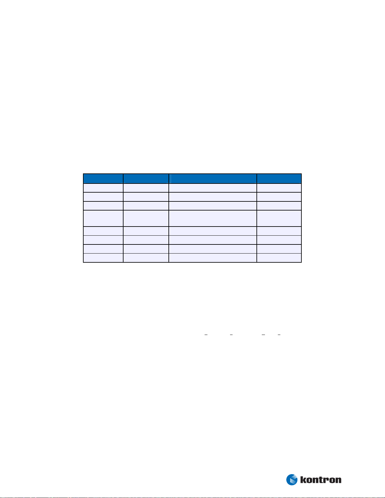
2.2 ePanel Overview
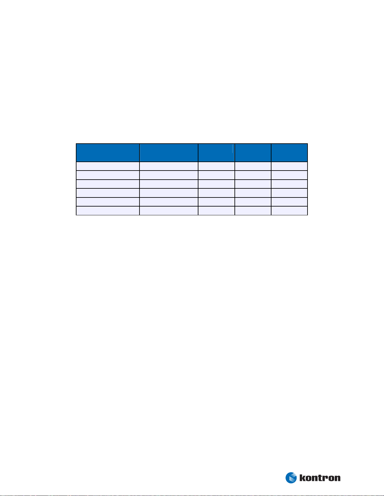
The ePanel is structured in a modular way, so we can offer you different flavours in processing power, power
consumption and I/O capabilities. Please refer to the following matrix to choose the product that suits your
needs best.
Article number CPU Touch Smart
Video In
Battery
22242
22243
22244
22245
22246
22247
CM 600 MHz
CM 1.0 GHz
PM 1.4 GHz
CM 600 MHz
CM 1.0 GHz
PM 1.4 GHz
Kontron User's Guide ePanel PM
4
Page 11

Chapter 3 Specifications
3. Specifications
3.1 Functional Specifications
Processor
• Intel® Pentium® M Processor 1.4 GHz
• Intel® Celeron® M Processor 600 MHz or 1.0 GHz
Bus
• 400 MHz CPU bus
• 200 MHz, 266 MHz or 333 MHz (only 855GME) memory bus
Chipset
• Intel® 852GM (Celeron M 600 MHz), 855GME (others)
Super I/O
• Winbond W83627 connected by LPC interface
Cache
• On-die Second level 2 MB (1.4 GHz) or 512 kB (Celeron M 600 MHz, 1.0 GHz)
Memory
• One 200-pin DDR-SODIMM
• 2.5 V unbuffered DDR-SDRAM up to 1 GB
Two Serial Ports (COM1 and COM2)
• TTL signals only
• 16550 compatible
Infrared Device Association (IrDA) interface
One Parallel Port (LPT1)
• Enhanced Parallel Port (EPP) and Extended Capabilities Port (ECP) with bi-directional
capability
Floppy
• 3.5” standard drive via Flex Foil adapter
EIDE-Interface (P-ATA)
• PCI Bus Master IDE port (up to two devices) support
• Ultra Direct Memory Access (UDMA) modes
• Programmed Input/Output (PIO) modes up to Mode 4 timing
• Multiword DMA Mode 0,1,2 with independent timing
Kontron User's Guide ePanel PM
5
Page 12

Chapter 3 Specifications
Compact Flash Socket
• Supports UDMA modes
Universal Serial Bus (USB)
• Three USB 1.1/2.0 ports (UHCI and EHCI)
• USB legacy keyboard support
• USB floppy, CD-ROM, Hard drive and Memory stick boot support
Integrated Ethernet
• Intel 82562 10/100 Mbps Fast Ethernet controller
• Integrated WfM 2.0 and IEEE 802.3 compliant 10BASE-T and 100BASE-TX compatible
PHY
Onboard Video Graphics Array (VGA)
• Integrated in Intel 852GM/855GME
• Graphics memory controller hub with Intel Extreme Graphics 2 technology
• Up to 32 MB Video RAM (UMA)
• CRT and LVDS interfaces
Audio
• Integrated in Intel 82801DB southbridge
• AC97 and Windows Sound System™ compatible
Video In
• Conexant Video Broadcast decoder CX23883
Matrix Keyboard (up to 7x8 keys)
PC Card
• 16 bit PC Card components and 32 bit Cardbus components
PS/2 Keyboard Controller
PS/2 Mouse Interface
Touch Controller
miniPCI Socket
BIOS
• PHOENIX 1MB Flash-BIOS in Firmware Hub Flash Memory
• NV-EEPROM for CMOS setup retention without battery
Watchdog Timer (WDT)
Real-Time Clock (requires external battery)
Power Management
• ACPI support
• Suspend to RAM (S3) support
Kontron User's Guide ePanel PM
6
Page 13
Chapter 3 Specifications
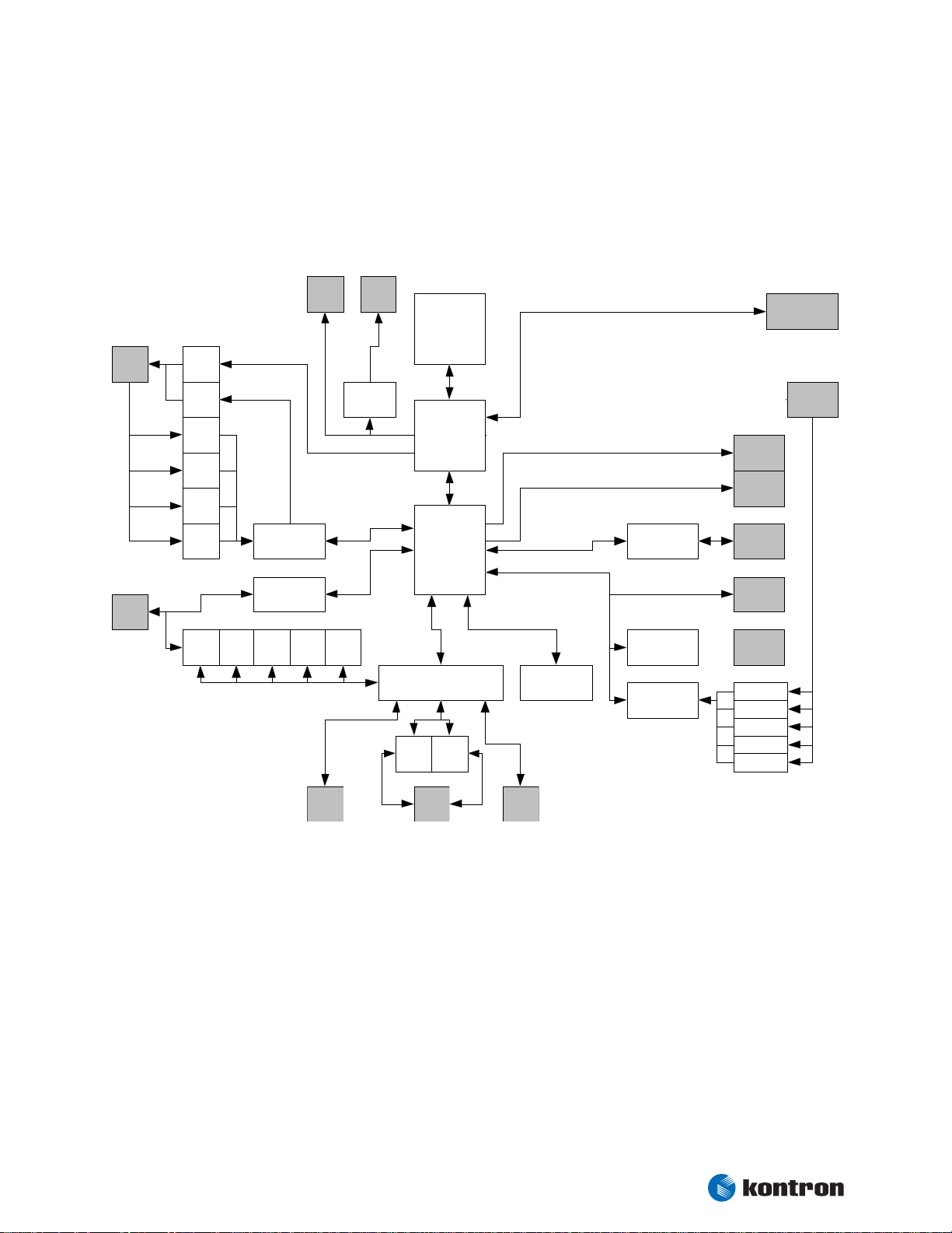
3.2 Block Diagram
ePanel PM
X506
CRT/
Audio
X504
IO
VGA
CRT
Line
out
LineIn
LineIn
CD
Aux
In
MIC
In
Key
board
AC97
VIA VT1618
Ethernet
82562ET
MouseCOM1
Phy
X1704
USB
1-3
JILI30
IRDA
X1702
FLEX32
LVDS
DS90CF364
CPU
Celeron M
Pentium M
Northbridge
82852GM
82855GME
Southbridge
82801db
LPC FW Hub
Super I/O
Winbond W 83627HG
COM2 LPT1
USB
PCI
BIOS
Video Out
Chrontel 7011
Prim. IDE
Sec. IDE
Touch
Penmount 6000
Cardbus
Bridge
TI PCI1510
Video In
Connexant
CX23883
CF Card
X1300
Sec. IDE
X501
Touch
MiniPCI
So cke t
Cardbus
So cke t
CVB S 1
CVB S 2
CVB S 3
CVB S 4
C1
RAM
X502
Video In
Video Out
X2100
Floppy
X507
Ext. IO
X503
Matrix
Kontron User's Guide ePanel PM
7
Page 14

Chapter 3 Specifications
3.3 Mechanical Specifications
3.3.1 Module Dimensions
180 mm x 140 mm ±0.2 mm
3.3.2 Height on Top
Maximum approx. 16 mm
Height is depending upon optionally CPU cooler/fan
3.3.3 Height on Bottom
Maximum approx. 6 mm
Kontron User's Guide ePanel PM
8
Page 15
Chapter 3 Specifications
3.4 Electrical Specifications
3.4.1 Supply Voltage
8 V to 28 V DC
3.4.2 Supply Voltage Ripple
100 mV peak to peak 0 - 20 MHz
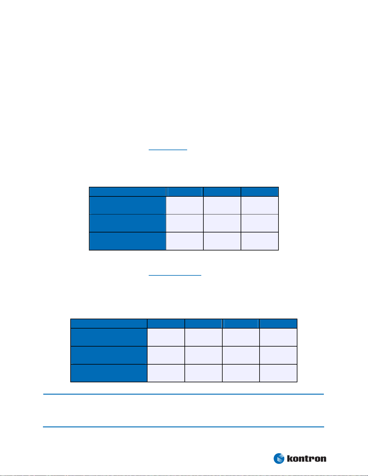
3.4.3 Supply Current (typical, DOS prompt)
Power consumption tests were executed during the DOS prompt with keyboard (PS/2), CF card and CRT
attached to it. All boards were equipped with 512 MB DDR SDRAM. Modules were tested using maximum CPU
frequency.
Normal Standby Suspend
Power Consumption
Pentium M (LV) 1.4 GHz
Power Consumption
Celeron M (ULV) 1.0 GHz
Power Consumption
Celeron M (ULV) 600 MHz
1.64 A
19.7 W
1.26 A
15.0 W
1.24 A
14.9 W
n.a n.a
n.a n.a
n.a n.a
3.4.4 Supply Current (typical, Windows XP SP2)
The tested boards were equipped with a mouse (USB), a keyboard (PS/2) and CF card. The Power consumption tests were executed during Windows XP SP2 by using the tool CPU stress. To ensure a stable dietemperature a corresponding heatsink was used to hold the temperature under the critical trip point. All
boards were equipped with 512MB DDR SDRAM. Modules were tested using maximum CPU frequency.
Normal Idle Standby S1 Suspend S3
Power Consumption
Pentium M (LV) 1.4 GHz
Power Consumption
Celeron M (ULV) 1.0 GHz
Power Consumption
Celeron M (ULV) 600 MHz
Note: It is difficult to test for all possible applications on the market. There may be an application that draws more
power from the CPU than the measured values in the table above. This should be taken into consideration if
you are on the limit of the thermal specification. If this is the case improvements to your thermal solution are
recommended.
1.98 A
23.8 W
1.30 A
15.6 W
1.26 A
15.1 W
1.15 A
13.8 W
1.00 A
12.0 W
0.96 A
11.5 W
0.83 A
10.0 W
0.80 A
9.6 W
0.78 A
9.4 W
0.06 A
0.72 W
0.06 A
0.72 W
0.06 A
0.72 W
Kontron User's Guide ePanel PM
9
Page 16

Chapter 3 Specifications
3.4.5 External RTC Battery
Voltage range: 2.0 V - 3.6 V (typ. 3.0 V)
Maximum current: 3,5 µA @ 3.0 V
English:
CAUTION ! Danger of explosion if battery is incorrectly replaced. Replace only with the same or equivalent type recom-
mended by the manufacturer. Dispose of used batteries according to the manufacturer's instructions.
Deutsch:
VORSICHT ! Explosionsgefahr bei unsachgemäßem Austausch der Batterie. Ersatz nur durch den selben oder einen vom
Hersteller empfohlenen gleichwertigen Typ. Entsorgung gebrauchter Batterien nach Angaben des Herstellers.
French:
ATTENTION ! Risque d'explosion avec l'échange inadéquat de la batterie. Remplacement seulement par le même ou un
type équivalent recommandé par le producteur. L'évacuation des batteries usagées conformément à des indications du
fabricant.
Danish:
ADVARSEL ! Lithiumbatteri – Eksplosionsfare ved fejlagtig Håndtering. Udskifting må kun ske med batteri af samme
fabrikant og type. Lever det brugte batteri tilbage til leverand∅ren.
Finnish:
VAROITUS ! Paristo voi rãjãhtãã, jos se on virheellisesti asennettu. Vaihda paristo ainoastaan laltevalmistajan
suosittelmaan tyyppiln. Havita kaytetty paristo valmistajan ohjeiden mukaisesti.
Spanish:
Precaución ! Peligro de explosión si la batería se sustituye incorrectamente. Sustituya solamente por el mismo o tipo
equivalente recomendado por el fabricante. Disponga las baterías usadas según las instrucciones del fabricante.
The battery of this product is not considered to be accessible by the end user. Therefore the safety instructions are only
given in english, german, french, danish, finish and spanish language.
If the battery of this product however is accessible by the end user, it is in the responsibility of the customer to give
the corresponding safety instructions in the required language(s).
Kontron User's Guide ePanel PM
10
Page 17

Chapter 3 Specifications
3.5 Environmental Specifications
3.5.1 Temperature
The Intel® Mobile Pentium®-M is specified for proper operation when junction temperature is within the
specified range of 0°C to 100°C.
®
The Intel
temperature are maximum 110°C.
852GM/855GME Chipset temperature and the Intel® ICH4 I/O Controller Hub 4 (82801DB) case
(1)
Note:
Operating (with appropriate airflow): 0 to +60°C
Non operating: -30 to +85°C
1 The maximum operating temperature is the maximum measurable temperature on any spot on a module’s
surface. You must maintain the temperature according to the above specification.
3.5.2 Humidity
Operating: 10% to 90% (non condensing)
Non operating: 5% to 95% (non condensing)
3.6 MTBF
The following MTBF (Mean Time Between Failure) values were calculated using a combination of manufacturer’s test data, if the data was available, and a Bellcore calculation for the remaining parts. The
Bellcore calculation used is “Method 1 Case 1”. In that particular method the components are assumed to be
operating at a 50% stress level in a 40°C ambient environment and the system is assumed to have not been
burned in. Manufacturer’s data has been used wherever possible. The manufacturer’s data, when used, is
specified at 50°C, so in that sense the following results are slightly conservative. The MTBF values shown
below are for a 40°C in an office or telecommunications environment. Higher temperatures and other
environmental stresses (extreme altitude, vibration, salt water exposure, etc.) lower MTBF values.
System MTBF (hours) : tbd
Fans usually shipped with Kontron Embedded Modules GmbH products have 50,000-hour typical operating life.
Note:
The above estimates assume no fan, but a passive heat sinking arrangement. Estimated RTC battery life (as
opposed to battery failures) is not accounted for in the above figures and need to be considered for
separately. Battery life depends on both temperature and operating conditions. When the Kontron unit has
external power; the only battery drain is from leakage paths.
Kontron User's Guide ePanel PM
11
Page 18

Chapter 4 CPU, Chipset and Super I/O
4. CPU, Chipset and Super I/O
4.1 CPU
Intel® Mobile Pentium®-M / Celeron®-M CPU features include:
Supports Intel® Architecture with Dynamic Execution
High performance, low-power core
On-die, primary 32 kbyte instruction cache and 32 kbyte write-back data cache
On-die, 1 MByte (BANIAS), 2 MByte (DOTHAN) or 512 kByte (CELERON) second level
cache with Advanced Transfer Cache Architecture
Advanced Branch Prediction and Data Prefetch Logic
Streaming SIMD Extensions 2 (SSE2)
400 MHz Source-synchronous processor system bus
Advanced Power Management features, including Enhanced Intel SpeedStep® techno-
logy (only for Pentium® M processors)
4.2 Chipset
The chipset of the ePanel PM consists of the Intel® 852GM/855GME chipset (GMCH = Graphics and Memory
Controller Hub) and the Intel
4.2.1 GMCH (852GM/855GME Chipset)
Processor/Host Bus Support
Memory System
®
82801DB ICH4 (I/O Controller Hub 4).
• Intel® Pentium® M (only 855GME) and Celleron® M processors
• Supports system bus at 400 MHz
• Supports Enhanced Intel® SpeedStep® technology
• Directly supports one DDR SDRAM channel, 64-bits wide
• Supports 200 MHz, 266 MHz and 333 MHz (only 855GME) DDR SDRAM devices with
double-sided SO-DIMMs (four rows populated).
• Supports 128-Mbit, 256-Mbit, and 512-Mbit technologies providing maximum capacity
of 1 GB with x16 devices
• All supported devices have four banks
Kontron User's Guide ePanel PM
12
Page 19

Chapter 4 CPU, Chipset and Super I/O
Internal Graphics Features
• Up to 32MB of dynamic video memory allocation
• Display image rotation
• Graphics core frequency
• Display core frequency at 133 MHz or 200 MHz (only 855GME)
• Render core frequency at 100 MHz,133 MHz or 200 MHz
• 2D graphics engine
• 3D graphics engine
• Single- or dual-channel LVDS panel support up to UXGA panel resolution with frequen-
cy range from 25 MHz to 112 MHz (single channel/dual channel)
Video Stream Decoder
• Improved hardware motion compensation for MPEG2
• Software DVD at 60 Fields/second and 30 frames/second full screen
• Support for standard definition DVD (i.e. NTSC pixel resolution of 720x480, etc.) qua-
lity encoding at low CPU utilization
Power Management
• APM 1.2 compliant power management
• ACPI 1.0b, 2.0 support
• Enhanced Intel® SpeedStep Technology support
4.2.2 ICH4 (82801DB)
PCI 2.2 Bus Interface at 33MHz
Integrated LAN Controller
• WfM 2.0 and IEEE802.3 compliant with 10/100 Mbit/s Ethernet support
USB
• Three UHCI USB 1.1 or one EHCI high speed USB 2.0 host controller(s)
Integrated IDE Controller
• Ultra ATA33/66 and PIO mode support
• One channel for up to 2 devices with independent timing
• Support of “Native Mode” register and interrupts
Interrupt Controller
• Two cascade 83C59 with 15 interrupts
• Integrated I/O APIC capability with 24 interrupts
Enhanced DMA
• Two cascaded 8237 controllers
• Supports PC/PCI DMA and LPC DMA
• Supports DMA collection buffers
Timers based on 82C54
Power Management Logic
• ACPI 2.0 compliant
• Supports PCI /PME
Low Pin Count (LPC) Interface
SM Bus 2.0 interface (System Management Bus)
Kontron User's Guide ePanel PM
13
Page 20

Chapter 4 CPU, Chipset and Super I/O
4.2.3 Super I/O
The external Super I/O WINBOND W83627 offers the following features:
Integrated keyboard controller with PS/2 mouse support
One floppy disk controller compatible with the industry standard 82077/765
Two serial ports and one multi-mode parallel port
Hardware monitor for temperature and onboard voltages
Kontron User's Guide ePanel PM
14
Page 21

Chapter 5 System Memory
5. System Memory
The ePanel PM uses only 200-pin Small Outline-Dual Inline Memory Modules (SODIMMs). One socket is
available for 2.5 Volt (power level) unbuffered DDR200, DDR266 or DDR333 (only 855GME) module of up to
1 GB.
The total amount of memory available on the DDRAM module is used for main memory and graphics memory
on the ePanel PM. The Unified Memory Architecture (UMA) manages how the system shares memory
between the graphics controller and the processor.
Kontron User's Guide ePanel PM
15
Page 22
Chapter 6 Graphics Interface
6. Graphics Interface
The uses the graphics accelerator integrated in the Intel® 852GM/855GME chipset, which delivers highperformance 2D, 3D and video capabilities. With its interface to UMA (Unified Memory Architecture) up to
32 MB of system memory are used as video memory.
The graphics accelerator supports CRT monitors and a variety of LCD panels with single or dual clock, color
depths of 18/24 bit and resolutions up to UXGA (1600x1200).
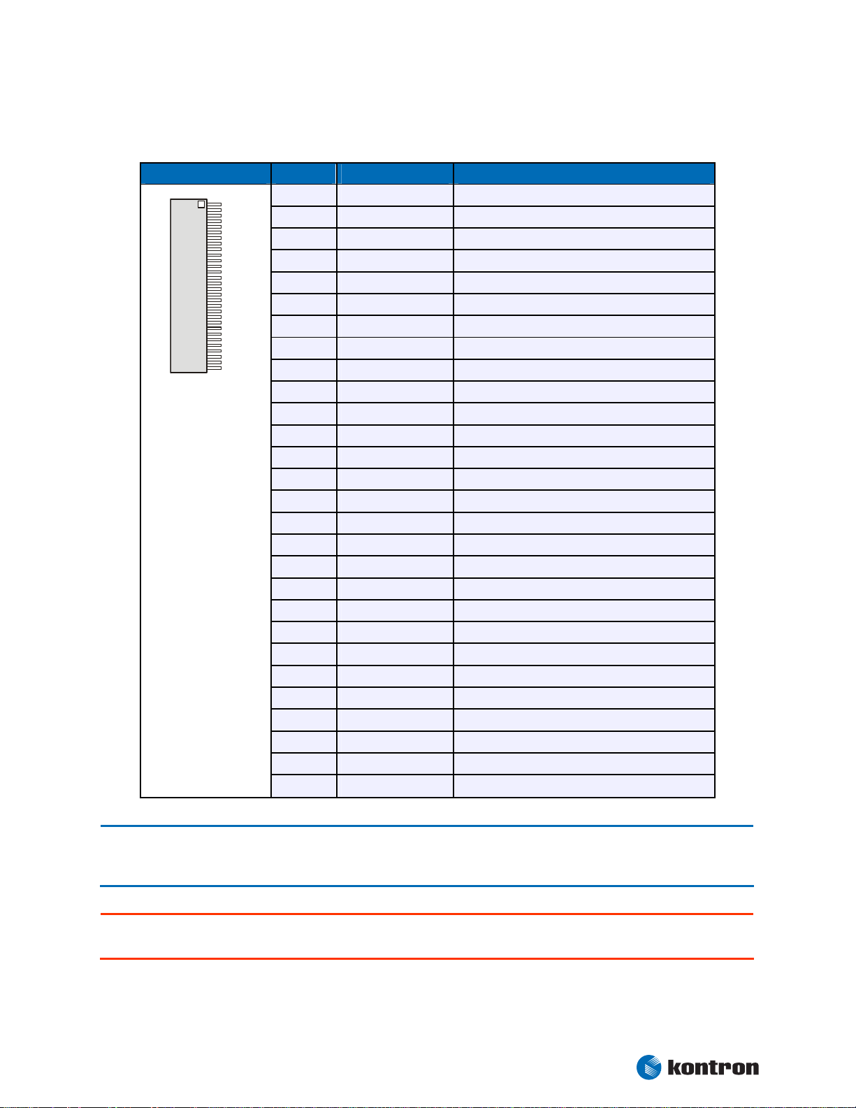
6.1 CRT Connector
The CRT monitor interface is available through the X506 connector (40 pins). A suitable adapter with cable
set is disposable from Kontron (ePanel-Adapt-V2, Part Number 22223).
Pin Signal Name Function DSUB-15
25
27
29
26, 28, 30,
33, 35, 37
31
32
34
36
GREEN
BLUE
RED
GND
DDC_SDA
DDC_SCL
VSYNC
HSYNC
Analog video green 2
Analog video blue 3
Analog video red 1
Signal ground 5, 6, 7, 8, 10
DDC data line 12
DDC clock line 15
Vertical sync 14
Horizontal sync 13
To find the location of the X506 connector on the ePanel PM board, please see the Appendix “Connector
Layout”.
6.2 LCD Panel Connectors
The LVDS interface for the LCD Panel is available through the X1704 connector (30 pins) on the top side of
the board. This connector represents the JILI interface (J
mentation of this subsystem complies with the JILI Specification of Kontron Embedded Modules GmbH. A
variety of cables for different display types are available from Kontron. Please refer to the actual cable list
on the Kontron Website for part numbers and cable names.
Another option for connecting a display to ePanel PM is a (LV)TTL compatible 18 bit RGB interface available
on X1702 (32 pins). A variety of cables for different display types are available from Kontron. Please refer to
the actual cable list on the Kontron Website for part numbers and cable names.
When using a LCD Panel, additional voltages may be required to drive the displays logic and to supply the
backlight converter. The display logic may require +5V for standard or +3.3V for low-power LCDs. Backlight
converters usually are +5V or +12V types. The onboard 3.3V and 5V circuitry of the ePanel PM and the 3.3V
or 5V panel logic voltage are share the same voltage regulators.
To find the location of the LCD Panel interface connectors on the ePanel PM board, please see the Appendix
“Connector Layout”.
UMPtec Intelligent LVDS Interface). The imple-
Kontron User's Guide ePanel PM
16
Page 23
Chapter 6 Graphics Interface
1
0
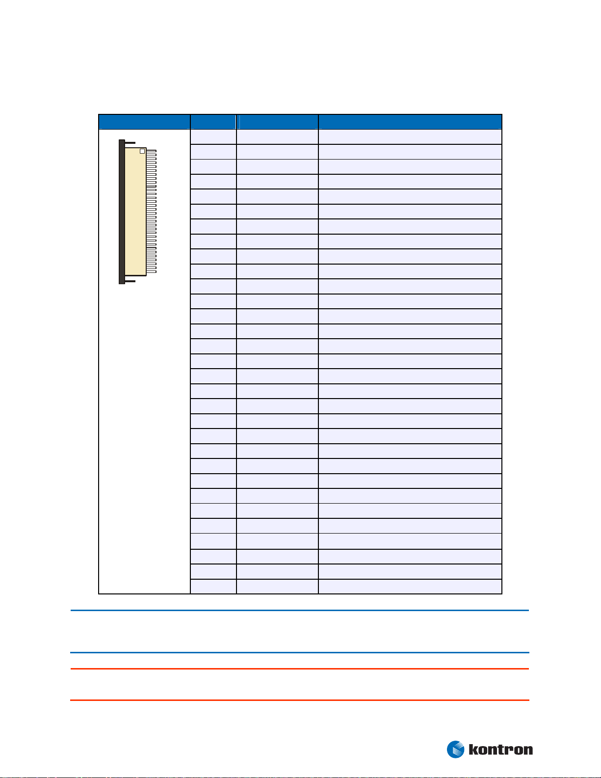
6.2.1 JILI30 Connector
Header Pin Signal Name Function
3
1
2
3
4
5
6
7
8
9
10
11
12
13
14
15
16
17
18
19
20
21
22
23
24
25
26
27
28 - 30
FTX0-
FTX0+
FTX1-
FTX1+
FTX2-
FTX2+
GND
FTXC-
FTXC+
FTX3-
FTX3+
STX0-
STX0+
GND
STX1-
STX1+
GND
STX2-
STX2+
STXC-
STXC+
STX3-
STX3+
GND
SDA
DATAENA
SCL
(1)
VCC
First channel data output 0 (negative)
First channel data output 0 (positive)
First channel data output 1 (negative)
First channel data output 1 (positive)
First channel data output 2 (negative)
First channel data output 2 (positive)
Signal ground
First channel clock output (negative)
First channel clock output (positive)
First channel data output 3 (negative)
First channel data output 3 (positive)
Second channel data output 0 (negative)
Second channel data output 0 (positive)
Signal ground
Second channel data output 1 (negative)
Second channel data output 1 (positive)
Signal ground
Second channel data output 2 (negative)
Second channel data output 2 (positive)
Second channel clock output (negative)
Second channel clock output (positive)
Second channel data output 3 (negative)
Second channel data output 3 (positive)
Signal ground
I2C data line
Data enable output
I2C clock line
Power supply
Note: 1 To protect the external power lines of peripheral devices, make sure that
- the wires have the right diameter to withstand the maximum available current.
- to enclosure of the peripheral device fulfills the fire-protecting conditions of IEC/EN 60950.
Attention: Check jumper block J1702 (Panel Power) for correct settings for your panel – not doing so might cause
permanent damage to your panel.
Kontron User's Guide ePanel PM
17
Page 24
Chapter 6 Graphics Interface
6.2.2 18 Bit Digital Connector
Header Pin Signal Name Function
1
32
1
2
3
4
5
6
7
8
9
10
11
12
13
14
15
16
17
18
19
20
21
22
23
24
25
26
27
28 - 29
30
31
32
GND
PCLK
PHS
PVS
GND
PR0
PR1
PR2
PR3
PR4
PR5
GND
PG0
PG1
PG2
PG3
PG4
PG5
GND
PB0
PB1
PB2
PB3
PB4
PB5
GND
PDE
VCC
R/L
U/D
NC
(1)
Signal ground
Data shift clock
Horizontal sync pulse
Vertical sync pulse
Signal ground
Red color data line 0
Red color data line 1
Red color data line 2
Red color data line 3
Red color data line 4
Red color data line 5
Signal ground
Green color data line 0
Green color data line 1
Green color data line 2
Green color data line 3
Green color data line 4
Green color data line 5
Signal ground
Blue color data line 0
Blue color data line 1
Blue color data line 2
Blue color data line 3
Blue color data line 4
Blue color data line 5
Signal ground
Data enable
Power supply
Rotate image left or right (option)
Rotate image up or down (option)
Reserved
Note: 1 To protect the external power lines of peripheral devices, make sure that
- the wires have the right diameter to withstand the maximum available current.
- to enclosure of the peripheral device fulfills the fire-protecting conditions of IEC/EN 60950.
Attention: Check jumper block J1702 (Panel Power) for correct settings for your panel – not doing so might cause
permanent damage to your panel.
Kontron User's Guide ePanel PM
18
Page 25
Chapter 6 Graphics Interface
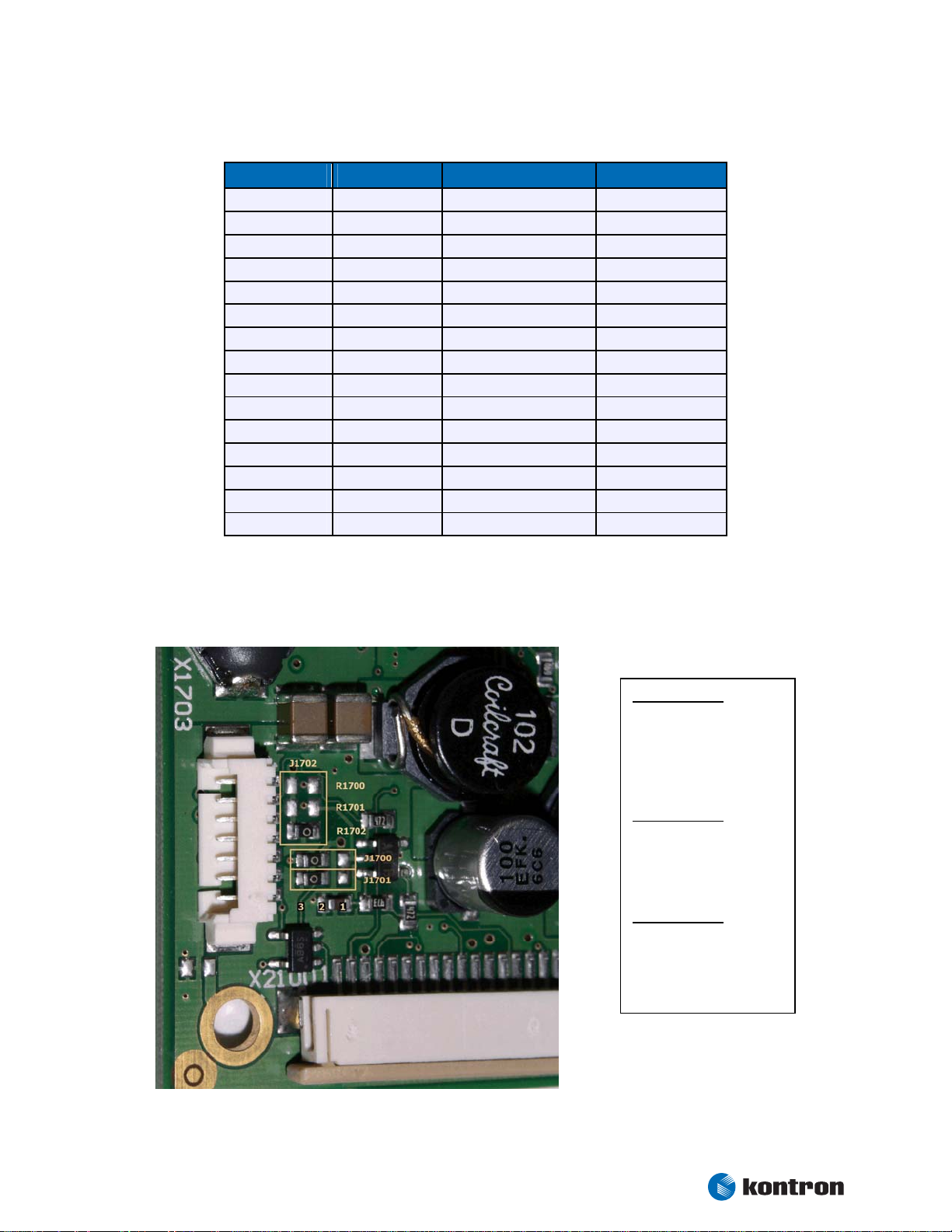
6.3 Connecting a LCD Panel
To determine whether your panel display is supported, check the Kontron Website for panel lists. We regularly update the list of panels that have been tested with the ePanel PM.
If you use one of those adapters supplied by Kontron, configuration is easy:
Check whether you have the correct adapter and cable for the panel you plan to use. Inspect
the cable for damages. Disconnect the power from your system.
Check Jumper J1702 for correct Panel voltage (R1700 = 12V R1701 = 5V R1702 = 3.3V).
Check Jumper J1700 for correct Backlight voltage (Pos. 1-2 = 5V 2-3 = 12V).
Check Jumper J1701 for correct Backlight on/off polarity (Pos. 1-2 = Low 2-3 = High).
Connect the cable to the LCD Panel connector X1702 or X1704 on the ePanel PM and connect
the other end to your display.
Connect the backlight converter.
Supply power to your system.
If no image appears on your display, connect a CRT monitor to the CRT connector.
If you still do not see improvement, consider contacting the dealer for technical support.
6.4 Available Video Modes
The following list shows the video modes supported by the graphics controller with maximum frame buffer
size. When configured for saller frame buffers and/or using a LCD panel on the JILI interface, not all of the
video modes listed below may be available. Capability depends on system configuration and on display
capabilities. Different operating systems also may not support all listed modes by the available drivers.
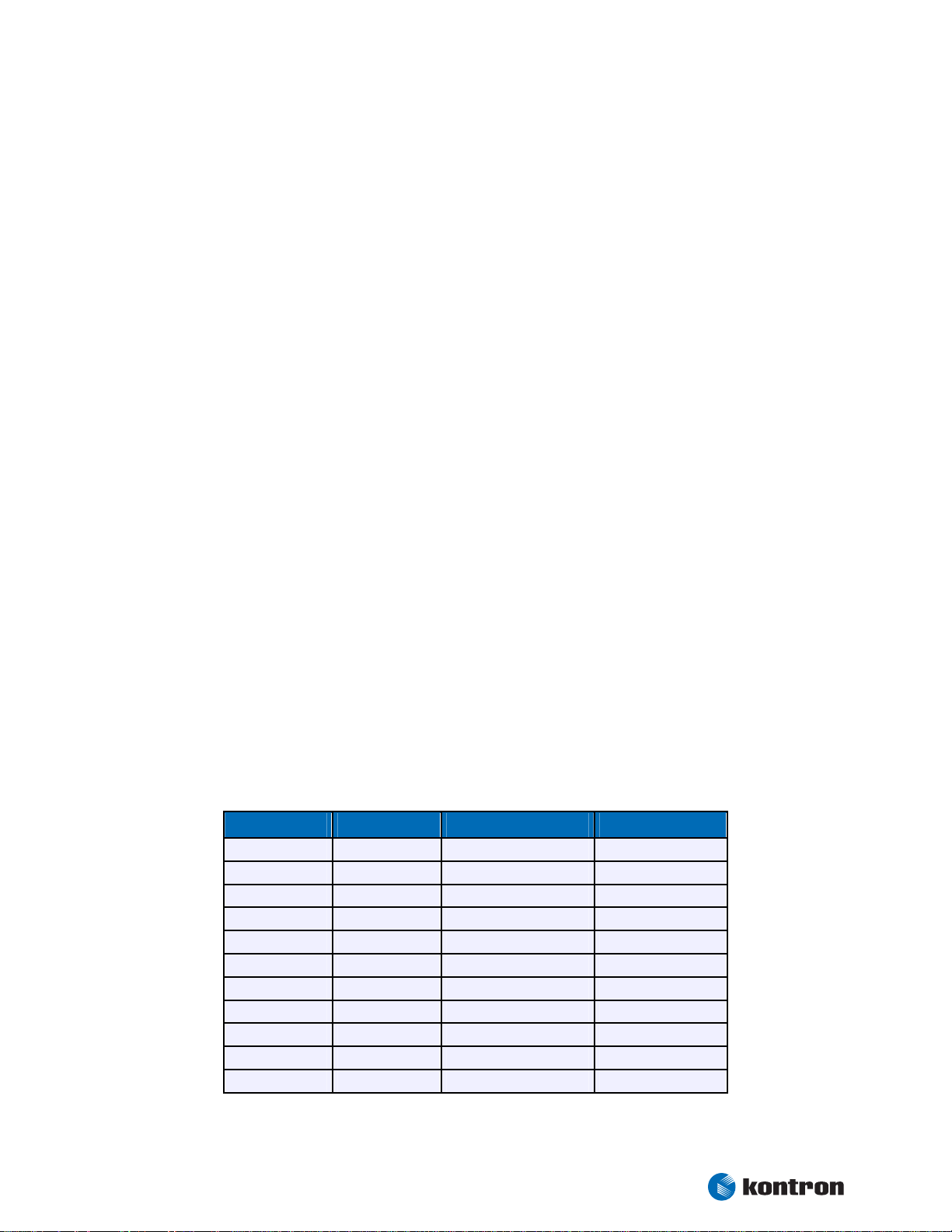
6.4.1 Standard IBM-Compatible VGA Modes
Video Mode Type Characters/Pixels Colors
00h/01h Text 40x25 16
02h/03h Text 80x25 16
04h/05h Graphics 320x200 4
06h Graphics 640x200 2
0Dh Graphics 320x200 16
0Eh Graphics 640x200 16
0Fh Graphics 640x350 Mono
10h Graphics 640x350 16
11h Graphics 640x480 2
12h Graphics 640x480 16
13h Graphics 320x200 256
Kontron User's Guide ePanel PM
19
Page 26
Chapter 6 Graphics Interface
J
6.4.2 Extended VESA VGA Modes
VESA Mode Type Pixels Colors
101h Graphics 640x480 256
103h Graphics 800x600 256
105h Graphics 1024x768 256
107h Graphics 1280x1024 256
111h Graphics 640x480 64K
112h Graphics 640x480 16M
114h Graphics 800x600 64K
115h Graphics 800x600 16M
117h Graphics 1024x768 64K
118h Graphics 1024x768 16M
11Ah Graphics 1280x1024 64K
11Bh Graphics 1280x1024 16M
13Ah Graphics 1600x1200 256
14Bh Graphics 1600x1200 64K
15Ah Graphics 1600x1200 16M
6.5 Jumper Localization
umper J1702
(Panel Voltage)
R1700 +12V
R1701 +5V
R1702 +3.3V
Jumper J1700
(Backlight Voltage)
1-2 +5V
2-3 +12V
Jumper J1701
(Backlight Polarity)
1-2 Low
2-3 High
Kontron User's Guide ePanel PM
20
Page 27
Chapter 6 Graphics Interface
7
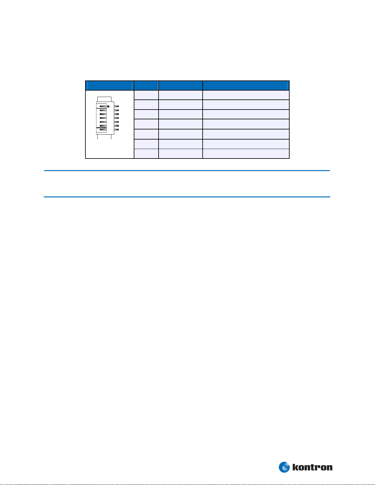
6.6 Backlight Connector
Backlight is available through the X1703 connector (7 pins).
Header Pin Signal Name Function
1
Note: 1 To protect the external power lines of peripheral devices, make sure that
- the wires have the right diameter to withstand the maximum available current.
- to enclosure of the peripheral device fulfills the fire-protecting conditions of IEC/EN 60950.
1
2
3
4
5
6
7
NC
BKLTADJ
GND
(1)
VCC
(1)
VCC
GND
BKLTON
Not connected
Brightness control (0V - 5V)
Ground
5V or 12V power supply
5V or 12V power supply
Ground
Backlight on/off
To find the location of the backlight connector on the ePanel PM board, please see the Appendix “Connector
Layout”.
Kontron User's Guide ePanel PM
21
Page 28
Chapter 7 Serial-Port Interfaces
7. Serial-Port Interfaces
Two fully functional serial ports (COMA and COMB) provide asynchronous serial communications. COMA and
COMB support RS-232 operation modes. They are 16550 high-speed UART compatible and support 16-byte
FIFO buffers for transfer rates from 50 Baud to 115.2 KBaud.
7.1 Connector
COMA is available through the X504 connector (50 pins). A suitable adapter with cable set is disposable
from Kontron (ePanel-Adapt-V2, Part Number 22223).
Pin Signal Name Function DSUB-25 DSUB-9
8
9
10
11
12
13
14
15
16
/DSR (COMA)
/DCD (COMA)
/DTR (COMA)
/RTS (COMA)
/CTS (COMA)
RXD (COMA)
TXD (COMA)
/RI (COMA)
GND
Data Set Ready 6 6
Data Carrier Detect 8 1
Data Terminal Ready 20 4
Request to Send 4 7
Clear to Send 5 8
Receive Data 3 2
Transmit Data 2 3
Ring Indicator 22 9
Signal Ground 7 5
COMB is available through the X507 connector (32 pins). A suitable adapter with cable set is disposable
from Kontron (ePanel-Adapt-V2, Part Number 22223).
Pin Signal Name Function DSUB-25 DSUB-9
3
4
5
6
7
8
9
10
11
/DSR (COMB)
/DCD (COMB)
/DTR (COMB)
/RTS (COMB)
/CTS (COMB)
RXD (COMB)
TXD (COMB)
/RI (COMB)
GND
Data Set Ready 6 6
Data Carrier Detect 8 1
Data Terminal Ready 20 4
Request to Send 4 7
Clear to Send 5 8
Receive Data 3 2
Transmit Data 2 3
Ring Indicator 22 9
Signal Ground 7 5
To find the location of the X504 and X507 connector on the ePanel PM board, please see the Appendix
“Connector Layout”.
Kontron User's Guide ePanel PM
22
Page 29
Chapter Parallel-Port Interface
8. Parallel-Port Interface
The ePanel PM incorporates a parallel port that can be set to uni-/bidirectional and supports EPP/ECP
operating modes.
8.1 Connector
The parallel port is available through the X507 connector (32 pins). A suitable adapter with cable set is
disposable from Kontron (ePanel-Adapt-V2, Part Number 22223).
Pin Signal Name Function DSUB-25
12
13
14
15
16
18
19
20
21
23
24
25
26
28
29
30
31
2,11
17,22
27,32
/AFD
/STB
/ERR
PD0
/INIT
PD1
/SLIN
PD2
PD3
PD4
PD5
PD6
PD7
/ACK
/BUSY
PE
/SLCT
GND
GND
GND
Autofeed 14
Strobe 1
Error 15
Data 0 2
Init 16
Data 1 3
Select in 17
Data 2 4
Data 3 5
Data 4 6
Data 5 7
Data 6 8
Data 7 9
Acknowledge 10
Busy 11
Paper out 12
Select out 13
Signal ground 18 - 25
Signal ground 18 - 25
Signal ground 18 - 25
To find the location of the X507 connector on the ePanel PM board, please see the Appendix “Connector
Layout”.
Kontron User's Guide ePanel PM
23
Page 30

Chapter 9 PS/2 Keyboard and Mouse Interface
9. PS/2 Keyboard and Mouse Interface
The Super I/O of the ePanel PM supports a PS/2 keyboard and mouse.
9.1 PS/2 Keyboard Connector
The keyboard interface is available through Connector X504 (50 pins). A suitable adapter with cable set is
disposable from Kontron (ePanel-Adapt-V2, Part Number 22223).
Pin Signal Name Function 5 pin DIN
(Diode)
6 pin
MiniDIN
(PS/2)
1
2
3
4
(1)
VCC
KBCLK
KBDAT
GND
+5V 5 4
Keyboard clock 1 5
Keyboard data 2 1
Ground 4 3
9.2 PS/2 Mouse Connector
The mouse interface is available through Connector X504 (50 pins). A suitable adapter with cable set is
disposable from Kontron (ePanel-Adapt-V2, Part Number 22223).
Pin Signal Name Function 6 pin
MiniDIN
(PS/2)
1
5
6
7
(1)
VCC
MSDAT
MSCLK
GND
+5V 4
Mouse data 1
Mouse clock 5
Ground 3
Note: 1 To protect the external power lines of peripheral devices, make sure that
- the wires have the right diameter to withstand the maximum available current.
- to enclosure of the peripheral device fulfills the fire-protecting conditions of IEC/EN 60950.
To find the location of the X504 connector on the ePanel PM board, please see the Appendix “Connector
Layout”.
Kontron User's Guide ePanel PM
24
Page 31

Chapter 10 USB Interface
10. USB Interface
The USB interface comes with three USB ports, which follow the UHCI/EHCI specification and are USB 2.0
compliant. You can expand the amount of USB connections by adding external hubs.
10.1 Connector
The USB ports are available through the X504 connector (50 pins). A suitable adapter with cable set is
disposable from Kontron (ePanel-Adapt-V2, Part Number 22223).
Pin Signal Name Function
22 - 24
25
26
27
28
29
30
31
32
33
34
35
(1)
VCC
PWR_ENA
/OVRCUR
GND
USB0+
USB0-
GND
USB1+
USB1-
GND
USB2+
USB2-
+5V
USB Power enable
Overcurrent detect
Signal ground
USB port 0 (positive)
USB port 0 (negative)
Signal ground
USB port 1 (positive)
USB port 1 (negative)
Signal ground
USB port 2 (positive)
USB port 2 (negative)
Note: 1 To protect the external power lines of peripheral devices, make sure that
- the wires have the right diameter to withstand the maximum available current.
- to enclosure of the peripheral device fulfills the fire-protecting conditions of IEC/EN 60950.
To find the location of the X504 connector on the ePanel PM board, please see the Appendix “Connector
Layout”.
Kontron User's Guide ePanel PM
25
Page 32

Chapter 11 Floppy-Drive Interface
11. Floppy-Drive Interface
The floppy-drive interface of the ePanel PM uses a 2.88 MB super I/O floppy-disk controller and can support
one floppy disk drive with densities that range from 360 kB to 2.88 MB. The controller is 100% IBM compatible.
11.1 Connector
The floppy disk interface is available on the flat-foil connector X2100 (26 pins). This type of connector is
often internally used in notebooks to connect a slim-line floppy drive.
Accessories are available for this interface from Kontron. To connect a standard 3.5” floppy drive, use an
adapter cable (ADA-FLOPPY-2, Part Number 96001-0000-00-0). If you have a slim-line 3.5” floppy drive, you
may need a flat foil cable (KAB-FLOPPY/ MOPS-1, Part Number 96019-0000-00-0). It also is possible to get a
slim line 3.5” floppy drive with cable from Kontron (FLOPPY-MOPS-1, Part Number 96010-0000-00-0).
Header Pin Signal Name Function Pin Signal Name Function
1
1
3
5
7
9
11
13
15
17
19
21
23
25
VCC
VCC
VCC
GND
GND
GND
GND
GND
GND
NC
NC
NC
NC
(1)
(1)
(1)
+5V 2
+5V 4
+5V 6
Not connected 8
Not connected 10
Not connected 12
Not connected 14
Ground 16
Ground 18
Ground 20
Ground 22
Ground 24
Ground 26
/IDX
/DR0
/DSKCHG
NC
/MTR0
/FDIR
/STEP
/WDATA
/WGATE
/TRK0
/WRTPRT
/RDATA
/HDSEL
Index
Drive Select 0
Disk Change
Not connected
Motor on 0
Direction Select
Step
Write Data
Write Gate
Track 00
Write Protect
Read Data
Side One Select
Note: 1 To protect the external power lines of peripheral devices, make sure that
- the wires have the right diameter to withstand the maximum available current.
- to enclosure of the peripheral device fulfills the fire-protecting conditions of IEC/EN 60950.
To find the location of floppy-drive interface on the ePanel PM board, please see the Appendix "Connector
Layout".
Kontron User's Guide ePanel PM
26
Page 33

Chapter 12 EIDE Interface
12. EIDE Interface
The ePanel PM features one EIDE interface (Secondary channel, UDMA33/66 mode) that can drive two hard
disks. When two devices share a single adapter, they are connected in a master/slave, daisy-chain configuration. If only one drive is in the system, you must set it as the master.
12.1 Connector
The EIDE interface is available through Connector X1300 (44 pins). This interface is designed in 2mm grid
for optimal connectivity to a 2.5” hard disk.
You can use two cables to directly connect a hard disk in a 2.5” form factor (KAB-IDE-2MM, Part Number
96021-0000-00-0) or a 3.5” form factor (KAB-IDE-25, Part Number 96020-0000-00-0).
Header Pin Signal Name Function Pin Signal Name Function
1
3
5
7
9
11
13
15
17
19
21
23
25
27
29
31
33
35
37
39
41
43
/RESET
HDD7
HDD6
HDD5
HDD4
HDD3
HDD2
HDD1
HDD0
GND
DRQ
/IOW
/IOR
IOCHRDY
/ACK
IRQ
SA1
SA0
/CS1
NC
(1)
VCC
GND
Reset 2
Data 7 4
Data 6 6
Data 5 8
Data 4 10
Data 3 12
Data 2 14
Data 1 16
Data 0 18
Signal ground 20
IDE DMA request 22
I/O write 24
I/O read 26
I/O channel ready 28
Acknowledge 30
Interrupt 32
Addr 1 34
Addr 0 36
Chip select 1 38
Not connected 40
+5V 42
Signal ground 44
GND
HDD8
HDD9
HDD10
HDD11
HDD12
HDD13
HDD14
HDD15
Key (NC)
GND
GND
GND
(2)
CSEL
GND
NC
/PDIAG
SA2
/CS3
GND
(1)
VCC
NC
Signal ground
Data 8
Data 9
Data 10
Data 11
Data 12
Data 13
Data 14
Data 15
Key pin
Signal ground
Signal ground
Signal ground
Cable select
Signal ground
Not connected
Passed diag
Addr 2
Chip select 3
Signal ground
+5V
Not connected
Kontron User's Guide ePanel PM
27
Page 34

Chapter 12 EIDE Interface
Note: 1 To protect the external power lines of peripheral devices, make sure that
- the wires have the right diameter to withstand the maximum available current.
- to enclosure of the peripheral device fulfills the fire-protecting conditions of IEC/EN 60950.
2 Pin 28 is connected with 470
Ω
to Ground for Cable Select IDE devices.
To find the location of EIDE interface on the ePanel PM board, please see the Appendix “Connector Layout”.
12.2 Compact Flash Card Interface
The primary IDE channel is realized as a CF-Card interface, also capable of UDMA.
Warning: Inserting or removing the Compact Flash Card while in operation can cause serious damage and must be
avoided.
12.3 Limitations
By default only UDMA2 is supported (even a 80pin cable doesn't have an effect). For higher UDMA modes
the “User“ setting (menu “Main / Primary (Slave) / Type“) in the setup have to be modified.
Kontron User's Guide ePanel PM
28
Page 35

Chapter 13 Ethernet Controller
13. Ethernet Controller
The Ethernet interface of the ePanel PM uses the ICH4 integrated 32-bit PCI LAN controller in combination
with the Intel® 82562 platform LAN connect device. The network controllers support 10/100 Base-T interfaces. The devices auto-negotiate the use of a 10 Mbit/sec or 100 Mbit/sec connection.
13.1 Connector
The Ethernet interface is available through Connector X504 (50 pins). A suitable adapter with cable set is
disposable from Kontron (ePanel-Adapt-V2, Part Number 22223).
Pin Signal Name Function
37
38
39
40
41
42
43
44
45
RXD+
RXD-
GND
TXD+
TXDGND
LILED
SPEEDLED
ACTLED
10/100 BASE-T receive
10/100 BASE-T receive
Signal ground
10/100 BASE-T transmit
10/100 BASE-T transmit
Signal ground
Valid LAN link LED
LAN speed LED
LAN activity LED
Note: TXD+, TXD- differential-output pair drives 10 and 100 Mb/s Manchester-encoded data to 10/100 BASE-T trans-
mit lines. RXD+, RXD- differential input pair receives 10 and 100 Mb/s Manchester-encoded data from 10/100
BASE-T receive lines.
To find the location of the X504 connector on the ePanel PM board, please see the Appendix “Connector
Layout”.
Kontron User's Guide ePanel PM
29
Page 36

Chapter 14 Touch Interface
14. Touch Interface
The ePanel PM touch controller supports 4-wire, 5-wire and 8-wire touch panels. The built-in 10 bit A/D
converter transmits the sampled data over an USB 1.1 interface to the host.
14.1 Connector
The touch interface is available through the X501 connector (16 pins).
Header Pin Signal Name Function
1
2
3
4
5
6
7
8
9
10
11
12
13
14
15
16
GND
YB / UL
SYB
GND
YT / UR
SYT
GND
XL / LL
SXL
GND
XR / LR
SXR
GND
NC
SENSE
GND
Signal ground
Bottom / Upper left
Sense bottom
Signal ground
Top / Upper right
Sense top
Signal ground
Left / Lower left
Sense left
Signal ground
Right / Lower right
Sense right
Signal ground
Not connected
Sense (5-wire)
Signal ground
To find the location of the touch interface on the ePanel PM board, please see the Appendix “Connector
Layout”.
14.2 4-Wire / 8-Wire Touch
The following table shows the pin assignment for 4-wire / 8-wire touch panels.
Signal Name 4-Wire 8-Wire
Bottom (YB) connect Pin 2 and 3 Pin 2
Sense Bottom (SYB) Pin 3
Top (YT) connect Pin 5 and 6 Pin 5
Sense Top (SYT) Pin 6
Left (XL) connect Pin 8 and 9 Pin 8
Sense Left (SXL) Pin 9
Right (XR) connect Pin 11 and 12 Pin 11
Sense Right (SXR) Pin 12
Kontron User's Guide ePanel PM
30
Page 37

Chapter 14 Touch Interface
14.3 5-Wire Touch
The following table shows the pin assignment for a 5-wire touch panel.
Signal Name 5-Wire
Upper Left (UL) Pin 2
Upper Right (UR) Pin 5
Lower Left (LL) Pin 8
Lower Right (LR) Pin 11
SENSE Pin 15
Kontron User's Guide ePanel PM
31
Page 38

Chapter 15 Matrix Keyboard Interface
15. Matrix Keyboard Interface
The ePanel PM supports a matrix keyboard of up to 7x8 keys. The necessary decoupling diodes are not
present on the ePanel PM and must be placed externally.
15.1 Connector
The matrix keyboard is available through the X503 connector (20 pins).
Header Pin Signal Name Function
1
2
3
4
5
6
7
8
9
10
11
12
13
14
15
16
17
18
19
20
GND
(1)
VCC
MAT_OUT0
MAT_OUT1
MAT_OUT2
MAT_OUT3
MAT_OUT4
MAT_OUT5
MAT_OUT6
MAT_OUT7
GND
(1)
VCC
MAT_IN0
MAT_IN1
MAT_IN2
MAT_IN3
MAT_IN4
MAT_IN5
MAT_IN6
NC
Signal ground
+5V
Row 0
Row 1
Row 2
Row 3
Row 4
Row 5
Row 6
Row 7
Signal ground
+5V
Column 0
Column 1
Column 2
Column 3
Column 4
Column 5
Column 6
Reserved
Note: 1 To protect the external power lines of peripheral devices, make sure that
- the wires have the right diameter to withstand the maximum available current.
- to enclosure of the peripheral device fulfills the fire-protecting conditions of IEC/EN 60950.
To find the location of the matrix keyboard interface on the ePanel PM board, please see the Appendix
“Connector Layout”.
Kontron User's Guide ePanel PM
32
Page 39

Chapter 16 Infrared Interface
16. Infrared Interface
The Super I/O of the ePanel PM incorporates a infrared interface. IrDA 1.0 SIR protocol and ASK-IR are
supported.
16.1 Connector
The infrared interface is available through Connector X504 (50 pins).
Pin Signal Name Function
17
18
19
20
IRRX
IRTX
GND
VCC
(1)
Note: 1 To protect the external power lines of peripheral devices, make sure that
- the wires have the right diameter to withstand the maximum available current.
- to enclosure of the peripheral device fulfills the fire-protecting conditions of IEC/EN 60950.
Infrared receive
Infrared transmit
Signal ground
+5V
To find the location of the X504 connector on the ePanel PM board, please see the Appendix “Connector
Layout”.
Kontron User's Guide ePanel PM
33
Page 40

Chapter 17 VideoIn Interface
17. VideoIn Interface
The ePanel PM features a 10 bit NTSC/PAL/SECAM composite and S-Video decoder. The multiplexer can
select between four composite inputs, or between three composite inputs and one S-Video input.
17.1 Connector
The VideoIn interface is available through Connector X502 (45 pins). A suitable adapter with cable set is
disposable from Kontron (ePanel-Adapt/TV, Part Number 22224).
Header Pin Signal
Name
1
45
1
3
5
7
9
11
13
15
17
19
21
23
25
27
29
31
33
35
37
39
41
43 - 44
GND
GND
GND
GND
GND
GND
GND
GND
GND
GND
GND
GND
GND
GND
GND
GND
GND
VCC
NC
NC
NC
NC
(1)
Function Pin Signal
Name
Signal ground 2
Signal ground 4
Signal ground 6
Signal ground 8
Signal ground 10
Signal ground 12
Signal ground 14
Signal ground 16
Signal ground 18
Signal ground 20
Signal ground 22
Signal ground 24
Signal ground 26
Signal ground 28
Signal ground 30
Signal ground 32
Signal ground 34
Not connected 36
Not connected 38
Not connected 40
Not connected 42
+3.3V 45
CVBS_IN0
CVBS_IN1
CVBS_IN2
SVID_C
CVBS_IN3
SVID_L
GND
GND
GND
GND
GND
VCC
NC
NC
NC
NC
NC
NC
NC
NC
NC
NC
NC
(1)
S-Video chroma
(2)
Function
Composite 0
Composite 1
Composite 2
Composite 3
S-Video luma
Not connected
Not connected
Not connected
Not connected
Not connected
Not connected
Not connected
Not connected
Not connected
Not connected
Not connected
Signal ground
Signal ground
Signal ground
Signal ground
Signal ground
+5V
Note: 1 To protect the external power lines of peripheral devices, make sure that
- the wires have the right diameter to withstand the maximum available current.
- to enclosure of the peripheral device fulfills the fire-protecting conditions of IEC/EN 60950.
2 The luma component is fed through the composite multiplexer, any composite input can be used.
Kontron User's Guide ePanel PM
34
Page 41

Chapter 18 Audio Interface
18. Audio Interface
The ePanel PM supports an AC'97 V2.3 audio codec with 18 bit resolution and sampling rates up to 96 kHz.
The interface includes for example LINE OUT, LINE IN and MICROPHONE IN.
18.1 Connector
The audio interface is available through Connector X506 (40 pins). A suitable adapter with cable set is
disposable from Kontron (ePanel-Adapt-V2, Part Number 22223).
Pin Signal Name Function
1
2
3
4
5
6
7
8
9
10
11
12
13
14
15
16
17
18
19
GND
AUX_L
GND
AUX_R
GND
LINEIN_L
GND
LINEIN_R
GND
CD_L
GND
CD_R
GND
MIC
GND
LINEOUT_L
GND
LINEOUT_R
GND
Signal ground
Auxiliary input left
Signal ground
Auxiliary input right
Signal ground
Line input left
Signal ground
Line input right
Signal ground
CD input left
Signal ground
CD input right
Signal ground
Microphone input
Signal ground
Line out left
Signal ground
Line out right
Signal ground
To find the location of the X506 connector on the ePanel PM board, please see the Appendix “Connector
Layout”.
Kontron User's Guide ePanel PM
35
Page 42

Chapter 19/20 PC Card Interface/MiniPCI Interface
19. PC Card Interface
The adapter allows the use of 16 bit PC Card components (Type I and II) and 32 bit Cardbus components.
These are PCI components, so there are no restrictions. The situation is different for PC Card components,
which requires often a legacy interrupt. Please ensure via System Bios that at least one legacy IRQ is
available.
20. MiniPCI Interface
On the underside of the ePanel PM is a 124 pin miniPCI connector (Type III), as is commonly used in laptop
computers. Some optional signals, however, are not available among others: /MPCIACT, RING, TIP and LED
signals. Support of 66 MHz operation is not specified.
Kontron User's Guide ePanel PM
36
Page 43

Chapter 21 Power Supply
21. Power Supply
After switching on the supply voltage the board is then immediately ready to operate, though only on
standby power. When the power button is pressed the remaining supply voltages are connected and the
board begins to work.
21.1 Power Connector
The power connector is available as X2001 (4 pins).
Header Pin Signal Name Function
4
1
1
2
3
4
DC_IN
DC_IN
GND
GND
(1)
(1)
Power supply (+8V to +28V)
Power supply (+8V to +28V)
Ground
Ground
Note: 1 To protect the external power lines of peripheral devices, make sure that
- the wires have the right diameter to withstand the maximum available current.
- to enclosure of the peripheral device fulfills the fire-protecting conditions of IEC/EN 60950.
To find the location of the power connector on the ePanel PM board, please see the Appendix “Connector
Layout”.
21.2 Power Pins
Every power pin on the power connector is limited to a maximum current and the following limitations
apply:
Power Number of Pins Max. Current
DC_IN 2 2A (AWG26)
21.3 Power / Reset Button
Both buttons are available through Connector X504 (50 pins). A suitable adapter with cable set is disposable from Kontron (ePanel-Adapt-V2, Part Number 22223).
Pin Signal Name Function
47
48
49
50
Kontron User's Guide ePanel PM
PWR_LED
RST_BTN
PWR_BTN
GND
Power LED (low active)
Reset button (low active)
Power button (low active)
Signal ground
37
Page 44
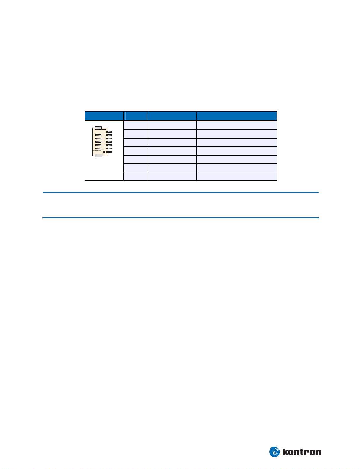
Chapter 21 Power Supply
7
21.4 Battery Connector
If an optional battery (accumulator) is employed, the power adapter voltage should be a few volts above the
battery voltage. A 12V battery can't be loaded with a 12V power voltage, for this, at least 15V would be
required.
The battery connector is available as X2000 (7 pins).
Header Pin Signal Name Function
1
2
DC_BAT
DC_BAT
3
1
4
5
6
7
SCL
SDA
NC
GND
GND
(1)
(1)
Battery supply
Battery supply
SMBus clock line
SMBus data line
Not connected
Ground
Ground
Note: 1 To protect the external power lines of peripheral devices, make sure that
- the wires have the right diameter to withstand the maximum available current.
- to enclosure of the peripheral device fulfills the fire-protecting conditions of IEC/EN 60950.
To find the location of the battery connector on the ePanel PM board, please see the Appendix “Connector
Layout”.
Kontron User's Guide ePanel PM
38
Page 45

Chapter 22 Fan Interface
1
22. Fan Interface
If a fan has to be changed or added, use this interface to connect a fan to cool off the CPU. The onboard
system controller monitors the fan speed. The connector supports 5V fans only.
A three pin fan includes a pulse output (Sense), which allows the control of fan speed. Only frequencies
equal to 2x rotor speed guarantee the correct function.
22.1 Connector
The fan interface is available through Connector X2101 (3 pins).
Header Pin Signal Name Function
1
2
3
SENSE
(1)
VCC
GND
Speed Monitoring
+5V
Signal ground
Note: 1 To protect the external power lines of peripheral devices, make sure that
- the wires have the right diameter to withstand the maximum available current.
- to enclosure of the peripheral device fulfills the fire-protecting conditions of IEC/EN 60950.
To find the location of the fan interface on the ePanel PM board, please see the Appendix “Connector Layout”.
Kontron User's Guide ePanel PM
39
Page 46

Chapter 23 Watchdog Timer
23. Watchdog Timer
The watchdog timer (WDT) is integrated in the Winbond W83627 controller of the ePanel PM and can issue a
reset to the system. The watchdog timer circuit has to be triggered within a specified time by the application
software. If the watchdog timer is not triggered because proper software execution fails or a hardware
malfunction occurs, it resets the system.
23.1 Configuration
You can set the watchdog timer to Disabled, Reset or NMI. You can specify the delay time and the time-out
(trigger period) from 1 second to 30 minutes. The delay time is the time after first initialization before the
trigger period starts. The timeout is the time the watchdog timer has to be triggered within. You can make
the initialization settings in the BIOS setup.
23.2 Programming
23.2.1 Initialization
You can initialize the watchdog timer from the BIOS setup. You also can set up the initialization from the
application software with help of the JIDA (Jumptec Intelligent Device Architecture) programmer’s interface.
23.2.2 Trigger
The watchdog needs to be triggered out of the application software within a specified timeout period. You
can only do this in the application software by using low-level programming or with help of the JIDA programmer’s interface.
For information about the JIDA programmer’s interface refer to the JIDA software packages on the Kontron
Website.
Kontron User's Guide ePanel PM
40
Page 47

Chapter 24 Hardware Monitor
24. Hardware Monitor
The Winbond W83627 controller monitors several critical hardware parameters of the system, including
power-supply voltages, fan speed and CPU temperature, which are very important for a high-end computer
system to remain stable and function properly.
The following parameters are monitored:
+3.3V from onboard DC/DC
CPU core voltage
+5V standby voltage
Battery voltage
CPU temperature with on-die diode
CPU fan speed
24.1 Configuration
You can use the Hardware Monitor submenu in the BIOS Setup Utility to obtain information on voltages, fan
speed and to check the temperature of the CPU die.
To monitor the parameters of this feature from your operating system, Kontron recommends that you use
the 32-bit protected mode J
demo application for Windows 95/98/ME/NT/2000/XP, which is available on the KONTRON Website
UMPtec’s Intelligent Device Architecture driver (JIDA 32) with the test and
Kontron User's Guide ePanel PM
41
Page 48

Chapter 25/26 Thermal Management/Power Management
25. Thermal Management
The Thermal Management feature of the ePanel PM helps control the processor’s temperature by activating
the automatic thermal throttling after the processor silicon reaches a certain temperature. This feature can
be enabled and configured in the BIOS Setup utility. You can specify the temperature level when throttling
starts, define a hysteresis value to get back to 100% CPU performance, and specify the percentage for CPU
performance in throttling mode. Automatic thermal throttling mode does not require additional hardware,
software drivers, or interrupt-handling routines.
Additionally the processor of the ePanel PM protects itself from catastrophic overheating by use of an
internal thermal sensor. This sensor is set well above the normal operating temperature to ensure that there
are no false trips. The processor will stop all execution when the junction temperature exceeds the sensor
setting. This is signaled to the system by the THERMTRIP# (Thermal Trip) pin. Once activated, the signal
remains latched, and the processor stopped, until RESET# goes active. There is no hysteresis built into the
thermal sensor itself; as long as the die temperature drops below the trip level, a RESET# pulse will reset the
processor and execution will continue. If the temperature has not dropped below the trip level, the
processor will continue to drive THERMTRIP# and remain stopped. The temperature level for catastrophic
overheating being activated is 135°C.
26. Power Management
For possible wakeup events from the different power states, please see below table.
Power State Wake-Up Events from
S1
S3
S5
PS/2 Keyboard and Mouse, USB Devices
LAN, Power Button
LAN, Power Button
Kontron User's Guide ePanel PM
42
Page 49

Chapter 27 Onboard Device Configuration
27. Onboard Device Configuration
Many of the onboard devices offer several configuration settings in the System BIOS setup. Refer to chapter
SETUP GUIDE for more configuration information.
Onboard Device see Main Menu / Sub Menu
Graphics Interface
CPU/Memory Interface
Serial Port Interfaces
Parallel Port Interface
Keyboard Interface
PS/2 Mouse Interface
USB Interface
Network Interface
Audio Interface
PC Card Interface
Advanced / Advanced Chipset Control / Graphics Memory
Advanced / Display Control / Display Mode
Advanced / Display Control / Flat Panel Type
Advanced / Display Control / Flat Panel Scaling
Advanced / Display Control / Flat Panel Backlight
Advanced / Advanced Chipset Control / Max. supported Mem. Freq.
Advanced / Memory Cache / Memory Cache
Advanced / Memory Cache / Cache System BIOS Area
Advanced / Memory Cache / Cache Video BIOS Area
Advanced / Memory Cache / Cache Base 0-512k
Advanced / Memory Cache / Cache Base 512k-640k
Advanced / Memory Cache / Cache Extended Memory Area
Advanced / Memory Cache / Cache D0000-D3FFF
Advanced / Memory Cache / Cache D4000-D7FFF
Advanced / Memory Cache / Cache D8000-DBFFF
Advanced / Memory Cache / Cache DC000-DFFFF
Advanced / IO Device Configuration / SIO Options / Serial Port A
Advanced / IO Device Configuration / SIO Options / Serial Port B
Advanced / IO Device Configuration / SIO Options / Onboard LPT
Advanced / Keyboard Features / NumLock
Advanced / Keyboard Features / Key Click
Advanced / Keyboard Features / Keyboard Auto-Repeat Rate
Advanced / Keyboard Features / Keyboard Auto-Repeat Delay
Advanced / Miscellaneous / PS2 Mouse
Advanced / PCI-PNP Configuration / Onboard USB EHCI IRQ Line
Advanced / IO Device Configuration / USB Options / USB UHCI Contr. 1
Advanced / IO Device Configuration / USB Options / USB UHCI Contr. 2
Advanced / IO Device Configuration / USB Options / USB Touch Controller
Advanced / IO Device Configuration / USB Options / USB EHCI Controller
Advanced / IO Device Configuration / USB Options / Legacy USB Support
Advanced / IO Device Configuration / USB Options / EHCI Legacy Support
Advanced / PCI-PNP Configuration / Onboard LAN IRQ Line
Advanced / IO Device Configuration / LAN Options / Onboard LAN Controller
Advanced / IO Device Configuration / LAN Options / Onboard LAN PXE ROM
Advanced / IO Device Configuration / LAN Options / Enable WOL
Advanced / IO Device Configuration / AC97 Audio Controller
Advanced / PCI-PNP Configuration / CardBus Controller
Kontron User's Guide ePanel PM
43
Page 50

Chapter 27 Onboard Device Configuration
IDE Interface
Floppy Interface
SMBus Interface
Watchdog Timer
miniPCI Slot
BIOS Extensions
(Miscellaneous)
Main / Compact Flash, Secondary Master (Slave) / Type
Main / Compact Flash, Secondary Master (Slave) / Multi-Sector Transfers
Main / Compact Flash, Secondary Master (Slave) / LBA Mode Control
Main / Compact Flash, Secondary Master (Slave) / 32 Bit IO
Main / Compact Flash, Secondary Master (Slave) / Transfer Mode
Main / Compact Flash, Secondary Master (Slave) / Ultra DMA Mode
Main / SMART Device Monitoring
Main / Hard Disk Pre-Delay
Advanced / IO Device Configuration / Local Bus IDE Adapter
Advanced / Miscellaneous / Large Disk Access Mode
Main / Legacy Diskette A:
Advanced / IO Device Configuration / SIO Options / Onboard FDC
Advanced / Miscellaneous / Floppy Check
Advanced / PCI-PNP Configuration / Assign IRQ to SMB
Advanced / Watchdog Settings / Mode
Advanced / Watchdog Settings / Timeout
Advanced / Watchdog Settings / Delay
Advanced / PCI-PNP Conf. / PCI Device, miniPCI Slot / Enable Slot
Advanced / PCI-PNP Conf. / PCI Device, miniPCI Slot / Option ROM Scan
Advanced / PCI-PNP Conf. / PCI Device, miniPCI Slot / Enable Master
Advanced / PCI-PNP Conf. / PCI Device, miniPCI Slot / Latency Timer
Advanced / PCI-PNP Configuration / miniPCI Slot IRQ Line
Advanced / Advanced Chipset Control / Serial Interrupt Mode
Advanced / PCI-PNP Configuration / PNP OS Installed
Advanced / PCI-PNP Configuration / Reset Configuration Data
Advanced / PCI-PNP Configuration / Secured Setup Configuration
Advanced / Keyboard Features / PS2 Scanner Workaround
Advanced / Miscellaneous / Summary Screen
Advanced / Miscellaneous / Quickboot Mode
Advanced / Miscellaneous / Extended Memory Testing
Advanced / Miscellaneous / Dark Boot
Advanced / Miscellaneous / Halt on Errors
Advanced / Miscellaneous / Spread Spectrum
Kontron User's Guide ePanel PM
44
Page 51

Chapter 28 Setup Guide
28. Setup Guide
The PHOENIX BIOS Setup Utility changes system behavior by modifying the BIOS configuration. The setup
program uses a number of menus to make changes and turn features on or off.
Whenever you contact technical support about BIOS issues, providing a BIOS version <ePPMR???> is especially helpful.
28.1 Start PHOENIX BIOS Setup Utility
To start the PHOENIX BIOS Setup Utility, press the <F2> key when the following string appears during boot
up.
Press <F2> to enter Setup
The Main Menu then appears with the serial number. The board’s serial number has valuable information for
technical support.
28.2 General Information
The Setup Screen is composed of several sections:
Setup Screen Location Function
Menu Bar Top Lists and selects all top-level menus.
Legend Bar Bottom Lists setup navigation keys.
Item Specific Help Window Right Help for selected item.
Menu Bar
The menu bar at the top of the window lists different menus. Use the left/right/up/down arrow keys to make
a selection.
Legend Bar
Use the keys listed in the legend bar on the bottom to make your selections or exit the current menu.
Note: In the Option column, bold shows default settings.
Kontron User's Guide ePanel PM
45
Page 52

Chapter 28 Setup Guide
28.3 Info Menu
Feature Description
Bios Version Shows the actual BIOS version
BIOS Date Shows the BIOS production date
Board Name Shows the KONTRON specific board name (JIDA entry)
Board Class Shows the KONTRON specific board class (JIDA entry)
Serial Number Shows the KONTRON specific serial number (JIDA entry)
Manufacturing Date Shows the KONTRON specific manufacturing date (JIDA entry)
Hardware Revision Shows the KONTRON specific hardware revision (JIDA entry)
Boot Counter Shows the actual boot counter
CPU Type Shows the CPU type
CPU Speed Shows the CPU speed
System Memory Displays amount of conventional memory detected during boot-
up
Extended Memory Displays amount of extended memory detected during boot-up
Extended memory = capacity of memory module – selected frame
buffer memory size
Shadow RAM Displays shadow part of BIOS components (including D-seg-
ment)
28.4 Main Menu
Feature Option Description
System Time HH:MM:SS Sets system time
System Date MM/DD/YYYY Sets system date
Legacy Diskette A:
8Compact Flash
8Secondary Master
8Secondary Slave
SMART Device
Monitoring
Hard Disk Pre-Delay
Disabled, 360 kB, 1.2 MB
Sets type of floppy disk drive
720 kB, 1.44/1.25 MB, 2.88 MB
Autodetected drive Displays result of CF autotyping
Autodetected drive Displays result of IDE autotyping
Autodetected drive Displays result of IDE autotyping
Disabled
Enabled
Turns on Self-Monitoring Analysis-Reporting Technology which monitors the
condition of the hard drive
Disabled, 3 Sec., 6 Sec., 9 Sec
12 Sec., 15 Sec., 21 Sec., 30 Sec.
Adds a delay before the first access of a
IDE drive by the BIOS
Kontron User's Guide ePanel PM
46
Page 53

Chapter 28 Setup Guide
28.4.1 Compact Flash, Secondary Master or Slave Submenus
Feature Option Description
Type
Cylinders N/A Number of cylinders
Heads N/A Number of read/write heads
Sectors N/A Number of sectors per track
Maximum Capacity N/A Displays the calculated size of the drive in CHS
Total Sectors N/A Number of total sectors in LBA mode
Maximum Capacity N/A Displays the calculated size of the drive in
Multi-Sector Transfers
LBA Mode Control
32 Bit I/O
Transfer Mode
Ultra DMA Mode
SMART Monitoring N/A Shows whether a disk supports SMART
Auto, None
ATAPI Removable
CD-ROM
IDE Removable
Other ATAPI, User
Disabled, 2 Sectors
4 Sectors, 8 Sectors
16 Sectors
Disabled
Enabled
Disabled
Enabled
Standard
Fast PIO 1, Fast PIO 2
Fast PIO 3, Fast PIO 4
FPIO 3 / DMA 1
FPIO 4 / DMA 2
Disabled
Mode 0, Mode 1
Mode 2, Mode 3
Mode 4, Mode 5
Defines the IDE drive
ATAPI Removable = read- and writeable media e.g.
LS120 and USB-ZIP
Other ATAPI = for ATAPI devices not supported by
other HDD features
Any selection except Disabled determines the
number of sectors transferred per block
Enabling LBA causes Logical Block Addressing to be
used in place of CHS
Enables 32-bit communication between CPU and IDE
card
Selects the method for transferring the data
between the hard disk and system memory
Selects the UDMA mode to move data to/from the
drive. Autotype the drive to select the optimum
transfer mode. This feature is autodetected
Kontron User's Guide ePanel PM
47
Page 54

Chapter 28 Setup Guide
28.5 Advanced Menu
Feature Description
8Advanced Chipset Control
8PCI/PNP Configuration
8Memory Cache
8I/O Device Configuration
8Keyboard Features
8Hardware Monitor
8Watchdog Settings
8Display Control
8Miscellaneous
28.5.1 Advanced Chipset Control Submenu
Opens Advanced Chipset Control submenu
Opens PCI/PNP Config submenu
Opens Cache Control submenu
Opens Peripheral Config submenu
Opens Keyboard Features submenu
Shows Hardware Monitor current state
Opens Watchdog Config submenu
Opens Display Control submenu
Opens submenu with Miscellaneous Options
Feature Option Description
Graphics Memory UMA = 1MB
UMA = 8MB
UMA = 16MB
UMA = 32MB
Max. supported Memory
Frequency
Serial Interrupt Mode
DDR200, DDR266
DDR333
Quiet
Continuous
Select the amount of Main Memory that the integrated graphics device will use
Defines the maximum memory speed
Defines the mode of SERIRQ signal between Southbridge, Super-I/O and ISA-Bridge
Kontron User's Guide ePanel PM
48
Page 55

Chapter 28 Setup Guide
28.5.2 PCI/PNP Configuration Submenu
Feature Option Description
PNP OS installed No
Reset Configuration Data
Secured Setup
Configuration
8PCI Device, miniPCI Slot
CardBus Controller
miniPCI Slot IRQ Line
Onboard LAN IRQ Line
Onboard USB EHCI IRQ
Assign IRQ to SMB Disabled
Line
Yes
No
Yes
No
Yes
Submenu Opens submenu to configure the miniPCI slot
Enabled
Disabled
Disabled
Auto Select
IRQ 3, 4, 5, 7
IRQ 9, 10, 11
IRQ 12, 14, 15
Enabled
If your system has a PnP OS (such as Win9x), select
Yes to let the OS configure PnP devices not required
for booting. No allows the BIOS to configure them
Yes erases all configuration data in ESCD, which
stores the configuration settings for plug-in devices. Select Yes when required to restore the manufacturer’s defaults
Yes prevents a Plug and Play OS from changing
system settings
Enables PC Card support
Select IRQs for the miniPCI slot and the onboard
LAN and USB2.0 host controller.
Select Auto to let the BIOS assign the IRQ
Determines whether the integrated SMBus host
controller gets an IRQ assigned
28.5.3 PCI Device, miniPCI Slot Submenu
Feature Option Description
Enable Slot
Option ROM Scan
Enable Master
Latency Timer
Enabled
Disabled
Enabled
Disabled
Disabled
Enabled
Default, 20h, 40h
60h, 80h, A0h
C0h, E0h
Enables support for miniPCI devices
Initialize device expansion ROM
Enables the device in miniPCI slot as a PCI bus
master
Minimum guaranteed time slice allocated for bus
master in units of PCI bus clocks. A high-priority,
high-throughput device may benefit from a greater
value
Kontron User's Guide ePanel PM
49
Page 56

Chapter 28 Setup Guide
28.5.4 Memory Cache Submenu
Feature Option Description
Memory Cache Disabled
Enabled
Cache System BIOS Area Uncached
Write Protect
Cache Video BIOS Area Uncached
Write Protect
Cache Base 0-512k Uncached
Write Through
Write Protect
Write Back
Cache Base 512k-640k Uncached
Write Through
Write Protect
Write Back
Cache Extended Memory
Area
Uncached
Write Through
Write Protect
Write Back
Cache D000 - D3FF
Cache D400 - D7FF
Cache D800 - DBFF
Cache DC00 - DFFF
Disabled
Write Through
Write Protect
Write Back
Enables or Disables L2 cache
Controls caching of System BIOS area
Controls caching of Video BIOS area
Controls caching of 512k base memory
Controls caching of 512k to 640k base memory
Controls caching of system memory above 1MB
Disabled: Block is not cached
Write Through: Writes are cached and sent to main
memory at once
Write Protect: Writes are ignored
Write Back: Writes are cached but not sent to main
memory until necessary
28.5.5 I/O Device Configuration Submenu
Feature Option Description
Local Bus IDE Adapter Disabled, Primary
Secondary, Both
8USB Options
Submenu Opens USB options submenu
AC97 Audio Controller Disabled
Enabled
8LAN Options
8SIO Options
Submenu Opens LAN options submenu
Submenu Opens Super-I/O options submenu
Kontron User's Guide ePanel PM
Enables the onboard PCI IDE controller
Enables the onboard audio controller
50
Page 57

Chapter 28 Setup Guide
28.5.6 USB Options Submenu
Feature Option Description
USB UHCI Host Contr. 1 Disabled
Enabled
USB UHCI Host Contr. 2 Disabled
Enabled
USB Touch Controller Disabled
Enabled
USB EHCI Host Controller Disabled
Enabled
Legacy USB Support Disabled
Enabled
EHCI Legacy Support Disabled
Enabled
Enable / Disable UHCI host controller for port 1
Enable / Disable UHCI host controller for port 2
Enable / Disable touch controller
Controls USB 2.0 functionality. If enabled the USB
ports are multiplexed between UHCI and EHCI. Ports
are routed to EHCI if an USB 2.0 high speed device
is connected and an EHCI driver is loaded
Enable support for USB keyboard and mice and boot
from USB 1.1 mass storage devices
Enable USB 2.0 support for boot from USB 2.0 mass
storage devices
28.5.7 LAN Options Submenu
Feature Option Description
LAN MAC Address N/A Shows the LAN controller MAC address
Onboard LAN Controller
Onboard LAN PXE ROM
Enable WOL
Enabled
Disabled
Disabled
Enabled
OS Control
Enabled
Disabled
Enables the ICH4 internal LAN controller
Enables the remote boot BIOS extension for the
onboard LAN controller
Controls the Wake On Lan function
Kontron User's Guide ePanel PM
51
Page 58

Chapter 28 Setup Guide
28.5.8 SIO Options Submenu
Feature Option Description
Onboard FDC Disabled
Enabled
Serial Port A, B Disabled
Enabled
Auto
Mode
Normal
IR
Base I/O Address
3F8h (A), 2F8h (B)
3E8h, 2E8h
Interrupt
IRQ3 (B), IRQ4 (A)
Onboard LPT Disabled
Enabled
Auto
Mode Output only
Bi-directional
EPP, ECP
Base I/O Address
Interrupt
DMA Channel
378h, 278h, 3BCh
IRQ5, IRQ7
DMA1, DMA3
Enables onboard floppy disk controller
Enabled requires end user to enter the base I/O
address and the IRQ
Auto makes the BIOS configure the port
Only Serial Port B option. Allows the infrared communication
Selects I/O base of port
Selects IRQ of Port A and B
See Description of Serial Port A, B
Sets the mode for the parallel port
Selects I/O base of port
Selects IRQ of parallel port
Selects DMA channel of parallel port
28.5.9 Keyboard Features Submenu
Feature Option Description
NumLock Auto
On
Off
Key Click
Keyboard Auto-Repeat
Rate
Keyboard Auto-Repeat
Delay
PS2 Scanner Workaround
Disabled
Enabled
30/sec, 26.7/sec
21.8/sec, 18,5/sec
13.3/sec, 10/sec
6/sec, 2/sec
¼ sec, ½ sec
¾ sec, 1 sec
Disabled
Enabled
On or Off turns NumLock on or off at boot-up
Auto turns NumLock on if it finds a numeric key pad
Turns audible key click on
Sets the number of times to repeat a keystroke per
second if you hold the key down
Sets the delay time after the key is held down before
it begins to repeat the keystroke
Some PS/2 scanner requires to be enabled after a
reset
Kontron User's Guide ePanel PM
52
Page 59

Chapter 28 Setup Guide
28.5.10 Hardware Monitor Submenu
Feature Option Description
VCC 3.3V Voltage N/A 3.3V power plane
5Vsb Voltage N/A 5V standby voltage
CPU Core Voltage N/A CPU core voltage
Battery Voltage N/A Battery voltage
CPU Temperature N/A CPU temperature in °C and °F
CPU Fan Speed N/A CPU fan speed in rpm
”No Function” will be displayed on boards with passive cooling
28.5.11 Watchdog Settings Submenu
Feature Option Description
Mode
Timeout
Delay
(1)
(1)
Disabled
RESET
NMI
1s, 5s
10s, 30s
1min
5.5min
10.5min
30.5min
1s, 5s
10s, 30s
1min
5.5min
10.5min
30.5min
Selects operation mode
Selects maximum trigger period
Selects time until the watchdog counter starts the
counting. Useful to handle longer boot times
Note: 1 Only available if 'Mode' not disabled.
Kontron User's Guide ePanel PM
53
Page 60

Chapter 28 Setup Guide
28.5.12 Display Control Submenu
Feature Option Description
Display Mode CRT only
LFP only
CRT+LFP
JDA Revision N/A Displays the revision of the JILI data area image
Flat Panel Type VGA 1x18
SVGA 1x18
XGA 1x18
XGA 1x24
XGA 2x18
SXGA 2x24
UXGA 2x18
Enter PAID
Enter FPID
Auto
PAID/FPID
(1)
0 – FFFF
default 0
Flat Panel Scaling Centered
Stretched
IGD - ACPI LCD Address
0x110
0x400
Flat Panel Backlight
(2)
0 – 255
default 128
Selects display mode
Select Auto to let the BIOS automatically detect the
panel type or use one of the predefined fixed panel
types
Choose Enter PAID or Enter FPID to manually set
JILI3 ID values
Only visible if Enter PAID or Enter FPID are selected
Selects scaling mode
This option is under development
Only visible if the panel adapter is equipped with a
MAX5362 DAC for backlight control
Note: 1 Only available if flat panel type 'Enter PAID' or 'Enter FPID' are selected.
2 Only available if the DAC MAX5362 is on the OEM backplane or on the panel adapter.
Kontron User's Guide ePanel PM
54
Page 61

Chapter 28 Setup Guide
28.5.13 Miscellaneous Submenu
Feature Option Description
Floppy Check
Summary Screen
QuickBoot Mode Disabled
Extended Memory Testing Normal
Dark Boot Enabled
Halt on Errors
PS/2 Mouse Disabled
Large Disk Access Mode Other
Spread Sprectrum
Disabled
Enabled
Disabled
Enabled
Enabled
Just Zero it
None
Disabled
No, Yes
Enabled
Auto Detect
DOS
Disabled
Enabled
Enabled verifies floppy type
If enabled, a summary screen is displayed just before booting the OS to let see the configuration
Allows the system to skip certain tests while
booting. This decreases the time needed to boot the
system
Determines which type of tests will be performed on
memory above 1MB. The option Normal is not visible when QuickBoot is enabled
If enabled, system comes up with a blank screen instead of the diagnostic screen during boot-up
Determines if post errors cause the system to halt
Selecting Disabled prevents any installed PS/2
mouse from functioning but frees up IRQ12. Selecting Autodetect frees IRQ12 if no mouse is
detected
A large disk is one that has more than 1024 cylinders, more than 16 heads or more than 63 sectors
Controls the spread spectrum feature of the clock
generator
Kontron User's Guide ePanel PM
55
Page 62

Chapter 28 Setup Guide
28.6 Security Menu
Feature Option Description
Supervisor Password is
User Password is
Set Supervisor Password Up to seven alpha-
Set User Password Up to seven alpha-
Fixed Disk Boot Sector
Virus Check Reminder
System Backup Reminder
Password on Boot
Password on Bootmenu
Clear
Set
Clear
Set
numeric characters
numeric characters
Normal
Write Protected
Disabled, Daily
Weekly, Monthly
Disabled, Daily
Weekly, Monthly
Disabled
Enabled
Disabled
Enabled
Displays whether password is set
Displays whether password is set
Pressing <Enter> displays the dialog box for entering the user password. In related systems, this
password gives full access to setup
Pressing <Enter> displays the dialog box for entering the user password. In related systems, this
password gives restricted access to setup
Write protect the boot sector on the hard disk for
virus protection. Requires a password to format or
Fdisk the hard disk
Displays a message during boot-up asking (Y/N) if
you backed up the system or scanned for viruses.
Message returns on each boot until you respond
with Y
Daily displays the message on the first boot of the
day, Weekly on the first boot after Sunday, and
monthly on the first boot of the month
Displays a message during boot-up asking (Y/N) if
you backed up the system or scanned for viruses.
Message returns on each boot until you respond
with Y
Daily displays the message on the first boot of the
day, Weekly on the first boot after Sunday, and
monthly on the first boot of the month
Enabled requires a password on boot. Requires prior
setting of the supervisor password
If supervisor password is set and this option is disabled, BIOS assumes user is booting
Enabled requires a password on the bootmenu. Requires prior setting of the supervisor password
Kontron User's Guide ePanel PM
56
Page 63

Chapter 28 Setup Guide
28.7 Power Menu
Feature Option Description
Enable ACPI No
Yes
8ACPI Control
8Thermal Management
Power Savings
Submenu Opens the ACPI submenu
Submenu Defines thermal management values
Disabled
Customized
Max. Power Savings
Max. Performance
Standby Timeout
(1)
Off, 1min, 2min
4min, 8min
(1)
Auto Suspend Timeout
Off, 5min, 10min
15min, 20min
30min, 40min, 60min
(1)
Hard Disk Timeout
Disabled, 10 sec – 15
min
Resume on Modem Ring
Off
On
Resume on Time
Off
On
Resume Time 00:00:00 Specifies the time when the system is to wake
Power Supply
ATX
AT
Power Button Function Power Off
Sleep
Enables/Disables ACPI BIOS (Advanced Configuration and Power Interface). IRQ9 is used for SCI (System Control Interrupt).
Maximum options select predefined values. Select
Customized to make your own selections from the
following fields. Disabled turns off all power management
Inactivity period required to put system in Standby
mode (partial power shutdown)
Inactivity period required after Standby to Suspend
mode (maximum power shutdown)
Inactivity period of hard disk required before Standby (motor off)
Enabled wakes the system on incoming calls detected by mode (RI)
Enabled wakes the system at a specific time
Choose the connected power supply
Determines if the system enters suspend or soft off
when the power button is pressed
Note: 1 Only available if 'Power Savings' not disabled.
Kontron User's Guide ePanel PM
57
Page 64

Chapter 28 Setup Guide
28.7.1 ACPI Control Submenu
Feature Option Description
APIC - IO APIC Mode Disabled
Enabled
Native IDE Support
Disabled
Enabled
Deepest Sleep State for
Standby
None, S1
S3, S3/S1
This item is valid only for Windows XP. Also, a fresh
install of the OS must occur when APIC Mode is desired
Enable Native IDE support for WINXP by setting this
item. The NATA Package will be created if this item
is set to Enabled
Changing this item will have no effect in WIN98,
WINME, or WIN2K
Defines ACPI sleep state
28.7.2 Thermal Management Submenu
Feature Option Description
Automatic Thermal
Disabled
Control Circuit
Passive Cooling Trip Point
Disabled
40°C – 100°C
Passive TC1 Value
Passive TC2 Value
Passive TSP Value
(1)
(1)
(1)
1, 2, 3, … 15, 16
1, 2, ... 5, … 15, 16
2, 4, 6, 8, 10, … 30
Critical Trip Point 40°C – 110°C
default 100°C
Active Trip Point
Disabled
40°C, ... 65°C,
... 100°C
TM1
TM2
Enables the thermal control circuit (TCC) of the
thermal monitor feature of the Pentium-M CPU
TM1 = 50% duty cycle
TM2 = Geyserville III
Automatic TTC must be enabled to ensure that the
processor operates within specification
Determines the temperature of the ACPI Passive Trip
Point, the point at which the OS will turn on/off CPU
clock throttling
Determines the TC1 (temperature coefficient 1) value for the ACPI passive cooling formula
Determines the TC2 (temperature coefficient 2) value for the ACPI passive cooling formula
Determines the Tsp (sampling period) value for the
ACPI passive cooling formula
This value controls the temperature of the ACPI Critical Trip Point - the point at which the OS will shut
the system off
Determines the temperature of the ACPI Active Trip
Point, the point at which the OS will turn on/off the
CPU fan
Note: 1 Only available if 'Passive Cooling Trip Point' not disabled.
Kontron User's Guide ePanel PM
58
Page 65

Chapter 28 Setup Guide
28.8 Exit Menu
Feature Option Description
Exit Saving Changes
Exit Discarding Changes
Load Setup Defaults
Discard Changes
Save Changes
Yes
No
Yes
No
Yes
No
Yes
No
Yes
No
Saves selections and exits setup. The next time the
system boots, the BIOS configures the system according to the Setup selection stored in CMOS
Exits Setup without storing in CMOS any new selections you may have made. The selections previously
in effect remain in effect
Sets default values for all the Setup menus
If, during a Setup session, you change your mind
about changes you have made and have not yet
saved the values to CMOS, you can restore the
values you saved to CMOS
Saves all the selection without exiting Setup. You
can return to the other menus to review and change
your selection
Kontron User's Guide ePanel PM
59
Page 66

Chapter 28 Setup Guide
28.9 Kontron BIOS Extensions
Besides the PHOENIX System BIOS, the ePanel PM comes with a few BIOS extensions that support special
features. All extensions are located in the onboard Flash. Some extensions are permanently available; some
are loaded if required during boot-up.
Supported features include:
JIDA standard
Remote Control feature (JRC)
Onboard LAN PXE ROM
All enabled BIOS extensions require shadow RAM. However, if the system memory cannot find free memory
space because all the memory is already used for add-on peripherals, the BIOS extensions do not load.
28.9.1 JIDA BIOS Extension
The JUMPtec Intelligent Device Architecture (JIDA) interface is integrated into the BIOS of the ePanel PM
board. This interface enables hardware-independent access to features that cannot be accessed via
standard APIs. Functions such as watchdog timer, brightness of LCD backlight and user bytes in the EEPROM
can be configured with ease by taking advantage of this standard board feature.
The JIDA BIOS extension is not a true extension BIOS. It is part of the system BIOS and is located in the
system BIOS segments after boot-up. It is permanently available and supports the JIDA 16-bit standard and
the JIDA 32-bit standard.
The JIDA 16-bit standard is a software interrupt 15h driven interface for programmers and offers lots of
board information functions. For detailed information about programming, refer to the JIDA specification
and a source code example (JIDAI???.ZIP), which you can find on the Kontron Website. The three question
marks represent the revision number of the file. You also can contact technical support for this file.
For other operating systems, special drivers (JIDAIA??.ZIP) are available. You can download the zip file from
the Kontron Website.
28.9.2 Remote Control Client Extension
You can remotely control the ePanel PM using software available from Kontron (JRC-1, Part Number 960470000-00-0). This software tool can communicate with the board via one of the serial ports. During boot-up,
the system BIOS scans the serial ports for an available JRC connection. If detected, it loads the JRC client
BIOS extension into the memory. With the JRC client loaded into the first detected free memory location
between C0000h and DFFFFh, a 16K block is shadowed.
For more information on the Remote Control usage, refer to the JRC-1 technical manual or Application Note
JRCUsage_E???.PDF, which you can find on the Kontron Website.
Kontron User's Guide ePanel PM
60
Page 67

Chapter 28 Setup Guide
28.9.3 LAN PXE ROM
This optional ROM allows you to boot the ePanel PM over an Ethernet connection. If the onboard LAN PXE
ROM is enabled in the system BIOS setup, an optional ROM for the Ethernet controller loads into memory
during boot up. A server with Intel PXE boot support is required on the other side of the Ethernet connection. The setup and configuration of the server, including PXE support, is not the responsibility of
Kontron.
The PXE ROM extension is loaded into the first free memory area between D0000h and DFFFFh.
28.10 Updating or Restoring BIOS Using PHOENIX Phlash
PHOENIX Phlash allows you to update the BIOS by using a floppy disk without having to install a new ROM
chip. PHOENIX Phlash is a utility used to flash a BIOS to the Flash ROM installed on the ePanel PM.
Use PHOENIX Phlash to:
Update the current BIOS with a newer version
Restore a corrupt BIOS
28.10.1 Flashing a BIOS
Use the following procedure to update or restore the BIOS.
Download the PHOENIX Phlash compressed file, (t.b.d.).ZIP, from the KONTRON Embedded
Modules Website or contact your local technical support for it. The zip file contains the following:
File Description
MAKEBOOT.EXE Creates the custom boot sector on the Crisis Recovery Diskette.
CRISBOOT.BIN Serves as the Crisis Recovery boot sector code.
MINIDOS.SYS Allows the system to boot in Crisis Recovery Mode.
PHLASH16.EXE Programs the flash ROM.
WINCRIS.EXE Creates the Crisis Recovery Diskette from Windows.
WINCRIS.HLP Serves as the help file of WINCRISES.EXE.
CRISDISK.BAT Batch file for crisis disk.
BIOS.WPH Serves as the actual BIOS image to be programmed into Flash ROM.
Install PHOENIX Phlash on a hard disk by unzipping the contents of the (t.b.d.).ZIP into a local
directory such as C:\PHLASH.
Create a Crisis Recovery Diskette by inserting a blank diskette into Drive A: or B: and execute
WINCRISIS.EXE. This copies three files onto the diskette.
Kontron User's Guide ePanel PM
61
Page 68

Chapter 28 Setup Guide
File Description
MINIDOS.SYS Allows the system to boot in Crisis Recovery Mode.
PHLASH16.EXE Programs the flash ROM.
BIOS.ROM Serves as the actual BIOS image to be programmed into Flash ROM.
If the BIOS image (BIOS.ROM) changes because of an update or bug fix, copy the new BIOS
onto the diskette and name it BIOS.ROM. PHOENIX Phlash runs in either command line mode or
crisis recovery mode.
Use the command line mode to update or replace the BIOS. To execute Phlash in this mode,
move to the Crisis Recovery Disk and type:
PHLASH16 <bios name> (Example: PHLASH16 ePPMR100.WPH)
PHOENIX Phlash will update the BIOS. PHOENIX Phlash can fail if the system uses memory ma-
nagers. If this occurs, the utility displays the following message: Cannot flash when memory
manager are present. If you see this message after you execute Phlash, disable the memory
manager or use parameter /x for Phlash16.exe.
PHLASH16 /X <bios name>
28.10.2 Preventing Problems When Updating or Restoring BIOS
Updating the BIOS represents a potential hazard. Power failures or fluctuations can occur when you update
the Flash ROM can damage the BIOS code, making the system unbootable.
To prevent this hazard, many systems come with a boot-block Flash ROM. The boot-block region contains a
fail-safe recovery routine. If the boot-block code finds a corrupted BIOS (checksum fails), it boots into the
crisis recovery mode and loads a BIOS image from a crisis diskette (see above).
Additionally, the end user can insert an update key into the parallel port (LPT) to force initiating the boot
block recovery routine.
For further information on the update key and the crisis diskette, see the Application Note PHLASH_SCE???,
which is available from the KONTRON Embedded Modules Website. The three question marks stand for the
revision number of the file.
Kontron User's Guide ePanel PM
62
Page 69

Appendix A System Resourcen
Appendix A: System Resourcen
A.1 Interrupt Request Lines
Please ensure that the chosen interrupt is not already in use by PCI devices.
A.1.1 PIC Mode
IRQ # Use Available Comment
0 Timer0 No
1 Keyboard No
2 Cascade No
3 PCI / COM2 for PCI / No Dynamic (BIOS default) / Note (1)
4 COM1 No
5 PCI for PCI Dynamic (BIOS default)
6 FDC No
7 LPT1 No
8 RTC No
9 ACPI No
10 PCI for PCI Dynamic (BIOS default)
11 PCI for PCI Dynamic (BIOS default)
12 PS/2 Mouse No
13 FPU No
14 Primary IDE No
15 Secondary IDE No
Note (1)
Note (1)
Note (1)
Note (2)
Note (1)
Note (1)
Note (1)
Note: 1 If the „used for“ device is disabled in setup, the corresponding interrupt is available for other devices.
2 Not available if ACPI is used.
Kontron User's Guide ePanel PM
63
Page 70

Appendix A System Resourcen
A.1.2 APIC Mode
IRQ # Use Available Comment
0 Timer0 No
1 Keyboard No
2 Cascade No
3 (COM2) Yes
4 COM1 No
5 Yes
6 FDC No
7 LPT1 No
8 RTC No
9 ACPI No
10 Yes
11 Yes
12 PS/2 Mouse No
13 FPU No
14 Primary IDE No
15 Secondary IDE No
16 PIRQ[A] PCI for PCI Dynamic (BIOS default)
17 PIRQ[B] PCI for PCI Dynamic (BIOS default)
18 PIRQ[C] PCI for PCI Dynamic (BIOS default)
19 PIRQ[D] PCI for PCI Dynamic (BIOS default)
20 PIRQ[E] PCI for PCI Dynamic (BIOS default)
21 PIRQ[F] -22 PIRQ[G] -23 PIRQ[H] PCI for PCI Dynamic (BIOS default)
Note (1)
Note (1)
Note (1)
Note (1)
Note (2)
Note (1)
Note (1)
Note (1)
Note: 1 If the „used for“ device is disabled in setup, the corresponding interrupt is available for other devices.
2 Not available if ACPI is used.
Kontron User's Guide ePanel PM
64
Page 71

Appendix A System Resourcen
A.2 Direct Memory Access (DMA) Channels
DMA # Used for Available Comment
0 Yes
1 Yes
2 FDC No
3 (LPT1) Yes
4 Cascade No
5 Yes
6 Yes
7 Yes
Note: 1 If the „used for“ device is disabled in setup, the corresponding interrupt is available for other devices.
2 Possible setting for LPT1 if configured for ECP mode
Note (1)
Note (2)
Kontron User's Guide ePanel PM
65
Page 72

Appendix A System Resourcen
A.3 I/O Address Map
The I/O-port addresses of the ePanel PM are functionally identical to a standard PC/AT. All addresses not
mentioned in this table should be available. We recommend that you do not use I/O addresses below 0100h
with additional hardware for compatibility reasons, even if available.
I/O
Use Available Comment
Address (h)
0000 - 001F DMA Controller 1 No Fixed
0010 System Control No Fixed
0020 - 003F Interrupt Controller 1 No Fixed
0040 - 005F Timer, Counter No Fixed
0060 - 006F Keyboard controller No Fixed
0070 NMI Enable Register No Fixed
0070 - 0077 Real Time Clock and CMOS
Registers
0080 BIOS POST No Fixed
0081 - 008F DMA Page Register No Fixed
0092 System Control No Fixed
00A0 00BF Interrupt Controller 2 No Fixed
00C0 - 00DF DMA Controller 2 No Fixed
00E0 - 00EF System Control No Fixed
00F0 - 00FF Math Coprocessor No Fixed
01F0 - 01F7 Fixed Disk No Available if IDE port 1 is disabled
0274 - 0279 ISA PnP Read / Address No Fixed
0278 - 027F Yes Possible address of LPT2
0290 - 0297 System Resources No Fixed
02E8 - 02EF Yes Possible address of COM4
02F8 - 02FF Serial Port 2 No Default for COM2, free with different configuration
0378 - 037F Parallel Port 1 No Default for LPT1; free with different configuration
03BC - 03C4 Yes Possible address of LPT3
03B0 - 03DF VGA No Fixed
03E8 - 03EF Yes Possible address of COM3
03F0 - 03F7 Diskette Controller No Available if device is disabled
03F8 - 03FF Serial Port 1 No Default for COM1, free with different configuration
04D0 - 04D1 PIC Extension No Fixed
0600 - 060F System Resources No Fixed
0678 - 067F LPT ECP Mode Yes Used if LPT base address 278h
0778 - 077F LPT ECP Mode Yes Used if LPT base address 378h
0A79 ISA PnP Write No Fixed
0CF8 - 0CFF PCI Configuration No Fixed
1000 - 107F Power Management No Fixed
1180 - 11BF Power Management No Fixed
No Fixed
Kontron User's Guide ePanel PM
66
Page 73

Appendix A System Resourcen
1800 - 1807 PCI VGA Controller No Dynamic (BIOS default address)
1C00 - 1C1F PCI USB Controller No Dynamic (BIOS default address)
2000 - 201F PCI USB Controller No Dynamic (BIOS default address)
2400 - 240F PCI IDE Controller No Dynamic (BIOS default address)
2800 - 281F PCI SMBus Controller No Dynamic (BIOS default address)
3000 - 303F PCI LAN Controller No Dynamic (BIOS default address)
A.4 Memory Map
The ePanel PM can support up to 1 GB memory modules. The first 640 kB of DRAM are used as main memory.
Using DOS, you can address 1 MB of memory directly. Memory area above 1 MB (high memory, extended
memory) is accessed under DOS via special drivers such as HIMEM.SYS and EMM386.EXE, which are part of
the operating system. Please refer to the operating system documentation or special textbooks for information about HIMEM.SYS and EMM386.EXE.
Other operating systems (Linux or Windows versions) allow you to address the full memory area directly.
Upper Memory Use Available Comment
A0000h – BFFFFh VGA Memory No Mainly used by graphic adapter cards
C0000h – CFFFFh VGA BIOS
PXE ROM
D0000h – DFFFFh Yes Free for ISA bus or shadow RAM in standard con-
E0000h – FFFFFh System BIOS No Fixed
No Used by onboard extension ROMs
figurations
If onboard LAN PXE ROM is enabled or JRC is
used, a block is shadowed for BIOS extensions,
starting with first free area at D0000h, D4000h,
D8000h or DC000h. (BIOS extensions do not use
the whole shadow block)
Kontron User's Guide ePanel PM
67
Page 74

Appendix A System Resourcen
A.5 PCI Devices
All devices follow the Peripheral Component Interconnect 2.1 (PCI 2.1) specification. The BIOS and OS control memory and I/O resources. Please see the PCI 2.1 specification for details.
PCI Device (IDSEL) PCI IRQ REQ / GNT Comment
Host Bridge None Integrated in chipset
DDR SDRAM Controller None Integrated in chipset
Configuration Process Control None Integrated in chipset
VGA Graphics INTA Integrated in chipset
Graphic Controller None Integrated in chipset
PCI to PCI Bridge None Integrated in chipset
ISA Bridge None Integrated in chipset
IDE Controller INTA Integrated in chipset
UHCI USB Controller 1 INTA Integrated in chipset
UHCI USB Controller 2 INTB Integrated in chipset
UHCI USB Controller 3 INTC Integrated in chipset
EHCI Controller INTD Integrated in chipset
SMBus Controller INTB Integrated in chipset
AC'97 Audio Controller INTB Integrated in chipset
PC Card Controller INTA REQ1 / GNT1 External TI1510
Video Controller INTA REQ2 / GNT2 External CX2388x
Network Controller INTA External i82562
A.6 SMBus Devices
The ePanel PM uses an onboard System Management (SM) Bus. This bus is not available on an peripheral
connector and therefore cannot be used for external SMBus devices.
SMBus Address SM Device Comment
10h/11h SMBus Host Integrated in Intel ICH4
Do not use under any circumstances
12h/13h Battery Charger MAX8713
16h/17h Smart Battery Variable
A0h/A1h SPD EEPROM Part of the DDR RAM module
D2h/D3h Clock Generator ICS950811
Do not use under any circumstances
Note: There are more devices connected to the SMBus than listed in this table, but access to these devices in not
permitted. Don’t access any other device addresses except those listed above.
Kontron User's Guide ePanel PM
68
Page 75

Appendix B Technology Information
Appendix B: Technology Information
The following technological information is designed to give the reader a better understanding of some of
features of the ePanel PM.
B.1 Thermal Monitor and Catastrophic Thermal Protection
The Thermal Monitor within the Pentium M processor helps to control the processor temperature by activating the TCC (Thermal Control Circuit) when the processor silicon reaches its maximum operating temperature. The temperature at which the Intel Thermal Monitor activates the TCC is not user-configurable and is
not software visible.
The Thermal Monitor controls the processor temperature by modulating (starting and stopping) the CPU
core clocks at a 50% duty cycle (TM1) or by initiating an Enhanced Intel SpeedStep technology transition
(TM2) when the processor silicon reaches its maximum operating temperature (selectable in setup).
Note: TM2 is the recommended mode for the Intel Pentium M processor. Not supported on the ePanel PM Celeron M
version.
Thermal Monitor supports two modes to activate the TCC: Automatic and On-Demand mode. The Intel
Thermal Monitor Automatic Mode must be enabled via BIOS for the processor to be operating within specification.
Automatic mode does not require any additional hardware, software drivers, or interrupt handling routines.
Note: With a properly designed thermal solution, the TCC is only active for very short periods, hence processor perfor-
mance impact is expected to be so minor that it would not be detectable. For more details see chapter 5.1.2 of
the Intel Pentium M Processor Datasheet.
The Intel Pentium M processor supports the THERMTRIP# signal for catastrophic thermal protection.
In the event of a catastrophic cooling failure, the processor will automatically shut down when the silicon
has reached a temperature of approximately 125°C. At this point the system BUS signal THERMTRIP# will go
active.
THERMTRIP# activation is independent of processor activity and does not generate any bus cycles.
Thermal Control Circuit reduces performance when the processor reaches its max. operating temperature
(100°C). THERMTRIP# shuts down the system in case of catastrophic cooling failure.
B.2 Processor Performance Control
The Pentium M processor can run in different performance states (multiple frequency/voltage operating
points). The CPU performance can be altered while the computer is functioning. This allows the processor to
run at different core frequencies and voltages depending on CPU thermal state and OS policy.
Kontron User's Guide ePanel PM
69
Page 76

Appendix B Technology Information
Windows XP includes built-in processor performance control to operate the processor more efficiently when
it is not fully utilized. Win2k, WinME and Win9x do not support processor performance control. Special
software is required for Operating Systems not capable of processor performance control.
In Windows, the processor performance control policy is linked to the Power Scheme setting in the control
panel power option applet.
Note: Windows always runs at the highest performance state when the “Home/Office” or “Always On” power scheme
is selected.
B.3 Thermal Management
ACPI allows the OS to play a role in the thermal management of the system. With the OS in control of the
operating environment, cooling decisions can be made based on the application load on the CPU and the
thermal heuristics of the system.
The ACPI thermal solution on ePanel PM supports three cooling policies:
Active Cooling
The OS is turning the fan on/off. Active cooling devices typically consume power and
produce noise, but are able to cool a thermal zone without limiting system performance. The active cooling trip point declares the temperature threshold the OS uses
to decide when to start/stop active cooling devices.
Passive Cooling
The OS reduces the power consumption of the processor by throttling the processor
clock to reduce the temperature of the thermal zone. Passive cooling devices (processor) produce no noise. The passive cooling trip point declares the temperature
threshold where the OS will start or stop passive cooling.
Critical Trip Point
The OS performs an orderly, but critical, shutdown of the system when the temperature
reaches the critical trip point.
B.4 FAN Connector
This section describes how to connect a fan to the connector located directly on the ePanel PM. With certain
BIOS-settings it is possible to control the fan depending on the Active Trip Point temperature. The fan
switches on/off depending on the adjusted Active Trip Point temperature. In order for this feature to
function properly an ACPI compliant OS is necessary.
Kontron User's Guide ePanel PM
70
Page 77

Appendix B Technology Information
B.5 Processor Clock Throttling
The ACPI OS assesses the optimum CPU performance change necessary to lower the temperature using the
following equation:
∆P[%] = TC1(Tn-T
∆P is the performance delta, Tt is the target temperature = critical trip point. The two coefficients TC1 and
TC2 and the sampling period TSP are hardware dependent constants the end user must supply.
It’s up to the end user to set the cooling preference of the system by setting the appropriate trip points in
the BIOS setup.
) + TC2(Tn-Tt)
n-1
Kontron User's Guide ePanel PM
71
Page 78

Appendix C Connector Layout
J
J
Appendix C: Connector Layout
C.1 Connector Locations
C.1.1 Top Side
Fan
X501
Touch
CF Card Slot
X502
Video In/Out
JP 1702
JP 1701
1 2 3
JP 1700
JP 1700
left/right
JP 1701
up/down
JP 1702
reserved
1 2 3
1 2 3
X2000
Battery
X2001
DC
Cardbus
X1300
IDE sec.
X2101
Panel Power
12V
R1700
R1701
5V
R1702
3.3V
J1702
X1703
Backlight Power
3 2 1
1700
1701
3 2 1
J1700 = Backlight Power
1-2 5V
2-3 12V
J1701 = Backlight Enable
1-2 Enable
2-3 Disable
X2100
Floppy
X503
Matrix
X1701
Backlight
comp.
X504
Basic IO
X507
Extended IO
X506
VGA/Audio
X1702
Flex32
X1704
JILI30
X500
Kontron User's Guide ePanel PM
72
Page 79

Appendix C Connector Layout
C.1.2 Bottom Side
Mini PCI
JP 151
3 2 1
Touch Controller
1-2 ATX Supply
2-3 StdBy Suppl y
JP 150
Touch Controller
set: 4/8 wire
unset: 5 wire
RAM
Socket
1
2
3
JP 1400
Matrix Keyb.
1
1-2 ATX Supply
2-3 StdBy Suppl y
Kontron User's Guide ePanel PM
73
Page 80

Appendix C Connector Layout
C.2 Pinout Tables
C.2.1 Signal Definition
Term Description
IO-3.3
IO-5
I-3.3
I-5
O-3.3
O-5
OD-5
PU
PD
PWR
NC
Bi-directional 3.3V I/O-Signal
Bi-directional 5V I/O-Signal
3.3V Input
5V Input
3.3V Output
5V Output
Open Drain 5V Output
Pull-Up Resistor
Pull-Down Resistor
Power Connection
Not Connected / Reserved
C.2.2 Connector X504 - Basic I/O
Pin Signal Description Type Termination Comment
1
2
3
4
5
6
7
8
9
10
11
12
13
14
15
16
17
VCC
KBCLK
KBDAT
GND
MSDAT
MSCLK
GND
/DSR (COMA)
/DCD (COMA)
/DTR (COMA)
/RTS (COMA)
/CTS (COMA)
RXD (COMA)
TXD (COMA)
/RI (COMA)
GND
IRRX
Power +5V
PS/2 Keyboard Clock
PS/2 Keyboard Data
Ground
PS/2 Mouse Data
PS/2 Mouse Clock
Ground
Data Set Ready
Data Carrier Detect
Data Terminal Ready
Request To Send
Clear To Send
Serial Receive
Serial Transmit
Ring Indicator
Ground
Infrared Receive
PWR
IO-5
IO-5
PWR
IO-5
IO-5
PWR
I-5
I-5
O-5
O-5
I-5
I-5
O-5
I-5
PWR
I-5
PU 4k7
PU 4k7
PU 4k7
PU 4k7
Kontron User's Guide ePanel PM
74
Page 81

Appendix C Connector Layout
18
19
20
21
22
23
24
25
26
27
28
29
30
31
32
33
34
35
36
37
38
39
40
41
42
43
44
45
46
47
48
49
50
IRTX
GND
VCC
VCC
VCC
VCC
VCC
PWR_ENA
/OVRCUR
GND
USB0+
USB0-
GND
USB1+
USB1-
GND
USB2+
USB2-
GND
RXD+
RXD-
GND
TXD+
TXD-
GND
LILED
SPEEDLED
ACTLED
VCC
/PWR_LED
/RST_BTN
/PWR_BTN
GND
Infrared Transmit
Ground
Power +5V
Power +5V
Power +5V
Power +5V
Power +5V
USB Power Enable
USB Overcurrent Detect
Ground
USB Port 0 (positive)
USB Port 0 (negative)
Ground
USB Port 1 (positive)
USB Port 1 (negative)
Ground
USB Port 2 (positive)
USB Port 2 (negative)
Ground
Ethernet Receive (positive)
Ethernet Receive (negative)
Ground
Ethernet Transmit (positive)
Ethernet Transmit (negative)
Ground
Valid LAN Link LED
LAN Speed LED
LAN Activity LED
Power +3.3V
Power LED
Reset Button
Power Button
Ground
OD-5
PWR
PWR
PWR
PWR
PWR
PWR
O-3.3
I-5
PWR
IO
IO
PWR
IO
IO
PWR
IO
IO
PWR
I
I
PWR
O
O
PWR
O-5
O-5
O-5
PWR
O-5
I-3.3
I-5
PWR
max. 12mA sink
PU 10k
PU 4k7
Kontron User's Guide ePanel PM
75
Page 82

Appendix C Connector Layout
C.2.3 Connector X506 - VGA / Sound
Pin Signal Description Type Termination Comment
1
2
3
4
5
6
7
8
9
10
11
12
13
14
15
16
17
18
19
20
21
22
23
24
25
26
27
28
29
30
31
32
33
34
35
36
GND
AUX_L
GND
AUX_R
GND
LINEIN_L
GND
LINEIN_R
GND
CD_L
GND
CD_R
GND
MIC
GND
LINEOUT_L
GND
LINEOUT_R
GND
VCC
VCC
VCC
VCC
GND
GREEN
GND
BLUE
GND
RED
GND
DDC_SDA
DDC_SCL
GND
VSYNC
GND
HSYNC
Ground
Auxiliary Input Left
Ground
Auxiliary Input Right
Ground
Line Input Left
Ground
Line Input Right
Ground
CD Input Left
Ground
CD Input Right
Ground
Microphone Input
Ground
Line Output Left
Ground
Line Output Right
Ground
Power +5V
Power +5V
Power +5V
Power +5V
Ground
CRT Green
Ground
CRT Blue
Ground
CRT Red
Ground
CRT DDC Data
CRT DDC Clock
Ground
CRT Vertical Sync
Ground
CRT Horizontal Sync
PWR
I
PWR
I
PWR
I
PWR
I
PWR
I
PWR
I
PWR
I
PWR
O
PWR
O
PWR
PWR
PWR
PWR
PWR
PWR
O
PWR
O
PWR
O
PWR
IO-5
IO-5
PWR
O-5
PWR
O-5
max. 1V RMS
max. 1V RMS
max. 1V RMS
max. 1V RMS
max. 1V RMS
max. 1V RMS
max. 1V RMS
max. 1V RMS
max. 1V RMS
max. 0.7Vpp
max. 0.7Vpp
max. 0.7Vpp
Kontron User's Guide ePanel PM
76
Page 83

Appendix C Connector Layout
37
38
39
40
GND
SPDIF_OUT
NC
BBAT
Ground
Digital I/F Output
Battery Voltage RTC
PWR
O
NC
PWR
typ. 3.0V
C.2.4 Connector X507 - Extended I/O
Pin Signal Description Type Termination Comment
1
2
3
4
5
6
7
8
9
10
11
12
13
14
15
16
17
18
19
20
21
22
23
24
25
26
27
28
29
30
31
32
VCC
GND
/DSR (COMB)
/DCD (COMB)
/DTR (COMB)
/RTS (COMB)
/CTS (COMB)
RXD (COMB)
TXD (COMB)
/RI (COMB)
GND
/AFD
/STB
/ERR
PD0
/INIT
GND
PD1
/SLIN
PD2
PD3
GND
PD4
PD5
PD6
PD7
GND
/ACK
/BUSY
PE
/SLCT
GND
Power +5V
Ground
Data Set Ready
Data Carrier Detect
Data Terminal Ready
Request To Send
Clear To Send
Serial Input
Serial Output
Ring Indicator
Ground
Autofeed
Strobe
Error
Data 0
Init
Ground
Data 1
Select In
Data 2
Data 3
Ground
Data 4
Data 5
Data 6
Data 7
Ground
Acknowledge
Busy
Paper Out
Select Out
Ground
PWR
PWR
I-5
I-5
O-5
O-5
I-5
I-5
O-5
I-5
PWR
O-5
O-5
I-5
IO-5
O-5
PWR
IO-5
O-5
IO-5
IO-5
PWR
IO-5
IO-5
IO-5
IO-5
PWR
I-5
I-5
I-5
I-5
PWR
Kontron User's Guide ePanel PM
77
Page 84

Appendix C Connector Layout
C.2.5 Connector X1702 - Flat Panel 18 Bit Digital
Pin Signal Description Type Termination Comment
1
2
3
4
5
6
7
8
9
10
11
12
13
14
15
16
17
18
19
20
21
22
23
24
25
26
27
28
29
30
31
32
GND
PCLK
PHS
PVS
GND
PR0
PR1
PR2
PR3
PR4
PR5
GND
PG0
PG1
PG2
PG3
PG4
PG5
GND
PB0
PB1
PB2
PB3
PB4
PB5
GND
PDE
VCC
VCC
R/L
U/D
NC
Ground
Shift Clock
Horizontal Sync
Vertical Sync
Ground
Red Color 0
Red Color 1
Red Color 2
Red Color 3
Red Color 4
Red Color 5
Ground
Green Color 0
Green Color 1
Green Color 2
Green Color 3
Green Color 4
Green Color 5
Ground
Blue Color 0
Blue Color 1
Blue Color 2
Blue Color 3
Blue Color 4
Blue Color 5
Ground
Data Enable
Flat Panel Power
Flat Panel Power
Rotate Right or Left (Option)
Rotate Up or Down (Option)
PWR
O
O
O
PWR
O
O
O
O
O
O
PWR
O
O
O
O
O
O
PWR
O
O
O
O
O
O
PWR
O
PWR
PWR
O
O
NC
Check J1702
Check J1702
Check JP1700
Check JP1701
Kontron User's Guide ePanel PM
78
Page 85

Appendix C Connector Layout
C.2.6 Connector X1704 - Flat Panel JILI30
Pin Signal Description Type Termination Comment
1
2
3
4
5
6
7
8
9
10
11
12
13
14
15
16
17
18
19
20
21
22
23
24
25
26
27
28
29
30
FTX0-
FTX0+
FTX1-
FTX1+
FTX2-
FTX2+
GND
FTXC-
FTXC+
FTX3-
FTX3+
STX0-
STX0+
GND
STX1-
STX1+
GND
STX2-
STX2+
STXC-
STXC+
STX3-
STX3+
GND
SDA
DATAENA
SCL
VCC
VCC
VCC
First Channel Data 0 (negative)
First Channel Data 0 (positive)
First Channel Data 1 (negative)
First Channel Data 1 (positive)
First Channel Data 2 (negative)
First Channel Data 2 (positive)
Ground
First Channel Clock (negative)
First Channel Clock (positive)
First Channel Data 3 (negative)
First Channel Data 3 (positive)
Second Channel Data 0 (negative)
Second Channel Data 0 (positive)
Ground
Second Channel Data 1 (negative)
Second Channel Data 1 (positive)
Ground
Second Channel Data 2 (negative)
Second Channel Data 2 (positive)
Second Channel Clock (negative)
Second Channel Clock (positive)
Second Channel Data 3 (negative)
Second Channel Data 3 (positive)
Ground
I2C Data
Data Enable
I2C Clock
Flat Panel Power
Flat Panel Power
Flat Panel Power
O
O
O
O
O
O
PWR
O
O
O
O
O
O
PWR
O
O
PWR
O
O
O
O
O
O
PWR
IO-3
O-3
IO-3
PWR
PWR
PWR
1.5V level
1.5V level
1.5V level
1.5V level
1.5V level
1.5V level
1.5V level
1.5V level
1.5V level
1.5V level
1.5V level
1.5V level
1.5V level
1.5V level
1.5V level
1.5V level
1.5V level
1.5V level
1.5V level
1.5V level
Check J1702
Check J1702
Check J1702
Kontron User's Guide ePanel PM
79
Page 86

Appendix C Connector Layout
C.2.7 Connector X1703 - Backlight
Pin Signal Description Type Termination Comment
1
2
3
4
5
6
7
NC
BKLTADJ
GND
VCC
VCC
GND
BKLTON
Brightness Control
Ground
Backlight Power
Backlight Power
Ground
Backlight On/Off
NC
O
PWR
PWR
PWR
PWR
O
Check J1700
Check J1700
Check J1701
C.2.8 Connector X501 - Touch
Pin Signal Description Type Termination Comment
1
2
3
4
5
6
7
8
9
10
11
12
13
14
15
16
GND
YB / UL
SYB
GND
YT / UR
SYT
GND
XL / LL
SXL
GND
XR / LR
SXR
GND
NC
SENSE
GND
Ground
Bottom
Sense Bottom
Ground
Top
Sense Top
Ground
Left
Sense Left
Ground
Right
Sense Right
Ground
Sense (5-wire)
Ground
PWR
I/O
I/O
PWR
I/O
I/O
PWR
I/O
I/O
PWR
I/O
I/O
PWR
NC
I/O
PWR
Kontron User's Guide ePanel PM
80
Page 87

Appendix C Connector Layout
C.2.9 Connector X502 - VideoIn
Pin Signal Description Type Termination Comment
1
2
3
4
5
6
7
8
9
10
11
12
13
14
15
16
17
18
19
20
21
22
23
24
25
26
27
28
29
30
31
32
33
34
35
36
GND
CVBS_IN0
GND
CVBS_IN1
GND
CVBS_IN2
GND
SVID_C
GND
CVBS_IN3
GND
NC
GND
NC
GND
NC
GND
NC
GND
NC
GND
NC
GND
NC
GND
NC
GND
NC
GND
NC
GND
NC
GND
GND
NC
GND
Ground
CVBS Channel 0
Ground
CVBS Channel 1
Ground
CVBS Channel 2
Ground
S-Video Chroma
Ground
CVBS Channel 3
Ground
Ground
Ground
Ground
Ground
Ground
Ground
Ground
Ground
Ground
Ground
Ground
Ground
Ground
PWR
I
PWR
I
PWR
I
PWR
I
PWR
I
PWR
NC
PWR
NC
PWR
NC
PWR
NC
PWR
NC
PWR
NC
PWR
NC
PWR
NC
PWR
NC
PWR
NC
PWR
NC
PWR
PWR
NC
PWR
max. 1Vpp
max. 1Vpp
max. 1Vpp
max. 1Vpp
max. 1Vpp
Kontron User's Guide ePanel PM
81
Page 88

Appendix C Connector Layout
37
38
39
40
41
42
43
44
45
NC
GND
NC
GND
NC
GND
VCC
VCC
VCC
Ground
Ground
Ground
Power +3.3V
Power +3.3V
Power +5V
NC
PWR
NC
PWR
NC
PWR
PWR
PWR
PWR
C.2.10 Connector X503 - Matrix Keyboard
Pin Signal Description Type Termination Comment
1
2
3
4
5
6
7
8
9
10
11
12
13
14
15
16
17
18
19
20
GND
VCC
MAT_OUT0
MAT_OUT1
MAT_OUT2
MAT_OUT3
MAT_OUT4
MAT_OUT5
MAT_OUT6
MAT_OUT7
GND
VCC
MAT_IN0
MAT_IN1
MAT_IN2
MAT_IN3
MAT_IN4
MAT_IN5
MAT_IN6
NC
Ground
Power +5V
Row 0
Row 1
Row 2
Row 3
Row 4
Row 5
Row 6
Row 7
Ground
Power +5V
Column 0
Column 1
Column 2
Column 3
Column 4
Column 5
Column 6
PWR
PWR
O-5
O-5
O-5
O-5
O-5
O-5
O-5
O-5
PWR
PWR
I-5
I-5
I-5
I-5
I-5
I-5
I-5
NC
Kontron User's Guide ePanel PM
82
Page 89

Appendix C Connector Layout
C.2.11 Connector X2100 - Floppy
Pin Signal Description Type Termination Comment
1
2
3
4
5
6
7
8
9
10
11
12
13
14
15
16
17
18
19
20
21
22
23
24
25
26
VCC
/IDX
VCC
/DR0
VCC5
/DSKCHG
NC
NC
NC
/MTR0
NC
/FDIR
NC
/STEP
GND
/WDATA
GND
/WGATE
GND
/TRK0
GND
/WRTPRT
GND
/RDATA
GND
/HDSEL
Power +5V
Index
Power +5V
Drive Select 0
Power +5V
Disk Change
Motor 0 On
Direction
Step
Ground
Write Data
Ground
Write Gate
Ground
Track 0
Ground
Write Protect
Ground
Read Data
Ground
Side One Select
PWR
I-5
PWR
O-5
PWR
O-5
NC
NC
NC
O-5
NC
O-5
NC
O-5
PWR
O-5
PWR
O-5
PWR
I-5
PWR
I-5
PWR
I-5
PWR
O-5
Kontron User's Guide ePanel PM
83
Page 90

Appendix C Connector Layout
C.2.12 Connector X2001 - Power DC
Pin Signal Description Type Termination Comment
1
2
3
4
DC_IN
DC_IN
GND
GND
Power Supply 8-28V
Power Supply 8-28V
Ground
Ground
PWR
PWR
PWR
PWR
C.2.13 Connector X2000 - Power Battery
Pin Signal Description Type Termination Comment
1
2
3
4
5
6
7
DC_BAT
DC_BAT
SCL
SDA
NC
GND
GND
Power Supply 8-28V
Power Supply 8-28V
SMBus Clock
SMBus Data
Ground
Ground
PWR
PWR
IO-3
IO-3
NC
PWR
PWR
C.2.14 Connector X2101 - Fan
Pin Signal Description Type Termination Comment
1
2
3
SENSE
VCC
GND
Tacho Signal
Power +5V
Ground
I-5
PWR
PWR
PWM
Kontron User's Guide ePanel PM
84
Page 91

Appendix D Literature Hints
Appendix D: Literature Hints
The following sources of information can help you better understand PC architecture.
D.1 General PC Architecture
Embedded PCs, Markt&Technik GmbH, ISBN 3-8272-5314-4 (German)
Hardware Bible, Winn L. Rosch, SAMS, 1997, 0-672-30954-8
Interfacing to the IBM Personal Computer, Second Edition, Lewis C. Eggebrecht, SAMS,
1990, ISBN 0-672-22722-3
The Indispensable PC Hardware Book, Hans-Peter Messmer, Addison-Wesley, 1994, ISBN
0-201-62424-9
The PC Handbook: For Engineers, Programmers, and Other Serious PC Users, John P.
Choisser and John O. Foster, Annabooks, 1997, ISBN 0-929392-36-1
D.2 Buses
D.2.1 ISA, Standard PS/2 - Connectors
AT Bus Design: Eight and Sixteen-Bit ISA, E-ISA and EISA Design, Edward Solari, Anna-
books, 1990, ISBN 0-929392-08-6
AT IBM Technical Reference Vol 1&2, 1985
ISA & EISA Theory and Operation, Edward Solari, Annabooks, 1992, ISBN 0929392159
ISA Bus Specifications and Application Notes, Jan. 30, 1990, Intel
ISA System Architecture, Third Edition, Tom Shanley and Don Anderson, Addison-Wesley
Publishing Company, 1995, ISBN 0-201-40996-8
Personal Computer Bus Standard P996, Draft D2.00, Jan. 18, 1990, IEEE Inc.
Technical Reference Guide, Extended Industry Standard Architecture Expansion Bus,
Compaq 1989
Kontron User's Guide ePanel PM
85
Page 92

Appendix D Literature Hints
D.2.2 PCI/PC-104
Embedded PC 104 Consortium. The consortium provides information about PC/104 and
PC/104-Plus technology. You can search for information about the consortium on the
Web
PCI SIG. The PCI SIG provides a forum for its ~900 member companies, who develop PCI
products based on the specifications that are created by the PCI SIG. You can search for
information about the SIG on the Web
PCI & PCI-X Hardware and Software Architecture & Design, Fifth Edition, Edward Solari
and George Willse, Annabooks, 2001, ISBN 0-929392-63-9
PCI System Architecture, Tom Shanley and Don Anderson, Addison-Wesley, 2000, ISBN
0-201-30974-2
D.3 Ports
D.3.1 RS-232 Serial
EIA232E standard. The EIA-232-E standard specifies the interface between (for
example) a modem and a computer so that they can exchange data. The computer can
then send data to the modem, which then sends the data over a telephone line. The
data that the modem receives from the telephone line can then be sent to the
computer. You can search for information about the standard on the Web
RS-232 Made Easy: Connecting Computers, Printers, Terminals, and Modems, Martin D.
Seyer, Prentice Hall, 1991, ISBN 0-13-749854-3
National Semiconductor. The Interface Data Book includes application notes. Type
“232” as a search criteria to obtain a list of application notes. You can search for
information about the data book on National Semiconductor’s Website
D.3.2 ATA
AT Attachment (ATA) Working Group. This X3T10 standard defines an integrated bus
inter- face between disk drives and host processors. It provides a common point of
attachment for systems manufacturers and the system. You can search for information
about the working group on the Web. We recommend you also search the Web for
information on 4.2 I/O cable, if you use hard disks in a DMA3 or PIO4 mode.
D.3.3 USB
USB Specification. USB Implementers Forum, Inc. is a non-profit corporation founded
by the group of companies that developed the Universal Serial Bus specification. The
USB-IF was formed to provide a support organization and forum for the advancement
and adop- tion of Universal Serial Bus technology. You can search for information
about the standard on the Web
Kontron User's Guide ePanel PM
86
Page 93

Appendix D Literature Hints
D.4 Programming
C Programmer’s Guide to Serial Communications, Second Edition, Joe Campbell, SAMS,
1987, ISBN 0-672-22584-0
Programmer’s Guide to the EGA, VGA, and Super VGA Cards, Third Edition, Richard
Ferraro, Addison-Wesley, 1990, ISBN 0-201-57025-4
The Programmer’s PC Sourcebook, Second Edition, Thom Hogan, Microsoft Press, 1991,
ISBN 1-55615-321-X
Undocumented PC, A Programmer’s Guide to I/O, CPUs, and Fixed Memory Areas, Frank
van Gilluwe, Second Edition, Addison-Wesley, 1997, ISBN 0-201-47950-8
Kontron User's Guide ePanel PM
87
Page 94

Appendix E Revision History
APPENDIX E: REVISION HISTORY
Revision Date Edited by Changes
0.1 02/20/2007 SCT
M. Hüttmann
0.2 09/08/2007 SCT Updated for version 4 of ePanel PM
0.3 09/18/2007 SCT Clarified voltage labels
0.4 09/25/2007 STG Amended chapter 'BIOS operation'
1.0 12/14/2007 M. Hüttmann Fundamental rework
First revision
Kontron User's Guide ePanel PM
88
 Loading...