

Page 1
» User Guide «
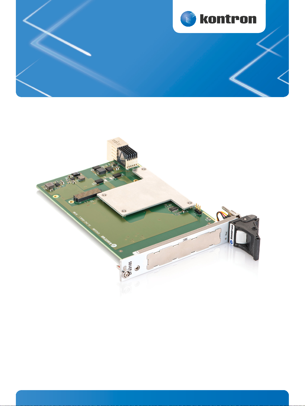
CPS3105
Doc. ID: 1055-0548, Rev. 1.0
Date: July 3, 2013
D R A F T — F O R I N T E R N A L U S E O N L Y
The pulse of innovation
Page 2

User Guide
Revision History
Publication Title: CPS3105 User Guide
Doc. ID: 1055-0548
Rev. Brief Description of Changes Date of Issue
1.0 Initial issue 3-Jul-2013
CPS3105
Imprint
Kontron Europe GmbH may be contacted via the following:
MAILING ADDRESS TELEPHONE AND E-MAIL
Kontron Europe GmbH +49 (0) 800-SALESKONTRON
Sudetenstraße 7 sales@kontron.com
D - 87600 Kaufbeuren Germany
For further information concerning other Kontron products, please visit our Internet website:
www.kontron.com.
Disclaimer
Copyright © 2013 Kontron AG. All rights reserved. All data is for information purposes only and not
guaranteed for legal purposes. Information has been carefully checked and is believed to be accurate;
however, no responsibility is assumed for inaccuracies. Kontron and the Kontron logo and all other
trademarks or registered trademarks are the property of their respective owners and are recognized.
Specifications are subject to change without notice.
www.kontron.com
D R A F T — F O R I N T E R N A L U S E O N L Y
2
Page 3

User Guide
CPS3105
Contents
Revision History ..........................................................................................................2
Imprint .....................................................................................................................2
Disclaimer ..................................................................................................................2
Contents ....................................................................................................................3
Tables .......................................................................................................................4
Warranty ....................................................................................................................5
Proprietary Note ..........................................................................................................5
Trademarks ................................................................................................................5
Environmental Protection Statement ................................................................................5
1 Introduction ....................................................................................... 6
1.1 Board Overview ........................................................................................... 6
1.2 Board Diagrams........................................................................................... 6
1.2.1 Functional Block Diagram .............................................................................. 6
1.2.2 Front Panel ................................................................................................ 7
1.2.3 Board Layout .............................................................................................. 7
1.3 Technical Specification ................................................................................. 8
1.4 Standards .................................................................................................. 8
1.5 Related Publications..................................................................................... 9
2 Functional Description ......................................................................... 10
2.1 Board Interfaces......................................................................................... 10
2.1.1 Front Panel LED .......................................................................................... 10
2.1.2 XMC Interface ............................................................................................ 10
2.1.3 CompactPCI Serial Interface .......................................................................... 10
3 Installation ....................................................................................... 11
3.1 Safety ...................................................................................................... 11
3.2 General Instructions on Usage ....................................................................... 11
3.3 Board Installation ...................................................................................... 12
3.3.1 Hot Swap Insertion ..................................................................................... 12
3.3.2 Hot Swap Removal ...................................................................................... 12
3.3.3 XMC Module Installation ............................................................................... 12
D R A F T — F O R I N T E R N A L U S E O N L Y
www.kontron.com
3
Page 4

User Guide
CPS3105
Tables
1 CPS3105 Main Specifications ..................................................................................8
2 Standards ..........................................................................................................8
3 Additional Standards for Boards Ordered with Ruggedized Service ................................... 9
4 Related Publications .............................................................................................9
5 Power Status LED ............................................................................................... 10
6 Compatibility Identification Block acc. to ANSI/VITA 42.3 ........................................... 10
7 XMC Module Current ............................................................................................ 10
Figures
1 CPS3105 Functional Block Diagram ........................................................................ 7
2 4 HP CPS3105 Front Panel .................................................................................... 8
3 4 HP CPS3105 Board Layout (Top View) ................................................................... 8
www.kontron.com
D R A F T — F O R I N T E R N A L U S E O N L Y
4
Page 5

User Guide
CPS3105
Warranty
This Kontron product is warranted against defects in material and workmanship for the warranty period
from the date of shipment. During the warranty period, Kontron will at its discretion decide to repair
or replace defective products.
Within the warranty period, the repair of products is free of charge as long as warranty conditions are
observed.
The warranty does not apply to defects resulting from improper or inadequate maintenance or handling
by the buyer, unauthorized modification or misuse, operation outside of the product’s environmental
specifications or improper installation or maintenance.
Kontron will not be responsible for any defects or damages to other products not supplied by Kontron
that are caused by a faulty Kontron product.
Proprietary Note
This document contains information proprietary to Kontron. It may not be copied or transmitted by any
means, disclosed to others, or stored in any retrieval system or media without the prior written consent
of Kontron or one of its authorized agents.
The information contained in this document is, to the best of our knowledge, entirely correct. However, Kontron cannot accept liability for any inaccuracies or the consequences thereof, or for any liability
arising from the use or application of any circuit, product, or example shown in this document.
Kontron reserves the right to change, modify, or improve this document or the product described herein, as seen fit by Kontron without further notice.
Trademarks
This document may include names, company logos and trademarks, which are registered trademarks
and, therefore, proprietary to their respective owners.
Environmental Protection Statement
This product has been manufactured to satisfy environmental protection requirements where possible.
Many of the components used (structural parts, printed circuit boards, connectors, etc.) are capable
of being recycled.
Final disposition of this product after its service life must be accomplished in accordance with applicable country, state, or local laws or regulations.
www.kontron.com
D R A F T — F O R I N T E R N A L U S E O N L Y
5
Page 6

User Guide
Onboard Power Supplies
12 V
Power Enable
Pwr LED
Onboard Power Supplies
12 V
PCIe
P1
Hot Swap Handle
Power Enable
Front
CompactPCI
Serial
x4 PCIe 3.0
PEX 8712
PCI Express
Switch
x8 PCIe 2.1
XMC Connector
PCIe x8
CPS3105
1 Introduction
1.1 Board Overview
The CPS3105 is a 3U CompactPCI® Serial carrier board that provides support for one XMC module. The
carrier board is intended to offer system designers a cost-effective solution to expand the systems I/O
capability using a wide range of XMCs available on the market. The CPS3105 is equipped with a dedicated PCI Express switch between the onboard XMC connector and the CPCI-S.0 system connector providing two advantages. First, it decouples and buffers the PCI Express signals and restores signal
integrity. Second, it is able to convert one x4 PCI Express 3.0 data stream from the system side into one
x8 PCI Express 2.1 data stream to the XMC side. Thus, maximum data bandwidth can be provided to commonly available XMC modules based on PCI Express 2.1.
1.2 Board Diagrams
The following diagrams provide additional information concerning board functionality and component
layout.
1.2.1 Functional Block Diagram
Figure 1: CPS3105 Functional Block Diagram
www.kontron.com
D R A F T — F O R I N T E R N A L U S E O N L Y
6
Page 7

1.2.2 Front Panel
CPS3105
Pwr
XMC
Power Status LED
Pwr (green): Power Status of the CPS3105
PEX 8712
PCI Express
Switch
P1
Pwr LED
J2
Heat Sink
Figure 2: 4 HP CPS3105 Front Panel
User Guide
CPS3105
1.2.3 Board Layout
Figure 3: 4 HP CPS3105 Board Layout (Top View)
D R A F T — F O R I N T E R N A L U S E O N L Y
www.kontron.com
7
Page 8

1.3 Technical Specification
Table 1: CPS3105 Main Specifications
FEATURES SPECIFICATIONS
PCI Express Switch ExpressLane™ PEX 8712 PCI Express 3.0 switch from PLX Technology used to provide
maximum performance to an XMC module by spitting down the x4 PCI Express 3.0
Switch
XMC XMC connector, J2 (P15), for connecting an XMC module to the CPS3105
CompactPCI Serial CompactPCI Serial interface on connector P1:
Connectors
Hot Swap Hot swap handle with integrated hot swap switch for shutting down the power sup-
Hot
Swap
Front Panel LED Power Status LED:
LED
Mechanical 3U, 4 HP, CompactPCI Serial-compliant form factor
Power Consumption approx. 4.7 W (without XMC module)
Power Supply +12V DC in accordance with the CompactPCI® Serial Specification
Temperature Range Operational: 0°C to +60°C Standard
Recommended Airflow Volumetric Flow Rate: > 10 cfm
General
Climatic Humidity 93% RH at 40 °C, non-condensing (acc. to IEC 60068-2-78)
Dimensions 100 mm x 160 mm
Board Weight 140 grams
interface to a x8 PCI Express 2.1/1.0 interface
» Compliant with PICMG® CPCI-S.0 R 1.0 CompactPCI® Serial Specification
» Support for one x4 PCI Express 3.0 interface
plies in order to safely remove the CPS3105 from the system
» Pwr (green): Power Status of the CPS3105
Storage: -40°C to +85°C Without XMC module
Sufficient airflow must be provided to ensure optimal operation and long-term
reliability of the CPS3105.
User Guide
CPS3105
-40°C to +85°C Extended
1.4 Standards
This product complies with the requirements of the following standards.
Table 2: Standards
TYPE ASPECT STANDARD
CE Emission EN55022, EN50121-3-2, EN61000-6-3
Immission EN55024, EN50121-3-2, EN61000-6-2
Electrical Safety EN60950-1
Mechanical Mechanical Dimensions IEEE 1101.10
Environmental Climatic Humidity IEC60068-2-78
WEEE Directive 2002/96/EC
Waste electrical and electronic equipment
RoHS 2 Directive 2011/65/EU
Restriction of the use of certain hazardous sub-
stances in electrical and electronic equipment
D R A F T — F O R I N T E R N A L U S E O N L Y
www.kontron.com
8
Page 9

User Guide
CPS3105
In addition, boards ordered with the ruggedized service comply with the following standards as well.
Table 3: Additional Standards for Boards Ordered with Ruggedized Service
TYPE ASPECT STANDARD REMARKS
Environmental Vibration
(Sinusoidal)
Single Shock IEC60068-2-27
IEC60068-2-6
IEC61131-2
IEC61131-2
Ruggedized version test parameters:
9-150 (Hz) frequency range
1 (g) acceleration
1 (oct/min) sweep rate
10 cycles/axis
3 axis
Ruggedized version test parameters:
15 (g) acceleration
11 (ms) shock duration half sine
3 number of shocks per direction (total: 18)
6 directions
5 (s) recovery time
Note: Customers desiring to perform further environmental testing of the CPS3105 must contact
Kontron for assistance prior to performing any such testing.
Boards without conformal coating must not be exposed to a change of temperature which
can lead to condensation, as it may cause irreversible damage especially when the board
is powered up again.
Kontron does not accept any responsibility for damage to products resulting from destructive environmental testing.
1.5 Related Publications
The following publications contain information relating to this product.
Table 4: Related Publications
PRODUCT PUBLICATION
CompactPCI Serial Systems PICMG® CPCI-S.0 R 1.0 CompactPCI® Serial Specification
All Kontron products Product Safety and Implementation Guide, ID 1021-9142
XMC ANSI/VITA 42.0-200x XMC Switched Mezzanine Card Auxiliary Standard
ANSI/VITA 42.3-2006 XMC PCI Express Protocol Layer Standard
www.kontron.com
D R A F T — F O R I N T E R N A L U S E O N L Y
9
 Loading...