

Page 1
If it's embedded, it's Kontron.
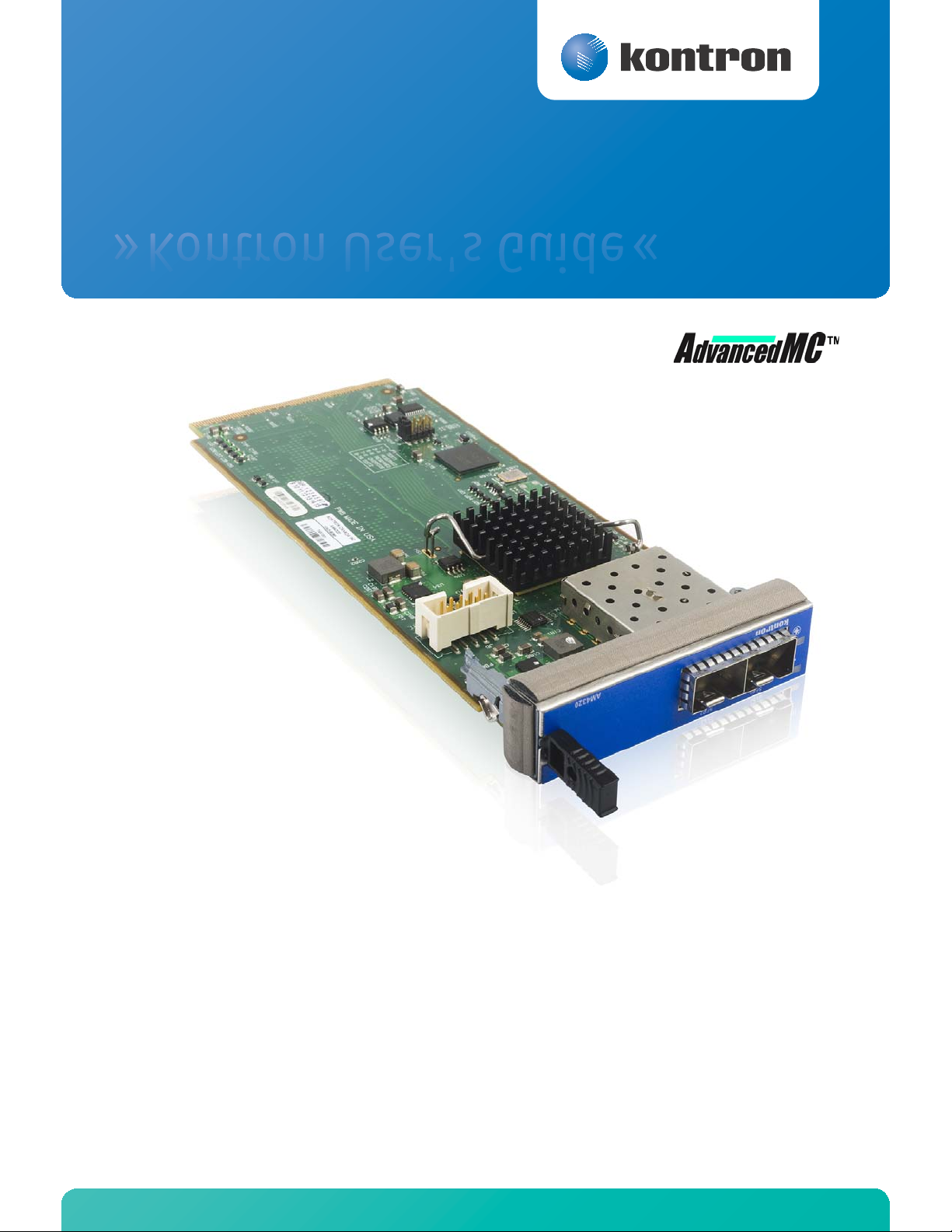
» Kontron User's Guide «
AM4320
Document Revision 1.0
April 2012
Page 2

www.kontron.com
Revision History
Rev. Index Brief Description of Changes Date of Issue
1.0 First Release April 2012
Customer Service
Contact Information: Kontron Canada, Inc.
4555 Ambroise-Lafortune
Boisbriand, Québec, Canada
J7H 0A4
Tel: (450) 437-5682
(800) 354-4223
Fax: (450) 437-8053
E-mail: support@ca.kontron.com
Visit our site at: www.kontron.com
© 2011 Kontron, an International Corporation. All rights reserved.
The information in this user's guide is provided for reference only. Kontron does not assume any liability
arising out of the application or use of the information or products described herein. This user's guide may
contain or reference information and products protected by copyrights or patents and does not convey any
license under the patent rights of Kontron, nor the rights of others.
Kontron is a registered trademark of Kontron. All trademarks, registered trademarks, and trade names used
in this user's guide are the property of their respective owners. All rights reserved. Printed in Canada. This
user's guide contains information proprietary to Kontron. Customers may reprint and use this user's guide in
other publications. Customers may alter this user's guide and publish it only after they remove the Kontron
name, cover, and logo.
Kontron Modular Computer GMBH
Sudetenstrasse 7
87600 Kaufbeuren
Germany
+49 (0) 8341 803 333
+49 (0) 8341 803 339
support-kom@kontron.com
Kontron reserves the right to make changes without notice in product or component design as warranted by
evolution in user needs or progress in engineering or manufacturing technology. Changes that affect the
operation of the unit will be documented in the next revision of this user's guide.
i AM4320
Page 3

www.kontron.com
Table of Contents
Safety Instructions . . . . . . . . . . . . . . . . . . . . . . . . . . . . . . . . . . . . . . . . . . . . . . . . . . . . . . . vi
Before You Begin . . . . . . . . . . . . . . . . . . . . . . . . . . . . . . . . . . . . . . . . . . . . . . . . . . . . . . . . . . . . . . . vi
Preventing Electrostatic Discharge . . . . . . . . . . . . . . . . . . . . . . . . . . . . . . . . . . . . . . . . . . . . . . . . .vii
Preface . . . . . . . . . . . . . . . . . . . . . . . . . . . . . . . . . . . . . . . . . . . . . . . . . . . . . . . . . . . . . . . . viii
How to Use This Guide . . . . . . . . . . . . . . . . . . . . . . . . . . . . . . . . . . . . . . . . . . . . . . . . . . . . . . . . . . viii
Customer Comments. . . . . . . . . . . . . . . . . . . . . . . . . . . . . . . . . . . . . . . . . . . . . . . . . . . . . . . . . . . . viii
Storing Boards . . . . . . . . . . . . . . . . . . . . . . . . . . . . . . . . . . . . . . . . . . . . . . . . . . . . . . . . . . . . . . . . viii
Advisory Conventions . . . . . . . . . . . . . . . . . . . . . . . . . . . . . . . . . . . . . . . . . . . . . . . . . . . . . . . . . . . . ix
Unpacking . . . . . . . . . . . . . . . . . . . . . . . . . . . . . . . . . . . . . . . . . . . . . . . . . . . . . . . . . . . . . . . . . . . . . ix
Regulatory & Compliance Statements . . . . . . . . . . . . . . . . . . . . . . . . . . . . . . . . . . . . . . . . . . . . . . . .x
Limited Warranty . . . . . . . . . . . . . . . . . . . . . . . . . . . . . . . . . . . . . . . . . . . . . . . . . . . . . . . . . . . . . . . xi
Table of Contents
1. Product Description . . . . . . . . . . . . . . . . . . . . . . . . . . . . . . . . . . . . . . . . . . . . . . . . . . . . . . . 2
1.1 Product Overview. . . . . . . . . . . . . . . . . . . . . . . . . . . . . . . . . . . . . . . . . . . . . . . . . . . . . . . . . . . . . 2
1.2 What’s Included. . . . . . . . . . . . . . . . . . . . . . . . . . . . . . . . . . . . . . . . . . . . . . . . . . . . . . . . . . . . . . 2
1.3 Board Specifications . . . . . . . . . . . . . . . . . . . . . . . . . . . . . . . . . . . . . . . . . . . . . . . . . . . . . . . . . . 3
1.4 Compliance . . . . . . . . . . . . . . . . . . . . . . . . . . . . . . . . . . . . . . . . . . . . . . . . . . . . . . . . . . . . . . . . . 4
1.5 Hot-Swap Capability . . . . . . . . . . . . . . . . . . . . . . . . . . . . . . . . . . . . . . . . . . . . . . . . . . . . . . . . . . 4
2. Board Features. . . . . . . . . . . . . . . . . . . . . . . . . . . . . . . . . . . . . . . . . . . . . . . . . . . . . . . . . . . 6
2.1 Block Diagram . . . . . . . . . . . . . . . . . . . . . . . . . . . . . . . . . . . . . . . . . . . . . . . . . . . . . . . . . . . . . . . 6
2.2 Ethernet Interfaces . . . . . . . . . . . . . . . . . . . . . . . . . . . . . . . . . . . . . . . . . . . . . . . . . . . . . . . . . . . 6
2.2.1 Intel 82599ES Ethernet Controller . . . . . . . . . . . . . . . . . . . . . . . . . . . . . . . . . . . . . . . . . . . .6
2.3 MMC Boot Block . . . . . . . . . . . . . . . . . . . . . . . . . . . . . . . . . . . . . . . . . . . . . . . . . . . . . . . . . . . . . . 6
2.4 Hardware Management Overview . . . . . . . . . . . . . . . . . . . . . . . . . . . . . . . . . . . . . . . . . . . . . . . . 7
2.4.1 Sensor Data Record (SDR). . . . . . . . . . . . . . . . . . . . . . . . . . . . . . . . . . . . . . . . . . . . . . . . . . .7
2.4.2 Hardware Sensors . . . . . . . . . . . . . . . . . . . . . . . . . . . . . . . . . . . . . . . . . . . . . . . . . . . . . . . . .8
2.4.3 Field Replaceable Unit (FRU) Information . . . . . . . . . . . . . . . . . . . . . . . . . . . . . . . . . . . . . .9
2.4.4 E-Keying . . . . . . . . . . . . . . . . . . . . . . . . . . . . . . . . . . . . . . . . . . . . . . . . . . . . . . . . . . . . . . . .9
2.4.5 MMC Firmware Code . . . . . . . . . . . . . . . . . . . . . . . . . . . . . . . . . . . . . . . . . . . . . . . . . . . . . . .9
2.4.6 Firmware Upgrade Procedure . . . . . . . . . . . . . . . . . . . . . . . . . . . . . . . . . . . . . . . . . . . . . . . .9
2.4.7 Hot-Swap Process . . . . . . . . . . . . . . . . . . . . . . . . . . . . . . . . . . . . . . . . . . . . . . . . . . . . . . . .10
ii AM4320
Page 4

Table of Contents
www.kontron.com
2.5 LEDs Signification . . . . . . . . . . . . . . . . . . . . . . . . . . . . . . . . . . . . . . . . . . . . . . . . . . . . . . . . . . . 10
2.5.1 Hot Swap (Blue) . . . . . . . . . . . . . . . . . . . . . . . . . . . . . . . . . . . . . . . . . . . . . . . . . . . . . . . . .10
2.5.2 Out of service (Red/Amber)[default : red] . . . . . . . . . . . . . . . . . . . . . . . . . . . . . . . . . . . . .10
2.5.3 Health Led(Amber/Green)[default : green] . . . . . . . . . . . . . . . . . . . . . . . . . . . . . . . . . . . .10
2.5.4 SFP+ Led [Green] . . . . . . . . . . . . . . . . . . . . . . . . . . . . . . . . . . . . . . . . . . . . . . . . . . . . . . . .11
3. Installing the Board. . . . . . . . . . . . . . . . . . . . . . . . . . . . . . . . . . . . . . . . . . . . . . . . . . . . . . 13
3.1 Board Hot Swap and Installation . . . . . . . . . . . . . . . . . . . . . . . . . . . . . . . . . . . . . . . . . . . . . . . 13
3.1.1 Installing an AMC . . . . . . . . . . . . . . . . . . . . . . . . . . . . . . . . . . . . . . . . . . . . . . . . . . . . . . . .13
3.1.2 Removing an AMC . . . . . . . . . . . . . . . . . . . . . . . . . . . . . . . . . . . . . . . . . . . . . . . . . . . . . . . .13
A. Connector Pinouts . . . . . . . . . . . . . . . . . . . . . . . . . . . . . . . . . . . . . . . . . . . . . . . . . . . . . . .A-1
A.1 AMC (J1) . . . . . . . . . . . . . . . . . . . . . . . . . . . . . . . . . . . . . . . . . . . . . . . . . . . . . . . . . . . . . . . . . .A-1
A.2 SFP+ Connectors . . . . . . . . . . . . . . . . . . . . . . . . . . . . . . . . . . . . . . . . . . . . . . . . . . . . . . . . . . . .A-2
B. Getting Help. . . . . . . . . . . . . . . . . . . . . . . . . . . . . . . . . . . . . . . . . . . . . . . . . . . . . . . . . . . .B-1
B.1 Returning Defective Merchandise. . . . . . . . . . . . . . . . . . . . . . . . . . . . . . . . . . . . . . . . . . . . . . . . 2
B.2 When Returning a Unit . . . . . . . . . . . . . . . . . . . . . . . . . . . . . . . . . . . . . . . . . . . . . . . . . . . . . . .B-3
iii AM4320
Page 5

List of Figures
www.kontron.com
List of Figures
Figure 2-1: AM4320 Block Diagram . . . . . . . . . . . . . . . . . . . . . . . . . . . . . . . . . . . . . . . . . . . . . . . . . . . . . . .6
iv AM4320
Page 6

List of Tables
www.kontron.com
List of Tables
Table 1-1 Board Specifications. . . . . . . . . . . . . . . . . . . . . . . . . . . . . . . . . . . . . . . . . . . . . . . . . . . . . . . . . . 3
Table 2-1 Hardware Sensors . . . . . . . . . . . . . . . . . . . . . . . . . . . . . . . . . . . . . . . . . . . . . . . . . . . . . . . . . . . 8
v AM4320
Page 7
www.kontron.com
Safety Instructions
Before You Begin
Before handling the board, read the instructions and safety guidelines on the following pages to prevent
damage to the product and to ensure your own personal safety. Refer to the "Advisories" section in the
Preface for advisory conventions used in this user's guide, including the distinction between Warnings,
Cautions, Important Notes, and Notes.
• Always use caution when handling/operating the computer. Only qualified, experienced,
authorized electronics service personnel should access the interior of the computer. The power
supplies produce high voltages and energy hazards, which can cause bodily harm.
• Use extreme caution when installing or removing components. Refer to the installation
instructions in this user's guide for precautions and procedures. If you have any questions, please
contact Kontron Technical Support
WARNING
High voltages are present inside the chassis when the unit's power cord is plugged
into an electrical outlet. Turn off system power, turn off the power supply, and then
disconnect the power cord from its source before removing the chassis cover. Turning
off the system power switch does not remove power to components.
vi AM4320
Page 8

www.kontron.com
Preventing Electrostatic Discharge
Static electricity can harm system boards. Perform service at an ESD workstation and follow proper ESD
procedure to reduce the risk of damage to components. Kontron strongly encourages you to follow proper
ESD procedure, which can include wrist straps and smocks, when servicing equipment.
Take the following steps to prevent damage from electrostatic discharge (ESD):
• When unpacking a static-sensitive component from its shipping carton, do not remove the
component's antistatic packing material until you are ready to install the component in a
computer. Just before unwrapping the antistatic packaging, be sure you are at an ESD workstation
or properly grounded. This will discharge any static electricity that may have built up in your body.
• When transporting a sensitive component, first place it in an antistatic container or packaging.
• Handle all sensitive components at an ESD workstation. If possible, use antistatic floor pads and
workbench pads.
• Handle components and boards with care. Don't touch the components or contacts on a board.
Hold a board by its edges or by its metal mounting bracket.
• Do not handle or store system boards near strong electrostatic, electromagnetic, magnetic, or
radioactive fields.
vii AM4320
Page 9

www.kontron.com
Preface
How to Use This Guide
This user's guide is designed to be used as step-by-step instructions for installation, and as a reference for
operation, troubleshooting, and upgrades.
You can find the latest release of this User's Guide at:
http://www.kontron.com
For the circuits, descriptions and tables indicated, Kontron assumes no responsibility as far as patents or
other rights of third parties are concerned.
The following is a summary of chapter contents:
• Chapter 1, Product Description
• Chapter 2, Board Features
• Chapter 3, Installing the Board
• Appendix A, Connector Pinout
• Appendix B, Getting Help
or at:ftp://ftp.kontron.ca/support/Products/Product_List.html
Customer Comments
If you have any difficulties using this user's guide, discover an error, or just want to provide some feedback,
please send a message to: Tech.Writer@ca.kontron.com
or problems as soon as possible and post the revised user's guide on our Web site.
. Detail any errors you find. We will correct the errors
Storing Boards
Electronic boards are sensitive devices. Do not handle or store device near strong electrostatic,
electromagnetic, magnetic or radioactive fields.
viii AM4320
Page 10

www.kontron.com
Advisory Conventions
Seven types of advisories are used throughout the user guides to provide helpful information or to alert you
to the potential for hardware damage or personal injury. They are Note, Signal Paths, Related Jumpers, BIOS
Settings, Software Usage, Cautions, and Warnings.Use caution when servicing electrical components. Use
caution when servicing electrical components.The following is an example of each type of advisory.
Disclaimer: We have tried to identify all situations that may pose a warning or a caution condition in this
user's guide. However, Kontron does not claim to have covered all situations that might require the use of a
Caution or a Warning.
Note:
Indicate information that is important for you to know.
Signal Path:
Indicate the places where you can fin the signal on the board.
Jumper Settings:
Indicate the jumpers that are related to this sections.
BIOS Settings:
Indicate where you can set this option in the BIOS.
Software Usage:
Indicates how you can access this feature through software.
CAUTION
Indicate potential damage to hardware and tells you how to avoid the problem.
WARNING
Indicates potential for bodily harm and tells you how to avoid the problem.
Unpacking
Follow these recommendations while unpacking:
• Remove all items from the box. If any items listed on the purchase order are missing, notify
Kontron customer service immediately.
• Inspect the product for damage. If there is damage, notify Kontron customer service immediately.
• Save the box and packing material for possible future shipment.
ix AM4320
Page 11

www.kontron.com
Regulatory & Compliance Statements
FCC Compliance Statement for Class B Devices
This equipment has been tested and found to comply with the limits for a Class B digital device,
pursuant to Part 15 of the FCC Rules. These limits are designed to provide reasonable protection
against harmful interference in a residential installation. This equipment generated, uses and can
radiate radio frequency energy and, if not installed and used in accordance with the instructions
may cause harmful interference to radio communications. However, there is no guarantee that
interference will not occur in a particular installation. If this equipment does cause harmful
interference to radio or television reception, which can be determined by turning the equipment
off and on, the user is encouraged to try to correct the interference by one or more of the following
measures:
•Reorient or relocate the receiving antenna.
•Increase the separation between the equipment and receiver.
•Connect the equipment into an outlet on a circuit different from that to which the receiver is
connected.
•Consult the dealer or an experience radio/TV technician for help.
WARNING
This is a Class B product. If not installed in a properly shielded enclosure and used in
accordance with this User's Guide, this product may cause radio interference in
which case users may need to take additional measures at their own expense.
UL Certification
This product bears the combined UL Recognized Component Mark for Canada and U.S. It indicates
investigations to the UL Standard for Safety of Information Technology Equipment, Including
Electrical Business Equipment. It is destinated to be used in end-product equipment where the
acceptability of the combination is determined by Underwriters Laboratories Inc.
CE Certification
The product described in this user's guide was tested in a representative system and is found to be
compliant with the CE marking requirements. For computer systems to remain CE compliant, only
CE-compliant parts may be used. Maintaining CE compliance also requires proper cable and cabling
techniques. Although Kontron offers accessories, the customer must ensure that these products
are installed with proper shielding to maintain CE compliance. Kontron does not offer engineering
services for designing cabling systems. In addition, Kontron will not retest or recertify systems or
components that have been reconfigured by customers.
x AM4320
Page 12

www.kontron.com
Limited Warranty
Kontron grants the original purchaser of Kontron's products a TWO YEAR LIMITED HARDWARE WARRANTY as
described in the following. However, no other warranties that may be granted or implied by anyone on behalf
of Kontron are valid unless the consumer has the express written consent of Kontron.
Kontron warrants their own products, excluding software, to be free from manufacturing and material
defects for a period of 24 consecutive months from the date of purchase. This warranty is not transferable nor
extendible to cover any other users or long- term storage of the product. It does not cover products which
have been modified, altered or repaired by any other party than Kontron or their authorized agents.
Furthermore, any product which has been, or is suspected of being damaged as a result of negligence,
improper use, incorrect handling, servicing or maintenance, or which has been damaged as a result of
excessive current/voltage or temperature, or which has had its serial number(s), any other markings or parts
thereof altered, defaced or removed will also be excluded from this warranty.
If the customer's eligibility for warranty has not been voided, in the event of any claim, he may return the
product at the earliest possible convenience to the original place of purchase, together with a copy of the
original document of purchase, a full description of the application the product is used on and a description
of the defect. Pack the product in such a way as to ensure safe transportation (see our safety instructions).
Kontron provides for repair or replacement of any part, assembly or sub-assembly at their own discretion, or
to refund the original cost of purchase, if appropriate. In the event of repair, refunding or replacement of
any part, the ownership of the removed or replaced parts reverts to Kontron, and the remaining part of the
original guarantee, or any new guarantee to cover the repaired or replaced items, will be transferred to cover
the new or repaired items. Any extensions to the original guarantee are considered gestures of goodwill, and
will be defined in the "Repair Report" issued by Kontron with the repaired or replaced item.
Kontron will not accept liability for any further claims resulting directly or indirectly from any warranty claim,
other than the above specified repair, replacement or refunding. In particular, all claims for damage to any
system or process in which the product was employed, or any loss incurred as a result of the product not
functioning at any given time, are excluded. The extent of Kontron liability to the customer shall not exceed
the original purchase price of the item for which the claim exists.
Kontron issues no warranty or representation, either explicit or implicit, with respect to its products'
reliability, fitness, quality, marketability or ability to fulfill any particular application or purpose. As a result,
the products are sold "as is," and the responsibility to ensure their suitability for any given task remains that
of the purchaser. In no event will Kontron be liable for direct, indirect or consequential damages resulting
from the use of our hardware or software products, or documentation, even if Kontron were advised of the
possibility of such claims prior to the purchase of the product or during any period since the date of its
purchase.
Please remember that no Kontron employee, dealer or agent is authorized to make any modification or
addition to the above specified terms, either verbally or in any other form, written or electronically
transmitted, without the company's consent.
xi AM4320
Page 13

Chapter 1
Product Description
www.kontron.com
1.1 Product Overview....................................................2
1.2 What’s Included .....................................................2
1.3 Board Specifications ...............................................3
1.4 Compliance ...........................................................4
1.5 Hot-Swap Capability................................................4
Page 14

www.kontron.com
1. Product Description
1.1 Product Overview
The Kontron AM4320 Dual 10GbE module is the ideal AdvancedMC unit for network applications that require
multiple ports directly from an AdvancedTCA processor blade, such as the AT8060 Dual 8-Core Xeon ATCA
Processor blade.
• Provides expanded bandwidth for ATCA node blades (AT8060) and MicroTCA platforms
• Two 10Gigabit Ethernet on SFP+ ports supported by Intel 82599ES Ethernet controller implementation
• PCI Express GEN 2 x8 interface between AMC edge connector and controller
• Supports remote management via IPMI v2.0 and features a Management Controller that is run-time field
reprogrammable without any payload impact.
• Designed to meet NEBS compliance - Reliability, Availability, Serviceability, Maintainability
1.2 What’s Included
The shipping box contains the following items
• One Quick Reference Sheet.
• One Documentation & Drivers disk
• One AM4320 board
If any item is missing or damaged, contact the supplier.
2 AM4320
Page 15

www.kontron.com
1.3 Board Specifications
Table 1-1: Board Specifications
Features Description
• AMC.0 R2.0
Compliancy
OS Compatibility
IPMI Features
Supervisory
Mechanical • 181.5 x 75 x 18.96 mm, Single-width mid-size
Power Requirements
Environmental
Temperature*
Environmental
Humidity*
Environmental Altitude*
Environmental Shock*
Environmental
Vibration*
Safety / EMC
Warranty • Two years limited warranty
• AMC.1 R2.0
• PICMG HPM.1 R1.0
• Red Hat Enterprise Linux Server 5.5 64-bit
• Red Hat Enterprise Linux Server 6.0 64-bit
• Windriver PNE 4.0
• Management Controller compliant to PICMG 3.0, AMC.0 R2.0 and IPMI v2.0.
• Management Controller is run-time field-reprogrammable without payload impact.
• Robust fail-safe reprogramming implementation (which includes two firmware images) that
can perform an automatic or manual rollback if a problem occurs during critical reprogramming
phases.
• Remote upgrade capability from any IPMI interface (via IPMB-L).
• Management Controller self test which can detect failure in its code integrity and trigger an
automatic rollback.
• Hardware system monitor through IPMI (voltages, currents, temperature), temperature
monitor / alarm; board temperature sensor, power failure.
• Management power is less than 150mA peak at 3.3V
• Payload power is 12W
• Operating: 0-55°C/32-131°F
• Storage and Transit: -40 to +70°C/-40 to 158°F
• Operating: 15% to 90% @55°C/131°F non-condensing
• Storage and Transit: 5% to 95% @ 40°C/104°F non-condensing
• Operating: 4,000 m / 13,123 ft
• Storage and Transit: 15,000 m / 49,212 ft
• Operating: 30G, half-sine 11ms, each axis
• Storage and Transit: Bellcore GR-63-CORE Section 4.3
• Operating: 1.0G, 5-500Hz each axis
• Storage and Transit: 2.0G, 5-50Hz; 3.0G, 50-500Hz each axis
• Meet or exceed:
• Safety: UL 60950-1 1st Ed.; CSA C22.2 No 60950-1-03; EN 60950-1:2001; IEC60950-1
• EMI/EMC: FCC 47 CFR Part 15, Class B; CE Mark to EN55022/EN55024
* Designed to meet or exceed
3 AM4320
Page 16

www.kontron.com
1.4 Compliance
This product conforms to the following specifications:
• PICMG3.0R1.0 (Advanced TCA core specification)
• AMC.0 R2.0
• AMC.1 R2.0
1.5 Hot-Swap Capability
The AM4320 supports Full Hot Swap capability as per PICMG3.0R1.0. It can be removed from or installed in
the system while it is on (without powering-down the system). Please refer to the PICMG3.0R1.0
specification for additional details. (OS must support PCIe Hot Plug)
4 AM4320
Page 17

Chapter 2
Board Features
www.kontron.com
2.1 Block Diagram ........................................................ 6
2.2 Ethernet Interfaces.................................................. 6
2.3 MMC Boot Block ...................................................... 6
2.4 Hardware Management Overview ................................ 7
2.5 LEDs Signification ................................................... 10
Page 18

www.kontron.com
2. Board Features
!"
#!$%
!&!&$
'()
)*+,,-
.
.
.
/
0
120
0, 3
%!
.
4#451 #
4#451 #
6
6+
!!
.7
.
.
7
8
.: .:
21
;& 6%
#54#4
#5#
3&!2!,
,!<
2.1 Block Diagram
Figure 2-1: AM4320 Block Diagram
2.2 Ethernet Interfaces
2.2.1 Intel 82599ES Ethernet Controller
The AMC interface is implemented with one Intel dual-port 10 Gigabit Ethernet controller. The controller
supporting two 10GbE SFP+ modules. See www.intel.com
Signal Path:
The two SFP+ connectors are on the faceplate.
for additional details on this controller.
2.3 MMC Boot Block
The MMC runs a firmware from its internal 256KB flash. It is programmed by an additional 8K boot block.I
stores the active and previous MMC firmware in a dedicated flash memory. The boot block activates the MMC
image and can fall back to the secondary image in case of problems.
6 AM4320
Page 19

www.kontron.com
2.4 Hardware Management Overview
The AMC Carrier communicates with the Module Management Controller (MMC) using the IPMB_L channel.
The memory subsystem of the MMC consists of an integrated flash memory to hold the MMC operation code
and integrated RAM for data. The field replacement unit (FRU) inventory information is stored in the
nonvolatile memory on an EEPROM and connected via a local I2C interface to the MMC microcontroller. It is
possible to store up to 4 KBytes within the FRU inventory information. Event generation over IPMB-L bus to
reach the AMC Carrier that forward it to the ShMc ensure that 'post-mortem' logging information is available
even if the power of the AMC is disabled.
The onboard DC voltages and temperature are monitored by the MMC microcontroller device. The MMC will
send an event to the Carrier if any of the thresholds are exceeded.
To increase the reliability of the AM4320 management subsystem, an external watchdog supervisor for the
MMC is implemented. The MMC must strobe the external watchdog at two-second intervals to indicate
continuity of operation of the board's management subsystem. If the MMC ceases to strobe the watchdog
supervisor, the watchdog isolates the MMC from the IPMBs and resets the MMC. The watchdog supervisor
does not reset the payload power the restart of the MMC will not affect the payload and will restore the
previous Module Hot Swap state. The watchdog timeout expires after six seconds if strobes are not received.
The external watchdog supervisor is not configurable and must not be confused with the IPMI v1.5 watchdog
timer commands.
A boot block located on the microcontroller is responsible for managinge the MMC's fail safe firmware
upgrade process. It can sotre two Firmware copies located on an external flash memory. If a failure occurs
during firmware upgrade, the Boot Block will automatically rollback to the redundant MMC firmware image.
2.4.1 Sensor Data Record (SDR)
Every sensor on the baseboard is associated with a Sensor Data Record (SDR). Sensor Data Records contain
information about the sensors identification such as sensor type, sensor name, sensor unit. SDR also contain
the configuration of a specific sensor such as threshold/hysteresis and event generation capabilities that
specify sensor behavior. Some fields of the sensor SDR are configurable through IPMI v1.5 commands and
are set to built-in initial values. Finally one field which is the sensor owner must reflect the module addresses
that allow the AMC Carrier to identify the owner of the SDR when it is scanned by the module management
controller and merged within the AMC Carrier Device SDR repository.
From an IPMI perspective, the AM4320 management controller is set up as a satellite management controller
(SMC). It supports sensor devices, and uses the IPMI static sensor population feature of IPMI v1.5 to merge
the hot swapped AMC sensor with the carrier board sensors population. The AMC Carrier is informed of AMC
insertion events through the AMC Module Hot Swap sensor and a radial presence line on the AMC connector.
All SDRs can be queried using Device SDR commands to the firmware. Module sensors that have been
implemented are listed the next section.
7 AM4320
Page 20

www.kontron.com
2.4.2 Hardware Sensors
Table 2-1: Hardware Sensors
Sensor Name Voltage/Signals Monitored Scanning Enabled
under Power
State
IPMI Info-1 Internal IPMC firmware diagnostic * N
IPMI Info-2 Internal IPMC firmware diagnostic * N
FRU Agent Board FRU Data agent that verify FRU Data validity * N
ModuleHotSwap AMC HS State * N
IPMBL State Operational state of IPMB-L * N
MMC Storage Err
MMC Reboot IPMC reboot detection * N
Ver Change IPMC firmware upgrade detection * N
Temp Board Board air outlet temperature * X
Temp LAN LAN Temperature * X
Temp MMC MMC Temperature * X
Vcc +3.3V SUS 3.3 V management * X
Vcc +12V 12 V payload - X
Vcc +3.3V 3.3 V - X
Vcc +1.2V 1.2V - X
V_PUMP Voltage on board blue LED VPUMP suspend power supply * X
Power State Board State * X
Health Error Board health sensors (aggregation of other sensors) *
Pres SFP1 SFP1 Presence -
Pres SFP2 SFP2 Presence
Management sub-system health: non volatile memory
error.
* N
Health LED
(Green to Amber)
Asserted / Deasserted
X Exceed critical threshold
*Power On/Off
-Power On
N No change
2.4.2.1 IPMB-L Link Sensor
The AM4320 has an IPMB-L links to communicate with the AMC Carrier and other devices on the IPMB-0 bus.
The MMC monitors the bus for any link failure and sends a bus failure event to the AMC Carrier when the
recovery occurs.
8 AM4320
Page 21

www.kontron.com
2.4.2.2 Module Hot Swap
The hot-swap event message conveys the current state of the module, the previous state, and a cause of the
state change as determined by the MMC. Refer to AMC.0 R2.0 Specifications for further details on module
hot-swap states.
2.4.3 Field Replaceable Unit (FRU) Information
The FRU Information provides inventory data about the boards where the FRU Information Device is located.
The part number or version number can be read through software.
FRU information in the AM4320 includes data describing the AM4320 board as per the AMC.0 R2.0
specification. This information is retrieved by the Carrier, enabling reporting of board-specific information
through a standardized mechanism.
Following are the definitions for the multirecord implemented by the firmware as part of Module data.
2.4.4 E-Keying
E-Keying has been defined in the AMC.0 R2.0 Specification to prevent module damage, prevent
misoperation, and verify bay connection compatibility. The FRU data contains the AMC point-to-point
connectivity record as described in Section 3.9.2 of the AMC.0 R2.0 specification.
The Set/Get AMC Port State IPMI commands defined by the AMC.0 specification are used for either granting
or rejecting the E-keys.
2.4.5 MMC Firmware Code
MMC firmware code is organized into boot code and operational code, both of which are stored in a flash
module. Upon an MMC reset, the MMC executes the boot code and performs the following:
1 Self-test to verify the status of its hardware and memory.
2 Performs a checksum of the operational code.
3 Communicates with the Boot Block in order to inform the MMC watchdog that the actual MMC firmware is
suitable for execution.
Upon successful verification of the operational code checksum, the firmware will jump to the operational
code.
2.4.6 Firmware Upgrade Procedure
The board’s designed to support upgrade via HPM commands. Always follow Kontron documentation for all
your upgrade. The instructions are provided with any new software upgrade package.
Upgrades have been designed to be performed without payload impact.
9 AM4320
Page 22

www.kontron.com
2.4.7 Hot-Swap Process
The AM4320 AMC has the ability to be hot-swapped in and out of an AMC Carrier/Chassis. The onboard MMC
manages the AMC's power-up and power-down transitions. The list below illustrates this process for a powerdown request.
1 Ejector latch is opened. HOT_SWAP_PB# assertion. MMC firmware detects the assertion of this signal.
2 MMC sends "Module Handle Open" event message to AMC Carrier. The corresponding M state of AMC
moves from M4-> M5.
3 AMC moves from M5 -> M6 if the ShMC grants the request and then sends the FRU Control requesting
quiesced state to the AMC.
4 The firmware deasserts payload power and sends "Module Quiesced" event message to the AMC where it
transitions from M6 to M1 state.
2.5 LEDs Signification
2.5.1 Hot Swap (Blue)
Solid On (100 % on): FRU Inactive
Long Blink ( 90 % on): FRU Activation Request / FRU Activation In Progress
Solid Off ( 0 % on): FRU Active
Short Blink ( 10 % on): FRU Deactivation Request / FRU Deactivation In Progress
2.5.2 Out of service (Red/Amber)[default : red]
Solid On: IPMC in reset
Fast Blink (~50 % on): IPMC upgrade/rollback in progress
Short Blink (10 % on): FRU Power Denied
Application Defined: May be controlled by application using PICMG API
2.5.3 Health Led(Amber/Green)[default : green]
Green: Health Ok
Amber: Health Error (Critical)
Application Defined: May be controlled by application using PICMG API
10 AM4320
Page 23

www.kontron.com
2.5.4 SFP+ Led [Green]
Green On: Link 10Gbit
Green Blink: Activity 10Gbit
11 AM4320
Page 24

Chapter 3
Chapter 3
Installing the Board
www.kontron.com
3.1 Board Hot Swap and Installation ................................ 13
Page 25

www.kontron.com
3. Installing the Board
3.1 Board Hot Swap and Installation
Some precautions must be taken when connecting or disconnecting a board to:
1 Rail guides must be installed on the enclosure to slide the board to the backplane.
2 Do not force the board if there is mechanical resistance while inserting the board.
3 Use AMC handle to deactivate and extract the board from its enclosure.
WARNING
Always use a grounding wrist wrap before installing or removing the board from a
carrier/ chassis.
3.1.1 Installing an AMC
To install an AMC:
1 Remove the AMC filler panel.
2 Carefully engage the AMC into the card guide. Push the AMC until it fully mates with its connector. Secure
the AMC handle in the locking position.
3 In normal condition, the blue LED shall turn ON as soon as the AMC is fully inserted. When the handle is
closedit will blink and finally turn OFF at the end of the hot swap sequence.
3.1.2 Removing an AMC
To remove an AMC:
1 Open the AMC handle.
2 The blue LED will start blinking; wait until it is solid blue.
3 Extract the AMC by pulling it out with the handle.
Note:
Ensure that your OS is Hot Plug compliant before removing your AMC.
13 AM4320
Page 26

www.kontron.com
A. Connector Pinouts
A.1 AMC (J1)
Pin Signal Pin Signal Pin Signal Pin Signal
B1 GND B43 GND B86 GND B129 RxD15- (N.C.)
B2 12V B44 TxD4+ B87 RxD8- B130 RxD15+ (N.C.)
B3 PS1# B45 TxD4- B88 RxD8+ B131 GND
B4 MP_3V3 B46 GND B89 GND B132 TxD15- (N.C.)
B5 GA0 B47 RxD4+ B90 TxD8- B133 TxD15+ (N.C.)
B6 RSV B48 RxD4- B91 TxD8+ B134 GND
B7 GND B49 GND B92 GND B135 RxD16-(N.C.)
B8 RSV B50 TxD5+ B93 RxD9- B136 RxD16+(N.C.)
B9 12V B51 TxD5- B94 RxD9+ B137 GND
B10 GND B52 GND B95 GND B138 TxD16-(N.C.)
B11 RxD0+ (N.C.) B53 RxD5+ B96 TxD9- B139 TxD16+(N.C.)
B12 RxD0- (N.C.) B54 RxD5- B97 TxD9+ B140 GND
B13 GND B55 GND B98 GND B141 RxD17- (N.C.)
B14 TxD0+ (N.C.) B56 IPMI_CLK B99 RxD10- B142 RxD17+ (N.C.)
B15 TxD0- (N.C.) B57 12V B100 RxD10+ B143 GND
B16 GND B58 GND B101 GND B144 TxD17- (N.C.)
B17 GA1 B59 RxD6+ B102 TxD10- B145 TxD17+ (N.C.)
B18 12V B60 RxD6- B103 TxD10+ B146 GND
B19 GND B61 GND B104 GND B147 RxD18- (N.C.)
B20 TxD1+ (N.C.) B62 RxD6+ B105 RxD11- B148 RxD18+ (N.C.)
B21 TxD1- (N.C.) B63 RxD6- B106 RxD11+ B149 GND
B22 GND B64 GND B107 GND B150 TxD18- (N.C.)
B23 RxD1+ (N.C.) B65 TxD7+ B108 TxD11- B151 TxD18+ (N.C.)
B24 RxD1- (N.C.) B66 TxD7- B109 TxD11+ B152 GND
B25 GND B67 GND B110 GND B153 RxD19- (N.C.)
B26 GA2 B68 RxD7+ B111 RxD12-( N.C.) B154 RxD19+ (N.C.)
B27 12V B69 RxD7- B112 RxD12+( N.C.) B155 GND
B28 GND B70 GND B113 GND B156 TxD19- (N.C.)
B29 TxD2+ (N.C.) B71 IPMI_DATA B114 TxD12-( N.C.) B157 TxD19+ (N.C.)
B30 TxD2- (N.C.) B72 12V B115 TxD12+( N.C.) B158 GND
B31 GND B73 GND B116 GND B159 RxD20- (N.C.)
B32 RxD2+ (N.C.) B74 CLKA+ (N.C.) B117 RxD13-(N.C.) B160 RxD20+ (N.C.)
B33 RxD2- (N.C.) B75 CLKA- (N.C.) B118 RxD13+(N.C.) B161 GND
B34 GND B76 GND B119 GND B162 TxD20- (N.C.)
B35 TxD3+ (N.C.) B77 CLKB+ (N.C.) B120 TxD13-(N.C.) B163 TxD20+ (N.C.)
B36 TxD3- (N.C.) B78 CLKB- (N.C.) B121 TxD13+(N.C.) B164 GND
A-1 AM4320
Page 27

www.kontron.com
Pin Signal Pin Signal Pin Signal Pin Signal
B37 GND B79 GND B122 GND B165 TCLK
B38 RxD3+ (N.C.) B80 REFCLK+ B123 RxD14- (N.C.) B166 TMS
B39 RxD3- (N.C.) B81 REFCLK- B124 RxD14+ (N.C.) B167 TRST#
B40 GND B82 GND B125 GND B168 TDO
B41 ENABLE# B83 PS0# B126 TxD14- (N.C.) B169 TDI
B42 12V B84 12V B127 TxD14+ (N.C.) B170 GND
B85 GND B128 GND
A.2 SFP+ Connectors
Pin Number Signal Pin Number Signal
1 VeeT 11 VeeR
2 Tx Fault 12 RD-
3 Tx Disable 13 RD+
4 SDA 14 VeeR
5 SCL 15 VccR
6 MODABS 16 VccT
7 Rate Select 0 17 Ve eT
8 LOS 18 TD+
9 Rate Select 1 19 TD-
10 VeeR 20 VeeT
A-2 AM4320
Page 28

www.kontron.com
B. Getting Help
If, at any time, you encounter difficulties with your application or with any of our products, or if you simply
need guidance on system setups and capabilities, contact our Technical Support:
North America EMEA
Tel.: (450) 437-5682 Tel.: +49 (0) 8341 803 333
Fax: (450) 437-8053 Fax: +49 (0) 8341 803 339
If you have any questions about Kontron, our products, or services, visit our Web site at: www.kontron.com
You also can contact us by E-mail at:
North America: support@ca.kontron.com
EMEA: support-kom@kontron.com
Or at the following address:
North America EMEA
Kontron Canada, Inc. Kontron Modular Computers GmbH
4555, Ambroise-Lafortune Sudetenstrasse 7
Boisbriand, Québec 87600 Kaufbeuren
J7H 0A4 Canada Germany
B-1 AM4320
Page 29

www.kontron.com
B.1 Returning Defective Merchandise
Before returning any merchandise please do one of the following:
•Call
1 Call our Technical Support department in North America at (450) 437-5682 and in EMEA at +49
(0) 8341 803 333. Make sure you have the following on hand: our Invoice #, your Purchase Order
#, and the Serial Number of the defective unit.
2 Provide the serial number found on the back of the unit and explain the nature of your problem
to a service technician.
3 The technician will instruct you on the return procedure if the problem cannot be solved over
the telephone.
4 Make sure you receive an RMA # from our Technical Support before returning any merchandise.
•E-mail
1 Send us an e-mail at: RMA@ca.kontron.com
orderprocessing@kontron-modular.com
your company name, your address, full shipping/billing address, your phone number, along
with the information of the defective unit: our Invoice #, your Purchase Order #, and the Serial
Number.
in North America and at:
in EMEA. In the e-mail, you must include your name,
B-2 AM4320
Page 30

www.kontron.com
B.2 When Returning a Unit
• In the box, you must include the name and telephone number of a contact person, in case
further explanations are required. Where applicable, always include all duty papers and
invoice(s) associated with the item(s) in question.
• Ensure that the unit is properly packed. Pack it in a rigid cardboard box.
• Clearly write or mark the RMA number on the outside of the package you are returning.
• Ship prepaid. We take care of insuring incoming units.
North America EMEA
Kontron Canada, Inc. Kontron Modular Computers GmbH
4555, Ambroise-Lafortune Sudetenstrasse 7
Boisbriand, Québec 87600 Kaufbeuren
J7H 0A4 Canada Germany
B-3 AM4320
 Loading...