

Konica Minolta MULTI GLOSS 268, UNI GLOSS 60A, UNI GLOSS 60CT, UNI GLOSS 60S Instruction Manual
Page 1

Instruction Manual
Betriebsanleitung
Mode d´emploi
MULTI GLOSS 268
UNI GLOSS 60
MULTI GLOSS 268A
UNI GLOSS 60A
UNI GLOSS 60CT
UNI GLOSS 60S
Instruction Manual
Page 2
1
Instruction Manual
Patent pending
260 023 933 E 1609
MULTI GLOSS 268A
UNI GLOSS 60A
UNI GLOSS 60CT
UNI GLOSS 60S
Page 3

2
Page 4

3
Table of content
Table of content
1. Safety Symbols ......................................................................................6
2. Safety Precautions .................................................................................7
3. Notes on Use...........................................................................................8
4. System description .............................................................................. 13
5. Power supply........................................................................................ 14
5.1 Power supply battery-operated ............................................................ 14
5.2 Changing the battery ............................................................................. 15
5.3 External power supply........................................................................... 15
6. Controls ................................................................................................. 16
7. Getting started ...................................................................................... 18
7.1 Turning on the unit and measuring ....................................................... 18
7.2 Navigation ............................................................................................... 19
7.3 Change names/numbers ....................................................................... 20
7.4 Overview of main menu ......................................................................... 21
8. Calibrate ............................................................................................... 22
8.1 Autodiagnosis ........................................................................................ 22
8.2 Calibrate ................................................................................................. 23
8.2.1 Gloss ........................................................................................... 23
8.2.2 Change cal.values ....................................................................... 24
8.2.3 Status ........................................................................................... 25
8.2.4 Scale Gloss ................................................................................. 25
8.3 Calibrating standards ............................................................................ 26
8.4 Checking standard ................................................................................ 26
9. Measurement techniques .................................................................... 27
9.1 Paints and varnishes, plastics and similar materials ......................... 27
9.2 Anodized aluminum and other metal surfaces .................................... 28
10. Measurement Modes ........................................................................... 29
10.1 Sample mode ......................................................................................... 29
Page 5

4
Table of content
10.2 Statistics ................................................................................................ 30
10.2.1 Number of measurements .......................................................... 31
10.2.2 Display ......................................................................................... 31
10.2.3 Exit block ...................................................................................... 33
10.2.4 Delete block ................................................................................. 33
10.2.5 Delete measurement .................................................................. 33
10.3 Continuous ............................................................................................. 34
10.4 Basic mode ............................................................................................ 35
11 Geometry ..............................................................................................36
11.1 Geometry selection ............................................................................... 36
12. Memory ................................................................................................. 37
12.1 Memory................................................................................................... 37
12.2 Select memory ....................................................................................... 37
12.3 Create memory ...................................................................................... 38
12.4 Delete memory....................................................................................... 38
12.5 Display memory ..................................................................................... 38
13. Difference measurement and Pass/Fail ............................................ 40
13.1 Difference ............................................................................................... 40
13.2 Measure standard ................................................................................. 40
13.3 Select standard ..................................................................................... 41
13.4 Create standard ..................................................................................... 42
Define standard .............................................................................................. 42
13.5 Change standard ................................................................................... 43
13.6 Delete standard ..................................................................................... 43
14. Setup ..................................................................................................... 44
14.2 Date/Time ............................................................................................... 44
14.3 Beeper .................................................................................................... 44
14.4 Display time ............................................................................................ 44
14.5 Language................................................................................................ 45
14.6 Info .......................................................................................................... 45
15. Interface ................................................................................................ 46
16. Standards..............................................................................................47
17. Specifications ....................................................................................... 48
Page 6

5
Table of content
18. Accessories ........................................................................................... 49
19. Errors and warning messages ............................................................ 50
20. Cleaning and maintenance ................................................................ 52
21. Copyright .............................................................................................. 53
Page 7
6
1. Safety Symbols
The following symbols are used in this manual and
the instrument to prevent accidents which may
occur as a result of incorrect use of the instrument.
• Denotes a sentence regarding a safety warning
or note. Read the sentence carefully to ensure
safe and correct use.
• Denotes a prohibited operation. The operation
must never been performed
• Denotes a prohibited operation. Never
disassemble the instrument.
• This symbol indicates direct current (DC).
Notes on this manual
• Copying or reproduction of all or any part of the
contents of this manual without permission of the
manufacturer is strictly prohibited.
• The contents of this manual are subject to
change without prior notice.
• Every effort has been made in the preparation of
this manual to ensure the accuracy of its
contents. However, should you have any
questions or find any errors, please contact the
store where you purchased the instrument.
• The manufacturer will not accept any
responsibility for consequences arising from the
use of the instrument.
Safety Symbols
Page 8

7
2. Safety Precautions
To ensure correct use of this instrument, read the following points carefully and
adhere to them. After you have read this manual, keep it in a safe place where
it can be referred to anytime a question arises. If you pass this instrument to
somebody else, make sure to include these instructions.
Safety Precautions
Do not use the instrument in
places where flammable or
combustible gases (gasoline
etc.) are present. Doing so may cause fire.
Do not disassemble or modify
the instrument or the Power
supply. Doing so may cause a
fire or electric shock.
Take special care not to allow
liquid or metal objects to enter
the instrument. Doing so may
cause a fire or electric shock. Should liquid
or metal objects enter the instrument,
disconnect the Power supply from the AC
outlet immediately, and contact the store
where you purchased the instrument.
The instrument should not be
operate if it is damaged, or if
smoke or odd smells occur.
Doing so may result in a fire. In such
situations, remove the battery and/or
immediately disconnect the USB interface
cable, and contact the company where you
purchased the instrument.
CAUTION (Failure to adhere to the following points may result in injury
or in damage to the instrument or other property)
Do not use batteries other
than those specified. When
installing batteries in the
instrument, make sure that they are correctly
oriented according to the (+) and (-) marks.
Failure to adhere to these instructions may
cause batteries to explode or leakage of
electrolytes, resulting in fire, injury or air
pollution.
Only devices that meet the
requirements for low-voltage
safety can be connected to the
USB interface.
WARNING (Failure to adhere to the following points
may result in death or serious injury.)
Do not dispose of batteries in
fire, short the terminals, apply
heat to them, or disassemble
them. Also, do not recharge them. Doing so
may cause explosion or heat generation,
resulting in fire or injury.
Do not touch the battery with wet
hands. Doing so may cause
electric shock.
Page 9

8
Notes on Use
3. Notes on Use
• The measurement unit consists of sensitive
precision optical and electronic parts.
Do not drop it. Protect it from being bumped or
jostled.
• Do not hold the unit by the measurement
aperture. You should not allow any foreign
objects to get into this opening.
• Do not expose the unit to direct sunlight for
extended periods of time. Do not store it in a hot
or dusty environment. The case that comes with
the unit offers the best protection when the unit
is being stored.
• Avoid prolonged high relative humidity and do not
allow condensation to form.
• Protect the measuring unit from moisture,
chemicals and corrosive vapors.
• The holder and the unit housing are resistant to a
number of solvents. However, we cannot
guarantee resistance to all chemicals. You
should therefore use a soft, moist cloth for
cleaning. For clean excessive dirt and dust, use
ethanol or cleaning alcohol.
Do not use any acetone!
• If you will not be using the measuring unit for an
extended period of time, remove the battery to
prevent it from leaking in the unit and thus
potentially causing damage.
Page 10

9
Notes on Use
• Do not replace the internal backup battery
yourself. Contact the nearest authorized service
facility to replace the backup battery.
• If the instrument is subjected to strong static
electricity, the display may become blank. If this
occurs, wait for the power to be automatically
switched off, and then switch the power on
again.
• Do not perform any repairs on the unit yourself.
The unit must be opened by trained professions
only. Please contact our customer service
department in such cases.
• Do not use accessories other than those
specified by KONICA MINOLTA INC.
• Pollution degree 2: Use it in areas where there is
no metal dust and no possibility of condensation.
• Do not use at altitudes of higher than 2000m.
Additional information on use:
• Make sure that the instrument, accessories and
used battery are either disposed of or recycled
correctly in accordance with local laws and
regulations.
Page 11
10
For EU member states only:
This symbol means: Do not dispose of this product
together with your household waste.
Please refer to the information of your local
community or contact our dealers regarding the
proper handling of end-of-life electric and electronic
equipment.
Recycling of this product will help to conserve
natural resources and prevent potential negative
consequences for the environment and human
health caused by inappropriate waste handling.
For EU member states only:
This symbol on the batteries or on the packaging
indicates that the batteries provided with this
product shall not be disposed of as unsorted
municipal waste. If chemical symbol Cd, Hg or Pb
is placed beneath the symbol, the symbol means
that the battery or accumulator has a heavy metal
content that exceeds a certain concentration level.
By contributing to the collection and recycling of
waste batteries, you will help to reduce potential
effects on the environment and human health that
could otherwise arise from inappropriate waste
handling.
In case of products that require a permanent
connection with incorporated batteries for safety,
performance, medical or data integrity reasons, the
batteries are not readily removable and are not
intended to be replaced and disposed of separately
from the products by end users. These types of
batteries will be separated by recyclers during the
treatment phase of the products as required under
the WEEE Directive 2002/96/EC.
For all other batteries, please refer to the section in
the instruction manual on how to remove the
batteries from the products safely and take the used
batteries to the applicable collection point, in
Notes on Use
Page 12

11
accordance with your national legislation and the
Directive 2006/66/EC.
For more detailed information about recycling of
products or batteries, please contact your local
municipality, collection/recycling services or shops
where you purchased the product.
For China only
Notes on Use
Page 13

12
System description
4. System description
Measurement units of the portable glossmeter
family can be used to determine the gloss level of
paint coatings, plastics, ceramics and metal
surfaces.
Light is directed at the surface of the sample at a
defined angle and the reflected light is measured
photoelectrically (reflectometer).
Depending on the typical gloss level of the test
object, reflectometers that direct light onto the
surface at different angles (geometry) can be used.
Measurement units are equipped with standard
geometries of 20°, 60° or 85°. All three of these
geometries are integrated into the three angle units.
Functions described in this manual in terms of
geometry selection are only available with the three
angle device.
In addition to measuring individual gloss values, it is
also possible to record, save and statistically
evaluate series of measurements consisting of up to
999 values.
The operate button and scroll wheel are used to
control the system. System operation is supported
by display messages (autodiagnosis and error
messages).
The measurement unit conforms to the standards
ISO 2813, ASTM D 523, ASTM D 2457, DIN 67530
and ISO 7668, JIS Z 8741 (excluding 60°S)
Page 14

13
Comes complete with:
Measurement device
Protective holder with integrated calibration tile
Traceable certificate
USB-cable
Quick user guide and Safety instructions
Battery
Carrying case.
Additionaly, Software and Operating manual can be
downloaded from the support section of the
instrument suppliers website.
System description
Page 15

14
Power supply
5. Power supply
Before operating the instrument for the first time,
please read the operating instructions and pay
attention to the Safety Precautions in Chapter 2.
Unpack the device and check to make certain all
pieces have been included with delivery (for scope of
delivery, see section System description).
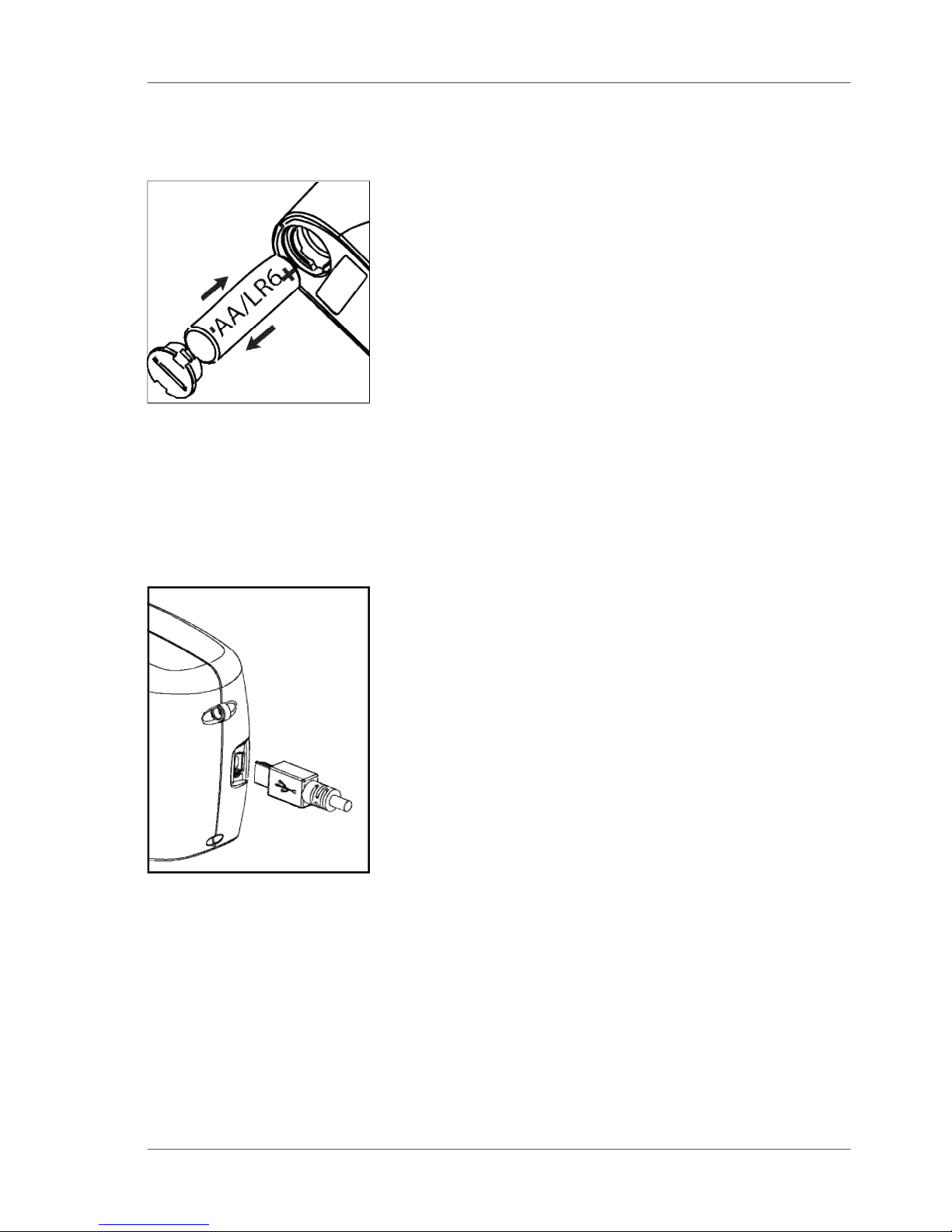
5.1 Power supply battery-operated
The battery must be placed in the measuring unit for
operation service. The device runs on one AA 1.5-V
alkaline or 1.2-V NiMH rechargeable battery.
Use only alkaline batteries or NiMH
rechargeables (AA /LR6)!
Depending on the exact brand, the capacity of each
battery is sufficient for about 4.000 measurements.
When the battery voltage falls below the required
minimum voltage in the course of operation, the
following message appears on the display
Battery low!
To ensure that the unit is always ready for operation,
it is recommended to have a spare battery handy,
especially when performing measurements in the
field.
Page 16
15
Power supply
5.2 Changing the battery
To insert or change the battery open the battery
compartment. The easiest way to do this is by
turning the cover with a coin one-eighth of a rotation
to the left. Turn the device back around and allow
the old battery and the battery compartment cover
to slide into your hand.
Insert the new battery with the positive (top) end first
into the battery compartment and set the battery
compartment cover in place again. Lock the cover
by turning it one-eighth of a rotation to the right.
5.3 External power supply
The instrument can be operated and supplied at a
computer via USB-port. For the connection to the
PC use the USB- cable included in the delivery.
Please refer to the chapter Interface for installation
of the required software and drivers.
For power supply specification note the technical
data.
Changing the battery
Page 17
16
Controls
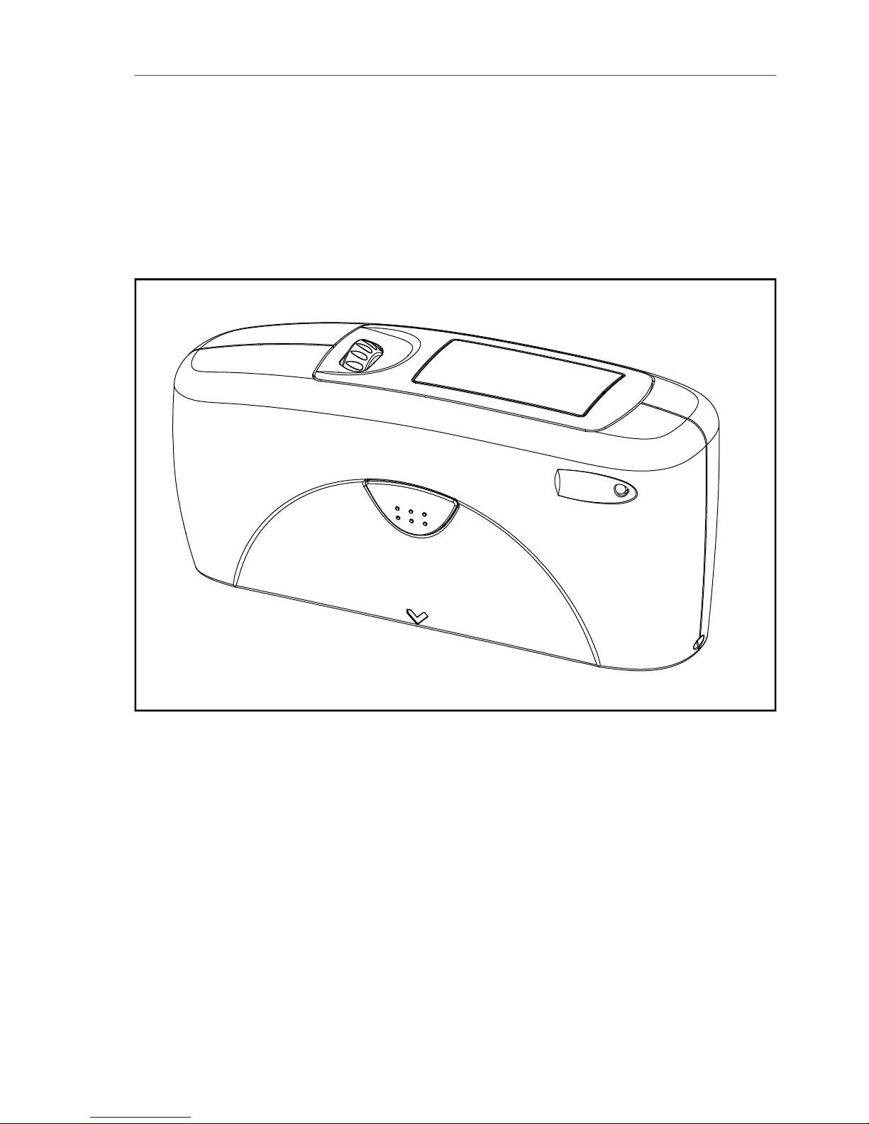
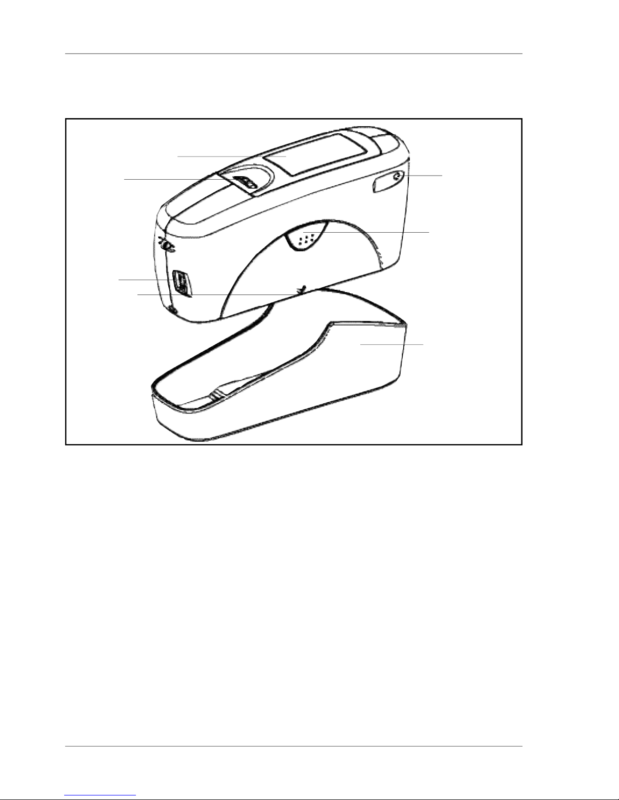
Measurement unit and protective holder
1 Mode scroll wheel: used to turn the unit on and for menu selection
2 Display for user guidance and displaying measurement values
3 Signal lamp:
green: measurement active
red: error
4 Operate button: used to activate measurements
5 Protective holder with integrated calibration standard
6 Mark for the measurement aperture
7 USB interface for connecting to a PC
1
2
4
3
6
7
5
6. Controls
Page 18

17
Controls
The basic system consists of the measuring device
and the protective holder.
The protective holder is used for calibration and to
store the measurement unit. Calibration is
performed inside the holder automatically at the
touch of a button. The gloss standard required for
this purpose is kept in the holder and is positioned
in such a manner that calibration is always
performed at the same point.
When the device is turned on inside the holder, it
performs a self-test (autodiagnosis).
If you will not be using the measuring unit, please
store it in the protective holder. In this way the
measurement optics are protected from dirt and
dust and the calibration standard is always readily
available.
The operate button and scroll wheel are used to
control the system. Pressing the wheel turns the
unit on and causes a menu to be displayed. All
settings within the menus are made by turning and
pressing the wheel.
Pressing the operate button starts measurements or
performs functions that are displayed. In addition,
you can return from the various menus to mode with
the operate button. System operation is supported
by an autodiagnosis test, comments and error
messages. Measurement values and comments
appear in the display.
Page 19

18
Getting started
7. Getting started
7.1 Turning on the unit and measuring
To turn on the unit, press the mode scroll wheel.
Information on the date and last certification appears
in the display. If the device was turned on in its
holder, the autodiagnosis test is performed (see the
section on Calibration).
Then the unit switches into the last measurement
mode to be selected.
Pressing operate initiates measurements.
The display of measurement results on the screen
may be broken down into the following elements:
A: When Difference measurement is turned on,
the name of the standard that is selected is
displayed here.
B: If Memory is selected, the memory area that
is selected appears at the top left and for
C: the sample name (block name).
D: If Statistics or Continuous is turned on, the
number of measurements performed or selected is
displayed here.
The measurement values appear in the lower part of
the display area. The size of the numbers depends
on whether Statistics or Difference measurement
has been activated and on the number of geometries
displayed. Depending on the measurement mode, a
header line also appears for the measurement
values.
Page 20

19
Getting started
7.2 Navigation
All control functions are controlled by the mode
scroll wheel. Pressing the wheel causes a menu to
appear in the display. Turning the wheel allows you
to move the black mark to the desired function and
to select or activate it by pressing the wheel.
What functions are displayed in the menu depends
on the settings in the main menu. The main menu is
the “central” level and can always be reached
quickly.
Certain rules apply within the menus to make it
easier to navigate:
A black triangle to the right of a function indicates
that selecting this function will take you to a submenu.
A check mark on the right indicates that the function
in question has been activated.
You can use the arrow at the top right to switch the
display back by one level.
Arrows pointing up or down indicate that there are
other menu options above or below the part of the
menu that is visible. To reach these menu options,
simply turn the scroll wheel in the direction in which
the arrow is pointing.
You can quickly switch back from the menus to the
measurement display by using the operate button.
In some cases this button also has another
function, but that will be indicated in the display (for
example Confirm -> operate).
Page 21

20
Getting started
7.3 Change names/numbers
For some functions, you can enter or change the
date or name. The arrow pointing upward marks the
position that can be changed. To change the
character, turn the scroll wheel. When you press the
wheel, the arrow jumps to the next character.
After you have adjusted the last character or
number, confirm your input by pressing the wheel.
When you enter the name, the arrow jumps to the
first character. This allows you to correct any
inadvertent incorrect entries. You can confirm the
name in these menus at any time with the operate
key.
Page 22

21
Getting started
Measurement without statistical evaluation.
Multiple measurement with statistics.
Continuous measuring with adjustable interval.
Measuring without statistics, saving and difference.
Reactivates all menues and functions when Basic
mode was activated.
Memory functions:
Turn saving on/off.
Select memory area from list.
Enter up to 50 memory areas.
Delete memory content or memory name.
Recall of memory content (use scroll wheel).
Settings for difference mode:
Turn difference measurement on/off.
Measure a standard.
Select standard (if saved).
Enter up to 50 standards and limits for Pass/Fail.
Delete individual standards.
Enter/change limit values for Pass/Fail.
The following can be used together simultaneously:
Mode
Sample mode
Statistics
Continous
Basic mode
Advanced mode
Geometry
Memory
Memory
Select memory
Create memory
Delete memory
Display memory
Difference
Difference
Measure standard
Select standard
Create standard
Delete standard
Changestandard
Calibration
Setup
Calibrate, change cal. values, GU - % scale.
Date/Time, Beeper, Display time, Language, Info
7.4 Overview of main menu
Select geometry.
• Memory with: Sample mode, Statistics, Continuous
• Difference with: Sample mode, Statistics
Page 23

22
Calibrate
8. Calibrate
The holder with the integrated glass standard is
used for calibration. Always keep the measurement
unit in the holder. This protects the measurement
optics and ensures that the standard is always at
hand.
If you have several devices of this type, you must
put the unit in the holder which belongs to the unit
(see the serial number).
Make certain that the standard is clean and
there are no cracks on it.
When you place the device in the holder, make
certain that it ships firmly into place.
8.1 Autodiagnosis
Whenever you turn on the device in the holder, it first
performs a self-test. During this test, any changes in
the measurement signal are tested against saved
calibration data. This allows for a long-term calibration
so that a new calibration is required only about once a
week. Beyond that, calibration is only necessary if
there are significant weather changes (see under 8.2).
It is recommended that you perform the self-test in the
holder regularly (every day).
The autodiagnosis generally takes about 2 seconds.
“Please clean standard” or “Please test standard”
may be displayed. For more information on
cleaning, see Chapter 20.
A message will appear in the display informing you
that the autodiagnosis has been completed
successfully.
In some cases, the system may suggest that you
repeat the calibration. The reason for this may be
changed ambient conditions. It is also possible,
however, that the standard still has small amounts
of residue left over from cleaning. This problem can
generally be alleviated by cleaning with a dry optical
cleaning cloth.
Page 24

23
Calibrate
8.2 Calibrate
You should recalibrate the device if ambient
conditions have changed. This applies especially
when changing location if major changes in
temperature and relative humidity may be expected
as a result (for example inside/outside).
When moving from cold areas to warm areas, there
is a danger of condensation. For this reason, after
there has been a change in ambient conditions, you
should wait for an appropriate amount of time to
allow the optical components to adjust before
calibrating and using the unit.
Use the path shown on the left side to reach the
Calibrate menu option.
8.2.1 Gloss
To begin calibration, press the scroll wheel.
The calibration process is performed automatically
for all three geometries. The saved calibration values
of the standard appear in the display.
The unit then returns to the selection menu
Calibration.
Page 25

24
8.2.2 Change cal.values
The gloss values of the calibration standard in the
holder included with delivery are saved in the
measuring device. During automatic calibration, this
data is assigned to the standard in the holder.
In some cases it will be necessary to enter data for
a new calibration standard, for example if the
previous standard has been damaged or scratched.
To ensure exact calibration, only original
standards from the manufacturer should be
used.
You can use the path shown on the right side to
reach the Change cal.values menu option.
At three angle units, a selection menu will appear
for geometries. Select the desired geometry and
press the scroll wheel.
A warning message appears. You can cancel this
process by pressing the operate button.
If you press the scroll wheel, you will continue with
the process of changing calibration values.
In the next display you can enter new calibration
values.
Calibrate
Page 26

25
8.2.4 Scale Gloss
You can use the Scale menu option to switch back
and forth between Gloss Units and Reflectance (see
the Section on Practical measuring suggestions).
Move the mark to the desired entry and press mode.
A check mark identifies the Scale that is selected.
After you switch the Scale, the unit must not be
recalibrated.
Calibrate
After you have entered the new value, a warning
message appears again in the display. You can
again abort the process with operate.
If you confirm the new value by pressing the scroll
wheel, the value will be accepted.
After you have changed all necessary values, you
should recalibrate the measurement device as
usual.
8.2.3 Status
This menu item provides you with information on the
calibration status of the unit.
In particular, you can check here whether the saved
calibration values match those of the holder. The
display also indicates if an error message was
generated as a result of the last autodiagnosis or
calibration. If this has happened, further information
is available under Section Errors and warning
messages.
Page 27

26
Calibrate
8.3 Calibrating standards
To ensure exact calibration, only original standards
from the manufacturer should be used.
These are calibrated against tested primary
standards. Their surface must not be touched and
must be protected against scratches. Due to
environmental influences, however, the values of
standards can change over the course of time even
if they are handled gently. For this reason, you
should have the calibration standards tested by the
manufacturer at regular intervals (we recommend
annually).
8.4 Checking standard
We recommend the regular use of a separate test
standard for control of test equipment. The
frequency of this verification depends on the
conditions of usage (for example monthly). The
gloss standards are integrated into an aluminum
guide in which the measurement device is
positioned exactly. Perform the measurement as
you would normally, for example in Basic mode. The
displayed measurement value must not deviate from
the value printed on the standard by more than one
unit. Otherwise you should check whether there is
dirt and dust on the high gloss standard in the
holder or test standard. If cleaning and recalibration
do not offer any improvement, please get in touch
with our Customer Service.
Page 28

27
Measurement techniques
9. Measurement techniques
In accordance with the standard, the reflectometer
value is related to a black glass standard at a
defined index of refraction (generally 1.567) which is
thus equal to 100 units.
Reflectometers are differentiated by the angle of
incidence of the illuminating mechanism.
Geometries are set in the standards at 20°, 60° and
85°.
9.1 Paints and varnishes, plastics and similar materials
The various geometries are distinguished according
to their fields of application as follows:
Semi-gloss surfaces are measured at an angle of
incidence of 60° and should fall within a range from
10 to 70 gloss units.
Highly reflective surfaces with measurement values
exceeding 70 units in the 60° geometry should be
measured at 20°.
On the other hand, matte surfaces with less than 10
gloss units (at 60°) should be measured at the 85°
geometry.
Page 29

28
Measurement techniques
9.2 Anodized aluminum and other metal surfaces
The measuring unit is equipped with an extended
measuring range for measuring samples with a very
high reflectance.
The reflectance of non-metallic surfaces increases
with the angle of incidence. The reflective properties of
metals do not always behave in this manner. Because
of double reflection, the light is partially reflected on
the coating and partially on the metal underneath. For
a complete understanding of the reflective properties
of such surfaces, it is recommended to measure them
at all geometries.
In addition to the reference to a black glass standard
(gloss units), it is also common in the area of metals
to relate the reflectometer value to the amount of
irradiated light and to express it as a % (reflectance).
You can select this in the Scale menu.
Notes
Proper measurements are only possible on level
surfaces.
Measurements on dirty, scratched or otherwise
distorted areas of the test specimen are not meaningful except as a way of determining the degree of such
imperfections by means of a gloss measurement.
Since it cannot be assumed that the gloss capacity is
not constant over the entire surface of the test
specimen, the reflectometer value can be measured
at several different places and the standard deviation
can be determined.
If the sample exhibits structures or directionally
dependent gloss properties, the structural features
and the direction of the incident light should be
specified for the measurement in the test report.
Samples that must be measured several times over
the course of an examination (for example weathering
samples) should be marked accordingly to ensure
that the measurement is made at the same point
during repeated tests.
Page 30

29
10. Measurement Modes
You can select different types of measurement in
the Mode menu. The mode that is activated is
identified by a check mark.
10.1 Sample mode
Single measurements can be performed without
statistical evaluation in Sample mode.
The results can be saved and compared with a
standard (refer to Memory or Difference).
When Memory is turned on, a name is suggested
after every measurement. You can confirm this
name directly or change it.
If you would like to delete the last measurement,
press the scroll wheel and select the appropriate
menu item.
Measurement Modes
Page 31

30
10.2 Statistics
You can make multiple measurements with each
sample in Statistics mode. These measurements
will be evaluated statistically and displayed.
The results can be saved and compared with a
standard. These functions must be previously
activated (refer to Memory or Difference).
Measurement Modes
When Memory is turned on, a name is suggested
after all measurements of a sample (block). You can
confirm this name directly or change it.
When the Statistics function is turned on, additional
functions are available depending on the context
after you press the scroll wheel.
Page 32

31
Measurement Modes
10.2.1Number of measurements
You can adjust the number of measurements per
sample or per block with this option, from 2 - 99.
You can find this value in the measurement display
by looking for “n=” after the forward slash. The
number of measurements (which increases by one
each time a measurement is performed) appears
before the slash.
10.2.2Display
In the Statistics measurement display, you can
assign the following data freely to three columns:
Value:
Last value to be measured
Mean value:
Arithmetic mean of the sample (block).
Maximum:
Highest measurement value of the sample
Minimum:
Lowest measurement value of the sample
Range:
The difference between the maximum and minimum
value.
Page 33

32
Measurement Modes
Std. Dev.:
The standard deviation of the sample
Difference*:
The difference between the sample and a target
value.
Pass/Fail*:
Pass is displayed if the sample value falls within the
specified limits, or Fail if it falls outside.
Off:
Turns off the display of the selected column.
* To be able to use these functions, a standard must
be measured, created or selected. In particular, a
limit value must be defined.
Page 34

33
Measurement Modes
10.2.3Exit block
This function terminates the block before it reaches
the required number of measurements n. It is useful
if you have selected a high number of
measurements for n, for example in the case of
large samples.
If Save is turned on, a display appears to enter a
block name for the sample.
10.2.4Delete block
This function deletes the current block.
10.2.5Delete measurement
This function deletes the last measurement value.
Page 35

34
Measurement Modes
10.3 Continuous
You can use this function to perform up to 99
measurements at an adjustable measurement
interval. This is helpful when you are covering large
samples and you want to evaluate the homogeneity
of the surface.
Activate Continuous under Mode from the Main
menu.
A screen appears for starting a new sequence.
To start the measurement, press operate. The unit
now performs measurements up to 99 times at the
set interval. Measurement values are shown in the
display after each measurement.
You can interrupt the continuous measurement by
pressing the operate button (hold it down briefly).
The number of measurements, the mean value, the
minimum and the maximum appear in the display.
The Pause symbol on the left side indicates that
you can continue the sequence, therefore press the
operate button.
To end the sequence, press mode.
For starting a new sequence, press operate again
If saving is activated, a screen appears at start of a
new sequence, which allows to enter a sample
name.
Page 36

35
Measurement Modes
The measuring interval can be changed before a
sequence is started. Therefore press the mode
wheel to open the Continuous submenu.
The longest measurement interval possible is 9
seconds, the shortest 0 seconds for continous
measuring.
10.4 Basic mode
The selection options are limited to the most
essential in Basic mode. This also greatly simplifies
operation in this mode.
You can select geometry and perform calibration. In
addition, all functions in the Setup menu item are
available.
Basic mode is useful if you want to interrupt a
series of measurements and quickly perform some
other measurements in the middle without leaving
the series of measurements.
Once these other measurements are complete, you
can use
to return to the point where you interrupted the
series of measurements.
Page 37

36
11 Geometry
In this menu, you can select the geometry for the
gloss measurement.
11.1 Geometry selection
Choose Gloss Geometry from the Geometry menu.
You can choose between the representation of one,
two or all three geometries in the display.
The currently set angle combination is indicated in
the Geometry menu by a check mark.
Select the desired combination with the scroll wheel
and then confirm by pressing mode.
When Save is turned on, switching the geometry
automatically causes the program to switch to the
appropriate predefined area of memory.
Geometry
Page 38

37
12. Memory
To save measurement values, you must activate the
Memory function before measuring or else select or
create a memory. Up to 999 measurements can be
stored. A fixed memory area is already created for
each geometry or combination (e.g. M60°). These
memory areas cannot be deleted. A total of 50
memory areas can be created.
The Memory function can be used for sample mode,
Statistics and Continuous measurements. The
layout of the memory is such that the measurement
mode and the standard can be changed within a
memory area, but not the geometry.
12.1 Memory
You can use this function to turn saving on or off. A
check mark indicates if the function has been
activated.
Turning on Memory automatically selects the area
in memory that is predefined for the currently set
geometry (for example M20°60°).
When you press operate to start a reading, you are
asked to enter a name for this memory.
12.2 Select memory
All available areas of memory are listed in this
menu, beginning with the one that is predefined.
The number of measurements saved for each area in
memory is shown on the right.
Select the appropriate memory area with the scroll
wheel and activate the selection by pressing mode.
This automatically turns on Save and switches the
geometry if necessary (if the selected memory area
is defined for other geometries than what was
previously set).
Memory
Page 39

38
12.3 Create memory
Users can set up their own memory areas with this
function. Select the required geometry before you
activate this function. Then you must enter the
name of a memory area. You can confirm the
suggested name directly with the operate button or
change it with the scroll wheel. After you confirm,
Save is automatically turned on.
12.4 Delete memory
This menu lists all memory areas that have been
created with the number of values stored in each
one.
Use the scroll wheel to move the mark to the
memory area you would like to delete and press the
wheel.
A menu appears in which you can decide whether
you would like to delete just the content of the
memory area or the entire memory area.
For pre-defined memory areas, you can only delete
the measurement values.
12.5 Display memory
You can transfer data that has been saved to a PC
via the interface. The values can also be shown in
the display at any time.
The “Display memory” function opens a menu in
which all memory areas that have been created are
listed. Select the desired area of memory with the
scroll wheel.
Memory
Page 40

39
Memory
The values of the first measurement appear in the
display. The sample name is displayed in the
highlighted field.
Turning the wheel switches the display to the next
sample with its corresponding values.
Which values are displayed in the columns (for
example mean value, min., max.) depends on the
display currently selected for Statistics.
Page 41

40
Difference measurement and Pass/Fail
13. Difference measurement and Pass/Fail
You can compare the readings of samples with the
value of a previously measured or saved standard.
For saved standards, you can also display whether
the test specimen falls within the limits (Pass) or
outside (Fail).
Up to 50 standards can be saved. They are stored in
a separate area of memory. For each geometry you
can determine:
- A target value
- Maximum and minimum for Pass/Fail,
see Create standard or Change standard.
13.1 Difference
You can use this menu option to turn Difference
measurement on or off. A check mark indicates if
the function is active.
When you turn on Difference, the last standard to be
used is automatically selected.
If no standard is available, choose the function
“Measure standard“ or “Create standard“ to
continue.
13.2 Measure standard
We recommend to perform several readings on the
standard with Statistics turned on.
Memory must be activated to store the measured
standard. Otherwise it will be temporary hold until
another standard is measured.
Activate “Measure standard” and perform the
measurement with operate. With memory on, a
window appears after the last reading where you can
enter the standard’s name.
If you inadvertently select a name that has already
been used, a message will appear in the display
and the arrow will jump back to the first position of
the name.
Page 42

41
The measured standard values are saved as the
target values. At the same time, Difference
measurement is turned on and the measured
standard is activated. If you want to define limit
values additionally , you can use the “Change
standard” function.
For measuring the samples continue by pressing
operate. The display shows the sample values and
difference to the target.
The Measure standard function can also be reached
directly from the measurement screen by pressing
mode.
If you want to compare samples without saving the
standard, use the Difference mode with Memory
switched off. A measured standard will be kept
temporary then, until you measure another one.
13.3 Select standard
To select an existing standard, use the arrow to
move the mark to Select standard and then press
the wheel.
The first standard appears in the display. The target
value, minimum and maximum are displayed. For
values that are not defined, 0.0 or 2000 is displayed.
The name of the standard appears inverted at the
top right.
Turning the scroll wheel causes the next standard to
be displayed.
When you have selected the desired standard in the
display, activate it by pressing on the wheel.
A reference to the selected data will appear in the
display.
To start Difference measurement press “operate“.
Difference measurement and Pass/Fail
Page 43

42
Difference measurement and Pass/Fail
13.4 Create standard
Standards can also be saved by entering the target
and limit values with the scroll wheel. Move the
mark to “Create standard” and activate the function.
A display appears in which you must assign a name
for the new standard. If you inadvertently select a
name that has already been used, a message will
appear to this effect and the marker arrow will jump
back to the first position of the name. Confirm the
name with the operate button.
In the next step you can define the target and limit
values of your standard.
Define standard
With the three angle device, a menu first appears in
which you can select the geometry.
After that, the menu appears for selecting the target
value, minimum and maximum.
Select the desired variable and press on the scroll
wheel.
Now you can adjust the corresponding value.
After the last number is activated, the display jumps
back to the previous menu.
In this manner you can enter additional target and/or
limit values for the standard one after the other if
need be. After the entries are complete, Difference
measurement is turned on with the new standard.
Page 44

43
Difference measurement and Pass/Fail
13.5 Change standard
You can use this function to change target values
and limit values of saved standards. You can also
use it to define limit values subsequently (for
example for a measured standard). Use the scroll
wheel to move the mark to Change standard and
press the wheel.
All standards are listed one after the other in the
following menu. Select the desired standard and
press the scroll wheel.
In the next step you can define the target and limit
values as described above.
13.6 Delete standard
Use the selection wheel to move the mark to Delete
standard in the Difference menu and then press the
wheel.
The Delete standard menu appears. All saved
standards are listed in this menu.
If there are more standards than can be shown in
the display, arrows on the right edge of the display
will point to additional standards.
Use the scroll wheel to move the mark to the
desired standard and press the wheel.
The standard to be deleted is listed again in the
display. Confirm by pressing the mode scroll wheel.
The unit then reverts to the previous menu.
Page 45

44
14. Setup
You can make general settings in the Setup menu,
for example Language or Display time.
14.2 Date/Time
The unit contains an integrated clock. This makes
the date and time of the measurement available for
data transfer to a PC. The date and time are not lost
even when the battery is changed. If you would like
to change the time setting, use the scroll wheel to
move the mark to Date/Time and then press mode.
The display for setting the date and time appears.
14.3 Beeper
You can use this menu option to turn the beeper on
or off. Use the scroll wheel to move the mark to
Beeper and press the wheel.
When the beeper is turned on, a check mark
appears at the end of the line.
14.4 Display time
To save electricity, the unit automatically turns off
after a certain amount of time. You can determine
this time yourself with Display time.
Setup
Page 46

45
Setup
14.5 Language
You can use this menu to select the display
language.
Use the scroll wheel to move the mark to the
desired language and press the wheel.
14.6 Info
You can use this menu option to find the following
information:
• Catalog No.
• Serial No.
• Version number of the firmware
• Date of the last calibration
• Date of the last certification
Page 47

46
Interface
15. Interface
The measurement device is equipped with a USB
interface that allows direct communication with a
PC.
For data transfer use the USB cable included with
delivery. Measurement data can be transferred into
the gloss software, which is available for download
from the support section of the instrument suppliers
website. The data are displayed immedeately in a
test report with trend graph.
Page 48

47
Standards
16. Standards
ISO 2813 Paints and varnishes - Determination of specular
gloss of non-metallic paint films at 20°, 60° and 85°
ASTM D 523 Standard Test Method for Specular Gloss
ASTM D 2457 Standard Test Method for Specular Gloss of Plastic
Films and Solid Plastics
DIN 67530 Reflektometer als Hilfsmittel zur Glanzbeurteilung an
ebenen Anstrich- und Kunststoffoberflächen
(Reflectometer as a means for gloss assessment of
plane surfaces of paint coatings and plastics)
JIS Z 8741 Method of Measurement for Specular Glossiness
ISO 7668 Anodized aluminium and aluminium alloys -
Measurement of specular reflectance and specular
gloss at angles of 20°, 45°, 60° or 85°.
Page 49

48
Specifications
17. Specifications
Model MULTI GLOSS 268A UNI GLOSS 60A
UNI GLOSS 60CT
UNI GLOSS 60S
Measurement geometry 20°, 60°, 85° 60°
Size of measurement 20°: 10 x 10mm 60°A, CT: 9 x 15mm
spot 60°: 9 x 15mm 60°S: 2 x 4mm
85°: 5 x 38mm
Standard compliance ISO 2813, ASTM D 523, ASTM D 2457, DIN 67 530
and ISO 7668, JIS Z 8741 (excluding 60° S)
Measurement range 20°: 0.0 ~2,000 GU
60°: 0.0 ~1,000 GU 60°: 0.0 ~1,000 GU
85°: 0.0 ~ 160 GU
Resolution 0 ~99.9 GU: 0.1 GU100~2 000 GU: 1 GU
Repeatability 0.0~99.9 GU: 0.2 GU
100~2,000 GU: 0.2% of reading
60°CT: 0~19.9 GU: 0.1 GU
Inter-instrument 0.0~99.9 GU: 0.5 GU100~2,000 GU: 0.5% of reading
agreement 60°CT: 0~19.9 GU: 0.2 GU
Memory 999 measurements with date and time
Difference measurement Memory for 50 standards
Battery performance Approx. 4,000 measurements (when using 1.5 V
AA(R6) size alkaline battery)
Measurement time 0.5 seconds / geometry
Auto power off 10~99 seconds selectable
Languages English, Spanish, German, French, Italian,
Japanese, Russian, Polish, Portuguese, Turkish
Measurement mode Normal mode (Sample mode, Statistics,
Continuous, Basic mode), Difference mode
Interface USB 2.0
Operation temperature/ 15 to 40°C relative humidity max. 85% (at 35°C)
humidity range with no condensation
Storage temperature/ -10 to 60°Crelative humidity max. 85% (at 35°C)
humidity range with no condensation
Power 1.5 V AA(R6) size alkaline battery, or via USB-port of PC
Size 155(W) × 73(H) × 48(D) mm
Weight 400 g
Page 50

49
18. Accessories
Model MULTI GLOSS 268A UNI GLOSS 60A
UNI GLOSS 60CT
UNI GLOSS 60S
Standard accessories Calibration holder TRI Calibration holder 60°A
(High gloss tile) Calibration holder 60°CT
Calibration holder 60°S
(High gloss tile)
USB-cable
Carrying case
Gloss Data Software
(Downloadable from internet; 2 licenses)
1.5 V AA(R6) size alkaline battery
Optional accessories Checking standard TRI Checking standard 60°A
(High and 3 semi gloss tiles
Checking standard 60°CT
20, 60, 85°)
Checking standard 60°S
(High and semi gloss tile)
Checking standard Mirror
(
High and
3
semi gloss
tiles 20, 60, 85°)
Note: The accessories described in this document are subject to change without notice.
Accessories
Page 51

50
Errors and warning messages
19. Errors and warning messages
Memory full Transfer the content of memory to a PC and then
delete the contents of memory.
Reference memory full A maximum of 50 references can be saved. It may
be necessary to delete old references.
You will also find an error number for the following messages in the Calibration/
Status menu to provide support for diagnostics:
Tolerance Generally occurs only with major changes in
Error 01 climatic or weather conditions. The deviation was
successfullycompensated for by calibration and
correct measurements are still possible. You should
still recalibrate the device as soon as it is operating
in normal climatic conditions again. However if a
change in climate cannot be considered as the
cause of the problem, you should check whether the
standard is clean.
Please call Service Autodiagnosis has determined an impermissible
Service (invalid) deviation in the measurement signal
that cannot be remedied by recalibrating.
Error 02 Generally occurs when there is a significant amount
of dirt or dust on the standard or optics. First try to
clean the standard. You should only have the optics
cleaned by our Customer Service department, for
example as part of a yearly recertification.
Error 03 Defect in the electronics or operating error. First
check whether the standard is clean and whether
the device is properly snapped into the holder.
Error 04 Defect in the lamp or electronics.
Error 05 Defect in the electronics.
Please observe the instructions on cleaning standards in the section on
Calibration.
Page 52

51
Errors and warning messages
Fluctuations in measurement values
Was the same point on
the sample used for all
measurements?
Yes. It may help to test
the calibration with an
additional standard if
one is available.
Calibration correct:
Is the test surface
completely even and
does the measuring
device have good
contact with the
sample?
Yes: Device defective
No. Check how high the deviations are on
the sample itself.
Calibration not correct:
Recalibrate and clean the standard if
necessary.
No:
In this case, major deviations are possible.
Please contact our Customer Service
department.
Do not attempt to make any repairs yourself! If a malfunction occurs on your
measuring device, our Customer Service department will be happy to help you
as quickly as possible.
Page 53

52
20. Cleaning and maintenance
• Do not insert any objects into the measurement
aperture for cleaning. The instrument could get
damaged - affecting a proper and safe operation.
• The instrument housing is resistant to a number
of solvents, but cannot be guaranteed to withstand
all chemicals. You should therefore use a soft,
moist cloth for cleaning. For cleaning excessive dirt,
use ethanol or cleaning alcohol. Do not use any
acetone!
• Cleaning standards
The accuracy of the measurement can be
significantly impacted by using dirty or damaged
standards.
Since the surfaces of the standards are highly
sensitive, cleaning must be undertaken with great
care.
To clean standards, use a new lint-free cloth, dust-
free lens paper or an optical cloth.
Apply only slight pressure as you clean and make
certain there are no large particles stuck in the cloth
that could damage the surface. Do not use any
acetone!
For dirt that is difficult to remove, use an optical
cloth dipped in liquid. Then wipe the surface with a
dry optical cloth.
Exact calibration is not possible unless the
standard is in perfect condition. If the condition of
the standard seems doubtful
because of its appearance or measurement errors,
we will be happy to check it for you.
Cleaning and maintenance
Page 54

53
21. Copyright
Copyright
Page 55

260 023 933 E 1609
 Loading...