

Page 1
ILLUMINANCE METER LUMINANCE METER CHROMA METER
T-10A / T-10MA / T-10WSA / T-10WLA
CL-200A
CL-500A
LS-100/ LS-110
CS-100A
CS-200
Page 2
illuminance Measurement Trio
Illuminance Meter
T-10A series
Cross-sectionA
Height (m)
illuminance(lx)
300
100
50
30
3
4
10
5
0011223
-1-2-3
Compatible with new, next-generation light sources including PWM-controlled sources.
For simple but accurate illuminance measurements. Makes creating illuminance
measurement systems such as multi-point measurement systems easy!
<Mini receptor ><Standard receptor>
T-10A T-10MA / T-10WSA / T-10WLA
Receptor
diffuser
window:
Ø 25 mm
Main Features
Reliable, worry-free illuminance meters that
conform to JIS AA Class and DIN Class B
Illuminance Meters T-10A and T-10MA conform to Class AA of JIS
C 1609-1: 2006 "Illuminance meters Part 1: General measuring
instruments" and DIN 5032 Part 7 Class-B " Photometry;
classication of illuminance meters and luminance meters"
requirements to provide high-accuracy, high-reliability, worry-free
measurements.
Illuminance meters conforming to these standards are required for
measurements of general illumination light sources, white LED lamps
for illumination, etc. in a variety of industrial elds.
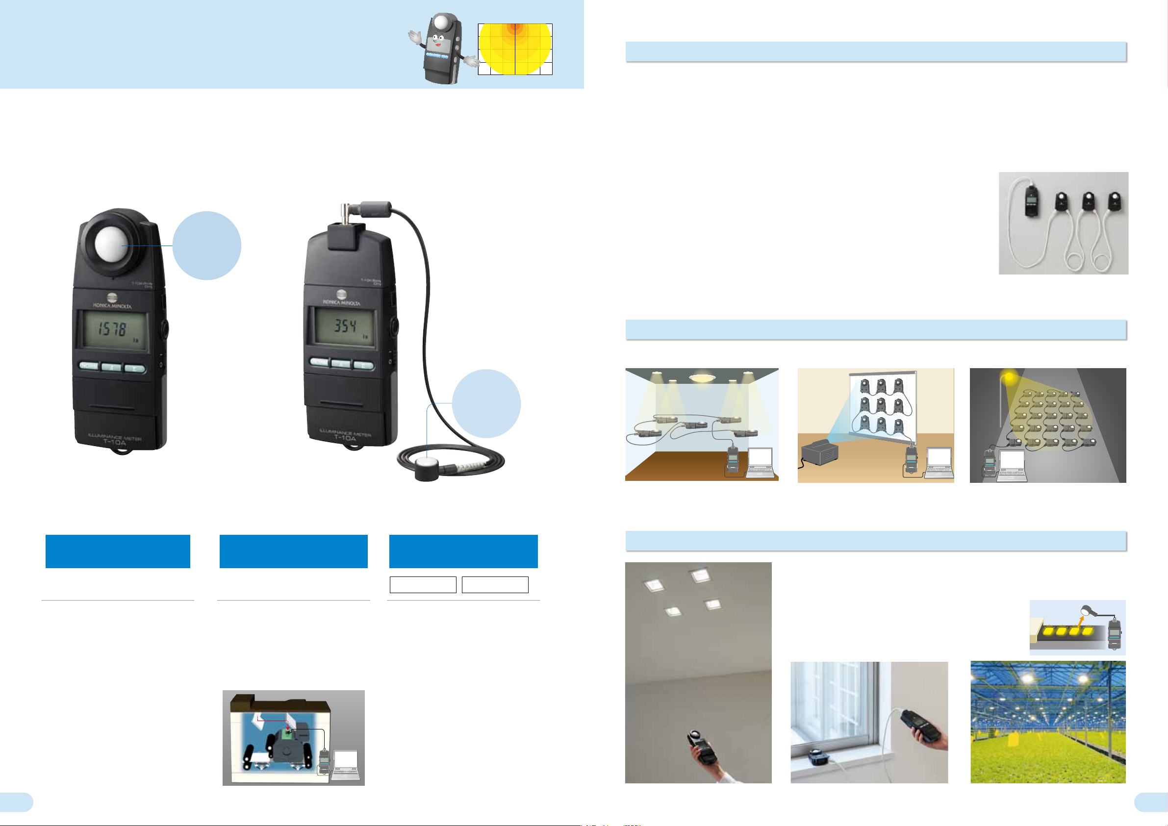
Easy, inexpensive multi-point measurement
(2 to 30 points).
Illuminance distribution of a projector etc. can be easily
measured with a single instrument and several receptors.
Compatible with PWM-controlled lighting. Enables
measurements of next-generation light sources.
Conventional illuminance meters often cannot accurately
measure PWM-controlled light sources, but the T-10A series
of illuminance meters can be used to accurately measure
even such light sources.
Removable receptor
The receptor and main body
can be detached from each
other and then connected
using a LAN cable, making it
easy to install as part of an
inspection system.
T-10A
Conforms to JIS AA Class
and DIN class B
Can be used for general
measurements of illuminance.
T-10MA
(Cord length: 1 m)
Conforms to JIS AA Class
and DIN class B
Enables illuminance
measurements of small areas.
Can be used for illuminance
measurements in narrow spaces
where the standard receptor won't t.
It can also be easily installed on
various kinds of equipment or jigs
for measuring light levels such as
illumination.
Receptor
diffuser
window:
Ø 14 mm
T-10WSA
T-10WLA
(Cord length: 5 m)
(Cord length: 10 m)
Conforms to JIS requirements
for special illuminance meters
Custom orderWaterproof
The mini receptor and cord are both
waterproof, so they can be used for
measurements in water.
They can be used for illuminance
control for shery-related applications
(such as sh farming, etc.) or for
measuring outdoor illuminance on
rainy days.
Multi-point illuminance measuring system
z5-point example: Architectural lighting, etc.
z9-point example: Projectors, etc.
●
Main applications
zGovernment testing organizations
zResearch/inspection at illumination
equipment makers
zMaintenance at factories, ofces, hospitals,
etc.
zIlluminance control of security lighting,
street lighting, etc.
z25-point example: Street lighting, etc.
zChecking light sources for construction
zLighting control at LED-lit factory farms
zAs sensor for equipment measuring total
ux or light-
distribution
characteristics,
etc.
Illuminance Meter T-10A series Illuminance Meter T-10A series
2 3
Page 3
Center of
tripod
socket
Center of
receptor window
7.5
Ø25
35
174
117.5
69
Ø45.2
T-10A
T-10MA/ T-10W
A/T-10WLA
30
Reference
plane
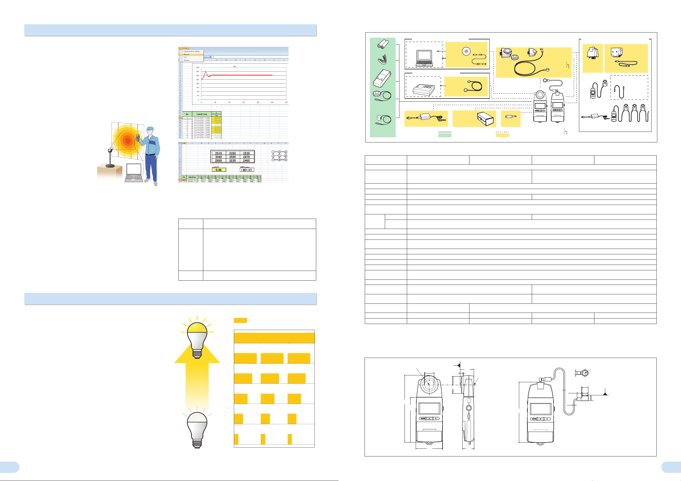
Data Management Software T-S10w (Optional accessory)
Convenient, easy-to-use Excel® add-in software
Reads measurement data from T-10A series Illuminance
Meters directly into Excel
then be performed easily using the various functions of
®
Excel
.
®
. Further processing of data can
Data transfer using buttons on main body
When using T-S10w,
measurements can be taken
and data sent to Excel
®
by using
OK!
not only the computer keys but
also by using the buttons on the
T-10A main body.
PASS
FAIL
Multi-point measurement and CCF calibration
possible
Measurements of up to 30 points can be controlled. A CCF
(Color Correction Factor) function is also provided to enable
calibration to user standards.
PWM is the abbreviation of Pulse Width Modulation, and
refers to the method of controlling signal intensity by
controlling the ratio between the ON period and OFF period
of a pulse signal.
A pulse signal is a signal which repeatedly alternates
between ON and OFF, and the percentage of ON period
during a single cycle is referred to as the "duty cycle".
PWM-controlled lighting is a method for controlling the
brightness of a lamp by controlling the duty cycle (lit time) of
light from a pulse-emission source. As the lit time becomes
longer, the light becomes brighter, and conversely, as the lit
time becomes shorter the light becomes darker.
About PWM-controlled lighting
Main specifications of Data Management
⿎
Software T-S10w
Type Add-in for Excel
Operating
environment
Compatible
instruments
(Excel® is required to use this add-in.)
One of the following environments with Excel
* Languages in parenthesis ( ) are the OS language.
Windows
Chin ese)
Windows
Chin ese)
* For details on system requirements for above versions of
Windows
* Not compatible with 64 -bit versions of ofce 2010.
T-10A, T-10MA, T-10W
T-10W
®
®
installe d:
®
XP + Excel® 2003 (English, Japanese, or Simplied
®
7 + Excel® 2010 (English, Japanese, or Simplied
®
and/or Excel®, refer to their respective specications.
A, T-10WLA, T-10, T-10M,
, T-10W
S
S
L
Period when LED is lit
System diagram
⿎
Data management using computer
Data Management software
T-S10w
(Including
T-A15)
USB Cable
T-A15
AA-size batteries
2 pcs.
Strap
Personal computer
(Commercial product)
Data recording using printer
RS-232C printer
e
Cas
T-A10
Ca
p (with Strap)
T-A13
(for T-10A)
Mi
ni C
ap
T-A14
(for T-10MA)
Main Specications of T-10A
⿎
Model
Type Multi-function digital illuminance meter with detachable receptor head (Multi-point measurements of 2 to 30 points is possible)
Illuminance meter class
Receptor
Relative spectral re spon se
Cosine response (f
Measuring range Auto range (5 manual ranges at the time of analog output)
Measuring function
Measuring
range
User calibration function CCF (Color Correction Factor) setting function: Measurement value x 0.500 to 2.000
Linearity ±2% ±1 digit of displayed value
Temperature/
humidity drift
Computer interface USB
Printer output RS-232C
Analog output 1 mV/digit, 3 V at maximum reading; Output impedance: 10 KΩ; 90% response time: 28 ms
Display 3 or 4 Signicant-digit LCD with backlight illumination (Automatic illumination)
Power source
Battery life 72 hours or longer (when alkaline batteries are used) in continuous measurement
Operating tem per atu re
/humidity range
Storage temperature /
humidity range
Dimensions
Cord length
Weight (without battery) 200 g (7.0 oz.) 205 g 260 g (Receptor head only: 120 g) 3 40 g (Receptor head only: 200 g)
*1 Conforms to requirements for Class AA of JIS C 1609-1: 2006 for all items except cosine response (f2).
*2 Although measurements below 1.00 lx are possible, they may not be stable due to the effects of electric al noise.
<Notes regarding mini receptors and waterproof mini receptors>
*Do not touch the cable during measur ements. Doing so may resul t in unstable measurement values.
*Secure the cable during measurements. Failure to do so may result in unstable measurement values.
⿎
Illuminance 0.01 to 299,900 lx; 0.001 to 29,990 fcd 1.00 to 299,900 lx; 0.1 to 29.990 fcd *
Integrated
illuminance
Dimensions
(Commercial product)
Printer Cable
T-A12
External power
Hard Case
Hard Case
CL-A10
AC Adapter
Standard accessories
<
Illu mi nan c e M ete r T-10A
(Standard receptor head)
Conforms to requirements for Class AA of JIS C 1609-1: 2006 "Illuminance
meters Part 1: General measuring instruments" Conforms to DIN 5032 Part
7 Class B
Silicon photocell
Within 6% (f1´) of the CIE spectral luminous efciency V (λ)
) Within 3% Within 10%
2
Illuminance (lx). illuminance difference (lx). illuminance ratio (%). integrated illuminance (lx·h).
integration time (h). average illuminance (lx).
0.01 to 999,900 x 103 lx·h 0.001 to 99,990 x 103 fcd·h / 0.001 to 9999 h
Within ±3%
2 AA-size batteries / AC adapter AC-A308 (optional; for 1 to 10 receptors) or
AC adapter AC-A311 (optional; for 1 to 30 receptors)
-10 to 40°C, relative humidity 85% or less
(at 35°C) with no condensation
-20 to 55°C, relative humidity 85% or less
(at 35°C) with no condensation
69 x 174 x 35 mm
– 1 m 5 m 10 m
> <
CL-A10
Optional accessories
Illuminance Meter T-10MA
(Mini receptor head)
Main body: 69 x 161.5 x 30 mm
Receptor: Ø16.5 x 13.8 mm
(Units: mm)
Center of
receptor window
174
117.5
Ø25
Reference
plane
Ø45.2
7.5
35
Additional receptors (sold separately; Product
includes 1 receptor according to model purchased)
T-10MA Receptor Head
T-10W
S
A Receptor Head
T-10WLA Receptor Head
Custom order
T-10A
T-10MA
T-10W
T-10W
Illu mi nan c e M ete r T-10W
(Waterpr oof mini receptor head)
Conforms to requirements for special Illuminance meters of JIS C 1609-1:
1
2006 *
5 to 40°C, relative humidity of 85% or less
(at 35°C) with no condensation
0 to 55°C, relative humidity of 85% or less
(at 35°C) with no condensation
Center of
tripod
socket
>
T-10A
Receptor
Head
Mini plug
161.5
S
A
L
A
Custom models
For multi-point and cable extension measurement
Adapter Unit for
Main Body
T-A20
Example of cable
extension
Example of
multi-point System
Multi-point measurement requires use of
optional AC adapter.
A
S
Ø6.5
Ø16.5
Ø14
Ø12.7
Ø3
With LAN category 5 cable; 1m
category 5 straight cable
Illu mi nan c e M ete r T-10WLA
(Waterpr oof mini receptor head)
2
Center of
receptor
window
Reference
plane
13.6〜13.9
Adapter Unit for
Receptor Head
T-A21
LAN (10 BASE-T)
(commercially
available)
Cordlength:
T-10MA ( 1 m)
T-10W
T-10W
69
T-10A
Illuminance Meter T-10A series Illuminance Meter T-10A series
4 5
30
S
SA ( 5 m)
LA (10 m)
Page 4
PASS
FAIL
OK!
y
illuminance Measurement Trio
Chroma Meter
CL-200A
De facto industry standard for measuring
color temperature!
0.90
520
530
0.80
540
510
550
0.70
0.60
500
0.50
0.40
4000
4500
D55
*
D65
*
*
D75
C
*
0.30
490
10000
0.20
480
0.10
470
460
380〜440
450
0.00
0.10 0.20 0.30 0.40 0.50 0.60 0.70
560
570
580
2500
2000
3000
590
3500
*
A
600
1500
B
*
610
680〜780
620
650
x
Measures color
temperature!
Measures dominant
wavelength!
Even measures
excitation purity!
Application examples
Main Features
Compact and easy to carry
The CL-200A's compact body ts in your
palm. Battery-powered so it can be taken
along and used anywhere.
Data transfer using main body buttons
When using the CL-200A
with Data Management
Software CL-S10w
(included), measurements
can be taken and data
transferred to Excel
®
using
the main body buttons as
well as computer keys.
Detachable receptor head
The receptor head can be detached and then connected to
the main body using a normal LAN cable*, making it easy to
install the sensor in an inspection system.
Optional Adapter Units required for receptor head and main body
*
Can also measure illuminance
(JIS AA class)
Excel® add-in software included
Data Management Software CL-S10w
(Standard accessory)
Easy, convenient Excel® add-in
Measurement data from the CL-200A can be transferred
directly into Excel
managed freely within Excel
Includes LED ranking function
Color variations, the top topic in the LED industry, can be
quantied and a ranking function is also provided.
JIS correlated color temperature
Correlated color temperature is determined using the
equations dened by JIS (Japanese Industrial Standards).
Multi-point measurement and user
calibration also possible
Multi-point measurement management using up to 30
receptor heads is possible.
User calibration function enables compensation of
measurement values to match a desired standard.
Calibration can be performed by two methods: Singlepoint calibration or RGB calibration.
®
. The transferred data can then be
®
.
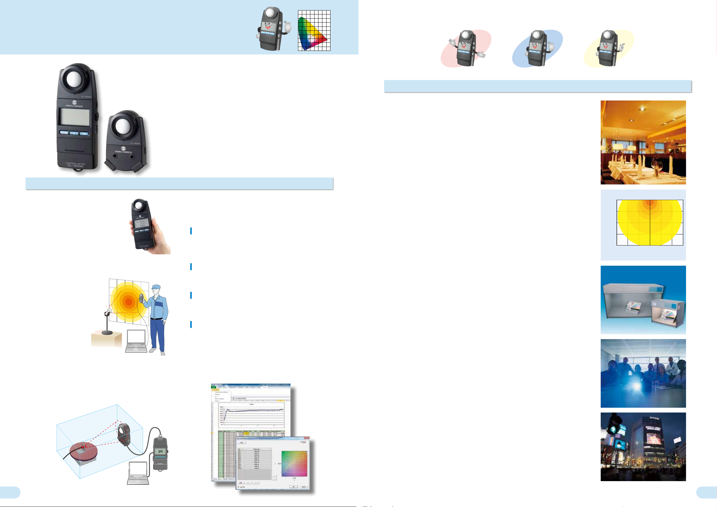
For lighting production and adjustment
When using various types of light sources in a room or open space, it is sometimes
necessary to check the color of the lighting.
By using the CL-200A, it is possible to adjust the lighting color so that the food in a
restaurant looks delicious.
For evaluating light source characteristics
Evaluation of the light distribution of LED illumination modules or the illuminance
distribution of lighting xtures can be evaluated.
For color-viewing cabinet maintenance
A color-viewing cabinet like that shown at left is used in industries such as the
printing industry to visually evaluate nished work under controlled conditions.
This color-viewing cabinet provides illumination at a specic illuminance and color
temperature by using uorescent lamps, halogen lamps, etc. The CL-200A can be
used for the daily maintenance and control of these lamps as well as to indicate when
replacement is needed.
For projector light-source research and color inspection
The CL-200A can be used to measure the white balance and uniformity of
microprojectors, etc. with internal LED light sources. The ability to connect multiple
receptors using LAN cables enables measurement of not only a single point in the
center, but up to a maximum of 30 points over the entire projected area.
Cross-section A
Height (m)
3
4
Illuminance (lx)
300
100
50
30
10
5
0011223
-1-2-3
Horizontal distance (m)
For LED billboard development and maintenance
The CL-200A enables quality control of the LED modules for digital signage to be
performed easily. If modules with different color tones are used together, the billboard
Chroma Meter CL-200A Chroma Meter CL-200A
6 7
PASS
FAIL
will look mottled, but by measuring the chromaticity and color temperature of modules
using the CL-200A and selecting modules based on measured values, billboard
uniformity can be achieved.
Page 5

Reference plane
Center of receptor
Tripod socket
56.318
Reference plane
Center of receptor
window
Tripod socket
7.5
35
69 30
174
φ25
φ45.2
56.318
13
*
Optional receptor head
For multi-point measurement / detached head
y
For accurate measurements of color temperature, use the CL-200A!
Measurement accuracies of CL-200A and photographic color meter
When measuring light sources with non-continuous spectrums such as LEDs, etc., accurate illumination color temperature is
particularly required. The CL-200A can measure color temperature accurately.
CL-200A
The CL-200A has sensors that closely match the color-matching functions dened by the CIE (International Commission on
Illumination), enabling precise color measurement. The measurement results can be displayed in various color notations such
as "Correlated color temperature and
uv" according to the application.
Photographic color meter
In order to take more beautiful pictures, it is sometimes necessary to attach lters in front of the camera lens to compensate for
the color of the light illuminating the subject. A photographic color meter is a meter used to select the appropriate lters, with the
sensitivity of its sensors adjusted to match that of the lm or digital camera sensor. In addition, because it uses photographic
color temperature, which is calculated based mostly on the blue/red balance of the illumination, large errors may occur if it is
used to measure light sources with non-continuous spectrums.
[Actual measurement data for daylight-color LED bulb]
Measured color temperature
Our company's standard instrument
5045 0
CL-200A 5011 -34
Photographic color meter 5600 555
Color-temperature difference from
standard-instrument measured value
Color temperature and correlated color temperature
Color temperature
When an ideal blackbody* is heated, it begins to emit light, and as the temperature increases the color of the emitted light
changes from red to yellow to white. Since the color of the emitted light is determined by the temperature of the blackbody, the
color of the light emitted by the blackbody can be expressed as the absolute temperature of the blackbody (in Kelvin). This color
notation scale is called "color temperature". For example, a 7000 K color would be the color of the light emitted by a blackbody
heated to 7000 K. Figure 1 shows the color of light emitted by a blackbody at various temperatures plotted on an xy chromaticity
diagram. This curve is called the "blackbody locus"; "color temperature" expresses a color on this blackbody locus.
Correlated color temperature
Since the color of white light emitted by illumination equipment and displays is generally close to the blackbody locus, the
color of such light sources is normally expressed using "color temperature".
However, the color of such light sources is not directly on the blackbody locus. Because of this, a way to enable similar
color expression for colors within a larger region close to the blackbody locus was devised. This is called "correlated color
temperature", and the larger region is shown by the isotherms on the xy chromaticity diagram in Figure 2.
To accurately express the correlated
color temperature of a light-source
color, it is necessary to state not only
the correlated color temperature but the
difference from the blackbody locus,
normally in terms of
*Blackbody
An ideal radiator. A body which completely absorbs all
incident electromagnetic radiation. Although a perfect
blackbody does not actually exist, coal is a familiar
object that acts similarly.
0.90
520
uv.
0.80
0.70
0.60
0.50
0.40
0.30
0.20
0.10
0.00
530
510
500
490
480
540
550
D55
D65
D75
380〜440
*
10000
4500
560
570
580
2500
2000
3000
3500
*
4000
A
1500
B
*
*
*
C
*
470
460
450
0.10 0.20 0.30 0.40 0.50 0.60 0.70
590
600
610
0.50
0.45
0.40
6000
7000
8000
9000
10000
13000
15000
20000
0.01uv
0.02uv
0.25 0.30 0.35 0.40 0.45 0.50 0.55
620
650
680〜780
0.35
0.30
30000
50000
0.25
+0.02uv
+0.01uv
0.00uv
0.20
x
2500
3000
3500
4000
4500
5000
Figure 1: Blackbody locus on xy chromaticity diagram Figure 2: Closeup of blackbody locus on xy chromaticity
diagram showing correlated color temperature region
System diagram
⿎
Processing by computer
PC
(commercially
available)
AA Battery (2pcs.)*
Strap
Case T-A10
Cap T-A13
<Standard accessories>
Not included as standard accessory in some areas.
Main specications of Chroma Meter CL-200A
⿎
Model Chroma Meter CL-200A
Luminance meter
class
Relative spectral
response
Cosine response
Receptor Silicon photocell
Measuring
function
Other function
Measuring range
Accuracy*
Repeatability*
Temperature drift Ev: ±3% ±1digit of displayed value, xy: ±0.003
Humidity drift Ev: ±3% ±1digit of displayed value, xy: ±0.003
Response time 0.5 sec. (continuous measurement)
Computer interface
Printer output RS-232C
Display 4-signicant-digit LCD with back-light illumination
Operating temperature/
humidity range
Storage temperature
/ humidity range
Power source
Batter y life
Dimensions
Weight
800 lx, Standard Illuminant A measured
*
Dimensions
⿎
Conforms to requirements for Class AA of JIS C 1609-1: 2006 "Illuminance
meters Part 1: General measuring instruments"
Closely matches CIE Standard Observer curves x¯ (λ), y¯(λ), and z¯(λ)
Within 6% (f
(f2) Ev: Within 3%
Tristimulus values: XYZ
Chromaticity: Evxy; Evu'v'; Ev, Dominant wavelength, Excitation purity
Correlated color temperature: EvT
CL- S10 w)
Color difference:
User calibration function, Data hold function, Multi-point measurement
(2 to 30 points)
0.1 to 99,990 lx, 0.01 to 9,999 fcd (Chromaticity: 5 lx, 0.5 fcd or above) in
four automatically selected ranges (lx or fcd is switchable)
E
v (Linearity)
xy: ± 0.002
Ev: 0.5%+1digit (2σ),
xy: ±0.0005
USB
-10 to 40˚C, relative humidity 85% or les s (at 35˚C) with no condensation
-20 to 55˚C, relative humidity 85% or less (at 35˚C) with no condensation
2 AA-size batteries / AC adapter AC-308 (optional; for 1 to 10 receptors) or
AC adapter AC-311 (optional; for 1 to 30 receptors)
72 hours or longer (When alkaline batteries are used) in continuous
measurement
69×174×35 mm (2-6/16×6-14/16×1-7/13in.)
215 g (7.6 oz.) not including batteries
(Units: mm)
Printing out data
RS-232C printer
(commercially available)
External Power
AC Adapter
<Optional accessories>
') of the CIE spectral luminous efcency V(λ)
i
∆
(X YZ), ∆(Evxy), ∆(Evu'v '), ∆E
: ±2%±1digit of displayed value
Data Management Software
CL-S10w
USB Cable
T-A15 (2m)
Printer Cable
T-A12 (2m)
Hard Case
CL-A10
∆
uv; Tcp(JIS method; available only with
cp
∆
u'v'(Target: 1)
v
CL-200A
Receptor Head
For CRT
Measurement
Hood CL-A11
CL-200A
*
CL-200
*
Receptor
Head can
also be used.
Adaptor Unit for
Main Body
T-A20
Ex.: Head and body
connected via
cable
Ex.: Multi-point
measurement
Multi-point measurement requires use of optional AC adapter.
Main specifications of Data Management
⿎
With LAN category-5 cable 1m
LAN(10BASE-T )
category-5 straight cable
(commercially
available)
Software CL-S10w
Type Add-in for Excel® * Excel is required to use this add-in.
Operating
environment
Compatible
instruments
One of the following environments with Excel
installed:
®
Windows
Simplied Chinese)
Windows
Simplied Chinese)
* Languages in parenthesis ( ) are the OS language.
* Not compatible with 6 4-bit versions of Of ce 2010.
CL- 2 0 0A , CL-200*
* Some functions not usable with CL-200.
XP + Excel® 2003 (English, Japanese, or
®
7 + Excel® 2010 (English, Japanese, or
* For details on system requirements for above versions of
Windows®and/or Excel®,
refer to their respective specications.
With receptor head attached to main body With adapter unit attached to receptor head
window
13
φ25
7.5
φ45.2
174
69 30
35
25
(56.3)(46.3)
30
(71.8)
50
7.5
φ45.2
φ4.5
hole
35
27.5
Adapter Unit for
Receptor Head
T-A21
®
Chroma Meter CL-200A Chroma Meter CL-200A
8 9
Page 6

PASS
FAIL
illuminance Measurement Trio
Illuminance Spectrophotometer
CL-500A
For evaluation of high-class nextgeneration lamps such as LED
illumination and EL illumination
Main Features
0 20 40 60 80 100
Ra
R1
R2
R3
R4
R5
R6
R7
R8
R9
R10
R11
R12
R13
R14
R15
Data Management Software CL-S10w (Standard accessory)
Convenient, easy-to-use Excel® add-in software
Reads measurement data from the CL-500A directly into
®
Excel
. Further processing of data can then be performed
easily using the various functions of Excel
®
.
Spectral irradiance waveform display
Since peak wavelengths can be seen easily, classication
and grading of light sources can be performed easily at high
accuracy. In addition, numerical data at 1 nm can also be
viewed in list form.
5.00 E-01
4.50E -01
4.00E -01
3.50 E-01
3.00 E-01
2.50 E-01
2.00 E-01
1.50 E- 01
1.00 E- 01
5.00E-0 2
0.00E+00
410nm 460nm 510nm 560nm 610nm 660nm 710nm360nm 760nm
Handheld illuminance spectrophotometer
conforms to both DIN and JIS standards.
The CL-500A conforms to DIN 5032 Part 7 Class B
and JIS C 1609-1:2006 General Class AA, making it
the rst compact, lightweight, handheld illuminance
spectrophotometer to conform to both DIN and JIS
standards.
Can be easily mounted on inspection jigs, etc.
The CL-500A is equipped with standard tripod sockets on
both the top and bottom surface, so it can be easily mounted
on a jig facing either downwards or upwards. In addition,
the SDK for the CL-500A can be downloaded free of
charge from the Konica Minolta website, making it easy for
customers to create their own software.
The CL-500A can be a sensor for systems that use an
integrating sphere for total ux measurements of light
sources and lamps.
Compact, lightweight, handheld
The CL-500A weighs only 350 g, making it easy to take
along or to hold in your hand for measurements.
All-in-one type.
No PC needed.
The CL-500A can be used by itself for measuring CRI or color
temperature of lamps. In addition, the spectral irradiance
waveform and peak wavelength can also be checked.
High-speed measurement possible
Using the SDK, high-speed measurements at 5 times/sec.
can be taken.
Ø10.5 mm receptor size
Informative color-rendering index display
Color-rendering indexes are shown visually for easy
understanding. The shifts between a test light source and a
standard light source can be seen at a glance, with bar
graphs showing the general color-rendering index Ra (the
average of special color-rendering indexes R1 to R8) and
the special color-rendering indexes for a total of 15 colors (R1
to R15).
0 20 40 60 80 100
Ra
R1
R2
R3
R4
R5
R6
R7
R8
R9
R10
R11
R12
R13
R14
R15
R14
R13
R12
R15
100
R1
R2
R3
R4
0
R5
Multi-point measurement possible using
multiple CL-500A units
Data Management Software CL-S10w can be used to control
up to 10 CL-500A units for multi-point measurements. Using
the SDK, this can be further expanded. Please contact our
sales person for further information.
Equipped with LED binning function
In addition to quantifying the color variations which are a
major problem in the LED industry, the software is also
equipped with function to enable easy binning.
0.5000
0.4500
0.4000
0.3500
0.3000
0.2500
0.2000
0.2000 0.2500 0.3000 0.3500 0.4000 0.4500 0.5000
Dominant
wavelength
Black body
locus
2700K
3000K
3500K
4000K
4500K
5000K
5700K
6500K
xy
R11
Can be operated with USB bus power.
Illuminance Spectrophotometer CL-500A Illuminance Spectrophotometer CL-500A
10 11
R10
R8R9
R6
R7
Page 7

What is color-rendering property?
Since long ago, man has compared colors by arranging objects
side-by-side and looking at them under natural light (sunlight).
演色性とは
D50
fluorescent lamp
Daylight white
fluorescent lamp
LED bulb
Although torches, candles, incandescent lamps and other light
sources are also used for illumination, it has always been the
standard practice to compare colors under natural light.
In addition to uorescent lamps, LEDs (light emitting diodes) have
recently been adopted as illuminating lamps. When comparing how
these new types of lamps make objects look against how natural
light makes them look, how closely the appearances match is called
the “color-rendering property” of the lamp. A lamp that produces
Standardilluminant
(CIEdaylight)
Lightsource
beingtested
a hue similar to that of natural light is said to have a good (high)
color-rendering property.
The color-rendering index is a quantication of the color-rendering
properties of a lamp or other light source, and was dened to
provide objective criteria. The color-rendering index expresses the
comparison between the light source being tested and a standard
illuminant*. The maximum value is 100, with the value decreasing
as the color-rendering difference increases, indicating how far the
appearance under the test light source is from the natural color
under sunlight.
Standard illuminant with the same color temperature as the light source
*
being tested. (Light along the blackbody locus corresponds to sunlight.)
Color-rendering indexes include the general color rendering index (Ra) and special colorrendering indexes (R1 to R15)
Test - color samples
No. 1
No. 9 No. 10 No. 11 No. 12 No. 13 No. 14 No. 15
Red Yellow Green Blue Average
Smaller index
values indicate
larger color shifts.
General color-rendering index (Ra)
Special color-rendering indexes (Ri)
To learn more about the theory and practice of light and color measurement, please visit
http://www.konicaminolta.com/instruments/knowledge/index.html
Konica Min olta Measurement F un damentals
No. 2 No. 3 No. 4 No. 5 No. 6 No. 7 No. 8
Caucasian
skin color
Tree-leave
green
Average
Asian
skin color
The average of the color-rendering indexes for test colors No.
1 to 8.
The individual color-rendering index for test colors No. 1 to 15
(The index for each individual color is evaluated.)
The general color-rendering
index uses low-chroma colors
with a Munsell Value of 6 and
Chroma between 4 and 8.
No. 9 to No. 15 are realistic
colors. No. 15 is the
average skin color of Asian
women.
System diagram
⿎
<Standard Accessories>
Illuminance
Spectrophotometer
CL-500A
Wrist Strap
CR-A73
<Optional
Accessories>
Hood
CL-A11
Main Specications of CL-500A
⿎
Model Illuminance Spectrophotometer CL-500A
Illuminance meter
class
Spectral wavelength
range
Output wavelength
pitch
Spectral bandwidth Approx. 10 nm (half bandwidth)
Wavelength precision ± 0.3 nm (Median wavelengths of 435.8 nm, 546.1 nm, and 585.3 nm*
Measuring range 0.1 to 100,000 lx (chromaticity display requires 5 lx or more)
4, 5
Accuracy*
(Standard Illuminant A)
Repeatabilit y (2σ)*
(Standard Illuminant A)
Visible-region relative
spectral response
characteristics (f
Cosine response (f
Temperature drift (f
Humidity drift (f
Measurement time
Display modes XYZ; X10Y10Z10; Evxy; Evu'v'; Ev; Dominant wavelength, Excitation purity;
Other functions Data memory: 100 data; User calibration function (when connected to
Display languages English, Japanese, Chinese (Simplied)
Interface USB 2.0
Power Rechargeable internal lithium-ion battery (Operating time per charge:
Operating temperature/
humidity range
Storage temperature/
humidity range
Dimensions
(W × D × H)
Weight 350 g
*1 For Section 7.6.3 Response Time, when measurement sp eed mode is set to FAST mo de.
*2 For 585.3 nm, eval uation performed using subs titute wavelength of 587.5 nm.
*3 Based on Ko nica Minolta test standards (change in temperature of 2°C or less after zero
calibration.)
*4 Automatic exposure time sett ing (high accuracy) mode
*5 Linear for Ev (Illuminance)
Conforms to requirements for Class A A of JIS C 1609-1: 2006
"Illuminance meters Part 1: General measuring instruments"*
Conforms to DIN 5032 Part 7 Class B
360 to 780 nm
1 nm
specied in JIS Z 8724)*
E
(Illuminance) : ±2%±1 digit of displayed value
v
xy: ±0.0015 (10 to 100,000 lx)
xy: ±0.002 (5 to 10 lx)
4
E
: 0.5%+1 digit
v
xy: 0.0005 (500 to 100,000 lx)
xy: 0.001 (100 to 500 lx)
xy: 0.002 (30 to 100 lx)
xy: 0.004 (5 to 30 lx)
Within 1.5% of spectral luminous efciency V (λ)
')
1
) Ev: Within 3%
2
) Ev: ±3% of displayed value; xy: ±0.00 3
T
) Ev: ±3% of displayed value; xy: ±0.00 3
H
Super Fast mode: Approx. 0.2 sec. (when connected to computer);
Fast mode: Approx. 0.5 sec.;
Slow mode: Approx. 2.5 sec.;
Automatic exposure time setting (high accurary) mode:
Approx. 0.5 to 27 sec.
Correlated color temperature,
Special color-renderin g indexes (Ri (i=1~15)); Spectral graph; Peak
wav eleng th;
computer); Continuous measurement (when connected to computer);
Auto off function
Approx. 6 hours when new); AC adapter; USB power bus
-10 to 40°C, relative humidity of 85% or less (at 35°C) with no
condensation
-10 to 45°C, relative humidity of 85% or less (at 35°C) with no
condensation
70 × 165 × 83 mm
USB Cable
IF-A17
Data Management
Software
CL-S10w
Soft Case
FD-A05
3
∆
∆
(X YZ); ∆ (X10Y10Z10); ∆ (Evxy); ∆ (Evu'v'); Rank display
AC adapter *
*Shape may vary
by region.
Cap
T-A13
Personal computer
(Commercial product)
1
uv; General color-rendering index (Ra);
2
as
Dimensions
⿎
Centerofr eceptor
window( botto m) Tripodsoc ket;Dept h:5.5
Recepto rwindow
Centerofr eceptorw indow Tripodsocket ;Depth:5 .5
Main specifications of Data Management
⿎
(Units: mm)
11.2
φ10.5
MEAS.
φ45.2
φ48
95
MENU
165
721170
Referenceplane
95
Software CL-S10w
Type Add-in for Excel®
Operating
environment
Compatible
instruments
Display items Spectral irradiance (W/m
®
is required to use this add-in.)
(Excel
One of the following environments with Excel
* Languages in parenthesis ( ) are the OS language.
* For details on system requirements for above versions
* Not compatible with 64 -bit versions of ofce 2010.
CL-500A, CL-200A, CL-200
Ra, correlated color temperature, etc.
®
XP + Excel® 2003 (English, Japanese, or Simplied
Windows
Chinese)
®
7 + Excel® 2010 (English, Japanese, or Simplied
Windows
Chinese)
®
of Windows
specications.
and/or Excel®, refer to their respective
2
/nm); general color-rendering index
®
installed:
Illuminance Spectrophotometer CL-500A Illuminance Spectrophotometer CL-500A
12 13
Page 8

Luminance Meters
LS-100/LS-110
Compact, lightweight, easy-to-use SLR luminance
meters with a wide measuring range
Luminance Meter LS-100
1° acceptance angle,
Measuring range: 0.001 to 299,900 cd/m
(0.001 to 87,530 fL)
Luminance Meter LS-110
1/3° acceptance angle,
Measuring range: 0.01 to 999,900 cd/m
(0.01 to 291,800 fL)
Main Features
Flareless SLR optical system for accurate
measurements
The SLR (single-lens-reex) optical system allows precise aiming
and ensures that the viewnder shows the exact area to be
measured. The optical system is also virtually areless, eliminating
the inuence of light from outside the measurement area.
Narrow acceptance angle for measurements
of small specimens
Acceptance angles of only 1° for
allow accurate measurements of small specimen areas.
110
In addition, optional close-up lenses can be used to measure
areas as small as ø1.3 mm when using
mm when using
LS-110
.
LS-100
User calibration and color-correction
functions
To increase the versatility of the
both models are equipped with user calibration and color
correction functions. The user calibration function allows the
meter to be calibrated to a user-selected standard instead
of the preset Konica Minolta standard; this function can also
be used to standardize the response of several meters. The
color correction function allows the response of the meter to
be adjusted when measuring colored specimens.
LS-100
Luminance ratio and peak luminance
measurements
In addition to measurements of the present luminance, the
100
and
can also determine the percent ratio of the
LS-110
measured luminance to a luminance value stored in memory
as well as the peak luminance or luminance ratio measured.
RS-232C data communication
Use of the built-in RS-232C interface allows the meter to be
connected to a personal computer.
Lightweight, compact design powered by a
single 9V battery for portability
2
2
and 1/3° for
and ø0.4
LS-100
and
LS-110
,
LS-
LS-
LS-100
Relative Spectral Response
100
90
80
70
60
50
40
30
Relative sensitivity (%)
20
10
0
Ideally, the relative spectral responsivity of the luminance meter
should match V (λ) of the human eye for photopic vision.
As shown in the graph above, the relative spectral
responsivity of Konica Minolta Luminance Meters
is close to the CIE spectral luminous efciency V (λ).
LS-110
CIE ; Commission Internationale de I«Eclairage
’(CIE«s symbol) ; The degree to which the relative spectral responsivity
f
1
matches V (λ) is characterized by means of the error f
Reduction of Flare
The degree to which the inuence of light from outside
the dened measuring area is eliminated is an important
factor in the performance of luminance meters. In Konica
Minolta Luminance Meters, the are factor is kept to below
1.5%, even if an object with
extremely high luminance
is just outside the meter’s
measuring area.
The graph at right shows the
effect when a bright point
is moved from A inside the
measuring area to B just
outside the measuring area.
If the measured value at
A is dened at 100%, the
measured value at B would be
less than 0.1%.
Wavelength (nm)
100%
10%
1%
Relative sensitivity
0.1%
Angle of
acceptance
in minutes
The spectral
luminous efficiency
Konica Minolta Luminance
Meters
LS100/LS-110
(λ)
750700650600550500450400
LS-100/
'
'
'30'
30
15
0 15
(10 )'(5 )'(5 )'(10 )
'
A B
1°(1/3°) measuring spot
Specications
⿎
Model Luminance Meter
Typ e SLR spot luminance meter for measuring light-source and surface brightness
Measuring angle 1° 1/3 °
Optical system 85 mm f/2.8 lens; SLR viewing system; are factor less than 1.5%
Angle of view 9°
Focusing distance 1014 mm (40 in.) to innity
Minimum measuring area ø14.4 mm ø4.8 mm
Receptor Silicon photocell
Response time FAST: Sampling time: 0.1s, time to display: 0.8 to 1.0s; SLOW: Sampling time: 0.4s, time to display: 1.4 to 1.6s
Luminance units cd/m
Measuring range FAST : 0.001 to 299,900 cd/m
1
Accuracy*
Repeatability*
Temperature/humidit y drift Within ±3% ±1 digit (of value displayed at 20°C/68°F) within operating temperature/humidity range
Calibration mode Minolta standard/user-selected standard (switchable)
Color correction factor Set by numerical input; range: 0.001 to 9.999
Reference luminance 1; set by measurement or numerical input
Measurement modes Luminance; luminance ratio; peak luminance or luminance ratio
Display External: 4-digit LCD with additional indications
Data communication RS-232C; baud rate: 4800 bps
External control Measurement process can be started by external device connected to data output terminal
Power source One 9 V battery; power can also be supplied by optional Data Printer DP-10
Power consumption While measuring button is pressed and viewnder display is lit: 16 mA average
Operating temperature/humidity range
Storage temperature /humidity range
Dimensions 79x208x150 mm (3-1/8x8-3/16x5-7/8 in.)
Weight 850 g (30 oz.) without batter y
Standard accessories Lens cap; Eyepiece cap; ND eyepiece lter; 9 V battery; Case
1 Standard Illuminant A measured at ambient temperature of 20 to 30ºC
*
2 Standard Illuminant A
*
2
2
or fL (switchable)
SLOW : 0.001 to 49,990 cd/m
0.001 to 0.999 cd/m2 (or fL): ±2% ±2 digits of displayed value
1.000 cd/m
0.001 to 0.999 cd/m2 (or fL): ±0.2% ±2 digits of displayed value
1.000 cd/m
Viewnder: 4-digit LCD with LED backlight
While power is on and viewnder display is not lit: 6 mA average
0 to 40°C, relative humidity 85% or less (at 35°C) with no condensation
-20 to 55°C, relative humidity 85% or less (at 35°C) with no condensation
2
(or fL) or greater: ±2% ±1 digit of displayed value
2
(or fL) or greater: ±0.2% ±1 digit of displayed value
LS -10 0
2
(0.001 to 87,530fL)
2
(0.001 to 14,590fL)
FAST : 0.01 to 999,900 cd/m
SLOW : 0.01 to 499,900 cd/m
0.01 to 9.99 cd/m
10.00 c d/m
0.01 to 9.99 cd/m
10.00 c d/m
2
(or fL) or greater: ±2% ±1 digit of displayed value
2
(or fL) or greater: ±0.2% ±1 digit of displayed value
Luminance Meter
2
(or fL): ±2% ±2 digits of displayed value
2
(or fL): ±0.2% ±2 digits of displayed value
LS -11 0
2
(0.01 to 291,800 fL)
2
(0.01 to 145,90 0 fL)
Optional Accessories
System diagram
⿎
’.
1
PC
(Optional Accessories)
Close-Up Lenses
No. 153
No. 135
No. 122
No. 110
Connecting Cable
LS-A11
(for data output)
Connecting Cable
LS-A12
(for data communication)
Angle Finder VN
Close-Up Lenses
Angle Finder V
N
Minimum measuring area
Close-Up
Lenses
No.15 3 ø8.0 mm ø2.7 mm
No.135 ø5.2 mm ø1.8 mm
No.12 2 ø3.2 mm ø1.1 m m
N o .110 ø 1.3 mm ø0.4 mm
(Theoretical values)
With
LS -10 0
With
LS -11 0
Angle Finder VN allows the
measuring area and
measurement display inside the
viewnder to be seen at an angle
of 90° to the normal viewnder
optical axis. Angle Finder VN can
also be focused and the
magnication can be set to 1x or
2x.
Luminance Meters LS-100/LS-110 Luminance Meters LS-100/LS-110
14 15
Page 9

Chroma Meter
CS-100A
A compact, lightweight, battery-powered
instrument with a 1° measurement angle
for high-accuracy non-contact measurements
of the luminance and chromaticity of light
sources and reective subjects
Easy-To-Read Display
Main Applications
Specication
⿎
Model Chroma Meter
Typ e SLR spot colorimeter for measuring light-source and surface luminance and chromaticity
Measuring angle 1°
Optical system 85 mm f/2.8 lens; SLR viewing system; are fac tor less than 1.5%
Angle of view 9° with 1° measurement area indication
Focusing distance 1014 mm (40 in.) to innity
Receptors 3 silicon photocells ltered to detec t primary stimulus values for red, green and blue light
Spectral response Closely matches CIE 1931 Standard Observer curves (x¯
Response time
Luminance units cd/m
Measuring range*
Accuracy*
Repeatability*
Target value 1; set by measurement or numerical input
Measurement modes Absolute color: Yxy; color difference:
Display External: LCD; 3 values (Y, x, and y) of 3 digits each with additional indications
Data communication RS-232C; baud rate: 4800 bps
External control Measurement process can be started by external device connected to data output terminal
Power source One 9 V battery; power can also be supplied via data output terminal
Operating temperature/humidity range 0 to 40°C, relative humidity 85% or less (at 35°C) with no condensation
Storage temperature /humidity range -20 to 55°C , relative humidity 85% or less (at 35°C) with no condensation
Dimensions 79 x 208 x154 m m ( 3 -1/8x 8 - 3/16 x 6-1/16 in .)
Weight 890 g (2 lb.) without battery
Standard accessories Lens cap; Eyepiece cap; Protective lter, ND eyepiece lter; 9V battery; Chromaticity char t; Case
*1 Standard Illuminant A
*2 Standard Illuminant A measured at ambient temperature of 20 to 30ºC
1
2
1
Switchable; FAST: Sampling time: 0.1s, Time to display: 0.8 to 1.0s
SLOW: Sampling time: 0.4s, Time to display: 1.4 to 1.6s
FAST: 0.01 to 299,000 cd/m2 (0.01 to 87,530 fL)
SLOW: 0.01 to 49,900 cd/m
Luminance (Y): ±2% of reading ±1 digit
Chromaticity (x,y): FAST: 48.1 cd/m
SLOW: 12.0 cd/m
Luminance (Y): ±0.2% of reading ±1 digit
Chromaticity (x,y) :
FA ST: 10 0 c d/ m
SLOW: 25.0 cd/m
Viewnder: 3-digit LCD (showing luminance value Y) with LED backlight
CS -10 0A
2
or fL (switchable)
2
λ
, y¯λ, and z¯λ)
2
2
(0.01 to 14,500 fL)
2
or above: ±0.004; below 48.1 cd/m2 : below measurement range
2
or above: ±0.004; below 12.0 cd/m2 : below measurement range
or above: ±0.001; 48.1 to 99.9 cd/m2: ±0.00 2; be low 48.1 cd/m2 : below measurement range
2
or above: ±0.001; 12.0 to 24.9 cd/m2: ±0.002; below 12.0 cd/m2: below measurement range
∆
(Yxy)
Viewfinder Image
Measuring area (1°)
Field of view (9°)
Measured luminance
(cd/m
2
or fL)
External display
Measured value
Measurement mode
Main Features
Compact and lightweight
Measurements of subjects at a distance
SLR (single-lens-reex) viewing system and are-free optical
system provide accurate measurements of subjects at a
distance with virtually no inuence from light outside the
measurement area.
Measurements of small subjects
1° measurement angle allows measurements of subjects as
small as ø14.4 mm (at a subject distance of 1014 mm); by
using optional Close-Up Lenses, subjects as small as ø1.3 mm
can be measured.
Color difference can also be measured
Calibration to a user-selected reference is
also possible
2
Luminance units of cd/m
or fL can be
selected
Light-Source Measurements
• Luminance and chromaticity of small light sources such as
LEDs, miniature neon lamps, etc.
• Luminance and chromaticity of general light sources such
as tungsten lamps, uorescent lamps, etc.
• Luminance and chromaticity of trafc signals, airport
guidance lights, emergency exit signs, etc.
Reective-Subject Measurements
• Color measurements of subjects which cannot be measured
by contact methods, such as distant building walls, just-
painted surfaces, subjects with complicated shapes, or
subjects which should not be touched for sanitary reasons.
Display Measurements
• Luminance and chromaticity of color TVs and CRTs
• Luminance measurements of monochrome TVs and SRTs
• Luminance and chromaticity of projection TVs and video
projectors.
System diagram
⿎
Close-Up Lenses
No. 153
No. 135
No. 122
No. 110
Connecting Cable
LS-A12
PC
Dimensions
⿎
78.7
208
176
19
38
(Optional Accessories)
Data Management Software
CS-S10w
Professional
(Units: mm)
58 49.6
Angle Finder VN
154.3
85.8
40 28.5
44
16
60.3
Optional Accessories
Close-Up Lenses
Angle Finder V
White Calibration
Plate
(for 45-0 / for d-0)
Data Management Software
CS-S10w Professional (Optional accessory)
:
:
: Creating reports in customizable screen layouts
Pentium
128 MB min. (256 MB or more recommended)
60 MB or more space required for installation
1024 X 768, 256 colors or more
CD-ROM drive, USB port
57
151
Standard plane
for distance
measurements
Tripod socket
Color space
Mode selection
RGB mode, RGB & contrast mode
Instrument control
Data management
Creating, saving and loading templates
Various graph displays
Data evaluation
Statistics display for each folder
Box tolerance setting, Multiple-point
Other
System requirements
Windows
OS
Windows
Windows
CPU
Memory
Hard disk
Display
Other
Close-Up Lenses
No.15 3 ø8.0 mm
No.135 ø5.2 mm
No.12 2 ø3.2 mm
N o .110 ø1.3 m m
(Theoretical values)
N
Minimum
measuring area
Angle Finder VN allows the measuring
area and measurement display inside
the viewnder to be seen at an angle of
90° to the normal viewnder optical axis.
Angle Finder VN can also be focused and
the magnication can be set to 1x or 2x.
Lv x y, Lv u’ v’, LvT∆uv , XYZ, dominant wavelength
Normal mode, Object color mode, Contrast mode
:
Average measurement, Interval measurement
Reading and saving les, Data management with folders
:
(customizable design/layouts for various graphs)
: Observer/Illuminant settings
measurement, uniformity display, contrast
display and polygon tolerance setting for display
evaluation
®
XP Professional 32-bit SP3, 64-bit SP2
®
Vista Business 32-bit, 64-bit,
®
7 Professional 32-bit, 64-bit
®
III 600 MHz equivalent or higher
Chroma Meter CS-100A Chroma Meter CS-100A
16 17
Page 10

Chroma Meter
Data Management Software CS-S10w Standard (Standard accessory)
CS-200
Accurate measurement Comparable to Spectroradiometers
Measurement button
Objective lens and
Focus adjustment ring
LCD screen
Hand strap
Power switch
Measuring angle selector
USB connector
AC adapter input terminal
Main Features
Perfect match of the spectral response to the CIE color-matching functions
Konica Minolta’s newly-developed spectral tting method provides tristimulus values (XYZ = red, green, blue) with signicantly
higher accuracy than that of conventional tristimulus colorimeters. This is achieved by using the output from 40 sensors to
calculate the spectral response corresponding to human eye sensitivity (CIE 1931 color-matching functions).
The CS-200 uses 40 sensors for sensitivity covering the entire visible region and multiplies each sensor output by appropriate
coefcients. This adjusts the spectral response of the instrument to close to the CIE 1931 color-matching functions.
In additon to the 2º Standard Observer, the 10º Standard Observer (for object-color measurements) can also be selected, which
is impossible with conventional tristimulus colorimeters.
CIE 1931
1.0
0.5
Relative sensitivity
380 400 500 600 700 780
Wavelength (nm)
CIE 1931 color-matching functions and spectral response
of a conventional tristimulus colorimeter
color-matching functions
Spectral response of
conventional tristimulus
colorimeters
1.0
0.5
Relative sensitivity
380 400 500 600 700 780
CIE 1931 color-matching functions and spectral response
of the CS-200
Compact and lightweight. Battery power is also possible.
The compact, lightweight and stylish body allows hand-held operation.
The CS-200 can be operated with either four AA batteries (battery indicator function provided) or a special AC adapter.
Selectable measuring angle
While checking the actual subject, you can select the measuring angle easily according to the application (1º, 0.2º and 0.1º).
The aperture mirror eliminates misalignment between the nder target and the actual measuring spot, ensuring accurate aiming.
1º aperture
For measurement
of general-size
areas such as
medium and
large displays
0.2º aperture
For measurement
of small areas
such as product
LEDs
Finder and
Diopter adjustment ring
Wavelength (nm)
CIE 1931
color-matching functions
Spectral response
of the CS-200
0.1º aperture
For measurement
of very small areas
or of a distant light
source
CS-S10w Standard Edition allows users to control the CS-200 with a PC to display the list of measured data or to transfer the
data to spreadsheet software.
<Functions common to Standard and Professional Editions>
Color space
: Lvxy, Lvu’v’, LvT
∆
uv, XYZ,
dominant wavelength
Mode selection
: Normal mode
Object color mode
Instrument control
: Average measurement
Interval measurement
User calibration
Data management
: Reading and saving les
Data management with folders
List display
Interval and average
measurements
Specication
⿎
Model Chroma Meter
Measurement
range
Accuracy
(Measuring angle 1º) *
(Standard Illuminant A;
Temperature: 23°C±2°C,
Relative humidity: 65%
ma x.)
Repeatability
(Measuring angle 1º) *
(Standard Illuminant A)
Measurement
time
Measurement method
Measuring angle 1º, 0.2º, 0.1º (switchable)
Minimum
measuring area
Minimum
measuring distance
Observer 2/10 degrees
Color space Lvxy, Lvu’v’, LvT
Measurement
synchronization
setting range
Interface USB 1.1
Power source AC adapter or 4 AA-Size Batteries
Battery life Approx. 3 hours
Size 95 mm (W) x 127 mm (H) x 334 mm (L)
Weight 1.8 kg (without batter y)
Operating temperature/
humidity range
Storage temperature/
humidity range
1 23ºC ±2ºC Lv = 0.01-10 c d/m2, SLOW, average of 30 measurements
*
Lv = 10 cd/m
2 At 0.2º measuring angle, the amount of received light is approx. 1/25 of that for 1º.
*
Therefore, the repeatability becomes the same as that for 1º with 25 times lower
luminance.
At 0.1º measuring angle, the amount of received light is approx. 1/100 of that for 1º,
Therefore, the repeatability becomes the same as that for 1º with 100 times lower
luminance.
0.01 - 200,000cd/m
0.01 - 5,000,000cd/m
0.01 - 20,000,000cd/m
150 c d /m2 Lv ±2 % ±1digit xy ±0.002
1
0.01-0.5 cd/m
0.5-1 cd/ m
1-10 c d /m
10-200,000 cd/m
Light source at 5000 cd/m
0.01-1 c d /m2 Lv 0.01 cd/m2 +1digit --- (2σ/AUTO)
2
1-2 cd/ m
2-4 cd/m
4-8 cd/m
8-200,000 cd/m
AUTO (Automatically set between approx. 1s and 60s)
LTD.AUT O
Super-FAST (approx. 0.5 sec/meas.) FAST (approx. 1 sec/meas.)
SLOW (approx. 3 sec/meas.)
Spectral method, Grating + linear photo diode array
0.5 mm
0.1 mm (close up lens)
296 mm (Distance from front edge of metal lens barrel)
Vertical synchronization frequency : 40.00 to 200.00 Hz
(continuous measurement / Fast mode / A A-size alkaline cells)
0ºC to 40ºC, relative humidity 85% or less (at 35ºC) with no
condensation
0ºC to 45ºC, relative humidity 85% or less (at 35ºC) with no
condensation
2
and higher, SLOW, average of 10 measurements
CS-200
2
Lv ±0.02 cd/m2 ±1digit ---
2
Lv ±0.02 cd/m2 ±1digit x y ±0.007
2
Lv ±2 % ±1digit xy ±0.004
2
Lv ±2 % ±1digit xy ±0.003
2
Lv 0.5 % +1digit x y 0.002 (2σ/AUTO)
2
Lv 0.5 % +1digit x y 0.001 (2σ/AUTO)
2
Lv 0.5 % +1digit x y 0.0005 (2σ/AUTO)
2
Lv 0.1 % +1digit xy 0.00 04 (2σ/AUTO)
(Automatically set to approx. 1s or 3s)
∆
uv, XYZ, dominant wavelength
2
(Measuring angle 1º)
2
(Measuring angle 0.2º)
2
(Measuring angle 0.1º)
2
+ color lter (R, G, B) xy ±0.006
Super-SLOW (approx. 12 sec/meas.)
Data evaluation
Statistics display for each folder
Box tolerance setting
System diagram
⿎
Standard accessories
Optional accessories
Step Up Ring
(40.5-55mm)
CS-A26
ND Filter
(1/10)CS-A6
(1/100)CS-A7
Close-Up Lens
No.107
No.122
Holding Cap CS-A24
(Used during shipment)
White Calibration Plate (For 45/0)
CS-A20
White Calibration Plate (For d/0)
CS-A21
White Calibration Plate Set
CS-A22
(including CS-A20 and CS-A21.)
Dimensions
⿎
47.5
Filter thread
diameter ø40.5
Standard plane for
distance measurements
: Observer/Illuminant settings
AA-Size
154
Batteries (x4)
CS-200
Soft Case
CS-A23
334.3
248
COLOR
SHUTTER
TARGET
PEAK/VALLEY
BACKLIGHT
MEAS SPEED
MEMORY
ABS/DIFF
CHAR MODE
RECALC
KEY LOCK
ENTER
SHIFT
MENU ESC
AC Adapter
USB cable(2m)
IF-A17
For tripod screw
Lens Cap
(Units: mm)
ø64
65.6
Angle Finder V
Data Management Software
CS-S10w Professional
Data Management Software
CS-S10w Standard
95 10.5
102.5
N
including Adapter
( )
and Case.
ND Eyepiece
Filter CS-A27
PC (commercially available)
127
Measuring distance and measuring area
Minimum measuring area
(Measuring angle)
Without a Close -Up Lens
Close-up lens No. 122
Close-up lens No. 107
Chroma Meter CS-200A Chroma Meter CS-200A
18 19
1° 0.2° 0.1° 1° 0.2° 0 .1° 1° 0.2° 0 .1° 1° 0.2° 0 .1° 1° 0.2° 0 .1° 1° 0.2° 0 .1°
4.7 1.0 0.5
2.2 0.5 0.3 4.6 1. 0 0.5 128 240
0.8 0.2 0.1 1.1 0.3 0.2 43 52
Maximum me asuring area
∞ ∞ ∞
Minimum measuring distanc e Maximum measuring distance
296
* Measuring distance is the distance from the front edge of the metal lens barrel or close-up lens ring.
∞
Measuring are a at 500 mm Measuring area at 1000 mm
Ø 8.5 Ø 1.7 Ø 0.9 Ø 17.7 Ø 3.6 Ø 1. 8
- - - - - -
- - - - - -
(Unit: mm)
For M5 screw For M5 screw
32
7061.6
150
Page 11

SAFETY PRECAUTIONS
For correct use and for your safety, be sure to read
the instruction manual before using the instrument.
Always connect the instrument to the specified
power supply voltage. Improper connection may
cause a fire or electric shock.
Be sure to use the specified batteries. Using
improper batteries may cause a fire or electric shock.
• KONICA MINOLTA and the Konica Minolta logo and the symbol mar k, and
"Givin g Shape to Ideas" are regi stered trademarks or trademarks of KONICA
MINOLTA HOLDINGS,INC.
• Windows® and Excel® are trademarks of Microsof t Corporation in the USA
and other countries.
• Pentium® is a trademarks of Intel Corp oration in the USA and othe r countries.
• The specicat ions and drawings gi ven here are subject to ch ange without
prior notice.
• Some lamp co ntrol met hods may make accurate measurements dif cul t. For
details, please contac t your nearest Konica Minolta sales of ce or dealer.
Certificate No : LRQ 0960094/A
Registration Date : March 3, 1995
Certificate No : JQA-E-80027
Registration Date : March 12, 1997
©1996 KONICA MINOLTA OPTICS, INC.
BCJRPK
25
Printed in Japan9242-4837-45
 Loading...