

Page 1
0820-7702-01
MS2000
Operator´s Manual
Page 2
Welcome
Thank you for choosing Minolta quality. For over 30 years Minolta has been a leader on the
forefron t of offi ce equip ment tec hnology and ser vice . Our desi re has always be en to brin g you
highly reliable products. We pledge to continue to provide you, our customer with our state
of the art equipment, as well as full customer service for all our products. We look forward to
a long heal th y r elat io nsh ip w ith yo u a nd our compa ny. I f yo u h ave a ny que st io ns or co mme nts
about Minolta, our product or service, please let us know. Our fax number is 800-237-8087
(for U. S.A. and Canad a). Thank you aga in.
This oper ator' s manual ex plai ns how to oper ate th e unit and rep lenis h its su pplie s. It also gives
some troubleshooting tips as well as general precautions to be observed when operating the
unit.
To ensure th e best per fo rman ce and e ff ec tive u se o f yo ur uni t, read t hi s man ual care ful ly unti l
you familiarize yourself thoroughly with the unit's operation and features.
Please keep this manu al and use it as a quick and handy reference tool for im m ediately clarifying any questions that may arise.
Please follow the in struct ions gi ven in this ma nual whe n handl ing th e system and do n ot tou ch
any part of the system the m anual does n ot cover.
NEVER attempt to disassemble or remodel the system.
The conte nts of this ma nual are subject to change without not ice.
No part of t his manual may be quoted, reproduced, or translated into any ot her language.
Page 3

Notes to Operators and Key Oper at or s
The foll ow ing safety rules sho u ld be obser ve d:
[1]The unit should be kept free fr om moisture, dirt, dust and exposure t o heat and direct sun-
light at all times.
[2]Keep hands, hair and clothing aw ay from rollers and other moving parts.
[3]Before removing the Projection Lamp Unit, confirm that the machine is turned "OFF".
[4]Be sure that the proper voltage is used and that the machine is well grounded. The use of
electrical extension cords is strongly di scouraged.
[5] For best performance, only authorized Minolta supplies are recommended for use with
this unit. Failure to use authorized Minolta supplies may cause damage to the unit, in
which case the warranty may be rendered void.
[6]Do not attempt to remove any Cover that is secured.
WARNING
This equipment has been tested and found to comply with the limits for a Class A digital
device, pursuant to Part 15 of the FCC Rules. These limits are designed to provide
reasonable protection against harmful interference when the equipment is operated in a
commercial environment. This equipment generates, uses, and can radiate radio frequency
energy and, if not installed and used in accordance with the instruction manual, may cause
harmful interference to radio communications. Operation of this equipment in a residential
area is likely to cause harmful interference in which case the user will be required to correct
the interference at his own expense.
The design and production of this unit conforms to FCC regulations, and any changes or
modifications must be registered with the FCC and are subject to FCC control. Any changes
made by the purchaser or user without first contacting the manufacturer will be subject to
penalt y under FCC regulations.
This Class A digital apparatus complies with Canadian ICES-003.
Cet appar eil numérique de la classe A est conform e à la norme NMB-003 du Canada.
Page 4

1
Contents
System Overview .................... ........... ................... .. ........... ........... ........... .2
Installativon ............................................................................................... 3
Space Require ments ........ ......... .. ......... ......... ......... ......... .. ......... ......... .. 3
Installation Site ....................................................................................3
Power Source ....................................................................................... 4
Parts Identification ....................................................................................5
Explanation of the Indic ato r Panel ............... ........... .. ........... ........... ..........6
Turning the Machine ON and OFF ...........................................................7
Turning ON .................................... .. ........... ........... ........... ...................7
Turning OFF ...................................... ........... ........... ............................7
Selecting a Projection Le ns ........ ........... ........... ........... .. ................... .........8
Replacing the Projection Lens ..................................................................9
Zooming and Focusing ............ ........... ................... .. ........... ........... ..........10
Zooming of the Screen Image ..................... ........... .. ................... .......10
Focusing of the Screen Image ................... ...................... ........... ........10
Image Ro t at i on ..... ......... ......... .. ......... ......... ......... ......... ... ......... ......... ...... 11
Manual Rotation (standard): operate by hand ....................................11
Auto Image Rotation (option): Motor-driven .................... ........... .....11
Replacing the Projection Lamp ...............................................................12
Daily Mainte na n c e ...... .. ......... ......... ......... ......... ......... .. ......... ......... ......... 14
Cleaning the Screen ...........................................................................14
Cleaning the Exterior Panels ..............................................................14
Cleaning the Optional Carrier Glass (Fiche Carrier 5) ......................14
Specif icat ion .. ....... ..... ...... ....... ..... ...... ....... ..... ...... ....... ..... ...... ....... ..... ...... 1 5
Troubleshooting ......................................................................................16
For Key Operator's Use ........................................................................... 17
Page 5
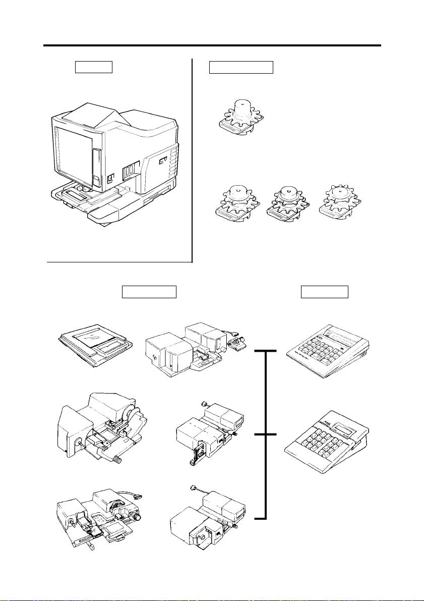
System Overview
2
FC-5
MS2000
Projection Lens
Single Lens
7.5
×
Zoom Lens
9-16
×
Film Carrier Controller
RFC-21
13-27
×
MARS C-4
23-50
×
RFC-9B
UC-2
RFC-15A
MARS MINI 2
RFC-15M
Page 6
3
Installation
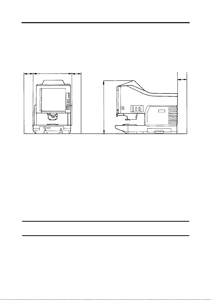
Space Requirements
There sh ould be a clearance of the foll ow ing dimens ions between the wal l and the rear of the
unit as well as on it's right and left sides to provide ample space for the ventilation ports to
dissipate heat.
100 mm
or 4"
503 mm or 19-3/4"
100 mm
or 4"
716 mm or 28-1/4"
100 mm
or 4"
Install a tion Site
For safe ty and to prevent possib le malfunctio ns of the unit, ins tall it in a location which
meets the following requirements.
A place away from curtains or other things that are easily flammab le.
u
An area that is safe from spilled water or other liquids.
u
An area fre e from direct sunlight.
u
A place out of the direct air str eam of an air conditione r, heater, or ventila tor.
u
A well ventilated place.
u
A dry place.
u
A dust-free location.
u
An area not subject to undue vibration.
u
On a stable and level surface.
u
NOTE
If the mach ine is placed near a window, make sure that the Screen faces away from it.
Page 7

Installation
Power Source
The power source volta ge requirements are as follows.
Use a power source with little voltage fluctuation.
u
Voltag e F lu ct ua ti o n: Within ±10 %
Frequen cy Fluctuati on: 50Hz Within ±2.5%
60Hz Within ±3%
Be carefu l not to exce ed the capacity of the outlet, especially when sourcing other
u
applia nces from the same outlet.
The outle t should be located near the unit and be easily accessib le so that the power cord
u
can be unplugged immedia tely if neces sary.
NEVER conn ect any other appli ances or un its by means of a multiple socket to the outlet
u
being used for the unit.
If an extension cord is needed, use one with a capacity greater than the power
u
consumption of the unit.
Make sure that the power cord and extension cord do not become caught underneath the
u
weig ht of th e unit.
4
Page 8

5
Parts Identifi cation
Screen :
Indication Panel:
Image Rotation Knob:
Projection Lens
(optional):
Fiche C a rr ier 5
(optional):
Projection Unit:
Connectors:
Power C o rd S o cket:
Power Switch:
Interface Connector:
The image taken from the film is projected here for viewing. The frame on the Screen marks the data reading
range.
Shows the status of the unit.
Used to turn the Prism Unit (optional) built into the
machine, thus turning the image on t he Screen.
Used to vary the size and adjust the focus of the image on
the Screen.
Suppo rt s th e viewing o f sh ee t film.
Contains are Mirror and Lens which projects the film
image onto the Screen.
Provides connection points for the various options (Roll
Film Carri er and Controll er).
Plug the power cord furnished with the unit into this
socket.
Use to turn the unit ON or OFF.
Connects the unit to a host computer through an Interface
cable.
Page 9

Explanation of the Indicator Panel
6
Status Window:
Status Displ ay
1 (lit) Ready to read data
1 (blink ing) Warming up OR reading data
The Projection Lamp has burnt out. The L2
L2
C1 Light so u rc e ma lf un c tio n
C2 Scanning malfunct ion
C4 Fan malfunction
code is also displayed whenever the light
source is blocked and the screen goes to black
while re ading data .
Service Indicator:
Displays the following operating conditions of the
machine.
Reason
This indicator (red) lights up when a malfunction occurs.
The nature of the problem is displayed in the Status Window.
NOTE
Should the Call Technical Representative Indicator be
displayed, immediately turn OFF the Power Switch and
unplug the power cord from the power outlet.
Call your Technical Representative and inform him/her
of the operating and running conditions of the unit.
Service
Indicator
Off
On
Scan Counter Key:
By pressing the tip of a pen-like instrument on this key,
the tota l scan q uantity of th e un it is enter ed an d d is played
3 times, 2 numerals at a time.
For example, if you entered 123, 456 times the display
would appea r as:
(normal display)
Page 10

7
Turning the Machine ON and OFF
Turning ON
Depress the Power Switch to the ON
1
position.
The Status Win dow displays a
2
blinking "1" a nd t he mach ine star ts to
warm up.
Turning OFF
Depress the Power Switch to the OFF position.
NOTE
Printing is not possible while the display
in the Sta tus Window is blinking.
The display wil l chang e once the machi ne
has finished warming up.
Page 11

Selecting a Proje cti on Lens
The Proje ction Lens com es in the following four types.
Select one that corresponds to the film being us ed.
The list of standard types of microfi lm and the recommended magnification rat io of lenses to
be used on the machine is gi ven below.
7.5
×
9-16
×
13-27
23-50
Film Format Frames 7.5
35 mm
(TYPE 1: Blue)
(TYPE 1: Blue)
(TYPE 2: Green)
×
(TYPE 3: Yellow)
×
: Recommended Projection Lens
Projection Lens
××××
Half — — —
Full — —
9-16
××××
13-27
××××
23-50
××××
8
16 mm
Source
Document
COM
Half — — —
Full — —
60 — — —
98 — —
325 — — —
420 — — —
63 — —
70 — — —
80 — —
84 — —
120 — —
208 — — —
270 — — —
Page 12

9
Replacing the Proj ect io n Lens
To insta ll a Le ns wi th a m agnif icatio n diff erent from t hat al read y inst alled in the machin e,
follow the procedure gi ven below.
Take hold of the Prism Holder Lever
1
and pull it u p to raise th e Prism
Holder.
Pull out the Lens Unit.
2
Pull out the Brightness Select Le v er
4
and slide it to a positi on appropriate
for the ty pe of the Projection Lens
loaded in th e m a ch in e.
The lever should click into position.
NOTE
Brightness on the Screen is uneven it t h e
Brightness Select Lever is not placed in a
position corresponding to the type of the
Projection Lens being used. Be sure to
place the Lever into the correct position
according to the type of Projection Lens.
TYPE 1
TYPE 2
TYPE 3
Slide the Lens Unit into the machine
3
along the Lens G uide.
Page 13

Zooming and Fo c us in g
10
Zooming of the Screen Image
Rotate the Zooming Ring Dial to
1
bring th e im ag e on the Scree n int o
print size frame.
Marked on the Screen are the size
2
frame markers corresponding to the
paper size (A4 or 8-1/2"× 11").
Zoom the film image so that it fits
inside the marker s.
A4 or
8-1/2" × 11"
Lengthwise
Focusing of the Screen Image
Rotate the F ocusi ng Ri ng Di al to b ring th e
image on the Screen into f ocus.
A4 or
8-1/2" × 11"
Crosswise
Page 14

11
Image Rotation
To turn the image on the Screen, turn the Image Rotation Knob.
The machine must be equipped with a prism (option) to effect i mage rotation.
If an optional Auto Image Rotation Unit (Option) is installed, the image can be turned electrically.
Manual Rotation (standard): operate by hand
Turn the Image Rotation Knob beside the Lens Holder to turn the image mechanically as
require d.
Auto Image Rotation (option): Motor-driven
Turn the Image Rotatio n K nob on the bottom right of the Screen Frame to turn the image.
The greater the tur ning angle of the Image Rotation Knob, the faster the turning speed.
Page 15

12
Replacing the Proj ect io n Lam p
If the le vel of brightness on the Screen is drast ically reduced or when the Projecti on Lam p is
burned out , replace the Lamp with a ne w one by following the procedure given below.
Use the following procedure to replace the Projection Lamp whenever a reduction of brightness on the screen is detected.
Once the system detects that the Projec tion Lamp has burnt out(L2 is displayed), th e scan job
will be cancelled. If the system is operating in the auto-scan mode, the scanning operation
will st op.
Make sure that the replacement lamp is specified for use with this scanner. (DC20V 150W
DDL type)
CAUTION
Do not touch with bare hand and extremely hot Projection Lamp immediately after the
machine has been turned OFF.
Place the Power Switch in the OFF
1
positio n and slide the Projection Unit
out of the machine.
Remove the Projection Lamp from
2
the Lamp Hol der.
Remove the Projection Lamp from
3
the Lamp Socket.
Inser t a ne w Projection Lamp so that
4
the mark on it s base is facing
upwards. Make sure th at the new
Projection Lamp is inserted securely
so that there is no gap between the
Projection Lamp and the Lam p
Socket.
NOTE
Do not touch the reflector mirror surface
of the Projection Lamp. Fingerprints,
smudges or debris should be wiped clean
with a soft, dry cloth.
Mark
Page 16

13
Replaci n g the Projection Lamp
Insert the new Projecti on Lam p all
5
the way into the Lamp Hol der.
Slide the Projection Unit back into
6
the machine.
NOTE
If the Projection Unit is not properly
installed, power will not be supplie d and
the machine will not operate.
Turn th e P ow e r S w itc h ON .
7
Page 17

14
Daily Mainte nance
To ensure accurate reading and optimum scanning quality, the unit should be cleaned on a
daily basis.
Cleaning the Screen
With a damp cloth, clean and remove any
dust or debris from the Screen. Dry the
Screen with a soft, dry cloth.
NOTE
NEVER use alcohol or any other solvent
when clean ing to avoid caus ing damage
to the Scr een or erasing of the markings.
Cleaning the Exterior Panels
Dust the exterior panels with a soft cloth.
Cleaning the Optional Carrier
Glass (Fiche Carrier 5)
With a da m p cloth, clean and remove
1
any dust or debris from the plates of
the Carrier Glass. Dry the Carrier
Glass plates with a soft, dry cl oth.
NOTE
The Projection Lens should be removed
BEFORE cleaning the Carrier Glass
plates.
Grasp the Handle of the Carrier and
2
pull it ou t gently as far as it will go.
The upper gl ass plate of the Carrier
will swing up.
Using the pr ocedure des cribe d above,
use a damp clot h to clean the inner
surfaces of the Carrier Glass plates.
Then dry the plates with a sof t, dry
cloth.
Page 18

15
Specification
Type
: Desk Top Type Microfilm Scanner
Film
: Microfiche, Aperture Card, Jacket, Roll Films (16 mm, 35 mm), both
Positive and Negative.
Magnification
Screen Siz e
Scanning Met hod
Scanning Size
Scanning Speed
Resolution
Auto Function
Light Source
Power Consumpt ion
Power Requirement
Dimensions
Weight
Standard Accessories
Option
: Single Lens ... ..7.5
Zoom Len s. ... ..9×-16×, 13×-27×, 23×-50
: 300 mm × 300 mm or 12" × 12"
: Scanning/Scanning directi o n : CCD scannin g
Scanning/Feeding direction : Mirror scanning
: 300 mm × 300 mm or 12" × 12"
: 6.5 sec. /1 frame scanning (8-1/2 " × 11" or A 4 V erti ca l/400 dp i/ AE
Mode)
: 200, 300, 400 dpi
: Determines of N ega or Posi, Masking, Center ing, Full Frame
Skew Correction (Operation from the host computer.)
: Halogen Lamp (DC20V 150W DDL Type)
: Less than 300W (Less than 350W: with option)
: 120VAC (60 H z), 220/230-240VAC (50- 60H z)
110VAC (60Hz), 127VAC (60Hz)
: 503 mm (W) × 821 mm (D) × 716 mm (H) or
19-3/4" (W) × 32-1/3" (D) × 28-1/4" (H)
: 39 kg. or 86 lbs.
: Power Cord, Operator's M anual (this manual), SCSI Cable
: Single Lens, Zoom Lens, Prism Unit, Fiche Carrier 5, Roll Film
Carrier 9B, Roll Film Carr ier 15A, Roll Film Carrier 15M, Roll
Film Carrier 21, Universal Carrier UC-2, Mars Controller 4, Mars
Mini Controller 2, Auto Image Rotation Unit, Counter Kit
×
×
Page 19

16
Troubleshooting
Review the following chart whenever you experience operational problems. If performance
does not improve even after following these procedures, contact your Technical Representative.
Problem
The display stays
blank after you have
turned on the
machine.
The ma ch ine does
not scan.
(L2 is displayed).
Cause Action
The power cord is not connected
correctly.
The Projection Unit has not been
installed properly.
The Projection Lamp is burned
out.
The carrier glass is covered by a
dark colored piece of paper or
some other thing that would prevent light from shining through
the glass.
Make sure that the power cord
is connected correctly.
Install or reinstall the Projection Unit (see page 12).
Replace the Projection
Lamp.(F or detailed information, see page 12.)
Remove paper or any other
obstruction from the carrier
glass, turn the power switch
OFF and then ON again to reset
the syste m.
Page 20

17
For Key Operator's Use
When you need to call for service, the Key Operator should be prepared to provide the following information to your local authorized Deal er.
1. Your Company Name, Address, Telephone Number, Department Name, Floor Number,
Machine Location, et c.
2. Model Name, Serial Number, Condition or System(s) Indication(s) on the Di splay, etc.
For your reference purpose.
Model Name MS2000
Attached Accessories
Installa tion Data
Authorized Dealer's Name
TEL. No.
Address
Serial No.
Serial No.
Serial No.
Serial No.
Serial No.
Serial No.
Serial No.
Serial No.
Page 21

Memo
Page 22

Memo
Page 23

1998. 7
Copyright
1998 MINOLTA CO., LTD
Printed in Japan
The information contained in this manual is
subject to change without notice to
incorporate improvements made on the
product or products the manual covers.
MINOLTA CO., LTD.
Image Information Products Marketing Headquarters
3-13, 2-chome, Azuchi-machi, Chuo-ku, Osaka. 541-8556, Japan
 Loading...