

Page 1

Software License Agreement and Warranty
(i) Fo r the U.S. and Canada
Software License Agreement
Importan t:
Before installing the software please careful ly read thi s License Agree men t. The
installation of this software indicates your acceptance of the terms and conditions of
this License. If you do not agree with the terms and conditions, you should return the
software to Minolta Corporation for a full refund.
Ownership:
The software is owned and copyrighted by Minolta Corporation and its third party
suppliers. Your license confers no title or ownership in the Software and should not be
construed as a sale of any right in the Software. Minolta’s third party suppliers may
protect their rights in the event of any violation of these terms.
The License permits you to:
1. Use this software in the conduct of business without limit when the software is
used with the intended Minolta Product.
2. SOFTWARE: You may install and use the SOFTWARE on a computer to which
the Minolta Printer is attached.
OR
NETWORK: If the software is installed on a computer acting as a network
server, any number of computers or workstations may access or utilize the printer
services of that server. The printer services are described in the printed materials
accompanying the Printer Network Card.
The following uses are not permitted:
1. Making of alterations to the software
2. Right to grant sub-license, leases or other rights to others.
3. Merge this software product or any portion of it into another product or program
4. You may not reverse engineer, decompile, or disassemble the software
Export Requirements:
You may not export or re-export the software or any copy or adaptation in violation of
any applicable laws or regulations.
1
Page 2

Software License Agreement and Warranty
Notes:
By installing this software, you acknowledge that you have read this agreement,
understand it and agree to be bound by its terms and conditions. You further agree that
this is the complete and exclusive statement of the agreement between us and
supersedes any proposal or prior agreement either oral or written, and any other
communication between us r elating to the subject ma tter of thi s agr eement. You f urther
agree that if Minolta Corporation is required to engage in any proceeding, legal or
otherwise to enforce its rights under this agreement, Minolta Corporation shall be
entitled to recover from Licensee, in addition to any other sums due, reasonable
Attorney fees, cost and disbursements.
Limited Software War r anty
Limited Warranty:
Minolta warrants that the software will perform in accordance with the accompanying
written materials for a period of (90) ninety days from the date of purchase. Minolta
does not warrant that the operation of the program will meet your requirements. This
limited warranty gives you specific legal rights. You may have others, which vary from
state/jurisdiction to state/jurisdiction.
Purchasers Remedies:
Minolta’s entire liability and your exclusive remedy with respect to the software shall
be at Minolta’s option either, repair or replacement of the software. The software must
be returned to Minolta with a copy of your proof of purchase. The Limited Warranty is
void if failure of the software has resulted from accident, abuse, or misapplication. Any
replacement software will be warranted for the remainder of the original warranty
period or (30) thirty days, whichever is longer.
The remedies provided herein are customer’s sole and exclusive remedies. In no event
shall Minolta Corporation be liable for any lost profits, direct, indirect, special,
incidental, or consequential damages, whether based on contract, tort, or any other
legal theory.
2
Page 3

Software License Agreement and Warranty
Minolta Network Card W arranty
Warranty Term:
Minolta Network Cards have a (1) One Year Warranty. The Network Card must be
returned to Minolta for repair or replacement at Minolta’s discretion.
Warranty Coverage:
Minolta Corporation warrants this product to be free from defects in workmanship and
materials for a period of one year from the date of receipt of the unit. If the unit fails to
function as written in the User Manual, Minolta will repair or replace the unit at no
charge. Minolta will ship at their expense a exchange unit overnight to replace the
defective unit.
The remedies provided herein are the customers sole and exclusive remedies. In no
event shall Minolta Corporation be liable for any lost profits, direct or indir ect, special,
incidental, or consequential damages, whether based on contract, tort, or other legal
history.
3
Page 4

Software License Agreement and Warranty
(ii) For Europe and other countries
PLEASE READ CAREFULL Y TH E LICENSE AGRE EMENT BELOW BEFO RE
OPENING THIS PACKAGED SOFTWARE. OPENING THIS PACKAGE
INDICATES YOUR ACCEPTANCE OF THE TERMS AND CONDITION BELOW.
IF YOU DO NOT AGREE WITH THEM, YOU SHOULD PROMPTLY RETURN
THE PACKAGE UNUSED.
1.SOFTWARE
Software means the computer program contained in this package (which may include
digitally encoded, machine readable, scalable outline font data as encoded in a special
format), together with all codes, techniques, software tools, format, design, concepts,
methods and ideas associated with the computer program and all documentation related
thereto.
2. LICENSE AGREEMENT
This is a license agreement and not an agreement for sale. Minolta owns, or has been
licensed from other owners, copyrights in the Software. Except as stated in this
Agreement, you are not granted any rights to patents, copyrights, trade names,
trademarks (whether registered or unregistered), or any other rights, franchises or
licenses in respect of the Software. Title to the Software and any copy made from it is
retained by Minolta or such other owners.
3. LICENSE
Minolta, hereby grant to you, and you agree to accept a non-exclusive, non-transferable
and limited license and you may:
(1) install and use the Software on a single computer and one associated printer.
(2) use the Software only for your own customary business or personal purpose.
(3) make a copy of the Software for backup or installation purpose only in support of
the normal and intended use of the Software.
(4) transfer possession of copies of the Software to another party by transferring a
copy of this Agreement and all other documentation along with at least one
complete unaltered copy of the Software, provided that (i) you must, at the same
time, either transfer to such other party or destroy all your other copies of the
Software. (ii) such transfer of possession terminates your license from Minolta,
and (iii) such other party shall accept and be bound by these license terms by its
initial use of the Software.
4
Page 5

Software License Agreement and Warranty
4. RESTRICT IONS
(1) You shall not without the written consent of Minolta:
(i) use, copy , modify, merge or transfer copies of the Software except as provided
herein.
(ii) reverse assemble or reverse compile the Software except as permitted by law;
or
(iii) Sublicense, rent, lease or distribute the Software or any copy thereof.
(2) You shall not export or re-export the Software in any form under violation of
export restrictions by the government of your country.
5. LIMITED WARRANTY
Minolta warrants the media on which the Software is recorded to be free from defects
in materials and workmanship under normal use. Warranty details and limitations for
the Software are described in the Statement of Limited Warranty which was supplied
with the hardware. With the exception of the foregoing express warranties applicable to
hardware and media only, the Software is not warranted and is provided
SUCH WARRANTIES ARE IN LIEU OF ALL OTHER WARR ANTIES, EXPRESS
OR IMPLIED, INCLUDING, BUT NOT LIMITED TO, THE IMPLIED
WARRANTIES OF MERCHANTABILITY AND FITNESS FOR A PARTICULAR
PURPOSE.
6. LIMITATION OF REMEDIES
IN NO EVENT WILL MINOLTA BE LIABLE FOR ANY LOST PROFITS, LOST
DATA, OR ANY OTHER INCIDENTAL OR CONSEQUENTIAL DAMAGES
THAT RESULT FROM USE OR INABILITY TO USE THE SOFTWARE, EVEN IF
MINOLTA OR ITS AUTHORIZED REMARKETERS HAVE BEEN ADVISED OF
THE POSSIBILITY OF SUCH DAMAGES OR FOR ANY CLAIM BY YOU
BASED ON A THIRD PARTY CLAIM.
7. TERMINATION
You may terminate your license at any time by destroying the Software and all your
copies of it or as otherwise described in these terms. Minolta may terminate your
license if you fail to comply with these terms. Upon such termination, you agree to
destroy all your copies of the Software.
8. GOVERNING LAW
This Agreement shall be governed by the laws of the country where the delivery is
made to the original customer.
5
Page 6

Software License Agreement and Warranty
9. GOVERNMENT END USERS
If you are acquiring the Software on behalf of any unit or agency of the United States
Government, the following provisions apply. Use, duplication or disclosure by the
Government is subject to restrictions as set forth in the Rights in Technical Data and
Computer Software clause at FAR 252.227-7013, subdivision (b)(3)(ii) or
subparagraph (c)(1)(ii), as appropriate. Further use, duplication or disclosure is subject
to restrictions applicable to restricted rights software as set forth in FAR 52.22719 (c)
(2).
YOU ACKNOWLEDGE THAT YOU HAVE READ THIS AGREEMENT,
UNDERSTAND IT, AND AGREE TO BE BOUND BY ITS TERMS AND
CONDITIONS. NEITHER PARTY SHALL BE BOUND BY ANY STATEMENT
OR REPRESENTATION NOT CONTAINED IN THIS AGREEMENT. NO
CHANGE IN THIS AGREEMENT IS EFFECTIVE UNLESS WRITTEN AND
SIGNED BY PROPERLY AUTHORIZED REPRESENTATIVES OF EACH
PARTY. BY OPENING THE PACKAGE, YOU AGREE TO ACCEPT THE TERMS
OF THIS AGREEMENT.
6
Page 7

Table of Contents
Organization
This manual has been divided into six sections. Section I contains hardware
descriptions and installations. Section II contains information on enhanced print server
management. The Network Operating System (NOS) protocol sections are found in
Sections III through VI.
All sections in this manual have been designed to be independent of another.
Chapter 1 Hard ware Installation
Hardware installation......................................................................1-2
Hardware Trouble shooting............................................................1-7
Sample Configuration Sheet...........................................................1-8
Mechanical Specifications............................................................1-10
Wiring Specifications...................................................................1-11
Chapter 2 Enhanced Management Features
SNMP.............................................................................................2-2
Checking Printer Status..................................................................2-4
Chapter 3 NetWare
Introduction ....................................................................................3-3
Minolta Network Utility for NetWare............................................3-5
Additional Utility Options.................................................. ..........3-14
Minolt a N e t w o rk for NDS.......... ........ ................. ........ ........ ........ .3-20
Chapter 4 TCP/IP
Introduction ....................................................................................4-4
Configuring the Minolta Network device.......................................4-6
TCP/IP Configuration and Printing..............................................4-12
Minolta Network Utility for TCP/IP ............................................4-19
Additional utility Options....................................... .......... .......... ..4-27
Telnet Configuration....................................................................4-35
Troubleshooting............................................................................4-41
Application Considerations ..........................................................4-47
i
Page 8

Table of Contents
Chapter 5 Apple EtherTalk
Introduction ....................................................................................5-2
The Minolta Network Utility..........................................................5-3
Troubleshooting..............................................................................5-9
Selecting Your Printer.................................................................5-13
Capturing With a Spooler.............................................................5-14
Software License Agreement and Warranty
(i) For the U.S. and Canada
(ii) For Europe and other countr ies
ii
Page 9

Overview
Network Operating Systems
Minolta Network products simultaneously support several network
protocols in various combinations. Below is a list of supported
network protocols accompanied with NOS/OS requirements.
Novell NetWare
Novell NetWare versions 3.x, 4.1 and higher.
TCP/IP and Windows NT
TCP/IP, FTP and Remote LPD protocols. Simple Network
Management Protocol (SNMP) and Windows NT are supported in
this environment.
Apple Ether Talk
Macintosh System 6.x or later and LaserWriter Driver version 8.x.v
iii
Page 10

Technical Support
To Contact:
Minolta Corporation
Addr: 101 Williams Drive, Ramsy, New Jersey 07446
Czechia : Minolta spol,s.r.o,Vever 102,65910,BRNO
Austria : Minolta Austria GmbH,Amalienstrasse 59-61,1131 Wien
Belgium : Minolta Business Equipment S.A.,IndustrieparkKeiberg,
Excelsiorlaan 10, 1930
Denmark : Minolta Danmark a/s,Valhojs Allee 160,2610 Rodovre
Finland : Oy Facit Electronics Ab, P.O. Box 93,02201 Espoo
France : Minolta France Sa.,Div.Equipement de Bureau,
365-367 oute de Saint Germain,78424 Carrieres Sur
Seine Cedex
Germany : Minolta Germany,Minoltaring 11,30855 Langenhagen
Italy : Minolta Italia,Via Stephenson 37,20157 Milano
Netherland : Kopieersystemen Netherland B.V.,Schipholweg 343,
1171 PL Badhoevedorp
Portugal : Minolta Portugal Lda., Av. do Brasil 33a, 1700 Lisboa
Spain : Minolta Business Equipment Spain S.A.,Paseo de la
Castellana 254,28046 Madrid
Sweden : Minolta Business Equipment Ab,Albygatan
114,17109 Solna
United Kingdom :Minolta U.K. BEO,Rooksley Park,Precedent Drive/
Rooksley, Milton Keynes MK 13 8Hf
Bulgaria : Minolta Bulgaria o.o.d., Ulica Christo Georgiev
4,1504 Sofia
Budapest : Minolta Magyarorszag KFT,Galvani u. 4, 1117
Budapest
Tel: 1-888-2-MINOLTA (1-888-264-6658)
Tel:05-7269511 Fax:05-7269545
Tel:01-87882-0 Fax:01-87882-271
Tel:02-720967-0 Fax:02-720097-1
Tel:36370333 Fax:36370200
Tel:90-4206-1 Fax:90-4206-200
Tel:1-3086-6272 Fax:1-3086-6297
Tel:0511-7404-450 Fax:0511-7404-627
Tel:02-39011-1 Fax:02-39011-219
Tel:020-6584-141 Fax:020- 6597436
Tel:01-79300-16 Fax:01-7969547
Tel:91-7337811 Fax:91-7332262
Tel:08-6277-500 Fax:08-6277-607
Tel:0345-211-211 Fax:01908-200-379
Tel:0466-052 Fax:0467-066
Tel:0181-07-20 Fax:0161-04-79
iv
Page 11

Technical Support
Poland : Minolta Polska sp.zo.o.,Ul,Nowolipie 7A, 00-146
Warszawa
Tel:0311-488 Fax:0635-37-56
Romania : Minolta Romania SRL,Soseaua Oltenitei 35-37,etaj
8,Sector 4,71212 Bucuresti
Tel:0634-62-45 Fax:0330-70-02
Slovakia : Minolta Slovakia Spol.s.r.o.,Prievozsk 18,821 09
Bratislava
Tel:052-13-338 Fax:052-15-258
Slovenia : Minolta Slovenia d.o.o.,Ptrujska 19,61000 Ljubljana
Tel:0168-11-05 Fax:0168-10-28
Baltia : Minolta Baltia,Didzioji 11,2001 Vilnius/Litauen
Tel:0222-029 Fax:0223-060
Ukraina : Minolta Ukraina,Bulvar Lesi Ukrainki 26,252 133
Kiev 133/ Ukraine
Tel:0296-65-66 Fax:0295-00-70
Czechia : Minolta Czechia spol.sr.o.,Veveri 102,659-10 BRNO
Tel:072-69-511 Fax:041-212-681
Czechia : Minolta Czechia spol.sr.o.,Vysehradsk§ 51,128 00
Praha 2
Tel:0297-879 Fax:0299-267
Zagreb : Minolta Zagreb d.o.o.Supilova 7,41000 Zagreb
Tel:0611-6655 Fax:0611-6656
Beograd : Minolta d.o.o.Beograd,Bitoljska 16,Beograd(Zarkoro)
Tel:0505-911 Fax:0505-911
v
Page 12

Technical Support
When you call Techinical Support, the following information will help us answer your
questions more quickly and accurately. Please be able to identify the following:
• Minolta Network device serial number
• Minolta Network device configuration sheet
• Type of network cable connected to the Minolta Network device
• Computer and network adapter card make and model numbers
• Nerwork Operating System and version number
Please write these numbers down in the space provided below for future reference.
Minolta Network device S/N:
Ethement ADDR: :::::
vi
Page 13

Chapter 1
Hardware Insta lla tio n
Chapter 1
Hardware Installation
Page 14

Page 15

In This Chapter
Hardware Installation ......................................................................1-2
Product Overview....................... .......... ................... .......... .......... ...1-2
Hardware Description.....................................................................1-3
Installing the Minolta Network device...........................................1-5
Powering on the Equipment ...........................................................1-6
Printing a Configuration Sheet from the Control Panel.................1-6
Hardware Troubleshooting..............................................................1-7
Minolt a N e t w o rk Print Serv er Status ..... ......... ........ ........ ........ .......1-7
Unable to Print................................................................................1-7
Hardware Error Messages ..............................................................1-7
Sample Configuration Sheet...........................................................1-8
Chapter 1
Mechanical Specifications ............................................................1-10
Wiring Specifications.....................................................................1-11
Connector Specifications..............................................................1-11
Hardware Installation
1-1
Page 16

Hardware Installation
Product Overview
The Minolta Network device is a multi-protocol network interface
card. The Minolta Network hardware installs in the controller of the
printer and allows Ethernet network users to connect directly to the
printer.
The Minolta Network package contains the following:
• Minolta Network User's Guide (this manual)
• Minolta Network print server
• 4 (3.5") diskettes labeled
Hardware Installation Chapter 1
• Product registration card
Flexible Ethernet Connection
The Minolta Network device is equipped with two connectors: thin
Ethernet (10BASE2), twisted-pair (10BASE-T). Only one of the two
connectors can be active at a time.
Minolta Network Utilities for NetWare
Minolta Network Utility for TCP/IP
Minolta Network Utility for EtherTalk
1-2
Page 17
Hardware Description
The Minolta Network device assembly fits into the controller.
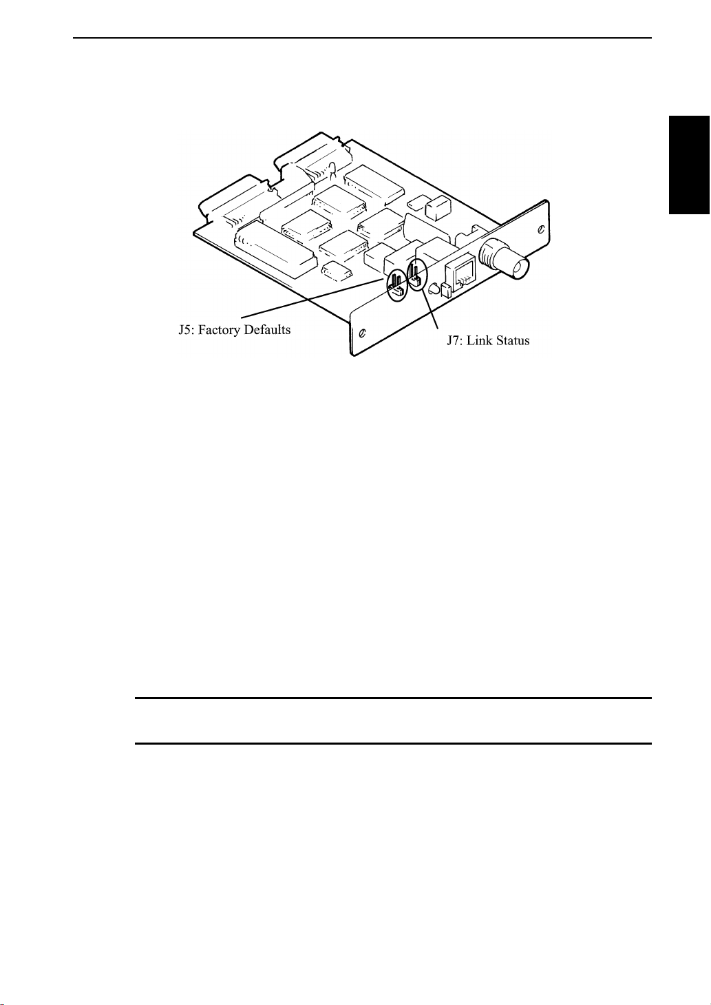
Jumper Switches
• Restore Factory Defaults (J5):
When this jumper is loaded and the print server is installed in the
printer and power is turned on, all variables are reinitialized to their
factory settings. The status LED (round orange/green) will flash
orange and eventually turn solid green when the factory settings have
been reset. The jumper must be removed prior to re-configuring the
print server and resuming standard operation.
Hardware Installation
Chapter 1
Hardware Installation
• Link Status (J7):
This jumper is provided to allow the Minolta Network device to
support a 10BASE-T connection to some older hubs that do not
provide a Link Status signal. Loading this Jum per forces L ink Status.
The 10BASE2 connection may not function correctly if the Link
Status jumper is loaded.
CAUTION: Do NOT change the default jumper setting without instructions
from our Technical Support.
Link Status Indicator
If the 10BASE2 connector is used or the cable is disconnected, the
link status indicator (the rectangular, green indicator) will remain of f .
The indicator will illuminate green when a connection has been
established with a 10BASE-T hub or when the Link Status Jumper
(J7) is installed.
1-3
Page 18

Hardware Installation
Hardware Installation Chapter 1
Status Indicator
When the printer is powered-on, the Minolta Network device
executes a self-test diagnostic. The indicator flashes red during selftest and changes to solid green when the Minolta Network device
passes self-test. The Status indicator flashes green whenever the
Minolta Network device is receiving data or is sending data to the
printer. The Status indicator will remain red if the Minolta Network
device fails self-test or if communication with the printer is
unsuccessful. If your Minolta Network device fails self-test, consult
Hardware T roubleshooting.
10BASE2 COAX, Thin Ethernet Cable
Thin-wire (coaxial) Ethernet cabling must be terminated with a 50ohm terminator at both ends of the line. Y ou will need to use an
Ethernet T-connector to install the Minolta Network device. Unless
you are using special centralized cabling, network operation will be
interrupted while you add the Minolta Network device on a thin-wire
network. The Minolta Network device auto-senses a 10BASE2
connection.
10BASE-T UTP, Unshielded Twisted-Pair Cable
Twisted-pair systems utilize 10BASE-T hubs or concentrators.
Adding the Minolta Network device will not interrupt network
operation. The Minolta Network device auto-senses a 10BASE-T
connection.
1-4
Page 19

Installing the Minolta Ne twork device
Minolta Network device installation consists of the following:
• Turn the printer off
• Ground yourself
• Install the Minolta Network device
• Connect the network cabling
• Power on the printer
• Run the appropriate network utility
NOTE: If you have not already done so, we recommend that you write down
the serial number and Ethernet address of your Minolta Network device for
future reference. We have provided a space on page 6 for you to record these
numbers.
Installation Steps
1. Turn the printer off, unplug the power cord, and disconnect all
cables.
Hardware Installation
Chapter 1
Hardware Installation
2. Ground yourself by touching the metal frame of the printer and
then remove the Minolta Network device from its protective
bag.
CAUTION: The Minolta Network device is sensitive to static electricity.
Please observe the following precautions when handling the Minolta Network
device:
• Leave the card in the anti-static bag until you are ready to install.
• Grasp the edges of the board only.
• Do not bring the card into contact with carpet, fabrics or ungrounded
surfaces.
• Return the card to the anti-static bag if you remove it from the
printer.
3. Push the Minolta Network device into the controller until the
two holes in the bracket line up with the screw holes in the back
of the printer. Install the two screws.
4. Connect the network cabling. (See the previous page for cabling
information.)
1-5
Page 20

Hardware Installation
Powering on the Equipment
Apply power to the printer. The status indicator will flash orange
during self-test. The indicator changes to green when the card passes
self-test.
Printing a Configuration She et from the Control Panel
If requested, the Minolta Network device generates a configuration
sheet via the printer control panel. A configuration sheet provides
configuration and status information, as well as network statistics.
Once the Minolta Network device is operating, you can also print a
configuration sheet at any time using the Minolta Network utilities.
Hardware Installation Chapter 1
Refer to the printer manual for documentation on using the printer
menu to print a configuration sheet.
1-6
Page 21

Hardware Troubleshooting
Minolta Network Print Server Status
Upon power-up, the LED flashes orange. It changes to green when
the Minolta Network device passes self-test. The LED stays orange if
the Minolta Network device fails self-test or if communication with
the printer is unsuccessful. If the LED turns solid orange due to a
network protocol error, a configuration sheet will be printed
automatically. Check the error message reported on the configuration
sheet.
Unable to Print
If your Minolta Network device passes self-test and you are unable to
print a configuration sheet or are unable to send data to the printer via
the Minolta Network device, check the following:
• Printer configuration
• Printer hardware
• Computer network adapter cards
• Cabling and/or connectors
• Application software configuration
Chapter 1
Hardware Installation
Hardwa re Error Messages
If you receive the following message:
ST: Cable not connected
self-test has determined the network cable is not connected. Check
the cable connection to the Minolta Network device.
If you find the cable is connected and you are still receiving this
message or any other “ST:” error message, power the printer off and
on. If the error continues, connect the Minolta Network device to a
network connection that is functioning correctly. If the error still
continues, call T echnical Support.
1-7
Page 22

Sample Configuration Sheet
Minolta Network Conf iguration Sheet 1 of 2
NJ, USA/ Germany
General
Serial Number: 1716461
Ethernet Address: 00.40.68.1A.30.ED Cable Type: 10BASE-T
F/W Version: 5.04a(9634A) Polarity: Normal
Rx Packets: 173 Tx Packets: 165
Rx Packets Unavailable: 0 Tx Packet Errors: 0
Rx Packet Errors: 0 Tx Packet Retries: 0
Checksu m Errors: 0
Error: None
Hardware Installation Chapter 1
NetWar e (ENABLED)
Mode: PSERVER
Minolta
Link Status: Good
File Server Name (s ):
NIC3 Up
Print Server Name: MLT 1716461
Bindery File S e rve r: NIC3
Queue Scan Time: 4.0 seconds
Frame Format: Ethernet 802.2
JetAdmin: Disabled
Trap Destination: 00.00.00.00: 00.00.00.00.00.00
TCP/IP (ENABLED)
IP Address: 198.102.102.254
Subnet Mask: 255.255.255.0
Default Gateway Address: 0.0.0.0
Time-out Checking: Disabled
Trap Destination: 255.255.255.255
1-8
Page 23

Minolta Network Conf iguration Sheet 2 of 2
EtherTalk (ENABLED)
Node Address: 003281h
Router Address: 0032E9h
Status: Running
Port 1 Enabled
Printer Name: “MLT 176461”
Printer Type 1: “LaserWriter”
Zone Name: “lab1”
LAN Server (ENABLED)
Sample Configuration Sheet
Chapter 1
Port Configuration
Name:
Printer Status: Online
Connected To: printer
Error: None
Hardware Installation
1-9
Page 24

Mechanical Specifications
Physical Di mensions
Net Weight
Power Dissipation
Relative Humidity
Hardware Installation Chapter 1
Length
Width
Height
Operating
Temperature Operating
Non-operating
Operating
143mm
125mm
24mm
0.1252kg (0.276lbs.)
2.75watts (550ma@ +5 VDC)
10-32°C
10-35°C
5-90% non-condensing
1-10
Page 25
Connector Specifications
For your reference, we have included the following connector pin
assignments.
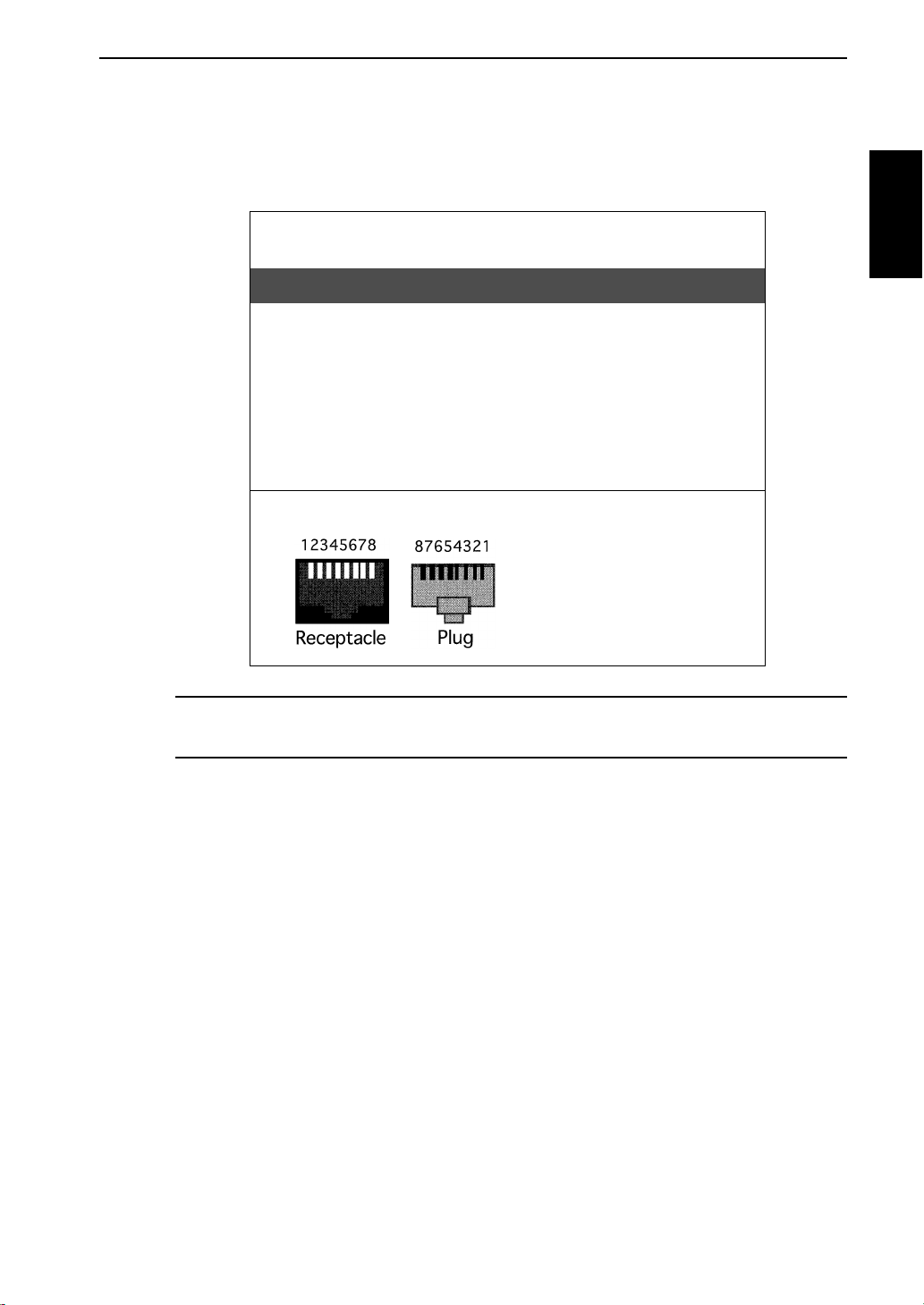
Minolta Network, ETHERNET, 10BASE-T
CONNECTOR SIGNAL ASSIGNMENTS
Pin # ................ Signal Name ...........Descriptions
1 ....................... TD+ .........................TRANSMIT DATA +
2 ....................... TD- ..........................TRANSMIT DATA -
3 ....................... RD+ .........................RECEIVE DATA +
4 ....................... N/C
5 ....................... N/C
6 ....................... RD-..........................RECEIVE DATA -
7 ....................... N/C
8 ....................... N/C
RJ45 Pin Identification
Wiring Specifications
Chapter 1
Hardware Installation
NOTE: For proper operation the 10BASE-T cable must have t wo twisted-wire
pairs
1-11
Page 26

Page 27

Chapter 2
Management Feature s
Management Features Chapter 2
Page 28

Page 29

In This Chapter
SNMP .................................................................................................2-2
Overview ........................................................................................2-2
Private MIB....................................................................................2-2
Traps...............................................................................................2-3
Security ...........................................................................................2-3
Checking Printer Status ...............................................................2-4
Minolt a N e t w o rk d e v i c e W eb St atus...... ......... ........ ................ .......2- 4
HP JetAdmin ..................................................................................2-4
Management Features Chapter 2
2-1
Page 30

SNMP
Overview
Simple Network Management Protocol (SNMP) provides network
administrators with the ability to communicate management
functions between an SNMP manager and an SNMP agent. An
SNMP manager is a user program that the network administrator can
use to manage SNMP agents. The manager can retrieve “GET”
information from the agent or alter “SET” information on the agent.
An agent can also send an unsolicited message (trap) to a manager
when it encounters an unusual condition.
The Minolta Network device is a fully functional SNMP agent and
supports any standard SNMP management platform, including:
•HP OpenView
• Novell NMS
• Sun SunNet Manager
• IBM NetView
Private MIB
Management Features Chapter 2
Minolta Network SNMP support has been enhanced with a private
MIB. It is accessible via SNMP over TCP/IP and IPX. This private
MIB contains over 150 configuration and status variables for the
network protocols, printer interface, network interface and the over
all Minolta Network device status. Printer status traps such as online,
offline and printer error are also provided.
The setting of certain variables causes an immediate firmware reset.
These variables are listed in the private MIB under cmdReset.
NOTE: If you attempt a reset while a job is printing, the job may not print successfully.
Certain variables are critical, that is, they change a fundamental
operating parameter of the Minolta Network device. These variables
are saved by the Minolta Network device, but are not actually used
until it is power cycled or reset. When any one of these variables are
changed, the variable genConfigDirty is automa tically set to “yes” by
the print server.
This signifies a reset is required for all configuration changes to be
made active. Minolta recommends checking the genConfigDirty
variable after using a MIB browser to make any configuration
2-2
Page 31

Traps
SNMP
changes to the Minolta Network device. If genConfigDirty is set to
“yes”, then the cmdReset variable should also be set to yes. This will
cause the Minolta Network device to reset, make all configuration
changes active on the Minolta Network device and set both the
cmdReset and genConfigDirty variables to “no”. These critical
variables are listed in the private MIB under “genConfigDirty”.
Trap s are unsolicited infor mation from the SNMP agent. The Mi nolta
Network device uses a ColdStart trap to inform the manager it has
been powered on or reset. An authentication failure trap is sent when
the Minolta Network device receives an SNMP trap “GET” or “SET”
request with an incorrect community name.
The Minolta Network device sends printer traps when there is a
change in the status of the printer . If the printer goes offline or runs
out of paper, the administrator will be notified via the Minolta
Network device traps over both UDP and IPX. Additionally, the
Minolta Network device can send traps on “toner low”, “paper jam”,
and “printer cover open”. The traps may be configured for specific
destination addresses.
Management Features Chapter 2
Security
In order to receive Extended Status traps, the Minolta Network device
must have bidirectional status enabled (it is disabled by default).
Extended Status can be enabled through the Minolta Network device
Configuration utility (telnet) from the Configure Data Channel
option. You can also enable Extended Status through the Minolta
Network Utility for TCP/IP from the Output file tab.
SNMP implements a simple security system known as community
names. Each SNMP message has a community name associated with
the command in the message. SNMP allows for a set community
name, get community name and a trap communityname. When the
SNMP Agent receives a command, it checks the community name of
the message with the community name of the device. If the
community names do not match, the Agent discards the message and
sends an authentication failure trap.
Both the Minolta Network Utility for TCP/IP and the Minolta
Network device Configuration utility (telnet) allow you to specify the
community names and a trap destination IP address.
2-3
Page 32

Checking Printer Status
Minolta Network device Web Status
Minolta Network device products allow administrators to obtain the
print server’s status using a World W ide W eb browser such as
Netscape Navigator and Microsoft’s Internet Explorer.
To use the Minolta Network device Web Status, connect to the
Minolta Network device like you would to any regular We b site.
Example:
http://printer.company.com
You may also use the IP address directly.
Using the Minolta Network device Web Status allows administrators
to get detailed information on the status of a print server without
having to search through several screens of the Minolta configuration
utilities.
Management Features Chapter 2
HP JetAdmin
JetAdmin can be used to check printer status on printers networked
with the Minolta Network device. The diagnostics and configuration
features of JetAdmin are not supported. Please note that not all
versions of JetAdmin are supported.
NOTE: For JetAdmin to function correctly with the Minolta Network device,
the SNMP “get community name” in JetAdmin must be set to “public”.
Enabling and Disabling HP JetAdmin in NetWare
JetAdmin support may be enabled and disabled using the Minolta
Network Utility for NetW are. When JetAdmin support is disabled or
the NetW are protocol is disabled, the Minolta Network device no
longer shows up in the JetAdmin printer list. The factory default
setting for JetAdmin support is disabled.
2-4
Page 33

Chapter 3
NetWare
Netware Chapter 3
Page 34

Page 35

In This Chapter
Introduction .....................................................................................3-3
Overview ........................................................................................3-3
Before You Start.............................................................................3-3
Selecting PServer or RPrinter/NPrinter Mode ...............................3-4
Minolta Network Utility for NetWare ...............................................3-5
Overview ........................................................................................3-5
Running Minolta Network Utility for NetWare .............................3-5
Configuring the Minolta Network device using
Minolta Network Utility for NetWare..................................... ....3-6
NetWare Co n figurati o n Op ti o n s... ........ ........ ................. ........ ........ .3-6
NetWare Q u eu e s Co n figurat io n Op tions......... ........ ........ ...............3- 8
NetWare Port Configuration Options.............................................3-8
TCP/IP Configuration Options .......................................................3-8
EtherTalk Configuration Options...................................................3-8
Output Configuration Options........................................................3-9
Configuring SNMP Traps.............................................................3-10
Saving the Configuration..............................................................3-11
SNMP Configuration Options ......................................................3-12
Enablin g / D i sabling P rot o c o l s. ........ ................. ........ ........ ........ ..... 3 -13
Additional Utility Options..............................................................3-14
Netware Chapter 3
Overview ......................................................................................3-14
Displaying Minolta Network device Diagnostic Information......3-14
Printing a Configuration Sheet.....................................................3-14
Resetting the Minolta Network device.........................................3-15
Restoring Factory Default Settings ..............................................3-15
Creating Customized Views.........................................................3-16
Creating a New Customized View ...............................................3-16
Selecting an Existing View ..........................................................3-16
Search for a Specific Minolta Network device.............................3-16
Modifying View Settings .............................................................3-17
Permanently Defining SNMP Access Infor mation .... .. .... .... .. .... .3-19
3-1
Page 36

In This Chapter
Minolta Network Utility for NDS .................................... 3-20
Overview ......................................................................................3-20
Installing Minolta Network Utility for NDS................................3-20
Creating a New Minolta Network device Object .........................3-21
Printing with a Minolta Print Server ............................................3-22
Configuring the Minolta Network device using
Minolta Network Utility for NDS ........................... .......... ........3-24
Adding or Removing the Minolta Print Server Class...................3-25
Netware Chapter 3
3-2
Page 37

Overview
This section contains instructions and information on how to
configure your Minolta Network device in the NetWare environment.
There are two environments in which to configure the Minolta
Network device:
• Bindery (NetWare 3.x)
• NetWare Directory Services (NDS)-for NetWare versions 4.1
Before You Start
• You should be familiar with network administration as well as
• Install the Minolta Network device hardware and connect the
• Write down the serial number and the Ethernet address of
Introduction
and later .
the physical setup and operation of your network.
cabling. Instructions for hardware installation are found in
Chapter 1 of this manual.
Netware Chapter 3
your Minolta Network device. You will find these numbers on
the Minolta Network device enclosure.
• Make backup copies of the “3.5” diskette labeled Minolta
Network Utilities for NetWare.
• Run the INSTALL.EXE program on the Minolta Network
Utilities for NetWare diskette. INSTALL.EXE must be run
from Microsoft Windows.
• Advise users of possible disruption during installation.
3-3
Page 38

Introduction
Selecting PServer or RPrinter/NPrinter Mode
There are several factors to consider when choosing which mode to
use. In PServer mode, the Minolta Network device operates as the
print server. It services specified queues on the network. In RPrinter
mode, the NetWare Print Server NLM or EXE is in control.
Feature PSe rver Mode RPrinter / NPrinter Mode
User Connection Requires one NetWar e user
Requires no user connection.
connection per Minolta device
Performance High performance. Good performance.
Installation Easier to set up. Requires
fewer steps.
More steps to set up, but
works well with existing
utilities.
Print Server Separate print server node,
Netware Chapter 3
print server functions, and
NetWare print server software
Requires NetWare print
server software. Integrates
with NetWare print utilities.
not required.
Status Reporting Printer status is reported via
messages sent to client nodes.
Job status is available via job
notification. Printer status
available via Minolta Network
Printer status is reported via
PCONSOLE, PSC, and print
server screen. Job status is
reported via the print server
screen, PSC, job notification.
utilities.
Security Without supervisor
intervention other printers
cannot access data sent to the
Data can be password
protected from the file server
to the printer .
queues. Data can be password
protected from the file server
to the printer .
3-4
Page 39

Overview
NOTE: Minolta Network Utility for NetWar e contains minimal NDS
configuration support. For more extensive configuration options, use the
Minolta Network Utility for NDS utility described in “Minolta Network
Utility for NDS”.
Minolta Network Utility for Netware
This chapter contains information about how to configure the Minolta
Network device in bindery and NDS environments using the Minolta
Network Utility for NetWare.
Minolta Network Utility for NetWar e allows you to:
• Configure the Minolta Network device
• Detect and diagnose any problems with the Minolta Network
device
• Reset the Minolta Network device
Running Minolta Network Utility for NetWare
To run the utility, double click on the Minolta Network device icon.
The main Minolta Network Utility for NetW a re scr een will display.
By default, the “All Print Servers” view is selected and all print
servers attached to the network from which the Minolta Network
utility is running are listed.
Netware Chapter 3
3-5
Page 40

Minolta Network Utility for Netware
Config uri n g t he Min ol t a Net wo rk dev ic e usi ng Mi no lta N etw or k Utility for NetWare
The following steps outline how to configure a Minolta Network
device.
1. Select (single click) the Minolta Network device you wish to
configure.
2. Select Configuration from the Print Server menu or select the
Configuration icon on the toolbar.
3. Set the appropriate configuration by choosing t he applicabl e file
folder tabs.
The following settings are configurable:
• NetWare • Output
• NetWare Queues • SNMP
• NetWare Port • Protocols
Netware Chapter 3
•TCP/IP •SNMP Traps
• EtherTalk
NetWare Configuration Options
To configure options specific to the NetWare protocol, select the
NetWare file tab. The following screen will display:
3-6
Page 41

Minolta Network Utility for Netware
PServer or RPrint er Mod e
There are several factors to consider when choosing between PServer
or RPrinter mode. For more detailed information regarding these
modes, see page 3-4.
Bindery Settings
• Default File Server
The default file server can be selected from any file server listed in
the Default File Server scroll menu. The default file server must be
active at power up for the Minolta Network device to recognize other
servers.
• Print Server Name
Enter the print server name of your choice.
NDS Settings
NDS settings need to first be created and setup using the NW Admin
or PConsole utility. Create an NDS print server object. Then, create
the NDS printer object, Attach NDS print queues to the NDS printer
objects. Once you have created NDS objects and queues, use the
Minolta Network Utility for NetWar e to configure the following
fields:
Netware Chapter 3
• Preferred File Server
This is the file server on which the print server object was created.
• Preferred Tree
This is the NDS tree on which the NDS print server object was
created.
• Print Server Name
The fully qualified (typeful) name of the NDS print ser ver object that
was created.
•Example:
cn=marketpage.ou=marketing.o=companyname
where cn is the Common Name of the leaf object, ou is the
Organizational Unit name, and o is the Organizational name.
NOTE: After any change to the servicing of queues for the Minolta Network
device from NWAdmin or PConsole, the Minolta Network device must be
reset via Minolta Network Utility for NetWare.
3-7
Page 42

Minolta Network Utility for Netware
NetWare Queues Configuration Options
The NetWare Queues option allows you to add bindery print queues
to be serviced by first selecting each desired queue and then selecting
the button.
NetWare Port Configuration Options
To modify the NetWare port settings to fit your NetWare printing
environment, select the NetWare Port file tab.
TCP/IP Configuration Options
For specific information on TCP/IP configuration options, see
Chapter 4, TCP/IP, or select the HELP button on the bottom right of
the screen.
EtherTalk Configuration Options
Netware Chapter 3
For specific information on EtherTalk options, see Chapter 6, Apple
EtherTalk, or select the HELP button on the bottom right of the
screen.
3-8
Page 43

Output Configuration Options
To configure the Minolta Network device output, select the Output
file tab. The following screen will display:
Minolta Network Utility for Netware
Name Field
Enter a descriptive name to identify the port.
Configuration Page Language
Select the appropriate printer language for printing configuration
pages on your printer.
Bidirectional Printer Status Support
Enable this option for enhanced printer status.
Netware Chapter 3
3-9
Page 44

Minolta Network Utility for Netware
Configuring SNMP Traps
The SNMP Trap option allows configuration of traps. Traps are
unsolicited information concerning the Minolta Network device.
Traps can be sent to an SNMP manager or be broadcast to all hosts on
the local segment.
To configure SNMP traps, select the SNMP Traps file tab.
The following screen will display:
Netware Chapter 3
Fill in the following information:
Protocol
Select the protocol for which you wish to configure trap information.
Trap Destination
NetWare Protocol
Enter the network number and hardware address, respectively, to
which traps will be sent. To broadcast traps to all addresses on all
networks, enter FFFFFFFF (8 characters) in the first field and
FFFFFFFFFFFF (12 characters) in the second field. To broadcast
traps to all addresses on a specific network, enter the network number
in the first field and then FFFFFFFFFFFF (12 characters) in the
second field.
3-10
Page 45

Minolta Network Utility for Netware
TCP/IP Protocol
Enter the IP address to which traps will be sent. The IP address must
follow the format XXX.XXX.XXX.XXX, where each XXX is a
number from 0 to 255. To broadcast traps to all hosts on the local
subnet, enter 255.255.255.255.
Printer Traps
Select the printer traps to be activated. The following
printerconditions may cause a printer trap to occur:
• On-line
• Off-line
• Hardware Error
• Paper Out
• Toner Low
• Paper Jam
• Door Open
Saving the Configuration
Once all settings have been defined, select OK. The settings will be
saved and you will be returned to the main Minolta Network Utility
for NetWare screen.
Netware Chapter 3
3-11
Page 46

Minolta Network Utility for Netware
SNMP Configuration Options
SNMP options specify which information is necessary for an SNMP
manager to access the Minolta Network device. The system variables
are for user convenience and are optional.
SNMP community names are used as passwords to “GET” and
“SET” information on the Minolta Network device. The values
should be changed for enhanced security .
To configure SNMP specific information, select the SNMP file tab.
The following screen will display:
Netware Chapter 3
NOTE: SNMP options need to be configured only if you are managing
Minolta Network devices or getting system information using SNMP.
Fill in the following information:
System Name
Enter the name of your choice. This name will identify the Minolta
Network device in your SNMP-based management program.
System Contact
Enter any information useful to a user if problems with the Minolta
Network device arise.
System Locatio n
Enter a description of the Minolta Network device location.
3-12
Page 47

Minolta Network Utility for Netware
GET Community Name
This field is used to set the community name required to “GET”
information from the print server. The default community
name is public.
NOTE: For JetAdmin to function correctly with the Minolta Network device,
the SNMP Get Community Name must be set to public.
SET Community Name
This field sets the community name required to “S ET” information on
the Minolta Network device. The default community name is public.
Trap Community Name
Enter the community name which will be used when traps are sent
from the Minolta Network device. This setting allows trap utilities to
only accept traps from devices with appropriate community names.
Enabli ng/Disabling Protocols
To enable or disable protocols on the Minolta Network device, select
the Protocols file tab. Select each pr otocol you wish to enable. If you
disable a protocol, the Minolta Network device will no longer
communicate using that protocol.
To reduce unnecessary network traffic, disable unused protocols.
Netware Chapter 3
3-13
Page 48

Additional Utility Options
Overview
In addition to configuring the Minolta Network device, Minolta
Network Utility for NetWare also allows you to perform the
following functions:
• Display Minolta Network device diagnostic information
• Print a configuration sheet
• Reset the Minolta Network device
• Restore the Minolta Network device to its original factory
defaults
• Create customized views
• Search for a specific Minolta Network device
• Permanently define SNMP access informat io n
Displaying Minolta Network device Diagnostic Information
To view Minolta Network device diagnostic information, select
Diagnostics from the Print Server pulldown menu on the main
NetWare Print Manager screen. Diagnostic information is available
Netware Chapter 3
for the following topics:
•Printer
•Print Server
• Protocols
•Network
• Statistics
• Technical Support
• System
Printing a Configuration Sheet
The configuration sheet provides current network, print server and
printer information. To print a configuration sheet, select the Minolta
Network device from the list of available print servers. Select Print
Configuration Sheet from the Print Server menu bar.
NOTE: You can also print a configuration sheet from printer front panel.
3-14
Page 49

Resetting the Minolta Network device
To reset the Minolta Network device, select the Minolta Network
device from the list of available print servers. From the Print Server
menu bar, select Reset.
CAUTION: Make sure there are no print jobs active when you reset the
Minolta Network device. All protocols will be restarted. If you attempt a reset
while a job is printing, the job may not print successfully.
Restoring Factory Default Settings
To restore the Minolta Network device to factory default settings,
select the Minolta Network device from the list of available print
servers. From the Print Server menu bar, select the Reset option.
Choose one or more of the following options:
Additional Utility Options
Output
Restores settings related to the output such as Bidirectional Printer
Status support.
TCP/IP
Restores settings specific to the TCP/IP protocol configuration such
as the IP address and subnet mask.
NetWare
Restores settings specific to the NetWare protocol configuration such
as the mode and default file server .
EtherTalk
Restores settings specific to the EtherT alk protocol configuration
such as the name and zone.
Once you have chosen the desired options, select Restore. To
completely restore the print server to factory default settings, select
all items in the list.
Netware Chapter 3
CAUTION: Make sure there are no active print jobs when you select Restore
Factory Defaults. If you reset the Minolta Network device while a job is
printing, the job may not print successfully.
3-15
Page 50

Additional Utility Opt ions
Creating Customized Views
Minolta Network Utility for NetWar e allows users to create multiple
customized views for the list of Minolta Network devices. By
creating different views, the user can narrow the information
displayed to that which is of highest priority. These views can be
saved and selected as needed.
Minolta Network Utility for NetWare has two pre-defined views. The
“All Print Servers” view displays all the print servers available on
Netware Chapter 3
your local network. The “Unconfigured Print Servers View” displays
only the print servers on the local network that have not been
configured.
Creating a New Customized View
To create a new view, select the New option from the View menu.
Enter a name for the new customized view. Define Filters, Sorts,
Column, Search information and Refresh rates. Select OK to save
this view.
Selecting an Existing View
To select an existing view, choose Select from the V iew menu.
Highlight the view you wish to open and select OK. The Minolta
Network device list in the utility will be displaye d as described by the
view selected.
Searching for a Specific Minolta Network device
To search for a specific Minolta Network device, s el ect Search from
the tools menu. Choose the Search List option to search for Minolta
Network devices already listed.
3-16
Page 51

For Minolta Network devices which cannot be found in the list, select
the Search Ne twork by Addr es s option. For more informat ion about
this option, select HELP.
Modifying View Settings
Before modifying the settings, select the name of the view you wish
to edit from the Name field.
Display Filter
The filter option displa ys only thos e print servers matching a specific
criteria. The print server list can be filtered by any of the following:
Filter By Enter for the Filter Value
<No Filter> No value
DataCode Four digits followed by a letter (e.g. 9702B)
Additional Utility Options
H/W Address 12 hexadecimal digits for the hardware address
Name NetWare print server name
Product # Select from the list of product number(s)
Product T ype Select from the list of product types
Status Select from the list of status conditions
Default File Server The default NetWare file server
Mode The NetWa re mode the print server is running
Network # The IPX network number
Search Filter
The Search option defines the criteria for locating Minolta Network
devices on the network.
• Searc h Local Network
This method searches the bindery to locate all Minolta Network
devices on the network. All Minolta Network devices that respond
are placed in the list. If you have a large number of Minolta Network
devices on your network and do not wish to view all of them, do not
select this option.
Netware Chapter 3
3-17
Page 52

Additional Utility Opt ions
Netware Chapter 3
• Specify Devices/Networks
This method adds specific print servers (or groups o f print s ervers) to
the list. This can be useful when only a subset of the list of Minolta
Network devices is desired.
To select all desired print servers, select Add.
Sort
The Sort option displays the Minolta Network device list in a specific
order. The list can also be sorted by clicking on the column by which
you wish to sort. A sort order can only be defined on columns
displayed on the main Minolta Network Utility for NetW are screen.
Columns
Column information for each print server can be modified. To define
the location of a new column, select the location in the Columns
Displayed field where you wish the new column to be inserted, then
select Add. If no location is selected, the new column will be added
to the end of the list and the column will be displayed to the right of
the last column on the screen.
For example, if you currently have three columns displayed and you
wish to add a fourth column to the far left of the screen, follow these
steps:
1. Select the first column in the Columns Displayed field.
2. Select the column to be a dded fr om the Co lumns Available field.
3. Select Add.
Columns may also be removed by selecting Remove from the
Columns Available field.
Refresh
The refresh rate defines how often the Minolta Network Utility for
NetWar e updates the main print server list. To defi ne a refresh rate,
select the Automatic Refresh box and then enter the refresh rate in
the field provided. Decide how frequently to refresh the screen based
on factors such as network traffic and desire for most recent
information. For example, if traffic is not an issue on your network
and the most current inform ation is des ired, set the r efresh rate to 1 so
that the screen is updated every minute. If network traffic is an issue,
you may wish to set the refresh rate to 10. This would update the
screen every ten minutes and minimize network traffic.
3-18
Page 53

Additional Utility Options
Permanently Defining SNMP A ccess Information
Access to Minolta Network device configuration and diagnostic
information is determined by using community names. The Special
Options window is used to permanently define access information so
that it does not need to be entered each time the Minolta Network
device is accessed. To “GET” and/or “SET” information on the
Minolta Network device through Minolta Network Utility for
NetWare, community names used by the utility must match the
community names assigned to the Minolta Network device. To
configure the Minolta Network Utility for NetWare to use the correct
community names, select Special Options from the file menu.
Serial/Network Numbers
This field displays the serial number of each Minolta Network device
or the network number for a network of Minolta Network devices for
which the Minolta Network utility has defined access. To add a new
serial number or network number to this list, select the Add button.
Get Community Name
Enter the Get Community Name necessa ry to access the Minolta
Network device or group of Minolta Network devices selected.
Set Community Name
Enter the Set Community Name neces sar y to acces s th e Minolta
Network device or group of Minolta Network devices selected.
Add
Select the Ad d button to define access to a new Minolta Network
device or a group of Minolta Network devices. Enter a serial number
or a network number followed by a dash (-). Use an asterisk (*) as a
wildcard to match multiple devices. For example, to add a single
Minolta Network device, enter 1500001. To add a whole network,
enter D4-.
Netware Chapter 3
Delete
The Delete button deletes a Minolta Network device access entry in
the Serial/Network Number list.
3-19
Page 54

Minolta Network Utility for NDS
Overview
Minolta Network Utility for NDS is a Dynamic Link Library (DLL)
which allows users to create and manage Minolta Prin t Server objects
in the NDS tree. Minolta Network Utility for NDS integrates into
Novell’s NetWare Administrator (NWADM IN.EXE), a W indowsbased utility that allows users to vi ew and manage the ir NetWare 4.X
NDS tree. Once Minolta Network Utility for NDS is integrated into
NetWar e Administrator, users can manage Minolta Network devices
by using the same utility in the same wa y they ma nage other ne twork
objects such as printers and queues.
The Minolta Network device supports NetWare NDS using Novell
Embedded Systems T echno logy, also known as NEST.
Installing Minolta Network Utility for NDS
Minolta Network Utility for NDS must be installed in the same
location you have installed NetWare Administrator. This may be
located on the file server or on an independent workstation. In most
Netware Chapter 3
cases NetW are Administrator can be found in the SYS:\PUBLIC
directory.
To install Minolta Network Utility for NDS:
1. Login to the directory tree as a user with Admin rights at the root
of the directory tree.
2. Run the installation program provided. Select the option to
install Minolta Network Utility f or NDS. Follow t he instructions
on the screen.
When installing Minolta Network Utility for NDS, the install
utility copies the Minolta Network Utility for NDS files to the
destination directory, adds the Minolta Print Server class to the
NDS schema and modifies the user’s NWADMIN.INI file.
3. If Minolta Network Utility for NDS is installed on the file
server, any NWAdmin user on the network can use it. To do so,
they must add the following text to the NWADMIN.INI file in
their Windows directory:
[Snapin Object DLLs]
SNAPIN=UTILNDS.DLL
3-20
Page 55

Minolta N etwork Utility for N D S
Creating a New Minolta Network device Object
To create a new Minolta Network device object from Novell’s
NetWare Administrator, perform the following steps:
1. Select the container (also known as organizational unit) in which
you want the object created. For example, to create an object that
is within the sales organizational unit, choose SALES.
2. From the object menu, choose Create. If the Create option is
grayed, you do not have sufficient rights or you have selected a
leaf object.
3. From the Class of New Object list box, choose Minolta Print
Server. If the clas s of object you want to create is not lis ted, you
cannot create it in the container you selected.
4. Choose OK.
5. Define filter and sort criteria for displaying a list of Minolta
Network devices from which to choose.
Netware Chapter 3
3-21
Page 56

Minolta Network Utility for NDS
6. Choose OK. The following screen will display:
NOTE: If the Device list box is still empty, select Find Device. This will
allow you to locate the specific device you are trying to define. A mismatch in
the Minolta Network device frame format may cause the device not to show
up in the Device list box.
Netware Chapter 3
7. From the list of Minolta Network devices, select a device to
assign to the object.
8. Enter a name for the new Minolta Print Server object.
9. Choose Create.
The new Minolta Print Server object should now appear in the
directory tree.
Printing with a Minolta Print Server
To configure the NetWare environment for printing to a Minolta
Network device, follow these steps:
1. Install the Minolta Network device hardware and connect the
cabling. Instructions for hardware installation are found in
Chapter 1 of this manual.
2. Create a Minolta Print Server object. If you are unfamiliar with
how to do this, see the previous Chapter.
3-22
3. ”Open the Minolta Print Server object’s Details dialog.
Page 57

Minolta N etwork Utility for N D S
4. As Minolta Network device supports both PServer and NPrinter
mode, there are several factors to consider when choosing which
mode to use. See page 3-4 for more information. If you select
NPrinter mode, skip to Step 10.
5. From Assignments page, select Assign.
6. Select or create a NetW are Printer object from the Printer/Queue
Assignments dialog.
7. Select or create a NetWare Print Queue object from the Printer/
Queue Assignments dialog.
8. Select OK to save your printer and queue selections.
9. From the Assignments page, select OK to save changes. If you
have selected PServer mode, you have completed all necessary
steps. Continue to Configuring the Minolta Network device
using Minolta Network Utility for NDS.
10. From Identification page, select NPrinter mode.
11. Select or create a NetWare Print Server object from the
Assignments page.
12. Select or create a NetWare Printer object from the Printer/Queue
Assignments dialog
13. Select or create a NetWare Print Queue object from the Printer/
Queue Assignments dialog.
14. Select OK to save your printer and queue selections.
15. From the Assignments page, select OK to save changes.
16. Restart the PSERVER application.
Netware Chapter 3
3-23
Page 58

Minolta Network Utility for NDS
Config uri n g t he Min ol t a Net wo rk dev ic e usi ng Mi no lta N etw or k Utility for NDS
The following steps outline how to configure a Minolta Network
device.
1. From the NWAdmin screen, select (double click) the Minolta
Network device you wish to configure.
2. Set the appropriate configuration by choosing the applicable
detail pages.
The following settings are configurable:
• Identification • Network Protocols
• Assignments • Port Configuration
• Status • Network Configuration
Netware Chapter 3
For specific information about these detail pages, select the HELP
button.
3-24
Page 59

Minolta N etwork Utility for N D S
Adding or Removing the Minolta Print Server Class
The Minolta Print Server class is added to Novell’s NetWare
Administrator by the installation utility . Thi s class must exist in order
to create a Minolta Print Server object for use in printing to the
device.
Removing the Minolta Print Server Class
1. Run Novell’s NetWare Administrator .
2. Verify all Minolta Print Server objects have been removed from
the directory tree.
3. From the Tools menu, choose Remove Minolta Printing
Device Class. If this option is grayed, the class has already been
removed. If this option does not exist, Minolta Network Utility
for NDS is not installed. The Minolta Print Server class will no
longer show up in the Create New Object dialog.
The install utility on the installation diskette can also be used to
remove the Minolta Print Server class. This utility removes the class
from Novell’s NetWare Administrator and removes all the associate d
files that were copied during the installation process.
NOTE: Be sure to remove all Minolta Print Server objects from the directory
tree before uninstalling Minolta Network Utility for NDS.
Adding the Minolta Print Server Class
The Minolta Print Server class is initially added to Novell’s NetWare
Administrator when the Install utility is run from the diskette. If the
Minolta Print Server class has been removed through Novell’s
NetWar e Administrator’s Tools menu, you will need to add the class
again.
From the tools menu in Novell’s NetWare Administrator, choose
Define Minolta Printing Device Class. If this option is grayed, the
class has already been added. If the option does not exist, you will
need to run the install utility from the diskette to install Minolta
Network Utility for NDS.
Netware Chapter 3
The Minolta Print Server class will now appear in the Create New
Object dialog.
3-25
Page 60

Page 61

Chapter 4
TCP/IP
TCP/IP Chapter 4
Page 62

Page 63

In This Chapter
Introduction............................. ..................................... ....................4-4
Overview ........................................................................................4-4
Software Requir em e n t s .... ........ ........ ........ ......... ................ ........ .....4-4
Network Preparation.......................................................................4-4
Overview of TCP/IP Configuration................................................4-5
Configuring the Minolta Network Device.......................................4-6
Choosing an IP Address .......................................................... .......4-6
Configuring the Minolta Network device.......................................4-7
Assigning the IP Address ...............................................................4-7
Other Utilities............................ ...... .... ...... .... . .... ...... .... ...... .... ......4-11
Verifying Access to the Minolta Network device..... .... ...... .... .....4-11
TCP/IP Configuration and Printing...............................................4-12
Overview ......................................................................................4-12
Configuring for TCP/IP Network Printing...................................4-12
Remote Print Queue Name...........................................................4-13
Configuring a BSD-Style Print Queue .........................................4-14
Remote LP D Pr i n t i n g ....... ........ ........ ........ ......... ................ ........ ...4-15
FTP Prin t ing .............. ................ ................ ............... ................ ....4-15
Timeout Checking........................................................................4-17
Raw Port Pr i n t ing ..... ........ ........ ........ ........ ......... ........ ................ ...4-18
Minolta Network Utility for TCP/IP................................................4-19
Overview ......................................................................................4-19
System Requirements ...................................................................4-19
Before You Start...........................................................................4-20
Running Minolta Network Utility for TCP/IP..............................4-20
Configuring the Minolta Network device using
Minolta Network Utility for TCP/IP ............................................4-21
Configuring TCP/IP Options........................................................4-21
NetWare and NetWare Port Configuration Options.....................4-23
EtherTalk Configuration Options.................................................4-23
Output Configuration Options......................................................4-23
SNMP Configuration Options ......................................................4-24
Enablin g / D i sabling P rot o c o l s. ........ ................. ........ ........ ........ ..... 4 -25
Configuring SNMP Traps.............................................................4-25
Saving the Configuration..............................................................4-26
TCP/IP Chapter 4
4-1
Page 64

In This Chapter
TCP/IP Chapter 4
Additional Utility Options.............................................................. 4-27
Overview ......................................................................................4-27
Displaying Minolta Network device Diagnostic
Information................................................................................4-27
Printing a Configuration Sheet.....................................................4-27
Resetting the Minolta Network device.........................................4-28
Restoring Factory Default Settings ..............................................4-28
Creating Customized Views.........................................................4-29
Creating a New Customized View ...............................................4-29
Selecting an Existing View ..........................................................4-29
Modifying View Settings .............................................................4-30
Permanently Defining SNMP Access Infor mation ................... .. .4-32
Configuring the Discovery UDP Port Number ............................4-33
Starting a Telnet Session..............................................................4-34
Telnet Configuration ................................................................. 4-35
Overview ......................................................................................4-35
Running a Telnet Session.............................................................4-35
Printing a Configuration Page......................................................4-36
Showing Network/Printer Information.........................................4-36
Showing D a t a Ch an n e l Informat i o n......... ........ ................. ........ ...4-36
Specifying Print Server IP Address..............................................4-37
Specifying the Subnet Mask for your Network............................4-37
Identifying Default Gateway IP Address .....................................4-38
Configuring SNMP for the Minolta Network ..............................4-38
Configuring the Data Channel......................................................4-38
Enable/Disable Connection Timeout Checking...........................4-38
Changing the Password ................................................................4-39
Downlo ading New Fi rmware............................. ................ ..........4-39
Resetting the Minolta Network device.........................................4-39
Restoring to Factory Default Configuration.................................4-40
Enablin g / D i sabling P rot o c o l .......... ........ ........ ................. ........ .....4-40
Exitin g Telnet............ ........ ................ ................ ............... ............4-40
4-2
Tr oubl eshoot ing.......................... ......... ......... ................................. 4-41
Main Status Indicator ...................................................................4-41
Unable to assign IP Address.........................................................4-41
Hardware Error Messages ............................................................4-44
Printing a Configuration Page......................................................4-45
Unable to Print..............................................................................4-45
Page 65

In This Chapter
Application Considerations ..........................................................4-47
Overview ......................................................................................4-47
SNMP...........................................................................................4-47
Assigning the Minolta Network device IP Address
with BOOTP..............................................................................4-47
Configuring the IP Address with RARP ......................................4-50
Using the Windows NT v3.5 LPR Print Monitor.........................4-53
Configuring HP-UX v8.07 for Printing
with the Minolta Network device..............................................4-55
Configuring HP-UX v9.xx for Printing
with the Minolta Network device..............................................4-58
Configuring SCO UNIX for Printing
with the Minolta Network device..............................................4-61
Configuring IBM’s AIX ver. 3.x for Printing
with the Minolta Network device..............................................4-63
Configuring Solaris 2.x for Printing
with the Minolta Network device..............................................4-65
Configuring Sun-OS v4.1.x or Ultrix v4.2 for
Printing with the Minolta Network............................................4-66
TCP/IP Chapter 4
4-3
Page 66

Introduction
Overview
This section contains instructions and information on how to
configure your Minolta Network device. You will also be instructed
on how to set up your host computers to print to the Minolta Network
device using the TCP/IP protocol.
Minolta Network device supports three TCP/IP methods for printing:
• Remote Line Printer Daemon (LPD)
• File Tr ansfer Protocol (FTP)
• Printing directly through a TCP port (Raw Port Printing)
Software Requirements
The Minolta Network device may be configured for TCP/IP using
Minolta Network Utility for TCP/IP, or from a computer supporting
the Minolta Network Utility for NetWare, OR “telnet” and one of the
following:
TCP/IP Chapter 4
NOTE: An IP address can be assigned to the Minolta Network product from
the printer’s front panel. Please refe r to the print er operation manual.
Network Preparation
• Manual “arp” table entry and “ping”
• Static route entry using “route add” command
• DHCP
•RARP
• BOOTP
• You should be familiar with network administration as well as
the physical setup and operation of your network.
• Advise users of possible disruption during installation.
• Make sure the serial number and Ethernet address of your
Minolta Network device are available.
• Assign an IP address and a host name (alias) to the Minolta
Network device.
4-4
• Use the network name service or the “/etc/hosts” file to add
the Minolta Network device to the network.
Page 67

Overview of TCP/IP Configuration
• Assign an IP address for the Minolta Network device
• Configure the Minolta Network device network information
• Configure hosts for printing to the Minolta Network device
• Test print (optional)
Introduction
TCP/IP Chapter 4
4-5
Page 68

Configuring the Minolta Network Device
Choosing an IP Address
Every TCP/IP network device is required to have a unique IP address.
The IP address can be permanently stored using one of the
following:
• Minolta Network management utilities for TCP/IP or Novell
NetWare.
• Minolta Network device Configuration utility via “telnet”
• Printer’s front panel.
NOTE: The Minolta Network utilities are the easiest way to assign an IP
address.
Using factory default settings, the Minolta Network device first
attempts to determine its IP address using DHCP, RARP, BOOTP or
Gleaning. If the Minolta Network device has not resolved its IP
address after 2 minutes, it defaults to 198.102.102.254. (This IP
address should be used only temporarily for configuration purposes.)
TCP/IP Chapter 4
To choose an IP address:
1. Select an IP address and host name for the Minolta Network
Device.
Example: 192.168.42.50 Minolta_device_name
2. Add the name and IP address to the “/etc/hosts” file of each host
that will access the Minolta Network device. Or, if your network
uses a name service, add the host name and IP address to the
name server.
Most TCP/IP networks use the Network Information Service (NIS),
Domain Name Service (DNS) or the “/etc/hosts” database. See your
network documentation for instructions.
4-6
Page 69

Configuring the Minolta Network Device
Configuring the Minolta Network device
There are three utilities available to configure the Minolta Network
device for TCP/IP printing. You may use whichever utility is best
suited for your needs.
• Minolta Network Utility for TCP/IP - Windows TCP/IP
print manager utility. See Chapter 4 of this chapter for more
information.
• Minolta Networ k device Configu ration Utility - This utility
is accessed via “telnet”. See Chapter 6 of this chapter for more
information.
In order to configure the Minolta Network device via “telnet”,
you must first assign an IP address to the Minolta Network
device and verify communication by “pinging” the device.
• Minolta Network Utility for NetWare - This Windows
utility must be run from a Novell NetWare client. See chapter
3 of this manual for specific information.
Assigning the IP Address
There are many different methods for assigning an IP address to the
Minolta Network device: Gleaning, Static Route Entry, DHCP,
RARP, BOOTP, using the Minolta Network utilities and from the
printer’s front panel. Gleaning, Static Route Entry and RARP require
the Minolta Network device and the host to be on the same subnet.
DHCP and BOOTP also have this restriction unless the network
routers are configured to pass these requests. The Minolta Network
utilities do not have this restriction.
TCP/IP Chapter 4
4-7
Page 70

Configuring the Minolta Network Device
Gleaning
If an IP address has not been permanently assigned when the Minolta
Network device is powered on or reset, it will look for a “ping”
packet on the network. If the Minolta Network device receives a
“ping” packet within two minutes, it will accept the IP address in the
“ping” packet as its own address.
To use Gleaning, you must have super -user pr ivileges on a UNIX system. Gleaning also works under Windows 95 and Windows NT.
1. Add an entry in the ARP table that assigns an IP address to the
hardware address of the Minolta Network device. To do this, use
the “arp” command.
arp -s <ip_address> <hardware_address> temp
UNIX Example:
arp -s 192.168.42.24 00:02:16:00:00:01 temp
TCP/IP Chapter 4
Windows 95, Windows NT Example:
arp -s 192.168.42.24 00-02-16-00-00-01
2. Start a continuous “ping” to the Minolta Network device.
ping <ip_address>
Example: ping 192.168.42.24
On some systems, this may require an additional parameter. Some
implementations of “ping” only send out one “ping” packet which
could get lost in transit. Check your system documentation for more
information.
3. Connect power to the Minolta Network device by turning on the
printer.
The Minolta Network device will glea n its IP addre ss from t he “ping”
packet. This IP address will remain in effect until the Minolta
Network device is powered off or reset. Therefore, a permanent IP
address should be assigned by running the Minolta Network Utility
for TCP/IP utility or via “telnet”.
4-8
NOTE: Gleaning does not work with Windows NT Workstation 3.5.
Page 71

Configuring the Minolta Network Device
DHCP
The Dynamic Host Configuration Protocol (DHCP) provides a
framework for passing configuration information to hosts on a TCP/
IP network in a client/server fashion. DHCP is based on the Bootstrap
Protocol (BOOTP), adding the capability of automatic allocation of
reusable network addresses and additional configuration options.
DHCP uses the same packet structure as BOOTP so current BOOT P
relay agents will also interact with DHCP messages.
DHCP offers dynamic IP address allocation. When a client receives
an IP address, it also receives a “lease” (an amount of time the host
may use the address). The lease times vary from 1 hour to 100 years,
or may be infinite. When the lease expires, the host must stop using
the address. DHCP may also be used like BOOTP, with a certain IP
address always assigned to a certain device. Depending on the server,
both methods may be used at the same time.
The DHCP implementation for Minolta Network devices follows the
standard as closely as possible but does not include all the optional
behavior.
The Minolta Network de vice wil l a lways s ta rt in the initializing state.
This means that it will always search for a new address as opposed to
asking to reuse a previous address. DHCP servers should recognize a
previous client and offer the same address as before.
If the Minolta Network device does not find a DHCP se rver after two
minutes, it will timeout and assume a default address of
198.102.102.254. This follows current BOOTP and RARP behavior.
If the Minolta Network device receives multiple responses, it will
choose the first one that offers an infinite IP address lease or will wait
5 seconds and accept the longest lease over 6 years. Currently, the
Minolta Network device will not accept any offer with a lease for less
than 6 years.
When the Minolta Network device receives an address, it sends an
ARP message once every second for five seconds on the offered
address to determine if another device is using it. If the Minolta
Network device finds another device is using the address, it will
refuse the address and start looking for a new address.
TCP/IP Chapter 4
4-9
Page 72

Configuring the Minolta Network Device
Static Route Entry
When the Minolta Network device is powered on or reset and no
permanent IP address has been assigned, it will attempt to obtain an
IP address through Gleaning, RARP, BOOTP or DHCP. If the
Minolta Network device has not determined its IP address after two
minutes, the IP address will default to 198.102.102.254. This IP
address should only be used temporarily to configure a new,
permanent IP address. To change to a permanent IP address, the
“route add” command is used to place the Minolta Network devices’
default IP address into the workstation’s network routing table. To
use the “route” command, you must have super-user privileges under
UNIX. Static Route Entry will also work under Windows 95 and
Windows NT. The syntax for this command is:
route add 198.102.102.254 “IP address of the workstation” 0
NOTE: The zero (0) placed at the end of the “route add” command shown
above is optional.
TCP/IP Chapter 4
The Static Route method only works if the host from which you are
telnetting is on the same subnet as the M inolta Network device. Once
the “route add” command has been issued, “telnet” will allow you to
change and/or make the IP address permanent. After changing the IP
address to its permanent address, the routing table entry should be
deleted using “route delete”.
For more information, consult your system documentation for the
“route” command.
RARP or BOOTP
If an IP address has not been permanently assigned, the Minolta
Network device will use Reverse Address Resolution Protocol
(RARP) or Bootstrap Protocol (BOOTP). The Minolta Network
device will broadcast requests for its IP address to both RARP and
BOOTP servers. A RARP or BOOTP server will respond by
searching a configuration file that maps the Ethernet hardware
addresses of devices on the network to their respective IP addresses.
If a match is found, the server’s response will include the IP address
of the device.
4-10
Most UNIX operating systems support either the RARP or BOOTP
protocol. To find out which protocol your operating system supports,
request the manual page for the protocol’s daemon (e.g. “man
bootpd” or “man rarpd”), or see your network manuals. Both
Page 73

NOTE: An IP address received from a RARP or BOOTP server is not
permanently programmed into the Minolta Network device. Therefore, if you
choose this method of assigning the IP address, the RARP or BOOTP server
must be available every time the Minolta Network device is powered on or
reset. The IP address can be stored permanently using “telnet,” Minolta
Network Utility for TCP/IP or the Minolta Network Utility for NetWare.
Other Utilities
Configuring the Minolta Network Device
protocols require that you add the product’s network hardware
address and IP address to a configuration file. See your network
documentation for instructions or refer to Application
Considerations.
The IP address can also be set from Novell NetWare using the
Minolta Network Utility for NetWar e.
NOTE: Minolta Network Utility for NetWar e can only be used if Novell
NetWar e is installed on your network.
Verifying Access to the Minolta Network device
Use the “ping” utility to verify access to the Minolta Network device.
ping <IP address of Minolta Network device>
If the Minolta Network device does not respond, your network or the
device is not configured correctly.
• Verify the IP address, default gateway and subnet mask are set
to the proper values on the Minolta Network devices by printing a configuration sheet. This can be done through the
Minolta Network utilities or via “telnet”.
• If the settings appear to be correct, try repeating the
installation steps. If problems persist, contact our Technical
Support.
TCP/IP Chapter 4
4-11
Page 74

TCP/IP Configuration and Printing
Overview
The Minolta Network device supports printing from computers using
TCP/IP and any of the following printing protocols:
• Line Printer Redir ect/Line Printer Daemon (lpr/lpd)
• File Tr ansfer Protocol (FTP)
• Printing directly through a TCP port (Raw Port Printing)
This chapter presents basic instructions on how to configure your
computer to print using Remote LPD and F TP. Specific instructions
for several popular computer systems have been documented in
Application Considerations. If your specific system is not addressed
in this appendix, follow the instructions outlined below. You should
also refer to your operating system or computer manual for information about configuring remote network printing. If you are s till unable
to configure your computer system to print to the Minolta Network
device, contact our Technical Support.
Configuring for TCP/IP Network Printing
Most computers that support TCP/IP network printing use the
Remote Line Printer Daemon (LPD) protocol. This protocol was
originally part of the Berkeley Software Distribution (BSD) version
of the UNIX operating system. Remote LPD was quickly adopted as
TCP/IP Chapter 4
a defacto standard. As a result, Remote LPD is now supported by
most versions of the UNIX operating system and by many TCP/IP
packages available for other operating systems. Configuration of
Remote LPD printing varies among vendors who supply TCP/IP.
You may also use the File Transfer Protocol (FTP) for printing.
Typically FTP is used to transfer files between computers on a TCP/
IP network. The Minolta Network device simply prints the files it
receives from FTP.
FTP is a simple command-line program with com mands that are
consistent among most vendors of TCP/IP operating systems. FTP
should not require a special configuration of your computer system.
4-12
Page 75

Remote Print Queue Name
The Remote Print Queue Name may be used to specify ASCII print
jobs. Both Remote LPD and FT P have provisions for specifying a
Remote Print Queue Name.
The Minolta Network is designed to handle many different types of
print data. So you may wish to use the Minolta Network device to
format the print data.
The Minolta Network device will parse the remote queue name and
search for certain characters at the end which tell how to convert an
ASCII print job. The print server uses FF, LF and NF as ASCII
conversion specifiers. The FF, LF and NF specifiers must be the last
letters in the queue name.
FF Use the FF suffix at the end of the Remote Print Queue Name.
Example: queueFF
TCP/IP Configuration and Printing
If the last character in the print job is not a form feed, the Minolta
Network device appends a form feed. This form feed prompts the
printer to print any partial page at the end of the job.
LF Use the LF suffix at the end of the Remote Print Queue Name.
Example: queueLF
In addition to the form feed described above, the Minolta Network
device inserts a carriage-return character into the print job
immediately before each line-feed character. This feature is useful for
printing UNIX text files.
NF Use the NF suffix at the end of the Remote Print Queue Name.
Example: queueNF
The Minolta Network device inserts a carriage-return character into
the print job immediately before each line-feed cha racter . This feature
is useful for printing UNIX text files.
This option differs from LF in that form feed is not added to the end
of jobs.
TCP/IP Chapter 4
4-13
Page 76

TCP/IP Configuration and Printing
Configuring a BSD-Style Print Queue
For remote LPD printing, add the Minolta Network device as a
remote printer in the “/etc/printcap” database to each host printing to
the Minolta Network device.
You can add PRINTCAP options as needed. If you are unfamiliar
with PRINTCAP, consult your local documentation.
The entry should be similar to the following:
local_print_queue_name|[printer_model_and_manufacturer]:\
:lp=:mx#0:rm=Minolta_device_name
:rp=remote_print_queue_name:\
:sd=path_to_spool_directory:lf=path_to_log_file:
local_print_queue_name
The local_print_queue_name defines the name of the printcap entry.
It is used by the lpr/lpd utilities to specify which printcap entry is
being referenced. Additional printcap entries can be added as needed
for different queue types. Each entry must have a unique
local_print_queue_name and a different spool directory to work
properly. When you are ready to print, use the
local_print_queue_name that matches the data type of the file to be
printed.
TCP/IP Chapter 4
Minolta_device_name
This is the name (alias) of the Minolta Network device. This must be
the same name as entered in the “/etc/hosts” file or your NIS or DNS
system. An IP address may also be used here.
remote_print_queue_name
The remote_print_queue_name entry optionally specifies ASCII
printing.
path_to_spool_directory
This is the path to a directory where the print jobs will be spooled for
this queue. You must create a unique spool directory for each printcap
entry .
4-14
Page 77

path_to_log_file
This is the path to a file where error information from the lpd will be
logged.
NOTE: Each printcap entry must have a different spool directory to work
properly.
Remote LPD Printing
The way print jobs are queued to a Remote LPD system varies among
the vendors that support TCP/IP. UNIX systems that are BSD-based
typically use the “lpr” program to submit print jobs. Other UNIX
systems may use the “lp” program to submit print jobs. PC-based
TCP/IP packages often provide a command line “lpr” program and a
utility to redirect the output of an LP T port to a Remote LPD system.
Consult your system administrator or software vendor for assistance
troubleshooting LPD.
TCP/IP Configuration and Printing
NOTE: The Remote LPD implementation of the Minolta Network device does
not support any UNIX LPD input or output filters or the direct printing of
banner pages. It is possible to configure some UNIX systems so that banner
pages and input and output filters will be generated at the UNIX host and then
sent to the Minolta Network device. (Refer to Application Considerations.)
FTP Printing
TCP/IP Chapter 4
FTP is a command line program used to transfer files between
computers. FTP provides commands for opening a connection to
another computer, specifying the data type of any transfers, and
sending and receiving files. The Minolta Network device supports a
subset of the FTP command set. This subset allows the FTP user to
open a connection to the Minolta Network device, specify a file
transfer data type and send print files to a Remote Print Queue Name
on the Minolta Network device.
The Minolta Network device recognizes the following FTP
commands:
4-15
Page 78

TCP/IP Configuration and Printing
PUT Print a single file
The PUT command sends the file to the Minolta Ne twork device. The
first parameter of the PUT command is the name of the local file to
PUT. The second parameter of the PUT command is the name of the
file for the remote PC. In order to print the file, this second parameter
must be a Remote Print Queue Name. If you do not specify the
second parameter, FTP sets the remote file name to the local file
name. This may produce undesirable printing results.
SEND Treated the same as PUT
MPUT Print multiple files
TYPE Changes the representation type used for data
transfer. Image (or binary) and ASCII are the only types
supported.
ASCII Equivalent to “TYPE ASCII”
TCP/IP Chapter 4
BINARYEquivalent to “TYPE BINARY”
IMAGE Equivalent to “TYPE IMAGE”
STRU Specifies file structure. File is the only structure supported.
MODE Specifies transfer mode. Stream is the only transfer mode
supported.
OPEN Opens connection to remote host.
CLOSE Terminates FTP session.
QUIT Termi nates FTP session and exits FTP.
BYE Equivalent to QUIT.
4-16
Page 79

TCP/IP Configuration and Printing
The Minolta Network device will allow one FTP connection. If a
second F TP connection is attempted, the Minolta Network device will
reject the connection until the other FTP connections is closed. When
an FTP connection is rejected, the FTP program will typi cally display
a message like the following:
$ftp<CR>
ftp> open Minolta_device_name<CR>
connection refused
ftp>
NOTE: Specifying binary mode is important for all jobs. Most FTP
implementations default to ASCII mode. This may cause unexpected or
undesired printing results.
Example: The following example prints a PCL file c alle d chart.pcl to
the Minolta Network device using FTP.
$ftp Minolta_device_name<Enter>
Connected to Minolta_device_name.
220 MLT-57066 Version 5.0 ready.
User (Minolta_device_name: none):<Enter>
230 User logged in.
ftp> binary<Enter>
200 Type set to I.
ftp> put chart.pcl<Enter>
200 PORT command successful.
150 Opening BINARY mode data connection.
226 Transfer complete.
4549 bytes sent in 0 seconds (4.4 Kbytes/s)
ftp> bye<Enter>
221 Goodbye.<Enter>
$
Timeout Checking
If timeout checking is enabled on the Minolta Network device, the
Minolta Network device will close any connection that stays idle for
more than five minutes. For example, if you open an FTP connection
to the Minolta Network device and walk away from your computer
for more than five minutes, the FTP connection will be closed. You
can re-establish a connection to the Minolta Network device with the
OPEN command.
TCP/IP Chapter 4
4-17
Page 80

TCP/IP Configuration and Printing
Raw Port Printing
Host computer software can use a “raw” TCP/IP port connection to
send data to the Minolta Network device. A TCP/IP port “9100” is
assigned to Minolta Network device.
Consult your system documentation for information on how to submit
print jobs to a raw port.
TCP/IP Chapter 4
4-18
Page 81

Overview
This section contains information about Minolta Network Utility for
TCP/IP. Minolta Network Utility for TCP/IP provides SNMP-based
support for the Minolta Network device.
Minolta Network Utility for TCP/IP allows you to:
• Easily assign an IP address
• Configure a Minolta Network device
• Change the configuration of a Minolta Network device
• Print a configuration sheet
• Restore a Minolta Network device to factory default settings
• Display diagnostic information
• Define multiple views of the Minolta Network device list
System Requirements
Minolta Network Utility for TCP/IP
Minolta Network Utility for TCP/IP is a Windows-based program
which is compatible with Windows 3.x, Windows NT and
Windows 95.
Minolta Network Utility for TCP/IP requires that the TCP/IP protocol
is running using a Winsock (Windows Sockets) TCP/IP stack, version
1.1 or greater. A Winsock TCP/IP protocol stack is available from
many vendors including the following:
• Micro soft
•FTP Software
•Trumpet
• NetManage
• Distinct
TCP/IP Chapter 4
4-19
Page 82

Minolta Network Utility for TCP/IP
Before You Start
Before running Minolta Network Utility for TCP/IP, you must do the
following:
• Install the Minolta Network device hardware and connect the
cabling. Instructions for hardware installation are found in
Chapter 1 of this manual.
• Write down the serial number and Ethernet address of your
Minolta Network device. (These numbers are located on the
Minolta Network device enclosure).
• Make backup copies of the 3.5" diskette labeled Minolta
Network Utility for TCP/IP.
• Check the README file on the Minolta Network Utility for
TCP/IP diskette for information that was not available when
this manual was printed.
• Run the INSTALL.EXE program on the Minolta Network
Utility for TCP/IP diskette. INSTALL.EXE must be run from
Microsoft Windows.
• Advise users of possible disruption during installation.
TCP/IP Chapter 4
Running Minolta Network Utility for TCP/IP
To run the utility, double click on the Minolta Network utility icon.
The main Minolta Network Utility for TCP/IP screen will display.
By default, the “All Print Servers” view is selected and all print
servers attached to the subnet of the network from which the Minolta
Network utility is running are listed.
4-20
Page 83

Minolta Network Utility for TCP/IP
Config urin g the Minol ta Net work device us ing Mino lta Networ k Utility for TCP/IP
The following steps outline how to configure a Minolta Network
device. T o change settings of a previously configured Minolta
Network device, follow the same procedure but skip Step 3, as no
prompt will appear.
1. Select the Minolta Network device you wish to configure.
2. Select Configuration from the Print Server menu or select the
Configuration icon on the toolbar.
3. When prompted, enter the IP Address of the Minolta Network
device.
4. Set the appropriate configuration by choosing t he applicabl e file
folder tabs.
The following settings are configurable:
• TCP/IP • Output
•NetWare •SNMP
• NetWare Queues • Protocols
• NetWare Port • SNMP Traps
• EtherTalk
Configuring TCP/ IP Options
To configure options specific to the TCP/IP protocol, select the TCP/
IP file tab. The following screen will display:
TCP/IP Chapter 4
Fill in the following information:
4-21
Page 84

Minolta Network Utility for TCP/IP
IP Address Resolution
• Set Permanent
Select this option to make the IP address permanent. If the Minolta
Network device has been configured to remember its IP address, it
does not need to determine its address each time it is powered on.
Enter the IP address for the Minolta Network device. The IP address
must follow the format XXX.XXX.XXX.XXX, where each XXX is a
number from 0 to 255.
CAUTION: If you select an invalid IP address, you may not be able to access
the Minolta Network device.
• Use Network Protocol
Select this option to use RARP, BOOTP or DHCP to determine the IP
address at power up. Specify which protocol(s) to use.
Subnet Mask
TCP/IP Chapter 4
The subnet mask must follow the format XXX.XXX.XXX.XXX,
where each XXX is a number from 0 to 255. If a subnet mask is not
specified, the Minolta Network devi ce will calculate one based on the
class of its assigned IP address. This is not always reliable, so it is
recommended that a subnet mask always be selected.
The default subnet mask is 0.0.0.0. The Minolta Network device
interprets a subnet mask of 0.0.0.0 or 255.255.255.255 as no subnet
mask specifi ed .
CAUTION: If you select an invalid subnet mask, you may not be able to
access the Minolta Network device.
Default Gateway
If your local network is attached to other networks, you can specify
the address of your default gateway. This gateway will be selected
whenever messages need to be sent to another network.
The gateway address must follow the format XXX.XXX.XXX.XXX,
where each XXX is a number from 0 to 255.
4-22
CAUTION: If you select an invalid default gateway or the default gateway
becomes unavailable, the Minolta Network device may not be able to
communicate with non-local networks.
Page 85

Minolta Network Utility for TCP/IP
Connection Timeout Checking
This option allows you to enable connection timeout checking. This
timeout is used to sever network TCP/IP connections that are idle for
more than five minutes. Under most conditions, this option should
remain enabled.
NetWare and NetWare Port Configuration Options
For specific information on NetWare or NetWare Port options, see
Chapter 3, Novell NetWare, or select the HELP button on the bottom
right of the screen.
EtherTalk Configuration Options
For specific information on EtherTalk options, see Chapter 6, Apple
EtherTalk, or select the HELP button on the bottom right of the
screen.
Output Configuration Options
To configure the Minolta Network device output, select the Output
file tab. The following screen will display:
Name Field
Enter a descriptive name to identify the port.
TCP/IP Chapter 4
Configuration Page Language
Select the appropriate printer language for printing configuration
pages on your printer.
4-23
Page 86

Minolta Network Utility for TCP/IP
SNMP Configuration Options
SNMP options specify which information is necessary for an SNMP
manager to access the Minolta Network device. The system variables
are for user convenience and are optional.
To configure SNMP specific information, select the SNMP
file tab. The following screen will display:
TCP/IP Chapter 4
NOTE: SNMP options need to be configured only if you are managing
Minolta Network devices or getting system information using SNMP.
Fill in the following information:
System Name
Enter the name of your choice. This name will identify the Minolta
Network device in your SNMP-based management program.
System Contact
Enter any information useful to a user if problems with the Minolta
Network device arise.
System Locatio n
Enter a description of the Minolta Network device location.
GET Community Name
This field is used to set the community name required to “GET”
information from the print server. The default community name is
public.
4-24
Page 87

NOTE: For JetAdmin to function correctly with the Minolta Network device,
the SNMP Get Community Name must be set to public.
SET Community Name
This field sets the community name required to “S ET” information on
the Minolta Network device. The default community name is public.
Trap Community Name
Enter the community name which will be used when traps are sent
from the Minolta Network device. This setting allows trap utilities to
only accept traps from devices with appropriate community names.
Enabli ng/Disabling Protocols
To enable or disable protocols on the Minolta Network device, select
the Protocols file tab. Select each pr otocol you wish to enable. If you
disable a protocol, the Minolta Network device will no longer
communicate using that protocol.
Minolta Network Utility for TCP/IP
Configuring SNMP Traps
The SNMP Trap option allows configuration of traps. Traps are
unsolicited information concerning the Minolta Network device.
Traps can be sent to an SNMP manager or be broadcast to all hosts on
the local segment.
To configure SNMP traps, select the SNMP Traps file tab.
NOTE: SNMP options need to be configured only if you are managing
Minolta Network devices or getting system information using SNMP.
TCP/IP Chapter 4
4-25
Page 88

Minolta Network Utility for TCP/IP
Protocol
Select the protocol for which you wish to configure trap information.
Trap Destination
• TCP/IP Protocol
Enter the IP address to which traps will be sent. The IP address must
follow the format XXX.XXX.XXX.XXX, where each XXX is a
number from 0 to 255. To broadcast traps to all hosts on the local
subnet, enter 255.255.255.255.
• NetWare Protocol
Enter the network number and hardware address, respectively, to
which traps will be sent. To broadcast traps to all addresses on all
networks, enter FFFFFFFF (8 characters) in the first field and
FFFFFFFFFFFF (12 characters) in the second field. To broadcast
traps to all addresses on a specific network, enter the network number
in the first field and then FFFFFFFFFFFF (12 characters) in the
second field.
Printer Traps
Select the printer traps to be activated. The following printer error
conditions may cause a printer trap to occur:
• Paper Out
• Paper Jam
TCP/IP Chapter 4
• Door Open
• Toner Low
Saving the Configuration
Once all settings have been defined, select OK. The settings will be
saved and you will be returned to the main Minolta Network Utility
for TCP/IP scre en.
4-26
Page 89

Additional Utility Options
Overview
In addition to configuring the Minolta Network device, Minolta
Network Utility for TCP/IP also allows you to perform the following
functions:
• Display Minolta Network device diagnostic information
• Print a configuration sheet
• Reset the Minolta Network device
• Restore the Minolta Network device to its original factory
defaults
• Create customized views
• Permanently define SNMP access informat io n
• Configure the discovery UDP port number
• Start a telnet session
Displaying Minolta Network device Diagnostic Information
To view Minolta Network device diagnostic information, double
click on Diagnostics from the Print Server pulldown menu on the
main Minolta Network Utility for TCP/IP screen. Diagnostic
information is available on the following topics:
•Printer
•Print Server
• Protocols
•Network
• Statistics
• Technical Support
• System
Printing a Configuration Sheet
The configuration sheet provides current network, print server and
printer information. To print a configuration sheet, select the Minolta
Network device from the list of available print servers.
Select Print Configuration Sheet from the Print Server menu bar.
TCP/IP Chapter 4
NOTE: You can also print configuration sheet from the printer’s front panel.
4-27
Page 90

Additional Utility Opt ions
Resetting the Minolta Network device
To reset the Minolta Network device, select the Minolta Network
device from the list of available print servers. From the Print Server
menu bar, select Reset.
CAUTION: Make sure there are no print jobs active when you reset the
Minolta Network device. All protocols will be restarted. If you attempt a reset
while a job is printing, the job may not print successfully.
Restoring Factory Default Settings
To restore the Minolta Network device to factory default settings,
select the Minolta Network device from the list of available print
servers. From the Print Server menu bar, select Reset.
From the Reset Print Server screen, choose one or more of the
following options:
TCP/IP Chapter 4
Output
Restores settings related to the output such as Bidirectional Printer
Status.
TCP/IP
Restores settings specific to the TCP/IP protocol configuration such
as the IP address and subnet mask.
NetWare
Restores settings specific to the NetWare protocol configuration such
as the mode and default file server .
EtherTalk
Restores settings specific to the EtherT alk protocol configuration
such as the name and zone.
Once you have chosen the desired options, select Restore. To
completely restore the print server to factory default settings, select
all items in the list.
4-28
CAUTION: Make sure there are no active print jobs when you select Restore
Factory Defaults. If you reset the Minolta Network device while a job is
printing, the job may not print successfully.
Page 91

Creating Customized Views
Minolta Network Utility for TCP/IP allows users to create multiple
customized views for the list of Minolta Network devices. By
creating different views, the user can narrow the information
displayed to that which is of highest priority. These views can be
saved and selected as needed.
Additional Utility Options
Minolta Network utility has two pre-defined views. The “All Print
Servers” view displays all the print servers available on your local
network. The “Unconfigured Print Servers View” displays only the
print servers on the local network that have not been configured.
Creating a New Customized View
To create a new view, select New from the V ie w menu. Enter a name
for the new customized view. Define Filters, Sorts, Column, Search
information and Refresh rates. Select OK to save this view.
Selecting an Existing View
To select an existing view, choose Select from the V iew menu.
Highlight the view you wish to open and select OK. The Minolta
Network device list will be displayed as described by the view
selected.
TCP/IP Chapter 4
4-29
Page 92

Additional Utility Opt ions
Modifying View Settings
Before modifying the settings, select the name of the view you wish
to edit from the Name field.
Sort
The Sort option displays the Minolta Network device list in a specific
order. The list can also be sorted by clicking on the column by which
you wish to sort the list. A sort order can only be defined on columns
displayed on the main Minolta Network Utility for TCP/IP screen.
Display Filter
The filter option displa ys only thos e print servers matching a specific
criteria. The print server list can be filtered by any of the following:
Filter By Ent er for the Fil t er Value
<No Filter> No value
DataCode Four digits followed by a letter (e.g. 9702B)
Default Gateway XXX.XXX.XXX.XXX; use “*” for groups / subnets
H/W Address 12 hexadecimal digits for the Ethernet address
IP Address XXX.XXX.XXX .XXX; use “*” for groups / subnets
Name SNMP System Name (sys name) for the print server
TCP/IP Chapter 4
Product # Select from the list of product number(s)
Product Type Select from the list of product types
Status Select from the list of status conditions
Subnet Mask XXX.XXX.XXX .XXX; use “*” for groups/subnets
4-30
Page 93

Additional Utility Options
Search Filter
The Search option defines the criteria for identifying Minolta
Network devices on the network.
• Searc h Local Network
This method broadcasts a discovery request to locate all Minolta
Network devices on the local network. All Minolta Network devices
that respond are placed in the list. If you have a large number of
Minolta Network devices on your local network and wish to
minimize network traffic, do not select this option.
• Specify Devices/Networks
This method adds specific print servers (or groups o f print s ervers) to
the list. If you have Minolta Network devices that are not on the local
network (i.e. across routers), the address of each Minolta Network
device must be entered in order to locate and insert it into the list.
Example: 192.168.42.24
When specifying a subnet, enter a “*” for the last (fourth) part of the
IP address. Minolta Network Utility for TCP/IP will search every
address on that subnet.
Example: 192.168.42.*
Select Add to enter these addre sses.
Columns
Column information for each print server can be modified.
To define the location of a new column, select the location in the
Columns Displayed field where you wish the new column to be
inserted, then select Add. If no location is selected, the new column
will be added to the end of the list and the column will be dis played to
the right of the last column on the screen.
For example, if you currently have three columns displayed and you
wish to add a fourth column to the far left of the screen, follow these
steps:
1. Select the first column in the Columns Displayed field.
2. Select the column to be a dded fr om the Co lumns Available field.
3. Select Add.
TCP/IP Chapter 4
Columns may also be removed by selecting Remove from the
Columns Available field.
4-31
Page 94

Additional Utility Opt ions
Refresh
The refresh rate defines how often the Minolta Network Utility for
TCP/IP utility updates the main print server list.
To define a refresh rate, select the Automatic Refresh box and enter
the refresh rate in the field provided. Decide how frequently to
refresh the screen based on factors such as network traffic and desire
for most recent information.
For example, if traffic on your network is not an issue and the most
current information is desired, set the refresh rate to 1 so that the
screen is updated every minute. If network traffic is an issue, you may
wish to set the refresh rate to 10. This would update the screen every
ten minutes and minimize network traffic.
Permanently Defining SNMP A ccess Information
TCP/IP Chapter 4
Access to Minolta Network device configuration and diagnostic
information is determined by using community names. The Special
Options window is used to permanently define access information so
that it does not need to be entered each time the Minolta Network
device is accessed. To “GET” and/or “SET” information on the
Minolta Network device through Minolta Network Utility for TCP/IP ,
community names used by the utility must match the community
names assigned to the Minolta Network device.
To configure Minolta Network Utility for TCP/IP to use the correct
community names, select Special Options from the file menu.
4-32
Page 95

Additional Utility Options
IP Address
This field displays the address of each Minolta Network device for
which Minolta Network Utility for TCP/IP has defined access. T o add
a new IP address to this list, select the Add button.
Get Community Name
Enter the Get Community Name necessa ry to access the Minolta
Network device or group of Minolta Network devices selected.
Set Community Name
Enter the Set Community Name neces sar y to acces s th e Minolta
Network device or group of Minolta Network devices selected.
Add
Select the Add button to define access to a new Minolta Network
device or a group of Minolta Network devices. The IP address must
follow the format XXX.XXX.XXX.XXX, where each XXX is a
number from 0 to 255. Use “*” to specify groups/subnets. For
example, to add a single Minolta Network device, enter
198.168.42.24. To add a group of Minolta Network devices, enter
198.168.42.*.
Delete
The Delete button deletes a Minolta Network device access entry in
the IP address list.
Configuring the Discovery UDP Port N u mber
In order to discover Minolta Network devices on the network,
Minolta Network Utility for TCP/IP communicates with the Minolta
Network devices on a UDP port number . Normally, using this port
number should not interfere with other devices on the network. If
there are problems using the given port number, select a new number.
NOTE: Windows NT will not permit the use of Port 9 for discovery. Select
one of the other available ports.
TCP/IP Chapter 4
4-33
Page 96

Additional Utility Opt ions
Starting a Telnet Session
A simple telnet interface has been provided to communicate with
devices supporting telnet. A “telnet session” can be started by
selecting the Minolta Network device from the print server list and
choosing the Telnet Session option from the Tools menu. For more
information about how to configure a Minolta Network device using
telnet, see “T elnet Configuration”.
TCP/IP Chapter 4
4-34
Page 97

Overview
The Minolta Network device Configurat ion utility (“telnet”) provide s
system, network and printer status information and allows you to
change the configuration of your Minolta Network device.
NOTE: The configuration of your Minolta Network device is password
protected. Only authorized users can alter the configuration. The access
password can only be set within “telnet”.
Running a Telnet Session
1. To run the configuration utility, type the following:
telnet <Minolta_device_name>
2. Replace Minolta_ device_name with the IP address or the host
name assigned to the Minolta Network device you want to
configure.
Telnet Configuration
A screen will appear displaying an introductory message. If you
are running the utility for the first time, you must specify a
password. The password will not be echoed.
3. When you are finished typing your password, press Enter. For
password verification, you will then be asked to enter your
password again.
Each time you use the utility, you will be asked to enter your
password. If you fail to enter the password correctly in three
attempts, your connection with the Minolta Network device will
be closed.
4. Once your password is entered and accepted, a list of options
will display. An explanation of each option follows.
TCP/IP Chapter 4
4-35
Page 98

Telnet Configuration
*********************************************************************
Minolta Network Configuration Utility
1. Print Configuration Page
2. Show Network/Printer Information
3. Show Data Channel Information
4. Specify Print Server IP Address
5. Specify Subnet Mask For Your Network
6. Identify Default Gateway IP Address
7. Configure SNMP for the Minolta Network
8. Configure Data Channel
9. Enable/Disable Connection Timeout Checking
10. Change Password
11. Download New Firmware
12. Reset
13. Restore to Factory Defaults
14. Enable/Disable Protocol
To select an option above, type its number and press Enter.
To quit, press Enter.
*********************************************************************
Printing a Configuration Page (Option 1)
TCP/IP Chapter 4
This option allows you to print a configuration page.
The configuration page provides current network and printer
information.
Showing Network/Printer Information (Optio n 2)
This option displays current network and printer information.
Showing Data Channel Information (Option 3)
This option allows you to view the current output configuration
information for the Minolta Network device.
4-36
Page 99

Specifying Print Server IP Address (Option 4 )
This option allows you to select the method the Minolta Network
device uses to obtain its IP address or to set a permanent IP address. If
the Minolta Network device has been configured to use a permanent
IP address, a DHCP, RARP or BOOTP server does not need to be
available when the Minolta Network device is powered on.
If you change the IP address, the change will remain undetected until
the Minolta Network device is reset or is powered o ff and on. Use this
option with care!
Remember, when choosing a permanent IP address:
• The IP address must follow the format
XXX.XXX.XXX.XXX, where each XXX is a number
between 0 and 255.
• If you select an invalid IP address you may not be able to
access the Minolta Network device.
Telnet Configuration
• You can also use Minolta Network Utility for TCP/IP or
Minolta Network Utility for NetWar e to set a permanent IP
address.
NOTE: If you select an invalid subnet mask you may not be able to access the
Minolta Network device. Use this option with care!
Specifying the Subnet Mask for your Network (Option 5)
If your network environment includes subnets, you will want to set
the subnet mask.
The subnet mask must follow the format XXX.XXX.XXX.XXX,
where each XXX is a number between 0 and 255.
The default subnet mask is 0.0.0.0. The Minolta Network device
interprets a subnet mask of 0.0.0.0 or 255.255.255.255 as no subnet
mask specifi ed .
If you change the subnet mask, the change will remain undetected
until the Minolta Network device is reset or is power cycled.
TCP/IP Chapter 4
NOTE: If you select an invalid subnet mask you may not be able to access the
Minolta Network device. Use this option with care!
4-37
Page 100

Telnet Configuration
Identifying Default Gateway IP Address (Optio n 6)
If your local network is attached to other networks, you must specify
the address of your default gateway. Whenever packets need to be
sent to another network, the default gateway is used.
The gateway address must follow the format XXX.XXX.XXX.XXX,
where each XXX is a number between 0 and 255.
When the default gateway is changed, it will remain undetected until
the Minolta Network device is reset or is power cycled.
NOTE: If you select an invalid default gateway or the default gateway goes
down, the Minolta Network device may not be able to communicate with nonlocal networks.
Configuring SNMP for the Minolta Network (Option 7)
The SNMP configuration settings allow you to configure the SNMP
traps. SNMP community names and the current settings are displayed
at the top of the screen.
Configuring the Data Channel (Option 8)
TCP/IP Chapter 4
After the Configure menu appears, you can access the following
configuration option screens.
Specify Configuration Page Language
This option enables you to select how the Minolta Network
configuration pages should be printed: Text (default), PCL, or
PostScript.
Bidirectional Status Su pport
Allows the Minolta Network device to get more detailed status from
the printer.
Enable/Disable Connection Timeout Checking (Opt ion 9)
4-38
This option allows you to enable and disable connection timeout
checking. This timeout is used to sever network TCP/IP connections
that are idle for more than five minutes. Under most conditions, you
will want to leave this function enabled.
 Loading...