

Konica Minolta DI620PE, MICROPRESS SERVER M500-2, MICROPRESS SERVER CII, MICROPRESS SERVER 062, MICROPRESS SERVER M500 User Manual
Di620PE
CF911PE
Operator’s Manual

Using the Printer Properly
To ensure optimum performance of the printer, follow the precautions listed below.
• Never place a heavy object on the printer.
• Never subject the printer to shocks.
• Never open any doors or turn the printer off while the printer is making prints.
• Never bring any magnetized object near the printer.
• Never use flammable sprays, liquids or gases near the printer.
• Never modify the printer, as a fire or electrical shock could result.
• Never remove any panel or cover which is secured. The printer contains high voltage
components which can cause electrical shock.
• Never tamper with the laser mechanism in laser-equipped models, as blindness or
other injury may result.
• Never drop paper clips, staples or other small pieces of metal through the vents or
other openings in the printer, as a fire or electrical shock can result.
• Never place containers of liquid on the printer. If liquids get inside the printer, they
can cause fire or electrical shock. If a piece of metal or any liquid gets inside the
printer, immediately turn the printer off, unplug the power cord and call your technical
representative. A fire or electrical shock can result if the printer remains plugged in or
is operated after metal or liquid gets inside.
• Never leave the printer running if it becomes unusually hot, or if smoke or an unusual
odor or noise is detected. Should any of these conditions occur, immediately turn the
printer off, unplug the power cord and call your technical representative. A fire or
electrical shock can result if the printer remains plugged in under any of these
conditions.
• Always insert the power plug all the way into the outlet.
• Always make sure that the outlet is visible, clear of the printer or printer cabinet.
• Always provide good ventilation when making a large number of continuous prints.
• Never pull on the power cord, and always hold the plug when unplugging the power
cord. A damaged cord could result in a fire or cause an electrical shock.
• Never unplug the power cord with a wet hand, as it could cause an electrical shock.
• Always unplug the power cord before moving the printer. Moving the printer with the
power cord plugged in can damage the cord resulting in a fire or causing an electrical
shock.
• Always unplug the power cord when the printer is not going to be used for a long time.
• Never place a heavy object on the power cord, or pull or bend it, as a fire or electrical
shock can result.
• Always ensure that the printer does not sit on or ride on the power cord or
communications cable of other electrical equipment, as malfunctioning equipment or
a fire could result.
• Always ensure that the power cord or communications cable of other electrical
equipment does not become wedged into the printer mechanism, as malfunctioning
equipment or a fire could result.
i
Di620PE Operator’s Manual

ii
Using the Printer Properly
• Always use the correct power voltage, as improper voltage can cause a fire or
electrical shock.
• Never use a multiple outlet adapter, as a fire or electrical shock can result.
• Should the power cord become damaged, immediately turn the printer off, unplug the
power cord and call your technical representative. A damaged cord can result in a fire
or cause an electric shock.
• If an extension cord is needed, use one with a greater rated capacity than the
maximum power requirements of the printer. The use of an extension cord that falls
short of supporting the maximum power requirements can result in overheating or a
fire.
• Always unplug the printer whenever anything unusual is observed during operation.
Make sure that the outlet is nearby and clear of the printer and furniture.
=Locate the Printer in a Well Ventilated Room=
A negligible amount of ozone is generated during normal operation of this printer. An
unpleasant odor may, however, be created in poorly ventilated rooms during extensive
printer operations. For a comfortable, healthy and safe operating environment, it is
recommended that the room be well ventilated.
=Placer le l’appareil dans une pièce largement ventilée=
Une quantité d’ozone négligeble est dégagée pendant le fonctionnement du l’appareil
quand celui-ci est utilisé normalement. Cependant, une odeur désagréable peut être
ressentie dans les pièces dont l’aération est insuffisante et lorsqu’une utilisation
prolongée du l’appareil est effectuée. Pour avoir la certitude de travailler dans un
environnement réunissant des conditions de confort, santé et de sécurité, il est
préférable de bien aérer la pièce ou se trouve le l’appareil.
Di620PE Operator’s Manual

iii
Safety Precautions
Safety Information
This is a digital printer which prints by means of a laser. There is no possibility of danger from the laser,
provided the printer is operated according to the instructions in this manual.
Since radiation emitted by the laser is completely confined within protective housing, the laser beam
cannot escape from the machine during any phase of user operation.
This printer is certified as a Class 1 laser product. This means the printer does not produce hazardous
laser radiation.
LUOKAN 1 LASERLAITE
KLASS 1 LASER APPARAT
CAUTION: The use of controls, adjustments or performance of procedures other than those
specified in this manual may result in hazardous radiation exposure. Because of this, we strongly
recommend that you operate your printer only as described in this documentation.
For United States Users:
Laser Safety
This printer is certified as a Class 1 Laser product under the U.S. Department of Health and Human
Services (DHHS) Radiation Performance Standard according to the Radiation Control for Health
and Safety Act of 1968. This means that the printer does not produce hazardous laser radiation.
CDRH Regulations
The Center for Devices and Radiological Health (CDRH) of the U.S. Food and Drug
Administration implemented regulations for laser products on August 2, 1976. Compliance is
mandatory for products marketed in the United States. The label shown below indicates compliance
with the CDRH regulations and must be attached to laser products marketed in the United States.
WARNING:
specified in this manual may result in hazardous radiation exposure.
Internal Laser Radiation
Maximum Radiation Power: 15mW × 2 diodes
Wave Length: 780nm
Use of controls, adjustments or performance of procedures other than those
Di620PE Operator’s Manual

iv
Safety Precautions
For European Users:
WARNING:
specified in this manual may result in hazardous radiation exposure.
This is a semiconductor laser. The maximum power of the laser diode is 15mW and the
wavelength is 780nm. (Two provided.)
Use of controls, adjustments or performance of procedures other than those
For Denmark Users:
ADVARSEL
Usynlig laserstråling ved åbning, når sikkerhedsafbrydere er ude af funktion.
Undgå udsættelse for stråling.
Klasse 1 laser produkt der opfylder IEC825 sikkerheds kravene.
For Finland, Sweden Users:
VAROITUS
Laitteen käyttäminen muulla kuin tässä käyttöohjeessa mainitulla tavalla saattaa altistaa
käyttäjän turvallisuusluokan 1 ylittävälle näkymättömälle lasersäteilylle.
VARNING
Om apparaten används på annat sätt än i denna bruksanvisning specificerats, kan användaren
utsättas för osynlig laserstrålning, som överskrider gränsen för laserklass 1.
For Norway Users:
ADVERSEL
Dersom apparatet brukes på annen måte enn spesifisert i denne bruksanvisning, kan brukeren
utsettes for unsynlig laserstråling som overskrider grensen for laser klasse 1.
Dette en halvleder laser. Maksimal effeckt till laserdiode er 15mW og bølgelengde er 780nm.
Di620PE Operator’s Manual
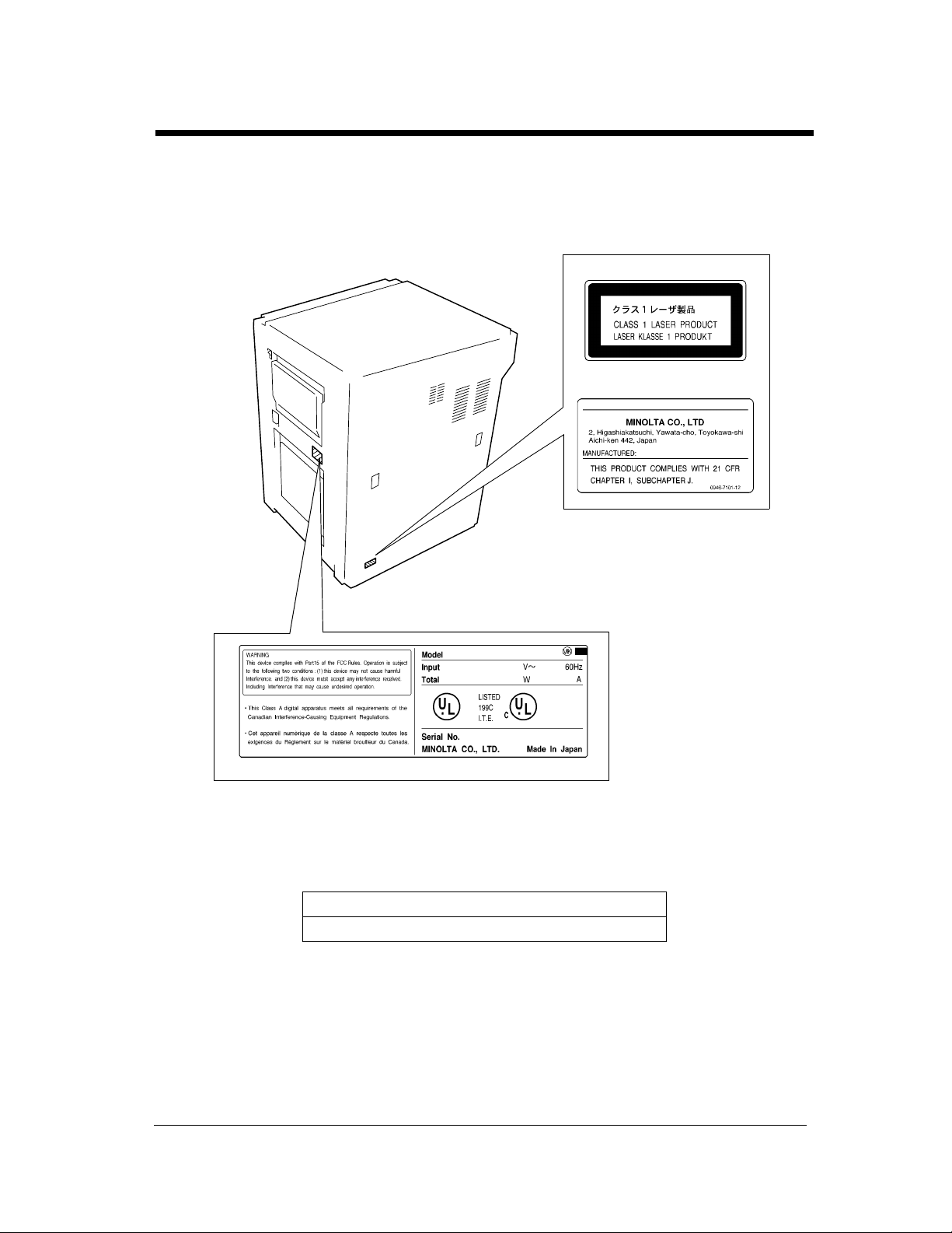
Laser Safety Label
A laser safety label is attached to the outside of the printer as shown below.
For Europe
For United States
v
Safety Precautions
1155O698CB
4115O003AA
1155O699EB
The Manufacturer’s Name Plate is affixed at the position illustrated above.
Please write down the Model Name and Serial No. of your printer here.
Model:
Serial No.
Di620PE Operator’s Manual

vi
Regulatory Information
For United States Users:
WA R N I N G
This equipment has been tested and found to comply with the limits for a Class A digital device, pursuant
to Part 15 of the FCC Rules. These limits are designed to provide reasonable protection against harmful
interference when the equipment is operated in a commercial environment. This equipment generates,
uses, and can radiate radio frequency energy and if not installed and used in accordance with the
instruction manual, may cause harmful interference to radio communications. Operation of this
equipment in a residential area is likely to cause harmful interference in which case the user will be
required to correct the interference at his own expense.
The design and production of this unit conforms to FCC Regulations, and any changes or modifications
must be registered with the FCC and are subject to FCC control. Any changes made by the purchaser or
user without first contacting the manufacturer will be subject to penalty under FCC regulations.
FCC-F01
For Canada Users:
This Class A digital apparatus complies with Canadian ICES-003.
Cet appareil numérique de la classe A est conforme à la norme NMB-003 du Canada.
IC-F03
Di620PE Operator’s Manual
vii
Regulatory Information
For European Users:
Thank you for choosing Minolta.
This operator's manual explains how to operate the printer and replenish its supplies. It also gives some
troubleshooting tips as well as general precautions to be observed when operating the printer.
To ensure the best performance and effective use of your printer, read this manual carefully until you
familiarize yourself thoroughly with its operation and features. After you have read through the manual,
keep it for ready reference.
Please use this manual as a quick and handy reference tool for immediately clarifying any questions
which may arise.
CE Marking (Declaration of Conformity)
We declare under our sole responsibility that the printer and options to which this declaration relates is in
conformity with the specifications below. This declaration is valid for the area of the European Union
(EU) only.
Product Type Console Type Printer
Product Name Di620PE
Options FN-3, FN-102, FN-502, C-304, C-304L, D-102, DT-103, Hard Disk Drive Kit
Accessories 16 MB Memory
Standards Safety *2 : EN 60 950 / 1992 (A1, A2, A3, A4)
(Safety of information technology equipment, including electrical business
equipment)
EN 60825/1992 (A11:1996)
(Safety of laser products-Part 1: Equipment classification, requirements
and users guide)
EMC *1 : EN 55 022 (Class B) / 1994 (A1, A2)
(Limits and method for measurement of radio disturbance characteristics of
information technology equipment (ITE))
EN61000-3-2 / 1995
(Electromagnetic compatibility (EMC) - Part 3: Limits, Section 2: Limits
for harmonic current emissions (equipment input current 16A per phase))
EN61000-3-3 / 1995
(Electromagnetic compatibility (EMC) - Part 3: Limits, Section 3:
Limitation of voltage fluctuations and flicker in low-voltage supply
systems for equipment with rated current 16A)
EN 50 082-1 / 1992
(Electromagnetic compatibility - Generic immunity standard
Part 1: Residential, commercial and light industry)
IEC 801-2 / 1991 (Electrostatic discharge requirement)
IEC 801-3 / 1984 (Radiated electromagnetic field requirement)
IEC 801-4 / 1988 (Electrical fast transient / burst requirement)
Notes : *1) EMC performance: This product was designed for operation in a typical
office environment.
*2) First year of labeling according to EC-directive 73/23/EEC and 93/68/
EEC: 98
3) This product was designed for operation in a typical office environment.
EC Directives Safety : 73 / 23 / EEC and 93 / 68 / EEC
EMC : 89 / 336 / EEC and 93 / 68 / EEC
<
=
<
=
Di620PE Operator’s Manual

viii
Technical Support
For United States and Canada Users:
Thank you for choosing Minolta quality. For over 30 years Minolta has been a leader on the forefront of
office equipment technology and service. Our desire has always been to bring you highly reliable
products. We pledge to continue to provide you, our customer, with our state of the art equipment, as well
as full customer service for all our products. We look forward to a long healthy relationship with you and
our company. If you have any questions or comments about Minolta, our product or service, please let us
know. Our fax number is 800-237-8087 (for U.S.A. and Canada). Thank you again.
This operator’s manual explains how to operate the printer and replenish its supplies. It also gives some
troubleshooting tips as well as general precautions to be observed when operating the printer.
To ensure the best performance and effective use of your printer, read this manual carefully until you
familiarize yourself thoroughly with it’s operation and features. After you have read through the manual,
keep it ready for reference.
Please use this manual as a quick and handy reference tool for immediately clarifying any questions
which may arise.
MC-F01
Di620PE Operator’s Manual
Terms and Symbols for the Type of document and Paper
A few special terms and symbols are used in this manual to designate types of paper. This page explains
about these terms and symbols.
Feeding Direction (paper path)
In this printer system, paper is taken up from the right-hand side of the printer and fed through the printer
toward the left-hand side, face up onto the Tray. In the figure below, the direction in which the paper is
fed, as indicated by the arrow, is called the “feeding direction.”
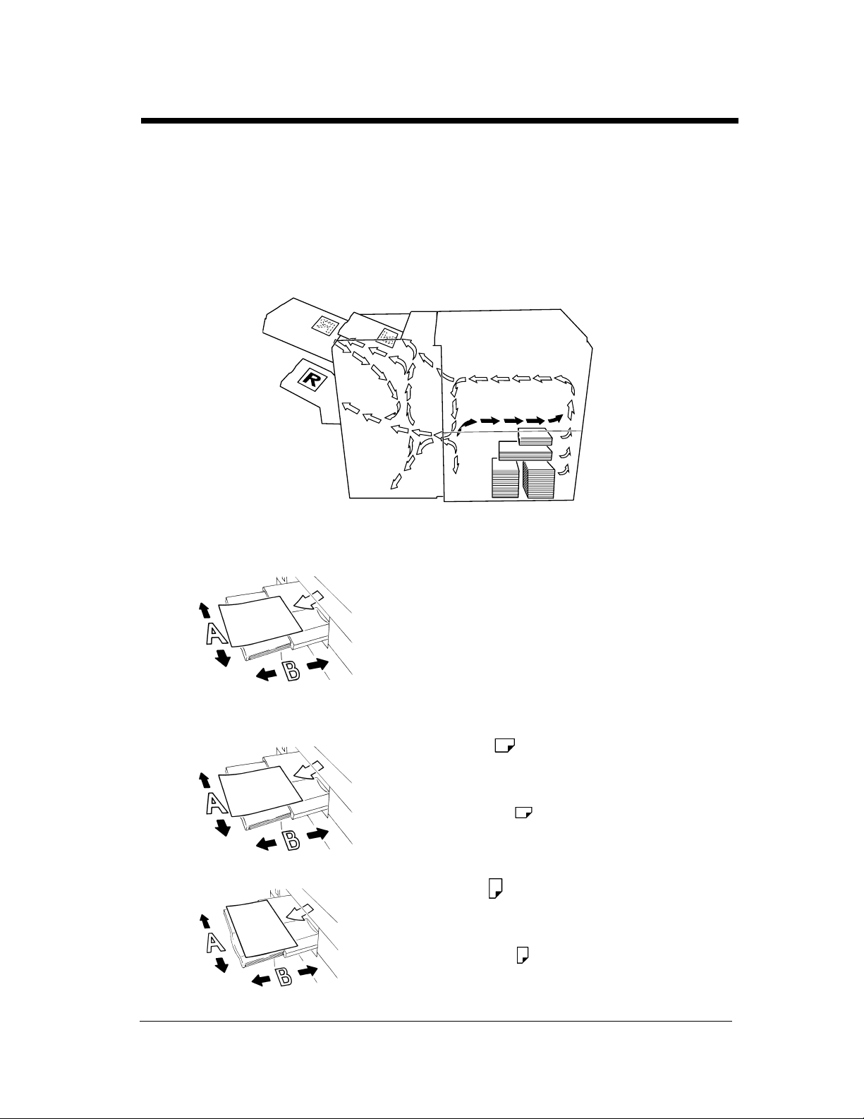
ix
“Width” and “Length”
1139O1610A
Terms and Symbols Used
1139O1610A
4115O002AA
When we talk about the size of the document or
paper, we call side A “width” and side B “length.”
A: Width
B: Length
<Lengthwise >
When the document or paper has a “length” longer
than its “width,” we call it “lengthwise” and use
symbol “L” or “ .”
<Crosswise >
Di620PE Operator’s Manual
When the document or paper has a “length” shorter
than its “width,” we call it “crosswise” and use
symbol “C” or “ .”
1139O1620A

x
Contents
Using the Printer Properly .................................................................................. i
Safety Precautions .............................................................................................iii
Regulatory Information .....................................................................................vi
Technical Support ...........................................................................................viii
Terms and Symbols for the Type of Originals and Paper ................................. ix
Chapter 1 Safety Notes
1. Installing the Printer
Installation Site ...............................................................................................1-2
Power Source ..................................................................................................1-2
Space Requirements ........................................................................................1-2
2. Precautions for Use
Operating Environment ...................................................................................1-3
Using the Printer Properly ..............................................................................1-3
Moving the Printer ..........................................................................................1-3
Care of Printer Supplies ..................................................................................1-3
Note on Making Multiple Prints .....................................................................1-4
Legal Restrictions on Printing ........................................................................1-4
Chapter 2 Getting to Know Your Printer
1. System Overview
System Overview ............................................................................................2-2
2. Printer Parts and Accessories
Outside the Printer ..........................................................................................2-3
Printer Accessories .........................................................................................2-5
Precautions When Using a Finisher ................................................................2-6
Inside the Printer .............................................................................................2-7
3. Turning ON and OFF
Turning ON and OFF ......................................................................................2-8
When the unit is turned ON ............................................................................2-8
Chapter 3 Printing Procedure
1. Printing & Function Settings
Printing & Function Settings ..........................................................................3-2
2. Basic Printing Overview
Manual Feed Tray ...........................................................................................3-3
3. Selecting the Finishing
Selecting the Finishing Function ....................................................................3-5
Auto Dual Function ......................................................................................3-12
Note on Stapling ...........................................................................................3-14
Chapter 4 When a Message Appears
1. When the Message “The current Paper Tray is empty.” Appears
Adding paper ...................................................................................................4-2
2. When the Message “Replenish Toner.” Appears
Replacing the Toner Bottle .............................................................................4-6
3. When the Message “The Staple Cartridge is empty.” Appears
Replacing the Staple Cartridge .......................................................................4-8
4. When the Message “A paper misfeed has been detected.” Appears
Misfeed Location Displays ...........................................................................4-12
Di620PE Operator’s Manual

Misfeed Clearing Procedures ....................................................................... 4-14
5. When a Staple Misfeed Occurs
Clearing the Staple Misfeed ......................................................................... 4-30
6. What Does Each Message Mean?
What does each message mean? ................................................................... 4-32
Chapter 5 Troubleshooting
1. When This Type of Print is Produced
When this type of print is produced ............................................................... 5-2
2. The Printer is not Functioning as Designed
The printer is not functioning as designed ..................................................... 5-3
Chapter 6 Miscellaneous
1. Specifications
Specifications ................................................................................................. 6-2
2. Care of the Printer
Cleaning ......................................................................................................... 6-7
3. Function Combination Matrix
Function combination matrix ......................................................................... 6-8
Conditions for Combined Functions .............................................................. 6-8
4. Description of Paper Size Table
Description of paper size table ....................................................................... 6-9
Index
xi
Contents
About this Manual
Di620PE Operator’s Manual

Chapter 1
1-1
Safety Notes Chapter 1
Safety Notes
Di620PE Operator’s Manual
1-2
1. Installing the Printer
Installation Site
To ensure utmost safety and prevent possible malfunction of the printer, install it in a location which
Chapter 1
meets the following requirements.
◆ A place away from a curtain or the like that may catch fire and burn easily.
◆ An area where there is no possibility of being splashed with water or other types of liquid.
◆ An area free from direct sunlight.
◆ A place out of the direct air stream of an air conditioner, heater, or ventilator.
Safety Notes
◆ A well-ventilated place.
◆ A dry place.
◆ A dust-free location.
◆ An area not subject to undue vibration.
◆ A stable and level location.
◆ A place where ammonia or other organic gas is not generated.
◆ A place which does not put the operator in the direct stream of exhaust from the printer.
◆ A place which is not near any kind of heating device.
Power Source
The power source voltage requirements are as follows:
◆ Use a power source with little voltage fluctuation.
Voltage Fluctuation : Within ± 10% (for U.S.A. and Canada)
Specified voltage ± 10% (For EU)
Frequency Fluctuation : Within ± 0.3% (for U.S.A. and Canada)
Specified voltage ± 10% (For EU)
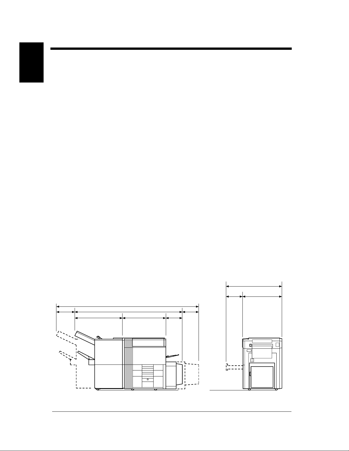
Space Requirements
To ensure easy printer operation, supply replacements, and service maintenance, adhere to the
recommended space requirements detailed below. Allow a clearance of 150mm (6″) or more at the back
of the printer as there is a ventilation duct.
1323 (52)
500
230 (9)
931 (36-3/4)
2831 (111-1/2)
2071 (81-1/2)
735 (29)
405
(11-1/2)
(19-3/4)
530
(16-3/4)
823 (32-1/2)
<With FN-3 and C-304L mounted>
Di620PE Operator’s Manual
4115O004AA
Unit: Metric (Inch)

2. Precautions for Use
Operating Environment
The operating environmental requirements of the printer are as follows:
Temperature : 10°C to 32°C (50°F to 90°F) with a fluctuation of 10°C (18°F) per hour.
Humidity : 15% to 85% with a fluctuation of 10% per hour.
Using the Printer Properly
To ensure optimum performance of the printer, follow the precautions listed below.
◆ NEVER place a heavy object on the printer or subject the printer to shocks.
◆ NEVER open any doors, or turn OFF the printer while the printer is making prints.
◆ NEVER bring any magnetized object or use flammable sprays near the printer.
◆ NEVER remodel the printer, as a fire or electrical shock could result.
◆ ALWAYS insert the power plug all the way into the outlet.
◆ ALWAYS make sure that the outlet is visible, clear of the printer or printer cabinet.
◆ ALWAYS provide good ventilation when making a large number of continuous prints.
NOTE
= Locate the Printer in a Well Ventilated Room =
A negligible amount of ozone is generated during normal operation of this printer. An unpleasant odor
may, however, be created in poorly ventilated rooms during extensive printer operations. For a
comfortable, healthy, and safe operating environment, it is recommended that the room be well
ventilated.
1-3
Safety Notes Chapter 1
REMARQUE
= Placer le Pappareil dans une pièce largement ventilée =
Une quantité d'ozone négligable est dégagée pendant le fonctionnement du l’apparil quand celui-ci
est utilisé normalement. Cependant, une odeur désagréable peut être ressentie dans les pièces dont
l'aération est insuffisante et lorsque une utilisation prolongée du l’apparil est effectuée. Pour avoir la
certitude de travailler dans un environnement réunissant des conditions de confort, santé et de
sécurité, il est préférable de bien aérer la pièce ou se trouve le l’apparil.
Moving the Printer
If you need to transport the printer over a long distance, consult your Technical Representative.
Care of Printer Supplies
Use the following precautions when handling the printer supplies (toner, paper, etc.).
◆ Store the paper, toner, and other supplies in a place free from direct sunlight and away from any heating
apparatus. Keep them in a dry, cool, clean environment.
◆ Store paper, which has been removed from its wrapper but not loaded into the drawer, in a sealed plastic
bag in a cool, dark place.
◆ Keep supplies out of the reach of children.
◆ If your hands become soiled with toner, wash them with soap and water immediately.
Di620PE Operator’s Manual

1-4
2. Precautions for Use
Note on Making Multiple Prints
If the fusing temperature drops excessively during a multi-print cycle, there is a possibility that the
Chapter 1
printing speed will be reduced. The printing speed will automatically return to normal when the fusing
temperature rises enough to ensure good fusing performance.
Legal Restrictions on Printing
Certain types of documents must never be copied by the printer for the purpose or with the intent to pass
Safety Notes
copies of such documents off as the original. The following is not a complete list but is meant to be used
as a guide to responsible printing.
Financial Instruments
• Personal Checks
• Travelers Checks
• Money Orders
• Certificates of Deposit
• Bonds or other Certificates of Indebtedness
• Stock Certificates
Legal Documents
• Food Stamps
• Postage Stamps (canceled or uncanceled)
• Checks or Drafts drawn by Government Agencies
• Internal Revenue Stamps (canceled or uncanceled)
•Passports
• Immigration Papers
• Motor Vehicle Licenses and Titles
• House and Property Titles and Deeds
General
• Identification Cards, Badges, or Insignias
• Copyrighted Works without permission of the copyright owner
In addition, it is prohibited under any circumstances
Art without permission of the copyright owner.
When in doubt about the nature of a document, consult with legal counsel.
Di620PE Operator’s Manual
to print domestic or foreign currencies or Works of

Chapter 2
2-1
Chapter 2Getting to Know Your Printer
Getting to Know Your Printer
Di620PE Operator’s Manual
2-2
1. System Overview
System Overview
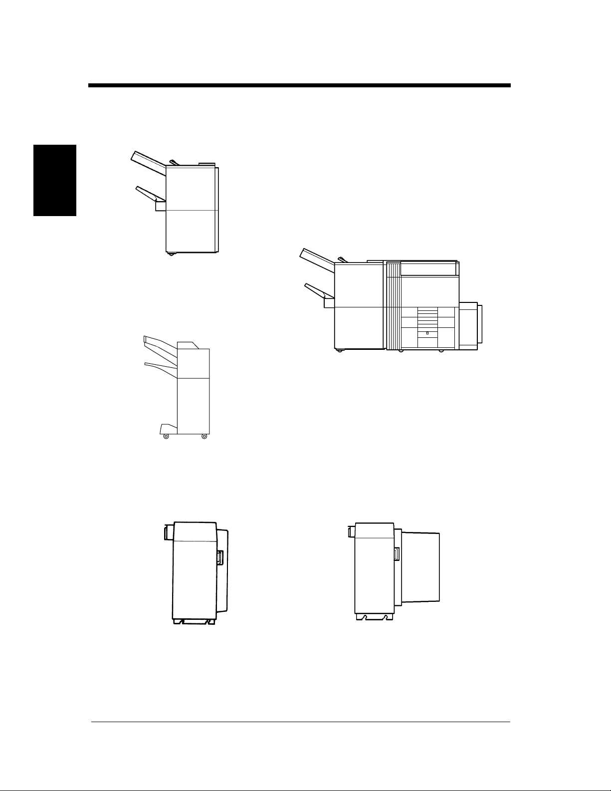
The following overview presents the printer and the available options with a brief explanation of the
function of each. Refer to the separate manual “Print Station Manager Reference Manual”.
Chapter 2
1155O014AA
Finisher FN-3 <Option>
Permits sorting, grouping, sort-stapling,
punching or folding of prints.
Getting to Know Your Printer
1155O730AA
Finisher FN-102 <Option>
Permits sorting, grouping, sort-stapling or
punching of prints.
1134O005AA
Large Capacity Cassette C-304 <Option>
Holds up to 3,400 sheets of A4C, LetterC
paper (80g/m
2
, 20 lbs.).
4115O005AA
1155O721AA
Large Capacity Cassette C-304L <Option>
Holds up to 3,400 sheets of A4L or A4C,
LegalL, LetterL or LetterC, paper (80g/m
2
,
20 lbs.).
Di620PE Operator’s Manual
2. Printer Parts and Accessories
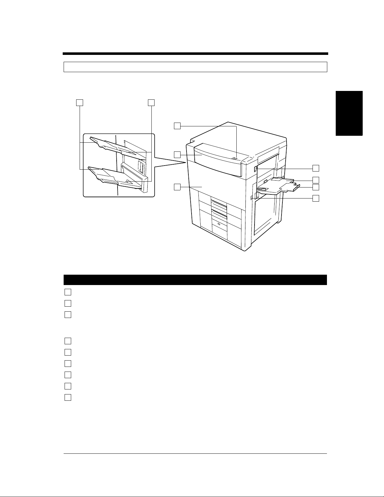
Outside the Printer
1 2
2-3
5
4
3
Printer
1
Exit Tray Extender : Slide this extender out when making prints on large-size paper.
2
Exit Tray : Holds prints fed out of the printer. (Option)
Chapter 2Getting to Know Your Printer
6
7
8
9
4115O006AA
3
Front Door : Open to clear a paper misfeed. ☞p. 4-12
Closing the Front Door after a misfeed has been cleared will turn the
misfeed warning message on the control panel OFF.
4
Upper Front Door : Open to replace the Toner Bottle. ☞p. 4-6
5
Indicator : Green means “Ready”, red means “Paper Misfeed”.
6
Power Switch : Use to turn the pirnter ON and OFF. ☞p. 2-8
7
Manual Feed Tray : Use for manual feeding of paper into the printer. ☞p. 3-3
8
Extender : Slide this extender out to make prints on large-size paper.
9
Total Counter : Shows the total number of prints made so far.
Di620PE Operator’s Manual
2-4
2. Printer Parts and Accessories
Chapter 2
Getting to Know Your Printer
13
10
11
12
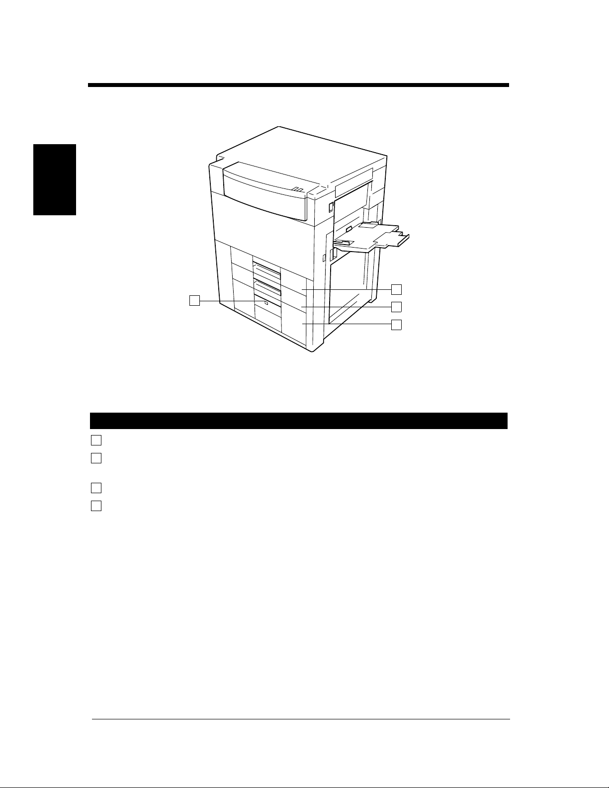
Drawers of the Printer
10
Tray 1 : Holds up to 550 sheets of paper. ☞p. 4-2
11
Tray 2 : Holds up to 550 sheets of paper. ☞p. 4-3
It can accommodate paper of different sizes.
12
Tray 3 : Holds up to 2,700 sheets of paper. ☞p. 4-4
13
Paper Descent Key : Press before sliding the drawer out of the printer.
4115O007AB
Di620PE Operator’s Manual
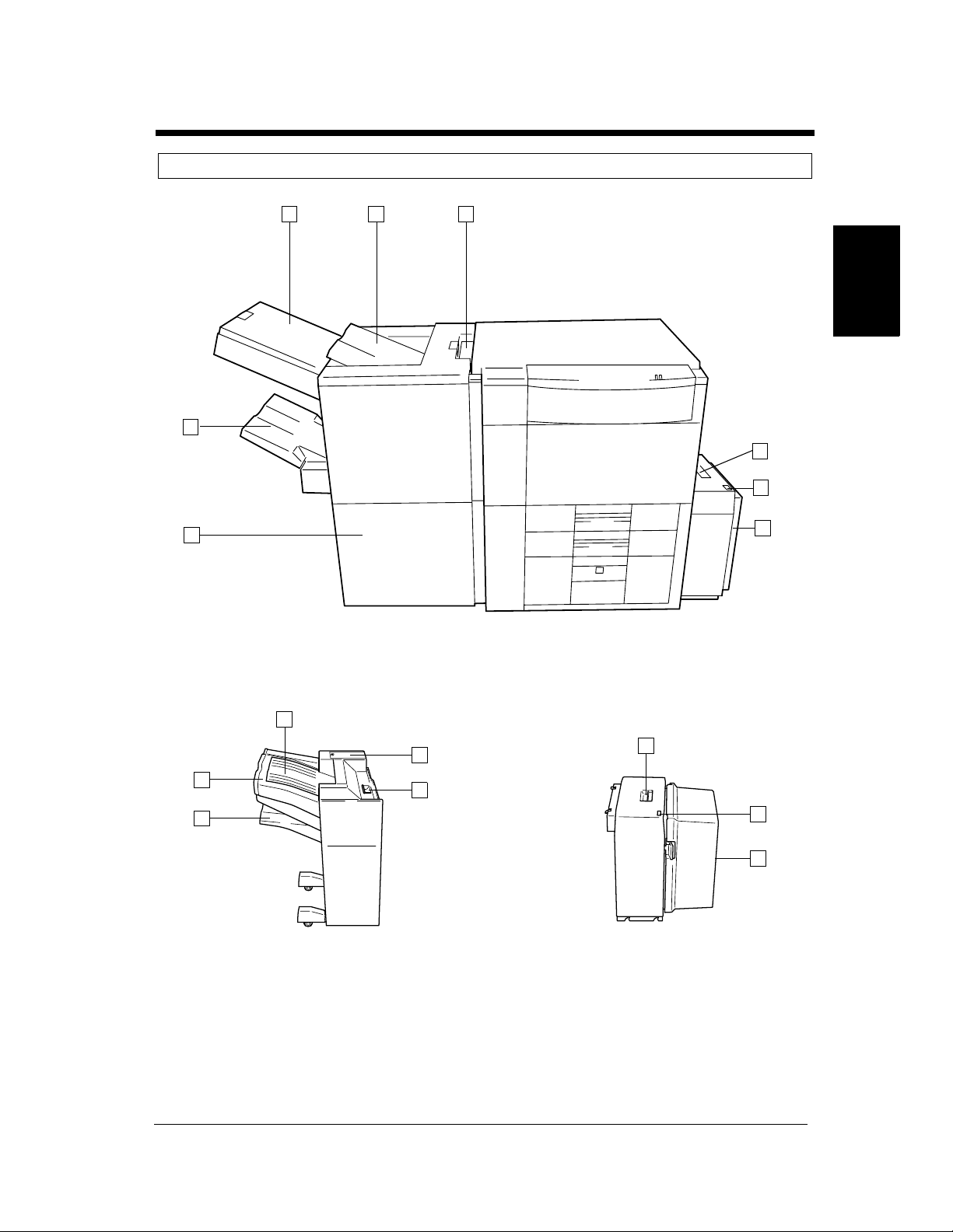
Printer Accessories
1 2 3
8
2-5
2. Printer Parts and Accessories
Chapter 2Getting to Know Your Printer
4
5
7
4115O008AB
6
FN-3 LCC C-304
11
14
15
10
12
13
9
16
1155O732AB
1155O734AB
FN-102 LCC C-304L
Di620PE Operator’s Manual
2-6
2. Printer Parts and Accessories
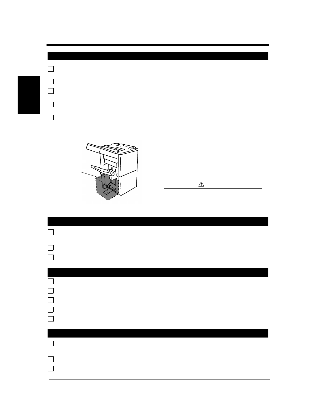
Finisher FN-3
1
Manual Staple Tray : Open to load documents for manual stapling or to clear a paper misfeed.
Cover
2
Top Offset Tray : Receives sorted print sets or grouped print stacks.
3
Grip : Grasp and press here to slide the Finisher away from the printer to clear a
misfeed or other service job.
Finisher Door : Open to replace the Staple Cartridge. ☞p. 4-8
7
Chapter 2
Open to clear a paper misfeed. ☞p. 4-12
Bottom Offset Tray : Receives sorted/stapled print sets or grouped print stacks.
8
Precautions When Using a Finisher
Do not place an
object here.
Getting to Know Your Printer
1155O720AA
NEVER place an object under the Bottom
Offset Tray or Elevator Tray. Anything that is
placed under the Bottom Offset Tray or
Elevator Tray can interfere with the tray when
it lowers after a print set has been fed onto it,
which results in a malfunction.
CAUTION
Do not stack more than 2000 sheets of
paper on the Finisher’s Elevator Tray or risk
damaging the elevator mechanism.
Large Capacity Cassette C-304
Lock Release Lever : Use to unlock the Cassette from the printer for clearing a misfed sheet of
4
paper or other service job.
5
Paper Plate Descent Key : Press to lower the paper plate.
6
Cassette Door : Open to add paper or clear a misfed sheet of paper.
Finisher FN-102
9
Elevator Tray : Receives sorted paper by shifting.
10
Top Offset Tray : Receives plain paper or exclusive paper fed out.
11
Misfeed Clearing Guide : Open to clear misfed paper.
12
Stapler Cover : Open to replace the staple cartridge.
13
Lock Release Lever : Hold to slide the Finisher away from the printer.
Large Capacity Cassette C-304L
14
Lock Release Lever : Use to unlock the Cassette from the printer for clearing a misfed sheet of
paper or other service job.
15
Paper Plate Descent Key : Press to lower the paper plate.
16
Cassette Door : Open to add paper or clear a misfed sheet of paper.
Di620PE Operator’s Manual
Inside the Printer
2-7
2. Printer Parts and Accessories
Chapter 2Getting to Know Your Printer
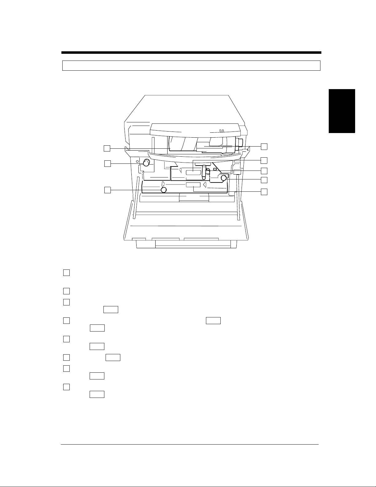
1
8
7
Toner Bottle : Contains Toner. Replace it with a new one when the warning message
1
M1
M5
D2
D1
M7
M4
M3
4115O009AB
2
3
4
5
6
tells you to. ☞p. 4-6
Toner Bottle Holder : Swing open to replace the Toner Bottle. ☞p. 4-6
2
Misfeed Removal : Use to clear a misfed sheet of paper. ☞p. 4-14
3
Guide Unit
Misfeed Removal : Press down to pull out the Unit. ☞p. 4-14
4
Lever
M5
M5
M4
Misfeed Removal : Use to clear a misfed sheet of paper. ☞p. 4-14
5
Knob
Duplex Unit : Slide out to clear a sheet of paper misfed in the Duplex Unit. ☞p. 4-16
6
Misfeed Removal : Use to clear a misfed sheet of paper. ☞p. 4-14
7
Knob
Misfeed Removal : Turn to clear a misfed sheet of paper. ☞p. 4-14
8
Knob
M3
D2
D1
M1
Di620PE Operator’s Manual
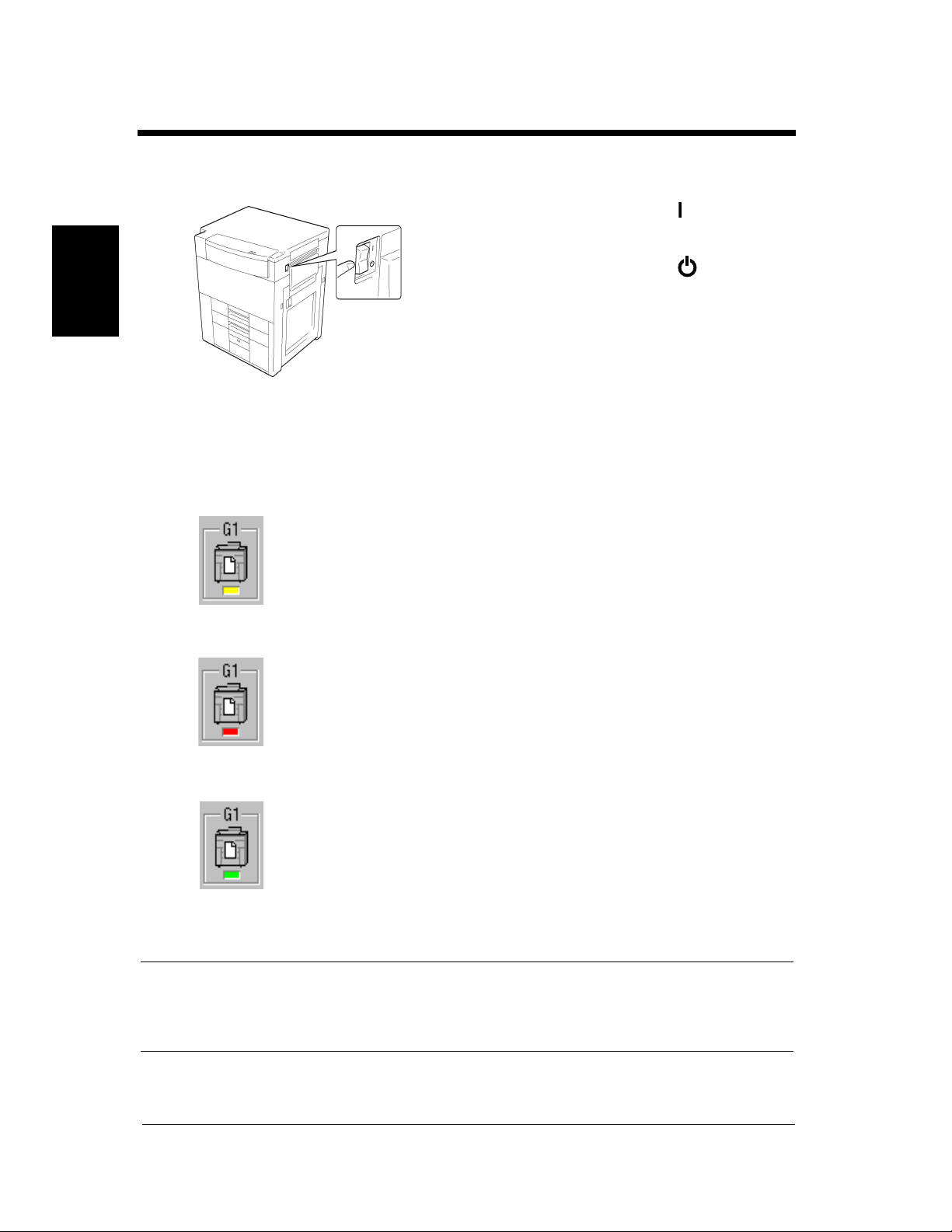
2-8
3. Turning ON and OFF
Turning ON and OFF
• Turning the Printer ON:
Press the Power Switch to the (ON) position.
• Turning the Printer OFF:
Press the Power Switch to the (OFF)
position.
Chapter 2
4115O050AB
When the unit is turned ON
The printer icon on the print station manager screen changes as follows when the power is turned ON.
(1) While the printer is performing a self-test operation during warm-up, or is off-line, busy or in sleep
mode, the icon will turn yellow. The power indicator (green) on the panel will be blinking.
Getting to Know Your Printer
(2) If a printer system error occurs, the icon will turn red. The error indicator (red) on the panel will be
blinking.
• Click this icon to display any current error messages on the
Summary page of the printer driver screen.
• If the icon is red with black stripes, the Di620PE is powered
off.
(3) When the printer enters the print-ready state, the icon will turn light green. The power indicator
(green) on the panel will be on.
• If the icon is dark green, the PlintLink is powered off or the
interface is disconnected.
However, the printing operation cannot be performed even if data from the computer is sent at this time.
A warm-up time of approximately seven minutes (at a room temperature of 20ºC (68ºF)) is required
before printing can be performed.
NOTE
If the fusing temperature drops excessively during a multi-print cycle, there is a possibility that the
printing speed will be reduced. The printing speed will automatically return to normal when the fusing
temperature rises enough to ensure good fusing performance.
Di620PE Operator’s Manual

Panel Indicator
2-9
3. Turning ON and OFF
Power Indicator Error Indicator
Green Red
4115O057AA
Indicator Meaning
Power Indicator ON: Print engine is in the ready state.
Blinking: warming up.
Slow Blinking: Power save mode.
Error Indicator ON: Printing error, fatal error, paper misfeed, something that
prevents printing has occured.
Blinking: Maintenance call.
Chapter 2Getting to Know Your Printer
Di620PE Operator’s Manual

2-10
3. Turning ON and OFF
Chapter 2
Getting to Know Your Printer
Di620PE Operator’s Manual

Chapter 3
3-1
Chapter 3Printing Procedure
Printing Procedure
Di620PE Operator’s Manual

3-2
1. Printing & Function Settings
Printing & Function Settings
Refer to the following manuals for the procedure about printing and/or function settings.
◆ PrintStation Manager Reference Manual
◆ PrintStation Manager Configuration Reference Manual
◆ Raster Image Processor Reference Manual
◆ MicroSpool Reference Manual
◆ MicroSpool Configuration Reference Manual
Chapter 3
Printing Procedure
Di620PE Operator’s Manual

2. Basic Printing Overview
2
Manual Feed Tray
• Use the Manual Feed to make prints on paper not loaded in any tray, or to print onto OHP
transparencies, thick paper, or any other special paper.
• When using the Manual Feed Tray, you can load multiple sheets of paper.
• The setting of paper size is needed for manual feed printing.
• Manual Feed cannot be used for a reserved job.
Paper that Can be Used for Manual Feed Tray
◆ Types of Paper
• Plain paper (weighing 60 g/m
• Thick paper (weighing 91 g/m
• Recycled paper, OHP transparencies
◆ Paper Size
• Max. Size : A3, 11-3/4″
• Minimum Size : A6, 4″
◆ Capacity of the Manual Feed Tray
• Plain paper, Recycled paper⋅⋅⋅Up to 50 sheets
• Plain paper (once-copied paper)⋅⋅⋅Up to 20 sheets
• Thick paper, OHP transparencies⋅⋅⋅Up to 20 sheets
×
5-3/4″
2
to 90 g/m2, 16lbs. to 24 lbs.)
2
to 157 g/m2, 24-1/4 lbs. to 41-3/4 lbs.)
×
17″
3-3
Chapter 3Printing Procedure
Using the Intelligent Manual Feed Tray
Swing down the Manual Feed Tray and insert
1
a neat stack of paper into the tray until it
stops.
*Slide the Tray Extender out when using
large-size paper.
1075O025AB
Slide the Paper Guide Plate to the size of the
paper.
1075O024AB
NOTES
• The paper should be loaded no higher than
the ▼ (Max. Level Indicator).
• Before inserting, fan the paper stack well if
you are using OHP transparencies.
• Correct any curl if you are using thick paper.
• For making prints on thick paper or OHP
transparencies, the following functions cannot
be used: Staple, Hole Punch, Folding Options.
• The paper will be printed on the side facing
up.
Di620PE Operator’s Manual

3-4
3. Selecting the Finishing
In the following, we explain about different finishing functions and setting procedures.
For more infomation on finishing function settings and options, please refer to the PrintStation Manager
Reference Manual.
Staple
<Only when the Finisher is mounted>
• This function is effective when making multiple
printings of a multipage document. Prints are
sorted or grouped into complete sets of the jobs
and then stapled.
• Only when the Finisher FN-3 is mounted, this
feature is efficient for stapling document sets
after making prints.
Chapter 3
1151O108AA
Hole Punch
<Only when the Finisher is mounted>
• Holes are punched in the print sets or stacks for
filing. It can be combined with Non-Sort, Sort,
Printing Procedure
Group or Staple.
Folding
Di620PE Operator’s Manual
1149O398EA
<Only when the Finisher FN-3 is mounted>
• This function allows you to fold prints.
You have a choice of folding options, either
Crease, Half-Fold or Z-fold.
1155O031AA

Selecting the Finishing Function
Sort/Group
Select the desired finishing function.
1
Refer to the printer driver manual
(PrintStation Manager Reference Manual)
for a detailed description of the setting
procedures and setting items.
NOTES
• When the Finisher FN-102 is installed, prints
are fed out in a sawtooth manner in Sort or
Group mode.
• When the Finisher FN-3 is installed, sorted
sets and grouped stacks are separated by a
separator page.
• When a Finisher is not installed, sorted sets
and grouped stacks are separated by a
separator page.
3-5
3. Selecting the Finishing
Useful Tips
• Shift Sorting
The sorted print sets are stacked in the same
direction, but in a sawtooth manner by
shifting the tray to the front or rear for each
set.
Chapter 3Printing Procedure
1166O033AB
• Shift Grouping
The grouped print stacks are stacked in the
same direction, but in a sawtooth manner by
shifting the tray to the front or rear for each
stack.
1166O035AB
Di620PE Operator’s Manual

3-6
3. Selecting the Finishing
Hole Punch
Select the desired finishing function.
1
Refer to the printer driver manual
(PrintStation Manager Reference Manual)
for a detailed description of the setting
procedures and setting items.
NOTES
• The size of the paper for Hole Punch is
11″×17″L, LegalL, LetterL, LetterC, A3L,
A4L and A4C only.
• Hole Punch is not possible in the Interrupt
mode.
• When making prints in the Hole Punch Mode,
Chapter 3
Printing Procedure
make sure of the correct document
orientation.
<Only when the Finisher FN-3 is mounted>
• The number of punch holes can be changed
between “2-Hole” and “3-Hole” by using the
Knob located inside the Finisher.
*When changing the setting for the number of
holes to be made, be sure the marks are
aligned.
Useful Tips
• If you do not select a hole-punching position,
the printer automatically sets the Hole Punch
position according to the document
orientation illustrated below.
On Screen
On Screen
Print
1155O789EA
Print
1155O790EA
• When making prints from either the 11″×17″
or LegalL, A3L or B4L size, the printer
automatically specifies the hole punching
position as shown below.
On Screen
Print
Knob
1155O723AA
Pull out Knob: 2-Hole
Push in Knob: 3-Hole
*The number of punch holes can be graphically
identified on the Display.
1155O791EA
Di620PE Operator’s Manual

Staple
You have a choice of the following two
stapling types.
4115O054CA
*When you touch a stapling key, the finisher
is automatically set into the Sort mode.
3-7
3. Selecting the Finishing
Chapter 3Printing Procedure
Useful Tip
Paper size: A3L to A4, 11″×17L″ to Letter
Number of sheets: 2 to 50
Kinds of Paper: Plain paper, Recycled paper
Di620PE Operator’s Manual

3-8
3. Selecting the Finishing
Manual Staple
<Only with the Finisher FN-3>
Open the Manual Staple Tray Cover.
1
Chapter 3
Align the sheets of paper neatly.
2
Printing Procedure
1155O033AA
1134O039AA
Slide the Paper Guide Plate to the size of the
4
paper.
1155O034AA
NOTE
Make sure that the Paper Guide Plates are in
touch with the edge of the paper stack.
Close the Manual Staple Tray Cover.
5
Insert a neat stack of papers face down into
3
the Staple Tray.
1155O036AB
NOTES
• Make sure of the stapling position and press
the paper stack against the end bracket.
• Up to 50 sheets of plain paper can be stapled.
After you hear the mechanism stop, select
6
the desired stapling type on the Finisher
Panel.
1155O035AA
1155O037AA
Di620PE Operator’s Manual

You have a choice of the following three
stapling positions.
Press . This staples the paper stack or
7
set.
3-9
3. Selecting the Finishing
Chapter 3Printing Procedure
4115O055CA
1155O038AA
Useful Tip
This feature is useful for stapling document sets
after making prints.
Open the Manual Staple Tray Cover and
8
remove the stapled paper stack.
1155O760AA
Close the Manual Staple Tray Cover.
9
Di620PE Operator’s Manual

3-10
3. Selecting the Finishing
Folding
<Only with the Finisher FN-3>
<Crease>
Crease makes a crease in the print at its center
before it is fed out.
1155O039AA
Sizes of paper that can be loaded:
Chapter 3
NOTE
Even if Staple is previously set to a corner or side position, the setting of Crease automatically cancels
this setting and reselects a center stapling position.
A3L, B4L, A4L, 11″×17″L, LetterL
Make sure to select the correct stapling function
when making prints with the Crease function if
you want to make a stapled print set.
<Half-Fold>
Half-Fold folds the print in two at its center with
the print surface on the outside.
Printing Procedure
ex.) A3→A4,
11
″×17″
→
Letter
1155O041AA
You can produce a document that looks like below
by combining this function with Staple and Hole
Punch.
Sizes of paper that can be loaded: 11″×17″L, A3L,
B4L
*The finished print size has a length half that of
Number of sheets: 2~10
the paper loaded in the printer.
NOTE
Even if Staple is previously set to a corner or center position, the setting of Half-Fold automatically
cancels this setting and reselects a side stapling position.
1155O640EA
Di620PE Operator’s Manual

3. Selecting the Finishing
<Z-Fold>
Z-Fold folds the print into three parts with the
print surface inside as shown below.
→
ex.) 11″×17
A3→A4
Sizes of paper that can be loaded: 11″×17″L, A3L
*The finished print size has a length half that of
the paper loaded in the printer.
″
Letter,
1155O043AA
1155O642EA
Number of sheets: 2~10.
NOTES
• Even if screen settings are made to make 2-sided prints, the prints to be Z-Folded will be 1-sided.
• Even if Staple is previously set to center position, the setting of Z-Fold automatically cancels this
setting and reselects a side stapling position.
3-11
Chapter 3Printing Procedure
Di620PE Operator’s Manual

3-12
3. Selecting the Finishing
Auto Dual Function
Auto Dual Function in Finishing Mode
<Only when the Finisher FN-3 is mounted>
Though the Top Offset Tray can hold only up to 100 sheets, the Auto Dual function permits making prints
of up to 2,100 sheets.
Inch Areas
Chapter 3
Sort
Group
Staple
Printing Procedure
Crease
HalfFold
Folding
ZFold
Non-Sort
Sort
Group
Crisscross Sort
Corner
Side
Center
Staple
Non-Sort, Sort,
Group
Staple
Non-Sort, Sort,
Group
Staple
Paper Size
LetterC
11 by 17L, LegalL,
LetterL
5.5 by 8.5L,
5.5 by 8.5C
LetterL, LetterC
11 by 17L to Letter
LetterC
11 by 17L, LegalL,
LetterL
11 by 17L, LetterL
11 by 17L, LetterL
11 by 17L
11 by 17L
11 by 17L
11 by 17L
To p
Offset
Tray
100 sheets
100 sheets
100 sheets
100 sheets
- 100 sets or 1000 sheets -
- - 200 sets or 2000 Sheets
- - 200 sets or 1000 Sheets
- - 100 sets or 1000 sheets
- - 100 sets or 1000 sheets
10 sheets
-
10 sheets
-
Corner Staple 2-Point Staple
Bottom Offset Tray
2000 sheets (no staple)
1000 sheets (no staple)
-
1000 sheets (no staple)
50 sheets (no staple)
- 100 sheets
50 sheets (no staple)
100 sheets 100 sheets
Di620PE Operator’s Manual

Metric Areas
3-13
3. Selecting the Finishing
Non-Sort
Sort
Group
Crisscross Sort
Sort
Group
Staple
Crease
HalfFold
Folding
ZFold
Non-Sort, Sort,
Non-Sort, Sort,
Corner
Side
Center
Staple
Group
Staple
Group
Staple
Paper Size
A4C
A3L, B4L, A4L
A5L, A5C, A6L
A4L, A4C
A3L to A4
A4C
A3L, B4L, A4L
A3L to A4L
A3L to A4L
A3L to B4L
A3L to B4L
A3L
A3L
To p
Offset
Tra y
100 sheets
100 sheets
100 sheets
100 sheets
- 100 sets or 1000 sheets -
- - 200 sets or 2000 Sheets
- - 200 sets or 1000 Sheets
- - 100 sets or 1000 sheets
- - 100 sets or 1000 sheets
10 sheets
-
10 sheets
-
Corner Staple 2-Point Staple
Bottom Offset Tray
2000 sheets (no staple)
1000 sheets (no staple)
1000 sheets (no staple)
50 sheets (no staple)
- 100 sheets
50 sheets (no staple)
100 sheets 100 sheets
NOTE
When the Finisher FN-102 is mounted, the Auto Dual Function is not available.
-
Chapter 3Printing Procedure
Auto Dual Function in Stapling
If a stapling sequence is attempted and the number of sheets is greater than the stapling capacity, Stapling
is automatically canceled and the Finisher is set into the Sort or Group mode, sorting or grouping prints
using the Auto Dual function (but no stapling action takes place).
Di620PE Operator’s Manual

3-14
3. Selecting the Finishing
Note on Stapling
When prints are made using the stapling function, the stapled print sets may not be neatly stacked on the
tray or may even fall off the tray unless certain conditions are met regarding the number of prints to be
stapled and the number of print sets to be made. Use the following table as guide when making prints.
Print Set Capacity
Chapter 3
No. of Prints Stapled
2 prints 200 sets
3 to 5 prints 150 sets
6 to 10 prints 100 sets
11 to 20 prints 70 sets
21 to 30 prints 53 sets
31 to 40 prints 45 sets
41 to 50 prints 40 sets
When Finisher FN-102 is Mounted
A3L to A4
, 11″×17″L
to Letter
Printing Procedure
Di620PE Operator’s Manual

4-1
Chapter 4
When a Message Appears
Chapter 4When a Message Appears
Di620PE Operator’s Manual

4-2
Ma.
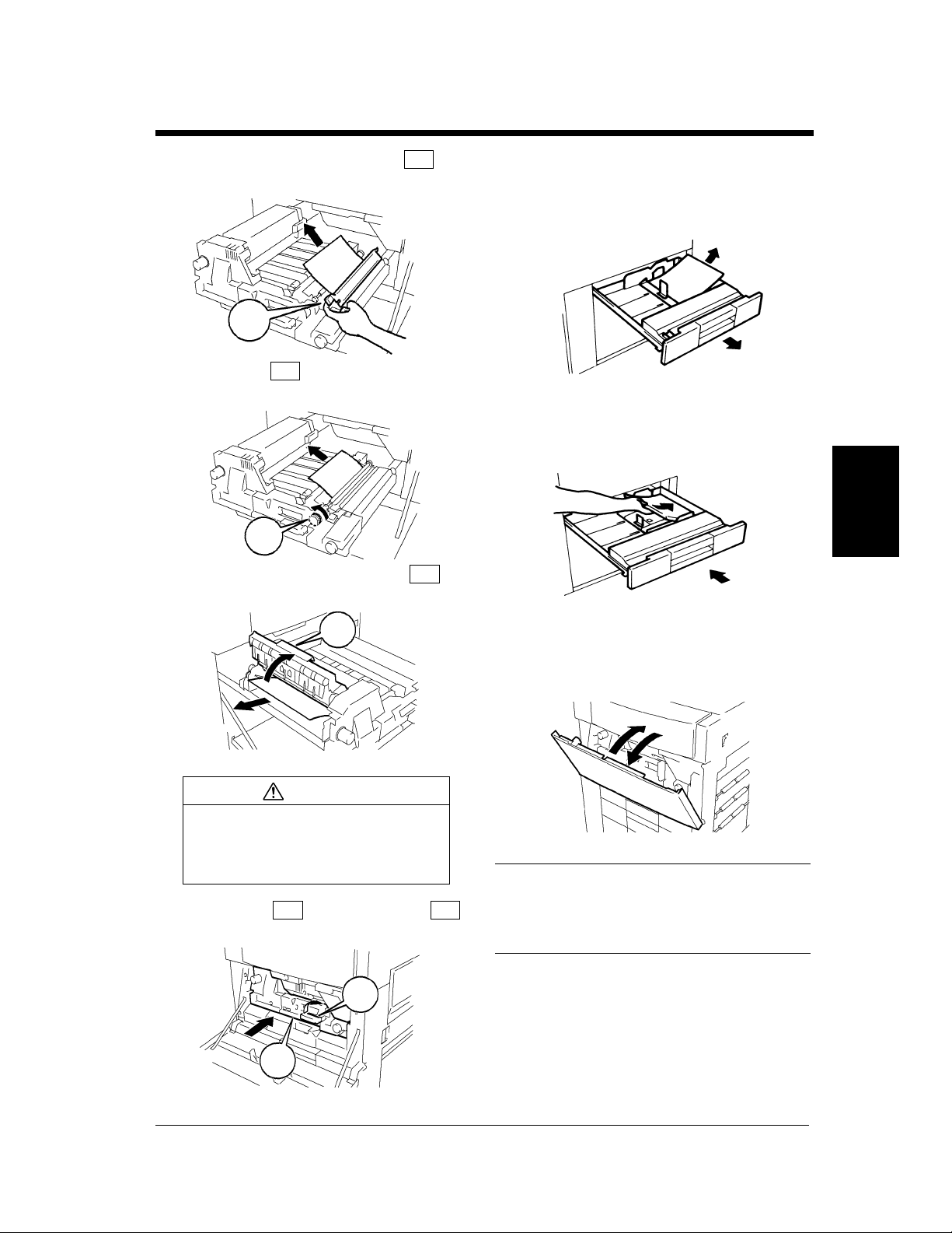
1. When the Message “The current Paper Tray is empty.” Appears
When the tray currently selected for use runs out
of paper, the message shown on the left appears.
The current print cycle is interrupted and you
cannot start a new print cycle. The blinking
drawer has run out of paper.
Adding paper
Tray 1
Slide out Tray 1.
1
Chapter 4
Load the paper stack into the Tray so that its
2
front side faces down.
When a Message Appears
The current Paper Tray is empty.
1075O101DA
Add paper by using the following procedure.
Slide the Tray back in.
3
1161O095DA
1161O009AA
NOTE
The paper should be loaded no higher than the
▼ (Max. Level Indicator).
Ma.
1145O555KA
Di620PE Operator’s Manual

Tray 2
Ma.
4
4-3
1. When the Message “The current Paper Tray is empty.” Appears
Slide out Tray 2.
1
Slide the Edge Guides in the direction of the
2
arrow to suit the paper size.
1161O096DA
1161O097DA
Slide the Tray back in.
1161O104DA
Chapter 4When a Message Appears
Load the paper stack into the Tray so that its
3
front side faces down.
1161O099DA
NOTE
The paper should be loaded no higher than the
▼ (Max. Level Indicator).
Ma.
1145O555KA
Di620PE Operator’s Manual

4-4
r
y
Ma.
1. When the Message “The current Paper Tray is empty.” Appears
Tray 3
Press the Paper Descent Key and then slide
1
the Tray out.
Indication of the Paper Descent Key
Steady Light:
Tray 3 has run out of paper when a Tray
other than the 3rd is currently selected fo
1136O146AA
Chapter 4
1136O145AA
2
use.
Blinking Light
:
Tray 3 has run out of paper when the Tra
3 is currently selected for use.
Load the paper stack into the right half of the
tray, front side face down. Press the leading
edge of the paper stack tightly up against the
right side of the Tray.
1075O049BA
Load another paper stack into the left half of
3
the Tray, front side face down. Press the
leading edge of the paper stack tightly up
against the left side of the Tray.
1161O108DA
NOTE
The paper should be loaded no higher than the
▼ (Max. Level Indicator).
Ma
1161O150AA
Slide the Tray back in and press the Paper
4
Descent Key.
When a Message Appears
1075O052BA
1161O106DA
NOTE
The paper should be loaded no higher than the
▼ (Max. Level Indicator).
Ma.
1145O555KA
Di620PE Operator’s Manual

Large Capacity Cassette
Ma.
3
4-5
1. When the Message “The current Paper Tray is empty.” Appears
Holding the Door Lock Release Lever, open
1
the Cassette Door.
1134O055AA
When adding paper to a partially loaded Cassette,
press the Paper Plate Descent Key to lower the
Paper Plate before opening the Cassette Door.
1134O031AA
Place the paper stack onto the Paper Plate so
2
that its front side faces up.
NOTES
• Make sure that the leading edge of the paper
stack is pressed tightly up against the Guide
Plate on the take-up side of the Cassette.
• The paper should be loaded no higher than
the ▼ (Max. Level Indicator).
Ma.
1145O555KA
Close the Cassette Door.
Chapter 4When a Message Appears
1134O033AA
* This causes the Paper Plate to rise
automatically.
Di620PE Operator’s Manual
NOTE
The Paper Plate may not ascend if the Cassette
Door is not closed completely. Be sure to close
the Door completely.
1134O054AA

4-6
2. When the Message “Replenish Toner.” Appears
The message shown on the left appears when
toner is soon running out. You can still make
prints, but the image density will become lighter
and lighter. It is recommended therefore that you
replace the Toner Bottle as soon as possible.
Replenish Toner
When toner has run out, the message shown on
the left appears and you can no longer start a new
print cycle. Replace the Toner Bottle with a new
one by following the procedure given below.
Chapter 4
Replacing the Toner Bottle
Swing down the Upper Front Door.
1
When a Message Appears
Swing open the Toner Bottle Holder and pull
2
out the used Toner Bottle.
4115O013CA
4115O045AA
Tap a new Toner Bottle against a desk or
3
other hard surface four to five times. Then,
turn the Toner Bottle upside down and tap it
in the same way again.
1075O229AA
Di620PE Operator’s Manual
1075O054AA

4-7
7
2. When the Message “Replenish Toner.” Appears
Shake the new Toner Bottle well and turn it
4
over lengthwise five times.
1075O266AA
With the “UP” marking on top, insert the
5
Bottle into position.
Check that the marking on the Bottle is
aligned with the marking on the Toner
Bottle Holder.
4115O046AA
Swing the Toner Bottle Holder closed and
close the Front Door.
1075O059AA
NOTES
• Use ONLY the specified toner for this printer.
Using any other toner could result in trouble.
• Do not throw away, but keep, the used Toner
Bottle which will be collected by your Tech.
Rep.
• Be careful not to drop the Toner Bottle from a
1 m or more height. It may cause damage to
the Toner Bottle.
• When the Front Door is closed, the printer
automatically starts replenishing the supply of
toner. During this period, do not attempt to
turn OFF the Power Switch or open the Front
Door.
Chapter 4When a Message Appears
Pull the seal off the Toner Bottle.
6
Ton er R ep le n i s he r
Use the Toner Replenisher function available
from the User Mode if the image is light
immediately after the Toner Bottle has been
replaced with a new one.
1075O058AA
Di620PE Operator’s Manual
4-8
3. When the Message “The Staple Cartridge is empty.” Appears
The message shown on the left appears when the
staples are running out.
Replace the Staple Cartridge with a new one by
following the procedure given below.
Replenish Toner
Replacing the Staple Cartridge
<Only when the Finisher FN-3 is mounted>
While pressing down the Staple Cartridge
4
Lever, pull the Staple Cartridge out of its
port.
Chapter 4
Holding the Finisher Lock Release Lever,
1
slide the Finisher away from the printer.
4115O014AA
Open the Finisher Front Door.
2
When a Message Appears
1155O067AA
Slide out the Staple Unit.
3
1155O068AA
Pull the staple sheet about 3 cm out of the
5
new Staple Cartridge and break off that
portion.
1155O069AA
1136O012AA
Di620PE Operator’s Manual

4-9
8
9
10
3. When the Message “The Staple Cartridge is empty.” Appears
NOTE
Check that no portion of the staple sheet hangs
out of the cartridge. Break off any portion of the
sheet that hangs out of the cartridge.
1134O076AA
Insert the new Staple Cartridge until it clicks
6
into position.
1155O070AA
Push the Staple Unit back in and close the
7
Finisher Front Door.
Slide the Finisher back against the printer.
4115O015AA
Test the stapler by placing a sheet of paper
into the Manual Staple Tray (see p. 3-8).
Press the key.
Chapter 4When a Message Appears
1155O038AA
Remove the sheet of paper to check that it
has been properly stapled.
* If no staples are evident, repeat the procedure
from the beginning.
Di620PE Operator’s Manual
1155O071AA
1155O644AC
NOTES
• Replace the Staple Cartridge only after you
are prompted to do that by the message.
Removing the Staple Cartridge before then
will result in stapling trouble.
• After a new Staple Cartridge has been
installed, be sure to run a test-stapling
sequence to ensure that staples are properly
driven into the paper.

4-10
3. When the Message “The Staple Cartridge is empty.” Appears
<Only when the Finisher FN-102 is mounted>
Press and turn the knob and open the cover at
1
the rear of the Finisher.
Pull the Stapler Unit out of the well.
2
Chapter 4
While pressing down the green lever, pull out
3
the Staple Cartridge.
1155O766AA
1166O127AA
Remove the empty staple clip from the
4
Staple Cartridge.
Load a new staple clip into the Staple
5
Cartridge and carefully peel off the Seal.
Insert the Staple Cartridge into the Stapler
6
Unit until it clicks into place.
1166O129AA
1166O161AD
When a Message Appears
Di620PE Operator’s Manual
1166O128AA
Align the arrows and firmly push the Stapler
7
Unit down into the well.
1166O130AB
1166O131AB

Press and turn the Knob to lock the cover.
8
1155O767AA
NOTES
• Replace the Staple Cartridge only after you
are prompted to do that by the message.
Removing the Staple Cartridge before then
will result in stapling trouble.
4-11
3. When the Message “The Staple Cartridge is empty.” Appears
Chapter 4When a Message Appears
Di620PE Operator’s Manual

4-12
4. When the Message “A paper misfeed has been detected.” Appears
If a paper misfeed occurs during a print cycle, the
message shown on the left appears and that
particular print cycle is stopped in the middle of
operation.
Clear the misfed sheet of paper according to the
procedure given below.
4115O016CA
Misfeed Location Displays
Different procedures are used to clear a misfed sheet of paper depending on the location. First, isolate the
location, then clear the misfeed according to the procedure applicable to the misfeed occurring at that
particular location. A blinking dot “ ” indicates that there is a misfeed at that location. A lit dot “ ”
indicates that there might be a sheet of paper stopped at that location.
When a misfeed occurs, the error indicator (red) on the printer’s front panel will light. This light will go
out whenever the front door is opened.
Chapter 4
Copier p. 4-14
4115O017AA 4115O018AA 4115O019AA 4115O020AA 4115O021AA
When a Message Appears
Duplex Unit p. 4-16
Di620PE Operator’s Manual
4115O020AA4115O023AA4115O022AA

4-13
4. When the Message “A paper misfeed has been detected.” Appears
Large Capacity Cassette p. 4-18 Intelligent Manual Feeding Tray p. 4-19
4115O024AA
Finisher FN-3 p. 4-20
4115O025AA 4115O026AA 4115O027AA 4115O028AA
4115O029AA 4115O030AA 4115O031AA 4115O032AA
Finisher FN-102 p. 4-28
4115O019AA
Chapter 4When a Message Appears
4115O033AA 4115O034AA
Di620PE Operator’s Manual
4115O035AA
4115O036AA

4-14
M5
4. When the Message “A paper misfeed has been detected.” Appears
Misfeed Clearing Procedures
Printer
Chapter 4
Open the Misfeed Clearing Guide ,
1
pull out the sheet of paper.
L1
Open the Left Door.
2
Open the Front Door.
3
L1
1155O558AB
1155O076AA
Open the Right Door.
6
Turning Knob , pull out the sheet of
7
paper.
M2
Close the Right Door.
8
M2
1155O079AA
1155O080AA
Turn Knob to feed the sheet of paper.
9
When a Message Appears
4115O047AA
Turning Knob , pull out the sheet of
4
paper. Then turn Knob to return any
paper to the Duplex Unit.
Close the Left Door.
5
M1
D1
D1
M1
1155O078AA
Lower the Lever and slide out the
10
M3
M3
1155O081AA
M4
Unit.
M4
M5
1155O082AA
Di620PE Operator’s Manual
4-15
15
16
17
18
4. When the Message “A paper misfeed has been detected.” Appears
Raising Misfeed Clearing Guide ,
11
remove the sheet of paper.
M6
Turn Knob and remove the sheet of
12
paper.
Opening Misfeed Clearing Guide ,
13
remove the sheet of paper.
M7
M7
M6
1155O083AA
1155O085AA
M8
Close the Front Door.
Slide out the Tray being used and take out
the paper stack left in it.
1075O068AA
Reload the paper stack and slide the Tray
into the printer.
Chapter 4When a Message Appears
1075O069AA
M8
CAUTION
The area around the Fusing Unit is
very hot. Do not touch anything but
the paper to prevent you from
getting burned.
Slide in the Unit and raise the
14
Lever back up again.
M5 M4
M4
M5
To reset the paper misfeed indication on the
Panel, open and close the Front Door.
1155O084AA
4115O048AA
Useful Tip
After the paper misfeed has been cleared, the
printer automatically resumes a print cycle
without the Start Command.
1155O086AA
Di620PE Operator’s Manual

4-16
4. When the Message “A paper misfeed has been detected.” Appears
Duplex Unit
Chapter 4
Open the Left Door.
1
Open the Front Door.
2
Turning Knob , pull out the sheet of
3
paper. Then turn Knob to return any
paper to the Duplex Unit.
M1
D1
1155O076AA
4115O047AA
Turning Knob , pull out the sheet of
6
paper.
M2
Close the Right Door.
7
Slide out Duplex Unit .
8
Raising Misfeed Clearing Guide ,
9
remove the sheet of paper.
M2
D2
D2
1155O080AA
1155O089AA
D3
When a Message Appears
Close the Left Door.
4
Open the Right Door.
5
Di620PE Operator’s Manual
D1
M1
1155O078AA
1155O079AA
D3
Raising Misfeed Clearing Guide ,
10
remove the sheet of paper.
D4
1155O090AA
D4
1155O091AA

4-17
4. When the Message “A paper misfeed has been detected.” Appears
Raising Misfeed Clearing Guide ,
11
remove the sheet of paper.
Slide Duplex Unit back into the
12
printer.
Close the Front Door.
13
D2
D2
D5
D5
1155O092AA
Chapter 4When a Message Appears
1155O093AA
Useful Tip
After the paper misfeed has been cleared, the
printer automatically resumes a print cycle
without the Start Command.
Di620PE Operator’s Manual

4-18
4. When the Message “A paper misfeed has been detected.” Appears
Large Capacity Cassette
Chapter 4
Press the Paper Descent Key.
1
1134O031AA
Holding the Door Lock Release Lever, open
2
the Cassette Door and remove the sheet of
paper.
1134O027AA
Remove the sheet of paper.
5
Slide the Cassette back against the printer.
6
1134O029AA
1134O030AA
Close the Cassette Door.
3
When a Message Appears
1134O033AA
Press the Lock Release Lever and slide the
4
Cassette away from the printer.
1134O028AA
Di620PE Operator’s Manual

Intelligent Manual Feed Tray
Unload the paper stack from the Manual
1
Feed Tray and open the Right Door.
Pull out the sheet of paper from the Paper
2
Take-Up Section. Then, close the Right
Door.
4-19
4. When the Message “A paper misfeed has been detected.” Appears
1075O071AB
Chapter 4When a Message Appears
Place the paper stack back on the tray.
3
To reset the paper misfeed indication on the
4
Touch Panel, open and close the Front Door.
1155O087AA
1075O073AA
Di620PE Operator’s Manual
4115O048AA

4-20
4. When the Message “A paper misfeed has been detected.” Appears
Finisher FN-3
<When the following dots are lit:>
4115O037AA
Holding the Finisher Lock Release Lever,
1
slide the Finisher away from the printer.
Close the Misfeed Clearing Guide and
4
tighten the screws.
Open the Finisher Front Door.
5
1155O067AA
Chapter 4
When a Message Appears
Opening Misfeed Clearing Guide ,
2
remove the sheet of paper.
FN1
Loosen two screws, open the Misfeed
3
Clearing Guide and remove the sheet of
paper.
4115O014AA
FN1
1155O406AA
Raising Misfeed Clearing Guide ,
6
remove the sheet of paper.
FN3
FN2
FN2
FN4
Turn Knob to feed the sheet of paper.
7
Open Misfeed Clearing Guide .
8
FN3
1155O407AA
1155O408AA
Di620PE Operator’s Manual
1155O700AA
FN4
1155O409AA

4-21
13
14
4. When the Message “A paper misfeed has been detected.” Appears
Remove the sheet of paper and close Misfeed
9
Clearing Guide .
Turn Knobs and to feed the
10
sheet of paper.
FN7
FN6
FN4
FN7
FN4
FN6
1155O410AA
1155O411AA
Close the Finisher Front Door.
1155O645AA
Slide the Finisher back against the printer.
4115O015AA
Chapter 4When a Message Appears
Pinching the lever of Misfeed Clearing
11
Guide , open .
Remove the sheet of paper and close .
12
FN5
FN5
FN5
FN5
1155O412AA
FN5
1155O413AA
Di620PE Operator’s Manual

4-22
FN5
4. When the Message “A paper misfeed has been detected.” Appears
<When the following dots are lit:>
Holding the Finisher Lock Release Lever,
1
slide the Finisher away from the printer.
Chapter 4
Open the Finisher Front Door.
2
4115O038AA
4115O014AA
Remove the sheet of paper and close
4
FN8
.
Turn Knobs and to feed the
5
sheet of paper.
Pinching the lever of Misfeed Clearing
6
Guide , open .
FN7 FN6
FN7
FN6
FN5
FN8
1155O415AA
1155O411AA
When a Message Appears
Pinching the lever of Misfeed Clearing
3
Guide , open .
Di620PE Operator’s Manual
FN8 FN8
FN8
1155O067AA
1155O414AA
FN5
Remove the sheet of paper and close .
7
FN5
1155O412AA
FN5
1155O413AA
4-23
1
2
FN9
3
4
FN10
4. When the Message “A paper misfeed has been detected.” Appears
Close the Finisher Front Door.
8
Slide the Finisher back against the printer.
9
1155O645AA
4115O015AA
<When the following dots are lit:>
4115O039AA
Open Exit Tray and remove the
sheet of paper.
Close .
FN9
FN9
Chapter 4When a Message Appears
1155O424AA
Open Manual Staple Tray Cover
and remove the sheet of paper.
FN10
Close .
FN10
1155O425AA
Di620PE Operator’s Manual

4-24
4. When the Message “A paper misfeed has been detected.” Appears
<When the following dots are lit:>
Holding the Finisher Lock Release Lever,
1
slide the Finisher away from the printer.
Chapter 4
Open the Finisher Front Door.
2
4115O040AA
4115O014AA
Turn Knob to feed the sheet of
4
paper.
Open Misfeed Clearing Guide .
5
Remove the sheet of paper and close Misfeed
6
Clearing Guide .
FN2
FN2
FN4
FN4
1155O408AA
FN4
1155O409AA
When a Message Appears
Raising Misfeed Clearing Guide ,
3
remove the sheet of paper.
FN3
Di620PE Operator’s Manual
1155O067AA
FN3
1155O407AA
FN4
Turn Knobs and to feed the
7
sheet of paper.
FN7 FN6
FN7
FN6
1155O410AA
115 5O4 11AA

4-25
11
12
13
4. When the Message “A paper misfeed has been detected.” Appears
Pinching the lever of Misfeed Clearing
8
Guide , open .
Remove the sheet of paper and close
9
FN5 FN5
FN5
FN5
.
FN5
1155O412AA
1155O413AA
Check to see if a sheet of paper is left in the
Finisher. If any is visible, perform step 10
once again.
1155O719AA
NOTE
Sliding out Paper Folding Unit with a
sheet of paper left inside could result in a
malfunction.
Open Misfeed Clearing Guide .
PF2
FN4
Chapter 4When a Message Appears
Turn Knobs and together five
10
turns to feed the sheet of paper.
FN2 PF1
FN2
PF1
1155O408AA
1155O416AA
FN4
1155O409AA
Remove the sheet of paper and close Misfeed
Clearing Guide .
FN4
FN4
1155O410AA
Di620PE Operator’s Manual

4-26
4. When the Message “A paper misfeed has been detected.” Appears
Chapter 4
Turn Knobs and to feed
14
the sheet of paper.
Pinching the lever of Misfeed Clearing
15
Guide , open .
Remove the sheet of paper and close .
16
FN7 FN6
FN7
FN6
1155O411AA
FN5 FN5
FN5
1155O412AA
FN5
Opening Misfeed Clearing Guide ,
18
remove the sheet of paper.
PF3
Raise Misfeed Clearing Guide .
19
PF4
Turning Knob , remove the sheet of
20
paper and then lower Misfeed Clearing
Guide .
PF4
PF1
PF3
1155O418AA
PF4
1155O419AA
When a Message Appears
Slide out Paper Folding Unit .
17
Di620PE Operator’s Manual
FN5
PF2
PF2
1155O413AA
1155O417AA
PF4
Opening Misfeed Clearing Guide ,
21
remove the sheet of paper.
PF5
PF1
1155O420AB
PF5
1155O421AA

4-27
4. When the Message “A paper misfeed has been detected.” Appears
Opening Misfeed Clearing Guide ,
22
remove the sheet of paper.
PF6
Slide Paper Folding Unit back into
23
the printer.
PF2
PF2
PF6
1155O423AA
Chapter 4When a Message Appears
1155O422AA
Close the Finisher Front Door.
24
Slide the Finisher back against the printer.
25
1155O645AA
4115O015AA
Di620PE Operator’s Manual

4-28
4. When the Message “A paper misfeed has been detected.” Appears
Finisher FN-102
Chapter 4
Holding the Finisher Lock Release Lever,
1
slide the Finisher away from the printer.
If “Hole Punch” has been set, turn the Hole
2
Punch Adjustment Dial ten times upward.
Remove the sheet of paper.
4115O041AA
Open Misfeed Clearing Guide and
4
remove the sheet of paper.
Open Misfeed Clearing Guide and
5
remove the sheet of paper.
FN3
1155O740AA
FN4
1155O741AA
1155O739AA
Open Misfeed Clearing Guide .
3
When a Message Appears
CAUTION
Metallic parts inside Misfeed
Clearing Guide are very hot.
Do not touch anything but the
paper to prevent you from getting
burned.
FN2
FN2
1166O168AA
Raise Misfeed Clearing Guide and
6
remove the sheet of paper.
Close Misfeed Clearing Guide until
7
it clicks into position.
FN5
1155O742AA
FN5
1155O743AA
Di620PE Operator’s Manual

4-29
12
13
14
15
4. When the Message “A paper misfeed has been detected.” Appears
Open Misfeed Clearing Guide and
8
remove the sheet of paper.
Open Misfeed Clearing Guide at the
9
right side of the Finisher.
Remove the sheet of paper.
10
FN9
FN7
1155O744AC
1155O745AB
Close Misfeed Clearing Guide .
Open Misfeed Clearing Guide .
Remove the sheet of paper and close Misfeed
Clearing Guide .
FN1
FN2
1166O172AA
FN1
1166O173AA
Chapter 4When a Message Appears
Close Misfeed Clearing Guide .
11
Di620PE Operator’s Manual
1155O746AC
1166O174AA
FN7
Slide the Finisher back against the printer.
1155O747AA
4115O049AA

4-30
5. When a Staple Misfeed Occurs
Clearing the Staple Misfeed
<Only when the Finisher FN-102 is mounted>
4115O042CA
If a staple misfeed occurs, the message shown on
the left appears.
Clear the staple misfed according to the procedure
given below.
Chapter 4
When a Message Appears
Open Misfeed Clearing Guide .
1
Remove the sheet of paper and close Misfeed
2
Clearing Guide .
Press and turn the knob to open the cover at
3
the rear of the Finisher.
FN1
FN1
1166O174AA
1166O173AA
Pull the Stapler Unit out of the well.
4
While pressing down the green lever, pull out
5
the Staple Cartridge.
Push up the guide of the Staple Cartridge and
6
pull out one staple sheet.
1166O127AA
1166O128AA
Di620PE Operator’s Manual
1155O766AA
1166O177AA

Return the guide back to its original position.
7
Insert the Staple Cartridge into the Stapler
8
Unit until it clicks into place.
4-31
5. When a Staple Misfeed Occurs
1166O178AA
Chapter 4When a Message Appears
1166O130AB
Align the arrows and firmly push the Stapler
9
Unit down into the well.
1166O131AB
Press and turn the knob to lock the cover.
10
1155O767AA
NOTE
If the finisher does not staple after clearing the
staple misfeed, call your Tech. Rep.
Di620PE Operator’s Manual

4-32
6. What Does Each Message Mean?
What does each message mean?
Message Cause Action
A malfunction was detected.
The SMART controller has
called your Technical
Representative.
Please add toner. Follow the
instructions on label inside of
Front Door.
Replenish toner. Toner is soon running out.
Stapler empty. Replace Staple
Cartridge or cancel Staple
mode.
Preventative maintenance time. The time has come when the
Chapter 4
Your account has reached its
maximum print allowance.
Please call your administrator.
Image data has caused memory
overflow. Your print job has
been canceled.
This mode cannot be selected
with the .
When a Message Appears
The printer malfunctioned and
is unable to make prints.
Toner has run out and the
printer is unable to make prints.
The staples have run out.
printer needs service.
The max. number of prints that
can be made for your account is
determined in the
Administrator Mode.
The printer is unable to accept
the data for lack of memory.
You have set two functions that
conflict with each other.
Call and inform your Technical
Representative of the code
being shown on the screen.
Replace the Toner Bottle with a
new one. (“When the Message
‘Replenish Toner.’ Appears”
☞
p. 4-6)
Replace the Toner Bottle with a
new one. (“When the Message
‘Replenish Toner.’ Appears”
☞
p. 4-6)
Replace the Staple Cartridge with a
new one. (“When the Message
‘The Staple Cartridge is empty.’
Appears”
☞
p. 4-8)
Call your Technical
Representative.
Consult the administrator of your
copier.
Wait until a print cycle is run or
erase a reserved job to make
room for new data.
Cancel either one of the two
functions.
Di620PE Operator’s Manual

Chapter 5
5-1
Troubleshooting
Chapter 5Troubleshooting
Di620PE Operator’s Manual

5-2
1. When This Type of Print is Produced
When this type of print is produced
When there is a problem with the print image quality, check both the print size and printer driver options.
Symptom Possible Cause Action
The image is too light. The Toner Bottle has just been
replaced.
The message “Replenish Toner.”
is shown on the Screen.
The paper is damp. Change the paper. ☞p. 4-2
4115O051AA
The image is too dark. Is the print driver set too dark?
The printer needs more toner.
Replenish toner by using Toner
Replenisher of Utility Mode.
Replace the Toner Bottle.
☞p. 4-6
4115O052AA
The print image is fuzzy. The paper is damp. Change the paper. ☞p. 4-2
Chapter 5
4115O053AA
Troubleshooting
Di620PE Operator’s Manual

5-3
2. The Printer is not Functioning as Designed
The printer is not functioning as designed
Symptom Check for Action
The power indicator is off.
The icon is red with black
stripes.
The power indicator is blinking
slowly.
The printer is not activated when
the Power Switch is turned ON.
(Power Indicator is dark on the
Panel)
*If these procedures do not correct the problem, turn OFF the Power Switch, unplug the power cord from
the power outlet, and contact your Technical Representative.
Auto Shut Off is activated. Turn the Power Switch ON.
Power save mode is activated. Power save mode is canceled
when a job is executed..
The power cord is left unplugged
from the power outlet.
The room circuit breaker is
open.
Plug the power cord into the
power outlet.
Close the room circuit breaker.
Chapter 5Troubleshooting
Di620PE Operator’s Manual

5-4
2. The Printer is not Functioning as Designed
Chapter 5
Troubleshooting
Di620PE Operator’s Manual

Chapter 6
6-1
Miscellaneous
Chapter 6Miscellaneous
Di620PE Operator’s Manual

6-2
1. Specifications
Specifications
Printer Di620PE
Type Console Type Printer
Photoconductor OPC
Printing System Electrostatic Dry Powdered Image Transfer to Plain Paper
Developing System Micro-Toning System
Fusing System Lamp-Heated Roller
Resolution 400dpi
Type Plain Paper (60 g/m
Exclusive Paper : Thick paper (91 g/m
*Exclusive Paper can only be used for the Manual Feeding Tray.
Copy Paper Size Tray 1: A3L to A5L, 11″×17″L to 5-1/2″×8-1/2″L
Tray 2: A3L to A5L, 11″×17″L to 5-1/2″×8-1/2″L
Tray 3: A4C, LetterC
Manual Feeding Tray :
Crosswise : 100 mm to 297 mm (4″ to 11-3/4″ )
Lengthwise : 148 mm to 432 mm (5-3/4″ to 17″)
Tray Capacity Tray 1 : 500 sheets (80 g/m
Tray 2 : 500 sheets (80 g/m
Tray 3 : 2,500 sheets (80 g/m
Manual Feeding Tray : 50 sheets (80 g/m
Warm-Up Time 450 sec. or less
First Print LetterC = 6 sec. or less (in Full Size mode using 1st drawer)
Print Speed
(Approx. prints/minute)
Lost Image Leading Edge: 3mm Trailing Edge: 3mm Rear Edge: 3mm
Power Requirements AC120V, 220V-240V; 50/60Hz
Power Consumption 1.5kW or less
Dimensions Width : 777 mm (30-1/2″ ) Depth : 735 mm (29″) Height : 980 mm (38-1/2″)
Chapter 6
Weight 198kg (441 lbs.)
Full size (x1.000)
A3L: 35, B4L: 40, A4L: 47, A4C: 62, 11″×17″L: 35, LetterL: 48, LetterC: 62
2
to 90 g/m2, 16 lbs. to 24 lbs.), Recycled Paper
OHP transparencies
2
, 20 lbs.)
2
, 20 lbs.)
2
20 sheets (Exclusive paper or Recycled paper)
, 20 lbs.)
2
to 157 g/m2, 24-1/4 lbs. to 41-3/4 lbs.),
2
, 20 lbs.)
Miscellaneous
Di620PE Operator’s Manual

1. Specifications
Large Capacity Cassette C-304
Kinds of Paper Plain paper (60 g/m2 to 90 g/m2, 16 lbs. to 24 lbs.), Recycled paper
Paper Size A4C, Letter C
Capacity 3,000 sheets (80 g/m
Power Source Supplied from printer
Power Consumption 30W or less
Dimensions Width: 278 mm (11-1/2″) Depth: 446 mm (17-1/2″) Height: 500 mm (19-3/4″)
Weight 14.2 kg (31-1/4 lbs.)
2
), 3,400 sheets (20 lbs.)
Large Capacity Cassette C-304L
Kinds of Paper Plain paper (60 g/m2to 90 g/m2, 16 to 24 lbs.), Recycled paper
Paper Size A4L, A4C, LegalL, LetterL, Letter C
Capacity 3,000 sheets (80 g/m
Power Source Supplied from printer
Power Consumption 40W or less
Dimensions Width: 440 mm (17-1/4″) Depth: 446 mm (17-1/2″) Height: 500 mm (19-3/4″)
Weight 16.4 kg (36-1/4 lbs.)
2
), 3,400 sheets (20 lbs.)
6-3
Di620PE Operator’s Manual
Chapter 6Miscellaneous

6-4
1. Specifications
Finisher FN-3
Types of Trays Top Offset Tray, Bottom Offset Tray
Modes Non-Sort Mode, Sort Mode, Group Mode, Staple Mode, Hole Punch Mode and
Folding Mode
Kinds of Paper Non-Sort Mode, Sort Mode and Group Mode
• Plain paper (60 g/m
• Exclusive paper: Thick paper, OHP transparencies
Staple Mode, Hole Punch Mode and Folding Mode
• Plain paper (60 g/m
Capacity of Bins Plain paper, Recycled paper: Refer to the chart below.
Exclusive paper: 10 sheets OHP transparencies (Max. paper size A4, Letter),
10 sheets Thick papers
Punching Acceptable paper size : A3L, A4L, A4C, 11″×17″L to letter
Punch Hole : 2-Hole or 3-Hole
Power Source Supplied from printer
Power Consumption 96W or less
Dimensions Width: 931 mm (36-3/4″) Depth: 664 mm (26-1/4″) Height: 1111mm (43-3/4″)
Weight 90 kg (198-1/2 lbs.)
Accessories Staple Cartridge, 5000 staples/ cartridge x1 piece
2
to 90 g/m2, 16 lbs. to 24 lbs.), Recycled paper
2
to 90 g/m2, 16 lbs. to 21-1/4 lbs.), Recycled paper
Chapter 6
Miscellaneous
Inch Areas
Non-Sort
Crisscross Sort
Sort
Group
Staple
Crease
HalfFold
Folding
ZFold
Mixed Orig. Detection
Sort
Group
Corner
Side
Center
Staple
Non-Sort, Sort, Group
Staple
Non-Sort, Sort, Group
Staple
Z-Folded
+
Unfolded*
Paper Size
LetterC 100 sheets
11″×17″L, LegalL,
LetterL
5-1/2″×8-1/2″L,
5-1/2″×8-/2″C
LetterL, LetterC 100 sheets
11″×17″L
11″×17″L, LegalL,
11″×17″L, LetterL -
11″×17″L, LetterL -
11″×17″ (Z-Folded) +
*Z-Folded: 5 sheets/set
Unfolded*:
2 sheets/set
to Letter
LetterC -
LetterL
11″×17″L 10 sheets
11″×17″L-
11″×17″L 10 sheets
11″×17″L-
LetterC
Top Offset
100 sheets
100 sheets
30 sheets
Bottom Offset Tray
Tr ay
-
-
-
Corner Staple 2-Point Staple
2000 sheets (no staple) -
1000 sheets (no staple) -
--
1000 sheets (no staple) -
100 sets or 1000 sheets - 2 to 50 sheets
-
-
-
- 100 sets or 100 sheets 2 to 15 sheets
50 sheets (no staple) -
- 100 sheets 2 to 10 sheets
50 sheets (no staple) -
100 sheets 100 sheets 2 to 10 sheets
Z-Folded: 100 sheets
Z-Folded + Unfolded*: 1000 sheets
Z-Folded: 100 sheets
Z-Folded + Unfolded*:
1000 sheets
200 sets or 2000 sheets 2 to 50 sheets
200 sets or 1000 sheets 2 to 50 sheets
100 sets or 1000 sheets 2 to 50 sheets
(no staple)
Z-Folded: 100 sheets
Z-Folded + Unfolded*:
2000 sheets
#Sheets/
Print Set
-
2 to 30 sheets
Di620PE Operator’s Manual
Metric Areas
Non-Sort
Group
Crisscross Sort
Sort
Group
Staple
Crease
Non-Sort, Sort, Group
HalfFold
Folding
Mixed Orig. Detection
ZFold
Non-Sort, Sort, Group
Z-Folded
Unfolded*
Sort
Corner
Side
Center
Staple
Staple
Staple
+
Paper Size
A4C 100 sheets
A3L, B4L, A4L 100 sheets
A5L, A5C ,A6L 100 sheets
A4L, A4C 100 sheets
A3L
to
A4 -
A4C -
A3L, B4L, A4L -
A3L
to
A4L -
A3L
to
A4L -
A3L
to
B4L 10 sheets
A3L
to
B4L -
A3L 10 sheets
A3L -
A3 (Z-Folded) + A4C
*Z-Folded: 5 sheets/set
Unfolded*:
2 sheets/set
Top Offset
30 sheets
Bottom Offset Tray
Tra y
-
Corner Staple 2-Point Staple
2000 sheets (no staple) -
1000 sheets (no staple) -
--
1000 sheets (no staple) -
100 sets or 1000 sheets - 2 to 50 sheets
-
-
-
- 100 sets or 100 sheets 2 to 15 sheets
50 sheets (no staple) -
- 100 sheets 2 to 10 sheets
50 sheets (no staple) -
100 sheets 100 sheets 2 to 10 sheets
Z-Folded: 100 sheets
Z-Folded + Unfolded*: 1000 sheets
Z-Folded: 100 sheets
Z-Folded + Unfolded*:
1000 sheets
200 sets or 2000 sheets 2 to 50 sheets
200 sets or 1000 sheets 2 to 50 sheets
100 sets or 1000 sheets 2 to 50 sheets
(no staple)
Z-Folded: 100 sheets
Z-Folded + Unfolded*:
2000 sheets
6-5
1. Specifications
#Sheets/
Print Set
-
2 to 30 sheets
* Only 11″×17
size paper can be Z-folded.
″, Α3
Chapter 6Miscellaneous
Di620PE Operator’s Manual

6-6
1. Specifications
Finisher FN-102
Types of Trays Top Offset Tray, Elevator Tray
Modes Non-Sort Mode, Shift (Sort/Group) Mode, Staple Mode, Hole Punch Mode
Kinds of Paper Top Offset Tray
• Non-Sort Mode:
Plain paper (60 g/m
Exclusive paper
Thick paper (91 g/m2 to 157g/m2, 24-1/4 lbs. to 41-3/4 lbs.),
OHP transparencies
• Hole Punch Mode:
Plain paper (60 g/m
Elevator Tray
• Staple Mode:
Plain paper (60 g/m
• Hole Punch Mode:
Plain paper (60 g/m
Paper Size Top Offset Tray: A3L to A6L, 11″×17″L to 5-1/2″×8-1/2″
Elevator Tray: A3L to A4, 11″×17″L to Letter
Capacity Top Offset Tray
• Plain paper (20 lbs.), Recycled paper:
Max. Paper Size 5-1/2″×8-1/2″L, 250 sheets
A5L to A6L (80 g/m
Max. Paper Size 11″×17″L to 5-1/2″×8-1/2″C, 500 sheets
A3L to A5C (80 g/m2) 500 sheets
• Exclusive paper:
20 Thick Sheets, 10 OHP transparencies
Elevator Tray
• Plain paper (20 lbs.), Recycled paper:
LetterL or smaller, 2000 sheets
Larger than LegalL, 1000 sheets
A4L or smaller (80 g/m
Larger than B4L (80 g/m
Stapling Acceptable paper size: A3L to A4, 11″×17″L to Letter
Chapter 6
Acceptable Number of copies: 2 to 50 sheets
Punching Acceptable paper size: A3L to A4, 11″×17″L, Letter
Punch Hole: 3-Hole (2-Hole is an option)
Power Source Supplied from printer
Power Consumption 63W or less
Dimensions Width: 656 mm (25-3/4″) Depth: 620 mm (24-1/2″) Height: 984 mm (38-3/4″)
Weight Finisher: 42.7 kg (94-1/4 lbs.) Transport Unit: 2.8 kg (6-1/4 lbs.)
Miscellaneous
Accessories Staple Cartridge, 5000 staples/cartridge ×1 piece
2
to 90 g/m2, 16 lbs. to 24 lbs.), Recycled paper
2
to 90 g/m2, 16 lbs. to 24 lbs.), Recycled paper
2
to 90 g/m2, 16 lbs. to 21-1/4 lbs.), Recycled paper
2
to 90 g/m2, 16 lbs. to 24 lbs.), Recycled paper
2
) 250 sheets
2
) 2000 sheets
2
) 1000 sheets
Di620PE Operator’s Manual

2. Care of the Printer
1
2
Cleaning
(Turn OFF the Power Switch of the printer when cleaning.)
6-7
Housing
Wipe the surface of the housing clean with a
soft cloth dampened with alcohol.
4115O043AA
Front Door
Swing down the Front Door.
Wipe the surface of the Front Door clean
with a soft, dry cloth.
1075O090AA
Di620PE Operator’s Manual
Chapter 6Miscellaneous

6-8
3. Function Combination Matrix
Function combination matrix
Paper
Basic
Finishing
Function Set Last
Function Set First
Auto Paper
Manual Paper
Bypass
Exclusive Paper
Non-Sort
Sort
Group
Corner Staple
Side Staple
Center Staple
Hole Punch
Crease
Half-Fold
Z-Fold
Paper Finishing
Auto Paper
Manual Paper
Bypass
×××
×××
××
××
❍❍❍❍
❍❍❍❍
❍❍❍❍
❍❍❍
❍❍❍
❍❍❍
❍❍❍×❍❍❍❍❍●
❍❍❍×❍❍❍● ●❍●
❍❍❍×❍❍❍●❍●❍
❍●●-❍❍❍❍❍●❍
❍❍❍❍❍❍❍❍❍❍
❍ ❍❍❍●●●●●●●
××
××
××
Basic
Exclusive Paper
Non-Sort
Sort
❍❍❍❍❍❍❍❍❍❍
❍❍❍❍❍❍❍❍❍
ЧЧЧЧЧ
ЧЧ
ЧЧ
❍❍
❍❍
❍❍
Group
Corner Staple
Side Staple
Center Staple
Hole Punch
Crease
❍❍❍❍
❍❍❍❍❍❍❍
❍❍❍❍❍❍❍
××
×× ×
××
❍
JL
❍J❍❍
❍
LL
❍❍
×
××
××
××
Half-Fold
Z-Fold
×
×
❍
Conditions for Combined Functions
: The combination is possible.
❍
: Either of the functions which is set first takes precedence.
●
: Either of the functions which is set last takes precedence.
✕
J : The function set last takes precedence. (Center Staple is automatically selected.)
L : 2-Point Side Staple is automatically selected.
- : Does not apply.
Chapter 6
Miscellaneous
Di620PE Operator’s Manual

4. Description of Paper Size Table
Description of paper size table
Paper Size
Name Size (Metric) Size (Inch)
A3 297mm×420mm 11-3/4”×16-1/2”
B4 257mm×364mm 10”×14-1/4”
A4 210mm×297mm 8-1/4”×11-3/4”
B5 182mm×257mm 7-1/4”×10”
A5 148mm×210mm 5-3/4”×8-1/4”
B6 128mm×182mm 5”×7-1/4”
A6 105mm×148mm 4-1/4”×5-3/4”
POST CARD 100mm×148mm 4”×5-3/4”
Name Size (Inch) Size (Metric)
LEDGER 11”×17” 279mm×432mm
11”×14” 11”×14” 279mm×356mm
COMPUTER 10-1/8”×14” 257mm×356mm
10”×14” 10”×14” 254mm×356mm
9-1/4”×14” 9-1/4”×14” 236mm×356mm
LEGAL 8-1/2”×14” 216mm×356mm
FOOLSCAP GOVERNMENT LEGAL 8-1/2”×13” 216mm×330mm
FOOLSCAP 8”×13” 203mm×330mm
FOOLSCAP 8-2/3”×13” 220mm×330mm
FOOLSCAP FOLIO 8-1/4”×13” 210mm×330mm
8-1/4”×11-3/4” 8-1/4”×11-3/4” 210mm×301mm
LETTER 8-1/2”×11” 210mm×279mm
GOVERNMENT LETTER 8”×10-1/2” 203mm×267mm
QUARTO 8”×10 203mm×254mm
STATEMENT INVOICE 5-1/2”×8-1/2” 140mm×216mm
6-9
Di620PE Operator’s Manual
Chapter 6Miscellaneous

1999. 09
Copyright 1999 MINOLTA CO., LTD.
Made in Japan
The information contained in this manual is
subject to change without notice to
incorporate improvements made on the
product or products the manual covers.
MINOLTA CO., LTD.
Image Information Products Marketing Headquarters
3-13, 2-Chome, Azuchi-Machi, Chuo-ku, Osaka 541-8556, Japan
 Loading...