

Konica Minolta FS-113 User Manual
SERVICE MANUAL
MODEL
FS-113
Finisher Unit
NOVEMBER 2002
CSM-FS113


FS-113
SERVICE MANUAL
Used On Model 7145
November 2002

IMPORTANT NOTICE
Because of the possible hazards to an inexperienced
person servicing this equipment, as well as the risk of
damage to the equipment, Konica Business Technologies strongly recommends that all servicing be
performed by Konica-trained service technicians only.
Changes may have been made to this equipment to
improve its performance after this service manual was
printed. Accordingly, Konica Business Technologies,
Inc., makes no representations or warranties, either
expressed or implied, that the information contained
in this service manual is complete or accurate. It is
understood that the user of this manual must assume
all risks or personal injury and/or damage to the
equipment while servicing the equipment for which
this service manual is intended.
Corporate Publishing Department
© 2002, KONICA BUSINESS TECHNOLOGIES, INC.
All rights reserved.
Printed in U.S.A.

CONTENTS
CONTENTS
SAFETY AND IMPORTANT WARNING ITEMS
Refer to the 7145 service manual on page . . . . . . . . . . . . . . . . . . . . . . . . . . . . . . . . . . . . . . . . . . . . . . . . S-1
I OUTLINE
1. FS-113 PRODUCT SPECIFICATIONS . . . . . . . . . . . . . . . . . . . . . . . . . . . . . . . . . . . . . . . . . . . . . . . . 1-1
2. PARTS IDENTIFICATION . . . . . . . . . . . . . . . . . . . . . . . . . . . . . . . . . . . . . . . . . . . . . . . . . . . . . . . . . . 1- 5
3. CROSS-SECTIONAL VIEW. . . . . . . . . . . . . . . . . . . . . . . . . . . . . . . . . . . . . . . . . . . . . . . . . . . . . . . . . 1-6
4. DRIVE SYSTEM . . . . . . . . . . . . . . . . . . . . . . . . . . . . . . . . . . . . . . . . . . . . . . . . . . . . . . . . . . . . . . . . . 1 - 7
5. ELECTRICAL COMPONENTS LAYOUT. . . . . . . . . . . . . . . . . . . . . . . . . . . . . . . . . . . . . . . . . . . . . . . 1-8
II UNIT EXPLANATION
1. PAPER TRANSPORT . . . . . . . . . . . . . . . . . . . . . . . . . . . . . . . . . . . . . . . . . . . . . . . . . . . . . . . . . . . . . 2-1
1.1 Paper Transport Mechanism. . . . . . . . . . . . . . . . . . . . . . . . . . . . . . . . . . . . . . . . . . . . . . . . . . . . . 2-1
(1) Entrance Section Paper Transport Mechanism. . . . . . . . . . . . . . . . . . . . . . . . . . . . . . . . . . 2-1
(2) 1st Tray Paper Transport Mechanism . . . . . . . . . . . . . . . . . . . . . . . . . . . . . . . . . . . . . . . . . 2-2
(3) Finisher Tray Paper Transport Mechanism. . . . . . . . . . . . . . . . . . . . . . . . . . . . . . . . . . . . . 2-3
(4) Elevator Tray Paper Transport Mechanism. . . . . . . . . . . . . . . . . . . . . . . . . . . . . . . . . . . . . 2-4
1.2 Paper Switchback Mechanism . . . . . . . . . . . . . . . . . . . . . . . . . . . . . . . . . . . . . . . . . . . . . . . . . . . 2-5
1.3 Roller/Rolls Spacing Mechanism . . . . . . . . . . . . . . . . . . . . . . . . . . . . . . . . . . . . . . . . . . . . . . . . . 2-6
(1) Storage Roller/Rolls Spacing Mechanism. . . . . . . . . . . . . . . . . . . . . . . . . . . . . . . . . . . . . . 2-6
(2) Exit Roller/Rolls Spacing Mechanism . . . . . . . . . . . . . . . . . . . . . . . . . . . . . . . . . . . . . . . . . 2-6
2. PUNCH MECHANISM . . . . . . . . . . . . . . . . . . . . . . . . . . . . . . . . . . . . . . . . . . . . . . . . . . . . . . . . . . . . . 2 - 8
3. FINISHER TRAY . . . . . . . . . . . . . . . . . . . . . . . . . . . . . . . . . . . . . . . . . . . . . . . . . . . . . . . . . . . . . . . . 2-10
3.1 Paper Aligning Mechanism . . . . . . . . . . . . . . . . . . . . . . . . . . . . . . . . . . . . . . . . . . . . . . . . . . . . . 2-11
(1) Aligning Plate. . . . . . . . . . . . . . . . . . . . . . . . . . . . . . . . . . . . . . . . . . . . . . . . . . . . . . . . . . . 2 - 1 1
(2) Paddles . . . . . . . . . . . . . . . . . . . . . . . . . . . . . . . . . . . . . . . . . . . . . . . . . . . . . . . . . . . . . . . 2- 1 2
4. STAPLING . . . . . . . . . . . . . . . . . . . . . . . . . . . . . . . . . . . . . . . . . . . . . . . . . . . . . . . . . . . . . . . . . . . . . 2-1 3
4.1 Stapling Mechanism . . . . . . . . . . . . . . . . . . . . . . . . . . . . . . . . . . . . . . . . . . . . . . . . . . . . . . . . . . 2-13
4.2 Stapling Unit Moving Mechanism . . . . . . . . . . . . . . . . . . . . . . . . . . . . . . . . . . . . . . . . . . . . . . . . 2-14
4.3 Staple Sheet Empty Detection . . . . . . . . . . . . . . . . . . . . . . . . . . . . . . . . . . . . . . . . . . . . . . . . . . 2-15
5. ELEVATOR TRAY . . . . . . . . . . . . . . . . . . . . . . . . . . . . . . . . . . . . . . . . . . . . . . . . . . . . . . . . . . . . . . . 2-16
5.1 Elevator Tray Ascent/Descent Mechanism. . . . . . . . . . . . . . . . . . . . . . . . . . . . . . . . . . . . . . . . . 2-16
5.2 Elevator Tray Shifting Mechanism . . . . . . . . . . . . . . . . . . . . . . . . . . . . . . . . . . . . . . . . . . . . . . . 2-18
I OUTLINE
II UNIT EXPLANATIONIII DIS./ASSEMBLY
III DISASSEMBLY/ASSEMBLY
1. DISASSEMBLY/ASSEMBLY . . . . . . . . . . . . . . . . . . . . . . . . . . . . . . . . . . . . . . . . . . . . . . . . . . . . . . . . 3-1
1.1 Maintenance Schedule . . . . . . . . . . . . . . . . . . . . . . . . . . . . . . . . . . . . . . . . . . . . . . . . . . . . . . . . . 3 - 1
1.2 Removal of the Exterior Parts . . . . . . . . . . . . . . . . . . . . . . . . . . . . . . . . . . . . . . . . . . . . . . . . . . . . 3-1
1.3 Removal of the Punch Unit . . . . . . . . . . . . . . . . . . . . . . . . . . . . . . . . . . . . . . . . . . . . . . . . . . . . . . 3-2
1.4 Removal of the Stapling Unit . . . . . . . . . . . . . . . . . . . . . . . . . . . . . . . . . . . . . . . . . . . . . . . . . . . . 3-2
iii

CONTENTS
I OUTLINE
II UNIT EXPLANATIONIII DIS./ASSEMBLY
Blank page
iv
FS-113 PRODUCT SPECIFICATIONS
I OUTLINE
1. FS-113 PRODUCT SPECIFICATIONS
A. Type
Finishing device with the offset sorting (sort and group), stapling and punching functions.
B. Functions
I OUTLINE
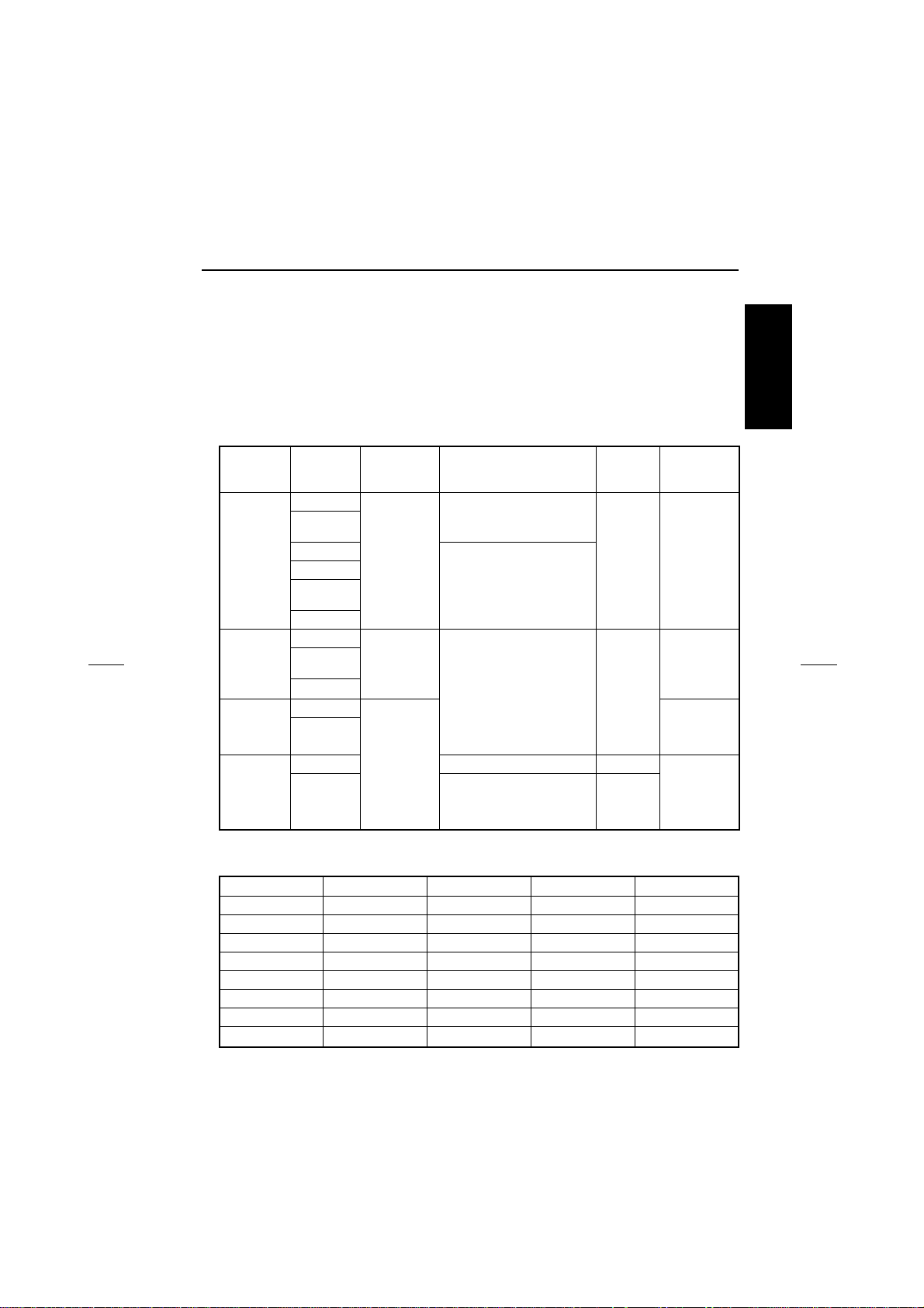
Maximum loadage
Mode Paper type Weight
Non-sort Plain paper
Recycled
paper
Thick paper
OHP
Blueprint
master
Postcard
Non-sort/
Sort/Group
Staple Plain paper
Punch Plain paper 250 sheets 1st tray —
Plain paper
Recycled
paper
Thick paper
Recycled
paper
Recycled
paper
50 to 130g/m
13 ~ 34lbs
50 to 130g/m
13 ~ 34lbs
60 to 90g/m
16 to 24lbs
* Limited only to the same size
2
250 sheets
20 sheets
2
3000 sheets: Smaller than
A4R, 8.5 x 11R
1500 sheets: Larger than B4,
8.5 x 14
2
3000 sheets: Smaller than
A4R, 8.5 x 11R
1500 sheets: Larger than B4,
8.5 x 14
(80g/m
2
or 20lbs)
Paper exit
tray
1st tray —
Elevator
tray
Elevator
tray
No. of sheets
to be stapled
50 sheets
(80g/m2 or
20lbs)
For metric area
Non-sort Sort/Group Staple Punch (4 holes)
A3 !!!!
B4 !!!!
F4 !!!
A4R !!!
A4 !!!!
B5R !!!
B5 !!!!
A5R !
—
1-1
FS-113 PRODUCT SPECIFICATIONS
For inch area
11 x 17 !!!!!
8.5 x 14 !!!!
8.5 x 11R !!!!
I OUTLINE
8.5 x 11 !!!!!
5.5 x 8.5R !
5.5 x 8.5 !
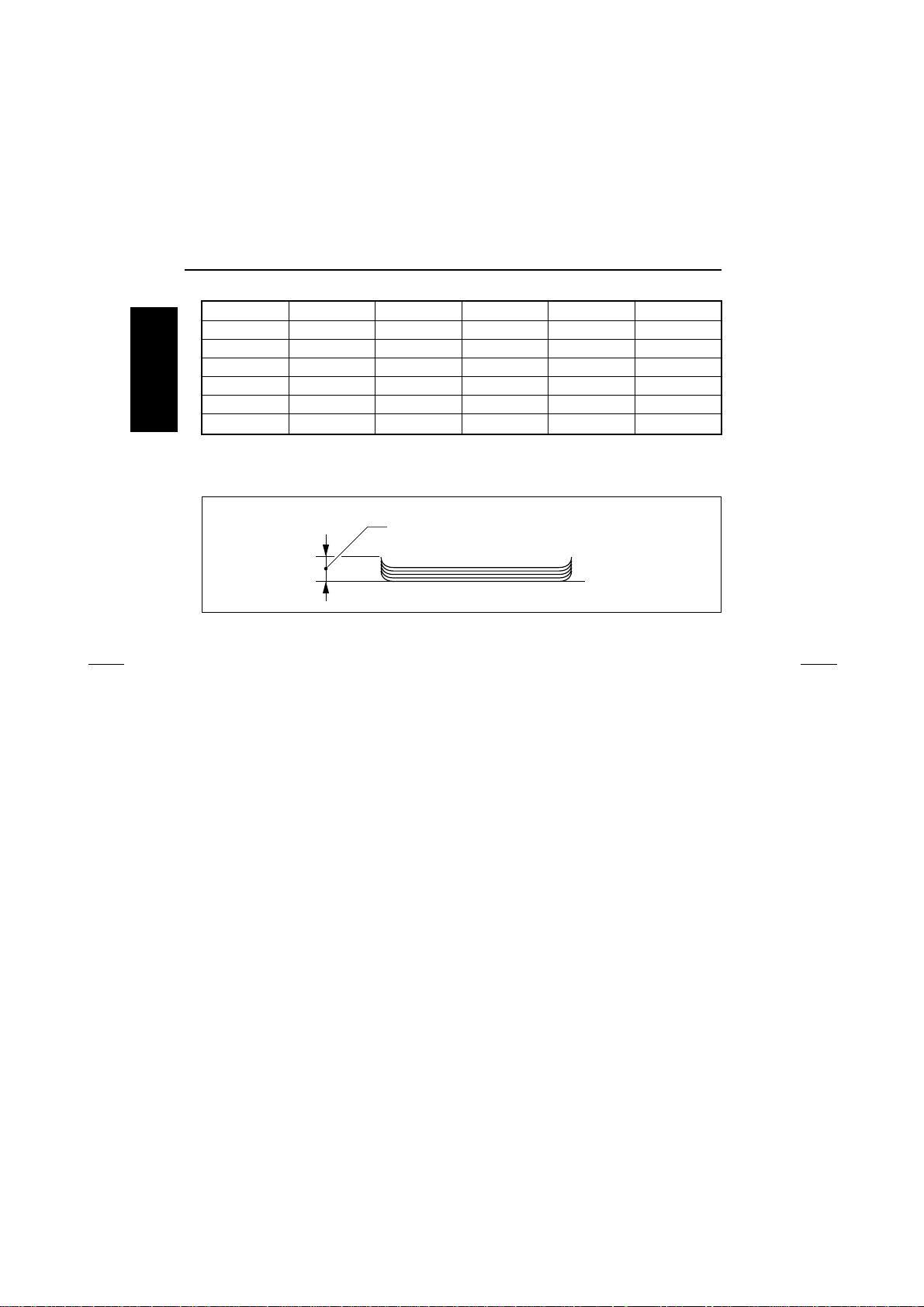
Amount of curling in paper (5 sheets):h= 10mm or less
Amount of sort offsetting (during sorting/grouping):
No. of sheets to be stapled: 50 sheets, max.
No. of staples contained in cartridge: 5000 staples/cartridge
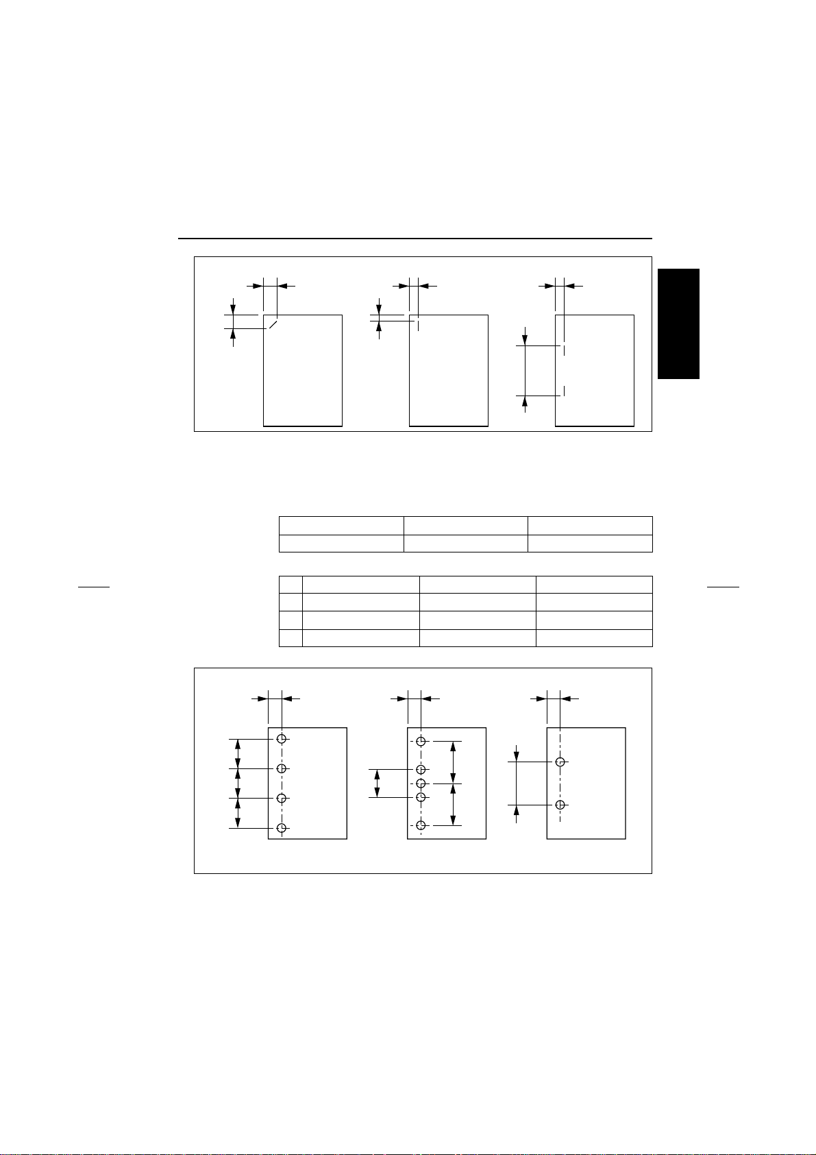
Stapling position: A = 12.1 ± 4mm (when the paper width is 297mm), 45°
Non-sort Sort/Group Staple Punch (2 holes) Punch (3 holes)
h
30mm
2
(80g/m
or 20lbs high quality paper with thickness less
than 5mm)
6.0 ± 4mm (when the paper width is 279mm), 28°
B = 12.1 ± 4mm (when the paper width is 297mm), 45°
16.2 ± 4mm (when the paper width is 279mm), 28°
C = 6.0 ± 4mm (when the paper width is 182 to 216mm)
D = 6.5 ± 4mm (when the paper width is 182 to 216mm)
E = 6.0 ± 4mm
F = 158.0 ± 4mm
1-2
FS-113 PRODUCT SPECIFICATIONS
A
B
D
C
E
F
Number of holes (For metric area): 4 holes
Number of holes (For inch area): 2 holes and 3 holes (Automatic switchover)
Number of holes (For Japan): 2 holes
Hole diameter 4 holes 2 holes and 3 holes 2 holes
φ 6 ± 0.5mm φ 8 ± 0.5mm φ 7 ± 0.5mm
Hole position 4 holes 2 holes and 3 holes 2 holes
A 11 ± 3mm 9.5 ± 3mm 13 ± 3mm
B 80 ± 1mm 70 ± 1mm 80 ± 1mm
C — 108 ± 1mm —
I OUTLINE
A
B
B
B
B
4 holes 2 holes and 3 holes 2 holes
A
C
B
C
1-3
A

FS-113 PRODUCT SPECIFICATIONS
C. Machine data
Power source: 24VDC ± 10% (supplied from the main body through RU-
Power consumption: M axim um 63VA
I OUTLINE
Weight: Approx. 39.2kg
Dimensions: 538mm (W) x 978.6mm (D) x 637mm (H)
D. Maintenance and life
Maintenance: Same as the main body
Machine service life: Same as the main body
E. Operating environment
Temperature: 10°C to 30°C (50°F to 86°F)
Humidity: 10% RH to 80% RH
Note:
• The information herein may be subject to change for improvement without notice.
101)
5VDC ± 10% (generated inside the FNS)
1-4
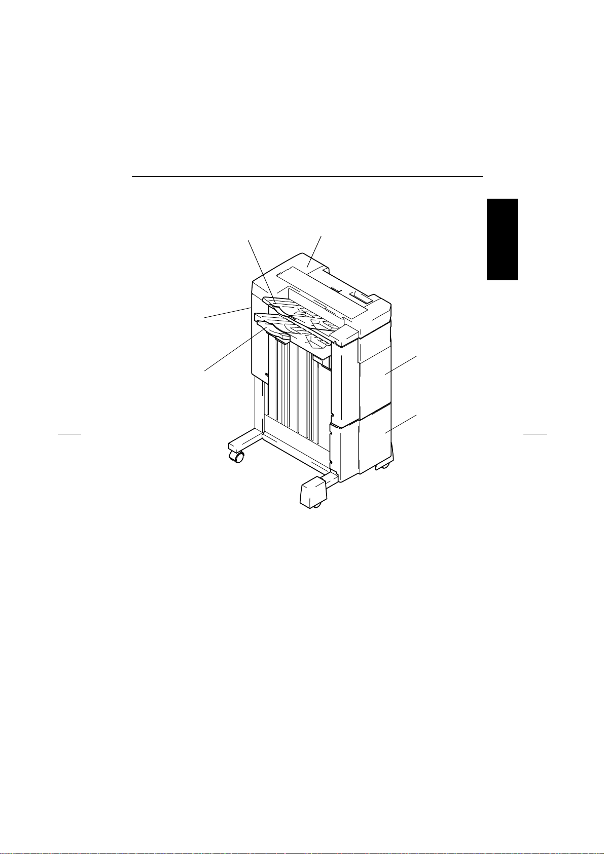
2. PARTS IDENTIFICATION
PARTS IDENTIFIC AT I O N
1
2
I OUTLINE
6
3
5
4
4643M001AA
1. 1st Tray
2. Upper Cover
3. Upper Front Cover
4. Lower Front Cover
5. Elevator Tray
6. Rear Cover
1-5
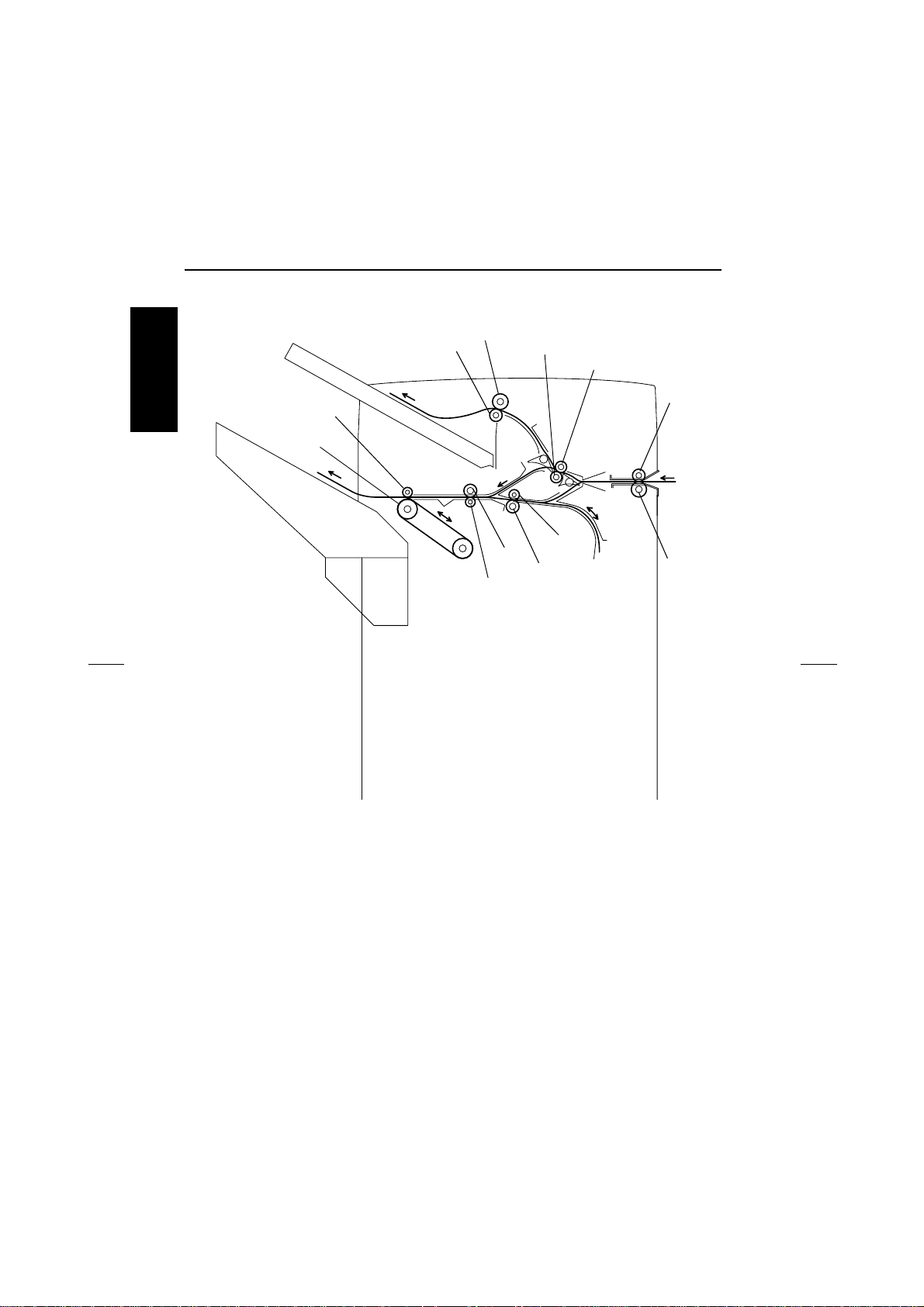
CROSS-SECTIONAL VIEW
3. CROSS-SECTIONAL VIEW
2
1
3
4
I OUTLINE
12
11
1. 1st Tray Exit Roll
2. 1st Tray Exit Roller
3. Upper Path Transport Roller
4. Upper Path Transport Roll
5. Entrance Roller
6. Entrance Roll
7
9
8
10
4643M002AA
7. Lower Path Transport Roll
8. Lower Path Transport Roller
9. Storage Roller
10. Storage Roll
11. Exit Roller
12. Exit Roll
5
6
1-6
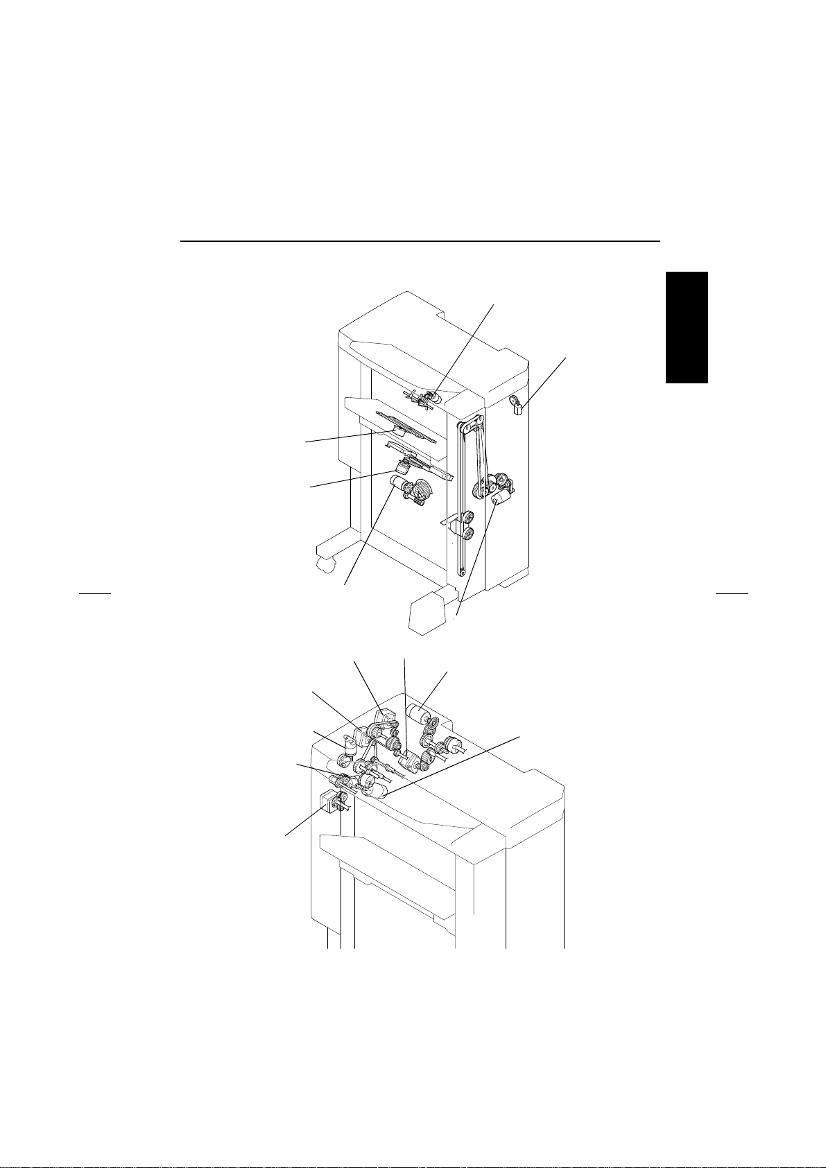
4. DRIVE SYSTEM
CD Aligning
Motor (M5)
Stapling Unit
Moving Motor (M6)
Lower Paddle Motor (M9)
Hole Position
Selector Motor (M14):
U.S.A. and Canada
DRIVE SYSTEM
I OUTLINE
Shift Motor (M8)
Upper Entrance Motor (M4)
Lower Entrance Motor (M2)
Exit Roller/Rolls
Spacing Motor (M13)
Upper Paddle
Motor (M15)
Exit Motor (M3)
4643M003AC
Elevator Motor (M7)
Entrance Motor (M1)
Punch Motor (M11)
Storage Roller/Rolls
Spacing Motor (M12)
4643M004AA
1-7
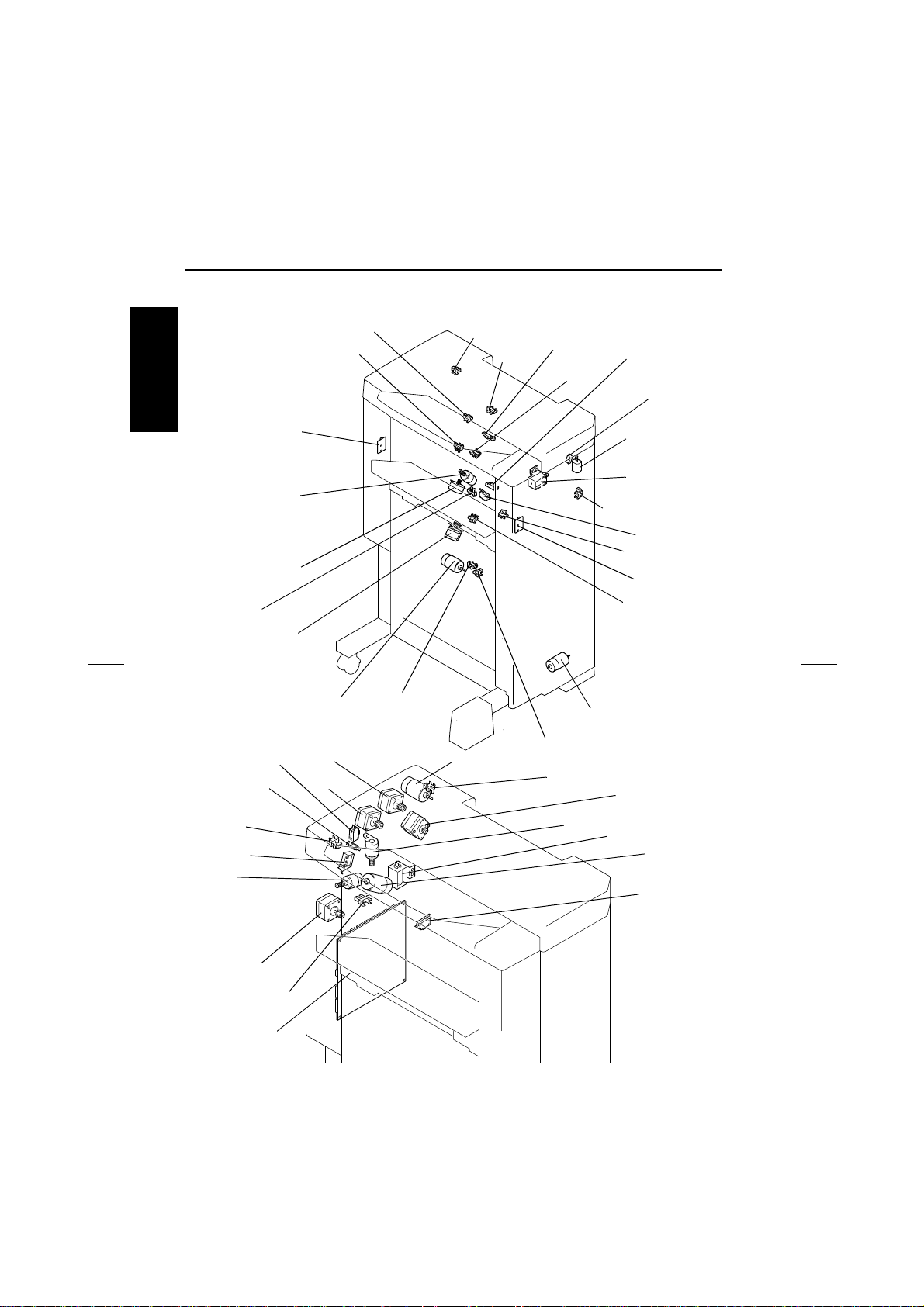
ELECTRICAL COM PONENTS LAYOUT
5. ELECTRICAL COMPONENTS LAYOUT
I OUTLINE
PC8
PC13
PWB-D
M9
M5
M6
S3
M4
M2
M8
PC4
PC6
PC11
M11
PC18
PC1
PC2
PC10
PC15
PC3
PC5
S4:U.S.A. and
Canada
M14:U.S.A. and
Canada
SL2
PC17
S2
PC9
PWB-C
PC14
M7
4643M005AC
M1
PC7
M15
SL3
M3
PWB-A
PC12
1-8
M13
SL1
M12
S1
4643M006AA
ELECTRICAL CO MPONENTS LAYO UT
Symbol Name Symbol Name
PWB-A Control Board PC1 1st Tray Exit Sensor
PWB-C Elevator Tray Upper Limit Sensor
LED
PC2 Lower Entrance Sensor
PC3 Storage Sensor
PWB-D Elevator Tray Upper Limit Sensor PQPC4 Upper Entrance Sensor
PC5 Finisher Tray Paper Detecting Sen-
sorM1 Entrance Motor
M2 Lower Entrance Motor PC6 1st Tray Full Detecting Sensor
M3 Exit Motor PC7 Elevator Tray Full Detecting Sensor
M4
M5
Upper Entrance Motor
CD Aligning Motor
PC8 Elevator Tray Paper Detecting Sen-
sor
M6 Stapling Unit Moving Motor PC9 CD Aligning Home Position Sensor
M7 Elevator Motor PC10 Shift Home Position Sensor
M8 Shift Motor PC11 Shift Motor Pulse Sensor
M9
M11
Lower Paddle Motor
Punch Motor
PC12 Storage Roller Home Position Sen-
sor
M12 Storage Roller/Rolls Spacing Motor PC13 Exit Roller Home Position Sensor
M13 Exit Roller/Rolls Spacing Motor PC 14 Staple Home Position Sensor
M14 Hole Position Selector Motor PC15 Punch Motor Pulse Sensor
M15 Upper Paddle Motor PC17 Front Door Detecting Sensor
SL1 Upper/Lower Entrance Switching
Solenoid
SL2 1st Tray Entrance Selecting Sole-
noid
PC18 Upper Cover Detecting Sensor
S1 Set Switch
S2 Elevator Tray Upper Limit Switch
S3 Elevator Tray Lower Limit Switch
SL3 Upper Paddle Solenoid S4 Hole Punch Position Switch
I OUTLINE
1-9

ELECTRICAL COM PONENTS LAYOUT
I OUTLINE
Blank page
1-10
PAPER TRANSPO RT
II UNIT EXPLANATION
1. PAPER TRANSPORT
1.1 Paper Transport Mechanism
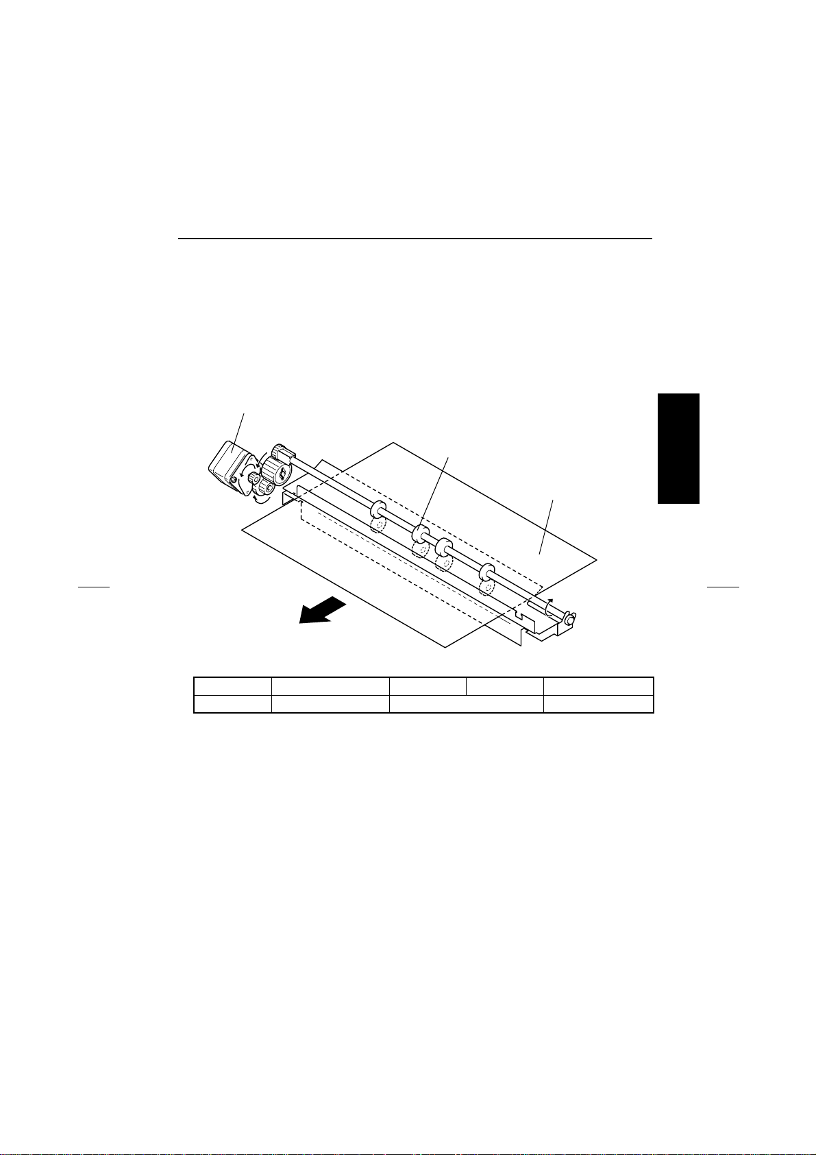
(1) Entrance Section Paper Transport Mechanism
• The Entrance Roller is turned to transport the paper into the Finisher as the Entrance Motor
is energized.
Entrance Motor (M1)
Entrance Roller
Paper
4643M007AD
CONTROL SIGNAL Energized Deenergized WIRING DIAGRAM
M1 PWB-A PJ9A-1~-4 Pulse output 3-B
II UNIT EXPLANATION
2-1
PAPER TRANSPO RT
(2) 1st Tray Paper Transport Mechanism
• Paper transport to the 1st Tray takes place when the Finisher is in the Non-Sort mode.
• The Upper Path Transport Roller and 1st Tray Exit Roller turn to transport the paper into the
1st Tray as the motor is energized.
• The 1st Tray Entrance Selecting Solenoid and Upper/Lower Entrance Switching Solenoid are
energized to select the paper path into the 1st Tray.
II UNIT EXPLANATION
Upper Entrance Motor (M4)
Upper Path Transport Roller
Paper
1st Tray Exit Roller
SL2
4643M008AB
SL1
Upper/Lower Entrance
Switching Solenoid (SL1)
1st Tray Entrance Selecting Solenoid (SL2)
CONTROL SIGNAL Energized Deenergized WIRING DIAGRAM
M4 PWB-A PJ9A-5~-8 Pulse output 3-B
SL1 PWB- A PJ18A -2 L H
SL2 PWB- A PJ18A -4 L H
2-2
4643M011AE
7-E
PAPER TRANSPO RT
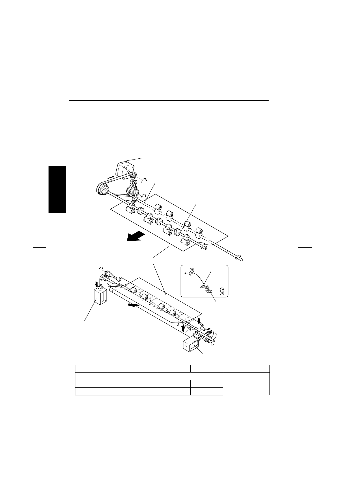
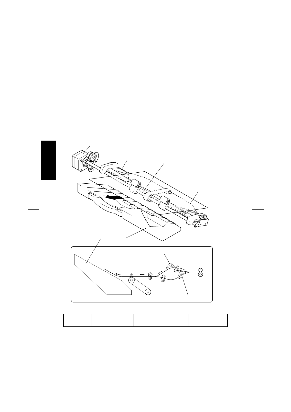
(3) Finisher Tray Paper Transport Mechanism
• Paper transport to the Finisher Tray takes place when the Finisher is in the Staple mode.
• As the Lower Entrance Motor is energized, the Storage Roller turns to transport the paper
toward the exit direction.
• By turning the Exit Motor backward, paper is transported onto the Finisher Tray.
• Either the upper paper path or lower paper path is used depending on the copy mode to
transport the paper onto the Finisher Tray.
• The upper paper path is selected when the Upper/Lower Entrance Switching Solenoid is
energized, while the 1st Tray Entrance Selecting Solenoid is deenergized.
• The lower paper path is selected when the Upper/Lower Entrance Switching Solenoid is
deenergized.
Lower Entrance Motor (M2)
Finisher Tray
Storage Roller
Lower Path Transport Roller
Paper
II UNIT EXPLANATION
Exit Motor (M3)
1st Tray Entrance Selecting Solenoid (SL2)
Upper/Lower Entrance Switching Solenoid (SL1)
4643M009AG
CONTROL SIGNAL Energiz ed Deenergized WIRING DIAGRAM
M2 PWB-A PJ9A-9~-12 Pulse output 3-A
2-3
PAPER TRANSPO RT
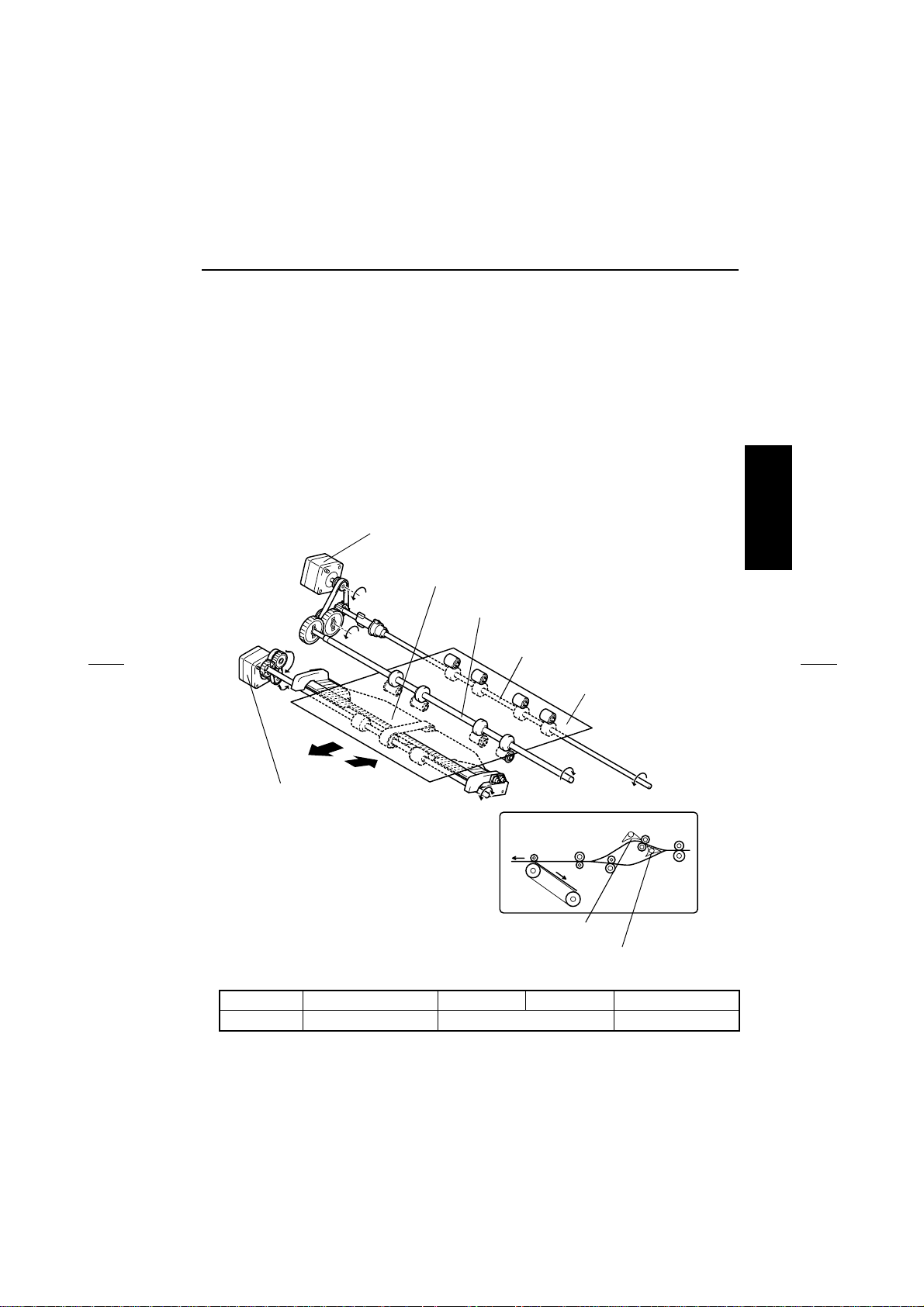
(4) Elevator Tray Paper Transport Mechanism
• As the motor is energized, the Exit Roller turns to transport the paper into the Elevator Tray.
• Either the upper paper path or lower paper path is used depending on the copy mode to
transport the paper into the Elevator Tray.
• The upper paper path is selected when the Upper/Lower Entrance Switching Solenoid is
energized, while the 1st Tray Entrance Selecting Solenoid is deenergized.
• The lower paper path is selected when the Upper/Lower Entrance Switching Solenoid is
deenergized.
II UNIT EXPLANATION
Exit Motor (M3)
Finisher Tray
Exit Roller
Paper
Elevator Tray
4643M010AF
1st Tray Entrance Selecting Solenoid (SL2)
Upper/Lower Entrance Switching Solenoid (SL1)
4643M012AD
CONTROL SIGNAL E nergized Deenergized W IR ING DIAG RAM
M3 PWB-A PJ8A-1~-4 Pulse output 2-A
2-4
PAPER TRANSPO RT
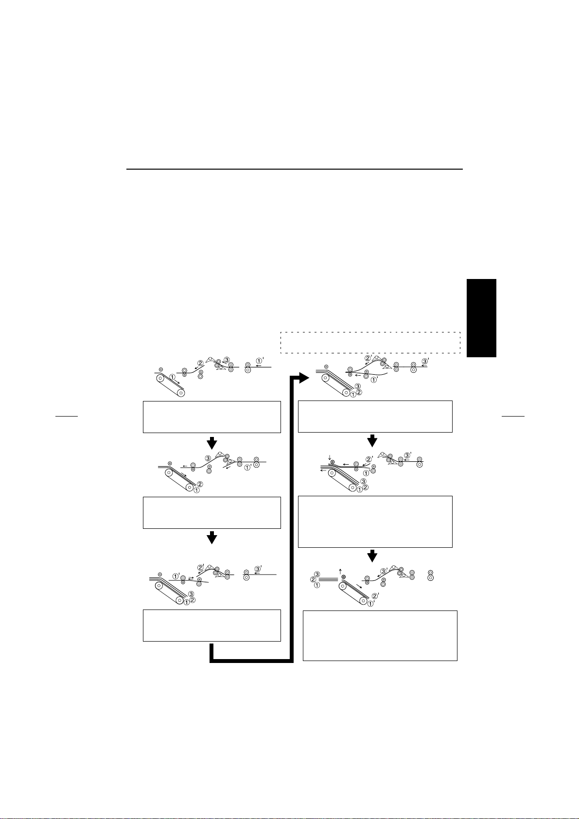
1.2 Paper Switchback Mechanism
• When the last paper of the 1st copy set is transported onto the Finisher Tray during a multicopy cycle in the Sort Staple mode, the 1st paper of the subsequent copy sets, which is to be
next transported, undergoes a switchback sequence. The paper for the switchback is transported via the lower paper path.
• The 2nd paper of the 2nd copy set is placed over the paper which has undergone the switchback sequence. After the 1st copy set has been fed into the Elevator Tray, the 1st and 2nd
sheets of paper of the 2nd copy set are together transported onto the Finisher Tray.
• The switchback sequence of the paper is performed by turning the motor backward, which
turns the Lower Path Transport Roller and Storage Roller backward.
• The sheet of paper to be transported next to the one subjected to the switchback sequence is
transported via the upper paper path.
<3 A4R originals for 2 copy sets>
➀, ➁, ➂
➀
: Sheets of paper for the 1st copy set
’, ➁’, ➂’: Sheets of paper for the 2nd copy set
II UNIT EXPLANATION
4643M027AD
The sheets of paper for the 1st copy
are transported via the upper paper
path onto the Finisher Tray.
4643M031AH
The 1st sheet of paper of the 2nd copy
set is transported via the lower paper
path.
4643M028AG
The 1st sheet of paper of the 2nd copy
set undergoes the switchback
sequence.
4643M029AG
The 1st and 2nd sheets of paper of the 2nd
copy set are transported together, one on
top of the other.
4643M030AH
The Exit Rolls are pressed against the Exit
Roller to feed the sheets of paper of the 1st
copy set out. At the same time, the 1st and
2nd sheets of paper of the 2nd copy set are
transported toward the exit.
4643M032AE
When the 1st copy set is fed out, the Exit
Roller starts turning backward to transport
the 1st and 2nd sheets of paper of the 2nd
copy set to the Finisher Tray . The Exit Rolls
leave the Exit Roller.
2-5
PAPER TRANSPO RT
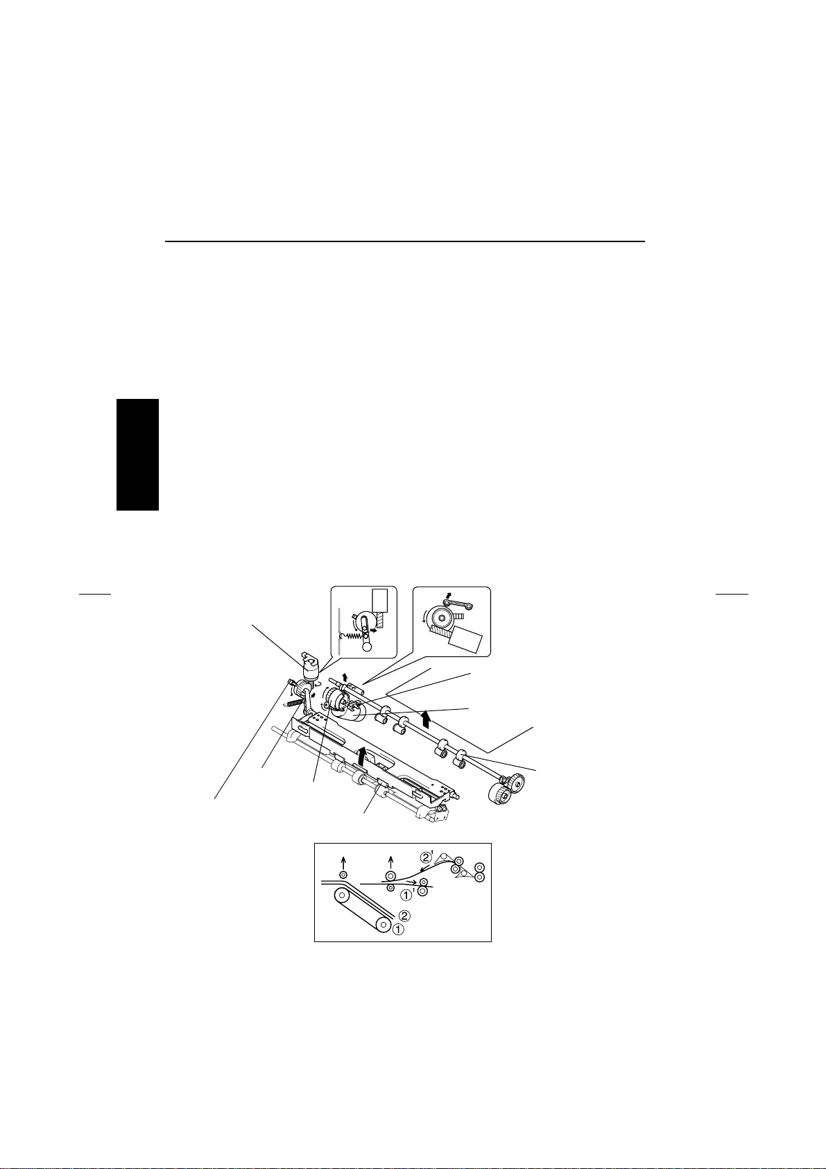
1.3 Roller/Rolls Spacing Mechanism
(1) Storage Roller/Rolls Spacing Mechanism
• While in continuous copying in the Sort Staple mode, the Storage Roller stops once when the
switchback of the 1st paper after the 2nd copy is completed. However, when the paper size is
larger than 217mm, the 2nd paper reaches the Storage Roller. So, the Storage Roller is
raised up to be separated from the Storage Roll.
• After the 2nd paper stops, the Storage Roller goes down and convey 2 sheets that are put
one over another onto the process tray.
• The separation of the Storage Roller is made by rotating the cam through the drive of the
motor and moving the lever to right and left.
(2) Exit Roller/Rolls Spacing Mechanism
• Paper needs to be temporarily transported to the Finisher Tray in the Staple mode, which
II UNIT EXPLANATION
makes it necessary to raise the Exit Rolls to provide a given clearance from the Exit Roller.
• After the stapling sequence has been completed, the Exit Rolls are lowered and pressed
against the Exit Roller so that the paper can be fed out.
• The Exit Rolls are spaced from the Exit Roller as a lever is moved to the right and left by the
corresponding motor.
Exit Roller/Rolls
Spacing Motor (M13)
Lever
Exit Rolls Home Position
Sensor (PC13)
Cam
Exit Rolls
Storage Roller Home
Position Sensor (PC12)
Storage Roller/Rolls
Spacing Motor (M12)
Storage Roller
4643M013AE
4643M033AD
2-6

PAPER TRANSPO RT
CONTROL SIGNAL Energized Deenergized WIRING DIAGRAM
M12 PWB-A PJ8A-6 Pulse outpu t L 2-A
M13 PWB-A PJ16A-2 H L 7-D
II UNIT EXPLANATION
2-7
 Loading...