

Page 1

SERVICE MANUAL
MODEL
FS-112
Finisher Unit
NOVEMBER 2002
CSM-FS112
Page 2

Page 3

FS-112
SERVICE MANUAL
Used On Model 7145
November 2002
Page 4

IMPORTANT NOTICE
Because of the possible hazards to an inexperienced
person servicing this equipment, as well as the risk of
damage to the equipment, Konica Business Technologies strongly recommends that all servicing be
performed by Konica-trained service technicians only.
Changes may have been made to this equipment to
improve its performance after this service manual was
printed. Accordingly, Konica Business Technologies,
Inc., makes no representations or warranties, either
expressed or implied, that the information contained
in this service manual is complete or accurate. It is
understood that the user of this manual must assume
all risks or personal injury and/or damage to the
equipment while servicing the equipment for which
this service manual is intended.
Corporate Publishing Department
© 2002, KONICA BUSINESS TECHNOLOGIES, INC.
All rights reserved.
Printed in U.S.A.
Page 5

CONTENTS
CONTENTS
SAFETY AND IMPORTANT WARNING ITEMS
Refer to the 7145 service manual on page . . . . . . . . . . . . . . . . . . . . . . . . . . . . . . . . . . . . . . . . . . . . . . . . S-1
I OUTLINE
1. FS-112 PRODUCT SPECIFICATIONS . . . . . . . . . . . . . . . . . . . . . . . . . . . . . . . . . . . . . . . . . . . . . . . . 1-1
2. CENTER CROSS-SECTIONAL DIAGRAM . . . . . . . . . . . . . . . . . . . . . . . . . . . . . . . . . . . . . . . . . . . . . 1-5
3. DRIVE SYSTEM DIAGRAM . . . . . . . . . . . . . . . . . . . . . . . . . . . . . . . . . . . . . . . . . . . . . . . . . . . . . . . . . 1-6
3.1 Conveyance/Paper exit section. . . . . . . . . . . . . . . . . . . . . . . . . . . . . . . . . . . . . . . . . . . . . . . . . . . 1-6
3.2 Alignment section . . . . . . . . . . . . . . . . . . . . . . . . . . . . . . . . . . . . . . . . . . . . . . . . . . . . . . . . . . . . . 1-7
3.3 Stapler section. . . . . . . . . . . . . . . . . . . . . . . . . . . . . . . . . . . . . . . . . . . . . . . . . . . . . . . . . . . . . . . . 1-7
3.4 Tray section. . . . . . . . . . . . . . . . . . . . . . . . . . . . . . . . . . . . . . . . . . . . . . . . . . . . . . . . . . . . . . . . . . 1-8
II UNIT EXPLANATION
1. CONVEYANCE SECTION . . . . . . . . . . . . . . . . . . . . . . . . . . . . . . . . . . . . . . . . . . . . . . . . . . . . . . . . . . 2-1
1.1 Composition. . . . . . . . . . . . . . . . . . . . . . . . . . . . . . . . . . . . . . . . . . . . . . . . . . . . . . . . . . . . . . . . . . 2-1
1.2 Operation. . . . . . . . . . . . . . . . . . . . . . . . . . . . . . . . . . . . . . . . . . . . . . . . . . . . . . . . . . . . . . . . . . . . 2-2
1.2.1 Conveyance control . . . . . . . . . . . . . . . . . . . . . . . . . . . . . . . . . . . . . . . . . . . . . . . . . . . . . . . 2-2
2. PAPER EXIT SECTION . . . . . . . . . . . . . . . . . . . . . . . . . . . . . . . . . . . . . . . . . . . . . . . . . . . . . . . . . . . . 2-3
2.1 Composition. . . . . . . . . . . . . . . . . . . . . . . . . . . . . . . . . . . . . . . . . . . . . . . . . . . . . . . . . . . . . . . . . . 2-3
2.2 Operation. . . . . . . . . . . . . . . . . . . . . . . . . . . . . . . . . . . . . . . . . . . . . . . . . . . . . . . . . . . . . . . . . . . . 2-4
2.2.1 Paper exit control . . . . . . . . . . . . . . . . . . . . . . . . . . . . . . . . . . . . . . . . . . . . . . . . . . . . . . . . . 2-4
2.2.2 Paper stack control . . . . . . . . . . . . . . . . . . . . . . . . . . . . . . . . . . . . . . . . . . . . . . . . . . . . . . . 2-5
2.2.3 Shutter control . . . . . . . . . . . . . . . . . . . . . . . . . . . . . . . . . . . . . . . . . . . . . . . . . . . . . . . . . . . 2-6
3. ALIGNMENT SECTION . . . . . . . . . . . . . . . . . . . . . . . . . . . . . . . . . . . . . . . . . . . . . . . . . . . . . . . . . . . . 2-7
3.1 Composition. . . . . . . . . . . . . . . . . . . . . . . . . . . . . . . . . . . . . . . . . . . . . . . . . . . . . . . . . . . . . . . . . . 2-7
3.2 Operation. . . . . . . . . . . . . . . . . . . . . . . . . . . . . . . . . . . . . . . . . . . . . . . . . . . . . . . . . . . . . . . . . . . . 2-8
3.2.1 Paper alignment control . . . . . . . . . . . . . . . . . . . . . . . . . . . . . . . . . . . . . . . . . . . . . . . . . . . . 2-8
4. STAPLER SECTION . . . . . . . . . . . . . . . . . . . . . . . . . . . . . . . . . . . . . . . . . . . . . . . . . . . . . . . . . . . . . 2-12
4.1 Composition. . . . . . . . . . . . . . . . . . . . . . . . . . . . . . . . . . . . . . . . . . . . . . . . . . . . . . . . . . . . . . . . . 2-12
4.2 Operation. . . . . . . . . . . . . . . . . . . . . . . . . . . . . . . . . . . . . . . . . . . . . . . . . . . . . . . . . . . . . . . . . . . 2-13
4.2.1 Stapler control . . . . . . . . . . . . . . . . . . . . . . . . . . . . . . . . . . . . . . . . . . . . . . . . . . . . . . . . . . 2-13
4.2.2 Staple control . . . . . . . . . . . . . . . . . . . . . . . . . . . . . . . . . . . . . . . . . . . . . . . . . . . . . . . . . . . 2-14
5. TRAY SECTION . . . . . . . . . . . . . . . . . . . . . . . . . . . . . . . . . . . . . . . . . . . . . . . . . . . . . . . . . . . . . . . . . 2-15
5.1 Composition. . . . . . . . . . . . . . . . . . . . . . . . . . . . . . . . . . . . . . . . . . . . . . . . . . . . . . . . . . . . . . . . . 2-15
5.2 Operation. . . . . . . . . . . . . . . . . . . . . . . . . . . . . . . . . . . . . . . . . . . . . . . . . . . . . . . . . . . . . . . . . . . 2-16
5.2.1 Detection of the lower limit of the tray . . . . . . . . . . . . . . . . . . . . . . . . . . . . . . . . . . . . . . . . 2-16
5.2.2 Tray count . . . . . . . . . . . . . . . . . . . . . . . . . . . . . . . . . . . . . . . . . . . . . . . . . . . . . . . . . . . . . 2-16
5.2.3 Tray up/down control while in print operation. . . . . . . . . . . . . . . . . . . . . . . . . . . . . . . . . . . 2-16
I OUTLINEII UNIT EXPLANATIONIII DIS./ASSEMBLY
III DISASSEMBLY/ASSEMBLY
1. EXTERNAL SECTION . . . . . . . . . . . . . . . . . . . . . . . . . . . . . . . . . . . . . . . . . . . . . . . . . . . . . . . . . . . . . 3-1
1.1 Removing and reinstalling of the FNS. . . . . . . . . . . . . . . . . . . . . . . . . . . . . . . . . . . . . . . . . . . . . . 3-1
2. STAPLER SECTION . . . . . . . . . . . . . . . . . . . . . . . . . . . . . . . . . . . . . . . . . . . . . . . . . . . . . . . . . . . . . . 3-2
iii
Page 6

CONTENTS
3. PAPER EXIT SECTION . . . . . . . . . . . . . . . . . . . . . . . . . . . . . . . . . . . . . . . . . . . . . . . . . . . . . . . . . . . . 3-4
I OUTLINE
II UNIT EXPLANATION
2.1 Removing and reinstalling of the stapler unit. . . . . . . . . . . . . . . . . . . . . . . . . . . . . . . . . . . . . . . . . 3-2
2.2 Replacing the stapler cartridge . . . . . . . . . . . . . . . . . . . . . . . . . . . . . . . . . . . . . . . . . . . . . . . . . . . 3-3
3.1 Removing and reinstalling of the paper exit roller /A . . . . . . . . . . . . . . . . . . . . . . . . . . . . . . . . . . . 3-4
3.2 Removing and reinstalling of the tray. . . . . . . . . . . . . . . . . . . . . . . . . . . . . . . . . . . . . . . . . . . . . . . 3-6
3.3 Removing and reinstalling of the up/down wire . . . . . . . . . . . . . . . . . . . . . . . . . . . . . . . . . . . . . . . 3-8
III DIS./ASSEMBLY
iv
Page 7
I OUTLINE
1. FS-112 PRODUCT SPECIFICATIONS
FS-112 PRODUCT SPECIFICATIONS
A. Type
Type: Built-in type compact finisher (multiple trays type)
Option: Finisher tray [FT-107] Up to two trays can be installed (up to 4
trays in total together with the standard trays)
B. Functions
Applicable copy paper: Same as the main body
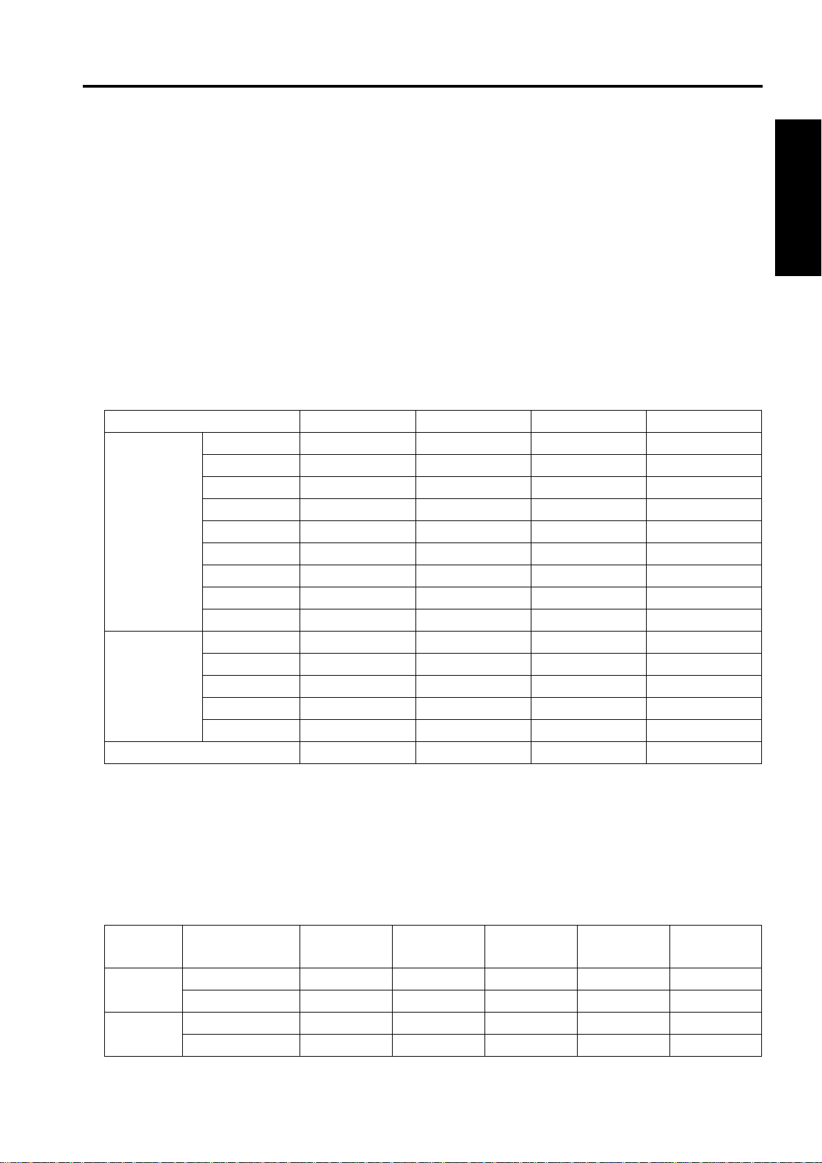
Paper size:
Non-sort Sort/group 1 staple 2 staples
Metric series A3 !!!!
B4 !!!!
F4 !!!!
A4R !!!!
A4 !!!!
B5R !!!!
B5 !!!!
A5R !!!
B6R*1 !
Inch series 11 x 17 !!!!
8.5 x 14 !!!!
8.5 x 11R !!!!
8.5 x 11 !!!!
5.5 x 8.5R !!!!
Non-standard size !
I OUTLINE
*1 Only for metric area
Maximum paper capacity: 2 trays: 100 + 1000 = 1100 sheets
3 trays: 100 + 100 + 600 = 800 sheets
4 trays: 100 x 4 = 400 sheets
Stack capacity (80g/m
• 2-trays specification (standard)
Tray 1 Non-staple 100 sheets 100 sheets 100 sheets 10 sheets 10 sheets
Staple 10 sets 10 sets 10 sets — —
Tray 2 Non-staple — 1000 sheets 300 sheets 50 sheets —
Staple — 50 sets 20 sets — —
2
or 20lbs high-quality paper)
Small size Medium size Large size Special paper Non-standard
paper
1-1
Page 8
FS-112 PRODUCT SPECIFICATIONS
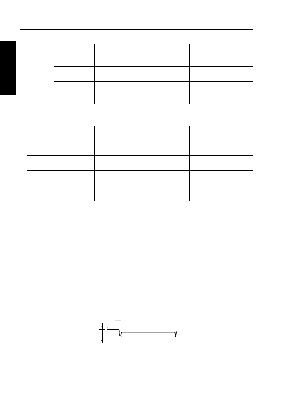
• 3-trays specification
Tray 1 Non-staple 100 sheets 100 sheets 100 sheets 10 sheets 10 sheets
Staple 10 sets 10 sets 10 sets — —
I OUTLINE
Tray 2 Non-staple — 100 sheets 100 sheets 10 sheets —
Staple — 10 sets 10 sets — —
Tray 3 Non-staple — 600 sheets 200 sheets 50 sheets —
Staple — 30 sets 15 sets — —
• 4-trays specification
Tray 1 Non-staple 100 sheets 100 sheets 100 sheets 10 sheets 10 sheets
Staple 10 sets 10 sets 10 sets — —
Tray 2 Non-staple — 100 sheets 100 sheets 10 sheets —
Staple — 10 sets 10 sets — —
Tray 3 Non-staple — 100 sheets 100 sheets 10 sheets —
Staple — 10 sets 10 sets — —
Tray 4 Non-staple — 100 sheets 100 sheets 10 sheets —
Staple — 10 sets 10 sets — —
Small size Medium size Large size Special paper Non-standard
paper
Small size Medium size Large size Special paper Non-standard
paper
Small size : B6R, A5R, 5.5 x 8.5R
Medium size : A4, A4R, B5, B5R, 8.5 x 11, 8.5 x 11R
Large size : A3, B4, F4, 11 x 17, 8.5 x 14
Special paper*1: Thin paper (Less than 60g/m
2
or 16lbs), thick paper (over 128g/m
or 32lbs), blueprint master, OHP, etc.
*1 S ort, stap le not all owe d
Note:
• The above figures apply to when papers of the same size are stacked continuously.
• The number of stacked s heets in staple mo de must no t exceed the stack sh eet capac ity for non -stap le
mode.
Paper curling (5 sheets) : h = 10mm or less
h
2
Amount of sort off-setting: 30mm
(during sorting/grouping) 20mm (A5R, 5.5 x 8.5R)
1-2
Page 9
FS-112 PRODUCT SPECIFICATIONS
C. Staple mode
Staple ability: Maximum 50 sheets ( with 80g/m2 or 20lbs paper, paper thic knes s
less than 5mm)
Staple capacity: 5,000 staples/cartridge
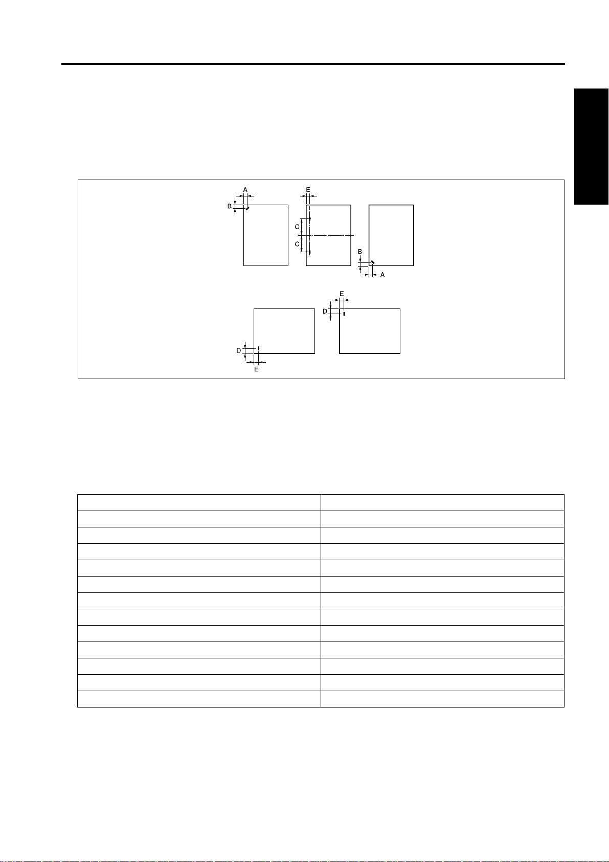
Staple position:
I OUTLINE
A = 8.6mm ± 3mm
B = 8.6mm ± 3mm
C = refer to following table
D = 10.5mm ± 3mm
E = 8.0mm ± 3mm
Paper Size C (mm)
A3/A4 60 ± 4
B4/B5 53 ± 4
A4R 90 ± 4
B5R 80 ± 4
A5R 63 ± 4
F4 (8 x 13) 90 ± 4
F4 (8.125 x 13, 8.125 x 13.25) 91.5 ± 4
F4 (8.25 x 13) 93 ± 4
F4 (8.5 x 13) 95 ± 4
11 x 17/8.5 x 11 52 ± 4
8.5 x 14/8.5 x 11R 95 ± 4
5.5 x 8.5R 60 ± 4
1-3
Page 10

FS-112 PRODUCT SPECIFICATIONS
D. Machine data
Power source: 24VDC/5V (supplied from the main body)
Power consumption : Maximum 70VA
Weight: Approx. 13kg
Dimensions: 707mm (W) x 507mm (D) x 392mm (H)
I OUTLINE
E. Maintenance and life
Maintenance: Same as the main body
Machine service life: Same as the main body
F. Operating environment
Temperature: 10°C to 30°C (50°F to 86°F)
Humidity: 10% RH% to 80% RH
Note:
• The information herein may be subject to change for improvement without notice.
1-4
Page 11
CENTER CROSS-SECTIONAL DIAGRAM
2. CENTER CROSS-SECTIONAL DIAGRAM
[6] [7] [8] [9]
[5]
[4]
[3]
[2]
I OUTLINE
[1]
[1] Stapler [6] Shutter
[2] Tray 2 [7] Alignment plate
[3] Optional tray 2 [8] Conveyance belt
[4] Optional tray 1 [9] Conveyance roller
[5] Tray 1
1-5
Page 12

DRIVE SYSTEM DIAGRAM
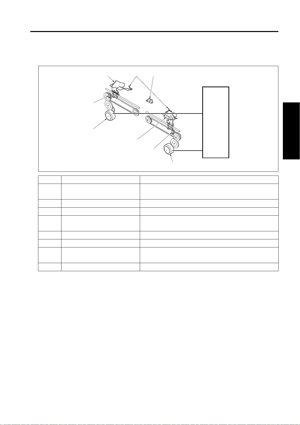
3. DRIVE SYSTEM DIAGRAM
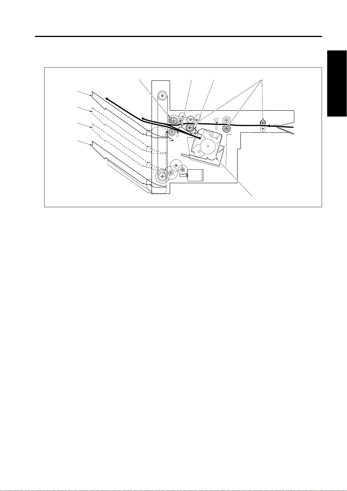
3.1 Conveyance/Paper exit section
I OUTLINE
[4]
[6]
[7]
[5]
[8]
[3]
[2]
[1] Paper jam release knob [5] M702 (Paper exit motor)
[2] Conveyance belt [6] M701 (Conveyance motor)
[3] Paper exit roller /A [7] Conveyance roller
[4] Clutch [8] Pressure roller
[1]
1-6
Page 13
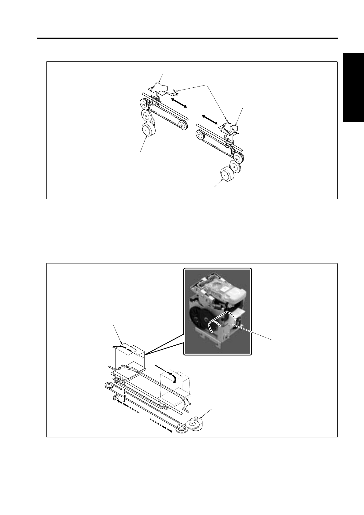
3.2 Alignment section
DRIVE SYSTEM DIAGRAM
[3]
[4]
[5]
[2]
[1]
[1] M704 (Alignment motor /F) [4] Rear stopper
[2] M703 (Alignment motor /R) [5] Alignment plate /F
[3] Alignment pla t e /R
3.3 Stapler section
I OUTLINE
[2]
[1]
[1] M705 (Stapler movement motor) [3] M708 (Stapler motor)
[2] Stapler
1-7
[3]
Page 14
DRIVE SYSTEM DIAGRAM
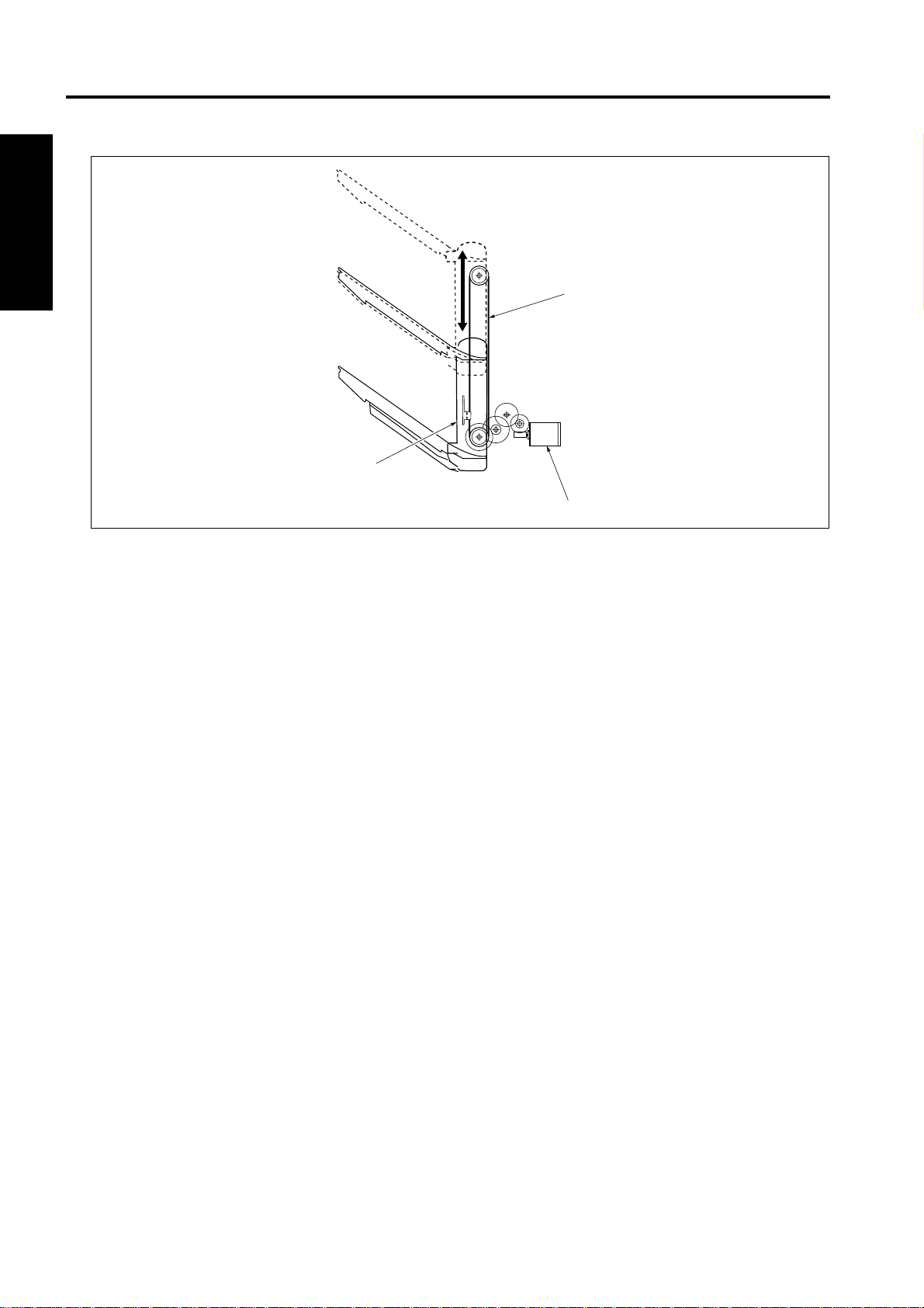
3.4 Tray section
I OUTLINE
[1]
[3]
[2]
[1] Up/down wire [3] Tray unit
[2] M706 (Tray up/down motor)
1-8
Page 15
II UNIT EXPLANATION
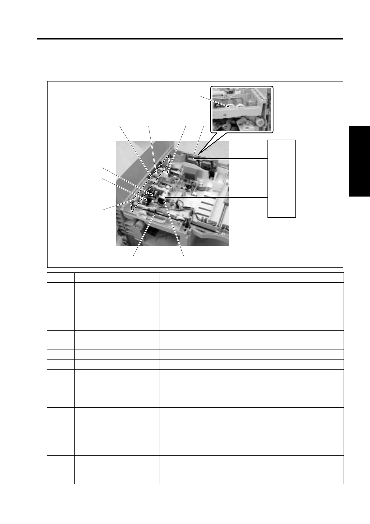
1. CONVEYANCE SECTION
1.1 Composition
CONVEYANCE SECTION
[4]
FS CB
M701
[2]
[3]
Symbol Name Function or method
[1]
[2] Conveyance pressure roller Transmission/transmission release of conveyance force of the
[3] Conveyance roller Paper conveyance
[4] PS702 (FNS entrance sensor) Detection of paper conveyed
M701 FNS conveyance motor Driving of the conveyance roller
SD701 (Roller release s olenoid)
Control of the pressure/release of the conveyance pressure
roller according to the line speed and paper size
While in operation, paper pressure by the conveyance pressure roller is released.
conveyance roller to the paper
Variable control speed method by 24VDC stepping motor
drive
[1]
II UNIT EXPLANATION
2-1
Page 16
CONVEYANCE SECTION
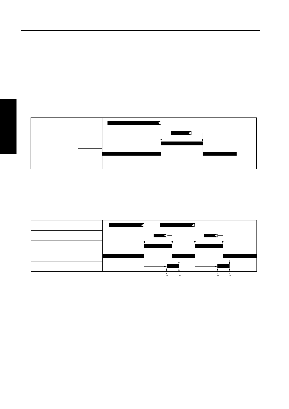
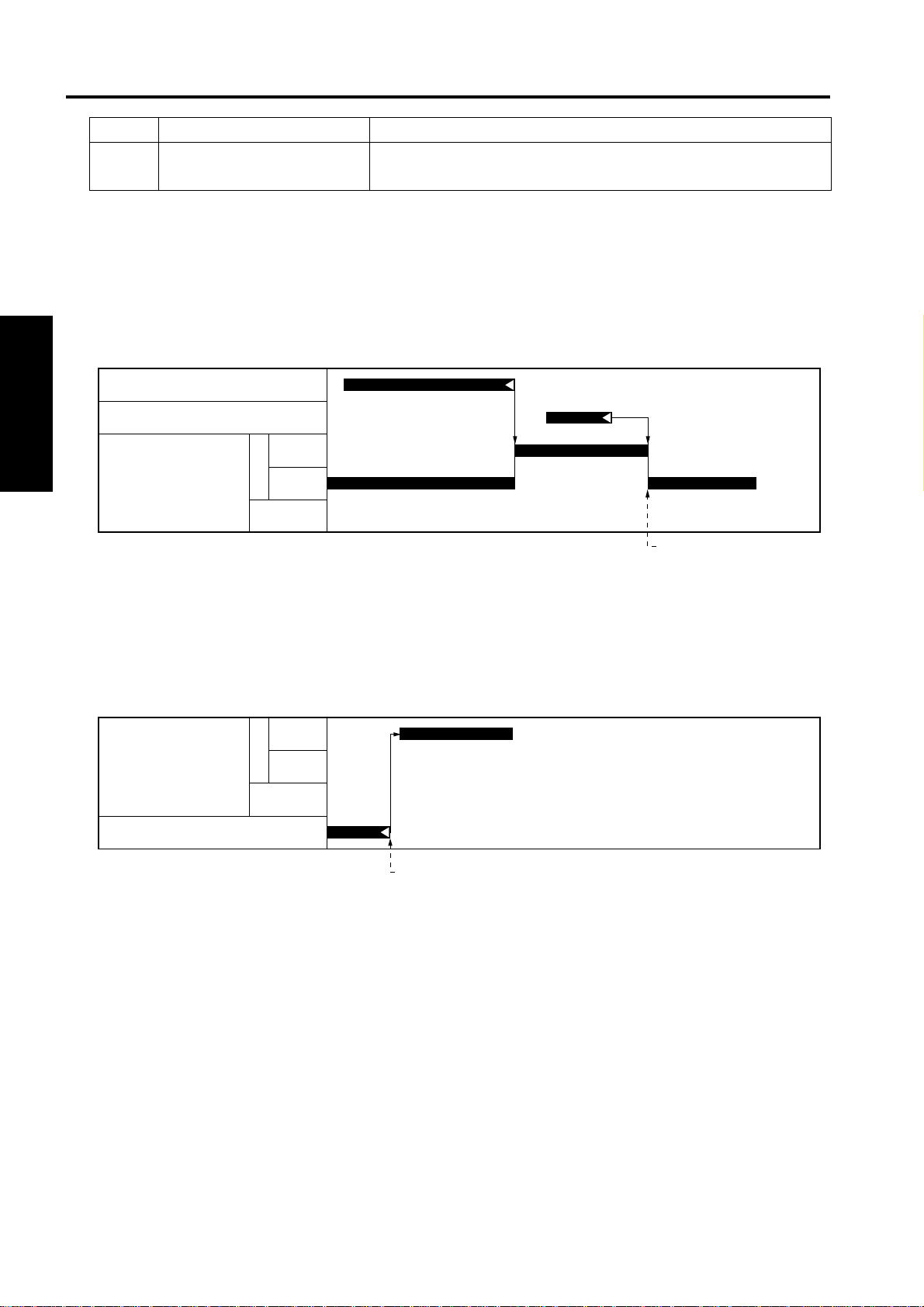
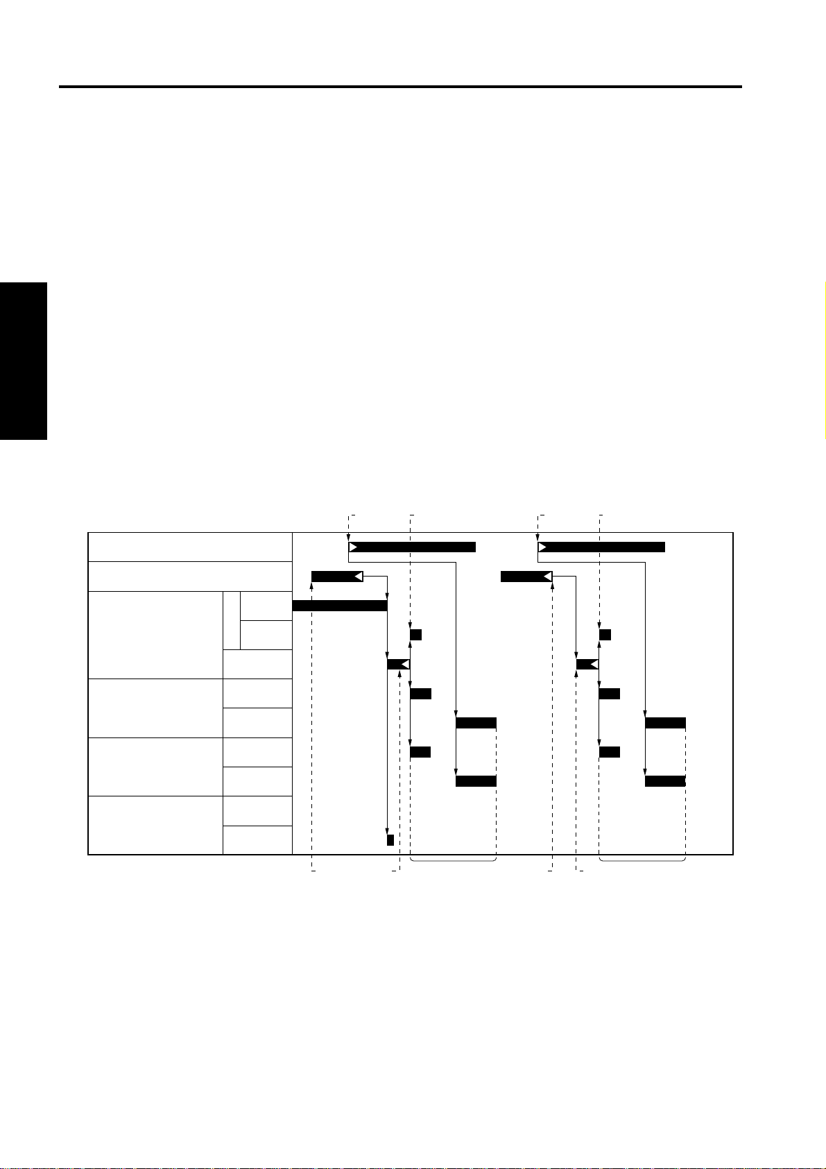
1.2 Operation
1.2.1 Conveyance control
Conveyance controls can be roughly divided into the following 2 patterns:
A. Pattern 1: Normal conveyance control
• While the paper is nipped to both t he main body’s fixing roller and the FNS conveyance roller, the
M701 (FNS conveyan ce motor) opera tes at the speed of 230 mm/s accor ding to the mai n body line
speed. When the paper passes through the fixing roller, the M701 operates at the speed of 600 mm/s.
PS2 (Main body’s fixing exit sensor)
PS702 (FNS entrance sensor)
II UNIT EXPLANATION
M701
(FNS conveyance motor)
SD701 (Roller release solenoid)
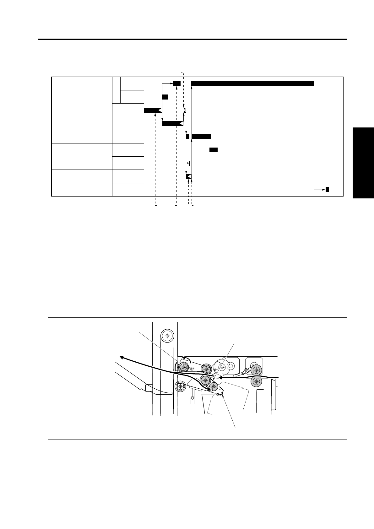
B. Pattern 2: Conveyance control of small-sized paper with paper intervals narrower
• While the paper is nipped to both t he main body’s fixing roller and the FNS conveyance roller, the
SD701 (Roller releas e solenoid) i s turned on to r elease the nip of the FNS conv eyance rolle r for the
increased productivity of sorting, grouping and stapling.
PS2 (Main body’s fixing exit sensor)
PS702 (FNS entrance sensor)
M701
(FNS conveyance motor)
SD701 (Roller release solenoid)
600mm/s
600 mm/s
230 mm/s
230mm/s
600mm/s
230mm/s
[2][1] [4][3]
[1] Release of the pressure roller for the 1st
paper
[2] Pressuring of the pressure roller for the 1st
paper
[3] Release of the pressure roller for the 2nd
paper
[4] Pressuring of the pressure roller for the
2nd paper
2-2
Page 17
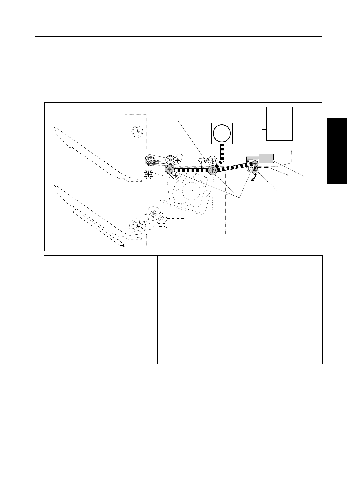
2. PAPER EXIT SECTION
2.1 Composition
[6] [7] [8] [9]
[5]
PAPER EXIT SECTION
[10]
[4]
[3]
[1][2]
Symbol Name Function or method
[1] M707 (Pressure motor) Driving of the pressure cam (when in forward rotation), Driving of
the shutter cam (when in backward rotation)
Driving of 24VDC DC brush motor
[2] MS702 (Shutter switch) Detection of abnormal release of the shutter while the tray is
going up and down
[3] Shutter cam Converting the rotational motion of the pressure motor into the
open/close motion of the shutter
[4] PS705 (Shutter sensor) HP detection of the shutter
[5] PS701 (Pressure sensor) Detection of pressure/release of the paper exit roller /A
[6] Shutter To prevent accidents (getting a finger caught, etc.), the paper exit
opening is closed while the tray is going up or down.
The paper exit opening is closed by the backward rotation of the
M707 (Pressure motor).
[7] Paper exit roller /A Paper exit to the tray, conveyance of paper to the stack section
when in the offset mode or staple mode
Torque limiter pressure method
[8] Pressure cam Converting the rotational motion of the pressure motor into the
pressure/release motion of the paper exit roller /A
[9] M702 (Paper exit motor) Driving of the paper exit roller and the paper exit roller /A
When in forward rotation: Paper exit to the tray
When in backward rotation: Conveyance to the stack section
FNS CB
II UNIT EXPLANATION
2-3
Page 18
PAPER EXIT SECTION
Symbol Name Function or method
[10] Clutch Transmission/release of driving force from the M702 (Paper exit
motor) to the paper exit roller
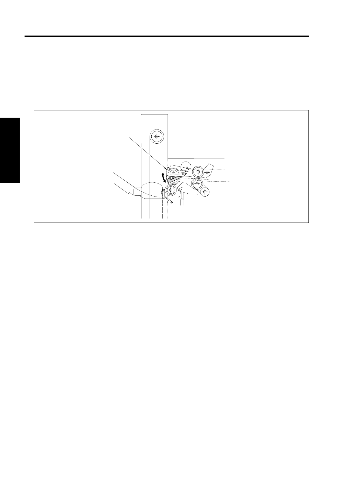
2.2 Operation
2.2.1 Paper exit control
A. Straight paper exit
PS2 (Main body’s fixing ex it sensor)
PS702 (FNS entrance sensor)
II UNIT EXPLANATION
M702
(Paper exit motor)
[1] Dece le ra ted pap er exit
B. Paper exit after stacking
(1) Staple paper exit
M702
(Paper exit motor)
M708 (Stapler motor)
F
R
F
R
600mm/s
230mm/s
600mm/s
230mm/s
[1]
[1]
[1] Stapling completed and starting of paper exit
2-4
Page 19
(2) Shift control
M702
(Paper exit motor)
F
R
PAPER EXIT SECTION
[3]
600mm/s
230mm/s
M703
(Alignment motor /R)
M704
(Alignment motor /F)
M707
(Pressure motor)
[1] Conveying the last paper of the set to the
stack section
[2] Clutch released [5] Starting of paper exit
2.2.2 Paper stack control
While in the sort mode , group mode or s taple mode, p aper convey ed to the paper exit opening i s conveyed to the stack section by the backward rotation of the paper exit roller /A [1]. The paper thus conveyed
is sent up to the stopper [3] by the frictional force of the conveyance belt [2] to be stacked.
Alignment/Shift
Open
Alignment
Shift/Open
Pressure
Release
[1] [2]
[4] [5]
[3]
Clutch locked
[4]
Pressuring of the paper exit roller /A
II UNIT EXPLANATION
[1]
[2]
[3]
2-5
Page 20
PAPER EXIT SECTION
2.2.3 Shutter control
While the tray is going up or down, the shutter [1] is driven by the backward rotation of the M707 (Pressure
motor) to close the pape r exit openi ng. This is to prevent ac cident s such as the hand being caug ht in the
paper exit opening.
If the shutter opens whi le the tray is g oin g up or d own, the MS 702 (Shu tter s wi tch ) is tur ne d o n to sh ut o ff
the power of 24VDC and the FNS is immediately stopped.
II UNIT EXPLANATION
[1]
2-6
Page 21
3. ALIGNMENT SECTION
3.1 Composition
[6] [7] [8]
[5]
[4]
[3]
ALIGNMENT SECTION
FNS CB
[2]
II UNIT EXPLANATION
[1]
Symbol Name Function or method
[1] M704 (Alignment motor /F) Driving of the alignment plate /F
24VDC stepping motor drive
[2] PS710 (Alignment HP sensor /F) HP detection of the alignment plate /F
[3] Alignment plate /F Paper alignment in front of the stack section
[4] M703 (Alignment motor /R) Driving of the alignment plate /R
24VDC stepping motor drive
[5] PS709 (Alignment HP sensor /R) HP detection of the alignment plate /R
[6] Alignment pla te /R Paper alignment in rear of the stack section
[7] Rear stopper Alignment of the rear end of paper in the stack section,
when in the sort, group, and staple mode
[8] PS707 (No paper sensor) No paper detection in the stack section
2-7
Page 22
ALIGNMENT SECTION
3.2 Operation
3.2.1 Paper alignment control
Paper stacked by the paper exit roller /A is aligned by the alignment plates. The alignment plates provided
in front and rear, one for each, are driven independentl y by the M704 (Align ment motor /F) and the M703
(Alignment motor /R). For straight al ignment of the sorting, grou ping, and stapling oper ation, the paper
moves symmetrically in front and in rear, and is aligned at the center by the alignment plates and it moves
asymmetrically while in the shift mode.
The home positions of the ali gnment pl ates are de tected by the PS709 (Al ignmen t HP sensor /R) and the
PS710 (Alignment HP sens or /F).
A. Straight alignment operation
Small size paper such a s 5.5 x 8.5R, A5R or B5R is stacke d and aligned to prevent the p aper from
having uneven edge after being exited.
II UNIT EXPLANATION
During the paper exi t, the alignment plate /F and the alignment plat e /R move symmet rically in front
and in rear based on the center of the alignme nt sect ion with al ternatio ns of ali gnment an d alignm ent
release. Aligned papers are exited for every 5 sheets.
PS2 (Main body’ s fixing exit sensor)
PS702 (FNS entrance sensor)
M702
(Paper exit mot or)
M703
(Alignment motor /R)
M704
(Alignment motor /F)
M707
(Pressure motor)
The 1st paper passes through the FNS
[1]
conveyance section.
The 2nd paper is exited from the main
[2]
body.
The 1st paper is conveyed to the stack
[3]
section.
The paper exit roller /A goes up to prepare
[4]
the conveyance path for the next paper.
600mm/s
F
230mm/s
R
Alignment/Shift
Open
Alignment
Shift/Open
Pressure
Release
[2] [6]
[1]
[4]
[5]
[6]
[7] The 2nd paper turns off the FNS
[8] The 2nd paper is conveyed to the stack
[9] Alignment oper a tion of the 2nd paper
[4]
[7]
Alignment operation of the 1st paper
The 3rd paper is exited from the main
body.
entrance sensor.
section.
[8][3] [5]
[9]
2-8
Page 23

ALIGNMENT SECTION
B. Shift alignment operation
The sheets of paper i n the group of odd numbers are exited fo r every 5 s heets same as the straig ht
alignment operation.
During the alignment operation for even sets of co pies, M703 an d M704 rotate in the sam e direction,
shifting the sheets forward from the center. The aligned sheets are then exited for every 5 sheets.
[1] [2]
PS702 (FNS entrance sensor)
M702
(Paper exit mot or)
M703
(Alignment motor /R)
M704
(Alignment motor /F)
M707
(Pressure motor)
[1] The 1st paper is conveyed to the stack section [3] Alignment
[2] The paper exit roller /A goes up to prepare the
conveyance path for the next paper
600mm/s
F
230mm/s
R
Alignment/Shift
Open
Alignment
Shift/Open
Pressure
Release
[2]
[3]
[4]
[4] Shift
II UNIT EXPLANATION
2-9
Page 24

ALIGNMENT SECTION
C. Staple mode operation
After the same operation is made as that of the strai ght alignme nt, the foll owing ope ratio ns are made
from the last paper of the set.
(1) For 1 position staple
II UNIT EXPLANATION
[1] [8][4][3]
PS702 (FNS entrance sensor)
M702
(Paper exit motor)
M703
(Alignment motor /R)
M704
(Alignment motor /F)
M708 (Stapler motor)
M707
(Pressure motor)
[1] The last paper of the set is conveyed [5] Alignment operation
[2] Paper is conveyed to the stack section [6] Pressuring of the paper exit roller /A
[3] Clutch released [7] Execution of stapling
[4] Clutch locked [8] Paper exit
600mm/s
F
230mm/s
R
Alignment/Shift
Open
Alignment
Shift/Open
Pressure
Release
[2]
[6][5]
[7]
2-10
Page 25

(2) For 2 position staples
ALIGNMENT SECTION
PS702 (FNS entrance sensor)
M702
(Paper exit mot or)
M703
(Alignment motor /R)
M704
(Alignment motor /F)
M705
(Stapler movement motor)
M708 (Stapler motor)
M707
(Pressure motor)
600mm/s
F
230mm/s
R
Alignment/Shift
Open
Alignment
Shift/Open
F
R
Pressure
Release
[1]
[3] [5] [8]
II UNIT EXPLANATION
[7][2] [6][4]
[1] The last paper of the set is conveyed [6] Pressuring of the paper exit roller /A
[2] Paper is conveyed to the stack section [7] Execution of stapli ng in the re ar side
[3] Clutch released [8] The stapler is moved to the front
[4] Alignment oper at ion [9] Execut ion of stapling in the fro nt side
[5] Clutch locked
[9]
2-11
Page 26

STAPLER SECTION
4. STAPLER SECTION
4.1 Composition
II UNIT EXPLANATION
[3]
[5] [6] [7] [8]
[4]
FNS CB
[2]
Symbol Name Function or method
[1] M705 (Stapler movement motor) Moves the stapler to the specified stapling position
24VDC stepping motor drive
[2] PS708 (Stapler unit HP sensor) HP detection of the stapler
[3] Rail Guide rail to move the stapler
[4] Stapler Unit for stapling
[5] PS712 (Stapler HP sensor) HP detection of the M708 (Stapler motor) that drives a staple
[6] PS714 (Stapler ready sensor) Detection of the ready condition for stapling operation
[7] PS713 (Staple detection sensor) Detection of the presence of staples
[8] M708 (Stapler motor) Driving of the stapling operation
24VDC brush motor
[1]
2-12
Page 27

STAPLER SECTION
4.2 Operation
4.2.1 Stapler control
The stapler unit is d riv en th rough the timing belt by the M 705 ( Sta ple r mov em ent moto r). A c co rd ing to t he
form of the rail, the stapler unit can turn round at either end of the rail for oblique stapling.
For 2 positions s tapl in g, t he s ta ple r uni t m ov es to the se co nd pos it ion for stapling afte r st apl in g at the first
position.
[4]
[3]
[2]
[1] Position in back for oblique stapling [3] Position in front for oblique stapling
[2] Position for 1 staple or 2 flat staples
(the position varies depending on the paper size)
A. Stapler movement control
The stapler is normally on s tandby at th e ho me positi on where t he PS7 08 (Stap ler un it HP sen sor) i s
turned on.
According to the s tapling selection from the copier, the M705 (Stapler m ovement motor) moves the
stapler to the position corresponding to the paper size for stapling operation. After completion of printing, the M705 moves th e stapler to the home positio n. The control of the timing for turn ing off the
M705 is made by the number of drive steps after the PS708 is turned off.
[5]
[1]
[4]
Timing belt
[5]
PS708 (Stapler unit HP sensor)
II UNIT EXPLANATION
(1) For 1 position staple
After completion of the al ignme nt oper ation of the l ast pap er, the M707 (Pressure motor ) is tur ned on
to press the paper with the paper exit roller /A. Then, the M708 (Stapler mo tor) is turned on for stapling.
For continuous staplin g, the M70 5 (Stap ler mov ement mo tor) does not mov e and the st apler r emain s
as it was, waiting for the next stapling.
(2) For 2 position staples
After the M705 (Stapler movement mot or) moves to the speci fied position from the fir st stapling pos ition, the M708 is turned on to carr y out the s ec ond stap li ng. When the conti nuo us sta pli ng is s ele ct ed
at this time, the stapler remains at the second stapling position in front.
After completion of printing, the stapler returns to the home position.
2-13
Page 28

STAPLER SECTION
4.2.2 Staple control
When in the stapl e mode, st apling is made by th e drivin g force of th e M708 (Sta pler m otor). Thr ough the
control of the PS712 (Stapler HP sensor), the M708 makes one rotation.
The maximum number of sheets of paper that can be stapled and the operation when the stapling is not
allowed can be set by using the 25 mode DIP SW.
A. No staple detection control
B. Operation after changing a staple cartridge
II UNIT EXPLANATION
When the PS713 (Stapl e detec tion sens or) det ects t he no st aple c onditi on, the m essage o f no stap le
is displayed on the LCD of the main body.
After changing a staple cartridge, the M708 is driven for blank stapling until the PS714 (Stapler ready)
detects staples, to set the staples at the stapling position.
2-14
Page 29

5. TRAY SECTION
5.1 Composition
TRAY SECTION
[5]
[4]
[3]
[2]
[1]
M706
Symbol Name Function or method
[1] PS706 (Tray lower limit sensor) Detection of the lower limit of the tray unit
[2] PS716 (Tray count sensor) Detection of the number of option trays installed
[3] PS703 (Paper exit sensor) Detection of the top face of the paper
[4] PS704 (Paper exit full sensor) Detection of full paper
[5] PS711 (Tray upper limit sensor) Detection of the upper limit of the tray unit
[6] Up/down wire The tray unit up/down operation by driving the tray up/down
motor
M706 Tray up/down motor Up/down drive of the tray unit
24VDC brush motor drive
[6]
FNS CB
II UNIT EXPLANATION
2-15
Page 30

TRAY SECTION
5.2 Operation
5.2.1 Detection of the lower limit of the tray
5.2.2 Tray count
II UNIT EXPLANATION
5.2.3 Tray up/down control while in print operation
When the PS706 (Tray lower limit sensor) is off with the power on, the M706 (Tray up/down motor) rotates
backward to lift down the tray unit. The tray unit stops when the PS706 is turned on.
The number of option tray s i nst alle d (1 tray, 2 trays, or no optional tray ) is cou nted by the fol lo win g ope r ations.
When the PS716 (Tray count sensor) is off during the de tection of the tra y lower limit that is performed
when SW2 (Sub power sw itch) is turned ON, it is jud ged that th er e is no op tio nal tray p rovi ded . And when
the PS716 is on, it is judged that the optional tray 1 is installed. And then the M706 rotates forward to lift
the tray unit by one stage up and stops. At this time, when the PS716 is on, it is judged that the optional
tray 2 is installed.
A. Up/down operation while in printing
(1) Straight (with no stack)
[1] [2]
PS702 (FNS entrance sensor)
M706
(Tray up/ down motor)
[1] The 1st paper [2] The 2nd paper
(2) Sorting or grouping (Shift position paper exit)
PS702 (FNS entrance sensor)
PS703 (Paper exit sensor)
M706
(Tray up/ down motor)
Raise
Lower
Raise
Lower
2-16
Page 31

(3) Stapling
M708 (Stapler motor)
PS703 (Paper exit sensor)
TRAY SECTION
M706
(Tray up/ down motor)
B. Tray full detection operation
When the paper-full is detected, a message indicating the tray is full of paper is displayed on the LCD.
In the automatic tray switching mode, the tray is automatically switched with no message displayed on
the LCD.
(1) When the tray 1 is selected
When the PS703 (Paper exi t sensor) is turned on with the PS706 (Tray lower limit sensor) on, the
paper-full condition is detected.
(2) Other than the tray 1 is selected
When the PS703 (Paper exit sensor) is turned on with the PS704 (Paper exit full sensor) on, the
paper-full condition is detected.
C. Automatic tray switching operation
The automatic tray switching can be set in the 25 mode DIPSW.
Raise
Lower
II UNIT EXPLANATION
(1) When the tray 1, optional tray 1 and 2 are selected
When the paper-full condit ion is detected, the M706 (Tray up/down motor) lifts up the tray until the
PS703 (Paper exit sensor) is turne d off and turned on again, to set the tr ay one stage belo w to the
paper exit position.
(2) When the tray 2 is selected
When the paper-full condi tion is detecte d, the M70 6 (Tray up/down motor) li fts down the tray unt il the
PS716 (Tray count sensor ) is turned on, and then lifts it up until the PS703 (Paper ex it sensor) is
turned on to set the tray 1 at the paper exit position.
2-17
Page 32

TRAY SECTION
II UNIT EXPLANATION
Blank page
2-18
Page 33

III DISASSEMBLY/ASSEMBLY
Caution:
• Make sure the power cord of the copier is
unplugged from the power outlet before disassembly or assembly.
1. EXTERNAL SECTION
1.1 Removing and reinstallin g of the FNS
1. Open the front door, then insert a pen, or the
like, into the hole [1] at the bottom of the FNS.
Note:
• There is a risk of the internal lever becoming
deformed, so do not push it in hard.
EXTERNAL SECTION
2. Pull the FNS forward and remove it.
[1]
III DIS./ASSEMBLY
3-1
Page 34

STAPLER SECTION
2. STAPLER SECTION
2.1 R emoving and reinstalling of the stapler unit
1. Remove the FNS from the main body.
2. Remove the screw [1] from the back of the FNS,
and remove the staple cover [2].
Note:
• Install the cover with the hook [3] put into the
groove [4].
[1]
[4]
[3]
III DIS./ASSEMBLY
3. Remove the connector [1] and 1 grounding
screw [2] from the stapler.
4. Remove the screw [3] and remove the stapler
unit [4].
5. Reinstall the above par ts following the removal
steps in reverse.
[2]
[2]
[4]
[1]
[3]
3-2
[4]
Page 35

2.2 Replacing the stapler cartridge
STAPLER SECTION
1. Operate the stapl er cartr idge repl acing fro m the
operation panel. The stapler unit will move to
the front.
2. Push down the cartr idge ch ange lever [1] of the
stapler.
3. Hold the knob [2] to remove an old cartridge,
and push in a new cartridge securely.
[2]
[1]
III DIS./ASSEMBLY
3-3
Page 36

PAPER EXIT SECTION
3. PAPER EXIT SECTION
3.1 R emoving and reinstalling of the paper exit roller /A
A. Periodically replaced part/cycle
• Paper exit roller /A: Every 600,000 copies.
B. Procedure
1. Remove the FNS from the main body.
2. Take off the cover [1] and 6 screws [2] and
remove the paper conveyance cover [3].
[1][2]
III DIS./ASSEMBLY
3. Remove the spring [1].
Note:
• Do not remove the screws [2] for the spring
adjustment plate.
4. Take out the screw [3] and remove the conveyance driven roller [4].
[3]
[4]
[3]
[1]
[2]
3-4
Page 37

5. Remove the spring [1] and the 2 E-rings [2], and
then remove the cam shaft [3].
6. Take ou t the 2 sc rews [4] and re move the set of
2 plate springs [5].
7. Take out 1 screw [6] and remove the plate [7].
8. Remove the E-ring [8] and remo ve the collar [9]
and the pulley [10].
Note:
• Be careful that the detent pin [1] of the pulley
does not get lost.
PAPER EXIT SECTION
[1] [2] [3] [9][10][11]
[4][5][7][6]
[8]
9. Remove the 5 E-rings [1] and pull out the shaft
[3] of the paper exit roller /A. At this time, be
careful not to drop th e pin [2] in the paper exit
roller /A [4].
10. Replace the paper exit roller /A [4].
11. Rei nstall the above parts fol lowing the removal
steps in reverse.
[1]
[2]
[4]
[3]
[1]
III DIS./ASSEMBLY
3-5
Page 38

PAPER EXIT SECTION
3.2 R emoving and reinstalling of the tray
1. Take out each 3 screws [1] and remove the
cover /F [2] and cover /R [3].
2. Take out each 2 screws [2] from the wire plates
[1] on front and rear.
Note:
• When r emoving the screws, s upport the tray unit
III DIS./ASSEMBLY
with your hands not to let it down.
• When fastening the wire plates, tighten the
screws referring to the marking lines [3] in front
and in rear so that the tray becomes on the level.
[1] [1]
[3]
[1] [1]
[2][2]
[2]
[1]
[3]
3-6
Page 39

3. While taking car e not to l et the roller s [1] down,
remove the tray unit [2] by pulling it down.
4. Reinstall the above parts following the remova l
steps in reverse.
PAPER EXIT SECTION
[1]
[2]
III DIS./ASSEMBLY
3-7
Page 40

PAPER EXIT SECTION
3.3 R emoving and reinstalling of the up/down wire
A. Removing the up/down wire
Note:
• Be sure to ins tall or remove the up /down wires at
one side at a time.
1. Remove the cover / F and cover /R.
2. Remove the tray unit.
3. Loosen the 2 screws [1] and rele ase the pulley
tension plate /F [2] from its fixed position.
4. Remove the E-ring [4] of the lower pulley /F [3].
5. Remove the lower pulley /F [3] and remove the
up/down wire /F [5].
[5]
III DIS./ASSEMBLY
6. Loosen the 2 screws [1] to release the pulley
tension plate /R [2] from its fixed position.
7. Remove the E-ring [4] of the lower pulley /R [3].
8. Remove the lower pulley /R [3], and remove the
up/down wire /R [5].
[2]
[2]
[1]
[4][3]
[1]
[5]
3-8
[3]
[4]
Page 41

B. Installing the up/down wire
1. Set the position of th e casing [1] of the gear to
be put in the front side so that it becomes on the
level.
PAPER EXIT SECTION
[1]
2. With the metal ball [2] which is longer from the
wire plate of the up/down wire [1] put on the
inner flank of the low er pulley /F [3], install the
pulley /F to the shaft [4].
Note:
• Be sure to use the up/down wire with “F”
impressed on its wire plate.
• Be sure to install the pulley /F to the shaft with the
metal ball at the bottom position.
3. Wind the up/down wire o nce arou nd the p ulley /
F counter-clockwise, and string it to the upper
pulley /F [5].
4. Down the up/down wire strung to the upp er pulley /F to the pulley /F and wind it around 4 times
counter-clockwise , and attach the metal ball [6]
on the end to the side of the pulley /F.
Note:
• Avoid the overlap of the up/down wire when
wound around the pulley.
[5]
[1]
[6]
[7]
[3]
[2][4]
III DIS./ASSEMBLY
5. Attach the E-ring [7] and install the pulley /F.
6. Tighten the 2 screws [2] while pulling up the pul-
ley tension plate /F [1], applying 3 kg tension.
3-9
[2]
[1]
Page 42

PAPER EXIT SECTION
7. Set the position of the casing of the gear to be
inserted in the back side so that it bec omes on
the level.
Note:
• Be su re to set the gear installing position accurately to the front side.
[8]
[5]
[9]
[1]
8. With the metal ball [2] which is longer from the
wire plate of the up/down wires [1] put on the
inner flank of the lower pulley /R [3], install the
pulley /R to the shaft [4].
[6]
[7]
[3]
[2] [4]
Note:
• Be sure to use the up/down wire with “R”
impressed on its wire plate.
• Be sure to install the pulley /R to the shaft with the
metal ball at the bottom position.
9. Wind the up/down wire onc e around the pul ley /
R clockwise, and string it to the upper pulley /R
[5].
III DIS./ASSEMBLY
10. Down the up/down wire strung to the upper pul ley /R to the pulley /R and wind it around 4 times
clockwise, and attach the metal ball [6] on the
end to the side of the pulley /R.
Note:
• Avoid the overlap of the up/down wire when
wound around the pulley.
11. Attac h the E-ri ng [7] and install the pul ley /R.
12. Fasten the 2 screws [9] while pu lling up the pul -
ley tension plate /R [8], applying 3 kg tension.
3-10
Page 43

PARTS CATALOG
Model
FS-112
NOVEMBER 2002
KONICA BUSINESS TECHNOLOGIES, INC.
Page 44

Page 45

How to use this catalog
This parts catalog includes illustrations and part numbers for all replacement parts and assemblies used in this model.
Model-specific parts are identified in the illustrations with reference
numbers. Use the reference number to locate the corresponding part
number on the facing page.
Common hardware items, such as screws, nuts, washers, and pins, are
identified in the illustrations with reference letters. Use the reference letter to locate the corresponding part number on the hardware listing in the
lower right hand corner of the facing page.
If you know a part number, but don’t know where the part is used, use
the numerical index to determine the page number and reference number for that part. Because some common parts are used in several
places, there may be more than one entry. Refer to the illustrations to see
where the part may be used.
If you know a part’s description, but don’t know where to look to find
the part number, use the alphabetical index to determine likely page and
reference numbers. Then look at the illustrations to determine that you
have identified the correct part. Locate the part number using the listing
on the opposite page.
Retail pricing that appears with the numerical index, while valid when
this catalog was printed, is subject to change without notice. The prices
are only suggested prices and are provided only for reference. Dealers
may determine their own selling prices. For up-to-date pricing, refer to
current Konica price lists or contact the Konica Parts Distribution Center.
How to order parts
Use standard Konica parts ordering procedures to obtain these parts.
For ordering options, contact Konica’s Parts Distribution Center.
When ordering parts, be sure to specify part numbers exactly as listed in
this catalog.
NOTE: Electrical parts may include previously used components.
Model FS-112 Konica Business Technologies, Inc. Page iii
1st Edition November, 2002
Page 46

This page left blank intentionally.
Page iv Konica Business Technologies, Inc. Model FS-112
November, 2002 1st Edition
Page 47

How to use this catalog . . . . . . . . . . . . . . . . . . . . . . . . . iii
Contents . . . . . . . . . . . . . . . . . . . . . . . . . . . . 1
FS-112 . . . . . . . . . . . . . . . . . . . . . . . . . . . . 2
Wiring . . . . . . . . . . . . . . . . . . . . . . . . . . . . 16
Alphabetical Index . . . . . . . . . . . . . . . . . . . . . . . . . . . 19
Numerical Index . . . . . . . . . . . . . . . . . . . . . . . . . . . . 21
Contents
Model FS-112 Konica Business Technologies, Inc. Page 1
1st Edition November, 2002
Page 48

FS-112
Page 2 Konica Business Technologies., Inc. Model FS-112
November, 2002 1st Edition
Page 49

REF. PART NUMBER DESCRIPTION
NO.
1 13GQ12040 Paper exit cover/front
2 13GQ10022 Main casing/2
3 13GQ12050 Paper exit cover/rear
4 13GQ45021 Conveyance open-close plate
5 14GE-4470 Release arm assembly
6 13GQ12100 Screw cover
7 14GE97020 Staple label/A
8 14GE12010 Open-close cover
9 12AA12100 Magnet catch/A
10 048645260 Stopper rubber
11 13GQ12020 Side cover
12 13GQ12091 External upper plate
13 14GE45210 Conveyance pressure spring/A
14 13GQ45860 Conveyance driven roller/B
15 13GQ-4690 Conveyance driven shaft/A assembly
16 14GE97040 Staple label/B
17 13GL76080 Shaft holder/E
HARDWARE
REF.
LTR.
a 00Z373082
b 00Z353102
c 00Z354122
d 00Z353081
e 00Z712186
f 00Z670406
g 00Z353081
h 00Z163061
PART
NUMBER
Model FS-112 Konica Business Technologies., Inc. Page 3
1st Edition November, 2002
Page 50

FS-112
Page 4 Konica Business Technologies., Inc. Model FS-112
November, 2002 1st Edition
Page 51

REF. PART NUMBER DESCRIPTION
NO.
1 13GQ48010 Paper exit tray/A
2 13GQ48020 Paper exit tray/B
3 13GQ-4910 Paper exit tray/lower assembly
4 13GQ15091 Up-down wire/front
5 13GQ48310 Support plate/front
6 13GQ48080 Up-down roller
7 13GQ48050 Up-down plate/front
8 13GQ48152 Guide part
9 13GQ48300 Tension pulley
10 13GQ48060 Up-down plate/rear
11 13GQ48070 Up-down pulley
12 090075530 Bearing
13 13GQ77130 Rocking gear/D (Z=30)
14 13GQ77120 Rocking gear/C (Z=15/45)
15 300078010 Pin A
16 13GQ76030 Shaft holder/B
17 13GQ80020 FNS driving motor
18 13GQ48320 Support plate/rear
19 13GQ15101 Up-down wire/rear
20 12QV85510 Photosensor
21 13GQ48180 Mount plate/C
22 13GQ48200 Paper exit standard actuator
23 13GQ-4830 Mount plate/D assembly
24 13GQ-1520 Drive mount plate/C assembly
25 13GQ77140 Rocking gear/E (Z=15)
26 13GQ-1540 Tension plate/A assembly
27 13GQ-1510 Drive mount plate/B assembly
HARDWARE
REF.
LTR.
a 00Z670606
b 00Z163061
c 00Z670406
d 00Z254081
e 00Z921930
f 00Z670306
g 00Z353102
h 00Z353081
i 00Z353101
PART
NUMBER
Model FS-112 Konica Business Technologies., Inc. Page 5
1st Edition November, 2002
Page 52

FS-112
Page 6 Konica Business Technologies., Inc. Model FS-112
November, 2002 1st Edition
Page 53

REF. PART NUMBER DESCRIPTION
NO.
1 13GQ48250 Positioning actuator/B
2 13GQ76040 Shaft holder/C
3 13GQ76560 Paper exit pulley (Z=22)
4 13GQ48230 Collar/C
5 13GQ48221 Paper exit driving roller/B
6 12QV85510 Photosensor
7 13GQ48260 Detecting part
8 14GE76600 Motor driving pulley (Z=12)
9 14GE45470 Rotary knob
10 322076010 Paper lift-up lever shaft hold
11 13GQ77040 Conveyance driving gear/1(Z=28)
12 466078010 Pin A
13 13GQ45150 Conveyance driving roller/C
14 13GQ77581 Driving belt/H (L=92)
15 13GQ77020 Conveyance idler gear/1 (Z=18/28)
16 13GQ45480 Collar/A
17 13GQ77540 Driving belt/D (L=129)
18 13GQ77030 Paper exit idler gear (Z=22/33)
19 13GQ77560 Driving belt/F (L=309)
20 13GQ45070 Conveyance driving roller/B
21 14GE76590 Conveyance auxiliary pulley (Z=22)
22 13GQ76540 Conveyance driving pulley/B (Z=18)
23 13GQ76020 Shaft holder/A
24 13GQ45870 Spring spacer
25 13GQ76580 Conveyance driving pulley/A (Z=24)
26 13GQ80510 Cooling fan motor
27 13GQ77181 Paper exit connecting clutch (Z=28/36)
28 13GQ45060 Conveyance driving roller/A
29 13GQ-4340 FNS motor assembly
30 13GQ45620 Hold spring
31 13GQ45820 Conveyance auxiliary roller
32 13GQ77570 Driving belt/G
HARDWARE
REF.
LTR.
a 00Z670606
b 00Z193061
c 00Z163061
d 00Z670406
e 00Z921301
f 00Z183251
g 00Z193161
h 00Z353081
PART
NUMBER
Model FS-112 Konica Business Technologies., Inc. Page 7
1st Edition November, 2002
Page 54

FS-112
Page 8 Konica Business Technologies., Inc. Model FS-112
November, 2002 1st Edition
Page 55

REF. PART NUMBER DESCRIPTION
NO.
1 13GQ45681 Neutralizing cover
2 13GQ45580 Neutralizing brush
3 13GQ76020 Shaft holder/A
4 13GQ45410 Pressure cam
5 13GQ-4320 Connecting shaft assembly
6 13GQ77090 Rocking gear/A (Z=48)
7 322076010 Paper lift-up lever shaft holder
8 13GQ77230 Rocking gear/C (Z=30)
9 13GQ45690 Detecting arm
10 13GQ45421 Positioning actuator/A
11 13GQ77070 Rocking idler/1 (Z=20/40)
12 12QR86010 Interlock switch
13 13GQ45780 Detecting spring
14 13GQ45750 Rocking actuator
15 12QV 85510 Photosensor
16 55GA77670 Toner supply worm
17 13GQ77080 Rocking idler/2 (Z=20/48)
18 13GQ77220 Rocking gear/B (Z=20)
19 13GQ45761 Mount plate/G
20 13GQ80051 FNS motor/3
21 13GQ45931 Cam positioning spring/D
22 14GE46050 Solenoid spring
23 14GE-4410 Solenoid main body assembly
24 14GE-4420 Solenoid slide assembly
HARDWARE
REF.
LTR.
a 00Z193061
b 00Z670406
c 00Z193041
d 00Z252121
e 00Z182641
f 00Z660206
g 00Z163041
h 00Z183081
i 00Z353081
j 00Z473043
PART
NUMBER
Model FS-112 Konica Business Technologies., Inc. Page 9
1st Edition November, 2002
Page 56

FS-112
Page 10 Konica Business Technologies., Inc. Model FS-112
November, 2002 1st Edition
Page 57

REF. PART NUMBER DESCRIPTION
NO.
1 13GQ98040 Cam auxiliary sheet
2 13GQ45430 Paper exit pressure spring
3 13GQ77550 Driving belt/E (L=195)
4 13GQ45490 Collar/B
5 13GQ76550 Paper exit driving pulley/A (Z=12)
6 466078010 Pin A
7 13GQ45090 Paper exit driven roller/A
8 13GQ76010 Paper exit shaft holder
9 13GQ45191 Paper exit driving roller/A
10 13GQ45050 Conveyance rocking plate
11 13GQ45511 Toque limiter
12 454078050 Pin (Cleaner A)
13 13GQ76020 Shaft holder/A
14 13GQ45600 Conveyance auxiliary sheet/A
15 13GQ45450 Adjusting spring
16 13GQ45610 Conveyance auxiliary sheet/B
17 13GQ-4730 Conveyance pressure spring/B assembly
18 12QV85510 Photosensor
19 13GQ45910 Finisher cushion
20 12QR86010 Interlock switch
21 13GQ45301 Spring
HARDWARE
REF.
LTR.
a 00Z670206
b 00Z670406
c 00Z193041
d 00Z353081
PART
NUMBER
Model FS-112 Konica Business Technologies., Inc. Page 11
1st Edition November, 2002
Page 58

FS-112
Page 12 Konica Business Technologies., Inc. Model FS-112
November, 2002 1st Edition
Page 59

REF. PART NUMBER DESCRIPTION
NO.
1 13GQ80011 FNS collect motor
2 25AA52090 Stopper sheet
3 12QV85510 Photosensor
4 13GQ60171 Paper detecting actuator
5 13GQ90011 FNS I/F wiring
6 13GQ-6080 Paper regulating plate/rear assembly
7 13GQ60010 Paper regulating/front
8 14GE-6150 Paper positioning plate/front
9 13GQ60051 Paper regulating spring
10 13GQ60251 Wiring fixed plate
11 13GQ60211 Detecting spring
12 14GE-6140 Paper positioning plate/rear assembly
13 12QR86010 Interlock switch
14 14GE-9010 FNS control unit
15 13GQ77010 Regulating gear (Z=28/55)
16 25AA52140 Belt holder/B
17 13GQ77190 Regulating gear/B (Z=22/37)
18 13GQ77160 Regulating idler (Z=64)
19 13GQ77510 Driving belt/A (L=380)
20 13GQ77520 Driving belt/B (L=406)
21 13GQ76510 Idler pulley (Z=28)
22 13GQ10170 Switch plate
HARDWARE
REF.
LTR.
a 00Z670606
b 00Z670406
c 00Z183061
d 00Z921931
e 00Z670306
f 00Z163061
g 00Z670206
h 00Z660206
i 00Z353101
j 00Z182081
k 00Z353081
PART
NUMBER
Model FS-112 Konica Business Technologies., Inc. Page 13
1st Edition November, 2002
Page 60

FS-112
Page 14 Konica Business Technologies., Inc. Model FS-112
November, 2002 1st Edition
Page 61

REF. PART NUMBER DESCRIPTION
NO.
1 14GEK0020 Cartridge case
3 13GQ50090 Oscillate cam
4 13GQ50080 Slide plate
5 13GQ-1220 Cover/lower assembly
6 13GQ50051 Fixed plate
7 13GQ50070 Driving plate
8 25AA52140 Belt holder/B
9 13GQ77210 Staple driving gear (Z=19/55)
10 12QR77010 Staple driving gear (Z=28/55)
11 13GQ50170 Click part
12 13GQ80031 FNS motor/1
13 13GQ77530 Driving belt/C (L=741)
14 13GQ50230 Fixed block
15 14GEK0010 Staples
16 12QV85510 Photosensor
17 14GE90100 Relay wiring/2
18 13GQ76570 Idler pulley/2 (Z=19)
19 13GQ10140 Main lock spring
20 13GQ10120 Main lock claw
21 14GE50120 Wiring cover
22 14GE-5050 Staple mount plate assembly
23 13GQ50271 Fixed part
24 14GE50180 Oscillate collar
25 14GE50100 Staple board
HARDWARE
REF.
LTR.
a 00Z193061
b 00Z670606
c 00Z670406
d 00Z183061
e 00Z921931
f 00Z163061
g 00Z922410
i 00Z353102
j 00Z353081
PART
NUMBER
Model FS-112 Konica Business Technologies., Inc. Page 15
1st Edition November, 2002
Page 62

WIRING
Page 16 Konica Business Technologies., Inc. Model FS-112
November, 2002 1st Edition
Page 63

REF. PART NUMBER DESCRIPTION
NO.
1 13GQ90011 FNS I/F wiring
2 13GQ90021 Motor wiring/1
3 13GQ90031 Motor wiring/2
4 14GE90100 Relay wiring/2
5 13GQ90110 Interlock wiring/1
Model FS-112 Konica Business Technologies., Inc. Page 17
1st Edition November, 2002
Page 64

This page left blank intentionally.
Page 18 Konica Business Technologies, Inc. Model FS-112
November, 2002 1st Edition
Page 65

ALPHABETICAL INDEX
PART PAGE REF.
DESCRIPTION NO. NO.
A
Adjusting spring . . . . . . 11 15
B
Bearing . . . . . . . . . . . 5 12
Belt holder/B . . . . . . . . 13 16
Belt holder/B . . . . . . . . 15 8
C
Cam auxiliary sheet . . . . 11 1
Cam positioning spring/D . 9 21
Cartridge case . . . . . . . 15 1
Click part . . . . . . . . . . 15 11
Collar/A . . . . . . . . . . 7 16
Collar/B . . . . . . . . . . 11 4
Collar/C . . . . . . . . . . 7 4
Connecting shaft assembly 9 5
Conveyance auxiliary pulley
(Z=22) . . . . . . . . . 7 21
Conveyance auxiliary roller 7 31
Conveyance auxiliary sheet/A 11 14
Conveyance auxiliary sheet/B 11 16
Conveyance driven roller/B 3 14
Conveyance driven shaft/A
assembly . . . . . . . . 3 15
Conveyance driving gear/1
(Z=28) . . . . . . . . . 7 11
Conveyance driving pulley/A
(Z=24) . . . . . . . . . 7 25
Conveyance driving pulley/B
(Z=18) . . . . . . . . . 7 22
Conveyance driving roller/A 7 28
Conveyance driving roller/B 7 20
Conveyance driving roller/C 7 13
Conveyance idler gear/1
(Z=18/28) . . . . . . . 7 15
Conveyance open-close plate 3 4
Conveyance pressure
spring/A . . . . . . . . 3 13
Conveyance pressure
spring/B assembly . . . 11 17
Conveyance rocking plate . 11 10
Cooling fan motor . . . . . 7 26
Cover/lower assembly . . . 15 5
D
Detecting arm . . . . . . . 9 9
Detecting part . . . . . . . 7 7
Detecting spring . . . . . . 9 13
Detecting spring . . . . . . 13 11
Drive Mount plate/B
assembly . . . . . . . . 5 27
Drive Mount plate/C
assembly . . . . . . . . 5 24
Driving belt/A (L=380) . . . 13 19
Driving belt/B (L=406) . . . 13 20
Driving belt/C (L=741) . . . 15 13
PART PAGE REF.
DESCRIPTION NO. NO.
Driving belt/D (L=129) . . . 7 17
Driving belt/E (L=195) . . . 11 3
Driving belt/F (L=309) . . . 7 19
Driving belt/G . . . . . . . . 7 32
Driving belt/H (L=92) . . . . 7 14
Driving plate . . . . . . . . 15 7
E
External upper plate . . . . 3 12
F
FNS I/F wiring . . . . . . . 13 5
FNS I/F wiring . . . . . . . 17 1
FNS collect motor . . . . . 13 1
FNS control unit . . . . . . 13 14
FNS driving motor . . . . . 5 17
FNS motor/1 . . . . . . . . 15 12
FNS motor/3 . . . . . . . . 9 20
FNS motor assembly . . . . 7 29
Finisher cushion . . . . . . 11 19
Fixed block . . . . . . . . . 15 14
Fixed part . . . . . . . . . . 15 23
Fixed plate . . . . . . . . . 15 6
G
Guide part . . . . . . . . . 5 8
H
Hold spring . . . . . . . . . 7 30
I
Idler pulley (Z=28) . . . . . 13 21
Idler pulley/2 (Z=19) . . . . 15 18
Interlock switch . . . . . . . 9 12
Interlock switch . . . . . . . 11 20
Interlock switch . . . . . . . 13 13
Interlock wiring/1 . . . . . . 17 5
M
Magnet catch/A . . . . . . . 3 9
Main casing/2 . . . . . . . 3 2
Main lock claw . . . . . . . 15 20
Main lock spring . . . . . . 15 19
Motor driving pulley (Z=12) . 7 8
Motor wiring/1 . . . . . . . 17 2
Motor wiring/2 . . . . . . . 17 3
Mount plate/C . . . . . . . 5 21
Mount plate/D assembly . . 5 23
Mount plate/G . . . . . . . 9 19
PART PAGE REF.
DESCRIPTION NO. NO.
N
Neutralizing brush . . . . . 9 2
Neutralizing cover . . . . . . 9 1
O
Open-close cover . . . . . . 3 8
Oscillate cam . . . . . . . . 15 3
Oscillate collar . . . . . . . 15 24
P
Paper detecting actuator . . 13 4
Paper exit connecting clutch
(Z=28/36) . . . . . . . . 7 27
Paper exit cover/front . . . . 3 1
Paper exit cover/rear . . . . 3 3
Paper exit driven roller/A . . 11 7
Paper exit driving pulley/A
(Z=12) . . . . . . . . . 11 5
Paper exit driving roller/A . . 11 9
Paper exit driving roller/B . . 7 5
Paper exit idler gear
(Z=22/33) . . . . . . . . 7 18
Paper exit pressure spring . 11 2
Paper exit pulley (Z=22) . . 7 3
Paper exit shaft holder . . . 11 8
Paper exit standard actuator 5 22
Paper exit tray/A . . . . . . 5 1
Paper exit tray/B . . . . . . 5 2
Paper exit tray/lower
assembly . . . . . . . . 5 3
Paper lift-up lever shaft
holder . . . . . . . . . . 7 10
Paper lift-up lever shaft
holder . . . . . . . . . . 9 7
Paper positioning plate/front 13 8
Paper positioning plate/rear
assembly 13 12
Paper regulating plate/rear
assembly . . . . . . . . 13 6
Paper regulating spring . . . 13 9
Paper regulating/front . . . . 13 7
Photosensor . . . . . . . . 5 20
Photosensor . . . . . . . . 7 6
Photosensor . . . . . . . . 9 15
Photosensor . . . . . . . . 11 18
Photosensor . . . . . . . . 13 3
Photosensor . . . . . . . . 15 16
Pin (Cleaner A) . . . . . . . 11 12
Pin A . . . . . . . . . . . . 5 15
Pin A . . . . . . . . . . . . 7 12
Pin A . . . . . . . . . . . . 11 6
Positioning actuator/A . . . 9 10
Positioning actuator/B . . . 7 1
Pressure cam . . . . . . . . 9 4
R
Regulating gear (Z=28/55) . 13 15
Model FS-112 Konica Business Technologies, Inc. Page 19
1st Edition November, 2002
Page 66

PART PAGE REF.
DESCRIPTION NO. NO.
Regulating gear/B (Z=22/37) 13 17
Regulating idler (Z=64) . . . 13 18
Relay wiring/2 . . . . . . . 15 17
Relay wiring/2 . . . . . . . 17 4
Release arm assembly . . . 3 5
Rocking actuator . . . . . . 9 14
Rocking gear/A (Z=48) . . . 9 6
Rocking gear/B (Z=20) . . . 9 18
Rocking gear/C (Z=15/45) . 5 14
Rocking gear/C (Z=30) . . . 9 8
Rocking gear/D (Z=30) . . . 5 13
Rocking gear/E (Z=15) . . . 5 25
Rocking idler/1 (Z=20/40) . . 9 11
Rocking idler/2 (Z=20/48) . . 9 17
Rotary knob . . . . . . . . 7 9
S
Screw cover . . . . . . . . 3 6
Shaft holder/A . . . . . . . 7 23
Shaft holder/A . . . . . . . 9 3
Shaft holder/A . . . . . . . 11 13
PART PAGE REF.
DESCRIPTION NO. NO.
Shaft holder/B . . . . . . . . 5 16
Shaft holder/C . . . . . . . 7 2
Shaft holder/E . . . . . . . . 3 17
Side cover . . . . . . . . . . 3 11
Slide plate . . . . . . . . . . 15 4
Solenoid main body
assembly . . . . . . . . 9 23
Solenoid slide assembly . . 9 24
Solenoid spring . . . . . . . 9 22
Spring . . . . . . . . . . . . 11 21
Spring spacer . . . . . . . . 7 24
Staple board . . . . . . . . 15 25
Staple driving gear (Z=19/55) 15 9
Staple driving gear (Z=28/55) 15 10
Staple label/A . . . . . . . . 3 7
Staple label/B . . . . . . . . 3 16
Staple mount plate assembly 15 22
Staples . . . . . . . . . . . 15 15
Stopper rubber . . . . . . . 3 10
Stopper sheet . . . . . . . . 13 2
Support plate/front . . . . . 5 5
Support plate/rear . . . . . 5 18
Switch plate . . . . . . . . . 13 22
PART PAGE REF.
DESCRIPTION NO. NO.
T
Tension plate/A assembly . 5 26
Tension pulley . . . . . . . 5 9
Toner supply worm . . . . 9 16
Toque limiter . . . . . . . . 11 11
U
Up-down plate/front . . . . 5 7
Up-down plate/rear . . . . 5 10
Up-down pulley . . . . . . 5 11
Up-down roller . . . . . . . 5 6
Up-down wire/front . . . . 5 4
Up-down wire/rear . . . . . 5 19
W
Wiring cover . . . . . . . . 15 21
Wiring fixed plate . . . . . 13 10
Page 20 Konica Business Technologies, Inc. Model FS-112
November, 2002 1st Edition
Page 67

NUMERICAL INDEX
PART PAGE REF.
NUMBER NO. NO.
048645260 3 10
090075530 5 12
12AA12100 3 9
12QR77010 15 10
12QR86010 9 12
12QR86010 11 20
12QR86010 13 13
12QV 85510 9 15
12QV85510 5 20
12QV85510 7 6
12QV85510 11 18
12QV85510 13 3
12QV85510 15 16
13GL76080 3 17
13GQ-1220 15 5
13GQ-1510 5 27
13GQ-1520 5 24
13GQ-1540 5 26
13GQ-4320 9 5
13GQ-4340 7 29
13GQ-4690 3 15
13GQ-4730 11 17
13GQ-4830 5 23
13GQ-4910 5 3
13GQ-6080 13 6
13GQ10022 3 2
13GQ10120 15 20
13GQ10140 15 19
13GQ10170 13 22
13GQ12020 3 11
13GQ12040 3 1
13GQ12050 3 3
13GQ12091 3 12
13GQ12100 3 6
13GQ15091 5 4
13GQ15101 5 19
13GQ45021 3 4
13GQ45050 11 10
13GQ45060 7 28
13GQ45070 7 20
13GQ45090 11 7
13GQ45150 7 13
13GQ45191 11 9
13GQ45301 11 21
13GQ45410 9 4
13GQ45421 9 10
13GQ45430 11 2
13GQ45450 11 15
13GQ45480 7 16
13GQ45490 11 4
13GQ45511 11 11
13GQ45580 9 2
13GQ45600 11 14
13GQ45610 11 16
13GQ45620 7 30
13GQ45681 9 1
13GQ45690 9 9
13GQ45750 9 14
13GQ45761 9 19
13GQ45780 9 13
13GQ45820 7 31
13GQ45860 3 14
13GQ45870 7 24
13GQ45910 11 19
PART PAGE REF.
NUMBER NO. NO.
13GQ45931 9 21
13GQ48010 5 1
13GQ48020 5 2
13GQ48050 5 7
13GQ48060 5 10
13GQ48070 5 11
13GQ48080 5 6
13GQ48152 5 8
13GQ48180 5 21
13GQ48200 5 22
13GQ48221 7 5
13GQ48230 7 4
13GQ48250 7 1
13GQ48260 7 7
13GQ48300 5 9
13GQ48310 5 5
13GQ48320 5 18
13GQ50051 15 6
13GQ50070 15 7
13GQ50080 15 4
13GQ50090 15 3
13GQ50170 15 11
13GQ50230 15 14
13GQ50271 15 23
13GQ60010 13 7
13GQ60051 13 9
13GQ60171 13 4
13GQ60211 13 11
13GQ60251 13 10
13GQ76010 11 8
13GQ76020 7 23
13GQ76020 9 3
13GQ76020 11 13
13GQ76030 5 16
13GQ76040 7 2
13GQ76510 13 21
13GQ76540 7 22
13GQ76550 11 5
13GQ76560 7 3
13GQ76570 15 18
13GQ76580 7 25
13GQ77010 13 15
13GQ77020 7 15
13GQ77030 7 18
13GQ77040 7 11
13GQ77070 9 11
13GQ77080 9 17
13GQ77090 9 6
13GQ77120 5 14
13GQ77130 5 13
13GQ77140 5 25
13GQ77160 13 18
13GQ77181 7 27
13GQ77190 13 17
13GQ77210 15 9
13GQ77220 9 18
13GQ77230 9 8
13GQ77510 13 19
13GQ77520 13 20
13GQ77530 15 13
13GQ77540 7 17
13GQ77550 11 3
13GQ77560 7 19
13GQ77570 7 32
PART PAGE REF.
NUMBER NO. NO.
13GQ77581 7 14
13GQ80011 13 1
13GQ80020 5 17
13GQ80031 15 12
13GQ80051 9 20
13GQ80510 7 26
13GQ90011 13 5
13GQ90011 17 1
13GQ90021 17 2
13GQ90031 17 3
13GQ90110 17 5
13GQ98040 11 1
14GE-4410 9 23
14GE-4420 9 24
14GE-4470 3 5
14GE-5050 15 22
14GE-6140 13 12
14GE-6150 13 8
14GE-9010 13 14
14GE12010 3 8
14GE45210 3 13
14GE45470 7 9
14GE46050 9 22
14GE50100 15 25
14GE50120 15 21
14GE50180 15 24
14GE76590 7 21
14GE76600 7 8
14GE90100 15 17
14GE90100 17 4
14GE97020 3
Model FS-112 Konica Business Technologies, Inc. Page 21
1st Edition November, 2002
Page 68

This page left blank intentionally.
Page 22 Konica Business Technologies, Inc. Model FS-112
November, 2002 1st Edition
Page 69

FS-112
INSTALLATION PROCEDURE
Finisher
I. Accessory parts
No. Name Shape Q’ty
1 Finisher
II. Caution for handling
Applied Machine : Konica 7145
III. Preparation
1. Remove each locking tapes.
Front
1
q
Rear
r
t
r
e
w
y
1. Do not lift the Finisher by holding the positions
shown in the figure because that can damage the
machine.
DO NOT hold
Incorrect
Front
DO NOT hold
Correct
Front
Left side
u
o
i
t
2. Grip the Finisher at the front and rear to lift it.
Caution:
Do NOT touch the tray elevation motor (indicated
as a circle in the illustration above).
E-1
14GE97010
Page 70

2. Open the Finisher front door and remove the
cushion sheet, locking tape (1 location) and
cushion material.
Cushion sheet
Locking tape
Cushion material
IV. Installation procedure
1. Turn OFF the power.
2. Remove the optional ET-101 (paper exit kit), if it
is mounted.
Caution:
Proceed to procedure 3 on the next page if there
is no ET-101.
(1) Remove the paper exit tray.
Paper exit tray
3. Remove the stapler locking material(4 screws),
cushion material, and locking tape.
Cushion material
Locking tape
Locking material
Screws
(2) Remove the paper exit side cover. (2 screws)
Paper exit side cover
Screws
(3) Remove the front cover/left. (1 screw)
Front cover /left
E-2
Screw
Page 71

(4) Install the screws to the positions shown in the
figure below. (Screws before installing ET-101:
TP screw M3 x 6)
TP screw M3x6
(5) Remove the side stay. (4 screws)
Screws
Screws
4. Install the Finisher to the main body.
5. Turn on the power switch, then press [OUTPUT]
key to verify that the Finisher is detected on the
screen.
Side stay
3. Remove the cover from the main body. (1 screw)
Screw
Main body rear cover
E-3
Page 72

Blank page
 Loading...