

Page 1

SERVICE MANUAL
Models
FS-111/FS-211
JANUARY 2004
CSM-FS111/211
KONICA MINOLTA BUSINESS SOLUTIONS U.S.A., INC.
Page 2

Page 3

FS-111/211
SERVICE MANUAL
JANUARY 2004
Used on Konica Models
7085/FORCE 85: FS-111/211
7255/7272: FS-111
Page 4

IMPORTANT NOTICE
Because of the possible hazards to an inexperienced
person servicing this equipment, as well as the risk of
damage to the equipment, Konica Minolta Business
Solutions U.S.A., Inc. strongly recommends that all
servicing be performed by Konica-trained service technicians only.
Changes may have been made to this equipment to
improve its performance after this service manual was
printed. Accordingly, Konica Minolta Business Solutions U.S.A., Inc., makes no representations or warranties, either expressed or implied, that the information contained in this service manual is complete or
accurate. It is understood that the user of this manual
must assume all risks or personal injury and/or damage to the equipment while servicing the equipment for
which this service manual is intended.
Corporate Publishing Department
© 2004, KONICA MINOLTA BUSINESS SOLUTIONS U.S.A., INC.
All rights reserved.
Printed in U.S.A.
Page 5

CONTENTS
CONTENTS
SAFETY AND IMPORTANT WARNING ITEMS
Refer to the 7155/7165/7255/7272 Service Manual
1. OUTLINE
FS-111/FS-211 PRODUCT SPECIFICATIONS ...... 1-1
CENTER CROSS SECTION ................................... 1-3
DRIVE SYSTEM DIAGRAM .................................... 1-4
[1] Paper Conveyance Drive ............................ 1-4
[2] Stacker Drive .............................................. 1-5
[3] Folding Drive (FS-211 only) ........................ 1-6
PAPER CONVEYANCE PROCESS ....................... 1-7
[1] Paper Conveyance Process ....................... 1-7
[2] Non-Sort Mode............................................ 1-8
[3] Sort, Group Mode ....................................... 1-9
[4] Sub-tray Mode .......................................... 1-10
[5] Staple Mode .............................................. 1-11
[6] Booklet Mode (FS-211 only) ..................... 1-13
2. UNIT EXPLANATION
EXTERNAL SECTION ............................................ 2-1
[1] Composition ................................................ 2-1
[2] Mechanisms ................................................ 2-1
CONVEYANCE SECTION ...................................... 2-2
[1] Composition ................................................ 2-2
[2] Mechanisms ................................................ 2-3
[3] M1 (FNS Conveyance) Control ................... 2-7
[4] Gate Control................................................ 2-9
[5] M13 (Stacker Entrance) Control ............... 2-12
[6] M5 (Alignment Plate/Upper) Control ......... 2-14
[7] M15 (Alignment Plate/Lower) Control
(FS-211 only) ............................................ 2-15
[8] M2 (Roller Shift) Control ........................... 2-16
[9] M7 (Paper Exit Roller) Control .................. 2-17
[10] SD4 (Paper Exit Opening) Control ............ 2-19
[11] M8 (Paper Exit Opening) Control .............. 2-20
STAPLER UNIT ..................................................... 2-21
[1] Composition .............................................. 2-21
[2] Mechanisms .............................................. 2-22
[3] Stapler Control .......................................... 2-26
MAIN TRAY UNIT ................................................. 2-30
[1] Composition .............................................. 2-30
[2] Mechanisms .............................................. 2-30
[3] Main Tray Up/Down Control...................... 2-31
FOLDING UNIT (FS-211 ONLY) ........................... 2-32
[1] Composition .............................................. 2-32
[2] Mechanisms .............................................. 2-33
[3] Folding-Unit Control .................................. 2-34
1 OUTLINE
2 UNIT EXPLANATION
3 DIS./ASSEMBLY
3. DISASSEMBLY/ASSEMBLY
EXTERNAL SECTION ............................................ 3-1
[1] Removing and Reinstalling
the Rear Cover............................................ 3-1
[2] Removing and Reinstalling
the Front Cover ........................................... 3-1
[3] Removing and Reinstalling
the Top Cover ............................................. 3-1
Page 6

CONTENTS
1 OUTLINE
2 UNIT EXPLANATION
3 DIS./ASSEMBLY
[4] Removing and Reinstalling
the Paper Exit Cover ................................... 3-2
[5] Removing and Reinstalling
the Main Tray .............................................. 3-2
[6] Removing and Reattaching
the Front Side Cover ................................... 3-3
[7] Removing and Reinstalling
the Paper Exit Stopper Plate ....................... 3-3
PAPER FEED UNIT ................................................ 3-5
[1] Replacing a Paper Exit Roller
(Sponge Roller) ........................................... 3-5
[2] Removing and Reinstalling
the Paper Exit Unit/Shift Unit ...................... 3-5
[3] Removing and Reinstalling
the Stacker/Stapler Unit .............................. 3-8
STAPLER UNIT ..................................................... 3-11
[1] Exchanging the clincher (FS-211 only) ..... 3-11
[2] Removing and Reinstalling a Stapler
(For FS-111) ............................................. 3-12
[3] Removing and Reinstalling a Stapler
(For FS-211) ............................................. 3-12
MAIN TRAY SECTION .......................................... 3-14
[1] Removing and Reinstalling
the Up-Down Stay ..................................... 3-14
[2] Exchanging the Up-Down Wire ................. 3-14
FOLDING UNIT (FS-211 ONLY) ........................... 3-16
[1] Removing and Reinstalling
the Folding Unit ......................................... 3-16
[2] Removing and Reinstalling
the Adjustment Cover ............................... 3-17
Page 7

SAFETY WARNINGS
[1] Modifications Not Authorized by
Konica Minolta
Konica Minolta equipment is renowned for their high
reliability. This reliability is achieved through high-quality
design and a solid service network.
Unauthorized modifications involve a high risk of degrading performance and safety. Such modifications are therefore strictly prohibited. The points listed below are not
exhaustive, but they illustrate the reasoning behind this
policy.
PROHIBITED ACTIONS :
(1) Using extension cables or a different power cord
than specified by Konica Minolta.
(2) Using other fuses than specified by Konica
Minolta. Safety will not be assured, leading to a
risk of fire and injury.
(3) Disabling fuses or bridging fuse terminals with
wire, metal clips, solder or similar. (This applies
also to thermal fuses.)
(4) Removing air filters (except for replacement).
(5) Disabling relay functions (such as wedging pa-
per between relay contacts, etc.).
(6) Disabling safety functions (interlocks, safety cir-
cuits, etc.). Safety will not be assured, leading to
a risk of fire and injury.
(7) Performing actions to equipment not described
in the instruction manual or the service hand-
book.
(8) Using parts other than specified by Konica
Minolta.
[2] Checkpoints When Performing On-
site Service
Konica Minolta equipment is extensively tested before
shipping, to ensure that all applicable safety standards
are met, in order to protect the customer and customer
engineer from the risk of injury. However, in daily use, any
electrical equipment may be subject to parts wear and
eventual failure. In order to maintain safety and reliability,
the customer engineer must perform regular safety checks.
(3) Be sure to disconnect the power cord of the
equipment from the AC outlet.
Simply turning off the power switch is not sufficient, because paper feed units or other electrical equipment may be powered also when the
power switch is turned off.
(4) Proceed with special care when performing op-
eration checks or adjustment while the unit is
powered. When carrying out operation checks or
adjustment while external covers are removed,
the risk of electrical shock exists when touching
parts which carry high voltage or electrical charge.
The risk of injury exists when touching moving
parts such as gears or chains.
2. Safety Checkpoints
The following list is not exhaustive, but it includes actions
which must be carried out at every on-site service.
CAUTION:
(1) Check external covers and the frame for sharp
edges, burrs, or nicks.
(2) Check external covers and hinges for loosening
or damage.
(3) Check wiring for squeezing or damage.
(4) Check power cord for insulation problems (con-
ductor must not be exposed).
(5) Check power cord and cable ties etc. for loosen-
ing from frame.
WARNING:
(1) Verify that the equipment is properly grounded. If
a problem is detected, establish a proper ground
connection.
(2) Connecting the ground lead to an improper point
such as listed below results in a risk of explosion
and electric shock.
Unsuitable ground points:
- Gas pipe
- Lightning rod
- Telephone line ground
- Plastic water pipe or water pipe or faucet that
has not been approved by authorities for
grounding use
1. Advance Preparation for Safety Checks
CAUTION:
(1) Wear clothing that facilitates work and is de-
signed for safety.
(2) Carry out all procedures carefully to prevent in-
jury.
3. Description of Safety Checks
CAUTION:
(1) Before performing safety check work, read all
relevant documentation (service handbook, technical notices, etc.) and proceed according to the
prescribed procedure, using only the prescribed
tools. Do not carry out any adjustments not
described in the documentation.
Page 8

(2) If the power cord is damaged, replace it only with
the specified power cord. If the power cord insulation has been damaged and there are exposed
sections, short- circuits and overheating may
occur, leading to a serious fire risk.
(3) Do not route the power cord so that it can be
stepped on or pinched. Otherwise overheating
may occur, leading to a serious fire risk.
(4) When disconnecting any cables, always grasp
the connector and not the cable (especially in the
case of AC and high-voltage leads).
(5) Carefully remove all toner remnants from electri-
cal parts, electrodes, etc.
(6) Make sure that wiring cannot come into contact
with sharp edges, burrs, or other pointed parts.
(7) Double-check to make sure that all screws, com-
ponents, wiring, connectors, etc. that were removed for safety check maintenance have been
reinstalled in the original location. (Pay special
attention to forgotten connectors, pinched cables,
forgotten screws, etc.)
(8) When installation and preventive maintenance,
verify that the power cord has been securely
plugged into the AC outlet. Contact problems
may lead to increased resistance, overheating,
and the risk of fire.
WARNING:
Before disassembling or adjusting the equipment, make sure that the power cord has been
disconnected.
[4] Measures to Take in Case of an
Accident
(1) If an accident has occurred, the distributor who has
been notified first must immediately take emergency
measures to provide relief to affected persons and to
prevent further damage.
(2) If a report of a serious accident has been received
from a customer, an on-site evaluation must be
carried out quickly and Konica Minolta must be
notified.
(3) To determine the cause of the accident, conditions
and materials must be recorded through direct onsite checks, in accordance with instructions issued
by Konica Minolta.
(4) For reports and measures concerning accidents,
consult your superior, and follow the regulations set
in "Standards for the Control Program for Measures
Against Electrical Equipment Accidents".
[5] Conclusion
(1) Safety of users and customer engineers depends
highly on accurate maintenance and administration.
Therefore, safety can be maintained by the appropriate by the proper daily service work conducted by the
customer engineer.
(2) When performing service, equipment on the site
must be tested for safety. The customer engineer
must verify the safety of parts and ensure appropriate management of the equipment.
[3]
Handling of Materials for Servicing
CAUTION: Alcohol-based and acetone- based
cleaners are highly flammable and
must be handled with care. When
using these materials for cleaning
parts, observe the following precau-
tions.
(1) Disconnect the power cord from the AC outlet.
(2) Use only a small amount of cleaner at a time and
take care not to spill any liquid. If this happens,
immediately wipe it off.
(3) Perform cleaning only in an environment where
sufficient ventilation is assured. Breathing large
quantities of organic solvents can lead to discomfort.
(4) Do not replace the cover or turn the unit on before
any solvent remnants on the cleaned parts have
fully evaporated.
Page 9

1
OUTLINE
1 OUTLINE
Page 10

1 OUTLINE
Blank page
Page 11
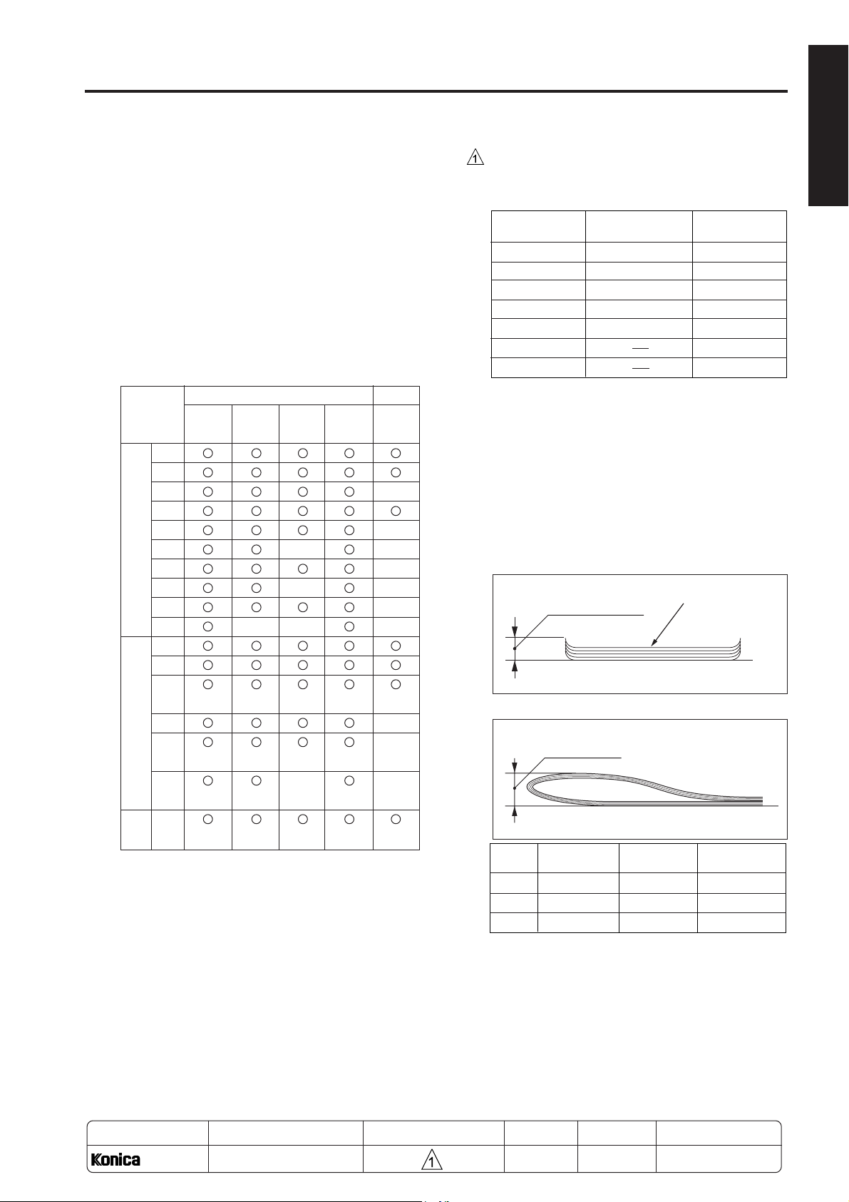
FS-111/FS-211 PRODUCT SPECIFICATIONS
Folded
Pages
A3, 11x17
0 to 5
11 to 16
6 to 10
25mm or less
Not specified*
50mm or less
A4R, 8.5x11R
25mm or less
Not specified*
B4, 8.5x14
25mm or less
50mm or less
Not specified*
Not specified*
Original Main-tray
capacity Pages
A3, 11x17
Other paper types
2 to 9
41 to 50
31 to 40
21 to 30
10 to 20
100 (50) stacks
50 stacks
20 stacks
25 stacks
30 stacks
50 stacks
50 stacks
30 stacks
25 stacks
20 stacks
51 to 60
61 to 100
15 stacks
10 stacks
*
FS-111 only
( ) A5, 5.5x8.5 only
*
*
FS-111/FS-211
[1] Type
FS-111: Finishing device implementing offset
collation (sort,group), stapling, and
sub-tray eject
FS-211: Finishing device implementing offset
collation(sort,group), stapling, sub-tray
eject (booklet), stapling-and-folding,
and folding
[2] Functions
Type of Paper: Same as the main body.
Paper Size:
FS-111/211
Non sort Sort/ Staple Sub-tray Booklet
group
A3
B4
F4
A4R
A4
A/B
B5R
Stan-
B5
dard
A5R
A5
B6R
11x17
8.5x14
8.5x
11R
By
8.5x11
inch
5.5x
8.5R
5.5x
8.5
Wide
paper
FS-211only
Staple Mode:
Maximum 1000 sheets (same-size
sheets only)
Booklet Mode (FS-211 only):
• Stapling-and-folding
20 booklets of 5 folded sheets each (20 pages/
booklet; eq. to 400 pages)
• Folding
33 booklets of 3 folded sheets each (12 pages/
booklet; eq. to 396 pages)
Paper curling: Maximum 10mm
Copy paper (5 sheets)
Amount of Curll
Booklet-mode folding level (FS-211 only)
(80g/m2 or 20 lbs)
Height of folding
1 OUTLINE
Paper Stacking Capacity (80g/m2 or 20 lbs):
Sub-tray exit mode:
Maximum 200 sheets (same-size
sheets only)
Non-Staple, Sort, and Group modes:
Maximum 1500 sheets (A3, B4, F4,
11x17, 8.5x14)
MODEL
7075/7085
Maximum 3000 sheets (A4, A4R, B5,
B5R, 8.5x11, 8.5x11R)
Maximum 500 sheets (A5, A5R, B6R,
5.5x8.5, 5.5x8.5R)
MANUAL
SERVICE HANDBOOK
REVISED EDITION DATE
1 - 1
* The height of folding may be larger after exit,
although the booklet must be folded with ease
manually along the line once made by folding.
Amount of sort offsetting
30mm (after sorting and grouping)
METHOD
REPLACEMENT
Apr. 2003
PAGE
1-1
Page 12
FS-111/FS-211
1 OUTLINE
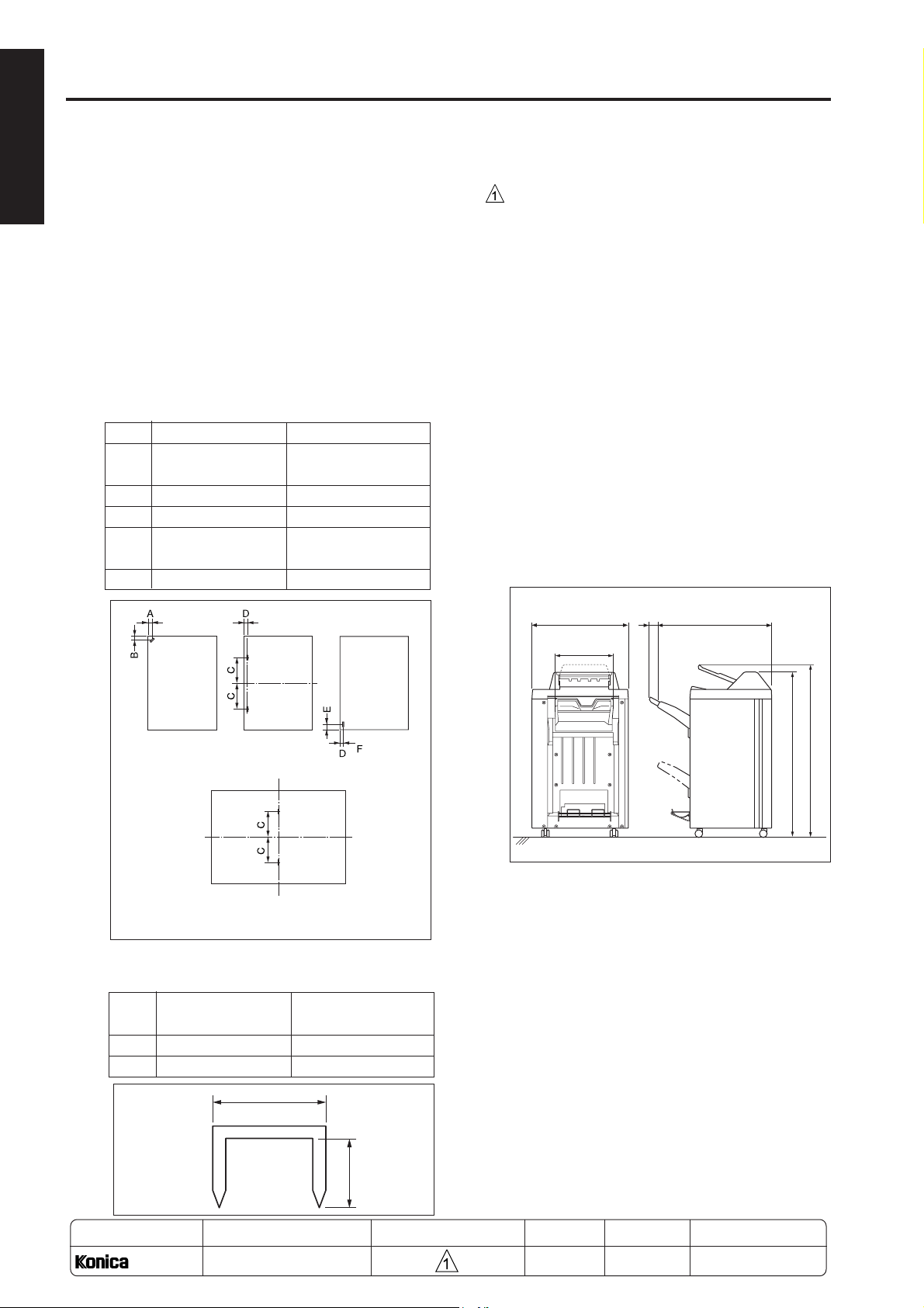
[3] Staple Mode
Number of sheets to be stapled:
FS-111: 50 sheets maximum (the length in the
FS-211: 50 sheets maximum
Staple position:
A 9.0mm±3mm 8.5mm±3mm
B 9.0mm±3mm 8.5mm±3mm
C 82.5mm±3mm 82.5mm±3mm
D 9.0mm±3mm 8.5mm±3mm
E 15.0mm±3mm 14.0mm±3mm
paper feed direction is 400 mm or more)
100 sheets maximum (except for paper
mentioned above in parentheses)
* The height must be 10 mm or less when
using 80g/m2 or 20 lbs quality paper.
* The height must be 5 mm or less when
using 80g/m2 or 20 lbs quality paper.
FS-111 FS-211
(adjustment possible) (adjustment possible)
(adjustment possible) (adjustment possible)
[4] Booklet Mode (FS-211 only)
Stapling-and-fold:
Maximum 20 sheets (80g/m2 or 20 lbs paper)
Maximum 19 sheets (80g/m2 or 20 lbs paper)
+1 sheet (200g/m2 or 45 lbs paper)
Folding:
Maximum 3 sheets (80g/m2 or 20 lbs paper)
[5] Option
PI-108 (Cover sheet feeder)
[6] Machine Data
Power Source:
24 VDC, 5 VDC (supplied from the main body)
Maximum Power
Consumption: 100VA
Weight:
FS-111: Approx. 65kg
FS-211: Approx. 80kg
External Dimensions:
656 85
781
(unit: mm)
Single staple
(rear)
Booklet mode (stitch-and-fold)
Two staples Single
(FS-211 only)
Staple capacity: 5000 staples/cartridge
Binding Staples:
FS-111 FS-211
(Binding staples for 100 sheets) (Binding staples for 50 sheets)
A 13.5mm 12.0mm
B 13.2mm 8.0mm
A
staple
(front)
367
1095
[7] Maintenance
Maintenance: Same as the main body.
Service Life: Same as the main body.
[8] Machine Operating Environment
Temperature: 10 to 30½C (50½F to 86½F)
Humidity: 10 to 80% RH
Note: The information herein may subject to change
for improvement without notice.
1151
MODEL
7075/7085
MANUAL
SERVICE HANDBOOK
B
REVISED EDITION DATE
1 - 2
Apr. 2003
PAGE
1-2
METHOD
REPLACEMENT
Page 13
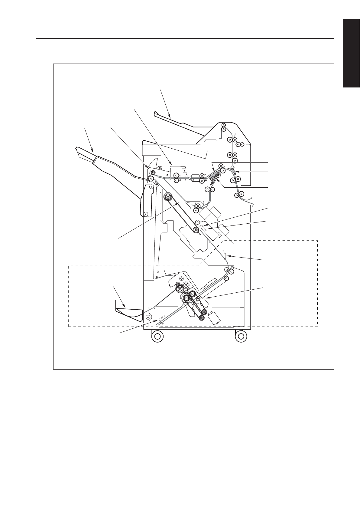
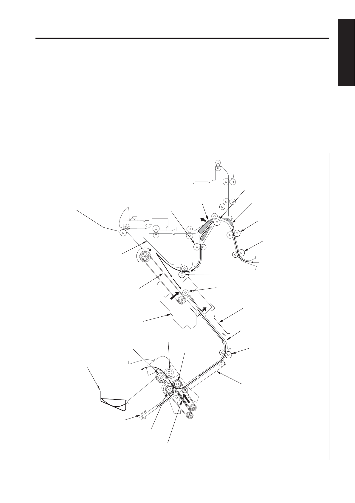
CENTER CROSS-SECTION
Sub-tray
Shift unit
FS-111/FS-211
1 OUTLINE
Main tray
Paper exit unit
Stacker unit
Booklet tray
Gate
Sub-tray gate
By-pass gate
Flat-stapling stopper
Stapler unit
Stapling and
folding stopper
Folding unit
Folding stopper
Area within dotted lines:
FS-211 only
1 - 3
Page 14
FS-111/FS-211
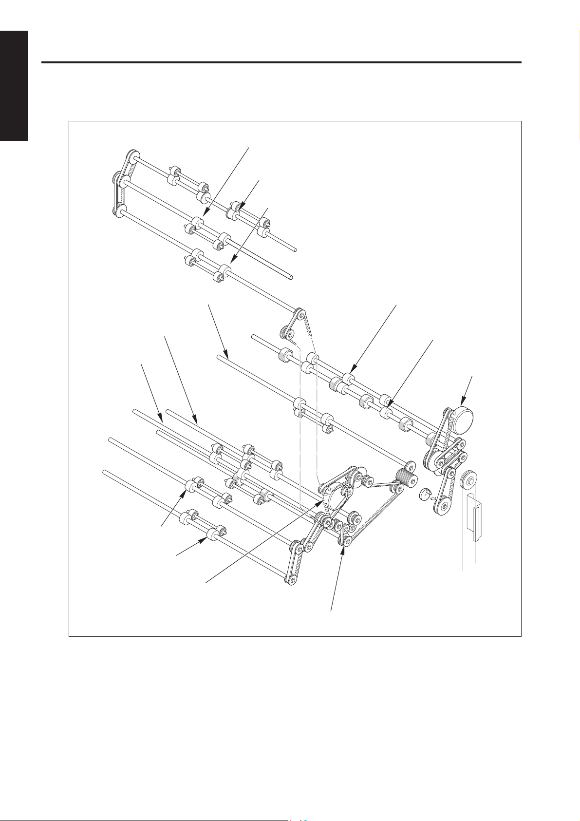
DRIVE SYSTEM DIAGRAM
1 OUTLINE
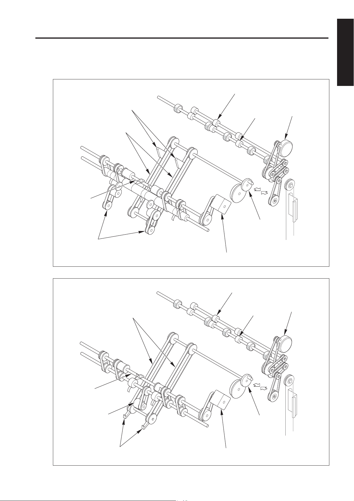
[1] Paper Conveyance Drive
Sub-tray paper exit roller (B)
Sub-tray paper exit roller (C)
Sub-tray paper exit roller (A)
Conveyance slide shaft
Conveyance roller (D)
Conveyance roller (C)
Conveyance roller (B)
Conveyance roller (A)
Nip paper exit roller
Paper exit roller
Paper exit roller
motor (M7)
FNS conveyance motor
(M1)
Intermediate conveyance roller
1 - 4
Page 15
FS-111/FS-211
[2] Stacker Drive
(FS-111)
Stacker entrance
roller
Paper exit arms
Paper exit belts
Nip paper exit roller
Paper exit roller
Coupling
1 OUTLINE
Paper exit roller
motor (M7)
Swivel roller
(FS-211)
Stacker
entrance roller
Paper exit belts
Stacker entrance motor (M13)
Nip paper exit roller
Paper exit roller
Paper exit roller
motor (M7)
Swivel roller
Paper exit arms
Coupling
Stacker entrance motor (M13)
1 - 5
Page 16
FS-111/FS-211
1 OUTLINE
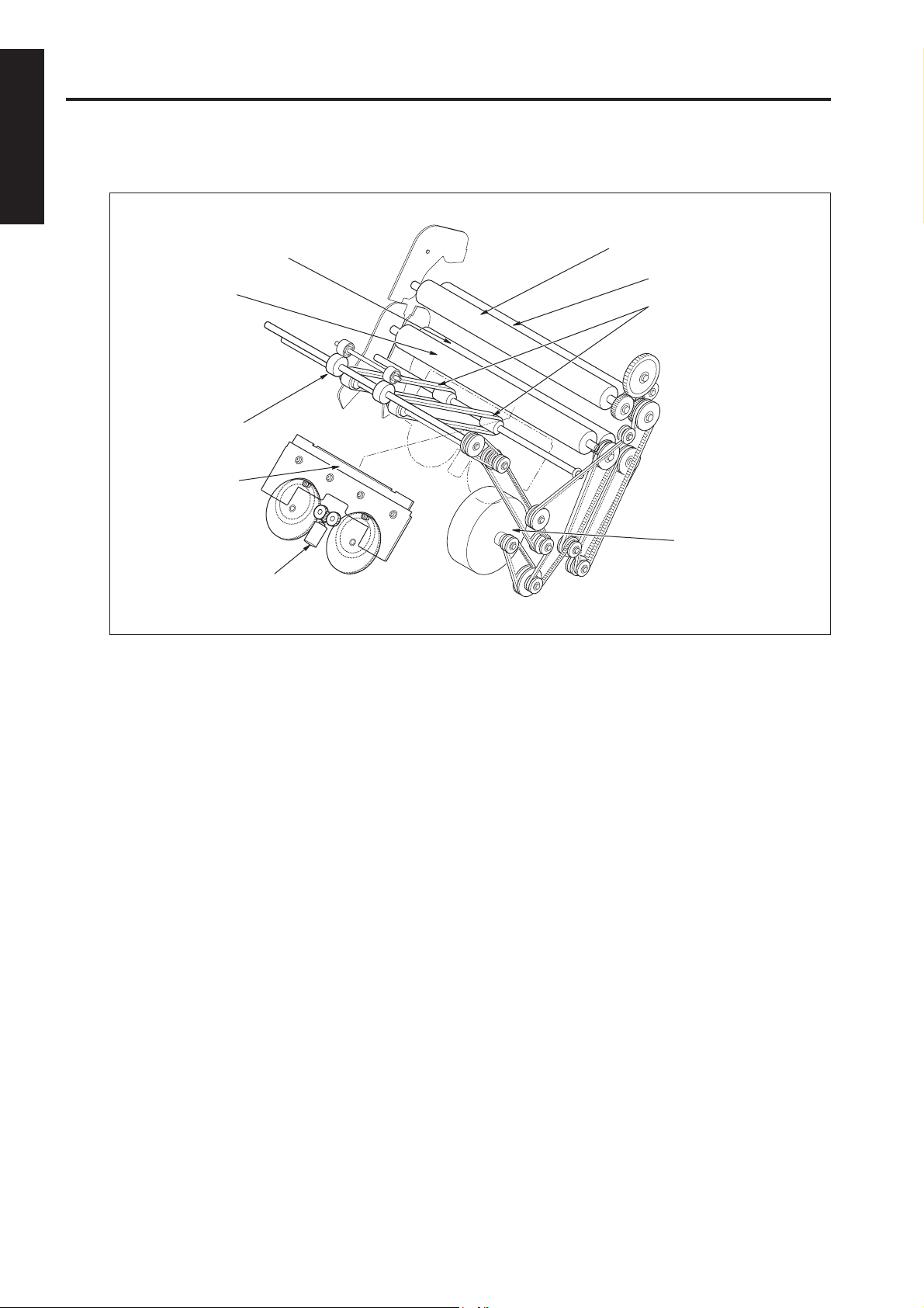
[3] Folding Drive (FS-211 only)
Folding roller (B)
Folding roller (A)
Folding conveyance
roller
Folding knife
Folding knife motor
(M19)
Pressure roller (A)
Pressure roller (B)
Folding conveyancebelts
Folding conveyance
motor (M20)
1 - 6
Page 17
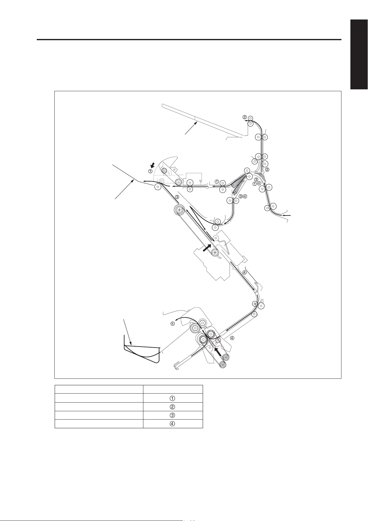
PAPER CONVEYANCE PROCESS
FS-111/FS-211
[1] Paper Conveyance Process
The FNS (finisher) provides four paper paths, as shown in the diagram below.
Face-up and face-down inversion is handled by at the main-body side by the main body’s exit page inverter.
Sub-tray
Main tray
1 OUTLINE
Booklet tray
Finishing mode
Sort, Group, Non-sort mode
Sub-tray mode
Staple mode
Booklet mode (FS-211 only)
Paper Conveyance Paths
1 - 7
Page 18
FS-111/FS-211
1 OUTLINE
[2] Non-Sort Mode
Exit to main tray
A paper exited from the main body is conveyed and exited to the main tray.
Main tray
Sub-tray gate
Gate
Conveyance roller (B)
Conveyance
roller (A)
Paper exit roller
Conveyance roller (D)
Conveyance roller (C)
1 - 8
Page 19
FS-111/FS-211
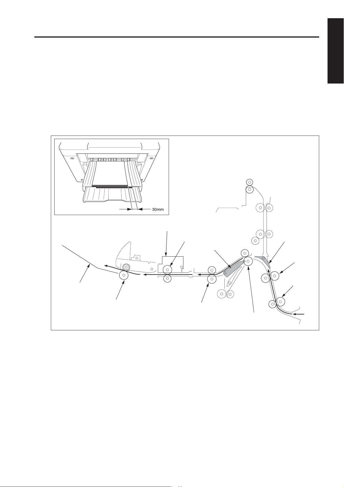
[3] Sort, Group Mode
Exit to main tray
Paper exited from the main body is conveyed and exited to the main tray. This mode has an off-set function
that allows each page of the even-numbered sets to be exited with the paper shifted 30mm to the rear.
Off-set Function
(1) The odd-numbered pages are exited to the main tray with the image side face down.
(2) The even-numbered pages are shifted 30mm to the rear by the conveyance slide shaft of the shift unit and
then exited to the main tray.
Shift unit
1 OUTLINE
Main tray
Paper exit roller
Conveyance slide shaft
Gate
Conveyance roller (D)
Sub-tray gate
Conveyance
roller (B)
Conveyance
roller (A)
Conveyance roller (C)
1 - 9
Page 20
FS-111/FS-211
1 OUTLINE
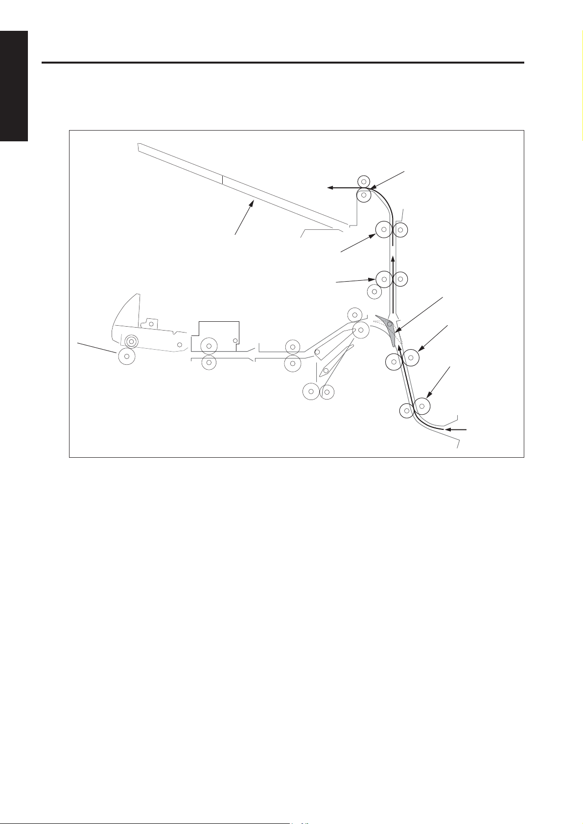
[4] Sub-tray Mode
The sub-tray gate opens. Paper exited from the main body is conveyed and exited to the sub-tray.
Sub-tray paper exit roller (C)
Sub-tray
Sub-tray paper exit roller (B)
Sub-tray paper exit roller (A)
Sub-tray gate
Conveyance roller (B)
Conveyance roller (A)
1 - 10
Page 21
FS-111/FS-211
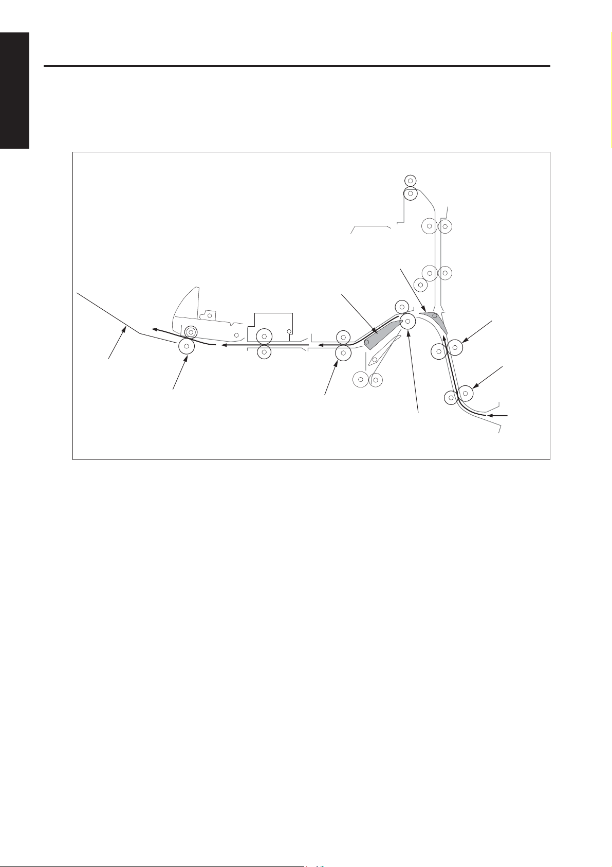
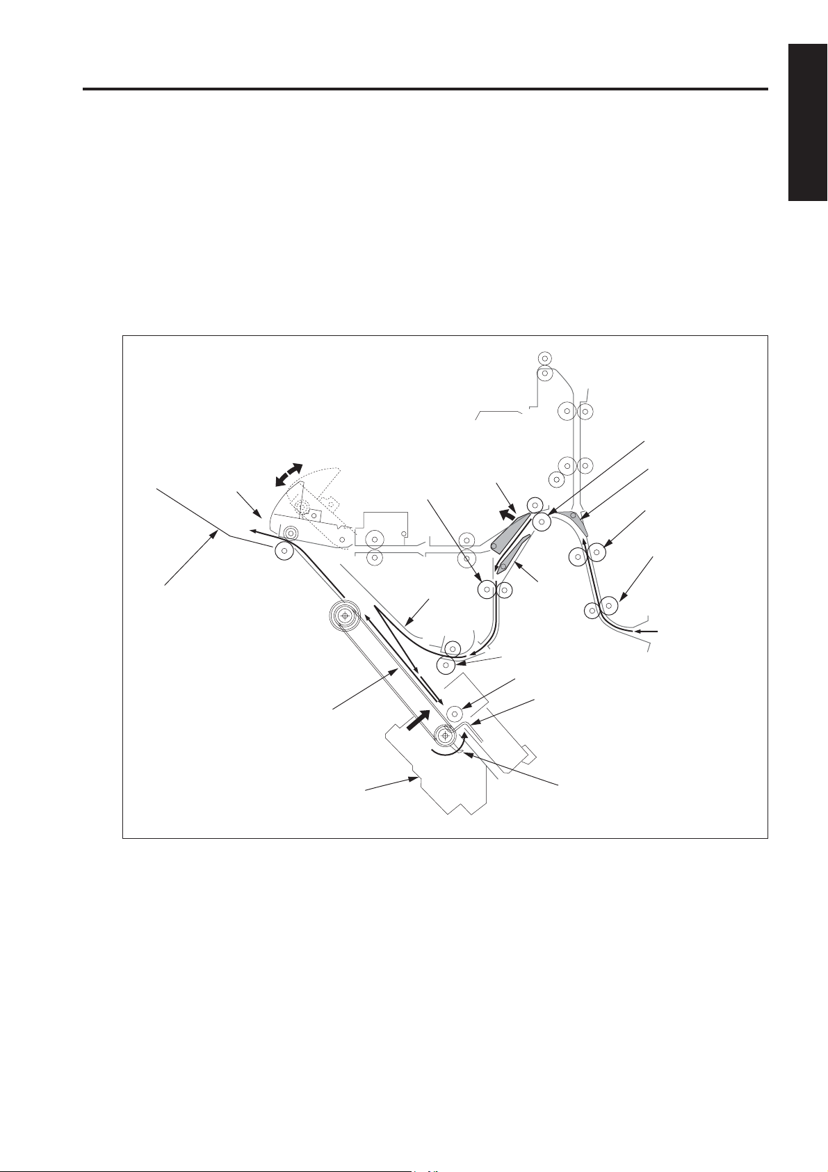
[5] Staple Mode
(1) The gate switches to the staple mode.
(2) For A4R paper and above, the paper exit opening opens.
(3) The first set of paper is conveyed and stacked.
1) The stacker section roller sends the paper to the flat-stapling stopper and the paper is lined up in the
lengthwise direction.
2) The upper alignment plate lines up paper in the widthwise direction.
3) Paper is stapled.
4) The first set is conveyed by the paper exit arm and exited to the main tray.
Conveyance roller (C)
Paper exit
First stapled set
opening
Intermediate
conveyance roller
Gate
Sub-tray gate
Conveyance roller (B)
Conveyance roller (A)
1 OUTLINE
Main tray
Paper exit belt
Stapler unit
Alignment plate
/upper
By-pass
gate
Stacker entrance
roller
Swivel roller
Flat-stapling stopper
Paper exit arm
1 - 11
Page 22
FS-111/FS-211
1 OUTLINE
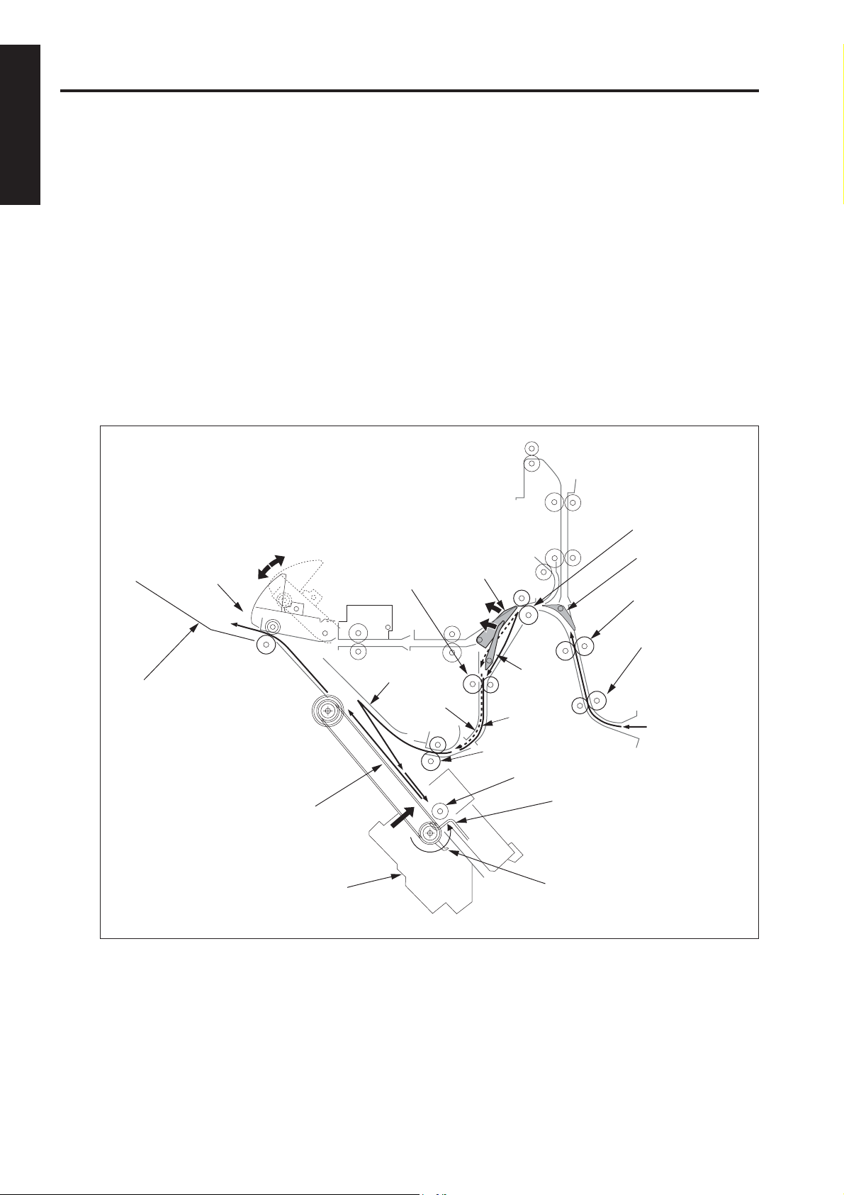
(4) The second and subsequent sets of paper are conveyed and stacked.
1) The first page stops in the stacker entrance with the by-pass gate opened. The stacker entrance
roller stops to wait for the previous stack to be exited.
2) The by-pass gate is closed and the second page is stacked on top of the first.
3) Once the previous stack has exited, the stack entrance roller rotates and the first and second pages
are simultaneously sent to the stacker.
* The above steps (1) to (3) are for paper to a maximum of A4 size.
4) The stacker section roller sends the paper to the flat-stapling stopper and the paper is lined up in
the lengthwise direction.
5) The upper alignment plate lines up paper in the widthwise direction.
6) When all paper is conveyed to the stacker, the paper is stapled.
7) The second and subsequent sets are conveyed by the paper exit arm and the paper is exited to
the main tray.
Paper exit opening
Conveyance roller (C)
Second stapled set
Intermediate
conveyance roller
Gate
Sub-tray gate
Conveyance roller (B)
Main tray
Paper exit belt
Stapler unit
Alignment
plate/upper
Second sheet
Conveyance roller (A)
By-pass
gate
First
sheet
Stacker entrance roller
Swivel roller
Flat-stapling stopper
Paper exit arm
1 - 12
Page 23
FS-111/FS-211
[6] Booklet Mode (FS-211 only)
(1) The gate switches to the staple mode.
(2) The paper exit opening opens.
(3) The paper is conveyed and stacked.
(4) The stacker section roller sends the paper to the stapling-and-folding stopper and the paper is lined up in the
lengthwise direction.
(5) The upper and lower alignment plate lines up paper in the widthwise direction.
(6) If stapling-and-folding has been selected, staple the stack.
(7) Release the stapling-and-folding stopper and convey the stack to the folding unit by the paper exit belt.
(8) Convey the stack up to the folding stopper, fold it with the folding knife, and eject to the booklet tray.
Conveyance roller (C)
Intermediate
conveyance roller
Gate
Sub-tray gate
Conveyance roller (B)
1 OUTLINE
Upper alignment plate
Paper exit belt
Stapler unit
Pressure roller (B)
Booklet tray
Pressure roller (A)
Folding roller (A)
Conveyance roller (A)
Stacker entrance roller
Swivel roller
Alignment plate/lower
Stapling and folding stopper
Folding conveyance roller
Folding conveyance belt
Folding stopper
Folding roller (B)
Folding knife
1 - 13
Page 24

FS-111/FS-211
1 OUTLINE
Blank page
1 - 14
Page 25

2
UNIT EXPLANATION
2 UNIT EXPLANATION
Page 26

2 UNIT EXPLANATION
Blank page
Page 27

EXTERNAL SECTION
[1] Composition
Sub-tray
FS-111/FS-211
Paper exit cover
Top cover
Main tray
Rear cover
Paper exit stopper plate
Booklet tray
(FS-211 only)
[2] Mechanisms
Mechanism
Jam pmrocessing *1
*1 Jam processing
To remove a jamming paper in the convey
ance unit, open the front cover, rotate the con
veyance roller, then open each guide plate.
To remove a jamming paper in the stapler unit,
open the front cover, then pull out the stapler
section.
To remove a jamming paper in the folding unit,
open the front cover, rotate the conveyance roller,
then open the guide plate.
Method
Roller rotation
Guide plate open/close
2 UNIT EXPLANATION
Front cover
Front side cover
Conveyance unit
Stapler unit
Folding unit
2 - 1
Page 28

FS-111/FS-211
CONVEYANCE SECTION
[1] Composition
Sub-tray
paper exit roller (C)
Sub-tray
paper exit roller (B)
Sub-tray
paper exit roller (A)
2 UNIT EXPLANATION
Conveyance roller (B)
Conveyance roller (A)
Conveyance roller (C)
Intermediate
conveyance roller
FS-111/FS-211 Rear View
Deceleration roller
FNS conveyance motor (M1)
Conveyance slide shaft
Paper exit roller motor
(M7)
Nip paper exit roller
Paper exit roller
(Sponge roller)
Conveyance roller (D)
Stacker entrance motor
(M13)
Stacker entrance roller
Paper exit belt
Folding
conveyance roller
Folding conveyance belt
Folding conveyance
motor (M20)
Area within dotted lines: FM-211 only
Folding roller (A)
Pressure roller (A)
Pressure roller (B)
Folding roller (B)
2 - 2
Page 29

FS-111/FS-211
[2] Mechanisms
Mechanism
Paper conveyance
*1
Path switching *2
Shift mechanism of
the shift unit *3
Stacker unit *4
Stapler paper exit
*5
Sub-tray
exit *6
Folding *7
*1 Paper Conveyance
Paper conveyance is carried out by conveyance
rollers (A), (B), (C), and (D); the intermediate conveyance roller; the conveyance slide shaft; and
sub-tray paper exit rollers (A), (B), and (C). These
components are driven by the FNS conveyance
motor (M1) by means of a timing belt.
Stacking is implemented by the stacker entrance
roller and the swivel roller. These rollers are
driven by the stacker entrance motor (M13) by
means of a timing belt.
Method
Motor + roller
Gate /sub-tray
Gate/by-pass
Gate + solenoid
Roller shift
FS-111: Stapler and
clincher combined
FS-211: Stapler and
clincher separated
Paper exit belt + roller
Deceleration roller re
lease
Folding knife
*2 Paper Path Switching
Gate
Sub-tray paper exit
solenoid (SD2)
By-pass
solenoid (SD5)
Sub-tray gate
By-pass gate
Gate solenoid
(SD1)
Path switching is carried out by the gate, the subtray gate, and the by-pass gate. Each of these is
controlled by the ON/OFF action of a corresponding solenoid: the gate solenoid (SD1), the subtray paper exit solenoid (SD2), and the by-pass
solenoid (SD5), respectively.
*3 Shift Unit Sort Shift Operation
(1) Paper entering the shift unit is fed toward the
paper exit direction by the action of the slide
shaft.
(2) Driving by the roller shift motor (M2) causes the
linkage to shift the slide shaft and paper 30mm
toward the rear.
Link mechanism
2 UNIT EXPLANATION
Ejection to the main tray (following staple
processing) is implemented by the stacker paper exit belt arm and the paper exit roller. These
components are driven by the paper exit motor
(M7).
Ejection to the booklet tray is implemented by
the folding conveyance roller, the folding conveyance belt, the folding knife, folding rollers A and
B, and pressure rollers A and B. The folding knife
is driven by the folding knife motor (M19). The
conveyance belt, folding rollers, and pressure
rollers are driven by the folding conveyance motor (M20) by means of a timing belt.
Paper exit
direction
Slide shaft
Roller shift motor
(M2)
Slide shaft
Link mechanism
Roller shift motor
(M2)
30mm towards the direction
of the rear side
2 - 3
Page 30

FS-111/FS-211
*4 Stacker Unit a. Paper Alignment (Staple Mode (Flat Stapling))
Sheets conveyed into the stacker are aligned by
the oscillation of the (front and rear) alignment
plates/upper. The alignment plates/upper are
driven by the alignment plate/upper motor (M5).
b. Paper Alignment (Booklet Mode (FS-211 only))
Sheets conveyed into the stacker are aligned by
the movement of the (front and rear) alignment
Alignment
plate/
2 UNIT EXPLANATION
upper
Paper exit
belts
Paper exit arms
Paper exit
belts
Alignment
plate/upper
motor
(M5)
Alignment plate/
upper
plates/upper and the (front and rear) alignment
plates/lower. The alignment plates/upper are
driven by the alignment plate motor/upper (M5);
the alignment plates/lower are driven by the alignment plate motor/lower (M15). The stapling-andfolding stopper is moved by the stapling-and-folding stopper motor (M14) and is released by the
stapling-and-folding stopper release motor (M17).
Stapling and
folding stopper
release motor
(M17)
Stapling and folding stopper
Alignment plate/lower
FS-211 Only
Stapling and folding
stopper motor (M14)
Alignment
plate/lower
Alignment plate motor/lower
(M15)
c. Paper Exiting to the main tray
Stapled paper is sent to the paper exit by the
paper exit arm. The paper exit belt is driven by
the paper exit-roller motor (M7).
d. Feeding to the Folding Unit (FS-211 only)
The stapling-and-folding stopper release motor
(M17) releases the stapling-and-folding stopper
and feeds the paper into the folding unit.
2 - 4
Page 31

FS-111/FS-211
*5 Paper Exit Opening Unit c. Pressure of the Paper Exit Roller
The paper exit roller turns more slowly than the
Paper exit opening solenoid
(SD4)
Paper exit opening
Nip roller
Paper exit opening
motor (M8)
conveyance rollers (A, B, C, and D), and remains
unengaged by the nip roller except during ejection.
When paper reaches the paper exit opening, the
paper exit roller is engaged by the nip roller and
the paper is ejected to the main tray. Engagement and release is controlled by the paper exit
opening solenoid (SD4).
a. Staple Mode and Booklet Mode Operation for
Paper Sizes A4R and Above
Because paper of this size juts out from the
stacker, the paper exit opening is held open from
the start of copying until the completion of stapling.
b. Paper Exit of the Staple Mode (Flat Stapling)
Upon completion of stapling, the paperr exit
closes, and the paper is grasped and ejected to
the main tray. The opening and closing of the
paper exit is controlled by the paper exit opening
motor (M8).
Paper exit opening motor
(M8)Paper exit opening
Open
Close
Paper exit opening
solenoid (SD4)
Paper exit opening
Main tray
Paper
exit roller
Conveyance
roller (D)
Conveyance
roller (B)
Conveyance roller (C)
Conveyance roller (A)
Nip roller
2 UNIT EXPLANATION
2 - 5
Paper exit roller
Paper exit opening solenoid
(SD4)
Page 32

FS-111/FS-211
*6 Sub-tray
Exit paper is conveyed to the sub-tray via the subtray paper exit rollers (A), (B) and (C) during the
sub-tray mode. In this mode, the deceleration
roller lowers when the sub-tray deceleration solenoid (SD6) turns ON; then the paper is nipped
between the sub-tray deceleration solenoid and
the sub-tray paper exit roller (C) rotating at a low
speed, and the conveyance speed of the exiting
paper decelerates.
2 UNIT EXPLANATION
Sub-tray deceleration solenoid (SD6)
Deceleration roller
*7 Folding by the Folding Unit (FS-211 only)
Paper is conveyed to the folding stopper by the
action of the folding conveyance roller and the
folding conveyance belts, and is then folded by
the action of the folding knife and the folding rollers. The folding conveyance roller, the folding
conveyance belts, the folding rollers, and the
pressure roller are driven by the folding conveyance motor (M20). The folding stopper motor
(M18) drives the folding stopper. The folding knife
motor (M19) drives the folding knife.
Folding conveyance
motor (M20)
Folding rollers
Folding stopper
motor (M18)
Folding paper-end
stopper
Folding knife
Folding
conveyance belts
Folding knife
2 - 6
Folding knife
Paper
Folding knife motor
(M19)
Page 33

FS-111/FS-211
[3] M1 (FNS Conveyance) Control
MS1
SGND
PGND
PGND
MAIN BODY
24V
24V-IN
5V
M_TXD
SGND
M_REQ
SGND
M_ACK
SGND
M_RXD
SGND
S_REQ
SGND
S_ACK
SGND
FNS CB
M1 (FNS conveyance) drives paper conveyance (if
main-tray exit) and paper exit (if sub-tray exit) by means
of conveyance rollers (A), (B), (C), (D), conveyance
slide shaft and the sub-tray paper paper exit roller (A),
(B), (C). M1 is controlled by the FNS CB (FNS control
board).
H/L
CONT
CLK
F/R
24V
24V
PGND
PGND
GND
GND
24V
DRV
GND
5V
LD
5V
IN
5V
IN
5V
IN
M1
PS1
PS4
SD6
PS207
1. Operation
a. Interlock
FNS paper-conveyance drive control is initiated
by the ON signal from the main body START
button. If MS1 (interlock) is OFF at this time, however, the finisher transmits an error signal to the
main body CB and does not begin control.
b. PS207 (paper exit cover open/close detection)
control
As mentioned above, FNS paper-conveyance
drive control is initiated by the ON signal from
the main body START button. But if PS207 (paper exit cover open/close detector) is [H] at this
time (paper exit cover is open), the FNS transmits an error signal to the main body CB and
does not begin control.
c. M1 (FNS conveyance) control
(1) Main tray paper exit operation
M1 is set ON by the ON signal of the START
button and goes OFF a preset time interval after
PS4 (FIN entrance passage) detects the trailing
edge of the final copy paper.
(2) Sub-tray paper exit operation
SD6 (sub-tray deceleration) turns ON a predefined time after PS4 detects the trailing edge of
the paper, and the deceleration roller is stuck with
pressure to the sub-tray exit roller (C). Thus the
speed of ejecting paper is reduced.
SD6 then turns OFF a predefined time after PS1
(sub-tray paper exit) detects the trailing edge of
the paper.
2 UNIT EXPLANATION
2 - 7
Deceleration roller
Sub-tray
paper exit roller (B)
Sub-tray
M1 (FNS conveyance)
Sub-tray paper
exit roller (A)
Sub-tray paper exit
roller (C)
PS1 (Sub-tray
paper exit)
Sub-tray
Conveyance
roller (B)
PS4
(FNS
entrance
passage)
Conveyance roller (A)
Page 34

FS-111/FS-211
2. Signals
a. Input signals
(1) TXD (Main body CB to FNS CB)
Serial data line; transmits operating status of the
main body’s CB to the FNS CB.
(2) DTR (Main body CB to FNS CB)
Request to send signal from the main body to the
FNS.
(3) RTS (Main body CB to FNS CB)
Transmission acknowledgment signal from the
main body to the FNS.
2 UNIT EXPLANATION
(4) 24V IN (MS1 to FNS CB)
Outputs +24V if MS1 (interlock) is ON. The power
is supplied to all loads on the FNS side.
(5) PS207 IN (PS207 to FNS CB)
Inputs [L] when the sub-tray paper paper exit
cover is closed.
(6) PS4 IN (PS4 to FNS CB)
Comes ON and inputs [L] when paper passes
through the FNS inlet.
(7) M1PLL (M1 to FNS CB)
Monitors rotation status of M1 (FNS conveyance).
[L] is input when M1 reaches the specified speed.
(8) IN (PS1 to FNS CB)
Turns ON when the paper passes through the
paper exit opening of the sub-tray, and inputs [L].
b. Output signals
(1) TXD (FNS CB to Main body CB)
Serial data line; transmits FNS operating status
to the main body’s CB.
(2) RTS (FNS CB to Main body CB)
Request to send signal from the FNS to the main
body.
(3) DTR (FNS CB to Main body CB)
Transmission acknowledgment signal from the
FNS to the main body.
(4) M1 CONT (FNS CB to M1)
M1 drive control signal.
[H]: OFF
[L]: ON
(5) M1 BRK (FNS CB to M1)
Rotation speed control gain switching signal of
M1.
[H]: High speed rotation
[L]: Low speed rotation
(6) M1 CLK (FNS CB to M1)
Reference clock signal for controlling the speed
of M1.
(7) M1 F/R (FNS CB to M1)
M1 direction signal.
[H]: Clockwise
[L]: Counterclockwise
(8) DRV (FNS CB to SD6)
Drive signal of SD6 (sub-tray deceleration).
[H]: OFF
[L]: ON
2 - 8
Page 35

FS-111/FS-211
[4] Gate Control
DRV
24V
DRV
MS1
SGND
PGND
PGND
MAIN BODY
24V
24V-IN
5V
M_TXD
SGND
M_REQ
SGND
M_ACK
SGND
M_RXD
SGND
S_REQ
SGND
S_ACK
SGND
FNS CB
24V
DRV
24V
GND
GND
GND
GND
5V
IN
5V
IN
5V
IN
5V
IN
The paper conveyance path is switched by the ON/
OFF switching of SD1 (gate), SD2 (sub-tray paper
exit), and SD5 (by-pass), which are switched ON/OFF
by the FNS CB (FNS control board).
SD1
SD2
SD5
PS4
PS5
PS6
PS50
1. Operation
PS5 (Stacker conveyance
passage)
PS50
(Sub-tray
full)
PS6 (Paper
exit 1)
SD1
(Gate)
a. Main-tray Paper Exit Operation (Sort, Group,
and Non-Sort modes)
Paper moves through the shift unit and paper
exits to the main tray, passing through the subtray gate and the gate. As both these gates direct the paper toward the shift-unit side by default, SD2 and SD1 remain OFF.
b. Stacker conveyance operation (Staple mode)
Paper moves through the stacker unit to the main
tray, passing the sub-tray gate, the gate, and the
by-pass gate. As the sub-tray gate is already set
to the stacker side, SD2 remains OFF.
(1) ON timing for SD1
SD1 comes on when the START button ON
signal is received, setting the gate to the stacker
side. The FNS stands by for paper conveyance to
begin.
(2) Conveyance of paper sizes other than A4 and B5
The gates direct the paper into the stacker. SD5
remains OFF, as paper moves without by-pass
toward the stacker entrance roller.
(3) Conveyance of A4 and B5 paper (first paper of
second and subsequent sets)
SD5 comes ON a preset time period after PS4
(FNS entrance passage) detects the trailing edge
of the final paper of the preceding set. This
switches the by-pass gate to the by-pass side, so
that the first paper of the new set is carried to that
side.
PS1 (Sub-tray
paper exit)
SD2
(Sub-tray
paper exit)
PS4
(FNS ent-
rance
passage)
SD5
(By-pass)
Stacker
entrance roller
2 UNIT EXPLANATION
2 - 9
Page 36

FS-111/FS-211
(4) Conveyance of A4 and B5 paper (second and
subsequent papers of second and subsequent
sets)
SD5 turns OFF a preset time period after PS4
(FNS entrance passage) detects the trailing edge
of the first sheet of the current set, closing the bypass gate. The second sheet moves directly
(without by-pass), together with the first paper, to
the stacker entrance roller.
SD5 remains off for the third and subsequent
sheets of the set, which move without by-pass to
2 UNIT EXPLANATION
the stacker.
(5) OFF timing for SD1 (gate)
SD1 turns OFF a preset time period after PS6
(paper exit-1) detects the final stapled set.
c. Stacker conveyance operation (Booklet mode)
(FS-211 only)
Paper moves through the stacker unit to the folding unit, passing the sub-tray gate, the gate, and
the by-pass gate. As the sub-tray gate is already
set to the stacker side, SD2 (sub-tray paper exit)
remains off.
(1) ON timing for SD1
SD1 turns ON when the START button ON signal
is received, setting the gate to the stacker side.
The FNS stands by for paper conveyance to
begin.
(2) The gates direct the paper to the stacker. SD5
remains OFF, as paper moves without by-pass
toward the stacker entrance roller.
(3) OFF timing for SD1
SD1 turns OFF a preset time period after PS6
detects the final stapled set.
d. Sub-tray paper exit operation
SD2 turns ON when the START button ON signal is received, setting the sub-tray gate to the
sub-tray side. SD2 turns OFF a preset time period after PS4 detects the final sheet.
e. Sub-tray full detection
When the papers ejected to sub-tray reach to
specified height, PS50 (sub-tray full) turns ON,
and FNS transmits "sub-tray full" signal to the
main body.
When the main body receives it, the message is
displayed on the operation panel.
Finishing
Sort, Group, and Non-Sort modes
Staple mode, sizes A4,
B5
( ) is for sizes other
than A4, B5
Booklet mode (FS-211 only)
Sub-tray mode
First paper of
2nd or
subsequent set
Others
SD1
OFF
ON
ON
ON
OFF
SD2
OFF
OFF
OFF
OFF
ON
SD5
OFF
ON
(OFF)
OFF
OFF
OFF
2 - 10
Page 37

2. Signals
a. Input signals
(1) PS5 IN (PS5 to FNS CB)
Turns ON ([L]) when paper passage is detected
at the stacker entrance.
(2) PS6 IN (PS6 to FNS CB)
Turns ON ([L]) when paper passage is detected
at the main-tray paper paper exit.
(3) IN (PS50 to FNS CB)
Turns ON ([L]) when sub-tray full is detected.
b. Output signals
(1) SD1 DRV (FNS CB to SD1)
SD1 drive control signal.
[H]: OFF
[L]: ON
(2) SD2 DRV (FNS CB to SD2)
SD2 drive control signal.
[H]: OFF
[L]: ON
(3) SD5 DRV (FNS CB to SD5)
SD5 drive control signal.
[H]: OFF
[L]: ON
FS-111/FS-211
2 UNIT EXPLANATION
2 - 11
Page 38

FS-111/FS-211
[5] M13 (Stacker Entrance) Control
24V
DRVA
DRVA
DRVB
DRVB
24V
M13
2 UNIT EXPLANATION
RB
FS-211 only
M13 (stacker entrance) drives the stacker entrance
roller and the swivel roller, thereby carrying out the
following functions: conveyance of paper to the
stacker; paper alignment; and adjustment of staple
waiting time. M13 is controlled by the FNS CB (FNS
control board) via the RB (relay board)(FS-211) or
directly (FS-111).
MS1
SGND
PGND
PGND
MAIN BODY
24V
M13 DRVA
M13 DRVA
M13 DRVB
M13 DRVB
24V
24V
24V-IN
5V
M_TXD
SGND
M_REQ
SGND
M_ACK
SGND
M_RXD
SGND
S_REQ
SGND
S_ACK
SGND
1. Operation
5V
FNS CB
GND
GND
24V
DRVA
DRVA
DRVB
DRVB
24V
IN
5V
IN
PS4
PS5
M13
FS-111 only
Conveyance to the stacker varies according to
paper size: one method is used for A4 and B5,
another is used for all other sizes.
PS4
(FNS entrance passage)
PS5 (Stacker conveyance
passage)
2 - 12
PS6 (Paper exit 1)
M13 (Stacker
entrance)
Flat-stapling stopper
Stapling and
folding stopper
Stacker
entrance roller
Swivel roller
Page 39

FS-111/FS-211
a. Conveyance to the stacker (sizes other than
A4 or B5)
(1) M13 (stacker entrance) ON timing
M13 is turned ON by the START button ON
signal, and begins with high speed rotation. M13
then switches to low speed rotation a preset time
period after PS5 (stacker conveyance passage)
detects the trailing edge of the paper.
M13 then returns to high speed rotation a preset
period after PS5 detects the trailing edge of the
paper. This action is repeated as necessary to
transport all papers to be stacked into the stacker.
(2) M13 OFF timing
M13 goes OFF a preset time period after PS5
detects the trailing edge of the final paper set.
b. Conveyance to the stacker (A4 and B5 sizes)
(1) First set
Paper for the first set to be stapled is conveyed in
the same way as other paper sizes.
(2) First paper of second and subsequent sets
M13 turns OFF a preset time period after PS4
(FNS entrance passage) detects the trailing edge
of the first paper for the second or subsequent
set, and the paper moves into the by-pass. This
prevents paper from moving into the stacker
while stapling of the previous set is still in progress.
(3) Second and subsequent papers of second and
subsequent sets
M13 resumes low speed rotation a preset time
period after PS4 detects the trailing edge of the
second paper of the set. This causes the first and
second papers to move together (one atop the
other) into the stacker. M13 switches to rapid
rotation a preset time period after PS5 detects the
trailing edge of the first and second papers, so
that it is ready to handle the third paper of the set
when it arrives from the main body. Third and
subsequent papers for the set are then conveyed
in the same way as the papers in the first set.
c. Paper alignment (trailing-edge alignment)
For operation in staple mode:
The swivel roller adjusts the position of each
paper (one paper at a time) within the stacker.
For operation in booklet mode (FS-211 only): The
stapling & folding stopper is moved and set into
appropriate position. The swivel roller adjusts the
position of each paper (one paper at a time).
2. Signals
a. Output signals
(1) DRV A, A, B, B (FNS CB to M13:FS-111)
(FNS CB to RB to M13:FS-211)
M13 drive signal.
2 UNIT EXPLANATION
2 - 13
Page 40

FS-111/FS-211
[6] M5 (Alignment Plate/Upper) Control
PS 8IN
5V
IN
GND
24V
24V
DRVA
2 UNIT EXPLANATION
DRVA
DRVB
DRVB
FS-211
M5 (alignment plate/upper) aligns the paper widthwise
in the stacker by opening and closing the alignment
plates/upper. M5 is controlled by the FNS CB (FNS
control board) via the RB (relay board)(FS-211) or
directly (FS-111).
M5
PS8
PS5
MS1
24V
5V
SGND
PGND
PGND
MAIN BODYRB
M5 DRVA
M5 DRVA
M5 DRVB
M5 DRVB
5V
IN
GND
5V
IN
GND
24V
24V
DRVA
DRVA
DRVB
DRVB
24V-IN
M_TXD
SGND
M_REQ
SGND
M_ACK
SGND
M_RXD
SGND
S_REQ
SGND
S_ACK
SGND
FNS CB
Alignment
plate/upper
PS5
(Stacker
conveyance
passage)
FS-111
M5 (Alignment plate/upper)
2. Signals
a. Input signals
(1) IN (PS8 to FNS CB:FS-111)
(PS8 to RB to FNS CB:FS-211)
Detects signal of the alignment plate/upper HP.
[L] indicates the alignment plate/upper is at HP.
b. Output signals
(1) DRV A ,A, B, B (FNS CB to M5:FS-111)
(FNS CB to RB to M5:FS-211)
M5 drive signals.
1. Operation
At initial operation, the alignment plates/upper are
stationary at the ON position of PS8 (alignmentplate/upper HP).
A specified time period after PS5 (stacker conveyance passage) detects the paper trailing edge,
M5 begins rotation so as to close the plates. After another specified interval it opens the plates.
This cycle repeats for each paper.
2 - 14
Page 41

[7] M15 (Alignment Plate/Lower) Control (FS-211 only)
FS-111/FS-211
5V
PS24
M15
PS24IN
GND
24V
24V
DRVA
DRVA
DRVB
DRVB
PS24IN
M15 (alignment plate/lower) aligns the stapling-andfolding position by opening and closing the alignment
plates/lower.
M15 is controlled by the FNS CB (FNS control board)
via the RB (relay board).
1. Operation
At start-up, the alignment plates/lower are stationary at the ON position of PS24 (alignmentplate/lower HP). A specified time period after PS5
(stacker conveyance passage) detects the paper trailing edge, M15 begins rotation so as to
close the plates. After another specified interval
it opens the plates. This cycle repeats for each
paper.
M15 DRVA
MS1
SGND
PGND
PGND
MAIN BODY
24V
M15 DRVA
M15 DRVB
M15 DRVB
24V-IN
5V
5V
SGND
PGND
PGND
M_TXD
SGND
M_REQ
SGND
M_ACK
SGND
M_RXD
SGND
S_REQ
SGND
S_ACK
SGND
FNS CBRB
GND
Alignment
plate/upper
M5
(Alignment
plate/upper)
M15
(Alignment plate/lower)
2. Signals
a. Input signals
(1) PS24 IN (PS24 to RB to FNS CB)
Detects signal of the alignment plate/lower HP.
[L] indicates the alignment plate/lower is at HP.
b. Output signals
(1) DRV A, A, B, B (FNS CB to RB to M15)
M15 drive signals.
5V
IN
PS5
2 UNIT EXPLANATION
PS5
(Stacker
conveyance
passage)
Alignment
plate/lower
2 - 15
Page 42

FS-111/FS-211
[8] M2 (Roller Shift) Control
24V
24V-IN
5V
M_TXD
SGND
M_REQ
SGND
M_ACK
SGND
M_RXD
SGND
S_REQ
SGND
S_ACK
SGND
FNS CB
MS1
SGND
PGND
PGND
2 UNIT EXPLANATION
MAIN BODY
When running in Sort or Group mode, the FNS carries
out shifting of paper. Shifting is driven by M2 (roller
shift), which is controlled by the FNS CB (FNS control
board).
1. Operation
If operation is in sort or group mode, M2 (roller
shift) turns ON a predetermined time period after PS4 (FNS entrance passage) detects the trailing edge of a paper that needs to be shifted.
Rotation of M2 starts shifting of the conveyance
slide shaft, while rotation of M1 (FNS conveyance) causes the shaft to turn, so that shifting
and conveyance occur simultaneously.
PS18 (roller-shift HP) turns ON when the conveyance slide shaft has been fully shifted, causing M2 to turn OFF.
A specified time period after PS4 turns OFF, M2
turns ON and returns the conveyance slide shaft
to its original position. PS18 turns OFF when the
conveyance slide shaft has returned all the way,
causing M2 to turn OFF again.
This operation is repeated as necessary to shift
paper as it moves toward the exit roller.
24V
DRV
GND
GND
5V
IN
5V
IN
M2
PS4
PS18
M2 (Roller shift)
Conveyance
slide shaft
Paper exit roller
2. Signals
a. Input signals
(1) IN (PS18 to FNS CB)
Detect signal of roller shift position.
[L] to [H]: Front position
[H] to [L]: Rear position
b. Output signals
(1) DRV (FNS CB to M2)
M2 drive signal.
[H]: ON
[L]: OFF
PS18 (Roller
shift HP)
PS4
(FNS
entrance
passage)
2 - 16
Page 43

[9] M7 (Paper Exit Roller) Control
FS-111/FS-211
PS9IN
5V
GND
IN
FS-211
PS9
MS1
MAIN BODY
FS-111
24V
SGND
PGND
PGND
5V
The paper exit belt ejects paper from the stacker, while
the paper exit roller ejects the paper from the FNS to
the main tray. M7 (paper exit roller) drives both the
belt and the roller. M7 is controlled by the FNS CB
(FNS control board) via RB (Relay board)(FS-211) or
directly (FS-111).
1. Operation
a. Sort, Group, and Non-Sort modes
M7 starts turning when PS4 (FNS entrance passage) detects the leading edge of a paper.
M7 turns OFF when PS10 (paper exit 2) detects
paper exit of the paper, unless an FNS start signal has already been received from the main
body.
5V
IN
SGND
24V-IN
M_TXD
SGND
M_REQ
SGND
M_ACK
SGND
M_RXD
SGND
S_REQ
SGND
S_ACK
SGND
PS6 (Paper exit 1)
Paper exit
roller
(Sponge roller)
5V
P/S
CLK
H/L
LD
PGND
PGND
24V
24V
F/R
5V
IN
GND
5V
IN
GND
FNS CBRB
M7
PS4
2 UNIT EXPLANATION
PS10
M7
(Paper exit roller)
PS10 (Paper exit 2)
PS9 (Paper exit belt HP)
Paper exit belt
Paper exit
arm
b. Staple mode (flat stapling)
M7 starts rotating when stapling is finished, and
stops when PS9 (paper exit-belt HP) turns ON.
c. Booklet mode
M7 starts rotating in reverse when stapling is finished, and stops when PS9 turns ON.
2 - 17
Page 44

FS-111/FS-211
2. Signals
a. Input signals
(1) IN (PS9 to FNS CB : FS-111)
(PS9 to RB to FNS : FS-211)
Turns ON ([L]) when the paper exit belt is in HP.
(2) IN (PS10 to FNS CB)
Turns ON ( [L]) when paper passage is detected
at the FNS paper exit.
(3) LD (M7 to FNS CB)
M7 (Paper exit roller) rotational status detection
signal. This signal becomes [L] when M7 reaches
2 UNIT EXPLANATION
the specified speed.
b. Output signals
(1) P/S (FNS CB to M7)
M7 drive control signal.
[H]: OFF
[L]: ON
(2) CLK (FNS CB to M7)
M7 rotating speed control clock signal.
(3) H/L (FNS CB to M7)
M7 rotating speed control gain switching signal.
[H]: low speed
[L]: High speed
(4) F/R (FNS CB to M7)
M7 rotation direction control signal.
[H]: Counterclockwise
[L]: Clockwise
2 - 18
Page 45

FS-111/FS-211
[10] SD4 (Paper Exit Opening) Control
5V
IN
FNS CB
GND
GND
GND
5V
IN
5V
IN
SD4
MS1
SGND
PGND
PGND
MAIN BODY
24V
DRV
24V
24V-IN
5V
M_TXD
SGND
M_REQ
SGND
M_ACK
SGND
M_RXD
SGND
S_REQ
SGND
S_ACK
SGND
SD4 (paper exit opening) controls engagement by the
nip paper exit roller. SD4 is controlled by the FNS CB
(FNS control board).
1. Operation
When ejection is not in progress, a gap is maintained between the nip paper exit roller and the
paper exit roller so as to prevent paper jams at
the paper exit.
At time of ejection, however, SD4 turns ON, inclining the nip paper exit roller against the paper
exit roller so that the gap is closed.
a. SD4 ON timing
(1) Sort, Group, and Non-Sort modes
SD4 turns ON a preset time period after PS10
(paper exit 2) detects the leading edge of the
paper.
(2) Staple mode
SD4 turns ON a preset time period after completion of stapling.
PS6
PS10
PS12
b. SD4 OFF timing
(1) Sort, Group, and Non-Sort modes
SD4 turns OFF a preset time period after PS10
detects the trailing edge of the paper.
(2) Staple mode
SD4 turns OFF a preset time period after PS6
(paper exit 1) detects the trailing edge of the
paper set.
Conveyance roller (B)
PS6 (Paper exit 1)
Nip paper
exit roller
SD4
(Paper exit
opening)
PS10 (Paper
Conveyance
roller (C)
exit 2)
Conveyance roller (D)
Paper exit roller
(Sponge roller)
PS4 (FNS entrance
passage)
Conveyance roller (A)
2. Signals
a. Input signals
(1) PS12 IN (PS12 to FNS CB)
Detects open/closed state of the paper exit opening.
[H] ∅ [L]: Closed
[L] ∅ [H]: Open
b. Output signals
(1) SD4 DRV (FNS CB to SD4)
SD4 (paper exit opening) drive control signal.
[H]: OFF
[L]: ON
2 UNIT EXPLANATION
2 - 19
Page 46

FS-111/FS-211
[11] M8 (Paper Exit Opening) Control
24V
24V-IN
5V
M_TXD
SGND
M_REQ
SGND
M_ACK
SGND
M_RXD
SGND
S_REQ
SGND
S_ACK
SGND
FNS CB
MS1
SGND
PGND
PGND
2 UNIT EXPLANATION
MAIN BODY
M8 (paper exit opening) opens and closes the paper
exit by means of a linkage mechanism. M8 is controlled
by the FNS CB (FNS control board).
1. Operation
If large paper (the length in the paper feed
direction is 217 mm or more) is being stapled,
M8 turns ON when the START button ON signal
is received, causing the paper exit to open.
Upon completion of stapling, the stapling-completed signal from the FNS CB causes the paper
exit to close, and the stapled set is exited.
The status of the paper exit opening is detected
by PS12 (paper exit opening).
24V
DRV
GND
5V
IN
M8
PS12
When print
starts
When paper conveying to stacker
When paper
exit to the main
tray
Staple
(large paper)
Staple
(small paper)
Off-set
Booklet
Open
Closed
Closed
Open
Open
Closed
Open
2. Signals
a. Input signals
(1) PS12 IN (PS12 to FNS CB)
Detects open/closed state of the paper exit opening.
[H] to [L]: Closed
[L] to [H]: Open
b. Output signals
(1) M8 DRV (FNS CB to M8)
M8 drive control signal.
[H]: ON
[L]: OFF
Closed
Closed
Closed
Open
Paper exit
M8 (Paper exit opening)
PS12
(Paper exit
opening)
2 - 20
Page 47

STAPLER UNIT
[1] Composition
Stapler (F)
FS-111/FS-211
FS-111
Stapler movement motor (M11)
Flat-stapling stopper
Stapling and folding
stopper HP PS (PS23)
Stapling and
folding stopper
motor (M14)
Clincher (F)
Flatstapling stopper
Stapling and
folding stopper
release motor
(M17)
Stapler (R)
2 UNIT EXPLANATION
Stapler rotation motor (M4)
FS-211
Stapler movement motor (M11)
Cincher (R)
Flat-stapling stopper
Stapler rotation motor (M4)
Stapling and folding stopper
Stapler (R)
Stapler rotation HP PS (PS14)
2 - 21
Stapler movement
HP PS (PS11)
Stapler (F)
Page 48

FS-111/FS-211
[2] Mechanisms
Mechanism
Staple mode *1
Stopper *2
2 UNIT EXPLANATION
(FS-211 only)
Stapling operation
*3
Method
FS-111:
Single staple (front/rear)
Two staples (flat)
FS-211:
Single staple (front/rear)
Two staples (flat)
Two staples (stapling and
folding)
Flat-stapling stopper
Staple-and-folding stopper
FS-111:
Stapler and clincher
combined
FS-211:
Stapler and clincher
separated
*1 Staple mode
a. Single staple (front or rear)
The stapler movement motor (M11) moves only
the stapler (F and R)(FS-111) or both the stapler
(F and R) and clincher (F and R)(FS-211) to the
stapling position.
When the stapling position is at the back, the stapler rotation motor (M4) rotates only the stapler
(R)(FS-111) or both the stapler (R) and clincher
(R)(FS-211) to the stapling position.
Only the stapler (FS-111) or both the stapler and
clincher (FS-211) staple the paper aligned by the
stacker.
FS-111
Stapler rotation motor (M4)
Stapler movement motor (M11)
Stapler movement motor
(M11)
Stapler rotation motor (M4)
FS-211
2 - 22
Page 49

FS-111/FS-211
b. Tow staples (flat-stapling)
The stapler movement motor (M11) moves only
the staplers (F and R)(FS-111) or both the staplers (F and R) and clinchers (F and R)(FS-211)
to the stapling positions.
Only the staplers (F and R)(FS-111) or both the
staplers (F and R) and clinchers (F and R)(FS-
211) staple the paper aligned by the stacker at
two positions simultaneously.
Stapler rotation
motor (M4)
FS-111
c. Two staples (stapling and folding) (FS-211 only)
Stapler (F), stapler (R), clincher (F), and clincher
(R) move into position.
Paper is transported to the stapling-and-folding
stopper, and then aligned by the action of the
upper and lower alignment plates. The paper is
then stapled in two locations.
Stapler (F) and clincher (F) are driven by the stapler movement motor (M11). Stapler (R) and
clincher (R) are driven by M11 and the stapler
rotation motor (M4).
Stapler movement motor (M11)
Clincher (R)
Stapler rotation
motor (M4)
Stapling and
folding stopper
motor
(M14)
Stapler (R)
2 UNIT EXPLANATION
Stapler movement motor (M11)
Stapler movement motor
(M11)
Stapler rotation motor (M4)
Stapler (F)
Clincher (F)
FS-211
Stapling and folding stopper
release motor (M17)
2 - 23
Page 50

FS-111/FS-211
*2 Operation of the Flat-stapling and Stapling-
and-folding Stopper (FS-211 only)
The flat-stapling stopper is held set while the stapling-and-folding stopper unit is at home position. The flat-stapling stopper is released by a
spring when the stapling-and-folding stopper unit
is moved out of home position by the action of
the stapling-and-folding stopper motor (M14).
Stapling and folding
stopper HP PS (PS23)
2 UNIT EXPLANATION
Spring
Staple position
Flat-stapling stopper
For stapling-and-folding operation: Paper is transported up to the stapling-and-folding stopper for
stapling. When stapling is completed, M17 releases the stopper and the paper set moves to
the folding unit. Setting and releasing of the stopper is repeated for each paper set.
Return of the staple paper-end stopper to home
position resets the flat-stapling stopper.
Stapling and
folding stopper
motor (M14)
Stapling and
folding
stopper unit
Stapling and
folding stopper
Staple position
When the stapling-and-folding stopper unit has
moved into the predetermined position, it is set
in place by the stapling-and-folding stopper release motor (M17).
Stapling and folding stopper release motor (M17)
Stapling and folding stopper
Released
Set
2 - 24
Page 51

FS-111/FS-211
*3 Stapling Operation
a. FS-111
The stapler motor/F (M24) and stapler motor/R
(M22) in the stapler (F and R) run to inject a staple
in order to bend it into the shape of the clincher.
Rotation control of the motors M24 and M22 are
exerted by the stapler HP PS/F (PS34) and stapler HP PS/R (PS31).
The cartridge detection PS/F (PS36) and cartridge PS/R (PS39) detect presence and improper loading of a cartridge.
Staple detection PS/F (PS37) and staple detection PS/R (PS40) detect presence of staples in
the cartridge.
After staples are charged, M24 and M22 run until the stapler ready PS/F (PS38) and stapler
ready PS/R (PS41) are turned ON by staples,
thus preventing blank stapling.
Stapler (F, R)
Stapler motor/
F (M24)
Stapler motor/
R (M22)
The cartridge-R detection switch (SW1) and the
cartridge-F detection switch (SW3) detect presence
(and correct setting) or absence (or improper
setting) of the respective staple cartridges. The
staple detection/R switch (SW2) and the staple detection/F switch (SW4) come ON when the amount
of staples in the respective cartridge runs low.
Eject staple.
Clincher
Stapler
Clincher
Bend staple.
Close staple.
Stapler
2 UNIT EXPLANATION
Staple
detection
PS/F
(PS37)
Staple
detection
PS/R
(PS40)
Stapler ready
PS/F (PS38)
Stapler ready
PS/R (PS41)
Cartridge detection
PS/F (PS36)
Cartridge detection
PS/R (PS39)
b. FS-211
Each stapler houses a stapler motor, and each
clincher houses a clincher motor. Motors the
stapler motor/F(M24) and the stapler motor/R
(M22) eject the staples, while motors the clincher
motor/F (M23) and the clincher motor/R (M21)
bend the staples.
The timing for staple clinching is controlled by
stapler-internal sensors the clincher-timing PS/
R (PS32) and the clincher-timing PS/F (PS35).
Switching ON of PS32 and PS35 causes motors
M21 and the within the clinchers motor (M23) to
operate, initiating the clinch action.
Stapler HP PS/R (PS31)
Stapler HP PS/F (PS34)
Clincher timing PS/R (PS32)
Clincher timing PS/F (PS35)
Staple detection
SW/R (SW2)
Staple detection
SW/F (SW4)
Stapler (F, R)
Cartridge detection SW/R (SW1)
Cartridge detection SW/F (SW3)
Clincher (F, R)
Clincher HP PS/R (PS30)
Clincher HP PS/F (PS33)
Clincher motor/R (M21)
Clincher motor/F (M23)
Stapler motor/R
(M22)
Stapler motor/F
(M24)
2 - 25
Page 52

FS-111/FS-211
[3] Stapler Control
PS31
PS32
SW1
SW2
M22
2 UNIT EXPLANATION
PS30
M21
PS34
PS35
SW3
SW4
M24
PS33
M23
FS-211
5V
PS31IN
GND
5V
PS32IN
GND
5V
5V IN
5V
5V IN
M22DRV F
M22DRV R
5V
PS30IN
GND
M21DRV F
M21DRV R
5V
PS34IN
GND
5V
PS35IN
GND
5V
5V IN
5V
5V IN
M24DRV F
M24DRV R
5V
PS33IN
GND
M23DRV F
M23DRV R
PS24
/RESET
SPCH
SNCH
/SHOME
/READY
/BUSY
/CLRREQ
/START
/CLR
SPCH
SNCH
/SHOME
/RESET
SPCH
SNCH
/SHOME
/READY
/BUSY
/CLRREQ
/START
/CLR
SPCH
SNCH
/SHOME
5V
PS24IN
GND
(FS211 ONLY)
RB
/READY
/BUSY
/CLRREQ
/READY
/BUSY
/CLRREQ
PS21IN
PS23IN
PS24IN
GND
GND
24V
24V
DRVA
DRVA
DRVB
DRVB
24V
24V
DRVA
DRVA
DRVB
DRVB
24V
24V
DRVA
DRVA
DRVB
DRVB
12V
DRV
PS21IN
GND
PS23IN
GND
R/RESET
R/START
R/CLR
F/RESET
IN
IN
5V
IN
PS11
5V
IN
PS14
M4
M11
M14
M17
5V
PS21
5V
PS23
MS1
24V
SGND
PGND
PGND
MAIN BODY
F/START
M4 DRVA
M4 DRVA
M4 DRVB
M4 DRVB
24V
M11 DRVA
M11 DRVA
M11 DRVB
M11 DRVB
M14 DRVA
M14 DRVA
M14 DRVB
M14 DRVB
M17_12V
M17 DRV
5V
PS11 SIG
SGND
5V
PS14 SIG
SGND
24V
M4 DRV
24V
24V
DRVA
DRVA
DRVB
DRVB
24V-IN
5V
M_TXD
SGND
M_REQ
SGND
M_ACK
SGND
M_RXD
SGND
S_REQ
SGND
S_ACK
SGND
FNS CB
F_HOME
F_CD
F_LS
F_READY
SGND
STR_F_DRV1
STR_F_DRV1
R_HOME
R_CD
R_LS
R_READY
SGND
STR_F_DRV1
STR_F_DRV1
5V
5V
PS34IN
GND
PS36IN
GND
PS37IN
GND
PS38IN
GND
M24 DRVF
M24 DRVR
PS31IN
GND
PS39IN
GND
PS40IN
GND
PS41IN
GND
M22 DRVF
M22 DRVR
5V
PS34
5V
PS36
5V
PS37
5V
PS38
M24
5V
PS31
5V
PS39
5V
PS40
5V
PS41
M22
FS-111
M11 (stapler movement) and M4 (stapler rotation)
move staplers (FS-111) or the staplers and clinchers
(FS-211) into position in accordance with the selected
stapling mode. Once in position, the stapler(s) execute
stapling. A stapling cycle is detected by ON-OFF-ON
activation of the various stapler and clincher homeposition sensors; specifically: PS31 (stapler HP/R),
PS34 (stapler HP/F), PS30 (clincher HP/R), and PS33
(clincher HP/F). Operation is controlled by the FNS
CB (FNS control board) via the RB (relay board)(FS-
211) or directly (FS-111).
1. Operation
a. Single-staple movement control (front)
M11 turns ON when the main body issues the
START button ON signal, moves the staplers
(FS-111) or the staplers and clinchers (FS-211)
to the predetermined positions, and then stops.
When single-staple mode is completed, M11
moves the staplers (FS-111) or the staplers and
clinchers back to the ON position of PS11 (stapler movement HP) and then stops.
2 - 26
Page 53

FS-111/FS-211
b. Single staple movement control (rear)
M11 (stapler movement) and M4 (staple rotation)
turn ON when the main body issues the START
button ON signal, move the staplers (FS-111) or
the staplers and clinchers (FS-211) to the predetermined positions, and then stop. When single-staple mode is completed, M11 and M4 move
the stapler or the staplers and clinchers back to
the PS11 (stapler movement HP) and PS14 (stapler rotation HP) ON positions, and then stop.
c. Two staplers movement control
M11 and M4 come ON when the main body issues the START button ON signal, move the staplers (FS-111) or the staplers and clinchers (FS-
211) to the predetermined positions, and then
stops. When two-staple mode is completed, M11
and M4 moves the staplers and clinchers (FS-
211) back to the ON position of PS11 (stapler
movement HP) and then stops.
d. Control of the stapling-and-folding stopper
(stapling & folding) (FS-211 only)
On receipt of the START button ON signal, the
stapling-and-folding stopper is moved and set into
position. M14 (stapling-and-folding stopper)
moves the stopper into position, and M17 (stapling-and-folding stopper release) sets it. When
stapling action is completed, M17 releases the
stopper and the papers move to the folding unit.
Setting and releasing of the stopper is repeated
for each paper set.
When PS25 (folding paper exit) detects exiting
of the final paper set, M14 returns the stopper to
its home position. Arrival at home position is detected by PS23 (stapling-and-folding stopper HP).
e. Control of the stapler paper-end stopper
(folding) (FS-211 only)
On receipt of the START button ON signal, the
stapling-and-folding stopper is moved and set
into position. M14 moves the stopper into position, and M17 sets it.
A preset period after PS5 (stacker conveyance
passage) detects the final paper set, M17 releases the stopper and the papers move to the
folding unit. Setting and releasing of the stopper
is repeated for each paper set.
A preset period after PS25 detects the passage
of the final paper set, M14 returns the stopper to
its home position. Arrival at home position is detected by P23 (stapling-and-folding stopper HP).
f. Stapling action control
Upon closing of the alignment plate/upper (FS-
111) or the alignment plates/upper and lower (if
booklet mode)(FS-211), M22 (stapler/R) and M24
(stapler/F) turn ON, causing the staple-eject
plates to begin stapling. As the stapling operation progresses, stapler-internal sensors PS32
(clincher timing/R) and PS35 (clincher timing/F)
come ON, causing clincher-internal motors M21
(clincher/R) and M23 (clincher/F) to come ON,
thereby initiating the clinching action (FS-211).
Stapling action is completed when the following
HP sensors have turned ON, detecting home positions: PS31(stapler HP/R) and PS34 (stapler
HP/F)(FS-111) or PS31 , PS34 , PS30 (clincher
HP/R), and PS33 (clincher HP/F)(FS-211).
A staple-jam condition is detected if PS31 and
PS34 (FS-111) or PS31, PS34, PS30, and PS33
(FS-211) fails to come back ON within a preset
time period after going OFF. M22 and M24 (FS-
111) or M22, M24, M21, and M23 (FS-211) turn
in reverse until the corresponding components
have returned to home position (until PS31 and
PS34 (FS-111) or PS31, PS34, PS30, and PS33
(FS-211) come ON).
Control of these operations is implemented by
the FNS CB (FNS control board) via the RB (relay board) for FS-211 or directly by the FNS CB
for FS-111.
g. Cartridge detection
PS36 and PS39 (cartrige detection/F, /R) or SW1
(cartridge detection/R) and SW3 (cartridge detection/F)(FS-211) in the stapler detect the presence or improper load of the respective cartridge.
The error message is displayed if the cartridge
is missing or is improperly set.
h. Staple-low detection
(1) FS-111
The PS37 (staple detection/F) and PS40 (staple
detection/R) detect presence of staples in the
cartridge. After staples are charged, the M24 and
M22 run until the PS38 (stapler ready/F) and
PS41 (stapler ready/R) are turned ON by staples,
thus preventing blank stapling.
(2) FS-211
When only few staples remain in the cartridge,
the SW2 (staple detection/R) and SW4 (staple
detection/F) turn ON to display an error message.
2 UNIT EXPLANATION
2 - 27
Page 54

FS-111/FS-211
2. Signals
a. Input signals
(1) IN (PS11 to FNS CB:FS-111)
(PS11 to RB to FNS CB:FS-211)
ON (L) when staplers are in home position with
respect to displacement.
(2) IN (PS14 to FNS CB:FS-111)
(PS14 to RB to FNS CB:FS-211)
ON (L) when stapler-R is in home position with
respect to rotation.
(3) PS21 IN (PS21 to RB to FNS CB:FS-211 only)
2 UNIT EXPLANATION
ON (L) when the stapling-and-folding stopper is
released.
(4) PS23 IN (PS23 to RB to FNS CB:FS-211 only)
ON (L) when the stapling-and-folding stopper is
in home position.
(5) PS24 IN (PS24 to RB to FNS CB:FS-211 only)
ON (L) when the lower alignment plates are in
home position.
(6) PS30 IN (PS30 to RB to FNS CB:FS-211 only)
ON (L) when clincher-R is in position for clinching.
(7) PS31 IN (PS31 to FNS CB:FS-111)
(PS13 to RB to FNS CB:FS-211)
ON (L) when stapler-R is in position for stapling.
(8) PS32 IN (PS32 to RB to FNS CB:FS-211 only)
Comes ON (H) at time when clincher-R must
begin clinching operation.
(9) PS33 IN (PS33 to RB to FNS CB:FS-211 only)
ON (L) when clincher-F is in position for clinching.
(10) PS34 IN (PS34 to FNS CB:FS-111)
(PS34 to RB to FNS CB:FS-211)
ON (L) when stapler-F is in position for stapling.
(11) PS35 IN (PS35 to RB to FNS CB:FS-211 only)
Comes ON (H) at time when clincher-F must
begin clinching operation.
(12) PS36 IN (PS36 to FNS CB:FS-111 only)
Turns ON when no cartridge is loaded in the
stapler (F) or improperly loaded, inputting an
error code.
(13) PS37 IN (PS37 to FNS CB:FS-111 only)
Turns ON when absence of staple in the stapler
(F) is detected, inputting an error code.
(14) PS38 IN (PS38 to FNS CB:FS-111 only)
Goes low (L) when the stapler is ready after
completion of staple pre-feeding to the stapler
(F).
(15) PS39 IN (PS39 to FNS CB:FS-111 only)
Turns ON when no cartridge is loaded in the
stapler (R) or improperly loaded, inputting an
error code.
(16) PS40 IN (PS40 to FNS CB:FS-111 only)
Turns ON when absence of staple in the stapler
(R) is detected, inputting an error code.
(17) PS41IN (PS41 to FNS CB:FS-111 only)
Goes low (L) when the stapler is ready after
completion of staple pre-feeding to the stapler
(F).
(18) SW1 IN (SW1 to RB to FNS CB:FS-211 only)
Comes ON and inputs an error code if the staplerR cartridge is missing or improperly set.
(19) SW2 IN (SW2 to RB to FNS CB:FS-211 only)
Comes ON and inputs an error code if stapler-R
is empty of staples.
(20) SW3 IN (SW3 to RB to FNS CB:FS-211 only)
Comes ON and inputs an error code if the staplerF cartridge is missing or improperly set.
(21) SW4 IN (SW4 to RB to FNS CB:FS-211 only)
Comes ON and inputs an error code if stapler-F
is empty of staples.
(22) RESET (Main body CB to FNS CB to RB:FS-211
only)
Stops all operation and clears error code.
(23) START (Main body CB to FNS CB to RB:FS-211
only)
Request for stapling, from main body to FNS.
(24) CLR (Main body CB to FNS CB to RB:FS-211
only)
Request to clear error code and return staplers to
home position.
2 - 28
Page 55

b. Output signals
(1) M4 DRV (FNS CB to M4:FS-111)
DRV A, A, B, B (FNS CB to RB to M4:FS-211)
M4 (stapler rotation) drive signals.
(2) DRV A, A, B, B (FNS CB to M11:FS-111)
(FNS CB to RB to M11:FS-211)
M11 (stapler movement) drive control signals.
(3) DRV A, A, B, B (FNS CB to RB to M14:FS-211
only)
M14 (stapler movement) drive control signals.
(4) DRV A, A, B, B (FNS CB to RB to M17:FS-211
only)
M17 (stapling and folding stopper release) drive
control signals.
(5) M21 DRV F, R (FNS CB to RB to M21:FS-211
only)
M21 (clincher/R) drive control signals.
(6) M22 DRV F, R (FNS CB to M22:FS-111)
(FNS CB to RB to M22:FS-211)
M22 (staple/R) drive signals.
(7) M23 DRV F, R (FNS CB to RB to M23:FS-211
only)
M23 (clincher/F) drive control signals.
(8) M24 DRV F, R (FNS CB to M24:FS-111)
(FNS CB to RB to M24:FS-211)
M24 (staple/F) drive signals.
(9) BUSY (RB to FNS CB to Main body CB:FS-211
only)
Outputs [L] while staple operation is in progress.
(10) READY (RB to FNS CB to Main body CB:FS-211
only)
Outputs [L] when stapling system is prepared to
begin stapling.
(11) CLRREQ (RB to FNS CB to Main body CB:FS-
211 only)
CLR request from the FNS to the main body.
(12) EC00, EC01, EC02 (RB to FNS CB to Main body
CB:FS-211 only)
Error codes transmitted from the FNS to the main
body.
FS-111/FS-211
2 UNIT EXPLANATION
2 - 29
Page 56

FS-111/FS-211
MAIN TRAY SECTION
[1] Composition
Tray no-paper
detection PS
(PS15)
Wire
Tray up-
2 UNIT EXPLANATION
down motor
(M3)
Gear box
Worm gear
[2] Mechanisms
Mechanism
Main tray up-down
*1
Paper detection
*2
Staple paper exit
upper limit PS (PS7)
Tray lower limit PS
(PS3)
Pulley
Method
Wire drive
Photo sensor
Main tray
Tray upper
limit PS
(PS2)
Pulley
Up-down
shaft
The counting program, built in the FNS, counts
the number of delivered sheets on the main tray
during continuous copying. When the total
number of delivered sheets reaches a maximum
(values are predefined depending on type/size
of paper), the copying operation is suspended.
However, when some delivered sheets are removed, the main tray is raised and the counter
reset PS is activated. This resets the current
sheets counter. This enables limitless delivery.
The tray lower limit PS (PS3) detects the bottom
of the main tray. The number of delivered sheets
on the main tray is not counted by the software
counter during non-continuous copying. PS3 is
used for the limitation of the number.
*1 Raising and lower (Main tray up-down)
The rotation of the tray up-down motor (M3) turns
the worm gear on the motor’s shaft. The rotational force propagates through the gear box and
turns the up-down shaft, thereby turning the pulleys fixed to the ends of the shaft (one pulley at
each end). The wires attached to the pulleys
cause the tray to move up and down.
Clockwise turning of the M3 worm gear generates upward tray movement, while
counterclockwise turning generates downward
movement.
*2 Paper detection
The distance between the top surface of the piled
sheets on the main tray (the top surface of the
main tray if there's no sheet on the tray) and the
paper exit opening is monitored using the tray
upper limit PS (PS2) and the stapler paper exit
upper limit PS (PS7). This distance is kept constant to avoid misalignment of delivered sheets.
2 - 30
Page 57

FS-111/FS-211
[3] Main Tray Up/Down Control
DRV-F
DRV-R
5V
IN
GND
5V
IN
GND
MS1
SGND
PGND
PGND
MAIN BODY
24V
5V
M_TXD
SGND
M_REQ
SGND
M_ACK
SGND
M_RXD
SGND
S_REQ
SGND
S_ACK
SGND
FNS CB
GND
GND
GND
GND
5V
IN
5V
IN
5V
IN
5V
IN
M3 (tray up-down) drives the main tray up and down.
Clockwise rotation drives the tray up; counterclockwise
rotation drives it down. M3 is controlled by the FNS
CB (FNS control board).
1. Operation
a. Sort, Group, and Non-Sort modes
M3 begins lowering the tray when PS10 (paper
exit 2) detects the passage of paper. It lowers
the tray until PS2 (tray upper limit) goes OFF,
then raises it until PS2 comes ON, and then stops.
PS6 (Paper exit-1)
PS10 (Paper exit 2)
PS7
Main tray
(Staple paper exit
upper limit)
PS2 (Tray upper limit)
PS15
(Tray no-paper detection)
M3
PS2
PS3
PS7
PS15
PS6
PS10
b. Staple mode (flat stapling)
M3 (tray up-down) starts lowering the tray a preset period after M7 (paper exit roller) comes ON.
When PS6 (paper exit 1) detects the trailing edge
of the stapled set, M3 begins raising the tray, and
continues to raise it until PS7 (staple paper exit
upper limit) comes OFF.
PS2
(Tray upper limit)
PS15
(Tray nopaper
detection)
PS6 (Paper exit 1)
PS10 (Paper exit 2)
PS7
(Staple paper exit
upper limit)
PS3
(Tray lower
limit)
M3
(Tray up-down)
2. Signals
a. Input signals
(1) IN (PS2 to FNS CB)
ON (H) when the main tray is at the upper limit
position.
(2) IN (PS3 to FNS CB)
ON (L) when the main tray is at the lower limit
position.
(3) IN (PS7 to FNS CB)
ON ([L]) at paper ejection
(4) IN (PS15 to FNS CB)
ON (L) when the main tray is at the upper limit.
Resets the tray paper counter.
b. Output signals
(1) DRV-F (FNS CB to M3)
M3 forward drive control signal.
(2) DRV-R (FNS CB to M3)
M3 reverse drive control signal.
2 UNIT EXPLANATION
PS9 (Paper
exit
belt HP)
PS3 (Tray lower limit)
M3 (Tray up-down)
2 - 31
Page 58

FS-111/FS-211
FOLDING UNIT (FS-211 ONLY)
[1] Composition
Folding conveyance rollers
Folding passage PS/2 (PS26)
Pressure roller (A)
Pressure roller (B)
Folding conveyance belt
Folding stopper
motor (M18)
2 UNIT EXPLANATION
Folding passage
PS (PS28)
Folding stopper
Folding stopper HP PS (PS27)
Folding roller (B)
Foldingd roller (A)
Pressure spring
Fold spring
Folding full up PS (PS29)
Folding paper exit PS (PS25)
Folding knife motor
(M19)
Folding conveyance motor
(M20)
Folding knife HP PS
(PS22)
2 - 32
Page 59

FS-111/FS-211
[2] Mechanisms
Mechanism
Folding*1
*1. Folding operation
The folding stopper motor (M18) moves the folding stopper into the predetermined position. The folding
conveyance motor (M20) drives the folding conveyance rollers and conveyance belt so as to transport the
paper up to this stopper.
The folding knife motor (M19) drives the folding knife. Paper is folded over by the action of the knife and
folding rollers, and the fold is pressurized by the action of the folding rollers and the pressure rollers. M20
drives the folding rollers and pressure rollers so as to eject the folded paper set into the booklet tray.
Method
Folding knife
Pressure roller (B)
Folding roller (B)
Booklet tray
Folding stopper motor
(M18)
Folding stopper
Folding knife
Pressure Roller (A)
Folding roller (A)
Folding knife motor
(M19)
2 UNIT EXPLANATION
Folding
conveyance
roller
Folding
conveyance
belts
Folding conveyance motor (M20)
2 - 33
Page 60

FS-111/FS-211
[3] Folding Unit Control
24V
24V
DRVA
DRVA
DRVB
DRVB
M18
2 UNIT EXPLANATION
MS1
SGND
PGND
PGND
MAIN BODY
24V
DRVA
DRVB
5V
BLARK
CONT
CLK
PLL
F/R
24V
24V
PGND
PGND
5V
IN
24V-IN
5V
5V
SGND
PGND
PGND
M_TXD
SGND
M_REQ
SGND
M_ACK
SGND
M_RXD
SGND
S_REQ
SGND
S_ACK
SGND
FNS CB
GND
GND
GND
GND
GND
GND
5V
IN
5V
IN
5V
IN
5V
IN
5V
IN
M19
M20
PS22
PS25
PS26
PS27
PS28
PS29
M18 (folding stopper) drives the folding stopper in
accordance with the paper size. M20 (folding
conveyance) transports the paper into position for
folding. Folding is implemented by the action of the
folding knife and the folding rollers.
The folding rollers and pressure rollers apply pressure
to the folded paper set while at the same time exiting
it to the booklet tray.
The folding knife is driven by M19 (folding knife).
1. Operation
On receipt of the START button ON signal from
the main body, M18 moves the folding stopper
into the predetermined position.
Upon completion of paper stapling, M20 starts
up and drives the folding conveyance rollers and
folding conveyance belt so as to transport the
stapled paper set up to the stopper.
Switching ON of PS28 (folding passage/1)
causes M20 to stop and M19 to start. The paper
is folded by the folding knife and folding rollers A
and B.
Upon completion of folding, M20 starts again,
driving folding rollers and pressure rollers so as
to exit the folded set into the booklet tray.
When PS25 (folding paper exit) detects exiting
of the paper set, M20 stops and M18 moves the
folding stopper to its home position, stopping
when PS27 (folding stopper HP) comes ON.
Control of these operations is implemented by
the FNS CB (FNS control board).
2 - 34
Page 61

FS-111/FS-211
2. Signals
a. Input signals
(1) IN (PS22 to FNS CB)
Home-position detection signal for the folding
knife. [L] when the knife is in home position.
(2) IN (PS25 to FNS CB)
Comes ON ([L]) when paper is ejected.
(3) IN (PS26 to FNS CB)
Comes ON ([L]) when paper passage is detected.
(4) IN (PS27 to FNS CB)
Home-position detection signal for the folding
stopper. [L] when the stopper is in home position.
(5) IN (PS28 to FNS CB)
Comes ON ([L]) when paper passage is detected.
(6) IN (PS29 to FNS CB)
Comes ON ([L]) when paper-full condition is
detected.
(7) PLL (M20 to FNS CB)
Monitors rotation status of M20 (folding conveyance).
[L] indicates that M20 has reached operational
speed.
b. Output signals
(1) DRV A, A, B, B (FNS CB to M18)
M18 (folding stopper) drive control signals.
(2) DRV A, B (FNS CB to M19)
M19 (folding knife) drive control signals.
(3) BLARK (FNS CB to M20)
M20 brake signal.
[H]:OFF
[L]:ON
(4) CONT (FNS CB to M20)
M20 drive control signal.
[H]:OFF
[L]:ON
(5) CLK (FNS CB to M20)
Reference clock signal for controlling the speed
of M20.
(6) F/R (FNS CB to M20)
M20 rotation direction signal.
[H]:Counterclockwise
[L]:Clockwise
2 UNIT EXPLANATION
2 - 35
Page 62

FS-111/FS-211
2 UNIT EXPLANATION
Blank page
2 - 36
Page 63

3
DISASSEMBLY/ASSEMBLY
3 DIS./ASSEMBLY
Page 64

3 DIS./ASSEMBLY
This section explains how to disassemble and reassemble the machine.
When disassembling and reassembling the machine, follow the
precautions given below.
1. Be sure the power cord has been unplugged from the wall outlet.
2. The disassembled parts must be reassembled following the
disassembly procedure in reverse unless otherwise specified.
3. Care should be taken not to lose small parts. Care should also be
taken not to install small parts in wrong places.
4. Do not operate the machine before installing all the disassembled
parts completely.
5. Removal of some screws is prohibited in this section. Never loosen
them.
Page 65

EXTERNAL SECTION
[1]
Removing and Reinstalling the Rear Cover
Caution: Be sure the power cord has
been unplugged from the wall
outlet.
a. Procedure
(1) Remove the 5 set screws holding the rear cover
in place, and take off the cover.
FS-111/FS-211
[3] Removing and Reinstalling the Top
Cover
Caution: Be sure the power cord has
been unplugged from the wall
outlet.
a. Procedure
(1) Remove the sub-tray.
(2) Open the paper exit cover.
(3) Remove the two caps.
(4) Open the front cover.
(5) Remove the 6 set screws holding the top cover in
place, and take off the cover.
Screws
Screws
Rear cover
(2) Reinstall the rear cover in the opposite sequence
to removal.
[2]
Removing and Reinstalling the Front Cover
Caution: Be sure the power cord has
been unplugged from the wall
outlet.
a. Procedure
(1) Open the front cover.
(2) Remove the 2 set screws holding the bottom
hinge in place, and take off the front cover.
Screws
Cap
(6) Reinstall the top cover in the opposite sequence
to removal.
Paper exit cover
Screws
3 DIS./ASSEMBLY
Front cover
(3) Reinstall the front cover in the opposite sequence
to removal.
Screws
Hinge
3 - 1
Page 66

FS-111/FS-211
[4] Removing and Reinstalling the
Paper Exit Cover
Caution: Be sure the power cord has
been unplugged from the wall
outlet.
a. Procedure
(1) Remove the top cover.
(2) Remove the 2 set screws holding the paper exit
cover in place, and take off the paper exit cover.
Paper exit cover
Screw
3 DIS./ASSEMBLY
(3) Reinstall the paper cover in the opposite se-
quence to removal.
Screw
[5] Removing and Reinstalling the Main
Tray
Caution: Be sure the power cord has
been unplugged from the wall
outlet.
a. Procedure
(1) Remove the rear cover.
(2) Detach the connector and remove the 2 set
screws holding motor M3 (tray up-down) in place.
Remove M3.
Caution: Support the main tray with your hand
when removing M3.
M3 (Tray up-down)
Connector
Screws
(3) Remove the 2 set screws holding the main tray in
place, and lift the main tray up and off.
Screws
Main tray
(4) Reinstall the main tray in the opposite sequence
to removal.
3 - 2
Page 67

FS-111/FS-211
[6] Removing and Reattaching the
Front Side Cover
Caution: Be sure the power cord has
been unplugged from the wall
outlet.
a. Procedure
(1) Remove the 2 set screws holding the front side
cover in place, and take off the front side cover.
Screws
Front side
cover
(2) Reinstall the front side cover in the opposite
sequence to removal.
[7] Removing and Reinstalling the
Paper Exit Stopper Plate
Caution: Be sure the power cord has
been unplugged from the wall
outlet.
a. Procedure
(1) Remove the following parts.
• Rear cover
• Main tray
• Booklet tray
• Front cover
• Front side cover
(2) Remove the 4 set screws holding the left and right
up-down covers in place, and remove these two
covers.
3 DIS./ASSEMBLY
Screws
Up-down
covers
Screws
(3) Remove the 2 set screws holding the wire braket
in place, and release the lock of the up-down
stay.
Wire
bracket
Screws
Up-down
stay
Screws
Wire
bracket
3 - 3
Page 68

FS-111/FS-211
(4) Remove 8 set screws and take off the front and
rear auxiliary side-up-down plates.
Rear auxiliary
side-up-down plate
Screws
Screws
Front auxiliary
side-up-down plate
(5) Remove 4 set screws and detach the two plates
(front and back plates) at the booklet exit.
3 DIS./ASSEMBLY
Screws
(6) Remove 13 more set screws, and take off the
paper exit stopper plate.
Screws
Paper exit
stopper
plate
Screws
Screws
Up-down
stay
Screws
Screws
(7) Remove the up-down stay. (See “Removing and
Reinstalling the Up-Down Stay”.)
(8) Reinstall the stopper in the opposite sequence to
removal. But note the following caution.
Caution: Be sure to press down on the up-
down stay while tightening the 4
screws for the wire brackets.
Screw
Plate
Plate
Screws
Wire
bracket
Screws
Press down
Wire
bracket
Screws
Up-down stay
3 - 4
Page 69

PAPER FEED UNIT
FS-111/FS-211
[1] Replacing a Paper Exit Roller
(Sponge Roller)
Caution: Be sure the power cord has
been unplugged from the wall
outlet.
a. Procedure
(1) Run the copier in mode 47 (code 75-06) to lower
the main tray.
Sponge roller
Main tray
(2) Insert the end of a screwdriver into the slot in the
sponge roller, and twist the screwdriver to pry the
roller off.
[2] Removing and Reinstalling the
Paper Exit Unit/Shift Unit
Caution: Be sure the power cord has
been unplugged from the wall
outlet.
a. Procedure
(1) Remove the following parts:
• Rear cover
• Top cover
• Front side cover
• PI-108 (when installing PI-108)
(2) Remove the four screws and detach the paper
exit cover.
Screw
Paper exit-opening cover
Screw
3 DIS./ASSEMBLY
Sponge roller
(3) Take the two halves of the new sponge roller and
align their indentations with the indentations on
the roller shaft.
(4) Press the two halves of the roller together until
the click into place.
Match
Match
Screw
Screw
Paper exit-opening unit
3 - 5
Page 70

FS-111/FS-211
(3) Remove the pulley and the belt.
(4) Remove the E ring, and detach the collar, drive
belt, two bearings, and gear.
Drive belt
E-ring
3 DIS./ASSEMBLY
(6) Open the front cover, and detach the front E ring
and the bearing.
E-ring
Pulley
Bearing
(7) Remove the spring.
Spring
Coller
Bearing
Gear
Bearing
(5) Detach the E ring and the bearing.
Bearing
E-ring
Belt
3 - 6
Page 71

FS-111/FS-211
(8) Remove two clamp screws and two ground wire
screws.
(9) Remove the connectors of roller shift motor (M2),
roller shift PS (PS18), paper exit opening SD
(SD4), and paper exit PS/1 (PS6).
(10) Remove one screw and detach the paper exit
PS/2 (PS10) from the unit, then remove the
connector.
Caution: When detaching the paper exit PS/2
(PS10), beware not to add too much
stress onto the actuator located under
the paper exit PS/2.
(11) Remove harnesses from three clamps.
Connector for the roller
shift motor (M2)
Harness clamps
Connector for the
Ground wire screws
paper exit PS/2
(PS10)
(12) Remove one screw and release the paper exit
opening open/close link.
Screw
Paper exit opening open/close link
(13) Remove four screws and tilt the shift unit.
Screws
3 DIS./ASSEMBLY
Clamp screw
Connector for
the paper exit
opening
solenoid (SD4)
Screw
Connector for the paper
Clamp screw
exit PS/1 (PS6)
Connector for
the roller shift
HP PS (PS18)
3 - 7
Screw
Screw
Shift unit
Page 72

FS-111/FS-211
(14) Lift and detach the paper exit opening unit.
Shift unit
Paper exit opening unit
(15) Remove the shift unit from the paper exit side.
3 DIS./ASSEMBLY
[3] Removing and Reinstalling the
Stacker/Stapler Unit
Caution: Be sure the power cord has
been unplugged from the wall
outlet.
a. Procedure
(1) Open the front cover and pull the stacker/stapler
unit part of the way out.
(2) Remove the 2 rail-stopper set screws. Then pull
the stacker/stapler unit all of the way out.
Rail stopper screw
FS-111
Shift unit
(16) Reinstall the parts by following the removal steps
in reverse.
Stacker/stapler unit
Rail stopper screw
FS-211
Screw
3 - 8
Stacker/stapler unit
Screw
Page 73

FS-111/FS-211
(3) Remove 4 set screws holding the cover in place,
and remove the cover.(FS-211 only)
Screws
Cover
Screws
(4) Remove the 2 set screws holding the bundle
guide arm to the stacker/stapler unit.
Screws
Bundle guide arm
(5) For FS-111
Remove five relay connectors (FS-111 only).
Connectors
Connectors
(5) For FS-211
Detach the two connectors from the connector
board at the rear of the stacker/stapler unit.
(FS-211 only)
3 DIS./ASSEMBLY
Connector
Connector
3 - 9
Page 74

FS-111/FS-211
(6) Remove two screws from each side of the car-
tridge rails to remove the cartridge rails.
Cartridge rails
Screws
Screws
(7) Remove the final 4 set screws holding the stacker/
stapler unit in place. Remove the stacker/stapler
unit.
Screw
3 DIS./ASSEMBLY
FS-111
Stacker/stapler unit
Screw
Screw
FS-211
(8) Reinstall the stacker/stapler unit in the opposite
sequence to removal.
Stacker/stapler unit
Screw
3 - 10
Page 75

STAPLER UNIT
FS-111/FS-211
[1]
Exchanging the clincher (FS-211 only)
Caution: Be sure the power cord has
been unplugged from the wall
outlet.
a. Procedure
(1) Remove the front cover.
(2) Pull out the stacker/stapler unit by pulling on the
handle.
(3) Remove the 2 rail-stopper set screws.
Rail stopper
screw
(5) Detach the connector from the clincher you wish
to replace, and remove the 4 set screws holding
the clincher in place.
Screw
Connector
Connector
(6) Lift the clincher up and out.
Clincher
3 DIS./ASSEMBLY
Stacker/stapler unit
Rail stopper screw
(4) Remove the 4 set screws holding the cover in
place, and remove the cover.
Screws
Cover
Screws
(7) To install the new clincher, carry out the above
sequence in reverse.
(8) Adjust the stapler vertical positioning. (See page
1-138, Adjusting the Stapler Vertical Positioning”).
3 - 11
Page 76

FS-111/FS-211
[2] Removing and Reinstalling a Stapler
(For FS-111)
Caution: Be sure the power cord has
been unplugged from the wall
outlet.
a. Procedure
(1) Open the front cover.
(2) Pull out the stacker/stapler unit by pulling on the
handle.
(3) Remove the cartridge from the stapler.
(4) Detach the two connector (if stapler-R, CN 201
and CN 202; if stapler-F, CN 203 and CN 204).
(5) Remove the set screw holding the stapler unit in
place, and remove the stapler unit.
3 DIS./ASSEMBLY
[3] Removing and Reinstalling a Stapler
(For FS-211)
Caution: Be sure the power cord has
been unplugged from the wall
outlet.
a. Procedure
(1) Open the front cover.
(2) Pull out the stacker/stapler unit by pulling on the
handle.
(3) Remove the cartridge from the stapler.
(4) Remove the set screw holding the connector
cover in place, and remove the connector cover.
Screws
(6) Reinstall in the opposite sequence to removal.
Screw
(5) Detach the stapler connector (if stapler-R, CN-
202; if stapler-F, CN-204), and remove the 4 set
screws holding the stapler in place.
Screws
(If stapler-R, connector CN-202
If stapler-F, connector CN-204)
Stapler
Connector
3 - 12
Page 77

(6) Lift the stapler slightly and remove it.
Stapler
(7) Reinstall in the opposite sequence to removal.
(8) Adjust the stapler vertical positioning. (See page
1-138, Adjusting the Stapler Vertical Positioning”).
FS-111/FS-211
3 DIS./ASSEMBLY
3 - 13
Page 78

FS-111/FS-211
MAIN TRAY SECTION
[1] Removing and Reinstalling the Up-
Down Stay
Caution: Be sure the power cord has
been unplugged from the wall
outlet.
a. Procedure
(1) Remove the following parts.
• Rear cover
• Front cover
• Front side cover
• Main tray
(2) With the up-down stay and exit-stopper plate in
contact, remove the exit-stopper plate. (See “Removing and Reinstalling the Exit Stopper Plate.”)
(3) Remove the two slide stoppers (removing one
screw at each stopper).
Screws
3 DIS./ASSEMBLY
[2] Exchanging the Up-Down Wire
Caution: Be sure the power cord has
been unplugged from the wall
outlet.
Caution: The following procedure shows
replacement of the rear wire. Removal
of the front wire is similar, but
relationships are inverted (mirror
image).
a. Procedure
(1) Remove the following parts.
• Rear cover
• Front cover
• Front side cover
• Main tray
(2) Remove the 4 wire-bracket set screws (2 screws
at the front wire bracket and 2 screws at the rear
wire bracket), and take off the up-down stay.
Screws
Slide stopper
(4) Slide the up-down stay upward to remove it.
Up-down stay
(5) Reinstall the stay in the opposite sequence to
removal.
Up-down stay
Wire bracket (front)
(3) Remove the E-ring and the lower up-down pulley,
and remove the wire you are replacing.
Caution: There is a pin located in the inside of
the pulley. Take care to avoid losing
the pin when removing the pulley.
Wire
E-ring
Lower up-down
pulley
3 - 14
Page 79

FS-111/FS-211
(4) Move the up-down stay as necessary so that front
inner wire (the shorter side from the wire bracket)
is wound twice around the pulley.
Short wire
Two winds
(5) Wind the shorter side of the rear wire (relative to
the wire bracket) twice around the up-down pulley.
(6) Adjust the wire-bracket position so that it is even
with the front wire bracket. Insert the pin, and then
fasten the pulley into place with the E-ring.
(7) Fit the wire onto the upper pulley.
(9) Press down on the up-down stay and refasten the
4 wire-bracket set screws.
Wire
bracket
Screws
Up-down stay
Press down
Wire
bracket
Screws
(10) Loosen the two belt-tensioner set screws.
(11) Using a tension gauge or spring balance, pull the
belt tensioner so that tension A is at the value
indicated below. Maintain this tension while retightening the screws.
Spec value for tension: A = 2.5±0.1kg
3 DIS./ASSEMBLY
Two winds
E-ring
Upper pulley
(8) Wind the opposite side of the wire (the long side)
from the inside of the up-down pulley toward the
outside, and fix the wire end in place.
Long wire
Wire end
(12) Reinstall the wire in the opposite sequence to
removal.
3 - 15
Page 80

FS-111/FS-211
FOLDING UNIT (FS-211 ONLY)
[1] Removing and Reinstalling the
Folding Unit
Caution: Be sure the power cord has
been unplugged from the wall
outlet.
a. Procedure
(1) Remove the plate on the fold exit side.
(2) Remove the rear cover.
(3) Remove 4 set screws at the rear, as illustrated
below.
3 DIS./ASSEMBLY
Screw
(5) Remove the two plates from the booklet exit (one
plate on each side).
Plate
Screw
Plate
(6) Remove 7 set screws at the front.
(7) Pull the folding unit out and off.
Caution 1: Be careful to keep the unit clear of
the up/down wires when removing
it.
Caution 2: Be careful to keep the harness from
catching on the FNS body.
(4) Detach 3 connectors.
Connector
Folding unit
Connector
Screw
Connector
(8) Reinstall the unit in the opposite sequence to
removal.
Caution: When reinstalling the folding unit, take
care to keep the connectors and
harness from getting caught between
the unit and the FNS body.
3 - 16
Page 81

[2] Removing and Reinstalling the
Adjustment Cover
Caution: Be sure the power cord has
been unplugged from the wall
outlet.
a. Procedure
(1) Use a stubby screwdriver to remove the set
screw holding the cover in place, and take the
cover off.
FS-111/FS-211
Adjustment cover
(2) Reinstall the cover in the opposite sequence to
removal.
Screw
3 DIS./ASSEMBLY
3 - 17
Page 82

FS-111/FS-211
3 DIS./ASSEMBLY
Blank page
3 - 18
 Loading...