

Page 1

SERVICE MANUAL
Models
FS-110/FS-210
JANUARY 2004
CSM-FS110
KONICA MINOLTA BUSINESS SOLUTIONS U.S.A., INC.
Page 2

Page 3

FS-110/FS-210
SERVICE MANUAL
JANUARY 2004
Used on Konica Models
7155/7165/FORCE 65/7255/7272
Page 4

IMPORTANT NOTICE
Because of the possible hazards to an inexperienced
person servicing this equipment, as well as the risk of
damage to the equipment, Konica Minolta Business
Solutions U.S.A., Inc. strongly recommends that all
servicing be performed by Konica-trained service technicians only.
Changes may have been made to this equipment to
improve its performance after this service manual was
printed. Accordingly, Konica Minolta Business Solutions U.S.A., Inc., makes no representations or warranties, either expressed or implied, that the information contained in this service manual is complete or
accurate. It is understood that the user of this manual
must assume all risks or personal injury and/or damage to the equipment while servicing the equipment for
which this service manual is intended.
Corporate Publishing Department
© 2004, KONICA MINOLTA BUSINESS SOLUTIONS U.S.A., INC.
All rights reserved.
Printed in U.S.A.
Page 5

CONTENTS
CONTENTS
SAFETY AND IMPORTANT WARNING ITEMS
Refer to the 7155/7165/7255/7272 service manual
on page.................................................................S-1
1. OUTLINE
FS-110/FS-210 PRODUCT SPECIFICATIONS ........1-1
CRO SS SE CTION DIAGRAM....................... .... ..... .. .1- 4
DRIVE SYSTEM DIAGRAM......................................1-5
[1] Paper Conve y ance Drive...........................1-5
[2] Stacke r Drive......................................... .... .1- 6
[3] Staple Drive.................................... .... ... .... .1-7
[4] Tray D riv e........................... .. ..... ..... .... ... .... .1- 8
[5] Folding Drive............................................. .1- 9
PAPER CONVEYANCE PATH................................1-10
[1] Paper Conve yance Path..........................1-10
[2] Non-S o r t M o d e.........................................1-1 1
[3] Sort, and Group Modes............................1-12
[4] Sub-tray Mode..........................................1-13
[5] Staple Mode..................................... .. ..... .1 -1 4
[6] Bookle t Mode............................ ..... .... ... ...1 -16
[7] Three -fo ld in g Mode..................................1-1 7
2. UNIT EXPLANATION
EXTE RNAL S E CTION.................. ..... ....... ....... ..... .....2 -1
[1] Composition............................ .. ..... .... ..... .. .2- 1
[2] Mech a nism......................... ..... .... ... .... ..... ...2 - 1
CON V E YANC E SECT ION............... .... ....... ....... ....... .2-2
[1] Composition............................ .. ..... .... ..... .. .2- 2
[2] Mech a nism......................... ..... .... ... .... ..... ...2 - 3
[3] M701 (FNS Conveyance) Control ..............2-6
[4] M712 (gate drive) Control...........................2-7
[5] SD70 5 (by - p a ss g a te ) C o n tr ol....................2-7
[6] M702 (shift) Control....................................2-8
[7] M707 (paper exit roller) Control..................2-9
[8] SD704 (paper exit opening solenoid)
Contro l................................ ..... .. ..... .... ..... .2 -11
[9] M708 (paper exit opening) Control...........2-12
[10] M721 (sub-tray paper exit) Control...........2-13
MAIN TRAY SEC TION.................................... .. ..... .2 -1 4
[1] Composition............................ .... ..... .. ..... .2 -1 4
[2] Mech a nism........................... ..... .. ..... ..... .. .2 -1 4
[3] M703 (tray up/down) Control....................2-15
STAC KER S E CTION.................. ....... ..... ....... ....... ...2 -1 7
[1] Composition............................ .... ..... .. ..... .2 -1 7
[2] Mech a nism........................... ..... .. ..... ..... .. .2 -1 8
[3] M705 (alignment/U) Control .....................2-21
[4] M716 (alignment/L) Control
(FS-21 0 o n ly)............. .... ....... ....... ....... ..... .2-2 2
[5] M718 (folding stopper) Control
(FS-210 only)...........................................2-23
[6] M713 (stacker entrance) Control..............2-25
2 UNIT EXPL A NATION 1 OUTLINE3 DIS./ASSEMBLY
MODEL MANUAL REVISED EDITION DATE PAGE METHOD
7155/7165/7255/7272
SERVICE MANUAL Dec. 2003
- REPLACEMENT
Page 6

1 OUTLINE2 UNIT EXPL A NATION3 DIS./ASSEMBLY
STAPLER SECTION................................. .. ..... .... ..2-27
[1] Com p osition........ ..... ..... .... ... .... ..... ..... .... ..2-27
[2] Mechanism.............................................. 2-28
[3] Staple r Movement C o n tro l.......................2-30
[4] Staple Contro l................... ..... ..... .... ... .... ..2-32
FOLDING/THREE-FOLDING SECTION
(FS-2 10 ONLY ).............................. ....... ....... ....... ....2-35
[1] Com p osition........ ..... ..... .... ... .... ..... ..... .... ..2-35
[2] Mechanism.............................................. 2-36
[3] M719 (folding knife) Control .................... 2-37
[4] M720 (folding conveyance) Control......... 2-38
[5] SD706 (three-folding gate) Control.......... 2-39
3. DISASSEMBLY/ASSEMBLY
EXTERNAL SE CTION.......................... ..... .... ... .... ....3-1
[1] Removing and Reinstalling the Booklet
Tray (FS-210 only)..................................... 3-1
[2] Removing and Reinstalling the Top
Cove r/1................................ .... ... .... ..... .. ....3-1
[3] Removing and Reinstalling the Top
Cove r/2................................ .... ... .... ..... .. ....3-2
[4] Removing and Reinstalling the Side
Cove r....................................... ... .... ..... .. ....3-2
[5] Removing and Reinstalling the Front
Door.................... ..... ..... .. ..... .... ... .... ..... .. ....3-3
[6] Removing and Reinstalling the Rear
Cove r....................................... ... .... ..... .. ....3-3
[7] Removing and Reinstalling the Main
Tray................................................... .. .... ..3-4
[8] Removing and Reinstalling the Main Paper
Exit Opening Cover................................... 3-5
[9] Removing and Reinstalling the Booklet Paper
Exit Opening Cover................................... 3-5
CONVEYANCE SECTION........................................ 3-6
[1] Replacing the Paper Exit Roller
(Sponge Roller) ......................................... 3-6
[2] Replacing the Intermediate Conveyance Roll-
er (Sp o n ge Ro ller).....................................3-7
[3] Removing and Reinstalling the Paper Exit
Open in g U n it... .... ....... ..... ....... ....... ..... ...... ..3-8
MAIN TRA Y SEC TION....................................... .... ..3-9
[1] Replacing the Tray Up/down Motor
(M703)....................................................... 3-9
[2] Repla cin g th e U p /D o wn Wire.................... 3-9
STACKER S ECTION............................................ ..3-13
[1] Removing and Reinstalling the Stacker Unit
Cove r....................................... ... .... ..... .. ..3-13
[2] Removing and Reinstalling the Stacker
Unit...................................... .... ... .... ..... ....3-13
STAPLER SECTION................................. .. ..... .... ..3-15
[1] Removing and Reinstalling the Stapler Unit
Cove r....................................... ... .... ..... .. ..3-15
[2] Removing and Reinstalling the Clincher.. 3-16
[3] Removing and Reinstalling the Stapler ... 3-17
Page 7

SAFETY WARNINGS
[1] Modifications Not Authorized by
Konica Minolta
Konica Minolta equipment is renowned for their high
reliability. This reliability is achieved through high-quality
design and a solid service network.
Unauthorized modifications involve a high risk of degrading performance and safety. Such modifications are therefore strictly prohibited. The points listed below are not
exhaustive, but they illustrate the reasoning behind this
policy.
PROHIBITED ACTIONS :
(1) Using extension cables or a different power cord
than specified by Konica Minolta.
(2) Using other fuses than specified by Konica
Minolta. Safety will not be assured, leading to a
risk of fire and injury.
(3) Disabling fuses or bridging fuse terminals with
wire, metal clips, solder or similar. (This applies
also to thermal fuses.)
(4) Removing air filters (except for replacement).
(5) Disabling relay functions (such as wedging pa-
per between relay contacts, etc.).
(6) Disabling safety functions (interlocks, safety cir-
cuits, etc.). Safety will not be assured, leading to
a risk of fire and injury.
(7) Performing actions to equipment not described
in the instruction manual or the service hand-
book.
(8) Using parts other than specified by Konica
Minolta.
[2] Checkpoints When Performing On-
site Service
Konica Minolta equipment is extensively tested before
shipping, to ensure that all applicable safety standards
are met, in order to protect the customer and customer
engineer from the risk of injury. However, in daily use, any
electrical equipment may be subject to parts wear and
eventual failure. In order to maintain safety and reliability,
the customer engineer must perform regular safety checks.
(3) Be sure to disconnect the power cord of the
equipment from the AC outlet.
Simply turning off the power switch is not sufficient, because paper feed units or other electrical equipment may be powered also when the
power switch is turned off.
(4) Proceed with special care when performing op-
eration checks or adjustment while the unit is
powered. When carrying out operation checks or
adjustment while external covers are removed,
the risk of electrical shock exists when touching
parts which carry high voltage or electrical charge.
The risk of injury exists when touching moving
parts such as gears or chains.
2. Safety Checkpoints
The following list is not exhaustive, but it includes actions
which must be carried out at every on-site service.
CAUTION:
(1) Check external covers and the frame for sharp
edges, burrs, or nicks.
(2) Check external covers and hinges for loosening
or damage.
(3) Check wiring for squeezing or damage.
(4) Check power cord for insulation problems (con-
ductor must not be exposed).
(5) Check power cord and cable ties etc. for loosen-
ing from frame.
WARNING:
(1) Verify that the equipment is properly grounded. If
a problem is detected, establish a proper ground
connection.
(2) Connecting the ground lead to an improper point
such as listed below results in a risk of explosion
and electric shock.
Unsuitable ground points:
- Gas pipe
- Lightning rod
- Telephone line ground
- Plastic water pipe or water pipe or faucet that
has not been approved by authorities for
grounding use
1. Advance Preparation for Safety Checks
CAUTION:
(1) Wear clothing that facilitates work and is de-
signed for safety.
(2) Carry out all procedures carefully to prevent in-
jury.
3. Description of Safety Checks
CAUTION:
(1) Before performing safety check work, read all
relevant documentation (service handbook, technical notices, etc.) and proceed according to the
prescribed procedure, using only the prescribed
tools. Do not carry out any adjustments not
described in the documentation.
Page 8

(2) If the power cord is damaged, replace it only with
the specified power cord. If the power cord insulation has been damaged and there are exposed
sections, short- circuits and overheating may
occur, leading to a serious fire risk.
(3) Do not route the power cord so that it can be
stepped on or pinched. Otherwise overheating
may occur, leading to a serious fire risk.
(4) When disconnecting any cables, always grasp
the connector and not the cable (especially in the
case of AC and high-voltage leads).
(5) Carefully remove all toner remnants from electri-
cal parts, electrodes, etc.
(6) Make sure that wiring cannot come into contact
with sharp edges, burrs, or other pointed parts.
(7) Double-check to make sure that all screws, com-
ponents, wiring, connectors, etc. that were removed for safety check maintenance have been
reinstalled in the original location. (Pay special
attention to forgotten connectors, pinched cables,
forgotten screws, etc.)
(8) When installation and preventive maintenance,
verify that the power cord has been securely
plugged into the AC outlet. Contact problems
may lead to increased resistance, overheating,
and the risk of fire.
WARNING:
Before disassembling or adjusting the equipment, make sure that the power cord has been
disconnected.
[4] Measures to Take in Case of an
Accident
(1) If an accident has occurred, the distributor who has
been notified first must immediately take emergency
measures to provide relief to affected persons and to
prevent further damage.
(2) If a report of a serious accident has been received
from a customer, an on-site evaluation must be
carried out quickly and Konica Minolta must be
notified.
(3) To determine the cause of the accident, conditions
and materials must be recorded through direct onsite checks, in accordance with instructions issued
by Konica Minolta.
(4) For reports and measures concerning accidents,
consult your superior, and follow the regulations set
in "Standards for the Control Program for Measures
Against Electrical Equipment Accidents".
[5] Conclusion
(1) Safety of users and customer engineers depends
highly on accurate maintenance and administration.
Therefore, safety can be maintained by the appropriate by the proper daily service work conducted by the
customer engineer.
(2) When performing service, equipment on the site
must be tested for safety. The customer engineer
must verify the safety of parts and ensure appropriate management of the equipment.
[3]
Handling of Materials for Servicing
CAUTION: Alcohol-based and acetone- based
cleaners are highly flammable and
must be handled with care. When
using these materials for cleaning
parts, observe the following precau-
tions.
(1) Disconnect the power cord from the AC outlet.
(2) Use only a small amount of cleaner at a time and
take care not to spill any liquid. If this happens,
immediately wipe it off.
(3) Perform cleaning only in an environment where
sufficient ventilation is assured. Breathing large
quantities of organic solvents can lead to discomfort.
(4) Do not replace the cover or turn the unit on before
any solvent remnants on the cleaned parts have
fully evaporated.
Page 9

1
OUTLINE
1 OUTLINE
Page 10

1 OUTLINE
Blank page
Page 11
FS-110/FS-210 PRODUCT SPECIFICATIONS
FS-110/FS-210
[1] T ype
FS-110:
Finishing device with offset collation (sort and
group), stapling, and sub-tray eject features.
FS-210:
Finishing device with offset collation (sort and
group), stapling, sub-tray eject, booklet (stitchand-fold), and three-folding features.
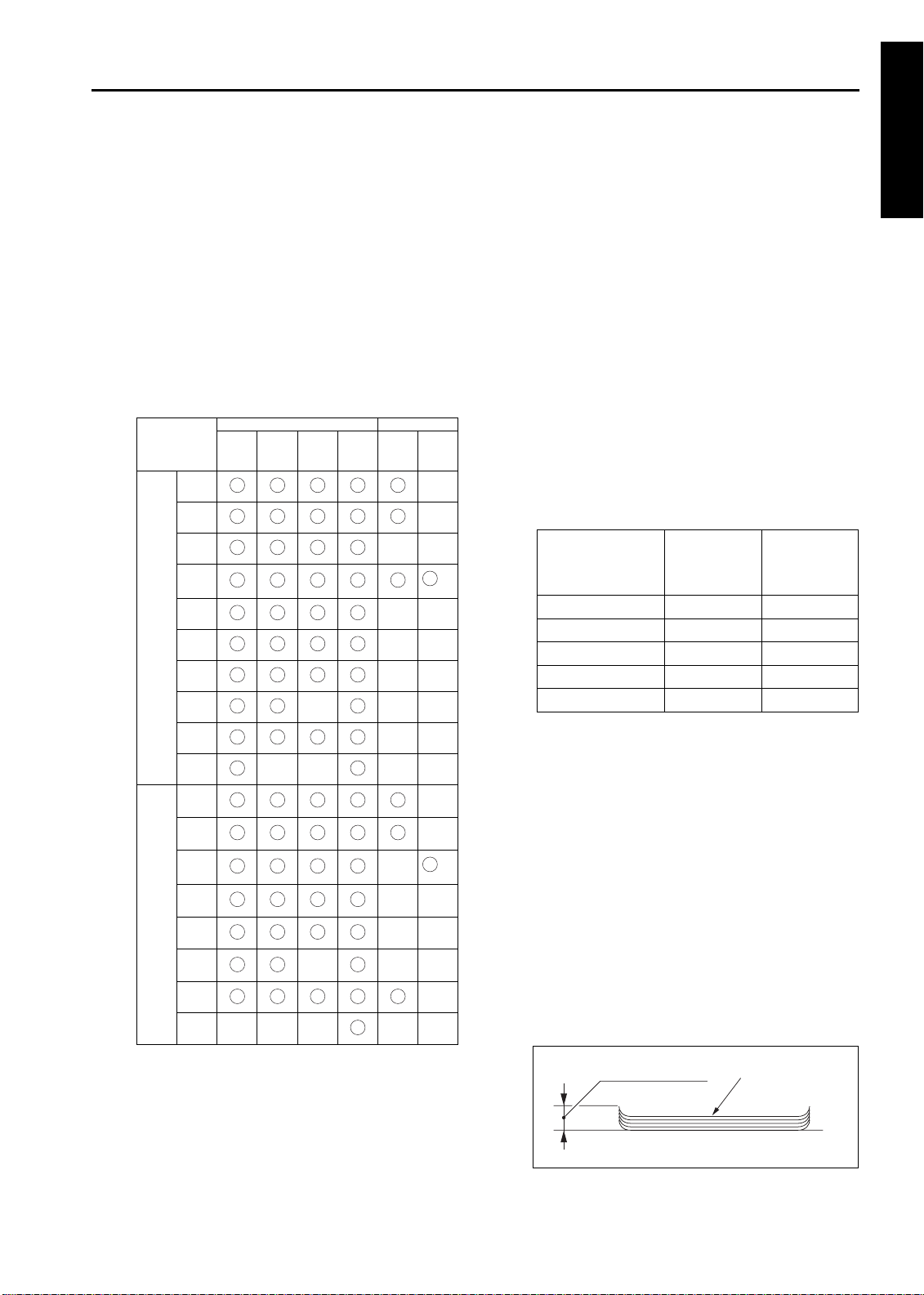
[2] Functions
T ype of Paper:
Same as the main body
Paper Size:
A3
B4
F4R
A4R
A/B
A4
standards
B5R
B5
A5R
FS-110/210 FS-210 only
Non-
Sort/
Sta-
sort
group
ple
Sub-
tray
Book-
let
Three
-folding
*1
2
Paper Stacking Capacity (80g/m
or 20lbs):
Sub-tray exit mode:
Maximum 200 sheets (same-size sheets only)
Non-Staple, Group, and Offset modes:
Maximum 1500 sheets (A3, B4, F4R, 11 x 17,
and 8.5 x 14)
Maximum 3000 sheets (A4, A4R, B5, B5R,
8.5 x 11, and 8.5 x 11R)
Maximum 500 sheets (A5, A5R, B6R, 5.5 x 8.5,
and 5.5 x 8.5R)
Note: For FS-210, the maximum stacking
capacity is 2500 sheets for A4, A4R, B5,
B5R, 8.5 x 11, and 8.5 x 11R paper .
Staple Mode:
Maximum 1000 sheets (paper must be the
same size)
Main-Tray Capacity
Original pages
A3, 11 x 17,
A5, and 5.5 x
8.5
Other paper
types
2 to 9 50 stacks 100 stacks
10 to 20 50 stacks 50 stacks
21 to 30 30 stacks 30 stacks
31 to 40 25 stacks 25 stacks
41 to 50 20 stacks 20 stacks
1 OUTLINE
A5
B6R
11 x
17
8.5 x
14
By
inch
8.5 x
11R
8.5 x
11
5.5 x
8.5R
5.5 x
8.5
Wide
Other
*1
*1 The position of the stopper must be changed
when using paper with different size.
Booklet Mode (FS-210 only):
• Stitch-and-fold
20 booklets with 5 sheet s folded each. 15
booklets in case of small size paper (A4R/
8.5 x 11R ). One booklet with 6 sheets folded
is taken as two and more booklets.
• Folding
33 booklets with 3 or less sheets folded each
25 booklets in case of small size paper
(A4R/8 .5 x 11R).
• Three-folding
Tray capacity is a maximum of 50 individual
folded s h e e ts .
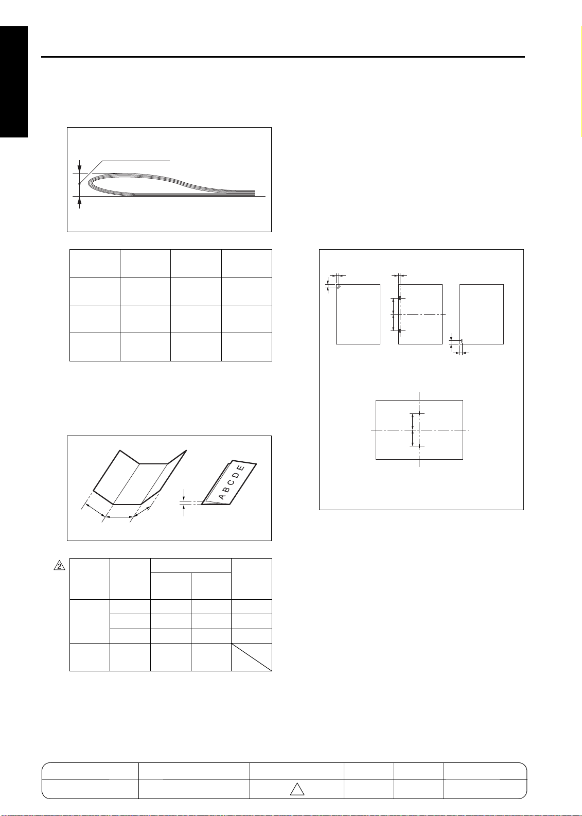
Paper curling:
10mm or less
Amount of curl
Paper (5 sheets)
1-1
Page 12
FS-110/FS-210
1 OUTLINE
Height of folding in the booklet mode (FS210
only):
(80g/m2 or 20lbs)
Height of folding
Original
pages
0 to 5
6 to 10
11 to 20
A3, 11 x 17
25mm or
less
50mm or
less
Not
specified*
B4,
8.5 x 14
25mm or
less
50mm or
less
Not
specified*
A4R,
8.5 x 11R
25mm or
less
Not
specified*
Not
specified*
* The height of folding may be larger after exit,
[3] Staple Mode
Number of sheets to be stapled:
50 sheets or less (the height must be 5mm or
less when using 80g/m
Positions for stapling:
A = 8.5mm
B = 8.5mm
C = 60mm
D = 8.5mm
E = 14mm
F = 60mm
A
B
Single staple
(rear)
3mm
±
3mm
±
3mm
±
3mm
±
3mm
±
3mm
±
D
CC
T wo staples
2
or 20lbs quality paper)
E
Single staple
D
(front)
although the booklet must be folded with ease
manually.
Width (a, b and c) and height (h) in the threefolding mode:
FF
h
a
Width/
height
Width
Height h
c
b
Measure-
ments
Nominal values
A4R
8.5 x 11R
a 95mm 89.4mm
b 101mm 95mm
c 101mm 95mm
25mm
or less
25mm
or less
Allow-
ance
2mm
±
2mm
±
2mm
±
Note: Measurements must be made using a
single sheet.
Amount of sort offsetting:
30mm (after sorting and grouping)
Booklet mode (stitch-and-fold)
(FS-210 only)
Staple capacity:
5000 staples/cartridge
MODEL MANUAL REVISED EDITION DATE PAGE METHOD
7155/7165/7255/7272
SERVICE MANUAL Dec. 2003
1-2
2
1-2 REPLACEMEN T
Page 13
FS-110/FS-210
[4] Booklet Mode (FS-210 only)
Stitch-a n d -fo ld:
Maximum 20 sheets (when using 80g/m
20lbs quality paper)
Maximum 19 sheets (when using 80g/m
20lbs qualit y paper) + one sheet ( 200g/m
45lbs quality paper)
Foldin g :
Maximum 3 sheets (when using 80g/m
20lbs quality paper)
[5] Three-folding Mode (FS-210 only)
Num b e r of three-f o ld in g :
Maximum 3 sheets (when using 80g/m
20lbs quality paper)
However, special paper cannot be used.
[6] Option
PI-110
(Cover sheet feeder)
PK-110
(Puncher)
[7] Machine Specifications
Power source:
24V, 5VDC (supplied from the main body)
Maximum power consump tion:
100V A
Weight:
FS-110: Approx. 55kg
FS-210: Approx. 65kg
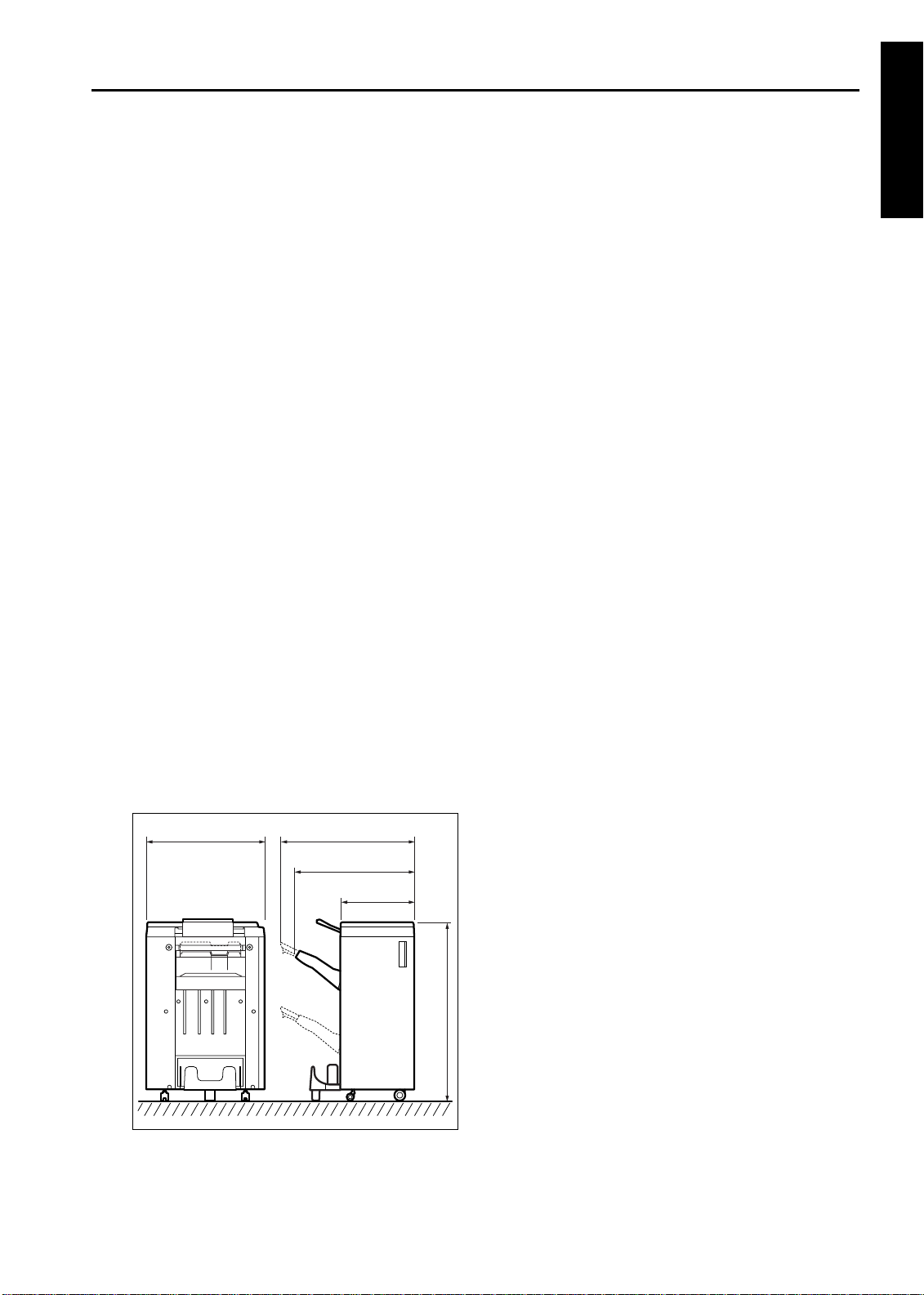
Extern a l Dimen s io n s :
2
2
2
2
2
or
or
or
or
or
[8] Maintenance
Maintenance procedures:
Same as the main body
Service life:
Same as the main body
[9] Operating Environment
T emperature:
10 to 30
Humidity:
10 to 80% RH
Note: The information herein may be subject to
change for improvement without notice.
C (50 °F to 86°F)
°
1 OUTLINE
741656
(tray extended)
656
(tray closed)
410
990
1-3
Page 14
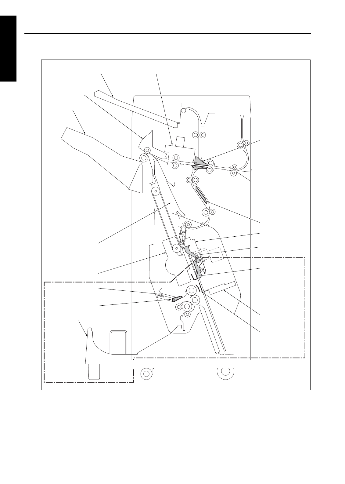
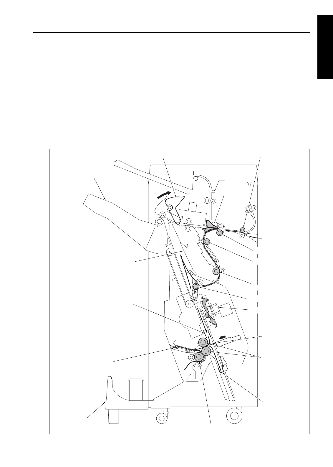
FS-110/FS-210
CROSS SECTION DIAGRAM
1 OUTLINE
Sub-tray
Paper exit
opening unit
Main tray
Shift unit
Gate
Alignment plate/U
Stapler
Three-folding
stopper
Three-folding gate
Booklet tray
Bypass gate
Clincher
Flat-stapling stopper
Booklet stopper
Folding knife
Alignment plate/L
Components in the region enclosed by the dotted line represent those of FS-210.
1-4
Page 15
DRIVE SYSTEM DIAGRAM
FS-110/FS-210
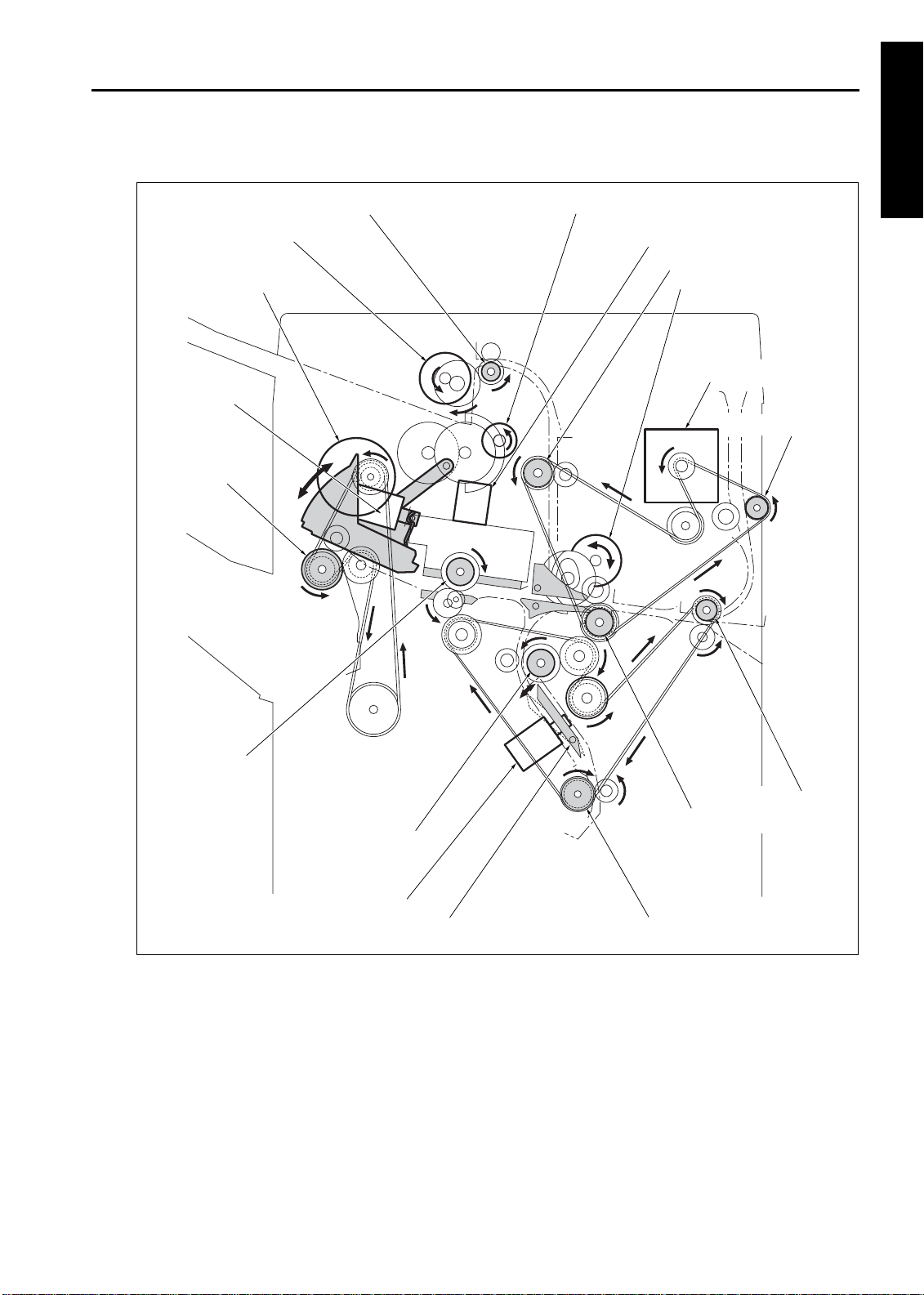
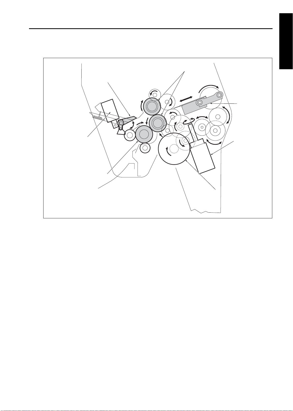
[1] Paper Conveyance Drive
Sub-tray paper exit roller
Sub-tray paper exit motor (M721)
Paper exit roller motor (M707)
Paper exit opening
SD (SD704)
Paper exit roller
1 OUTLINE
Paper exit opening motor (M708)
Shift motor (M702)
Sub-tray conveyance roller
Gate drive motor (M712)
FNS conveyance motor (M701)
PI conveyance roller
Shift roller
Conveyance roller/B
By-pass gate SD (SD705)
By-pass gate
Entrance roller
Conveyance roller/A
Intermediate conveyance roller
1-5
Page 16
FS-110/FS-210
[2] Stacker Drive
1 OUTLINE
Alignment plate/U
Paper exit arm
From paper exit roller motor (M707)
Alignment motor/U (M705)
Stacker entrance motor
(M713)
Stacker entrance roller
Flat-stapling stopper
Alignment motor/L (M716)
Alignment plate/L
Booklet stopper
Stopper motor (M718)
1-6
Page 17
FS-110/FS-210
[3] Staple Drive
Stapler/F
Clincher/F
Stapler/R
Stapler rotation motor (M706)
Stapler
Stapler movement
motor (M711)
1 OUTLINE
Clincher
Clincher/R
Clincher rotation motor
(M704)
1-7
Page 18
FS-110/FS-210
[4] Tra y Drive
1 OUTLINE
2
Up/down pulley/U
Main tray
Up/down wire
Up/down pulley/L
Old type
Tray up/down motor
(M703)
New type
fs2101001
MODEL MANUAL REVISED EDITION DATE PAGE METHOD
7155/7165/7255/7272
SERVICE MANUAL Dec. 2003
1-8
2
1-8 REPLACEMEN T
Page 19
FS-110/FS-210
[5] Folding Drive
Three-folding gate SD
(SD706)
Three-folding roller
1 OUTLINE
Folding roller
Three-folding gate
Folding knife
Folding knife motor
(M719)
Folding conveyance motor
(M720)
1-9
Page 20
FS-110/FS-210
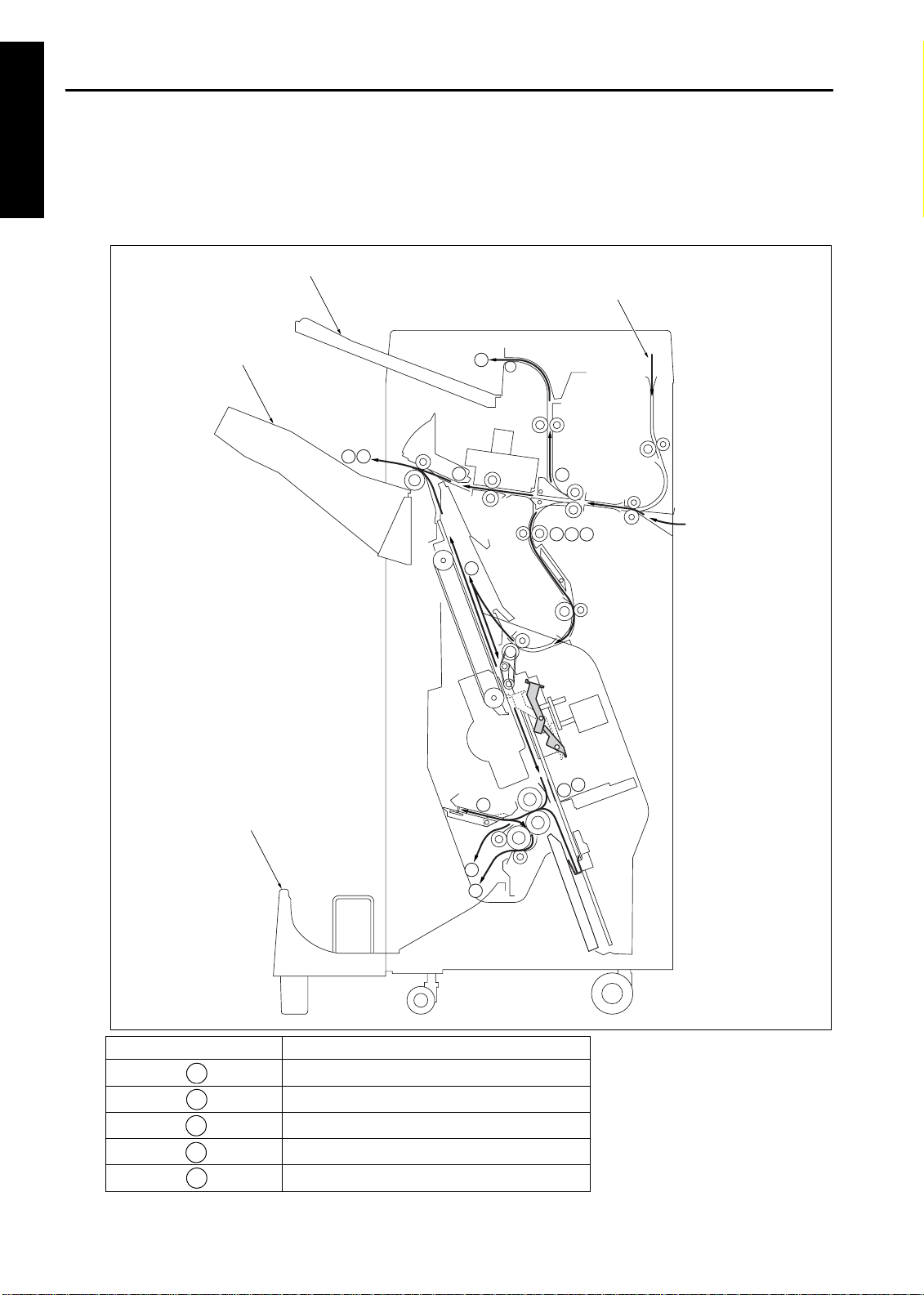
PAPER CONVEYANCE PATH
[1] Paper Conveyance Path
1 OUTLINE
The finisher (FNS) consists of five paper paths, as shown in the diagram below.
Sheets are turned over by the main body's exit page inverter, and then passed to the FNS.
The FNS has two paper entrance connections: one from the main body, and the other from PI-110 (optional).
Sub-tray
PI-110
Main tray
Booklet tray
2
3
1
1
3
5
2
3
54
5
4
Main body
4
5
Paper conveyance path Finishing mode
1
112
3
4
5
Non-sort, sort, and group modes
Sub-tray mode
Staple mode
Booklet mode (FS-210 only)
Three-folding mode (FS-210 only)
1-10
Page 21
FS-110/FS-210
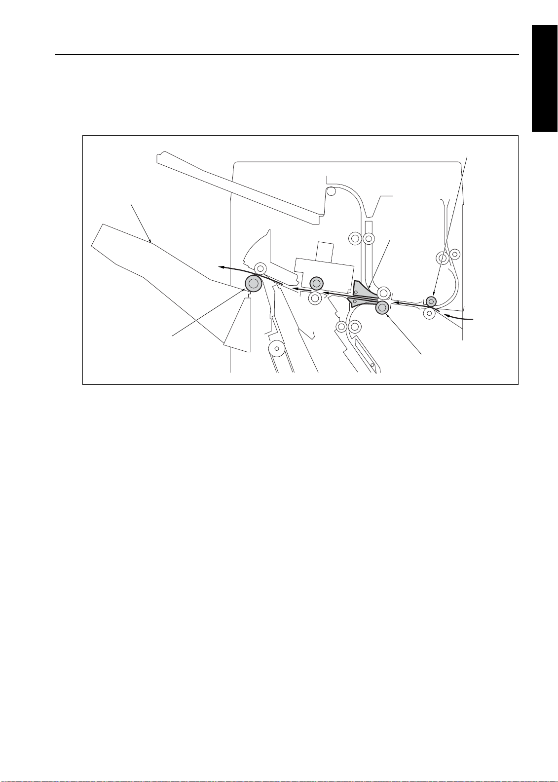
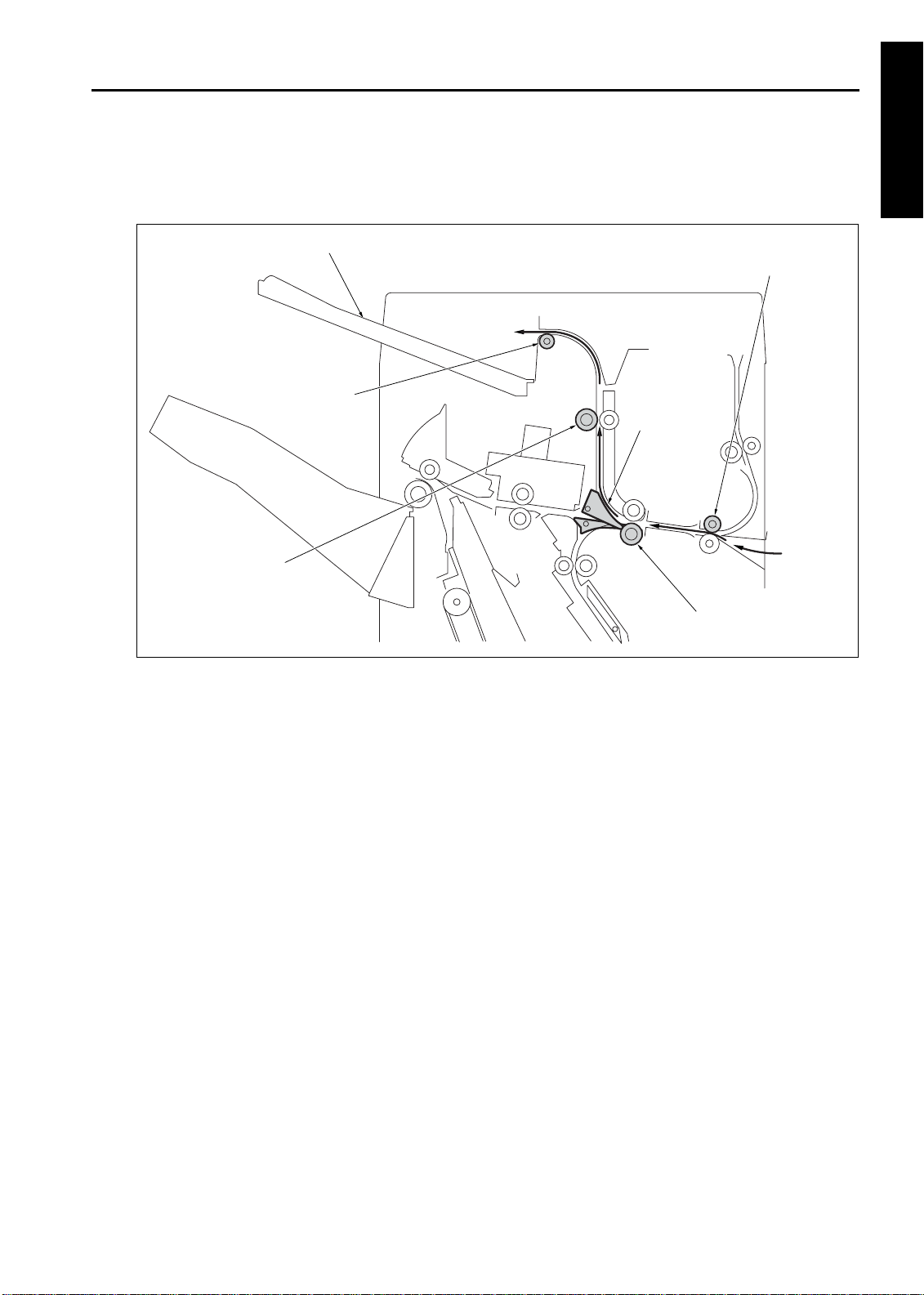
[2] Non-Sort Mode
In the non-sort mode, the gate is set to the position to carry paper to the main tray. Each sheet, delivered from
the main body, is carried to the main tray through the gate.
Entrance roller
Main tray
Gate
Paper exit roller
Conveyance roller/A
1 OUTLINE
1-11
Page 22
FS-110/FS-210
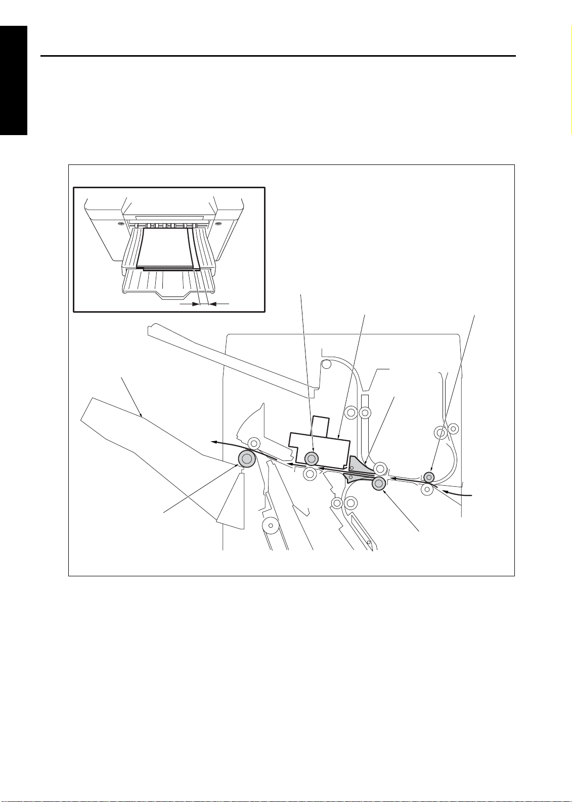
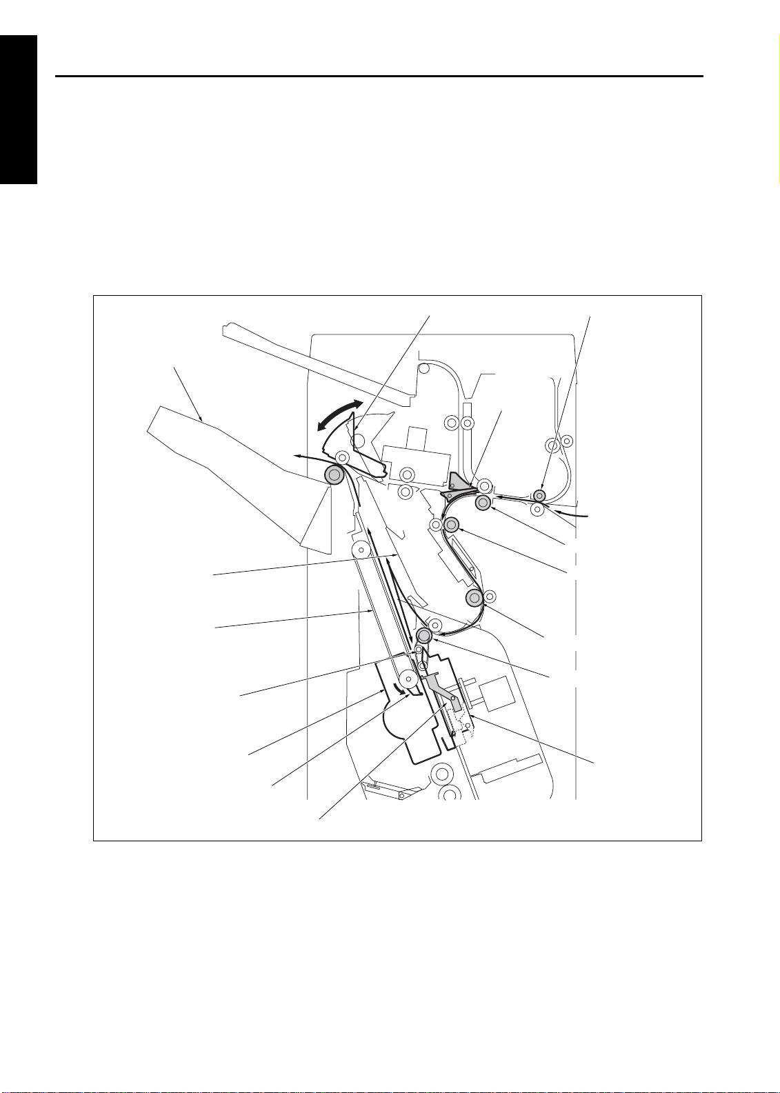
[3] Sort, and Group Modes
1 OUTLINE
In the sort and group modes, the gate is set to the position to carry paper to the main tray. Each sheet, delivered from the main body, is conveyed to the main tray while the sheet is shifted by 30mm to the r ear. The
shift roller of the shift unit performs the shift action. In the sort mode, even pages are offset. In the group mode,
even numbered copies are offset.
30mm
Shift roller
Shift unit
Entrance roller
Main tray
Paper exit roller
Gate
Conveyance roller A
1-12
Page 23
FS-110/FS-210
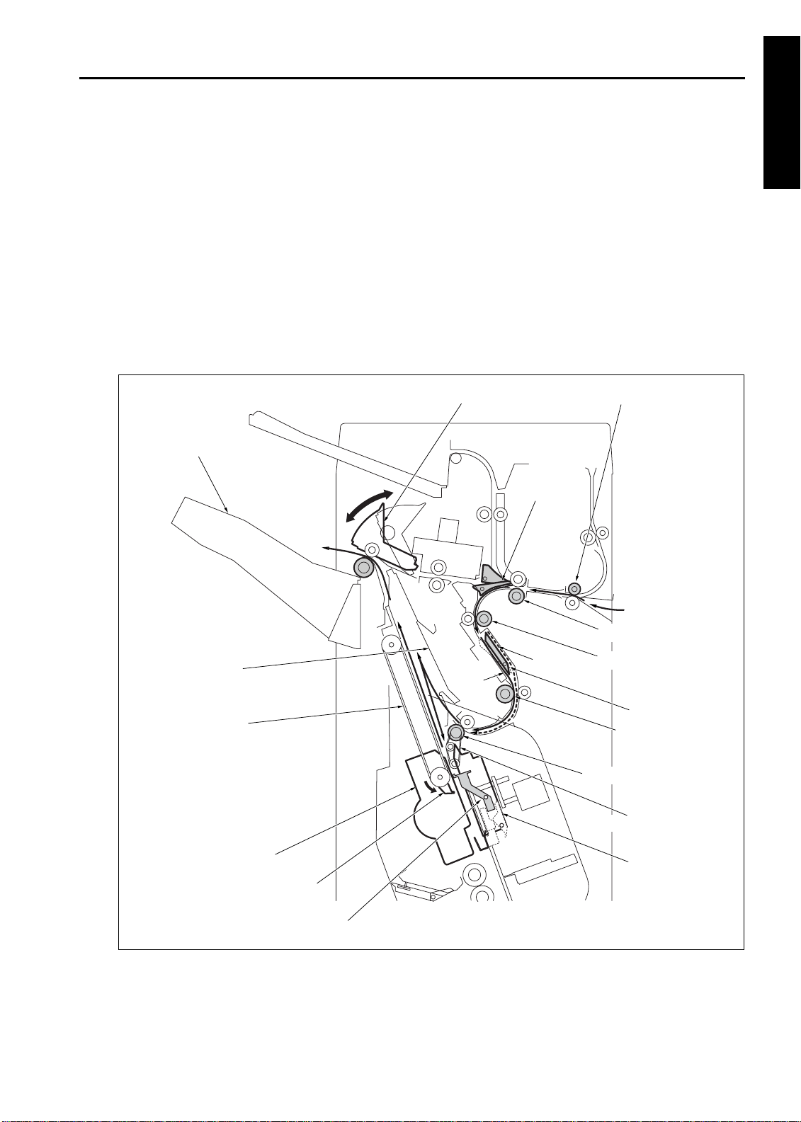
[4] Sub-tray Mode
In the sub-tray mode, the gate is set to the position to carry paper to the sub-tray. Each sheet, delivered
from the main body, is delivered to the sub-tray
Sub-tray paper exit roller
Sub-tray conveyance roller
1 OUTLINE
Sub-tray
Entrance roller
Gate
Conveyance roller/A
1-13
Page 24
FS-110/FS-210
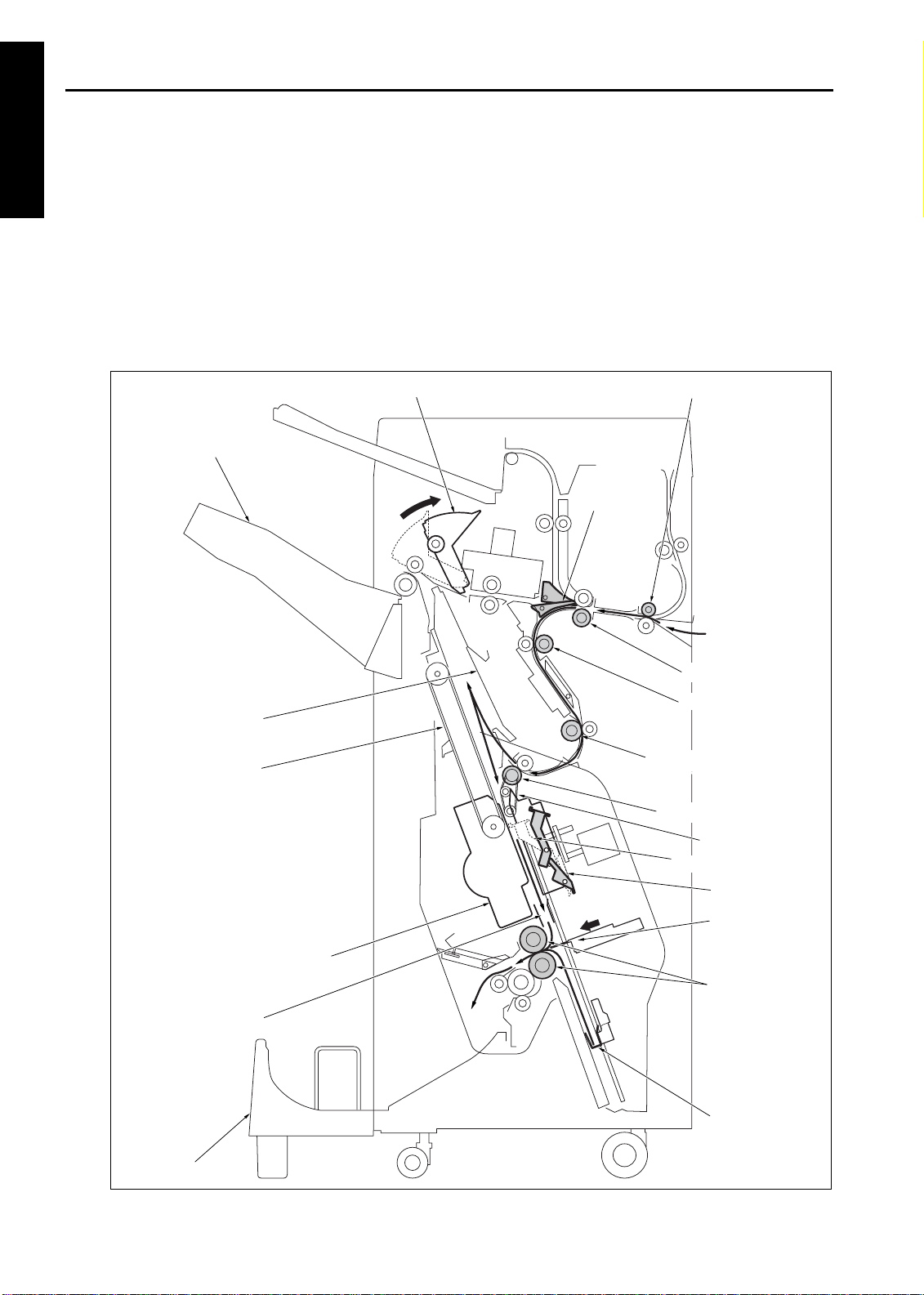
[5] Staple Mode
1 OUTLINE
For sheets of all size except A4, B5, and 8.5 x 11:
(1) The gates are set to the position to carry paper to the stacker.
(2) If paper is larger than A4R, the paper exit opening will open.
(3) Each sheet is carried to the flat-stapling stopper and its vertical position (feeding direction) is adjusted.
(4) The horizontal position (widthwise direction) of each sheet is adjusted by the alignment plate/U.
(5) When all necessary sheets are stacked, they are stapled with the stapler and the clincher.
(6) The set of stapled sheets is delivered by the paper exit arm to the main tray.
(7) Steps (3) through (6) are repeated for each set of sheets to be stapled.
Main tray
Alignment plate/U
Paper exit belt
Swing belt
Paper exit opening unit
Gate
Intermediate conveyance roller
Entrance roller
Conveyance roller/A
Conveyance roller/B
Stacker entrance roller
Stapler
Paper exit arm
Flat-stapling stopper
Clincher
1-14
Page 25
FS-110/FS-210
For sheets of A4, B5, and 8.5 x 11:
(1) The first set is stapled and delivered to the main tray in the same manner as sheets of all size except A4,
B5, and 8.5 x 11.
(2) As the front of t he f i r st set i s bei ng di schar ged, t he st ac ker ent r ance r ol l er st ops and t he by- pass gat e
opens. The first sheet of the second set (and subsequent sets) is conveyed to the stacker entrance.
(3) The by-pass gate closes, and a second sheet is l aid over the fi rst sheet which is f ixed by the st acker
entrance roller.
(4) When the front of the first set has been delivered, the stacker entrance roller starts to rotate. The first and
second sheets are conveyed to the stacker.
(5) The alignment plate/U lines up each sheet in the widthwise direction.
(6) When all sheets are stacked, they are stapled with the stapler and the clincher.
(7) The set of stapled sheets is delivered by the paper exit arm to the main tray.
(8) Steps (2) through (7) are repeated for each set of sheets.
Paper exit opening unit
Main tray
Gate
Entrance roller
1 OUTLINE
Alignment plate/U
Paper exit belt
Stapler
Paper exit arm
Flat-stapling stopper
Second
sheet
First sheet
Conveyance roller/A
Conveyance roller/B
By-pass gate
Intermediate
conveyance roller
Stacker entrance roller
Intermediate conveyance
roller
Clincher
1-15
Page 26
FS-110/FS-210
[6] Booklet Mode
1 OUTLINE
(1) The gates are set to the position to carry paper to the stacker.
(2) The paper exit opening opens.
(3) The booklet stopper lowers t o the sti tch- and-fol d positi on. The fl at-s tapli ng stopper i s rel eased as the
booklet stopper lowers.
(4) The paper is conveyed to the booklet stopper to line up sheets in the lengthwise direction.
(5) The alignment plate/U and alignment plate/L line up each sheet in the widthwise direction.
(6) When the stitch-and-fold mode is selected, the sheets are stapled by the stapler and the clincher.
(7) The booklet stopper lowers to the folding position for setting the paper to the folding position.
(8) The folding knife and the folding roller fold the sheets, which are delivered to the booklet tray.
Main tray
Alignment plate/U
Paper exit belt
Paper exit opening unit
Entrance roller
Gate
Conveyance roller/A
Conveyance roller/B
Intermediate conveyance
roller
Stacker entrance roller
Swing belt
Flat-stapling stopper
Clincher
Alignment plate/L
Booklet tray
Folding knife
Stapler
Folding roller
Booklet stopper
1-16
Page 27
FS-110/FS-210
[7] Three-folding Mode
(1) The gates are set to the position to carry paper to the stacker.
(2) The paper exit opening opens.
(3) The booklet stopper lowers t o the sti tch-and- fol d positi on. The fl at-s tapli ng stopper i s rel eased as the
booklet stopper lowers.
(4) The paper is conveyed to the booklet stopper to line up in the lengthwise direction.
(5) The alignment plate/U and the alignment plate/L line up each sheet in the widthwise direction.
(6) The booklet stopper lowers to the first folding position, and the sheet is set to the first folding position.
(7) The folding knife and the folding roller perform the first folding, and the paper is conveyed toward the three-
folding stopper.
(8) The three-folding stopper curls the sheet, and the second folding is made by drawing it to the three-folding
roller. The three-folded sheet is delivered to the booklet tray.
Paper exit opening unit
Main tray
Gate
Entrance roller
1 OUTLINE
Alignment plate/U
Alignment plate/L
Three-folding stopper
Booklet tray
Conveyance roller/A
Conveyance roller/B
Intermediate conveyance roller
Stacker entrance roller
Flat-stapling stopper
Folding knife
Folding roller
Booklet stopper
Three-folding stopper
1-17
Page 28

1 OUTLINE
Blank page
Page 29

2
UNIT EXPLANATION
2 UNIT EXPL A NATION
Page 30

2 UNIT EXPL A NATION
Blank page
Page 31

EXTERNAL SECTION
[1] Composition
FS-110/FS-210
Main paper exit cover
Main tray
Rear cover
Booklet paper exit cover
(FS-210 only)
Booklet tray
(FS-210 only)
[2] Mechanism
Mechanism Method
Jam removal*1 Through the rotation of
roller(s) and the opening/closing operation of the guide
plates.
Sub-tray
Top cover/1
Top cover/2
Front door
Side cover
2 UNIT EXPL A NATION
*1 Jam removal
When a jam occurs in the conveyance secti on,
open the front door, turn the convey ance rol ler,
open the guide plates, and remove the jammed
paper.
When a jam occurs in the stacker section, open
the front door, draw out the stacker section,
rotate the fol ding roller, open the gui de plates,
and remove the jammed paper.
2-1
Page 32

FS-110/FS-210
CONVEYANCE SECTION
[1] Composition
Sub-tray full PS (PS719)
Shift unit
Shift roller
Paper exit opening unit
2 UNIT EXPL A NATION
Main tray paper exit PS
(PS706)
Main tray paper exit roller
Sub-tray paper exit PS (PS701)
PI conveyance roller
Gate
Entrance roller
FNS entrance PS
(PS704)
Conveyance roller/A
Conveyance roller/B
By-pass gate
Intermediate conveyance roller
Conveyance section
2-2
Page 33

FS-110/FS-210
[2] Mechanism
Mechanism Method
Gate switching*1 Driven by the stepping
motor/cam.
By-pass gate*2 Solenoids
Shift mechanism
of the shift unit*3
Open/close of
paper exit opening*4
Paper exit opening
nip*5
*1 Gat e S witching
The two gates (/U and /L) switch the paper path
to three direct ions: the sub-tr ay, the main tray,
and the stacker secti on. The upper and lower
gates (/U and /L) ar e driven by the gate cam,
which is driven by the gate drive motor (M712).
Gate HP PS (PS716)
Crank mechanism
Crank mechanism
Pressure rollers driven by
solenoid.
Gate drive motor (M712)
The gate cam consists of two cams (/U and /L) on
the same shaft. The position of the cams determines the paper path.
To sub-tray
Gate/U
Gate/L
To stacker section
Gate HP PS (PS716)
Cam/U
Cam/L
Sub-tray paper exit
Stacker section
paper exit
2 UNIT EXPL A NATION
Gate/U
Main tray paper exit
Gate cam
To main tray
Gate/L
2-3
Page 34

FS-110/FS-210
*2 By-pass Gate
2 UNIT EXPL A NATION
The by-pass gate is l ocated on the path t o the
stacker. This gate changes the conveyance path
of the next sheet while the stapling is being performed, saving time and improving performance.
This gate is used for small size papers (A4, B5,
and 8.5 x 11). The gate changes the feeding
direction of the second sheet so that it is laid over
the first sheet. The first and second sheets will be
conveyed to the stacker simultaneously.
The by-pass gate SD (SD705) drives the bypass gate.
First paper of the second and
subsequent sets
First paper of the second
and subsequent sets
By-pass gate
*3 Shift Mecha n is m of the S h ift Unit
The FNS conveyance motor (M701) drives the
shift rol ler, conveying the paper forward t o the
main tra y.
While the paper is conveyed to the main tray, the
shift motor (M702) rotates to activate the crank
mechanism. This mechanism moves the shift
moving section (including the shift roller) by
300mm toward the rear, which also moves the
paper and then it is delivered.
The shift HP PS (PS718) detects t he s hift position.
To main tray
Fixed section
Shift HP PS (PS718)
Shift moving section
Shift motor
(M702)
Shift roller
Crank arm
From FNS conveyance
motor (M701)
By-pass gate SD (SD705)
Second paper of the second
and subsequent sets
Second paper of
the second and
subsequent sets
By-pass gate SD (SD705)
First paper of the second
and subsequent sets
By-pass gate
Shift HP PS (PS718)
Fixed
section
Shift moving section
Position for straight
Paper exit
Shift motor (M702)
Shift roller
Crank shaft
Position for offset
(shift) paper exit
2-4
Page 35

FS-110/FS-210
*4 Op e n /c lo s e o f Paper E x it Open in g
When paper is conveyed to the stacker, and it is
larger than B5R in t he vertical length ( feeding
direction) , it does not fi t the paper exit opening.
This mechanism addresses this problem by
opening the paper exit opening from the start of
copying until the completion of stapling.
Paper exit opening unit
To main tray
Paper exit opening HP PS (PS712)
Crank arm
Paper exit opening
motor (M708)
The paper exit opening motor (M708) rotates to
activate the cr ank mechanism, lif ting t he paper
exit opening unit. The paper exit opening opens.
*5 Pap e r Exit Op e n in g Nip
Because the rotati onal speed of the paper exit
roller is slower than that of the conveyance roller,
the nip is in the released position except during
the paper exit action. When a sheet of paper
reaches the paper exi t opening, t he paper exit
opening solenoid (SD704) activates the nip
roller. The roller nips the sheet to deli ver t o the
main tra y.
Paper exit opening unit
Paper exit opening SD
To main tray
Nip moving section (Paper exit guide assembly)
(SD704)
Nip roller
Main tray paper exit PS
(PS706)
2 UNIT EXPL A NATION
Paper exit
opening unit
Close position
Crank shaft
Paper exit opening
motor (M708)
Paper exit opening HP PS (PS712)
Open position
Position when the
nip is not active.
Nip roller
Nip moving
section
Position when the
nip is active.
Paper exit opening SD
(SD704)
Main tray paper exit
roller
2-5
Page 36

FS-110/FS-210
[3] M701 (FNS Conveyance) Control
24V
24V
DRV A
DRV A
DRV B
DRV B
5V
PS704 IN
GND
24V-IN
5V
2 UNIT EXPL A NATION
SGND
PGND
PGND
FGND
MTXD
SGND
MCTS
MRXD
SGND
MRTS
M701 (FNS conveyance) operation is performed
by the 24V DC motor and controlled by the FNS
CB (FNS Control Board).
The related signals is PS704 (FNS Entrance).
1. Operation
a. Interlock control
FNS paper conveyance drive control is initiated
by the ON signal from the main body' s START
button. If MS701 (int er lock) i s OFF at t his t i me,
however, the finisher transmits an error signal to
the main body's PRCB and does not begin thi s
control.
b. M701 (FNS conveyance) control
When the position of the START button is ON,
and the paper exit speed is high, ON from PS37
(main body paper exit) sets the speed to low, and
ON from PS704 (FNS entrance) sets the speed
to high after a predefined time peri od. For the
main tray paper exi t operation, PS704 det ects
the end of the paper, and, after a predefined time
period, the speed mode swit ches to medium to
match the paper exit speed of the FNS. Then,
after a predefined time, the mode returns to the
high speed to prepare for the next conveyance of
paper.
24VDC IN
5V
SGND
PGND
PGND
SRXD
SGND
SRTS
STXD
SGND
SCTS
FNS CBMAIN BODY
M701
PS704
2. Signals
a. Input signals
(1) SRXD (Main body to FNS CB)
Serial data line; transmits the operating status of
the main body's CB to the FNS CB.
(2) SCTS (Main body to FNS CB)
Acknowledgment signal, sent from the main
body to the FNS, allowing the FNS to send data
to the main body.
(3) 24V-IN (MS701 to FNS CB)
Interlock signal:
[H]: Front cover is closed.
[L]: Front cover is open.
(4) PS704 IN (PS704 to FNS CB)
Signal indicating whether the paper passes
through the entrance. The front and rear ends of
the paper are detected.
[H]: Paper does not exists.
[L]: Paper exist.
b. Output signals
(1) S RTS (FNS C B to Ma in b o d y )
Acknowledgment signal, sent from the FNS to
the main body, allowing the main body to send
data to the FNS.
(2) S T X D (FNS CB to Main bo d y )
Serial data line; transmits the operating status of
the FNS to the main body's CB.
(3) M701 DRV A, A
Pulse signal to drive/control the Phase A of M701
(4) M701 DRV B, B
Pulse signal to drive/control the Phase B of M701
(FNS CB to M701)
(FNS CB to M701)
2-6
Page 37

FS-110/FS-210
[4] M712 (gate drive) Control
24V
M712 DRV A
M712 DRV A
M712 DRV B
M712 DRV B
M712 (gate drive) perf orms the paper conveyance path switching between the sub-tray, main
tray or stacker section. The FNS CB (FNS control board) controls the operation of M712.
The related signal is PS716 (gate HP).
1. Operation
M712 (gate drive) is activated by the FNS operation signal from the main body, selecting one of
the three positions depending on the paper exit
destinations: the sub-tray (home position), main
tray or stacker. However, when the current paper
exit destination is the sub-tray, M712 is not activated (it is already in the home position).
After the operation, M712 returns to i ts home
position based on PS716 (gate HP).
2. Signals
a. FNS CB input signals
(1) PS716 IN (PS716 to FNS CB)
Signal relating to the gate home position
[H]: HP
[L]: Non -H P
b. FNS CB output signals
(1) M712 DRV A, A
Pulse signal to drive/control the Phase A of M712
(2) M712 DRV B, B
Pulse signal to drive/control the Phase B of M712
(FNS CB to M712)
(FNS CB to M712)
24V
5V
PS716 IN
SGND
FNS CBMAIN BODY
M712
PS716
[5] SD705 (by-pass gate) Control
24V
SD705 DRV
5V
PS704 IN
GND
FNS CBMAIN BODY
SD705 (by-pass gate) only oper ates for small
size papers (A4, B5 or 8.5 x 11). The FNS CB
(FNS control board) controls SD705.
The related signal is PS704 (FNS entrance).
1. Operation
(1) Fir st s e t:
While the sheets of the first set are being pr ocessed, SD705 (by-pass gate) does not operate.
(2) Second set:
The stapling operation for the first set is activated, and, after a predefined time, SD705 (bypass gate) is activated to pull the first sheet of the
second set toward the by-pass.
SD705 stops it operation when a predefined time
has elapsed since PS704 (FNS entrance)
detected the rear end of the first sheet of the second set.
SD705 does not operate when the second and
subsequent sheets of the second set are processed.
(3) Third and subsequent sets:
PS704 (FNS entrance) detects t he rear end of
the last sheet of the second set. Then, af ter a
predefined ti me, SD705 (by-pass gate) is acti vated to pull the first sheet of the third set toward
the by-pass.
SD705 stops it operation when a predefined time
has elapsed since PS704 (FNS entrance)
detected the rear end of the first sheet of the third
set.
SD705 does not operate when the second and
subsequent sheets of t he third and subsequent
sets are processed.
SD705
PS704
2 UNIT EXPL A NATION
2-7
Page 38

FS-110/FS-210
2. Signals
a. FNS CB output signals
(1) PS705 DRV (FNS CB to SD705)
Signal to drive/control the SD705.
[H]: SD705 is ON.
[L]: SD705 is OFF.
2 UNIT EXPL A NATION
[6] M702 (shift) Control
24V
M702 DRV
5V
PS704 IN
GND
5V
PS718 IN
GND
FNS CBMAIN BODY
M702 (shift) performs the paper offset operation
in the sort or group mode.
The FNS CB (FNS control board) controls M702.
The related signal s are PS704 (FNS entrance)
and PS718 (shift HP).
1. Operation
In the sort or group mode, PS704 (FNS
entrance) detects the rear end of the paper. After
a predefined time period, M702 (shift) operates.
Its rotati on trigger s the shift (travel) of the shif t
moving section. The shift roller, rotated by M701
(FNS conveyance), carries t he paper while the
shift operation is being performed.
The completion of the shift operation is detected
by the change of PS718 (shi ft HP) signal , f rom
OFF to ON, and then M702 is deactivated.
After a predefined time period has elapsed since
M702 was deactivated, it is activated again.
M702 stops when PS718 (shift HP) signal
changes from ON to OFF. This operation allows
the shift moving section to return to its original
position to wait for the next paper to be shifted.
This sequence of acti ons is repeated for each
sheet to achieve offsetting of paper.
M702
PS704
PS718
2-8
Page 39

FS-110/FS-210
2. Signals
a. FNS CB input signals
PS718 IN (PS718 to FNS CB)
Signal relating to the shift position
[L] to [H]: S tra ig h t position
[H] to [L]: S h ift p o s itio n
b. FNS CB output signals
(1) M702 DRV (FNS CB to M702)
Signal to drive/control M702.
[L]: M702 ON
[H]: M702 OFF
[7] M707 (paper exit roller) Control
5V
M707 P/S
M707 CLK
M707 F/R
M707 LD
PGND
PGND
24V
24V
5V
PS704 IN
GND
5V
PS706 IN
GND
5V
PS709 IN
GND
5V
PS712 IN
GND
FNS CBMAIN BODY
M707
PS704
2 UNIT EXPL A NATION
PS706
PS709
PS712
M707 (paper exit roller) drives the main tray
paper exit rol ler and the paper exit bel t of the
stacker section.
The FNS CB (FNS control board) controls M707.
The related signals are PS704 (FNS entrance),
PS706 (main tray paper exit), PS709 (paper exit
belt HP), and PS712 (paper exit opening HP).
1. Operation
a. Straight, sort, and group modes
When PS704 (FNS entrance) detects the l eading edge of the paper, M707 starts to rotate at a
high speed. When PS704 has detected the trailing edge of the paper and a predefined time
period has elapsed, the rotation of M707
changes to low. Then the paper delivery action is
performed.
When PS706 (main tray paper exit) has detected
the trailing edge of the paper (preparation for the
next paper conveyance) and a predefi ned time
period has elapsed, the rotation speed of M707
returns to h ig h .
When PS704 has detected the last paper and a
predefined time period has elapsed, M707
cease s to ro ta te .
2-9
Page 40

FS-110/FS-210
b. Staple mode (for papers whose length in the
feeding direction is smaller than B5R)
The FNS operation signal from the main body
lets M707 (paper exit roller) rotate. When PS709
(paper exit belt HP) signal has changed from
OFF to ON and a predefined time period has
elapsed, M707 stops. The paper exit arm moves
to the staple mode HP.
When the stapling operation has been completed, M707 rotates to drive the paper exit belt
of the stacker section. This action allows the
paper exit arm to lift the paper to the level of the
2 UNIT EXPL A NATION
paper exit roller, which delivers it to the main tray.
When PS709 detects the change in signal, from
OFF to ON, M707 stops.
c. Staple mode (other than those above)
The FNS operation signal from the main body
lets M707 (paper exit roller) rotate. When PS709
(paper exit belt HP) signal has changed from
OFF to ON and a predefined time period has
elapsed, M707 stops. The paper exit arm moves
to the staple mode HP.
When paper other than those described above is
used, the paper exit opening is open. The paper
exit opening i s closed by M708 upon t he completion of stapling. When PS712 (paper exit
opening HP) detects that the paper exit opening
has been closed, M707 starts r otating to dri ve
the paper exit arm. This allows the paper exit arm
to lift the paper to the level of the paper exit roller,
which delivers it to the main tray .
When PS709 detects the change in signal, from
OFF to ON, M707 stops.
d. Folding and stitch-and-fold modes
The FNS operation signal from the main body
lets M707 (paper exit roller) counter-rotate.
When PS709 (paper exit belt HP) signal has
changed from OFF to ON, M707 stops. The
paper exit arm moves to the booklet mode HP.
When the stapling operation has completed, the
paper is moved to the f olding position. At this
stage, the paper exit arm will not operate. This is
because the paper exit arm may come into contact with the paper, which is waiting for a process
at the folding position
e. Three-folding mode
The FNS operation signal from the main body
lets M707 (paper exit roller) counter-rotate.
When PS709 (paper exit belt HP) signal has
changed from OFF to ON, M707 stops. The
paper exit arm moves to the booklet mode HP.
When the paper alignment has been completed,
M707 (paper exit roller) counter-rotates helping
the paper to be carried to the three-folding position. When PS709 signal has changed from OFF
to ON, M707 stops.
2-10
Page 41

FS-110/FS-210
2. Signals
a. FNS CB input signals
(1) PS706 IN (PS706 to FNS CB)
Signal relating to the main tray paper exit.
[L]: Paper does not exist.
[H]: Paper exists.
(2) PS709 IN (PS709 to FNS CB)
Signal relating to the paper exit belt HP
[L]: Paper exit belt is not at the HP.
[H]: Paper exit belt is at the HP.
(3) PS712 IN (PS712 to FNS CB)
Signal relating to the paper exit opening HP
[L]: Paper exit opening is open.
[H]: Paper exit opening is close.
(4) M707 LD (M707 to FNS CB)
Signal relating to the rotation speed of M707
[L]: Operating at a specified rotation speed.
[H]: Operating at a speed other than a specified
rotation speed.
b. FNS CB output signals
(1) M707 P/S (FNS CB to M707)
Signal relating to rotation/stop of M707
[L]: M707 ON
[H]: M707 OFF
(2) M707 CLK (FNS CB to M707)
Signal relating to the clock for controlling the
rotation speed of M707
(3) M707 F/R (FNS CB to M707)
Signal to control the rotation direction of M707
[L]: CCW
[H]: CW
[8] SD704 (paper exit opening solenoid)
Control
24V
SD704 DRV
5V
PS704 IN
GND
5V
PS706 IN
GND
FNS CBMAIN BODY
SD704 (paper exit opening) drives the nip moving section. This solenoid al lows the ni p paper
exit roll er to fir mly contact the main tr ay paper
exit roll er for nipping the paper. The FNS CB
(FNS control board) controls the operation of
SD704.
The related signal s are PS704 (FNS entrance)
and PS706 (main tray paper exit).
1. Operation
a. SD704 ON
(1) Straight, sort, and group modes:
When PS704 (FNS entrance) has detected the
rear end of the paper, and a predefined time
period has elapsed, SD704 is activated (ON).
(2) Staple mode:
When the stapling operation has been completed and a predefined time period has elapsed,
SD704 is activated (ON) for nipping the paper.
b. SD704 OFF
In each mode, when PS706 (main tray paper
exit) has detect ed the paper and a predefined
time period has elapsed, SD704 is deactivat ed
(OFF).
SD704
PS704
PS706
2 UNIT EXPL A NATION
2. Signals
a. FNS CB output signals
(1) SD704 DRV (FNS CB to SD704)
Signal to drive/control SD704
[L]: SD704 ON
[H]: SD 7 0 4 O FF
2-11
Page 42

FS-110/FS-210
[9] M708 (paper exit opening) Control
24V
SD708 DRV
5V
PS712 IN
GND
5V
PS729 IN
GND
5V
PS729 IN
2 UNIT EXPL A NATION
MAIN BODY
In the staple (when the length of the paper in the
feeding direction is larger than B5R), booklet, or
three-fol ding mode, M708 (paper exit opening)
drives the open/close operation of the paper exit
opening through the link mechanism.
The FNS CB (FNS control board) controls the
operation of M708.
The related signals are PS712 (paper exit opening HP), PS725 (folding exit), and PS729 (folding
full PS) .
GND
5V
GND
FNS CB
M708
PS712
PS725
PS729
LED729
When PS712 (paper exit opening HP) detect s
the position closed, M708 stops.
2. Signals
a. FNS CB output signals
(1) M708 DRV (FNS CB to M708)
Signal to drive/control M708
[L]: M708 ON
[H]: M708 OFF
1. Operation
a. Staple mode (for papers whose length in the
feeding direction is larger than B5R)
The FNS operation signal from the main body
lets M708 (paper exit opening) rotate, causing
the paper exit opening to be opened.
Upon completion of the stapling operation, M708
(paper exit openi ng) rotates again to star t the
closing operation of the paper exit opening.
When PS712 (paper exit opening HP) detects
the closed position, M708 stops.
The steps above are repeated for each set of the
sheets that will be stapled .
b. Folding, stitch-and-fold, and three-folding
modes
The ON signal from the main body's ST ART button lets M708 (paper exit opening) rotate, causing the paper exit opening to be opened.
When PS725 (folding paper exit) or PS729 (folding full PS) has detected the trailing edge of the
last sheet, and a predefined time period has
elapsed since then, M708 again r otat es t o st ar t
the closing oper ation of the paper exit opening.
2-12
Page 43

FS-110/FS-210
[10] M721 (sub-tray paper exit) Control
24V
PS701 IN
PS704 IN
PS719 IN
FNS CBMAIN BODY
24V
M721
5V
PS701
GND
5V
PS704
GND
5V
PS719
GND
M721 DRV A
M721 DRV A
M721 DRV B
M721 DRV B
M721 (sub-tray paper exit), controlled by the
FNS CB (FNS control board), drives the sub-tray
paper exit roller.
The related signal s are PS701 (sub-tary paper
exit), PS704 (FNS entr ance), and PS719 (subtray full).
2. Signals
a. FNS CB input signals
(1) PS701 IN (PS701 to FNS CB)
Signal indicating the existence of the paper at the
location of the sub-tray paper exit sensor.
[L]: Paper does not exist.
[H]: Paper exists.
(2) PS719 IN (PS719 to FNS CB)
Signal indicating the sub-tray full
[L]: Sub- tra y fu ll
[H]: Sub -tra y n o t fu ll
b. FNS CB output signals
(1) M721 DRV A, A
Pulse signal to drive/control the Phase A of M721
(2) M721 DRV B, B
Pulse signal to drive/control the Phase B of M721
(FNS CB to M721)
(FNS CB to M721)
2 UNIT EXPL A NATION
1. Operation
a. M721 (sub-tray paper exit) Control
M721 (sub-tray paper exit) starts its high-speed
rotation when PS701 (sub-tray paper exit)
detects the leading edge of the paper.
When PS704 (FNS entrance) has detected the
trailing edge of the paper and a predefined time
period has elapsed si nce then, the rotation of
M721 changes to low.
When PS701 detects the trailing edge of the
paper and a predefined time period has elapsed,
M721 stops.
b. Sub-tray full detection
When the papers ejected to sub- tray reach to
specified height, PS719 (sub-tray full) turns ON,
and FNS transmits "sub-tray full" information to
the main body.
When the main body receives it, the message is
displayed on the operation panel.
2-13
Page 44

FS-110/FS-210
MAIN TRAY SECTION
[1] Composition
2
Main tray
Upper up/down pulley
2 UNIT EXPL A NATION
Up/down pulley/L
Old type
Stapler paper exit upper limit PS
(PS707)
Tray upper limit PS (PS702)
Counter reset PS (PS715)
Tray lower limit PS (PS703)
Tray up/down motor (M703)
Timing belt
New type
Tray up/down motor (M703)
fs2102001
[2] Mechanism
Mechanism Method
Main tray up/down*1 Wire drive
Paper detection*2 Photo sensor
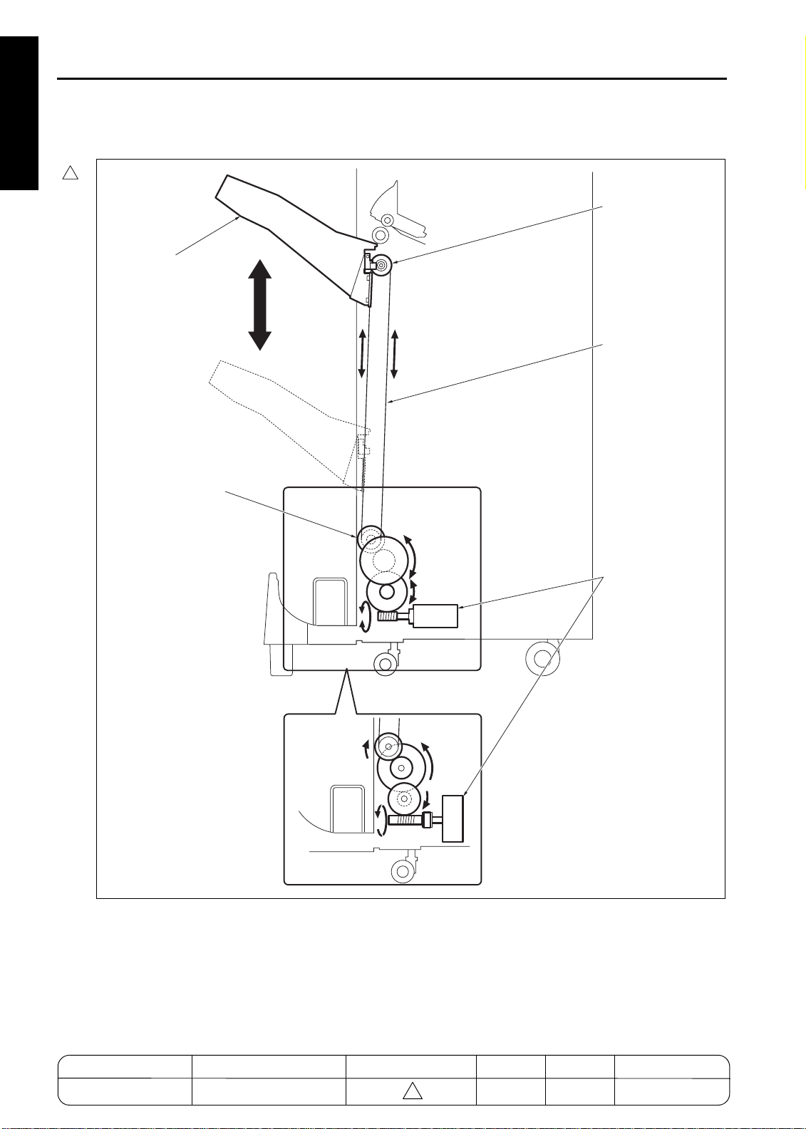
*1 Main Tray Up/Do w n
The tray up/down motor (M703) and the worm
gear installed on the motor shaft perform the
winding operation of the up/down wire. The rotation direct ion of the motor shaft deter mines the
moving direction of the main tray, i.e. rise or fall.
If the up/down pul ley/L rotates cl ockwise seen
from the front, the main tray rises. Otherwise, the
main tra y fa lls .
2
In old type, a brush motor is used for M703 but in
new type brushless motor and ti ming belt are
used to enhance the silence effectiveness.
*2 Paper Detection
The distance between the top surface of the piled
sheets on the main tray (the top surface of the
main tray if there's no sheet on the tray) and the
paper exit opening is monitored using t he tray
upper limit PS (PS702) and the stapler paper exit
upper limit PS (PS707). This distance is kept constant to avoid misalignment of delivered sheets.
The counting program, bui lt i n the FNS, count s
the number of delivered sheets on the main tray
during continuous copying. When the total number of delivered sheets reaches a maximum (values are predefined depending on type/size of
paper), the copying operation is suspended.
However, when some delivered sheets are
removed, the main tray is raised and the counter
reset PS is activated. This resets the current
sheet counter. This enables limitless delivery.
The tray lower limit PS (PS703) detects the bottom of the main tr ay. The number of deliver ed
sheets on the main tray i s not counted by the
software counter during non-continuous copying. PS703 is used for the limitation of the number.
MODEL MANUAL REVISED EDITION DATE PAGE METHOD
7155/7165/7255/7272
SERVICE MANUAL Dec. 2003
2-14
2
2-14 REPLACEMENT
Page 45

FS-110/FS-210
[3] M703 (tray up/down) Control
2
M703 DRV_F
M703 DRV_R
24V
24V
PGND
PGND
M703 H/L
M703 LD
M703 F/R
M703 CLK
M703 CONT
M703 SGND
M703 5V
5V
PS702 IN
GND
5V
PS703 IN
GND
5V
PS706 IN
GND
5V
PS707 IN
GND
5V
PS715 IN
GND
FNS CBMAIN BODY
Old type
M703
New type
M703
PS702
PS703
PS706
PS707
PS715
FS1102002
1. Operation
a. Non-sort, sort, and group modes
According to the FNS oper at ion signal from the
main body, M703 (tray up/down) elevates the
main tray until PS702 (tray upper limit) responds
(ON).
When PS706 (main tray paper exit) detect s the
paper, M703 lowers the tray. When the signal
from PS702 has changed to OFF, and a predefined time peri od has elapsed, M703 raises
the tray again. M703 stops with PS702 signal
ON.
b. Staple m o d e
When M707 (paper exit roller) has started rotating and a predefined t ime period has elapsed,
M703 (tray up/down) lowers t he main tray. The
rotation of M703 is reversed to raise the main
tray when PS706 (main tray paper exit) detects
the trail ing edge of t he paper st ack on the tr ay.
M703 stops when the signal from PS707 (stapler
paper exit upper limit) changes from ON to OFF.
2 UNIT EXPL A NATION
M703 (tray up/down) rai ses or lowers t he main
tray by a normal or reverse rotation. The FNS CB
(FNS control board) controls the operation of
M703.
The related signals are PS702 (tray upper limit),
PS703 (tray lower limit), PS707 (stapler exit
upper limit) , PS715 (count er r eset ) , and PS706
(main tray paper exit).
MODEL MANUAL REVISED EDITION DATE PAGE METHOD
7155/7165/7255/7272
SERVICE MANUAL Dec. 2003
2-15
2
2-15 REPLACEMENT
Page 46

FS-110/FS-210
2. Signals
a. FNS CB input signals
(1) PS702 IN (PS702 to FNS CB)
Signal relating to the main tray upper limit position
[L]: Non-upper limit position
[H]: Upper limit position
(2) PS703 IN (PS703 to FNS CB)
Signal relat i ng t o t he main tr ay l ower l i mit posi tion
[L]: Non- lo w e r lim it p o s itio n
[H]: Lower limit p o s itio n
(3) PS707 IN (PS707 to FNS CB)
2 UNIT EXPL A NATION
Signal relating to the main tray upper limit position in the staple mode
[L]: Upper limit position
[H]: Non-upper limit position
(4) PS715 IN (PS715 to FNS CB)
Signal relating to the counter reset
[L]: Non-counter reset position
[H]: Counter reset position
(5) M703LD (M703 to FNSCB)
2
Rotation speed detect ion speed of M703 (New
type only)
b. FNS CB output signals
(1) M703 DRV_F (FNS CB to M703)
Signal to drive/control the normal rotation of
M703 (Old type)
(2) M703 DRV_R (FNS CB to M703)
Signal to drive/control the reverse rotation of
M703 (Old type)
(3) M703 CONT (FNSCB to M703)
2
Rotation/stop control signal (New type only)
[L]: M703 ON
[H]: M703 OFF
(4) M703 CLK (FNSCB to M703)
2
Rotation speed control clock signal of M703
(New type only)
(5) M703 F/R (FNSCB to M703)
2
Rotation direction control signal (New type only)
[L]: M703 Counterclockwise
[H]: M703 Clockwise
MODEL MANUAL REVISED EDITION DATE PAGE METHOD
7155/7165/7255/7272
SERVICE MANUAL Dec. 2003
2-16
2
2-16 REPLACEMENT
Page 47

STACKER SECTION
[1] Composition
FS-110/FS-210
Paper exit arm
Paper exit belt
Stacker no paper PS (PS720)
Stacker entrance PS (PS705)
Swing belt
Flat-stapling stopper
Alignment plate/U
Alignment HP PS/U (PS708)
Coupling pin
Paper exit belt HP PS (PS709)
Stacker entrance motor (M713)
Alignment motor/U (M705)
2 UNIT EXPL A NATION
Stacker entrance roller
Folding stopper motor (M718)
Alignment HP PS/L
(PS724)
Folding stopper
HP PS (PS723)
Booklet stopper
Alignment motor/L
(M716)
Alignment plate/L
FS-210 only
2-17
Page 48

FS-110/FS-210
[2] Mechanism
Stack*1 Corrugation roller
Paper exit belt*2 Timing belt driven by
Booklet stopper*3 Driven by timing belt
2 UNIT EXPL A NATION
Paper alignment/U*4 Stepping motor
Paper alignment/L*5 Stepping motor
*1 Stack
The stacker section features a compact component design using the stack with an inclination of
70 degrees. The corrugation r oll er is employed
for the sta cker en trance roller , wh ich facilita tes a
smooth paper delivery to the stacker. The paper
sinks under its own weight into the stacker, of
which lower end is supported by the swing belt.
Mechanism Method
Swing belt + own
weight
coupling connection
using stepping motor
(the flat stapling stopper is released by the
interlocking mechanism)
Paper
Stacker entrance motor
(M713)
*2 Pap e r E x it B e lt
The paper exit arm delivers the paper to the main
tray in the staple mode, or to the folding section
in the three-folding mode. The paper exit arm is
driven by the paper exit belt, which is in turn
driven by the paper exit roller motor (M707)
through the coupling connection.
The paper exit belt HP PS (PS709) detect s t he
home position of the paper exit arm.
Paper exit roller motor
(M707)
Coupling pin
Paper exit belt HP PS
(PS709)
Paper exit arm
Paper exit belt
Stacker no paper PS
(PS720)
70 degrees
Stacker entrance PS
(PS705)
Swing belt
2-18
Page 49

FS-110/FS-210
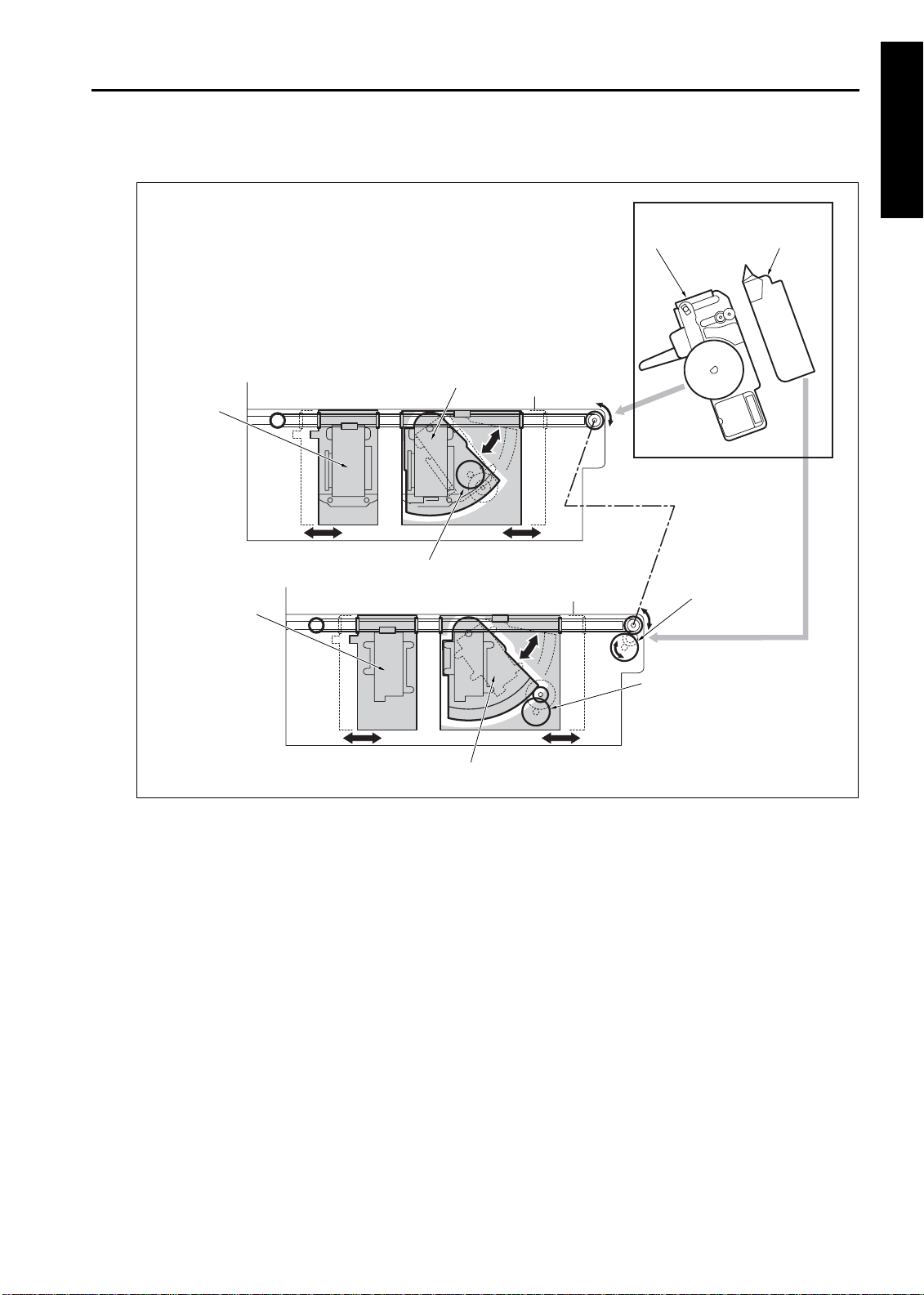
*3 Booklet Stopper (FS210 only)
The folding stopper motor (M718) oper ates t he
booklet stopper.
The folding stopper HP PS (PS723) detects the
home position of the booklet stopper. The booklet stopper is interlocked with the flat-stapling
stopper. When the booklet stopper is at its home
position, the fl at-st apli ng stopper is i n the posi tion to support t he paper by t he pr essure of the
spring. With thi s configuration, stapl ing is performed in the staple mode.
Paper
Booklet stopper
Flat-stapling stopper
Folding stopper
Spring
Stopper HP PS (PS723)
motor (M718)
Spring
When the booklet stopper l owers, the flat-stapling stopper is released via the link mechanism.
The booklet stopper catches the paper that falls.
Release
Paper
Booklet stopper
Flat-stapling stopper
Spring
One flat-stapling stopper is fixed on each of two
clinchers (R and F). When the two clinchers
move away from each other, the two stoppers
also become remote.
2 UNIT EXPL A NATION
Flat-stapling stoppers
Clincher/R
Clincher/F
2-19
Page 50

FS-110/FS-210
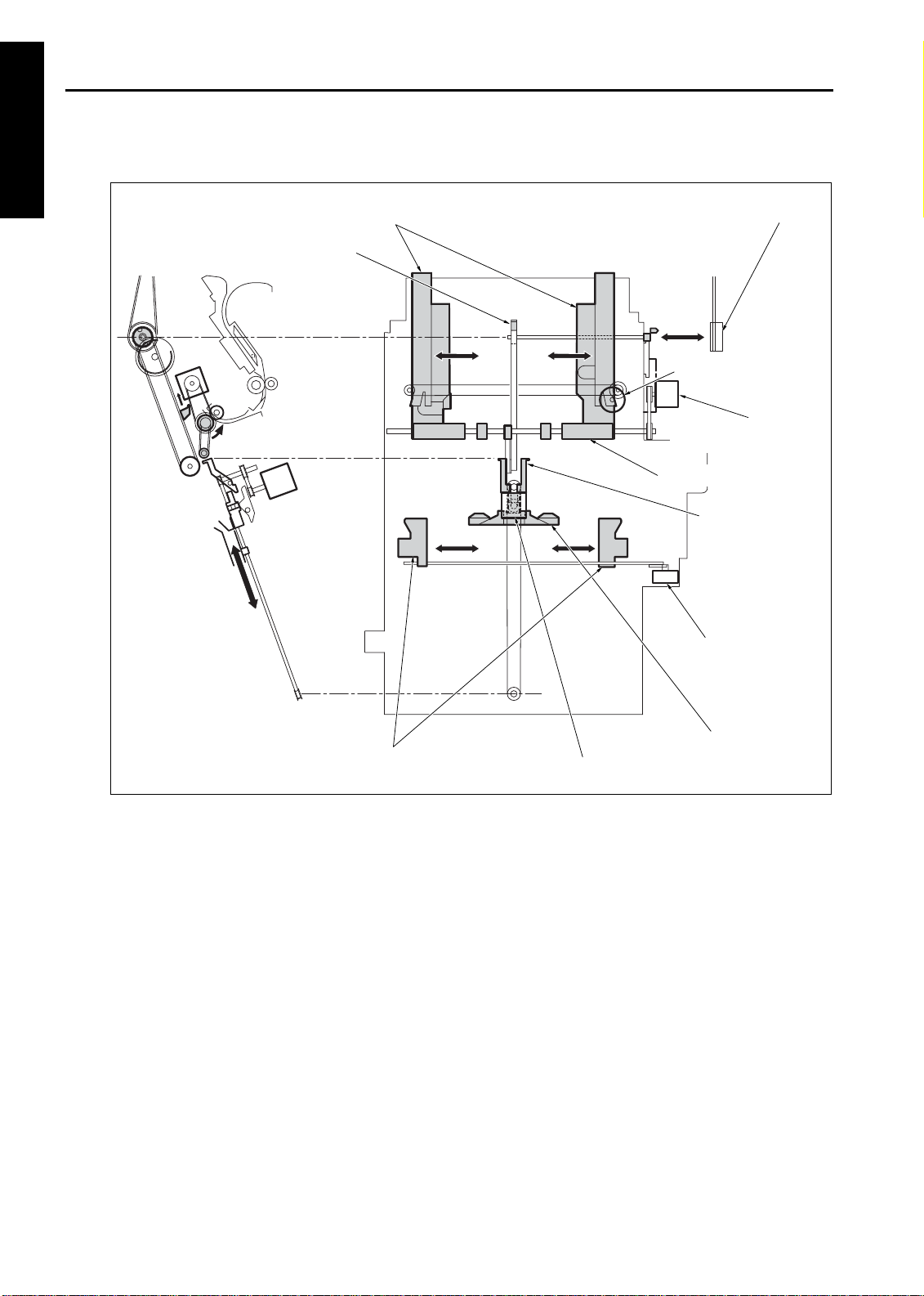
*4 Paper Alignment/U
In the staple (flat-stapling) mode, the paper
alignment plate/U (front and rear) oscillate to
align the sheets.
The oscillation of the paper alignment plate/U is
achieved by the normal and reverse rotations of
the alignment motor/ U (M705). The alignment
HP PS/U (PS708) detects the home positi on of
the paper alignment plate/U.
*5 Paper Alignment/L (FS-210 only)
In the stitch-and-fold, folding, three-folding
modes, both the paper alignment plate/U and the
2 UNIT EXPL A NATION
paper alignment plate/L oscillate to align the
sheets.
The oscillation of the paper alignment plate/L is
achieved by the normal and reverse rotations of
the alignment motor/L (M716). The alignment
HP PS/L (PS724) detects the home positi on of
the paper alignment plate/L.
2-20
Page 51

[3] M705 (alignment/U) Control
24V
M705 DRV A
M705 DRV A
M705 DRV B
M705 DRV B
24V
24V
M705 DRV A
M705 DRV A
M705 DRV B
M705 DRV B
FS-110/FS-210
M705
In the staple, folding, stitch-and-fold, three-folding modes, the widthwise alignment operation of
the paper carried into the stacker section is performed by the alignment plate/U. The space
between the two alignment pl at es/ U extends or
shrinks by means of the rotat ion of the M705
(alignment/U). The FNS CB (FNS control board)
controls the oper ation of M705 thr ough the RB
(relay board).
The related signals are PS705 (stacker
entrance) and PS708 (alignment HP/U).
1. Operation
The FNS operation signal fro m the main body
lets M705 (alignment/U) rotate so that the space
between the two alignment plates/U will become
narrower. The rotation of M705 stops when t he
plates reach their waiting positions that provide a
little wider space for the paper to be accommodated.
When PS705 (stacker entrance) has det ected
the trail ing edge of the paper and a predefi ned
time period has elapsed, the alignment plates/U
horizontally oscillate to align the paper. The
oscillatio n is pro vided by the normal and reverse
rotations of M705. This paper alignment action is
repeated each time a sheet of paper is fed.
PS705 IN
PS708 IN
FNS CB RBMAIN BODY
5V
PS705 IN
GND
5V
PS708 IN
GND
PS705
PS708
2. Signals
a. FNS CB input signals
(1) P S 7 0 5 IN (PS7 0 5 to RB to F N S CB)
Signal relat ing to the detec tion of t he paper by
the stacker entrance sensor
[L]: Paper not detected
[H]: Paper detected
(2) P S 7 0 8 IN (PS7 0 8 to RB to F N S CB)
Signal relating to the detection of the home position of the alignment plate/U
[L]: Not in th e h o me pos itio n
[H]: In the h o me pos ition
b. FNS CB output signals
(1) M705 DRV A, A
Pulse signal to drive/control the Phase A of M705
(2) M705 DRV B, B
Pulse signal to drive/control the Phase B of M705
(FNS CB to RB to M705)
(FNS CB to RB to M705)
2 UNIT EXPL A NATION
2-21
Page 52

FS-110/FS-210
[4] M716 (alignment/L) Control (FS-210 only)
2 UNIT EXPL A NATION
M718 DRV A
M718 DRV A
M718 DRV B
M718 DRV B
24V
24V
M716 DRV A
M716 DRV A
M716 DRV B
M716 DRV B
5V
PS705 IN
GND
5V
PS724 IN
GND
M716
PS705
PS724
MAIN BODY
In the folding, stitch-and-fold, three-folding
modes, the widthwise alignment operation of the
paper carried into the stacker section is performed by the alignment plate/L. The space
between the two alignment pl ates/L ext ends or
shrinks by means of the rotation of M716 (alignment/L ).
The FNS CB (FNS control board) controls the
operation of M716 through the RB (relay board).
The related signals are PS705 (stacker
entrance) and PS724 (alignment HP/L).
1. Operation
The FNS operation signal from the main body
lets M716 (alignment/L) rotate so that the space
between the two alignment plates/L will become
narrower. The rotation of M716 stops when t he
plates reach their waiting positions that provide a
little wider space for t he paper to be accommodated.
When PS705 (stacker entrance) has detect ed
the rear end of the paper and a predefined time
period has elapsed, the alignment plates/L horizontally oscillate to align the paper. The oscillation is provided by the normal and reverse
rotations of M716. This paper alignment action is
repeated each time a sheet of paper is fed.
FNS CB
RB
2. Signals
a. FNS CB input signals
(1) PS724 IN (PS724 to RB to FNS CB)
Signal relating to the detection of the home position of the alignment plate/L
[L]: Not in the home position
[H]: In the home position
b. FNS CB output signals
(1) M716 DRV A, A
Pulse signal to drive/control the Phase A of M716
(2) M716 DRV B, B
Pulse signal to drive/control the Phase B of M716
(FNS CB to R B to M716)
(FNS CB to R B to M716)
2-22
Page 53

[5] M718 (folding stopper) Control (FS-210 only)
24V
M718 CLK
M718 RESET
M718 F/R
M718 CONT
24V
24V
M718 DRV A
M718 DRV A
M718 DRV B
M718 DRV B
FS-110/FS-210
M718
MAIN BODY
M718 (folding stopper) moves the booklet stopper. The link mechanism releases the f lat-stapling stopper when the booklet stopper comes
down.
The FNS CB (FNS control board) controls t he
operation of M718 through the RB (relay board).
The signals (or sensor s) rel at ed to thi s component include PS723 (folding stopper HP), PS725
(folding paper exit) and PS729 (folding full PS).
1. Operation
a. Folding mod e
The FNS operation signal fro m the main body
lets M718 (folding stopper) drive to lower the
booklet stopper. The booklet stopper comes
down to the appropriat e al i gnment posi t i on t hat
fits the size of the paper to be handled.
When the last sheet has been aligned, M718
rotates to lo wer it to the fo ld in g p o s itio n .
When the folding has been complet ed and the
traili ng edge of the set has been detected by
PS725 (folding paper exit ), M718 is activated.
The booklet stopper is raised to t he paper-si ze
specific position. The machine waits for the
sheet of the next set.
b. Stitch-and -fo ld mode
The FNS operation signal fro m the main body
lets M718 (folding stopper) drive to lower the
booklet stopper. The booklet stopper comes
down to the appropriat e st i tch- and-f ol d posi t ion
that fits the size of the paper.
PS723 IN
PS725 IN
FNS CB
5V
PS723 IN
GND
5V
PS725 IN
GND
RB
PS723
PS725
When the stapling has been completed,M718
rotates to lower the paper to the folding position.
When the folding has been complet ed and the
traili ng edge of the set has been detected by
PS725 (folding paper exit ), M718 is activated.
The booklet stopper is rai sed to the paper- size
specific position. The machine waits for the
sheet of the next set.
c. Three-folding mode
The FNS operation signal from the main body
lets M718 (folding stopper) drive to lower the
booklet stopper. The booklet stopper comes
down to the appropri at e al i gnment posi t i on t hat
fits the size of the paper.
When the last sheet has been aligned, M718
operate s to low er it to the first folding position for
three-folding.
When the folding has been complet ed and the
traili ng edge of the set has been detected by
PS729 (folding ful l PS), M718 is acti vated. The
booklet stopper is raised to the paper-size specific position. The machine waits for the sheet of
the next set.
2 UNIT EXPL A NATION
2-23
Page 54

FS-110/FS-210
2. Signals
a. FNS CB input signals
(1) PS723 IN (PS723 to RB to FNS CB)
Signal relating to the detection of the booklet
stopper's home position
[L]: Not in the home position
[H]: In the home position
(2) PS725 IN (PS725 to RB to FNS CB)
Signal relating to the detection of the paper at the
folding paper exit position
[L]: Paper not detected
[H]: Paper detected
b. FNS CB output signals
2 UNIT EXPL A NATION
(1) M718 CLK (FNS CB to RB)
Signal relating to the clock for controlling the
rotation speed of the M718
(2) M718 RESET (FNS CB to RB)
Reset signal for the M718
(3) M718 F/R (FNS CB to RB)
Signal to control the rotation direction of the
M718
[L]: CCW
[H]: CW
(4) M718 CONT (FNS CB to RB)
Signal to activate or deactivate the M718
[L]: M718 ON
[H]: M718 OFF
c. RB output signals
(1) M718 DRV A, A
Pulse signal to drive/control the Phase A of
M718
(2) M718 DRV B, B
Pulse signal to drive/control the Phase B of
M718
(RB to M718)
(RB to M718)
2-24
Page 55

[6] M713 (stacker entrance) Control
24V
M713 CLK
M713 RESET
M713 CONT
24V
24V
M713 DRV A
M713 DRV A
M713 DRV B
M713 DRV B
FS-110/FS-210
M713
PS705 IN
PS725 IN
PS704 IN
MAIN BODY
FNS CB
M713 (stacker entrance) drives the stacker
entrance roll er and the swing belt . These components are responsible for conveying the paper
to the stacker, aligni ng the paper r ear end, and
controlling the timing for stapling.
The FNS CB (FNS control board) controls t he
operation of M713 through the RB (relay board).
The related signal s are PS704 (FNS entrance),
PS705 (stacker entrance) , and PS725 (folding
paper exit).
1. Operation
a. Staple mode (for sheets of all paper sizes
except A4, B5, and 8.5 x 11 = without by-pass
feature)
The FNS operation signal fro m the main body
lets M713 (stacker ent r ance) start to rot at e at a
high-speed.
When PS705 (stacker entrance) has det ected
the rear end of t he paper, the rot at ion speed of
M713 changes to low, conveying the paper
slowly to the st acker. Then, after a predefined
time has elapsed, the rotation returns to the highspeed mode to prepare for the next conveyance
of paper.
When the last sheet of the set has passed
through and the stapl ing oper ation has start ed,
M713 stops.
5V
PS705 IN
GND
5V
PS725 IN
GND
RB
5V
PS704
GND
PS705
PS725
When M708 (paper exit) has closed the opening,
the rotation of M713 changes to a high speed to
prepare for the conveyance of the paper to be
stapled.
b. Stapl e mode (for sheets of paper sizes A4,
B5, and 8.5 x 11 = with by-pass feature)
(1) Sheets of the first set
The sheets of the f ir st set are pr ocessed i n the
same way as in the staple mode described
above (for sheets of al l paper si zes except A4,
B5, and 8.5 x 11 = without by-pass feature).
(2) First sheets of the second and subsequent sets
When PS705 (stacker entrance) has det ected
the rear end of the last sheet of the first set, and
a predefined time period has elapsed, M713
(stacker entrance) stops. This action ensures
that the stapling of the first set completes before
the sheets of the second set are fed to the
stacker section ( the f ir st sheet waits on the bypass channel).
2 UNIT EXPL A NATION
2-25
Page 56

FS-110/FS-210
(3) Second sheets of the second and subsequent
sets
When PS704 (FNS entrance) has detected the
traili ng edge of t he s econd sheet of t he second
(and subsequent sets), and a predefined time
period has elapsed, M713 (stacker entrance)
rotates as a hi gh speed. Thi s acti on allows t he
first and s econd sheets to be conveyed to the
stacker section at the same time.
(4) Third and subsequent sheets of the second and
subsequent sets
The third and subsequent sheets of the second
2 UNIT EXPL A NATION
(and subsequent sets) are conveyed to the
stacker in the same manner as the sheets of the
first set.
c. Folding and stitch-and- folding modes
The FNS operation signal from the main body
lets M713 (stacker ent r ance) start to rotate at a
high-speed.
When PS705 (stacker entrance) has detect ed
the rear end of t he paper, the rot at ion speed of
M713 changes to low, conveying the paper
slowly to t he stacker. Then, after a predefi ned
time has elapsed, the rotation returns to the highspeed mode to prepare for the next conveyance
of paper.
When the last sheet of the set has been aligned,
M713 stops.
When PS725 (folding paper exit ) has detected
the rear end of the set, M713 (stacker entrance)
returns to i ts high-speed rotati on mode to prepare for the next paper conveyance.
d. Three-folding mode
The FNS operation signal from the main body
lets M713 (stacker ent r ance) start to rotate at a
high-speed.
When PS705 (stacker entrance) has detect ed
the trailing edge of the paper, the rotation speed
of M713 changes to low, conveying the paper
slowly to t he stacker. Then, after a predefi ned
time has elapsed, the rotation returns to the highspeed mode to prepare for the next conveyance
of paper.
When the last sheet of the set has been aligned
and the booklet stopper has moved to the threefolding position, M713 stops.
When PS729 (folding full) has detected the trailing edge of the set, M713 (stacker entrance)
returns to i ts high-speed rotati on mode to prepare for the next paper conveyance.
2. Signals
a. FNS CB output signals
(1) M 7 1 3 C L K (FNS CB to R B )
Signal relating to the clock for controlling the
rotation speed of M713
(2) M 7 1 3 R ESET (F NS CB to RB )
Reset signal for M713
(3) M 7 1 3 C ONT (FNS C B to RB )
Signal to activate or deactivate M713
[L]: M713 ON
[H]: M713 OFF
b. RB output signals
(1) M713 DRV A, A
Pulse signal to drive/control the Phase A of M713
(2) M713 DRV B, B
Pulse signal to drive/control the Phase B of M713
(RB to M713)
(RB to M713)
2-26
Page 57

STAPLER SECTION
[1] Composition
Stapler movement HP PS (PS711)
Stapler/F
FS-110/FS-210
Stapler/R
Stapler rotation motor (M706)
Stapler movement motor (M711)
2 UNIT EXPL A NATION
Stapler rotation HP PS (PS713)
Staple SW/R (SW702)
Staple SW/F (SW704)
Cartridge SW/R (SW701)
Cartridge SW/F (SW703)
Stapler HP PS/R (PS730)
Stapler HP PS/F (PS731)
Stapler motor/R (M709)
Stapler motor/F (M714)
Clincher rotation HP PS (PS714)
Clincher/F
Stapler/R/F
Clincher HP PS/R (PS732)
Clincher HP PS/F (PS733)
Clincher rotation motor (M704)
Clincher/R
Clincher/R/F
Clincher motor/R (M710)
Clincher motor/F (M715)
2-27
Page 58

FS-110/FS-210
[2] Mechanism
Mechanism Method
Stapler horizontal
movement*1
Stapler/clincher rotational movement*2
Stapling*3 Flat clinch
*1 Stapler horizontal movement
2 UNIT EXPL A NATION
The stapler movement motor (M711) drives the
timing belts. The stapler/R is attached to the
upper part of one timing belt. Also the clincher/R
is attached t o the upper part of another timing
belt. The stapler/F and the clincher/F are
attached to the lower part of each timing belt.
Stapler movement HP PS (PS711)
Stapler
Interlocked mechanism by stapler and
clincher with stepping
motor and timing belt
Stepping motor Ball
locking mechanism
*2 Stapler/clincher rotational movement
The stapler/R and clincher/R are rotatable up to
45
for the single staple (rear).
°
The stapler rotation motor (M706) rotates the
stapler/R. The clincher rotation motor (M704)
rotates the clinch e r/R.
The ball lock mechanism locks the stapler/
clincher at angles of 0
Stapler rotation motor (M706)
Stapler rotation HP PS
(PS713)
or 45°.
°
Clincher rotation motor (M706)
Stapler movement HP PS (PS711)
Clincher rotation HP PS (PS714)
Spring
Ball
Clincher
Locked Released
2-28
Page 59

*3 Stap lin g
For stapling, first the st apler motors /R and /F
(M709 and M714) in the staplers /R and /F push
out the paper pressure uni t to press the paper
respectively. Then the staples are pu shed out.
Finally, the staples are folded inside by the force
of the clincher motors /R and /F (M710 and
M715) mounted in the clinchers /R and /F
respectively.
Paper
Stapler
Clincher
FS-110/FS-210
2 UNIT EXPL A NATION
Clincher
Staple
Paper
Staple
Stapler
2-29
Page 60

FS-110/FS-210
[3] Stapler Movement Control
M704 DRV A
M704 DRV A
M704 DRV B
M704 DRV B
PS714 IN
M706 DRV A
2 UNIT EXPL A NATION
M706 DRV A
M706 DRV B
M706 DRV B
PS713 IN
M711 DRV A
M711 DRV A
M711 DRV B
M711 DRV B
PS711 IN
M704 DRV A
M704 DRV A
M704 DRV B
M704 DRV B
5V
PS714 IN
GND
M706 DRV A
M706 DRV A
M706 DRV B
M706 DRV B
5V
PS713 IN
GND
M711 DRV A
M711 DRV A
M711 DRV B
M711 DRV B
5V
PS711 IN
GND
RB
M704
PS714
M706
PS713
M711
PS711
MAIN BODY
FNS CB
The stapler/F and the st apler/R move horizontally i n opposite direct ions each other. In addition, the stapler/R rotates up to 45
according to
°
the current staple mode.
The horizontal movement of the staplers is performed by M711 (stapler movement), whereas
the rotation is performed by M704 (clincher rotation) and M706 (staple rotation).
The FNS CB (FNS control board) controls the
operations of M711, M704, and M706 through
the RB (relay board).
The related signal s are PS711 (st apler movement HP), PS713 (stapler rotation HP), and
PS714 (clincher rotation HP).
1. Operation
a. Single staple (front)
The FNS operation signal from the main body
activates M711 (stapler movement) to carry t he
staplers to extend the distance between the staplers and the clinchers, and then M711 stops at
the appropriate positions.
When PS706 (main tray paper exit) has detected
the last sheet and a pr edefined time period has
elapsed, M711 is activated again to move the
staplers to the home posit ion, and M711 stops
when PS711 (stapler movement HP) turns ON.
2-30
Page 61

FS-110/FS-210
b. Single staple (rear, oblique)
The FNS operation signal fro m the main body
activates M711 (stapler movement) to extend the
distances between the two staples as well as the
two clinchers. After a predefined time period has
elapsed, M706 (stapler rotation) and M704
(clincher rotation) start to rotate the stapler/R
and the clincher/ R respectively. When the staplers and clinchers are set in place, M704, M706,
and M711 stop.
PS706 (main tray paper exit) turns ON by detecting the last paper, and aft er a predefined ti me
has elapsed, M704 and M706 start to rotate the
stapler/R and t he clincher/R back to their home
positions. The r otating actions of the stapler/R
and the clincher/R stop when PS713 (stapler
rotation HP) and PS714 ( clincher rotati on HP)
detect them respectively. At the same time, M71 1
starts moving the staplers to the home position.
The operation of M711 stops when PS711 (stapler movement HP) turns ON.
c. Two staples
When two staples are used, the staplers and the
clinchers stay in their home positions for the stapling operation.
2. Signals
a. FNS CB input signals
(1) P S 7 11 IN (PS711 to RB to F NS CB )
Signal indicating whether the staplers (/F and /R)
are in the home position
[L]: Not in th e h o me pos itio n
[H]: In the h o me pos ition
(2) P S 7 1 3 IN (PS7 1 3 to RB to F N S CB)
Signal indi cat ing whether the stapler/R is in the
home position
[L]: Not in th e h o me pos itio n
[H]: In the h o me pos ition
(3) P S 7 1 4 IN (PS7 1 4 to RB to F N S CB)
Signal indicating whether the clincher/R is in the
home position
[L]: Not in th e h o me pos itio n
[H]: In the h o me pos ition
b. FNS CB output signals
(1) M704 DRV A, A
Pulse signal to drive/control the Phase A of M704
(2) M704 DRV B, B
Pulse signal to drive/control the Phase B of M704
(3) M706 DRV A, A
Pulse signal to drive/control the Phase A of M706
(4) M706 DRV B, B
Pulse signal to drive/control the Phase B of M706
(5) M711 DRV A, A
Pulse signal to drive/control the Phase A of M711
(6) M711 DRV B, B
Pulse signal to drive/control the Phase B of M711
(FNSCB to RB to M704)
(FNSCB to R B to M704)
(FNSCB to RB to M706)
(FNSCB to RB to M706)
(FNSCB to R B to M711)
(FNSCB to R B to M711)
2 UNIT EXPL A NATION
2-31
Page 62

FS-110/FS-210
[4] Staple Control
M709 CONT
M709 F/R
R_DHP
R_CST
R_LS
M709 CONT
M709 F/R
2 UNIT EXPL A NATION
M714 CONT
M714 F/R
F_DHP
F_CST
F_LS
M709 DRV 1
M709 DRV 1
M709 DRV 2
M709 DRV 2
5V
R_DHP
R_CST
R_LS
SGND
SGND
M714 DRV 1
M714 DRV 1
M714 DRV 2
M714 DRV 2
5V
F_DHP
F_CST
F_LS
SGND
SGND
M709 DRV 1
M709 DRV 1
M709 DRV 2
M709 DRV 2
R_DHP
SGND
5V
R_CST
5V
R_LS
M714 DRV 1
M714 DRV 1
M714 DRV 2
M714 DRV 2
F_DHP
GND
5V
F_CST
5V
F_LS
M709
5V
PS730
SW701
SW702
M714
5V
PS731
SW703
SW704
M710 CONT
R_CHP
M715 CONT
F_CHP
FNS CB
The stapling operat ion is performed using f our
motors: M709 (stapler/R), M714 (stapler/F),
M710 (clincher/R), and M715 (clincher/F).
The stapler pushes out the staple, which is bent
by the clincher.
The FNS CB (FNS control board) controls the
operations of the four motors: M709, M714,
M710, and M715.
24V
24V
M710 DRV F
M710 DRV R
5V
R_CHP
SGND
24V
24V
M715 DRV F
M715 DRV R
5V
F_CHP
SGND
RBMAIN BODY
M710 DRV F
M710 DRV R
5V
R_CHP
SGND
M715 DRV F
M715 DRV R
5V
F_CHP
SGND
The related signals ar e PS730 (stapler HP PS/
R), PS731 (stapler HP /F), PS732 (clincher HP /
R), PS733 (clincher HP /F) , SW701 (cartr i dge /
R), SW703 (cartridge /F), SW702 (staple /R),
and SW704 (staple /F).
M710
PS732
M715
PS733
2-32
Page 63

FS-110/FS-210
1. Operation
a. Staple
Upon completion of the al ignment oper ati on by
the alignment plates, M709 and M714 (stapler /
R and /F) init iate the operation of pushing the
needles into the paper. After a predefined t ime
period has elapsed, M710 and M715 (clincher /
R and /F) start bending of the needles. The stapling operati on finishes when PS732 (clincher
HP /R) and PS733 (clincher HP /F) as well as
PS730 (stapler HP /R) and PS731 (stapler HP /
F) detect the cl incher s and the st apler s at t heir
home positions (OFF to ON).
b. Staple clogging detection
During the stapling action, if one or more signals
from PS730, PS731 (stapler HP /R and /F),
PS732 and/or PS733 (clincher HP /R and /F) do
not return to ON within a predefined time period
since they have changed to OFF, the machine
recognizes that a needle clogging error has
occurred. In thi s case, M709, M714 (stapl er /R
and /F), M710, and M715 (clincher /R and /F) initiate reverse rotations to return the staplers and
the clinchers to their home positions.
c. Cartridge detection
SW701 and SW703 (cartridge /R and /F) i n t he
staplers detects whether the cartridges are properly installed or not.
If the cartridge is not found or is considered to be
improperly inst alled, an error message will be
displayed on the LCD of the main body .
d. Staple detection control
When SW702 (staple /R) or SW704 (staple /F)
detects the state of no needle remaining staples,
an error message will be displayed on the LCD of
the main body.
2. Signals
a. FNS CB input signals
(1) R_DHP (PS730 to RB to FNS CB)
Signal from the stapler HP PS/R, indicating
whether the stapler/R is in the home position
[L]: In the home position
[H]: Not in the home position
(2) F_DHP (PS731 to RB to FNS CB)
Signal from the stapler HP PS/F, indicating
whether the stapler/F is in the home position
[L]: In the home position
[H]: Not in the home position
(3) R_CHP (PS732 to RB to FNS CB)
Signal from the clincher HP PS/R, indicating
whether the clincher/R is in the home position
[L]: In the home position
[H]: Not in the home position
(4) F_CHP (PS733 to RB to FNS CB)
Signal from the clincher HP PS/F, indicating
whether the clincher/F is in the home position
[L]: In the home position
[H]: Not in the home position
(5) R_CST (SW701 to RB to FNS CB)
Signal from the cartridge SW/R, indicating
whether the cartridge is properly installed
[L]: Prop e rly in s ta lle d
[H]: Not properly installed
(6) R _ L S (S W702 to R B to FN S CB)
Signal from the staple SW/R, indicating the
remaining volume of needles
[L]: Sufficient staples
[H]: Out of staples
(7) F_CST (SW703 to RB to FNS CB)
Signal from the cartridge SW/F, indicating
whether the cartridge is properly installed
[L]: Prop e rly in s ta lle d
[H]: Not properly installed
(8) F_LS (SW704 to RB to FNS CB)
Signal from the staple SW/F, indicating the
remaining volume of staples.
[L]: Sufficient staples.
[H]: Out of staples .
2 UNIT EXPL A NATION
2-33
Page 64

FS-110/FS-210
b. FNS CB output signals
(1) M709 CONT (FNS CB to RB)
Signal to activate or deactivate M709
[L]: M709 ON
[H]: M709 OFF
(2) M709 F/R (FNS CB to RB)
Signal to control the rotation direction of M709
[L]: CW
[H]: CC W
(3) M710 CONT (FNS CB to RB)
Signal to activate or deactivate M710
[L]: M710 ON
2 UNIT EXPL A NATION
[H]: M710 OFF
(4) M714 CONT (FNS CB to RB)
Signal to activate or deactivate M714
[L]: M714 ON
[H]: M714 OFF
(5) M714 F/R (FNS CB to RB)
Signal to control the rotation direction of M714
[L]: CW
[H]: CC W
(6) M715 CONT (FNS CB to RB)
Signal to activate or deactivate M715
[L]: M715 ON
[H]: M715 OFF
c. RB output signals
(1) M709 DRV 1 (RB to M709)
Pulse signal to drive/control the Phase A of M709
(2) M709 DRV 2 (RB to M709)
Pulse signal to drive/control the Phase B of M709
(3) M710 F (RB to M710)
Pulse signal to start or stop the normal rotation of
M710
(4) M710 R (RB to M710)
Pulse signal to start or stop the reverse rotation
of M710
(5) M714 DRV 1 (RB to M714)
Pulse signal to drive/control the Phase A of M714
(6) M714 DRV 2 (RB to M714)
Pulse signal to drive/control the Phase B of M714
(7) M715 F (RB to M715)
Pulse signal to start or stop the normal rotation of
M715
(8) M715 R (RB to M710)
Pulse signal to start or stop the reverse rotation
of M715
2-34
Page 65

FS-110/FS-210
FOLDING/THREE-FOLDING SECTION (FS-210 ONLY)
[1] Composition
Three-folding gate SD (SD706)
Folding paper exit PS (PS725)
Three-folding gate
Folding conveyance (M720)
Folding full PS (PS729)
Three-folding stopper
Folding roller
Folding full LED (LED729)
Three-folding roller
Three-folding gate SD (SD706)
Folding passage PS (PS726)
Folding paper exit PS (PS725)
Three-folding gate
2 UNIT EXPL A NATION
Folding knife HP
PS (PS722)
Folding knife
Folding knife motor (M719)
Booklet stopper
Folding knife HP PS (PS722)
Folding roller
Folding knife
Folding full PS (PS729)
Three-folding stopper
Folding full LED (LED729)
Folding passage PS (PS726)
2-35
Three-folding roller
Booklet stopper
Page 66

FS-110/FS-210
[2] Mechanism
Mechanism Method
Folding/Three - fo ld in g
(first folding )* 1
Three -fo lding
(second folding)*2
Booklet full detection*3 Translucent sensor
*1 Folding/Three-folding (first folding)
The folding knife motor (M719) rotates the crank
axle 180
toward the contact surface of two folding rollers.
2 UNIT EXPL A NATION
The two folding rollers rotate to drag and fold the
sheet(s) of paper.
The location at which the paper is folded will be
controlled by the position of the booklet stopper.
Folding rollers
, which protrudes the folding knife
°
Folding knife and
rolle r folding
Roller fo ld in g
Folding knife HP (PS722)
Folding knife
*2 Three-folding (second folding)
The three-folding gate SD (SD706) changes the
position of the three-folding gate so that the
paper carried from the folding rollers will be conveyed toward the three-folding stopper.
After the paper has been st opped by t he t hr eefolding stopper, it i s bent along the sur faces of
the upper folding roller and the three-folding
roller. Then the paper is carried through the contact surface of t he t wo rol ler s, which complet es
the second folding operation.
The location for the second folding is determined
by the position of the three-folding stopper.
Three-folding gate SD (SD706)
Paper
Three-folding gate
Three-folding stopper
Folding rollers
Paper
Booklet tray
Three-folding roller
*3 Booklet full d e te c tio n
The folding full LED (LES729) and the folding full
PS (PS729), which consist of a pai r of tr anslucent sensors, detect the bookl et tr ay ful l condi tion.
If a predefined time period has elapsed since the
paper shielded the sensor light, a booklet full
condition is reported.
2-36
Page 67

[3] M719 (folding knife) Control
FS-110/FS-210
M719 DRV 1
M719 DRV 2
PS722 IN
PS725 IN
PS726 IN
FNS CBMAIN BODY
M719 (folding knife) drives the folding knife. This
knife is used when the mode is folding, sti tchand-fold, or three-folding.
The FNS CB (FNS control board) controls t he
operation of M719.
The related signals are PS722 (folding knife HP),
PS725 (folding paper exit ), and PS726 (f oldi ng
passage).
24V
24V
M719 DRV
5V
PS722 IN
GND
5V
PS725 IN
GND
5V
PS726 IN
GND
RB
b. FNS CB output signals
(1) M719 DRV 1 and 2 (FNS CB to RB)
Signal to activate or deactivate M719
Norm a l ro ta tio n
Revers e ro ta tio n
Halt
M719
PS722
PS725
2 UNIT EXPL A NATION
PS726
DRV1 DRV2
HL
LH
LL
1. Operation
PS726 (folding passage) detects the paper and
the booklet stopper stops at the folding position.
After a predefined time period has elapsed since
then, M719 (folding knife) is activated, letting the
folding knife protrude toward the paper.
The operation of PS726 ends when t he fol ding
knife returns and the signal from PS722 (folding
knife HP) changes from H to L.
a. FNS CB input signals
(1) PS722 IN (PS722 to RB to FNS CB)
Signal indicat ing whether t he foldi ng knife is in
the home position
[L]: In the home position
[H]: Not in the home position
(2) PS726 IN (PS726 to RB to FNS CB)
Signal indicating whether the paper has passed
through the folding passage sensor.
[L]: Paper exists.
[H]: Paper does not exist.
c. RB output signals
(1) M719 DRV (RB to M719)
Signal to drive/control M709
2-37
Page 68

FS-110/FS-210
[4] M720 (folding conveyance) Control
2 UNIT EXPL A NATION
1. Operation
M720 BLK
M720 CONT
M720 CLK
M720 PLL
M720 F/R
PS722 IN
PS725 IN
PS726 IN
FNS CBMAIN BODY
M720 (folding conveyance) operates the folding
roller(s), which rotates the three-folding roller.
The FNS CB (FNS control board) controls the
operation of M720.
The related signals are PS722 (folding knife HP),
PS725 (folding paper exi t), and PS726 (foldi ng
passage).
PS726 (folding passage) detects the paper and
the booklet stopper stops at the folding position.
After a predefined time period has elapsed since
then, M719 (folding knife) is activated. When
PS722 (folding knife HP) detects the paper,
M720 (folding conveyance) i s activated to fold
the paper with the folding roller(s) and the threefolding roller. The folded paper is delivered to the
booklet tray.
When PS725 (folding paper exit ) has detected
the trail ing edge of the paper and a predefi ned
time period has elapsed since then, M720 stops.
M720 BLK
M720 CONT
M720 CLK
M720 PLL
24V
M720 F/R
24V
24V
PGND
PGND
SGND
5V
PS722 IN
GND
5V
PS725 IN
GND
5V
PS726 IN
GND
RB
M720
PS722
PS725
PS726
2. Signals
a. FNS CB input signals
(1) M720 PLL (M720 to RB to FNS CB)
Signal for monitoring the rotation of M720
[L]: M720 is rotating as a specified speed
[H]: M720 is not rotating as a specified speed
b. FNS CB output signals
(1) M720 BLK (FNS CB to RB to M720)
Signal to apply braking to the M720
[L]: Brak in g ON
[H]: Brak in g OFF
(2) M 7 2 0 C ONT (FNS C B to RB to M720)
Signal to drive/control M720
[L]: M720 ON
[H]: M720 OFF
(3) M720 CLK (FNS CB to RB to M720)
Signal relating to the clock for controlling the
rotation speed of M720
(4) M720 F/R (FNS CB to RB to M720)
Signal to control the rotation direction of M720
[L]: CW
[H]: CC W
2-38
Page 69

[5] SD706 (three-folding gate) Control
FS-110/FS-210
SD706 (three-foldi ng gate) operates t he threefolding gate, which provides the appropriate
paper passage for eit her one of t he t hree oper ations: folding, stitch-and-fold, or three-folding.
The FNS CB (FNS control board) controls t he
operation of SD706.
The related signal is PS725 (folding exit).
1. Operation
When the booklet stopper stops at the three-folding position, SD706 (three- folding gat e) is act ivated. This operates the three-folding gate,
providing the paper passage that leads to the
three-folding stopper.
When PS725 (folding exit) has detected the trailing edge of the paper and a predefined time
period has elapsed since then, SD706 is deactivated.
SD706 CONT
PS725 IN
FNS CBMAIN BODY
SD706 CONT
24V
5V
PS725 IN
GND
RB
SD706
PS725
2 UNIT EXPL A NATION
2. Signals
a. FNS CB output signals
(1) SD706 CONT (FNS CB to RB to SD706)
Signal to activate/deactivate SD706
[L]: SD706 ON
[H]: SD706 OFF
2-39
Page 70

2 UNIT EXPL A NATION
Blank page
Page 71

3
DISASSEMBLY/ASSEMBLY
3 DIS./ASSEMBLY
Page 72

Note the foll owing points when you detach the f inisher from the main
body:
1. Be sure the power cord has been unplugged from the wall outlet.
2. The di sassembled parts must be reassembled fol lowing the di sas-
3 DIS./ASSEMBLY
sembly procedure in reverse unless otherwise specified.
3. Care shoul d be taken not t o lose small parts. Care should also be
taken not to install small parts in wrong places.
4. Do not oper ate the machine before inst alling all the disassembled
parts co mpletely.
5. Removal of some screws is pr ohibited in this section. Never loosen
them.
6. For FS-210, the booklet tray must be removed prior to starting the service. If the unit is moved with the booklet tray attached, the mounting
section may be damaged.
Page 73

EXTERNAL SECTION
FS-110/FS-210
[1] Removing and Reinstalling the Book-
let Tray (FS -2 1 0 o n ly)
(1) Remove two screws to detach the booklet tray.
Booklet tray
Screws
(2) Reinstall the above par ts fol lowing t he removal
steps in reverse.
[2] Removing and Reinstalling the T op
Cover/1
a. Procedure
(1) Remove the two caps.
(2) Open the front door, and remove five screws to
detach the top cover/1.
Caps
Screws
Top cover/1
Screw
3 DIS./ASSEMBLY
(3) Reinstall t he above part s fol lowi ng the r emoval
steps in reverse.
3-1
Page 74

FS-110/FS-210
[3] Removing and Reinstalling the Top
Cover/2
Caution:
Make sure that the power cord of the main
body is unplugged from the power outlet.
CAUTION: Uninstall the PI (optional) if installed.
a. Procedure
(1) Remove the top cover/1.
(2) Open the front door.
(3) Remove four screws, and pull out t he sub-tr ay.
Then remove the top cover/2.
Sub-tray
Top cover/2
Front door
3 DIS./ASSEMBLY
Screws
[4] Removing and Reinstalling the Side
Cover
Caution:
Make sure that the power cord of the main
body is unplugged from the power outlet.
a. Procedure
(1) Open the front door.
(2) Remove three screws, and remove the side
cover.
Screws
Side cover
Screws
(4) Reinstall t he above part s fol lowi ng the r emoval
steps in reverse.
(3) Reinstall the above par ts fol lowing t he removal
steps in reverse.
3-2
Page 75

FS-110/FS-210
[5] Removing and Reinstalling the Front
Door
Caution:
Make sure that the power cord of the main
body is unplugged from the power outlet.
a. Procedure
(1) Open the front door.
(2) Remove the two mounting screws holding the
hinge plate at the bottom, and remove the fr ont
door.
Screws
Front door
Hinge plate
[6] Removing and Reinstalling the Rear
Cover
Caution:
Make sure that the power cord of the main
body is unplugged from the power outlet.
a. Procedure
(1) Remove the six mounting screws, and det ach
the rear cover.
Screw
3 DIS./ASSEMBLY
Tab
Rear cover
(3) Reinstall the above par ts fol lowing t he removal
steps in reverse.
(2) Reinstall t he above part s fol lowi ng the r emoval
steps in reverse.
3-3
Page 76

FS-110/FS-210
[7] Removing and Reinstalling the Main
Tray
Caution:
After you have lowered the main tray, be
sure to unplug the power cord of the main
body from the power outlet.
a. Procedure
(1) Push up the actuator of the main tray exi t with
your finger to lower the main tray.
Actuator
Paper exit roller
Paper exit roller
3 DIS./ASSEMBLY
(3) Remove the two mounting screws.
(4) Lift the main tray and detach it from the hooks of
the up/down stay.
Main tray
Screws
Up/down stay
(5) Reinstall the above par ts fol lowing t he removal
steps in reverse.
Main tray
(2) Turn the main body's main power switch (SW1)
OFF, and unplug the power cord from the power
outlet.
3-4
Page 77

FS-110/FS-210
[8] Removing and Reinstalling the Main
Paper Exit Opening Cover
Caution:
Make sure that the power cord of the main
body is unplugged from the power outlet.
a. Procedure
(1) Remove the following parts:
• T op cover/1 or optional PI (if installed)
• T op cover/2
• Side cover
• Rear cover
• Main tray
(2) Remove four screws and detach the main paper
exit opening cover.
Screws
Main paper exit opening cover
[9] Removing and Reinstalling the Book-
let Paper Exit Opening Cover (FS-210
ONL Y)
a. Procedure
(1) Remove the booklet tray.
(2) Remove two screws and detach the booklet
paper exit opening cover.
Booklet paper exit
opening cover
Screws
3 DIS./ASSEMBLY
(3) Reinstall t he above part s fol lowi ng the r emoval
steps in reverse.
Screws
(3) Reinstall the above par ts fol lowing t he removal
steps in reverse.
3-5
Page 78

FS-110/FS-210
CONVEYANCE SECTION
[1] Replacing the Paper Exit Roller
(Sponge Roller)
Caution:
After you have lowered the main tray, be
sure to unplug the power cord of the main
body from the power outlet.
CAUTION: When replacing the sponge rollers,
all of the 5 pairs (10 components)
must be replaced.
a. Procedure
(1) Push up the actuator of the main tray exi t with
your finger to lower the main tray.
Actuator
Paper exit roller
3 DIS./ASSEMBLY
Paper exit roller
(sponge roller)
Main tray
(3) Insert the end of the bl ade screwdri ver i nto t he
slot in the sponge roller, and twist the screwdriver
to pry apart.
Paper exit roller (Sponge roller)
(4) Place the two components of a new sponge roller
around the roll er shaft so that the tabs of t he
components are aligned wit h the dents on the
shaft. Pre ss the co mponents together firmly until
you hear the "click" sound.
Align
(2) Turn the main body's main power switch (SW1)
OFF, and unplug the power cord from the power
outlet.
Align
(5) To r eattach the sponge rol ler shaft, perform the
same procedure in reverse order.
3-6
Page 79

FS-110/FS-210
[2] Replacing the Intermediate Convey-
ance Roller (Sponge Roller)
Caution:
Make sure that the power cord of the main
tray is unplugged from the power outlet.
CAUTION: When replacing the sponge rollers,
all of the 2 pairs (4 components)
must be replaced.
a. Procedure
(1) Open the front door.
(2) Remove two screws and a bearing, and detach
the intermediate conveyance rollers.
Bearing
Screw
(4) Place the two components of a new sponge roller
around the roll er shaft so that the tabs of t he
components are aligned wit h the dents on the
shaft. Pre ss the co mponents together firmly until
you hear the "click" sound.
Align
Align
(5) To r eat tach t he sponge r ol l er shaft, perform the
same procedure in reverse order.
CAUTION: When reinstalling the shaft, make
sure that the pin on the far end of the
shaft is placed properly in the slot.
3 DIS./ASSEMBLY
Intermediate conveyance
roller
(3) Insert the end of the bl ade screwdri ver i nto t he
slot in the sponge roller, and twist the screwdriver
to pry apart.
Conveyance roller (Sponge roller)
3-7
Page 80

FS-110/FS-210
[3] Removing and Reinstalling the Paper
Exit Op e n in g Unit
Caution:
Make sure that the power cord of the main
body is unplugged from the power outlet.
a. Procedure
(1) Remove the following parts:
• Top cover/1 or optional PI (if installed)
• Top cover/2
• Side cover
• Rear cover
• Main tray
• Main paper exit opening cover
(2) Remove a mounting screw on the paper exit
open/close link.
Paper exit open/close link
3 DIS./ASSEMBLY
Paper exit opening unit
(3) Remove three screws holding the clamps, one
screw holding the ground. Also remove the connector (CN110) for the paper exit openi ng SD
(SD704) and the main tray paper exit PS
(PS706).
Screw holding the ground cable
Paper exit opening SD (SD704)
Connector(CN110)
Screw holding the clamp
Main tray paper exit PS
(PS706)
Screw holding the clamp
Connector
Screw
(4) Remove the two E-rings and the two shaft hold-
ers (at the front and rear side). Remove the paper
exit opening unit.
Bearing
E-ring
Paper exit opening unit
E-ring
Bearing
(5) Reinstall the above par ts fol lowing t he removal
steps in reverse.
3-8
Page 81

MAIN TRAY SECTION
FS-110/FS-210
[1] Replacing the Tray Up/down Motor
2
(M703)
(Old type only)
Caution:
Make sure that the power cord of the main
body is unplugged from the power outlet.
Caution:
When removing the tray up/down motor, be
sure to hold the main tray to prevent it from
falling.
a. Procedure
(1) Remove the rear cover.
(2) Remove the connector (CN106). Remove two
mounting screws while holding the main tray, and
then detach the tray up/down motor (M703).
Screw
Tray up/down motor
(M703)
Connector
(CN106)
[2] Replacing the Up/Down Wire
Caution:
Make sure that the power cord of the main
body is unplugged from the power outlet.
2
a. Procedure (In the case of the old type)
2
(1) Remove the following parts:
(2) Remove five mounting screws. Remove the up/
Caution:
When removing the tray up/down motor
(for old type) / up/down motor unit (for new
type), be su re to ho ld th e m ain tra y to p re vent it fro m falling.
CAUTION1: The wire replacing procedure
described below is of the rear side.
For the front side, the design as
well as the winding direction of the
wire is sy mmetric a l.
CAUTION2: “F” is i mpressed on the fr ont side
surface of the wi re bracket. Also
“R” is impressed on the r ear side
surface.
Be sure of the direction when
installin g .
•Side cover
• Front door
• Rear cover
• Tray up/down motor (M703)
• Main tray
down gear cover and the gear.
3 DIS./ASSEMBLY
(3) Reinstall the above par ts fol lowing t he removal
steps in reverse.
Up/down gear
Screws
Up/down gear cover
MODEL MANUAL REVISED EDITION DATE PAGE METHOD
7155/7165/7255/7272
SERVICE MANUAL Dec. 2003
3-9
2
3-9 REPLACEMENT
Page 82

FS-110/FS-210
(3) Remove two screws. Detach the wire bracket on
the rear from the up/down stay.
Up/down
wire
Screw
Wire
bracket
Up/down stay
(4) Loosen the two screws on the belt tensioner.
3 DIS./ASSEMBLY
(5) Remove the E-ring and the up/down pull ey/L.
Then remove the up/down wire.
CAUTION: When you remove the up/down pul-
ley , the pin falls. Be c areful not to lose
the pin.
Pins
Up/down pulley/L
Up/down wire
Gear
E-ring
(6) Temporar ily attach the wire bracket to t he up/
down stay with two screws.
Belt tensioner
CAUTION: The wire bracket must be installed
with the longer portion of the wire
facing upward.
Screws
Longer portion of wire
Up/down stay
Up/down wire
Screw
Wire bracket
Shorter portion of wire
fs2103001
3-10
Page 83

FS-110/FS-210
(7) Secure the end of a new up/down wire to the wire
2
end of the up/down pulley/L. Wind the wire tightly
around the up/down pulley/ L fi ve and hal f tur ns
(FS-110) / approx. five turns (FS-210) from
inside to outside. Insert the pulley/L into the shaft
with the pin groove faced inward so that the slots
on the pulley/L align with the lock pin on the shaft.
Lock pin
Up/down pulley/L
(5 turns)
Outside
(8) Hook the up/down wire around the up/down pul-
2
Inside
Wire end
ley/U. Wind the wire tightly around the up/down
pulley/L two and half tur ns (FS-110) / two turns
(FS-210) from inside to outside. Secure the end
of the wire to another wire end (outside) of the up/
down pulley/L.
(9) Insert the pin into the hole in the shaft. Put the
gear into the shaft and fix the gear with the Ering.
Pin
Gear
E-ring
(10) Use a tension gauge or a spring balance to pull
the belt tensioner upward at a specified level of
force, A, and tighten the securing screws.
Specified force: A = 2.5±0.25kg
A = 2.5 0.25kg
3 DIS./ASSEMBLY
Screws
Up/down puller/U
Wire end
(2 turns)
Up/down puller/L
Belt tensioner
MODEL MANUAL REVISED EDITION DATE PAGE METHOD
7155/7165/7255/7272
SERVICE MANUAL Dec. 2003
3-11
2
3-11 REPLACEMENT
Page 84

FS-110/FS-210
(11) Loosen the two screws securing the front wire
bracket. Adjust the height of the front wire
bracket to level the up/down stay. Tighten the four
mounting screws on the wire brackets (front and
rear).
CAUTION: Make sure that the up/down stay is
level. If the stay is mounted aslant, an
unnecessary load is put on the tray
up/down motor (M703) or the gear,
which may result in damage to these
components.
Mounting
screws
Wire bracket
3 DIS./ASSEMBLY
Wire bracket
(2) Remove five screws to detach the reinforcing
bracket and then remove one connector and a
cable assembly from the clamps.
CAUTION: For FS-110 and FS-210 models, the
up/down motor is installed upside
down and therefore the positions of
connector (CN106) and the mounting holes for the reinforcing bracket
are different.
In the case of the FS-110
Clamp
Connector (CN106)
Screws
Up/down stay
(12) Reinstall the above part s fol lowi ng the r emoval
steps in reverse.
b. Procedure (In the case of the new type)
2
(1) Remove the following parts.
• Side cover
• Front door
• Rear cover
• Main tray
Reinforcing bracket
In the case of the FS-210
Clamp
Connector (CN106)
Screws
fs2103002
Reinforcing bracket
MODEL MANUAL REVISED EDITION DATE PAGE METHOD
7155/7165/7255/7272
SERVICE MANUAL Dec. 2003
3-12
2
3-12 REPLACEMENT
Screws
fs2103003
Page 85

(3) Remove five screws to detach the up/down drive
unit.
CAUTION: When removing the up/down motor
unit, be sure to hold the main tray to
prevent it from falling.
FS-110/FS-210
Up/down drive unit
Screws
fs2103004
(4) Perform step (3) and subsequent st eps for old
type.
3 DIS./ASSEMBLY
MODEL MANUAL REVISED EDITION DATE PAGE METHOD
7155/7165/7255/7272
SERVICE MANUAL Dec. 2003
3-13
2
3-12-1 ADDITION
Page 86

3 DIS./ASSEMBLY
Blank page
Page 87

STACKER SECTION
FS-110/FS-210
[1] Removing and Reinstalling the
Stacker Unit Cover
Caution:
Make sure that the power cord of the main
body is unplugged from the power outlet.
a. Procedure
(1) Open the front door.
(2) Remove five screws to detach the st acker unit
cover.
Stacker unit
Screws
(3) Reinstall the above par ts fol lowing t he removal
steps in reverse.
[2] Removing and Reinstalling the
Stacker Unit
Caution:
We recommend that at least two people
perform this service.
Caution:
Make sure that the power cord of the main
body is unplugged from the power outlet.
Caution:
Be careful when detaching the stacker
unit. If you remove the stopper, and in succession pull out the st acker uni t , the FNS
may fall due to the weight of the st acker
unit. This may c ause inju ry.
a. Procedure
(1) Remove the following parts:
• Booklet tray
•Side cover
• Front door
• Rear cover
(2) Detach the FNS from the main body.
(3) Pull the handle and draw the stacker unit.
(4) Disconnect the three connectors (CN1, CN2,
CN3) from the relay board (RB).
(FS-110 has two connectors (CN1, CN2).)
(5) Remove each cable from wire guide.
3 DIS./ASSEMBLY
MODEL MANUAL REVISED EDITION DATE PAGE METHOD
SERVICE HANDBOOK Nov. 20017155/7165
3-13 REPLACEMENT
Page 88

FS-110/FS-210
(6) R emove th e E-ring to rem ove the s haft, and then
2
disconnect the arm.
Shaft
Arm
E-ring
(7) Remove two screws, and further pull stacker unit
out.
3 DIS./ASSEMBLY
CAUTION: Place something under the drawn
stacker unit to prevent the FNS from
falling due to the weight of the unit.
fs2103005
(8) Remove two screws. Lift the stacker unit to
detach from the guide rail.
Caution:
Take care of your posture when servici ng
to avoid damage to your back or other
joints.
Guide rail
Mounting
Unit
Mounting
hole
Guide
rail
hole
Screw
Unit
Screw
Stacker unit
Stacker unit
Screw
Support preventing the falling of the FNS
fs2103006
(9) Reinstall the above par ts fol lowing t he removal
steps in reverse.
CAUTION: Make sure that the hook in the guide
rail is inserted into the mounting hole
of the stacker unit, and then tighten
the securing screw.
MODEL MANUAL REVISED EDITION DATE PAGE METHOD
7155/7165/7255/7272
SERVICE MANUAL Dec. 2003
3-16
2
3-14 REPLACEMENT
Page 89

STAPLER SECTION
FS-110/FS-210
[1] Removing and Reinstalling the Sta-
pler U n it Cove r
Caution:
Make sure that the power cord of the main
body is unplugged from the power outlet.
Caution:
Be careful when you detach the FNS from
the main body. If you pull out the stacker
unit, the FNS may fall. This may cause
injury.
a. Procedure
(1) Open the front door.
(2) Draw the stacker unit out.
(3) Remove the two screws securing the rail stopper.
Further pull the stacker unit out.
CAUTION: Place something under the drawn
stacker unit to prevent the FNS from
falling due to the weight of the unit.
Stacker units
Screw holding the
rail stopper
Support preventing the falling of the FNS
3 DIS./ASSEMBLY
Stacker unit
(4) Remove five screws and detach the cover.
Screw
Stapler unit cover
(5) Reinstall t he above part s fol lowi ng the r emoval
steps in reverse.
3-17
3-15
Page 90

FS-110/FS-210
[2] Removing and Reinstalling the
Clincher
Caution:
Make sure that the power cord of the main
body is unplugged from the power outlet.
Caution:
Do not use hands to move stapler units to
horizontal direction.
(Otherwise the belt and the gear teeth skipping may occur.)
Caution:
Be sure to perform the adjustment work
described in the "FNS Stapler Upper/
Lower Positions Adjustment" of the manual, "Adjustment," after you have attached
the clincher.
a. Procedure
(1) Open the front door.
(2) Pull the stacker unit out and remove the stapler
3 DIS./ASSEMBLY
unit cover.
(3) Remove a mounting screw holding t he ground
cable. Remove the ground cable and the clamp.
(4) Remove four screws securing the clincher.
Detach the clincher/F and the connector.
(5) Remove four mounting screws holding the
clinche r/R.
Clincher/R
Screw
Ground
Screw
(6) Remove two screws. Detach the ball bearing
bracket, and then remove the clincher/R by rotating it to t he appropriate posi tion. Remove the
connector.
CAUTION: Do not lose the bearing spring and
the ball.
Clincher/F
Clincher/R
Screw
Clamp
Ground
Connector
Screw
Bearing spring
Ball bearing mounting bracket
Connector
Screw
(7) Reinstall the above par ts fol lowing t he removal
steps in reverse.
MODEL MANUAL REVISED EDITION DATE PAGE METHOD
SERVICE HANDBOOK Nov . 20017155/7165
3-16 REPLACEMENT
Page 91

FS-110/FS-210
[3] Removing and Reinstalling the Sta-
pler
Caution:
Make sure that the power cord of the main
body is unplugged from the power outlet.
Caution:
Do not use hands to move stapler units to
horizontal direction.
(Otherwise the belt and the gear teeth skipping may occur.)
Caution:
Be sure to perform the adjustment work
described in the "FNS Stapler Upper/
Lower Positions Adjustment" of the manual, "Adjustment," after you have attached
the stapler.
a. Procedure
(1) Open the front door.
(2) Draw the stacker unit out.
(3) Remove the cartridge from the stapler.
(4) Remove four mounting screws securing the sta-
pler and the screw holding the ground cable.
Detach the stapler/F and the connector (CN181).
Screw
Stapler/F
(5) Remove two screws holding the sensor cover of
2
the stapler/ R. Remove one screw securi ng t he
wire binding band and the scr ew securing the
ground cable. Detach the connector (CN182) of
the stapler rotation HP PS (PS713).
Screw
Wire binding band
Sensor cover
Ground
Screw
Screw securing the
ground terminal
Stapler/R
Connector
(CN182)
Stapler rotation
HP PS (PS713)
(6) Remove four screws. Detach the stapler /R and
the connector (CN180).
CAUTION: T ake care not to damage the stapler
rotation HP PS (P S713) when
removing the stapler/R.
Stapler/R
fs2103007
3 DIS./ASSEMBLY
Ground
Screw securing the ground cable
Connector
(CN181)
Screw
Stapler rotation HP
PS (PS713)
(7) Reinstall t he above part s fol lowi ng the r emoval
steps in reverse.
CAUTION:
When installing the sensor cover of the
stapler/R, take care that the bundled cable
does not disturb the stapler rotation HPPS
(PS713) and is not nip by the gears.
MODEL MANUAL REVISED EDITION DATE PAGE METHOD
7155/7165/7255/7272
SERVICE MANUAL Dec. 2003
3-19
2
3-17 REPLACEMENT
Connector (CN180)
Page 92

3 DIS./ASSEMBLY
Blank page
 Loading...