

Page 1

SERVICE MANUAL
Model
FS-109
NOVEMBER 2000
CSM-FS109
KONICA BUSINESS TECHNOLOGIES, INC.
Page 2

Page 3

FS-109
SERVICE MANUAL
NOVEMBER 2000
Used on Konica Model
7045
Page 4

IMPORTANT NOTICE
Because of the possible hazards to an inexperienced
person servicing this equipment, as well as the risk of
damage to the equipment, Konica Business Technologies strongly recommends that all servicing be performed by Konica-trained service technicians only.
Changes may have been made to this equipment to
improve its performance after this service manual was
printed. Accordingly, Konica Business Technologies,
Inc., makes no representations or warranties, either
expressed or implied, that the information contained in
this service manual is complete or accurate. It is understood that the user of this manual must assume all risks
or personal injury and/or damage to the equipment while
servicing the equipment for which this service manual
is intended.
Corporate Publications Department
© 2000, KONICA BUSINESS TECHNOLOGIES, INC.
All rights reserved.
Printed in U.S.A.
Page 5

CONTENTS
OUTLINE
FS-109 PRODUCT SPECIFICATIONS ............................1
CENTER CROSS-SECTIONAL VIEW ............................. 3
DRIVE SYSTEM DIAGRAM ............................................. 4
Paper Conveyance System Drive .............................4
Stapler Unit System Drive......................................... 4
UNIT EXPLANATION
EXTERNAL SECTION......................................................5
Composition ..............................................................5
CONVEYANCE SECTION ...............................................6
Composition ..............................................................6
Mechanisms .............................................................. 6
Conveyance Motor (M801) Control...........................9
Conveyance Drum (M807) Control .........................10
Tray Up/Down (M804) Control ................................ 11
PAPER EXIT/STAPLER UNIT SECTION....................... 13
Composition ............................................................13
Mechanisms ............................................................ 13
Paper Alignment Control.........................................15
Paper Exit (M805) Control ......................................16
Paper Stacking Control ........................................... 17
Stapler Movement (M806) Control..........................18
Stapler Control ........................................................18
OTHER CONTROL FUNCTIONS ..................................20
Power-on Operation................................................20
CONTENTS
DISASSEMBLY/ASSEMBLY
DISASSEMBLY AND REASSEMBLY ............................21
Replacing the Tray 2/3 Paper Exit Roller Unit ........ 21
Raising and Lowering the Tray ...............................21
Removing and Reinstalling Tray 2/3 ....................... 22
Removing and Reinstalling the External Covers ....22
Removing and Reinstalling the Lift Wire................. 23
Replacing the Stapler Cartridge..............................25
Removing and Reinstalling the Stapler Unit ........... 25
DIAGRAMS
ELECTRICAL PARTS LAYOUT .....................................27
CONNECTOR LAYOUT ................................................. 28
TIMING CHARTS ........................................................... 29
OVERALL WIRING DIAGRAM....................................... 31
iii
Page 6

CONTENTS
This page left blank intentionally.
iv
Page 7

SAFETY PRECAUTIONS
SAFETY PRECAUTIONS
Installation Environment
Safety considerations usually are directed toward
machine design and the possibility of human error. In
addition, the environment in which a machine is operated must not be overlooked as a potential safety
hazard.
Most electrical equipment is safe when installed in a
normal environment. However, if the environment is
different from what most people consider to be normal, it is conceivable that the combination of the
machine and the room air could present a hazardous
combination. This is because heat (such as from
fusing units) and electrical arcs (which can occur
inside switches) have the ability to ignite flammable
substances, including air.
When installing a machine, check to see if there
is anything nearby which suggests that a potential hazard might exist. For example, a laboratory
might use organic compounds which, when they
evaporate, make the room air volatile. Potentially dangerous conditions might be seen or smelled. The
presence of substances such as cleaners, paint thinners, gasoline, alcohol, solvents, explosives, or similar items should be cause for concern.
If conditions such as these exist, take appropriate
action, such as one of the following suggestions.
effect may be caused by altering any aspect of the
machine’s design. Such changes have the potential
of degrading product performance and reducing
safety margins.
For these reasons, installation of any modification not
specifically authorized by Konica Business Machines
U.S.A., Inc., is strictly prohibited.
The following list of prohibited actions is not all-inclusive, but demonstrates the intent of this policy.
• Using an extension cord or any unauthorized
power cord adapter.
• Installing any fuse whose rating and physical size
differs from that originally installed.
• Using wire, paper clips, solder, etc., to replace or
eliminate any fuse (including temperature fuses).
• Removing (except for replacement) any air filter.
• Defeating the operation of relays by any means
(such as wedging paper between contacts).
• Causing the machine to operate in a fashion other
than as it was designed.
• Making any change which might have a chance
of defeating built-in safety features.
• Using any unspecified replacement parts.
• Determine that the environment is controlled
(such as through the use of an exhaust hood) so
that an offending substance or its fumes cannot
reach the machine.
• Remove the offending substance.
• Install the machine in a different location.
The specific remedy will vary from site to site, but the
principles remain the same. To avoid the risk of injury
or damage, be alert for changes in the environment
when performing subsequent service on any machine, and take appropriate action.
Unauthorized Modifications
Konica copiers have gained a reputation for being
reliable products. This has been attained by a combination of outstanding design and a knowledgeable
service force.
The design of the copier is extremely important. It is
the design process that determines tolerances and
safety margins for mechanical, electrical, and electronic aspects. It is not reasonable to expect individuals not involved in product engineering to know what
General Safety Guidelines
This copier has been examined in accordance with
the laws pertaining to various product safety regulations prior to leaving the manufacturing facility to
protect the operators and service personnel from
injury. However, as with any operating device, components will break down through the wear-and-tear of
everyday use, as will additional safety discrepancies
be discovered. For this reason, it is important that the
technician periodically performs safety checks on the
copier to maintain optimum reliability and safety.
The following checks, not all-inclusive, should be
made during each service call:
CAUTION: Avoid injury. Ensure that the copier is
disconnected from its power source before continuing.
• Look for sharp edges, burrs, and damage on all
external covers and copier frame.
• Inspect all cover hinges for wear (loose or broken).
• Inspect cables for wear, frays, or pinched areas.
v
Page 8

SAFETY PRECAUTIONS
• Ensure that the power cord insulation is not damaged (no exposed electrical conductors).
• Ensure that the power cord is properly mounted
to the frame by cord clamps.
• Check the continuity from the round lug (GND) of
the power cord to the frame of the copier -- ensure
continuity. An improperly grounded machine can
cause an electrically-charged machine frame.
Safeguards During Service Calls
Confirm that all screws, parts, and wiring which are
removed during maintenance are installed in their
original positions.
• When disconnecting connectors, do not pull the
wiring, particularly on AC line wiring and high
voltage parts.
• Do not route the power cord where it is likely to
be stepped on or crushed.
• Carefully remove all toner and dirt adhering to any
electrical units or electrodes.
• After part replacement or repair work, route the
wiring in such a way that it does not contact any
burrs or sharp edges.
• Do not make any adjustments outside of the
specified range.
Applying Isopropyl Alcohol
Care should be exercised when using isopropyl alcohol, due to its flammability. When using alcohol to
clean parts, observe the following precautions:
• Remove power from the equipment.
• Use alcohol in small quantities to avoid spillage
or puddling. Any spillage should be cleaned up
with rags and disposed of properly.
• Be sure that there is adequate ventilation.
• Allow a surface which has been in contact with
alcohol to dry for a few minutes to ensure that the
alcohol has evaporated completely before applying power or installing covers.
Summary
It is the responsibility of every technician to use professional skills when servicing Konica products. There
are no short cuts to high-quality service. Each copier
must be thoroughly inspected with respect to safety
considerations as part of every routine service call.
The operability of the copier, and more importantly,
the safety of those who operate or service the copier,
are directly dependent upon the conscientious effort
of each and every technician.
Remember...when performing service calls, use good
judgement (have a watchful eye) to identify safety
hazards or potential safety hazards that may be present, and correct these problem areas as they are
identified -- the safety of those who operate the copier
as well as those who service the copier depend on it!
vi
Page 9
FS-109 PRODUCT SPECIFICATIONS
FS-109
Type
Type: Natural inverting type, Multi-
tray finisher
Functions
Kinds of
copy paper: Same as main body
Copy Paper
size: 8.5 x 11, 8.5 x 11R/11 x 17R /
8.5 x 14R
Modes
Mode
Through mode
Offset mode
Staple mode
Sheet capacity
Tray
Through mode
Tray 1
Through mode
Tray 2,
Offset mode
Tray 3
Staple mode
: Available ✕ : Not availab le
Tray
Tray 1
Mode
●
✕
✕
Small sizes
100
300
–
25 sets (Note)
Middle sizes Large sizes
100
700
700
Tray 2
●
●
●
100
300
300
Tray 3
●
●
●
Special paper
10
–
–
–
Paper weight
Tray 1: 13 - 53 lb.
Tray 2/3: 16 - 35 lb.
Copy paper
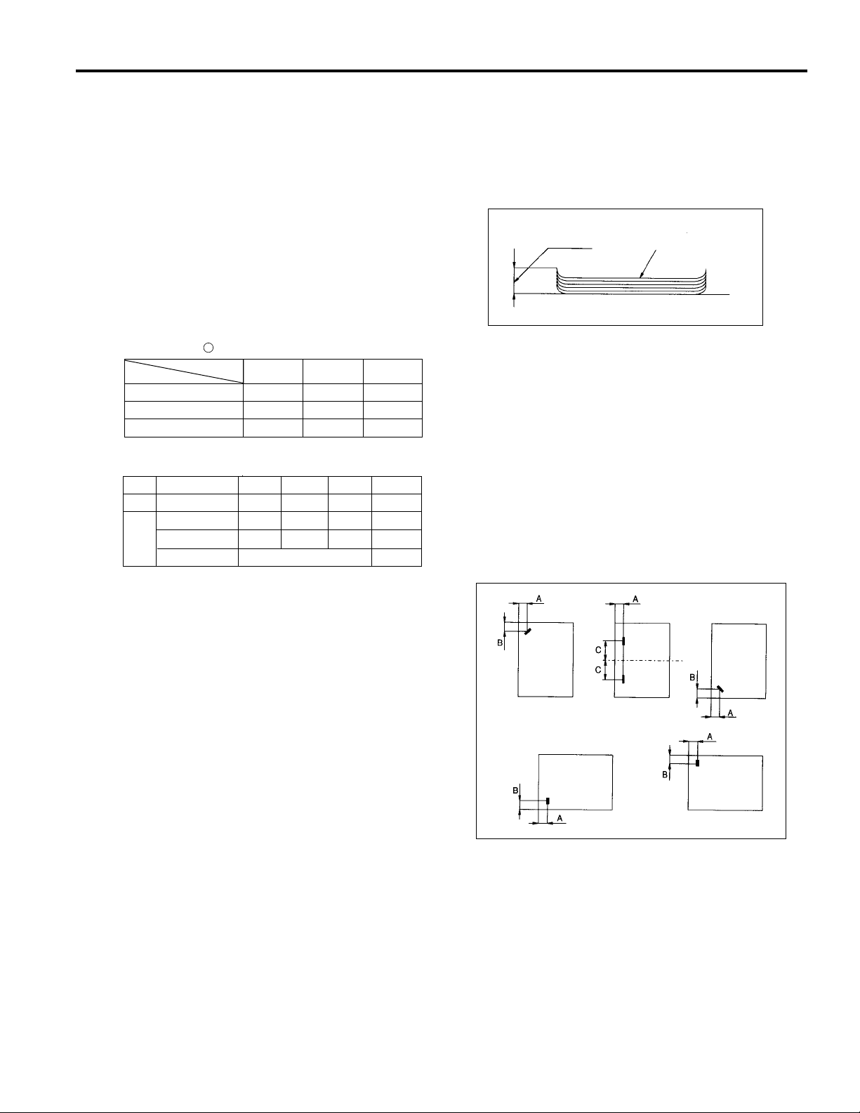
curling: 10 mm maximum
Curling
Copy paper (5 sheets)
Offset amount: 30 mm (offset/group mode)
Stapler Kit
No. of
copies
stapled : 50 maximum (22 lb. fine quality
paper, thickness 5 mm max)
Staple
position: A = 8 mm (±3 mm adjustable)
B = 10 mm (±3 mm adjustable)
C = 90 mm (±4 mm adjustable)
Stapler
capacity: 5000 staples/cartridge
Note1: The above numbers apply for same-size
paper (22 lb., standard paper) stacked
continuously.
Note2: Small sizes: 5.5 x 8.5R
Middle sizes: 8.5 x 11, 8.5 x 11R
Large sizes: 11 x 17R, 8.5 x 14R
Special paper: Other than standard paper
(thin paper, thick paper,
blueprint master
OHP film etc.)
Note3: The maximum capacity (500 or 300
sheets) should not be exceeded.
1
Page 10

FS-109
Particulars of Machine
Power
source:
Max. power
consumption: 100 VA
Weight: Approximately 81 lb. (with pedestal)
Machine
dimensions: Width 10.4 in.
24 V DC / 5 V (supplied from main body)
Depth 23.6 in.
Height 24.5 in.
Maintenance and Life
Maintenance: Same as the main body
Operating Environment
Temperature: 50°F to 86°F
Humidity: 10% to 80% RH
Note: The contents of this manual may be changed
without prior notice.
2
Page 11
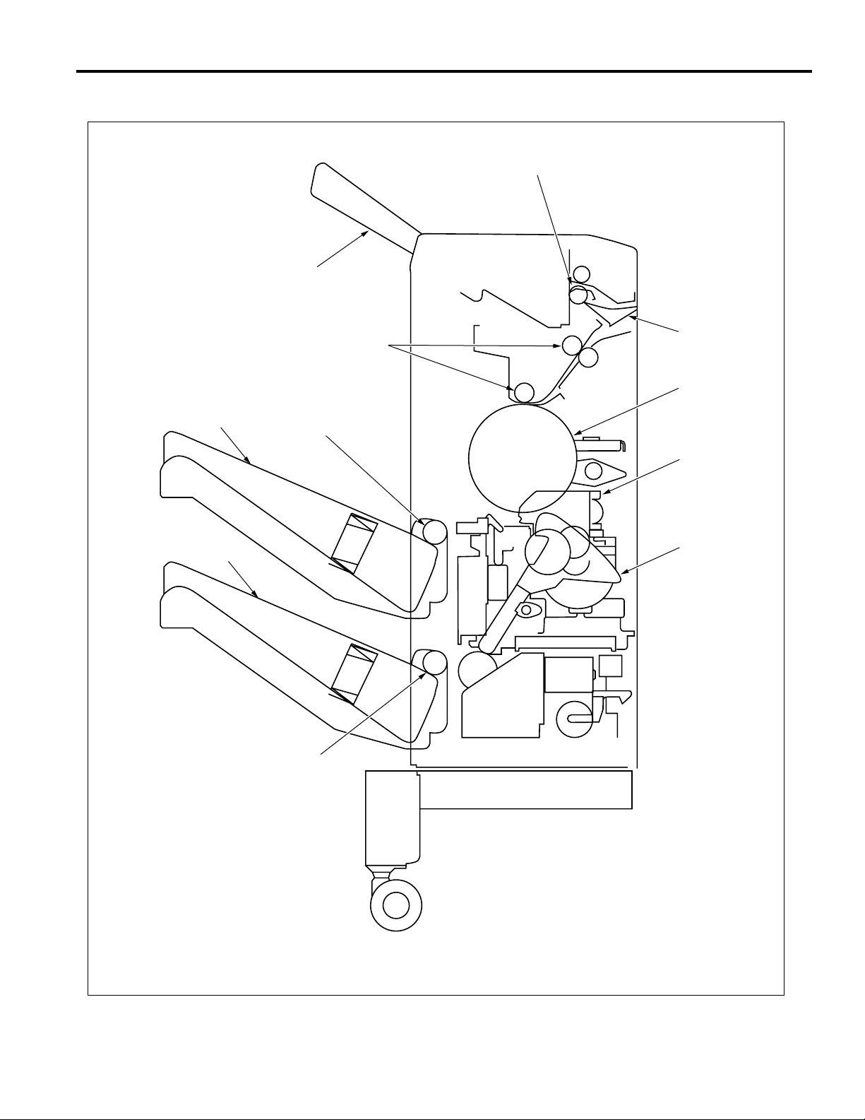
CENTER CROSS-SECTIONAL VIEW
Paper exit roller
Tray 1
FS-109
Tray 2
Tray 3
Conveyance rollers
Switching gate
Conveyance drum
Paper exit roller (A)
Stapler unit
Exit lever
Paper exit roller (A)
3
Page 12
FS-109
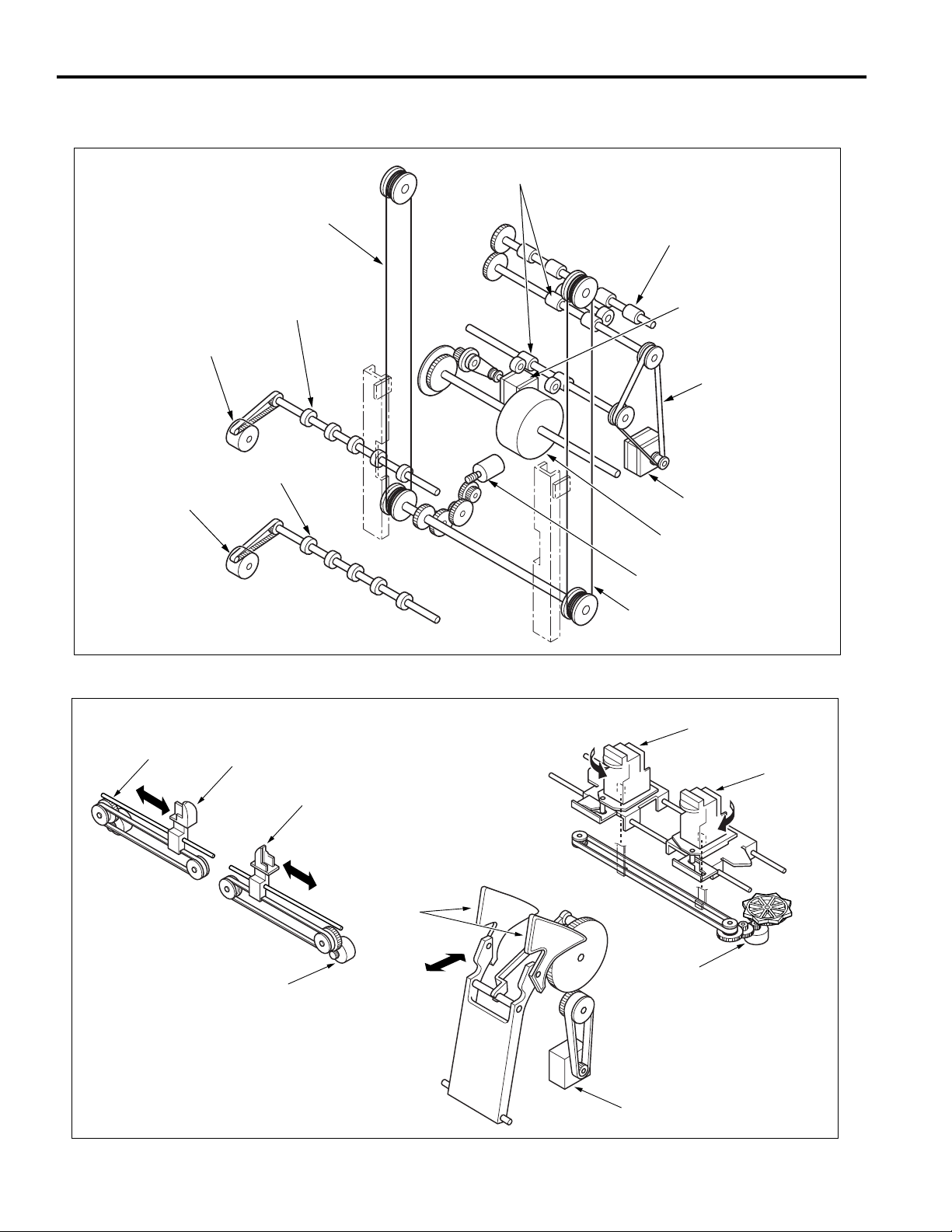
DRIVE SYSTEM DIAGRAM
Paper Conveyance System Drive
Conveyance rollers
Tray 2 motor (M810)
Tray 3 motor (M811)
Lift wire (rear)
Paper exit roller (A)
Paper exit roller (A)
Paper exit roller
Conveyance
drum drive motor (M807)
Timing belt
Conveyance motor (M801)
Conveyance drum
Tray up/down motor (M804)
Lift wire (front)
Stapler Unit System Drive
Alignment motor
(rear)(M808)
Alignment plate
(rear)
Alignment plate
(front)
Alignment motor
(front)(M809)
Stapler unit (rear)
Stapler unit (front)
Exit lever
Stapler movement
motor (M806)
Paper exit motor (M805)
4
Page 13
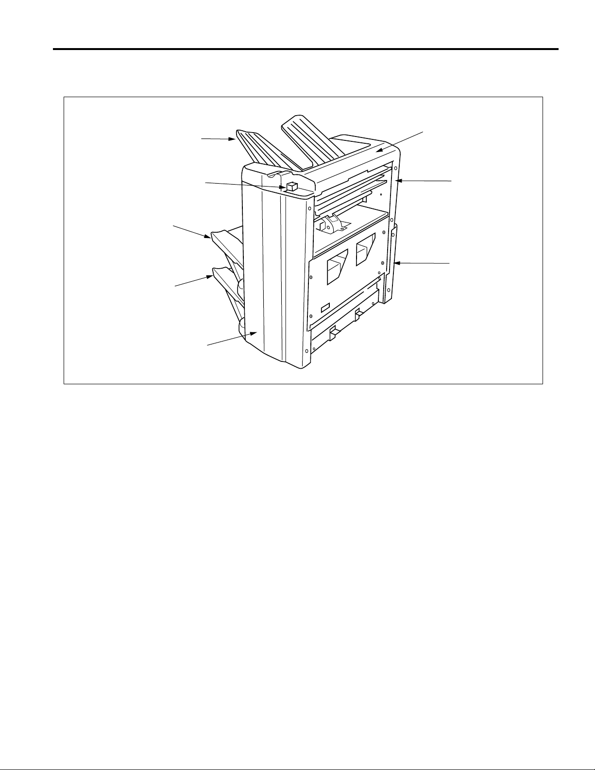
EXTERNAL SECTION
Composition
FS-109
Tray 1
Release lever
Tray 2
Tray 3
Front cover
Top cover
Upper rear cover
Rear cover
5
Page 14
FS-109
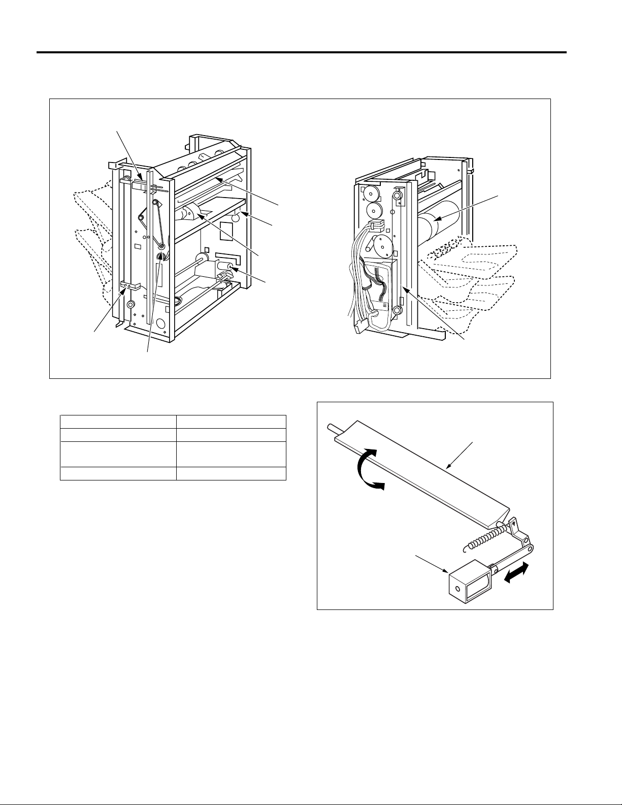
CONVEYANCE SECTION
Composition
Gate SD
Lift wire
Mechanisms
Mechanisms Methods
Paper path switching *1
Paper conveyance *2
Tray lift (up/down) *3
Conveyance motor
Switching gate
Conveyance roller
Conveyance drum
Wire drive (Lift wire)
Switching gate
Conveyance
drum motor
Conveyance
drum
Tray up/down
motor
Conveyance
drum
Lift wire
Switching gate
*1: Paper path switching
The paper exited from the fixing unit in the main body
passes through the switching gate which sends it to
tray 1 or tray 2/3. The switching gate is operated by
the on/off state of the gate SD (SD801).
Gate SD
6
Page 15
FS-109
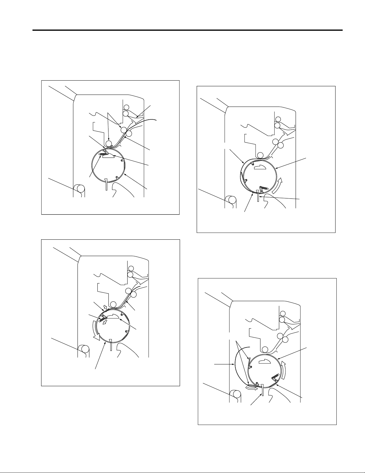
*2: Paper Conveyance
When the paper has been switched to tray 2/3 by the
switching gate, the conveyance roller conveys it to
the conveyance drum until it enters the grip plate on
the circumference of the drum.
Switching
Conveyance
rollers
Grip plate
Spring
gate
Paper
Cam
Conveyance
drum
When the rotation speed of the drum increases, the
paper is pushed out and separated from the
conveyance drum. When the grip plate on the
conveyance drum reaches the paper exit position,
the paper hits a stopper and is separated from the
grip plate.
Paper
Conveyance
drum
Stopper
The grip plate closes due to the force of a cam and
spring arrangement and grasps the paper.
Grip plate
Spring
Conveyance drum
Paper
Cam
Grip plate
Behind the grip plate on the drum circumference,
there are two alignment plates. When these reach
the paper exit position, their own weight causes them
to open, and the rubber section at the plate tip aligns
the paper against the stopper.
Alignment plates
Conveyance
drum
Paper
Grip plate
Stopper
7
Page 16
FS-109
The grip plate and alignment plates on the
conveyance drum do not use electrical control, they
operate only through the rotation of the drum. (The
grip plate is driven by the drum via a cam
arrangement, and the alignment plates are driven by
the centrifugal force and their own weight.)
The conveyance drum and conveyance rollers are
controlled electrically by conveyance drum motor
(M807) and conveyance motor (M801).
*3: Tray lift
The paper exit position for the paper sent to tray 2/3
is fixed. Switching between tray 2 and tray 3 is
carried out by changing the tray position with the tray
lift (up/down) mechanism.
The tray lift mechanism is driven by the tray up/down
motor (M804) whose driving force is transmitted to the
tray by a wire arrangement.
Lift wire
Tray 2
Tray up/down motor
Tray 3
8
Page 17
FS-109
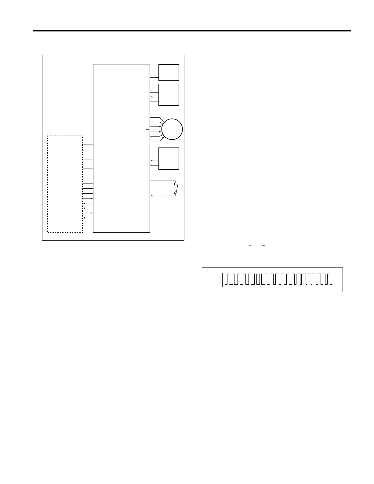
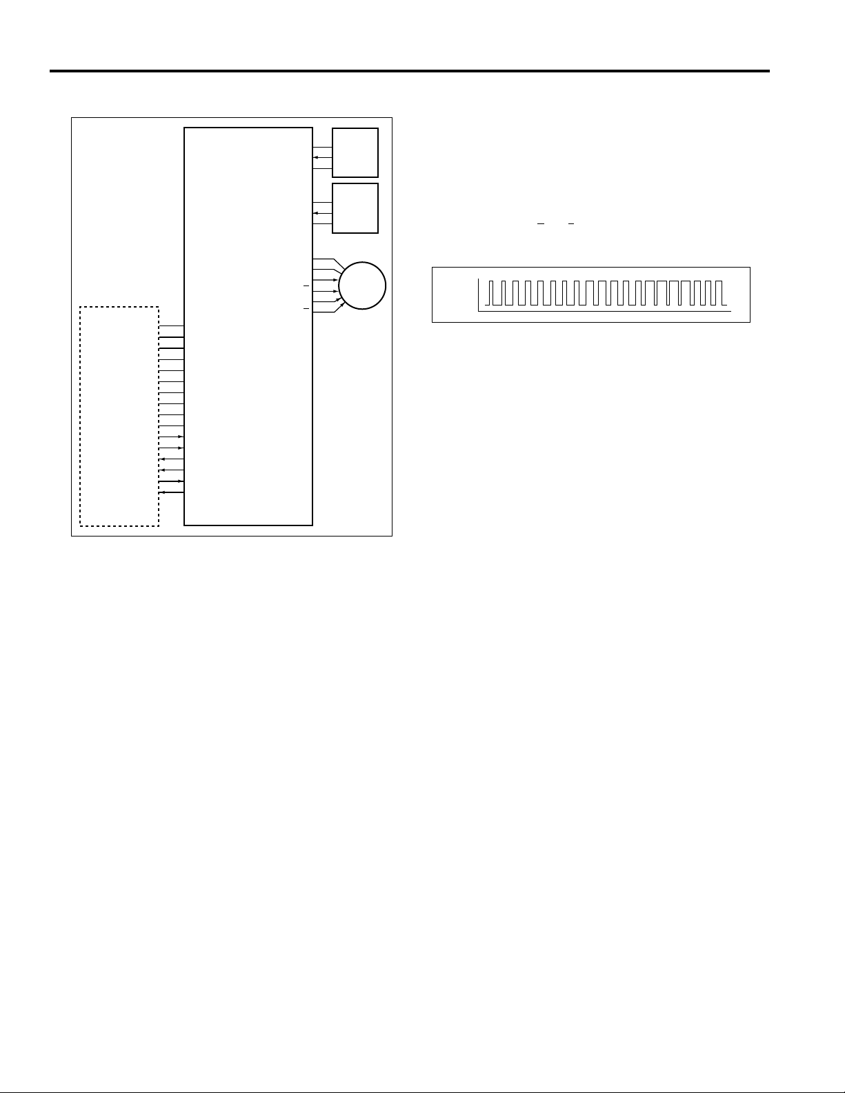
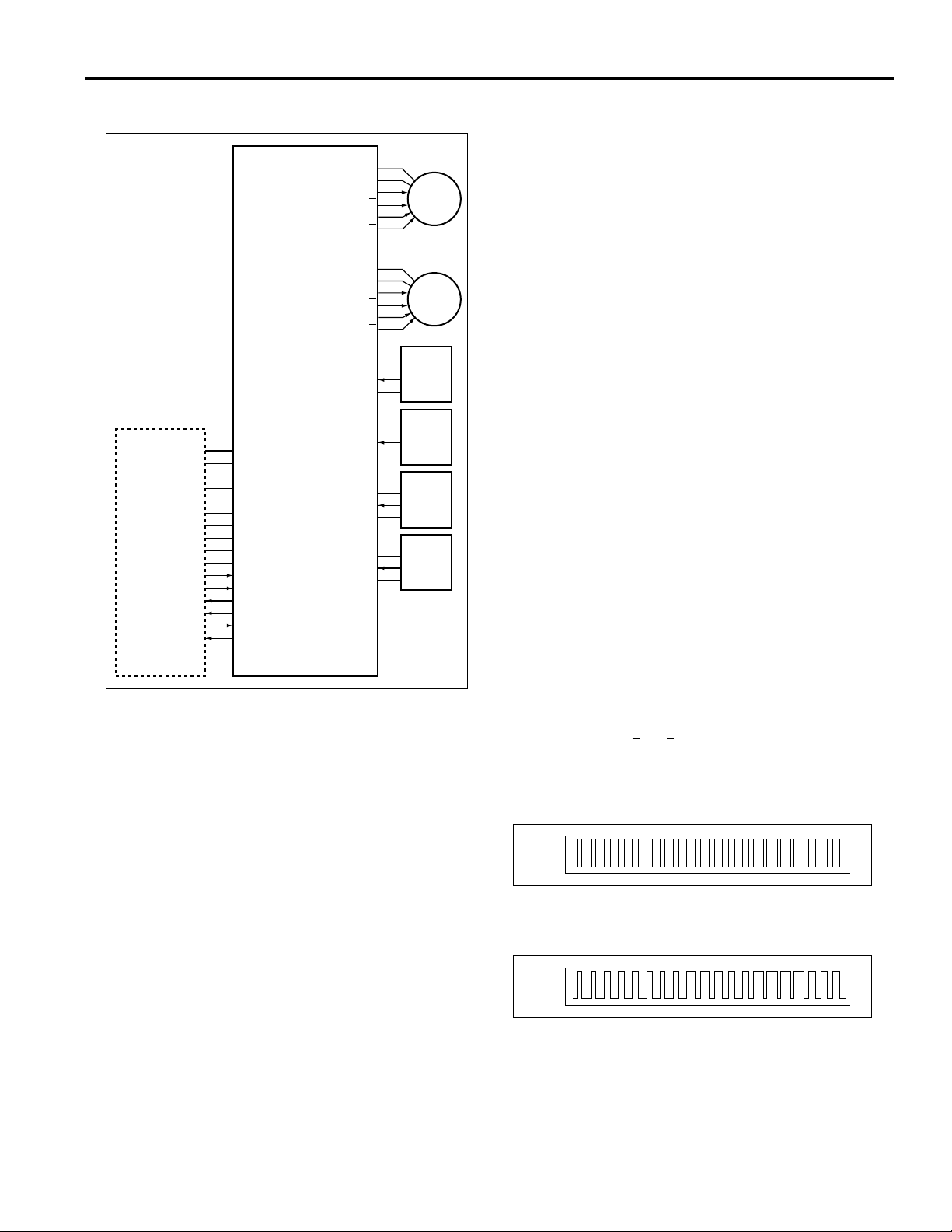
Conveyance Motor (M801) Control
24V
SD801 DRV
VCC
PS803IN
GND
24V
24V
M801 DRVA
M801 DRVA
M801 DRVB
SGND
SGND
PGND
PGND
PGND
M TxD
M REQ
M ACK
MAIN BODY
5V
5V
24V
24V
24V
S ACK
M RxD
S REQ
FNSCB
M801 DRVB
VCC
PS802IN
GND
24VOUT
24VIN
SD801
PS803
M801
PS802
MS801
2. Signals
a. Input signals
(1) PS802IN (PS802 to FNSCB)
Paper detection signal at the paper exit section
entrance of the tray 2 and tray 3 side.
[L]: Paper is not detected
[H]: Paper is detected
(2) PS803IN (PS803 to FNSCB)
Paper detection signal at the paper exit section
entrance of the tray 1.
[L]: Paper is not detected
[H]: Paper is detected
(3) 24VIN (MS801 to FNSCB)
Power supply line for various loads. When finisher is
in mechanical contact with main body, 24 V DC is
supplied to finisher.
(4) M TxD (MAIN BODY to FNSCB)
Serial data line for transmitting operation status
information from control board in main body to
finisher.
(5) M REQ (MAIN BODY to FNSCB)
Send request signal from main body to finisher.
(6) M ACK (MAIN BODY to FNSCB)
Send enable signal from main body to finisher.
Paper exit conveyance takes place as a result of the
transmission of the drive force of motor M801
(conveyance) to the paper exit rollers and conveyance
rollers. The paper conveyance path is switched between
tray 1 or tray 2/3 by solenoid SD801 (gate).
M801 and SD801 are controlled by the FNSCB (FNS
control board).
1. Operation
a. Gate switching operation
Normally, SD801 is OFF and the gate allows paper to
exite to tray 2/3. When tray 1 is selected as the paper
exit tray, SD801 goes ON, the gate is switched, and
the paper is conveyed to tray 1.
b. Conveyance operation
M801 is turned ON and OFF in conjunction with the
copy operation of the main body. During operation of
the main body, the M801 rotates constantly, enabling
paper conveyance at any time.
When paper has been conveyed to tray 2/3, the
status of the PS802 (drum entrance) and main body
PS1 (paper exit) causes the M801 to be switched
from low speed to high speed. The high-speed
activation signal and the rotation speed depend on
the paper size.
b. Output signals
(1) M801 DRV A, A, B, B (FNSCB to M801)
M801 ON/OFF drive signal
24V
0V
(2) SD801 DRV (FNSCB to SD801)
SD801 ON/OFF drive signal
[L]: SD801 ON
[H]: SD801 OFF
(3) M RxD (FNSCB to MAIN BODY)
Serial data line for transmitting operation status information
from finisher to main body CB (control board).
(4) S REQ (FNSCB to MAIN BODY)
Send request signal from finisher to main body.
(5) S ACK (FNSCB to MAIN BODY)
Send enable signal from finisher to main body.
9
Page 18
FS-109
Conveyance Drum (M807) Control
VCC
PS801IN
GND
VCC
PS802IN
GND
24V
24V
M807 DRVA
M807 DRVA
M807 DRVB
SGND
SGND
5V
5V
PGND
PGND
PGND
24V
24V
24V
M TxD
M REQ
M ACK
S ACK
M RxD
S REQ
M807 DRVB
PS801
PS802
M807
2. Signals
a. Input signal
(1) PS801IN (PS801 to FNSCB)
Encoder slit detection signal
[L]: Slit is not detected
[H]: Slit is detected
b. Output signal
(1) M807 DRV A, A, B, B (FNSCB to M807)
M807 ON/OFF drive signal
24V
0V
MAIN BODY
FNSCB
The paper that has been sent to tray 2/3 is exited into the
respective tray by the conveyance drum. The conveyance
drum is driven by M807 (conveyance drum) which is
controlled by the FNSCB (FNS control board).
1. Operation
a. Conveyance operation
When PS802 (drum entrance) detects the leading
edge of the paper and goes ON, M807 is turned ON
after the specified time, and the conveyance drum
starts to rotate.
To convey one sheet of paper, the M807 is switched
through a predetermined sequence of three speeds.
When the conveyance drum reaches the standby
position, the motor is switched OFF.
During this time, the drum makes one revolution
which includes gripping, conveying, and releasing
the paper.
b. M807 speed control
When the conveyance drum rotation pulses reach a
predetermined number, the rotation speed is
changed.
10
Page 19
FS-109
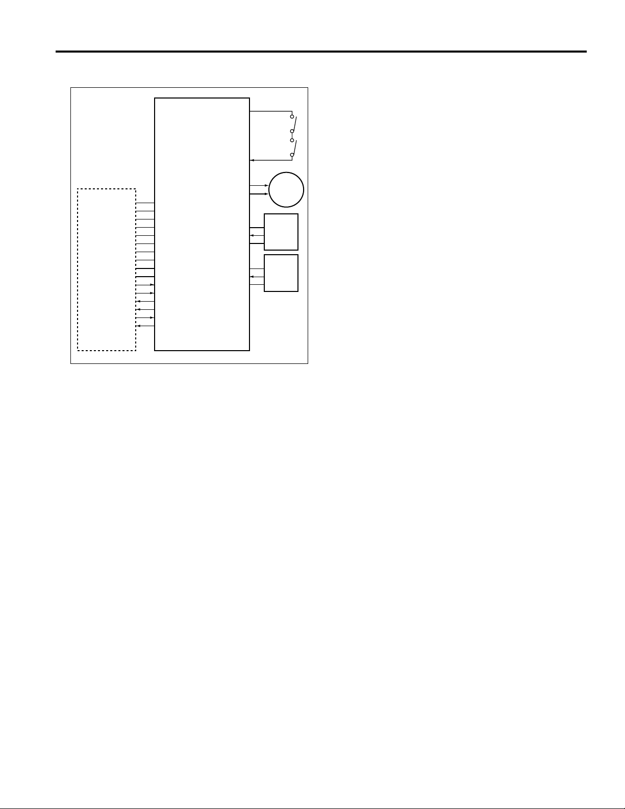
Tray Up/Down (M804) Control
24VOUT
MS802
MS803
24VIN
M804 DRV 1
SGND
SGND
PGND
PGND
PGND
M TxD
M REQ
M ACK
MAIN BODY
5V
5V
24V
24V
24V
S ACK
M RxD
S REQ
FNSCB
M804 DRV 2
VCC
PS805IN
GND
VCC
PS806IN
GND
The paper exit position of the conveyance drum is always
fixed, and tray switching is carried out by raising or
lowering tray 2/3.
The up/down motion is achieved by transmitting the
driving force of motor M804 (tray up/down) to the lift wires
connected to each tray. This operation is controlled by the
FNSCB (FNS control board).
M804
PS805
PS806
1. Operation
Normally, the paper exit position of the conveyance
drum is aligned with tray 2. Therefore no lift operation
is carried out when tray 2 is selected.
a. Upward movement
When tray 3 is selected as paper exit tray and PS806
(traylower limit) is ON, M804 (tray up/down) goes ON
(forward rotation). Tray 2 and tray 3 are then raised
simultaneously.
When the upward movement causes tray 2 to switch
PS805 (tray upper limit) to ON, M804 goes OFF and
the upward movement stops. Tray 3 is now aligned
with the paper exit position of the conveyance drum.
b. Downward movement
When tray 2 is selected as paper exit tray and PS805
is ON, M804 goes ON (reverse rotation). Tray 2 and
tray 3 are then lowered simultaneously.
When the downward movement causes tray 3 to
switch PS806 to ON, M804 goes OFF and the
upward movement stops. Tray 2 is now aligned with
the paper exit position of the conveyance drum.
c. Tray squeeze prevention
During tray upward or downward movement, if a
foreign object is caught between the tray and the
finisher unit, MS802 (up/down (upper)) or MS803
(up/down (lower)) will mechanically go OFF, causing
the power supply line of M804 to be cut off.
11
Page 20

FS-109
2. Signals
a. Input signals
(1) PS805IN (PS80 to FNSCB)
Tray 2 upper limit detection signal.
[L]: Upper limit is not detected
[H]: Upper limit is detected
(2) PS806IN (PS806 to FNSCB)
Tray 3 lower limit detection signal.
[L]: Lower limit is not detected
[H]: Lower limit is detected
(3) 24VIN (MS802/MS803 to FNSCB)
Power supply line for M804 (tray up/down). Forcibly
interrupted when a foreign object is caught between
tray and finisher unit.
b. Output signal
(1) M804 DRV 1, 2 (FNSCB to M804)
M804 drive signals.
M804 rotation direction is controlled by switching the
current direction of these two signals.
State M804 DRV 1 M804 DRV 2
Upward movement
Downward movement
Stop
L
L
H
L
H
H
12
Page 21
PAPER EXIT/STAPLER UNIT SECTION
Composition
FS-109
Paper exit rollers (A)
Tray 2 motor
Tray 3 motor
Alignment plate (front)
Tray 2/3
Stapler unit (front)
Alignment motor (front)
Exit levers
Stapler movement motor
Stopper
Stapler
unit (rear)
Paper exit motor
Mechanisms
Mechanisms Methods
Paper alignment *1
Paper exit *2
Paper stacking *3
Stapler unit movement
Staple accident prevention *4
*1: Paper alignment
The paper being conveyed by the conveyance drum
is aligned by the alignment plates. Separately driven
guides are provided for front and rear, to allow
independent movement and asymmetrical operation
in shift mode.
The alignment plates are driven by the alignment motor
(front) (M809) and alignment motor (rear) (M808).
Separate guides for front and rear
Exit lever
Paper exit roller (A)
Stapler unit movement motor
Shutter cover
Alignment motor (rear)
Alignment plate (rear)
Alignment plate (front)
Alignment motor (front)
13
Page 22
FS-109
Exit levers
*2: Paper exit
The paper being supplied by the conveyance drum is
conveyed to the stapling position, regardless of
whether stapling will be carried out or not. If stapling
is enabled, the stapled stack is exited to tray 2 or 3
after stapling. If stapling is not enabled, each sheet is
exited individually to tray 2 or 3.
This movement is performed by the exit levers which
are driven by the paper exit motor (M805).
Paper exit motor
Tray 2 motor
Tray 3 motor
Paper exit roller (A)
*4: Staple accident prevention
A shutter cover is provided to prevent the user from
inadvertently inserting a finger etc. into the stapler. The
shutter cover is driven by the shutter SD (SD802) which
is ON during stapler operation and during stapler unit
movement. The shutter cover blocks the clearance
between the paper exit tray and the stapler unit.
*3: Paper stacking
A spring arrangement in the bottom of tray 2 and tray
3 lifts the bottom plate up, so that it always is in direct
contact or not more than 3 mm away from the paper
exit roller assembly.
[ Operation in through mode ]
The paper is stacked on the tray by the movement of
the exit lever and the rotation of the paper exit roller
(A) of each tray.
When the paper exit roller (A) turns, the tip of the
paper is grasped by the rollers and is stacked under
the rollers.
[ Operation in offset mode ]
The paper is offset by the alignment plates (front/
rear), and is stacked on the tray by the movement of
the exit lever and the rotation of the paper exit roller
(A) of each tray.
By repeating this action, the tip of the paper is
grasped by the rollers and is stacked under the
rollers.
Tray 2
Shutter SD
Paper exit roller (A)
Conveyance
drum
Spring
Stapler
unit
Exit lever
Shutter
cover
14
Page 23
FS-109
24V
0V
24V
0V
Paper Alignment Control
24V
24V
M808 DRV A
M808 DRV A
M808 DRV B
M808 DRV B
24V
24V
M809 DRV A
M809 DRV A
M809 DRV B
M809 DRV B
5VDC
PS815IN
GND
5VDC
SGND
SGND
PGND
PGND
PGND
M TxD
M REQ
M ACK
MAIN BODY
5V
5V
24V
24V
24V
S ACK
M RxD
S REQ
FNSCB
PS816IN
GND
5VDC
PS802IN
GND
5VDC
PS804IN
GND
The paper exited by the conveyance drum is aligned on
the center of the respective exit tray by the alignment
plates driven by the M808 (alignment (rear)) and M809
(alignment (front)). M808 and M809 are controlled by the
FNSCB (FNS control board).
1. Operation
a. Non-shift alignment operation
The alignment plate (front) and alignment plate (rear)
work symmetrically, with the tray center serving as
the reference point. The guides repeat the alignment
and release pattern. The rotation direction of M809
and M808 is therefore always opposite.
The ON timing of M809 and M808 is referenced to
the ON/OFF state of PS802 (drum entrance) or
PS804 (paper through detect). Which sensor is used
depends on the paper size.
M808
M809
PS815
PS816
PS802
PS804
b. Shift alignment operation
During the first alignment operation, the alignment
plate (front) and alignment plate (rear) are front and
rear symmetric with respect to operation as
reference with the center of the tray and paper is
exited.
During the next alignment operation, the alignment
plate (front) and alignment plate (rear) are not front
and rear symmetric with respect to operation as
reference with the center of the tray and paper is
exited at the position shift to the first copy.
From now on, these operation are repeated.
The ON/OFF timing of M809 and M808 is the same
as that of the non-shift alignment operation.
c. Staple mode operation
In staple mode, M809 and M808 perform release
operation after stapling is completed. The ON/OFF
timing is based on the OFF timing of the stapler motor
that last completed a stapling operation (M802 or M803).
2. Signals
a. Input signals
(1) PS815IN (PS815 to FNSCB)
Home position detection signal for alignment plate
(front).
[L]:Alignment plate is not in home position
[H]:Alignment plate is in home position
(2) PS816IN(PS816 to FNSCB)
Home position detection signal for alignment plate (rear).
[L]:Alignment plate is not in home position
[H]:Alignment plate is in home position
b. Output signals
(1) M808 DRV A, A, B, B (FNSCB to M808)
M808 ON/OFF drive signal
(2) M809 DRV A, A, B, B (FNSCB to M809)
M809 ON/OFF drive signal
15
Page 24

FS-109
Paper Exit (M805) Control
24V
24V
M805 DRV A
M805 DRV A
M805 DRV B
SGND
SGND
PGND
PGND
PGND
M TxD
M REQ
M ACK
MAIN BODY
5V
5V
24V
24V
24V
S ACK
M RxD
S REQ
FNSCB
M805 DRV B
VCC
PS813IN
GND
VCC
PS804IN
GND
When the alignment or stapling operation is completed, the
paper is pushed out to tray 2 or tray 3 by the exit levers. The
levers are driven by M805 (paper exit) via a set of gears.
Operation is controlled by the FNSCB (FNS control board).
M805
PS813
PS804
2. Signals
a. Input signal
(1) PS813IN (PS813 to FNSCB)
Home position detection signal for exit lever.
[L]: Exit lever is not in home position
[H]: Exit lever is in home position
b. Output signal
(1) M805 DRIVE A, A, B, B (FNSCB to M805)
M805 ON/OFF drive signal
24V
0V
1. Operation
a. Non-stapling mode operation
The drive gear for the exit levers is controlled using
the home position detected by PS813 (paper exit
motor HP).
When PS804 (paper through) detects the paper
leading edge and goes ON, M805 goes ON for the
specified time and drives the exit levers. This causes
PS813 to go OFF.
The exit levers are connected to the circumference of
the drive gear. Within one rotation of the gear, the
paper is pushed out (forwarding motion) and
returned to the standby position (return motion).
When PS813 goes ON, the exit levers have returned
to the standby position and M805 is turned OFF.
b. Stapling mode operation
In stapling mode, when the stapler motor (M802 or
M803) that has last finished to operate goes OFF,
M805 goes ON for the specified time and drives the
exit levers. Other operations are the same as for nonstapling mode.
16
Page 25

FS-109
24V
0V
24V
0V
Paper Stacking Control
24V
24V
M810 DRV A
M810 DRV A
M810 DRV B
M810 DRV B
24V
24V
M811 DRV A
M811 DRV A
M811 DRV B
SGND
SGND
PGND
PGND
PGND
M TxD
M REQ
M ACK
MAIN BODY
5V
5V
24V
24V
24V
S ACK
M RxD
S REQ
FNSCB
M811 DRV B
VCC
PS807IN
GND
VCC
PS809IN
GND
The paper exited to tray 2 or tray 3 is placed on top of the
paper exit rollers of the respective tray. The drive force of
motor M810 (tray 2) or M811 (tray 3) is used to operate the
rollers and stack the paper on the tray.
M810 and M811 operation is controlled by the FNSCB
(FNS control board).
M810
M811
PS807
PS809
b. Tray auto-switching control
When copying is carried out with tray 2 or tray 3
specified as output tray and the specified tray
becomes full, causing PS807 or PS809 to become
ON, the output tray is automatically switched to the
other tray.
This operation is also valid if tray 1 is specified as the
output tray. The output tray will be switched to tray 2
or tray 3. Normally, tray 2 will be selected. If it is full,
tray 3 will be selected. Switching from tray 2 or tray 3
to tray 1 is not possible.
2. Signals
a. Input signals
(1) PS807IN (PS807 to FNSCB)
Tray 2 stack-full detection signal
[L]: Stack full condition not detected
[H]: Stack full condition detected
(2) PS809IN (PS809 to FNSCB)
Tray 3 stack-full detection signal
[L]: Stack full condition not detected
[H]: Stack full condition detected
b. Output signals
(1) M810 DRV A, A, B, B (FNSCB to M810)
M810 ON/OFF drive signal
(2) M811 DRV A, A, B, B (FNSCB to M811)
M811 ON/OFF drive signal
1. Operation
a. Paper stacking control
When M805 (paper exit) goes ON, M810 (tray 2) or
M811 (tray 3) are set to ON after the specified time.
When M805 goes OFF, M810 or M811 are set to OFF
after the specified time. While the motor is ON, the
rollers of the tray are driven and the paper that was
placed on the rollers is stacked.
The stacking section of the tray is pushed up by a
spring. When the maximum allowable number of sheets
has been stacked, the stacking section contacts the
bottom of the tray and PS807 (tray 2 full-stack detect) or
PS809 (tray 3 full-stack detect) goes ON.
When PS807 or PS809 are ON, no copy operation
will be carried out when the respective tray is
selected.
17
Page 26

FS-109
Stapler Movement (M806) Control
24V
24V
M806 DRV A
M806 DRV A
M806 DRV B
SGND
SGND
PGND
PGND
PGND
M TxD
M REQ
M ACK
MAIN BODY
5V
5V
24V
24V
24V
S ACK
M RxD
S REQ
FNSCB
M806 DRV B
VCC
PS814IN
GND
24V
24VIN
The position of the stapler units at the front and rear with
respect to the paper is adjusted using the driving force of
the M806(stapler movement). Operation of M806 is
controlled by the FNSCB (FNS control board).
1. Operation
Normally, the stapler units are stationary, positioned so
that the stapling is carried out parallel to the paper
edge. This position is detected by PS814 (stapler unit
HP).
When the stapling position is changed according to a
command from the main body, M806 goes ON and
the two stapler units at the front and rear are moved
simultaneously. The M806 OFF timing is controlled
using the number of drive step from when PS814
went OFF.
M806
PS814
MS804
Stapler Control
M802 DRV 1
M802 DRV 2
VCC
PS820IN
PS821IN
PS822IN
GND
M803 DRV 1
M803 DRV 2
VCC
PS817IN
PS818IN
PS819IN
GND
SGND
SGND
PGND
PGND
PGND
M TxD
M REQ
M ACK
MAIN BODY
5V
5V
24V
24V
24V
S ACK
M RxD
S REQ
FNSCB
24VOUT
24VIN
24V
SD802 DRV
Stapling is carried out by driving M802 (stapler (rear)) and
M803 (stapler (front)). Operation of M802 and M803 is
controlled by the FNSCB (FNS control board).
The maximum number of sheets for stapling and the
operation to be carried out when the number is exceeded
can be set with 25 mode of the main body. For details,
refer to the adjustment section of the main body
M802
M803
MS804
SD802
2. Signals
a. Input signals
(1) PS814IN (PS814 to FNSCB)
Home position detection signal for stapler unit
[L]: Stapler unit is in home position
[H]: Stapler unit is not in home position
(2) 24VIN (MS804 to FNSCB)
Power supply line for M802 (stapler (rear)), M803
(stapler (front)), and M806. Forcibly interrupted when
the shutter is raised.
b. Output signal
(1) M806 DRV A, A, B, B (FNSCB to M806)
M806 ON/OFF drive signal
24V
0V
18
Page 27

FS-109
1. Operation
a. Stapling operation
M803 (stapler (front)) goes ON when the last paper
alignment operation is completed, and goes OFF
when PS817 (stapler HP (front)) goes ON.
This causes the front side of the paper to be stapled.
When stapling at two locations is carried out, M802
(stapler (rear)) goes ON after the specified time,
measured from the point when M803 goes ON. It
goes OFF when PS820 (stapler HP (rear)) goes ON.
b. Shutter control
During stapler unit movement and during stapling
operation, the SD802 (shutter) is ON, causing the
shutter to block the clearance between the paper exit
tray and the stapler unit.
c. No-staple detection
The front and rear stapler units are each equipped
with a PS818, PS821 (no stapler (front), (rear)).
When staples have run out and the no staple
condition is detected, a message is shown on the
display of the main body.
2. Signals
a. Input signals
(1) PS817IN (stapler unit (front) to FNSCB)
Home position detection signal for M803
[L]: Home position is detected
[H]: Home position is not detected
(2) PS818IN (stapler unit (front) to FNSCB)
Stapler unit (front) no-staple detection signal.
[L]: No-staple condition is detected
[H]: No-staple condition is not detected
(3) PS820IN (stapler unit (rear) to FNSCB)
Home position detection signal for M802
[L]: Home position is detected
[H]: Home position is not detected
(4) PS821IN (stapler unit (rear) to FNSCB)
Stapler unit (rear) no-staple detection sensor signal
[L]: No-staple condition is detected
[H]: No-staple condition is not detected
(5) PS819IN (stapler unit (front) to FNSCB)
[L]: stapler unit (front) tion is detected
[H]: No-staple condition is not detected
(6) PS822IN (stapler unit (rear) to FNSCB)
stapler unit (rear) no-staple sensor signal at the
stapling position.
[L]: No-staple condition is detected
[H]: No-staple condition is not detected
b. Output signals
(1) M802 DRV 1, 2 (FNSCB to stapler unit (rear))
M802 drive signals.
M802 rotation direction is controlled by switching the
current direction of these two signals.
(2) M803 DRV 1, 2 (FNSCB to stapler unit (front))
M803 drive signals.
M803 rotation direction is controlled by switching the
current direction of these two signals.
(3) SD802 DRV (FNSCB to SD802)
SD802 ON/OFF drive signal.
[L]: SD802 ON
[H]: SD802 OFF
19
Page 28

FS-109
OTHER CONTROL FUNCTIONS
Power-on Operation
When the main body SW2 (sub power) is set to ON,
the finisher performs the following initialization
sequence.
1. SD802 (shutter) goes ON and the shutter cover closes.
2. M808 (alignment (rear)) and M809 (alignment (front))
go ON and the alignment plates (front/rear) perform
home position search.
3. M807 (conveyance drum) goes ON and the conveyance drum performs home position search.
4. M806 (stapler movement) goes ON and the stapler unit
moves to the standby position.
5. SD802 goes OFF and the shutter cover opens.
6. M805 (paper exit) goes ON and the exit lever is driven
for one operation.
7. Lower limit position detection for tray 2 and tray 3 is
carried out. If PS806 (tray lower limit) does not go ON,
M804 (tray up/down) goes ON, causing tray 2 and tray
3 to move downward.
20
Page 29

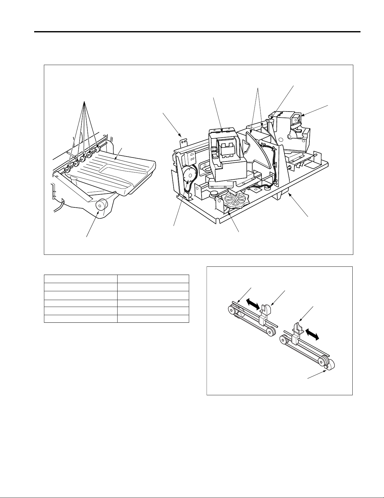
DISASSEMBLY AND REASSEMBLY
FS-109
Caution: Be sure that the power cord of the
main body is unplugged from the
power outlet.
Replacing the Tray 2/3 Paper Exit Roller
Unit
Before replacing the paper exit roller unit for tray 3,
move tray 2 to the top. (See 2. "Raising and
Lowering the Tray".)
a. Procedure
(1) Remove the two set screws, and remove the connector
cover.
Set screws
Connector cover
Raising and Lowering the Tray
a. Raising procedure
(1) Start the main body in the 47 mode while referring to the
main body manual (Field Service volume).
(2) Enter the following codes.
Input/output check code: 70
Multi code: 16
Note: Finalize each entered code by pressing
the P button
(3) Press the Start button, and the tray starts to rise. When
the tray reaches the position at which you wish to stop
it, press the Stop/Clear button.
b. Lowering procedure
(1) Start the main body in the 47 mode while referring to
main body manual (Field Service volume).
(2) Enter the following codes.
Input/output check code: 70
Multi code: 15
Note: Finalize each entered code by pressing
the P button.
(3) Press the Start button, and the tray starts to fall. When
the tray reaches the position at which you wish to stop
it, press the Stop/Clear button.
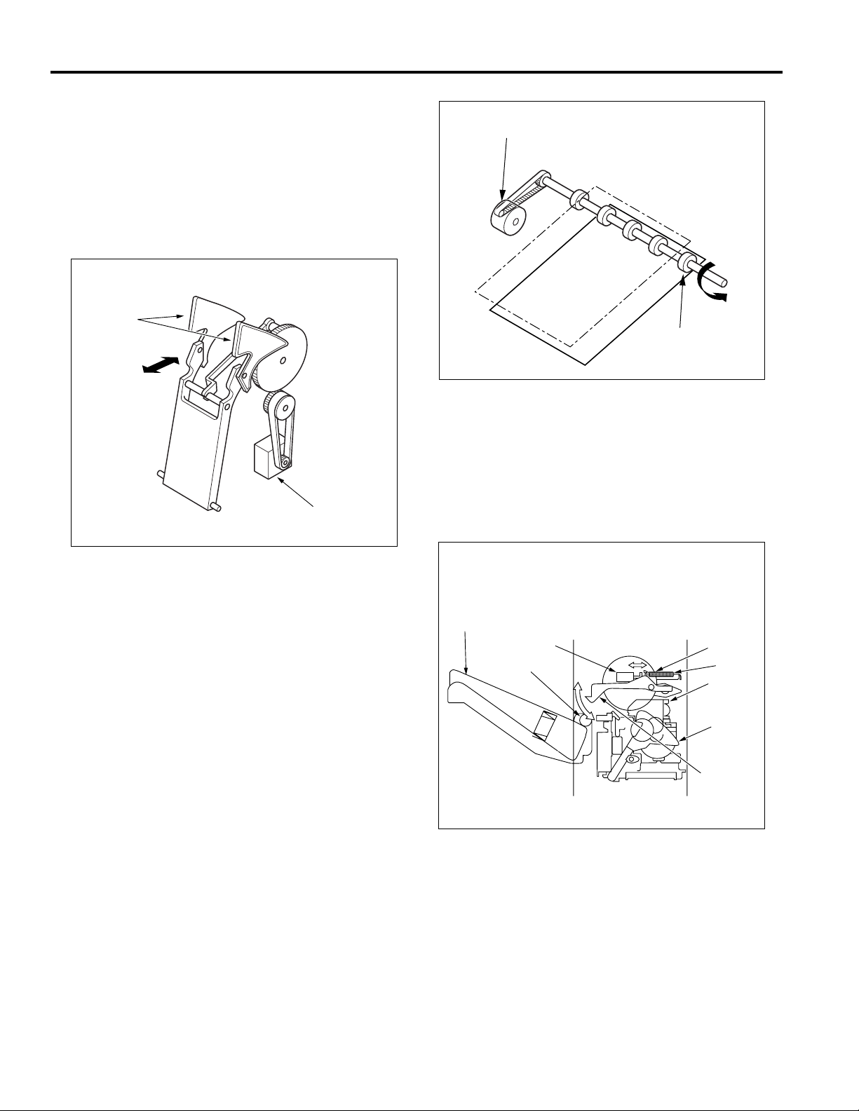
(2) Remove the left and right stop rings and bearings, then
remove the paper exit roller unit.
Stop ring
Paper exit roller unit
Bearing
(3) Install the new roller unit in the opposite sequence to
removal.
Stop ring
Bearing
21
Page 30

FS-109
Removing and Reinstalling Tray 2/3
a. Procedure
(1) Remove the two set screws, and remove the connector
cover.
(2) Disconnect the two connectors (CN728 and 751: Tray
2 / CN729 and 752: Tray 3).
(3) Remove the set screw, and remove the stopper.
Set screw
Stopper
Connector
(CN 728)
Connector
(CN 751)
(4) Remove the four set screws at the front, then remove
the tray in the direction of the arrow.
Removing and Reinstalling the External
Covers
a. Procedure
(1) Remove the four set screws
(2) Remove the five set screws
(3) Remove the three set screws C , then remove the
upper rear cover.
(4) Remove the set screw
(5) Remove the four set screws
Release lever
Set screw
Set
screws
D
E
, then remove the front cover.
A
, then remove the rear cover.
B
, then remove the release lever.
D
, then release the top cover.
E
Top cover
Set screws
E
Set screws
Upper rear
cover
Set
screws
C
Set
screws
B
Rear cover
Set screws
Tray
Set screws
(5) Reinstall tray 2/3 in the opposite sequence to removal.
Front cover
Set screws
Rear cover
Set screws
(6) Reinstall the external covers in the opposite sequence
to removal.
B
Set screws
A
A
Front cover
22
Page 31

FS-109
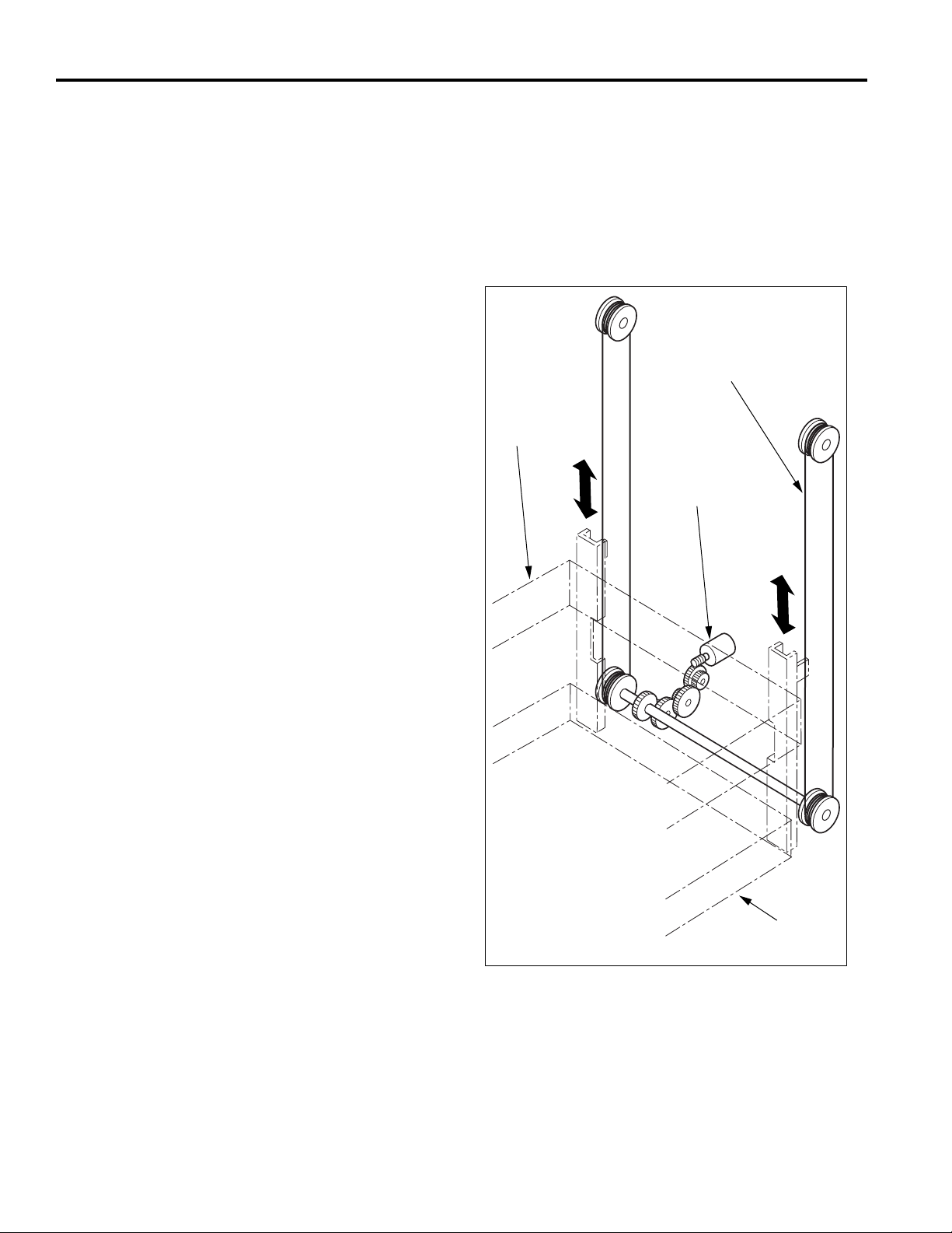
Removing and Reinstalling the Lift Wire
a. Procedure
(1) Remove the tray 2 and tray 3.
(2) Remove the external covers.
Note: The lift wire must be removed (and
installed) first on the front side and then on
the rear side.
(3) Remove the two set screws, then release the wire
fastening bracket (front).
(4) Loosen the two set screws, then release the pulley
tensioning plate (front).
(5) Remove the E ring of the lower pulley (front).
(6) Remove the lower pulley (front), then remove the lift
wire (front).
(7) Attach the metal ball of the lift wire to the inside of the
lower pulley (front) and pass the pulley onto the shaft.
The end of the wire attached to the pulley must be the
short end as seen from the wire fastening bracket.
Note: When installing the lower pulley (front)
onto the shaft, align the pin on the shaft
with the lower pulley (front).
(8) Wind the lift wire five turns around the lower pulley
(front) and then hook the wire onto the upper pulley
(front).
Note: Wind the wire clockwise as seen from the
front.
(9) Route the lift wire from the upper pulley (front) back
down to the lower pulley (front) and wind it one turn in
clockwise direction around the pulley. Then attach the
metal ball at the end of the wire to the side of the lower
pulley (front).
(10) Attach the E ring to secure the lower pulley (front).
Pulley tensioning plate (rear)
Metal ball
(winding start)
Metal ball (winding end)
Set screws
Wire fastening bracket
Metal ball (winding end)
Set screws
Wire fastening bracket (rear)
Lower pulley (rear)
1 turn
5 turn
Upper pulley (rear)
Lift wire
Pin
Shaft
Pulley tensioning plate (front)
Upper pulley (front)
Set screws
Lift wire
Wire fastening bracket (front)
Set screws
E ring
Lower pulley (front)
Metal ball
(winding end)
5 turn 1 turn
Metal ball (winding start)
23
Metal ball (winding start)
Page 32

FS-109
(11) Pull the pulley tensioning plate (front) up until a tension
of 2.3 kg is achieved, then fasten the plate with the two
set screws.
Note: Use a tension gauge or similar when
fastening the pulley tensioning plate, to
assure that the specified tension value is
achieved.
Specification: 2.3 kg
Tension gauge
Set
screws
Pulley
tensioning
plate (front)
Lift wire
(19) Install the tray 2 and move its position in the vertical
direction so that the tray is flush with the lower limit
detection plate. Then permanently secure the wire
fastening brackets (front) and (rear) which were
provisionally fastened previously.
Note: To check the flush condition, use a metal
ruler or other suitable tool on both the front
and the rear side.
Lower limit detection plate
Tray 2
Metal scales
(12) Provisionally fasten the two set screws of the wire
fastening bracket (front).
(13) Remove the lift wire on the rear side in the same way as
described in steps (3) through (6).
(14) Attach the metal ball of the lift wire to the inside of the
lower pulley (rear) and pass the pulley onto the shaft.
The end of the wire attached to the pulley must be the
short end as seen from the wire fastening bracket.
Note: When setting the lower pulley (rear) onto
the shaft, align the pin on the shaft with the
lower pulley (rear).
(15) Wind the lift wire five turns around the lower pulley
(rear) and then hook the wire onto the upper pulley
(rear).
Note: Wind the wire counterclockwise as seen
from the front.
(16) Route the lift wire from the upper pulley (rear) back
down to the lower pulley (rear) and wind it one turn in
counterclockwise direction around the pulley. Then at
tach the metal ball at the end of the wire to the side of
the lower pulley (rear).
(17) Attach the E ring to secure the lower pulley (rear).
(18) Fasten the pulley tensioning plate (rear) and wire
fastening bracket (rear) as described in steps (11) and
(12).
24
Page 33

FS-109
Replacing the Stapler Cartridge
a. Procedure
(1) Push the release lever to remove the finisher from the
main body.
(2) Push the release levers of the stapler units down and
remove the stapler cartridges.
Release lever
Release lever
Stapler cartridge
Stapler
cartridge
Removing and Reinstalling the Stapler
Unit
a. Procedure
(1) Remove the set screw (one each), then remove the
alignment plate (front) and alignment plate (rear).
Alignment
plate
(front)
Alignment
plate
(rear)
Set screws
Lower limit
detection plate
Film
(3) Push the new stapler cartridge all the way in, until it is
locked in the stapler unit.
(2) Remove the four set screws, then remove the stapler
unit cover (lower).
(3) Disconnect the three connectors (CN705, 706 and
707) on the FNSCB FNS control board and also the
connector (CN726) on the tray up-down motor.
(4) Remove the four set screws, then pull the stapler unit
out.
Caution: Take care not to bend the film on the
exit side during re-installation.
Top cover
Stapler unit
Set screws
Set
screws
Stapler unit
cover (lower)
Set screws
Set screws
25
Page 34

FS-109
(5) Turn the stapler unit gear, then open the stapler unit
(front) and stapler unit (rear) towards the outside.
(6) Remove the two set screws each, then remove the
connector cover of each stapler unit.
Set screws
Stapler unit (rear)
Stapler unit (front)
Set
screws
Connector
cover
Stapler unit movement gear
Connector
cover
Set
screws
(7) Remove the two set screws each, then remove the
stapler unit (front) and stapler unit (rear).
(8) Disconnect the connector (CN745, CN746) from each
stapler unit.
(9) Remove the two set screws, then remove the stapler
unit.
Set screws
Stapler chassis
Stapler unit
(10) Reinstall the stapler unit in the opposite sequence to
removal.
Set screws
Connector
(CN745)
Set screws
Stapler unit (front) Stapler unit (rear)
Connector
(CN746)
26
Page 35

FS-109 ELECTRICAL PARTS LAYOUT DRAWING
PS819
PS803
MS802
Up-down MS (upper)
PS801
Drum position detect PS
Tray 1 paper exit detect PS
FNSCB
FNS control board
PS802
Drum entrance PS
PS809
Tray 3 full-stack detect PS
PS817
Stapler HP (front) PS
PS820
Stapler HP (rear) PS
PS804
Paper through detect PS
PS807
Tray 2 full-stack detect PS
M810
Tray 2 motor
M811
Tray 3 motor
M806
Stapler movement motor
No-staple (front) (lead edge) PS
PS822
No-staple (rear) (lead edge) PS
PS818
No-staple (front) PS
PS821
No-staple (rear) PS
M805
Paper exit motor
DIAGRAMS
PS805
Tray upper limit
PS
M801
Conveyance
motor
MS803
Up-down MS (lower)
PS806
Tray lower limit PS
SD801
Gate SD
MS801
Inter lock MS
M809 Alignment motor (front)
M807
Conveyance drum
motor
SD802
Shutter SD
MS804
Stapler safety MS
M804
Tray up/down motor
PS812
Stapler no paper
PS815
Alignment motor
(front) HP PS
PS
PS813
Paper exit motor
HP PS
M803
Stapler motor (front)
M808
Alignment motor (rear)
PS816
Alignment motor (rear) HP PS
M802
Stapler motor (rear)
PS814
Stapler unit HP PS
27
Page 36

DIAGRAMS
FS-109 CONNECTOR LAYOUT DRAWING
730 (W:2 PIN)
756 (BK:8 PIN)
736 (W:3 PIN)
759 (W:3 PIN)
749 (W:9 PIN)
757(BK:8 PIN)
761 (BK:8 PIN)
737 (W:3 PIN)
401 (GY:16 PIN)
750
(W:12 PIN)
753
(W:6 PIN)
734 (W:3 PIN)
754 (W:2 PIN)
721 (W:6 PIN)
733 (W:3 PIN)
726
(BK:2 PIN)
724 (W:6 PIN)
763
(W:3 PIN)
724 (W:6 PIN)
744 (W:3 PIN)
760 (W:3 PIN)
751 (W:3 PIN)
723 (W:6 PIN)
727 (W:6 PIN)
725 (W:6 PIN)
743 (W:3 PIN)
741 (W:3 PIN)
740 (W:3 PIN)
746 (W:13 PIN)
742 (W:3 PIN)
745 (W:13 PIN)
722
(W:6 PIN)
729(W:6 PIN)
751 (BK:3 PIN)
728 (W:6 PIN)
752 (W:3 PIN)
(W:10 PIN)
752 (W:3 PIN)
28
702 (W:6 PIN)
701
711
(W:2 PIN)
709
(W:2 PIN)
FNSCB
704 (W:28 PIN)
703 (W:24 PIN)706 (W:15 PIN)
713
(GY:30 PIN)
712
(W:15 PIN)
710
(W:3 PIN)
707
(W:24 PIN)
705 (W:24 PIN)
Page 37

TIMING CHART
FS-109 TIMING CHART
8.5x11, SORT MODE, 3 SHEETS, 3 SETS
(sec)
110ms
260ms
320ms
110ms
260ms
320ms
110ms
260ms
70ms 70ms
240ms
200ms
10ms
10ms
10ms
60ms
190ms
60ms
250ms
60ms
8.5x11, 3 SHEETS, 2 PLACES STAPLING,
2 SETS
330ms
280ms
320ms
110ms
260ms
320ms
110ms
260ms
280ms
10ms
10ms
60ms
10ms
330ms
60ms
400ms
100ms
10ms
330ms
280ms
280ms
10ms
60ms
330ms
320ms
110ms
260ms
320ms
110ms
260ms
70ms 70ms
200ms
200ms
210ms
250ms
250ms
320ms
110ms
260ms
70ms 70ms 70ms
250ms
320ms
110ms
260ms
0 1 2 3 4 5 6
29
Page 38

TIMING CHART
FS-109 TIMING CHART
11x17, 3 SHEETS, 3 PLACES STAPLING, 3 SETS
(sec)
280ms
280ms
140ms
140ms
600ms
600ms
10ms
10ms
10ms
10ms
60ms
10ms
650ms
60ms
650ms
60ms
10ms
140ms
650ms
600ms
1 2 3 4 5 6 7 8 9
270ms 280ms
0
30
Page 39

PAPER THROUGH
DETECTSENSOR
DRUM POSITION
DETECT SENSOR
DRUM ENTRANCE
SENSOR
TRAY 1
PAPER EXIT
DETECT SENSOR
TRAY
UPPER LIMIT
SENSOR
TRAY
LOWER LIMIT
SENSOR
TRAY 3
FULL–STACK
DETECT SENSOR
TRAY 2
FULL–STACK
DETECT SENSOR
STAPLER NO
PAPER SENSOR
PAPER EXIT
MOTOR HP SENSOR
STAPLER UNIT HP SENSOR
ALIGNMENT MOTOR
HP (FRONT) SENSOR
ALIGNMENT MOTOR
(REAR) HP
STAPLER (FRONT)
MOTOR
STAPLER HP (FRONT) SENSOR
NO STAPLE (FRONT) SENSOR
FS-109 OVERALL WIRING DIAGRAM
NO STAPLE (FRONT)
(LEAD EDGE) SENSOR
STAPLER (REAR)
MOTOR
STAPLER HP (REAR) SENSOR
NO STAPLE (REAR) SENSOR
NO STAPLE (REAR)
(LEAD EDGE) SENSOR
TRAY UP/DOWN
MOTOR
M804
CN726–1
CN726–2
UL1007#24
UL1007#24
23
24
CN707–A8 M804 DRV1
CN707–A9 M804 DRV2
H
H
1516192021
25314
CN727–2
CN727–5
25314
UL1007#24
5253545556
CN705–B7 24V
CN704–B1 24V
CN704–B2 24V
CN704–B5 M801 DRVA
CN704–B6 M801 DRVA
P
PPP
UL1007#24
UL1007#24
UL1007#24
UL1007#24
PAPER EXIT
MOTOR
M805
CN727–3
CN727–6
CN727–4
UL1007#24
UL1007#24
UL1007#24
UL1007#24
CN705–B10 M805 DRVA
CN705–B11 M805 DRVB
CN705–B9 M805 DRVA
CN705–B8 24V
PPP
CN704–B7 M801 DRVB
CN704–B8 M801 DRVB
22
UL1007#24
UL1007#24
6
CN727–1
6
UL1007#24
57
CN705–B12 M805 DRVB
P
TRAY 2 MOTOR
M810
CN728–5
CN728–6
CN728–1
CN728–3
18
CN753–12
CN753–11
CN753–10
CN753–9
CN753–1
CN753–2
CN753–3
CN753–4
UL1007#26
UL1007#26
UL1007#26
34789
CN704–A7 M810 DRVA
CN704–A4 24V
CN704–A3 24V
PPP
CN704–B3 24V
CN704–B4 24V
PPP
1718232425
UL1007#24
UL1007#24
25314
CN728–2
CN728–4
1314151617
CN753–8
CN753–7
CN753–5
CN753–6
UL1007#26
UL1007#26
UL1007#26
10
CN704–A9 M810 DRVB
CN704–A10 M810 DRVB
CN704–A8 M810 DRVA
P
CN704–B9 M807 DRVA
CN704–B10 M807 DRVA
CN704–B11 M807 DRVB
P
UL1007#24
UL1007#24
UL1007#24
CN704–B12 M807 DRVB
26
UL1007#24
6
TRAY 3 MOTOR
M811
CN729–5
CN729–6
CN729–1
CN729–3
12
CN753–6
CN753–5
CN753–4
CN753–3
CN753–7
CN753–8
CN753–9
CN753–10
UL1007#26
UL1007#26
UL1007#26
UL1007#26
56111213
CN704–A12 M811 DRVA
CN704–A11 M811 DRVA
CN704–A6 24V
CN704–A5 24V
PPP
4647484950
CN762–1
CN763–6
6
CN729–2
CN729–4
7891011
CN753–2
CN753–1
CN753–11
CN753–12
UL1007#26
UL1007#26
14
CN704–A14 M811 DRVB
CN704–A13 M811 DRVB
P
CN705–B1 24V
CN705–B2 24V
CN705–B3 M808 DRVA
CN705–B4 M808 DRVA
PPP
UL1007#26
UL1007#26
UL1007#26
UL1007#26
CN762–4
CN762–5
CN762–3
CN762–2
CN763–5
CN763–4
CN763–3
CN763–2
GATE SOLENOID
SD801
CN730–1
CN730–2
UL1007#26
UL1007#26
2
1
CN704–A1 24V
CN704–A2 SD801 DRV
H
CN705–B5 M808 DRVB
CN705–B6 M808 DRVB
P
51
UL1007#26
UL1007#26
CN762–6
CN763–1
12345
SHUTTER SOLENOID
SD802
CN731–2
CN731–1
1
2
CN748–1
CN748–2CN748–1
CN748–2
UL1007#26
UL1007#26
27
28
CN704–B14 24V
CN704–B13 SD802 DRV
H
CN705–A1 24V
CN705–A3 M809 DRVA
CN705–A2 24V
CN705–A4 M809 DRVA
PPP
3436373839
35
UL1007#26
UL1007#26
UL1007#26
UL1007#26
CN761–1
CN761–2
CN761–3
CN761–4
CN761–5
CN761–6
CN761–5
CN761–4
CN761–3
CN761–2
456
PS804
CN760–1
CN760–2
CN760–3
543
CN763–3
CN760–2
CN763–1CN763–3
CN763–2
CN763–1
UL1007#26
UL1007#26
UL1007#26
424140
CN703–A11 PS804IN
CN703–A12 VCC
CN703–A10 GND
CN705–A7 24V
CN705–A6 M809 DRVB
CN705–A5 M809 DRVB
P
4042434445
UL1007#26
UL1007#26
UL1007#26
CN725–6
CN761–6
CN725–1
CN761–1
132
CN705–A8 24V
CN705–A9 M806 DRVA
CN705–A10 M806 DRVA
PPP
41
UL1007#26
UL1007#26
UL1007#26
CN725–1
CN725–2
CN725–3
CN725–5
CN725–6
CN725–5
CN725–4
CN725–2
PS801
CN732–3
CN732–2
CN732–1
UL1007#26
UL1007#26
UL1007#26
484746
CN703–B5 PS801IN
CN703–B4 GND
CN703–B6 VCC
CN705–A12 M806 DRVB
CN705–A11 M806 DRVB
P
UL1007#26
UL1007#26
CN725–4
CN725–3
PS802
CN733–1
CN733–2
CN733–3
UL1007#26
UL1007#26
UL1007#26
454344
CN703–B1 GND
CN703–B2 PS802IN
CN703–B3 VCC
L
T
OU
V
24
CN711–2
2
UL1015#18
IN
V
24
CN711–1
1
UL1015#18
PS803
CN734–1
CN734–2
CN734–3
CN736–1
UL1007#26
UL1007#26
UL1007#26
UL1007#26
39
37
3635343332
38
CN703–A6 VCC
CN703–A8 PS803IN
CN703–A7 GND
CN703–A9 VCC
L
FNSCB
T
OU
V
24
CN710–2
30
UL1007#22
CN754–1
CN754–2
UL1015#18
UL1015#18
PS805
PS806
CN736–2
CN736–3
CN737–1
CN737–2
UL1007#26
UL1007#26
UL1007#26
UL1007#26
UL1007#26
CN703–A3 VCC
CN703–A2 PS806IN
CN703–A4 GND
CN703–A5 PS805IN
L
H
55
29
UL1007#22
CN755–2
CN755–1
UL1015#18
CN737–3
CN752–1
CN752–2
CN750–5
CN750–6
CN750–1
CN750–2
UL1007#26
UL1007#26
UL1007#26
UL1007#26
31
545352
CN703–A1 GND
CN703–B12 VCC
V IN
24
CN710–1
UL1007#22
UL1015#18
PS809
CN751–1
CN752–3
456
CN750–3
CN750–4
CN750–3
CN750–4
UL1007#26
UL1007#26
UL1007#26
UL1007#26
UL1007#26
51
CN703–B10 GND
CN703–B11 PS809IN
CN703–B9 VCC
L
V IN
V OUT
24
24
CN709–1
CN709–2
1
2
UL1007#18
UL1015#18
PS807
CN751–2
CN751–3
123
CN750–1
CN750–2
CN750–5
CN750–6
UL1007#26
UL1007#26
UL1007#26
50
49
CN703–B8 PS817IN
CN703–B7 GND
L
PS812
CN740–1
CN740–2
CN740–3
789
CN749–8
CN749–7
CN759–1 CN749–9
CN749–3
CN749–2
UL1007#26
UL1007#26
UL1007#26
UL1007#26
UL1007#26
151413
CN706–13 GND
CN706–14 PS812IN
CN706–15 VCC
PS813
CN741–1
CN741–2
CN741–3
456
CN749–6
CN749–5
CN749–4
CN749–6
CN749–5
CN749–4
UL1007#26
UL1007#26
UL1007#26
UL1007#26
UL1007#26
12
10
11
CN706–12 VCC
CN706–10 GND
CN706–11 PS813IN
H
PS814
CN742–1
CN742–2
CN742–3
123
CN749–3
CN749–2
CN759–1
CN749–9
CN749–8
CN749–7
UL1007#26
UL1007#26
UL1007#26
UL1007#26
UL1007#26
789
CN706–7 GND
CN706–8 PS814IN
CN706–9 VCC
L
PS815
PS816
CN743–1
CN743–2
CN743–3
CN744–1
CN744–2
CN744–3
789
789
CN759–3
CN759–2
CN758–3
CN758–2
CN758–2
CN758–1
UL1007#26
UL1007#26
CN706–6 VCC
H
GND
S.
CN701–1
123456789
UL1007#24
CN401–5 S.GND
CN759–1
CN758–1
CN759–3
CN759–2
CN759–1
CN758–3
UL1007#26
UL1007#26
UL1007#26
UL1007#26
UL1007#26
UL1007#26
123
456
CN706–2 PS816IN
CN706–5 PS815IN
CN706–3 VCC
CN706–4 GND
H
GND
GND
GND
V
V
S.
5
5
P.
P.
CN701–4
CN701–5
CN701–2
CN701–3
CN701–6
UL1007#24
UL1007#24
UL1007#24
UL1007#24
UL1007#24
CN401–7 P.GND
CN402–5 P.GND
CN402–1 S.GND
CN401–8 5V
CN402–2 5V
UL1007#26
UL1007#26
CN706–1 GND
.GND
P
CN701–7
UL1007#24
CN402–3 P.GND
M803
CN745–3
CN745–1
CN745–6
1234567
CN756–1
CN756–2
CN756–3
16171920212218
UL1007#26
UL1007#24
UL1007#24
CN707–A1 M803 DRV1
CN707–A4 VCC
CN707–A2 M803 DRV2
V
V
V
_TXD
_REQ
24
24
24
M
M
CN702–2
CN701–8
CN701–9
CN701–10
CN702–1
PPPPP
10111213141516
UL1007#24
UL1007#24
UL1007#24
UL1007#26
UL1007#26
CN401–4 M_TxD
CN401–3 M_REQ
CN401–8 24V
CN402–8 24V
CN402–4 24V
PS817
PS818
PS819
CN745–5
CN745–11
CN745–7
CN745–9
8
CN756–4
CN756–5
CN756–6
CN756–7
CN756–8
59
UL1007#26
UL1007#26
UL1007#26
UL1007#26
UL1007#22
CN707–A3 GND
CN707–A7 PS819IN
CN707–A6 PS818IN
CN707–A5 PS817IN
LLL
_RXD
_ACK
_ACK
_REQ
S
M
M
S
CN702–3
CN702–5
CN702–6
CN702–4
P
UL1007#26
UL1007#26
UL1007#26
UL1007#26
CN402–7 S_ACK
CN401–1 S_RxD
CN402–8 S_REQ
CN401–2 M_ACK
CN746–1
1234567
CN757–1
33323029282831
17
UL1015#18
EARTH
CN100–
MAIN BODY
M802
+5V
CN746–3
CN746–6
CN757–2
CN757–3
UL1007#24
UL1007#24
UL1007#24
CN707–B9 M802 DRV1
CN707–B8 M802 DRV2
CN707–B6 VCC
PS820
PS821
PS822
GND
CN746–9
CN746–7
CN746–11
CN746–5
8
CN757–4
CN757–5
CN757–6
CN757–7
CN757–8
58
UL1007#24UL1007#24
UL1007#24
UL1007#24
UL1007#24
UL1007#22
CN707–B7 GND
CN707–B3 PS822IN
CN707–B4 PS821IN
CN706–B5 PS820IN
LLL
[How to see the diagram]
1.The signals shown reflect levels present
under normal idling conditions with
the main switch turned ON.
2.Wiring symbols in the figure are as follows.
(1) [Symbol]
(2)
Crimp
Signal typs are as follows :
Active high
H
Active low
L
Analog signal
*
Pulse signal
P
V
50-1
Connector
V
Faston
Wire(Violet)
(3) RC is ribbon cable.
(4) Signal flow
The solid black circle ( ) among
the connector symbols ( )
indicates the direction of signal flow.
Example)
5VDC
PS1
Direction of
signal flow
PS1
CB
SGND
CN721–2
CN721–5
CN721–6
CN721–4
M801
ONVEYANCE MOTOR
CN721–3
CN721–1
CN722–2
CN722–5
CN722–6
CN722–4
M807
CONVEYANCE
DRUM MOTOR
CN722–3
CN722–1
CN723–5
CN723–6
CN723–1
CN723–2
CN723–1
CN723–3
CN723–2
CN723–5
CN723–4
CN723–6
M808
ALIGNMENT
MOTOR (REAR)
CN723–4
CN723–3
31
CN724–6
CN724–5
CN724–2
CN724–1
CN724–3
CN724–1
CN724–6
CN724–4
M809
ALIGNMENT
MOTOR (FRONT)
CN724–4
CN724–2
CN724–5
CN724–3
M806
STAPLER
MOVEMENT
MOTOR
MS801
INTER LOCK MS
MS802
UP–DOWN
MS (UPPER)
MS803
UP–DOWN
MS (LOWER)
MS804
STAPLER
SAFETY
MS
Page 40

This page left blank intentionally.
32
Page 41

PARTS CATALOG
Model
FS-109
NOVEMBER 2000
KONICA BUSINESS TECHNOLOGIES, INC.
Page 42

Page 43

How to use this catalog
This parts catalog includes illustrations and part numbers for all replacement parts and assemblies used in this model.
Model-specific parts are identified in the illustrations with reference
numbers. Use the reference number to locate the corresponding part
number on the facing page.
Common hardware items, such as screws, nuts, washers, and pins,
are identified in the illustrations with reference letters. Use the reference
letter to locate the corresponding part number on the hardware listing in
the lower right hand corner of the facing page.
If you know a part number, but don’t know where the part is used, use
the numerical index to determine the page number and reference number for that part. Because some common parts are used in several
places, there may be more than one entry. Refer to the illustrations to
see where the part may be used.
If you know a part’s description, but don’t know where to look to find
the part number, use the alphabetical index to determine likely page and
reference numbers. Then look at the illustrations to determine that you
have identified the correct part. Locate the part number using the listing
on the opposite page.
Retail pricing that appears with the numerical index, while valid when
this catalog was printed, is subject to change without notice. The prices
are only suggested prices and are provided only for reference. Dealers
may determine their own selling prices. For up-to-date pricing, refer to
current Konica price lists or contact the Konica Parts Distribution Center.
How to order parts
Use standard Konica parts ordering procedures to obtain these parts.
For ordering options, contact Konica’s Parts Distribution Center.
When ordering parts, be sure to specify part numbers exactly as listed in
this catalog.
NOTE: Electrical parts may include previously used components.
Model FS-109 Konica Business Technologies, Inc. Page iii
1st Edition November, 2000
Page 44

This page left blank intentionally.
Page iv Konica Business Technologies, Inc. Model FS-109
November, 2000 1st Edition
Page 45

How to use this catalog . . . . . . . . . . . . . . . . . . . . . . . . . iii
Contents . . . . . . . . . . . . . . . . . . . . . . . . . . . . . 1
FS-109 . . . . . . . . . . . . . . . . . . . . . . . . . . . . . 2
Wiring . . . . . . . . . . . . . . . . . . . . . . . . . . . . 24
Alphabetical index . . . . . . . . . . . . . . . . . . . . . . . . . . . 29
Numerical index, Retail price list . . . . . . . . . . . . . . . . . . . . 31
Contents
Model FS-109 Konica Business Technologies, Inc. Page 1
1st Edition November, 2000
Page 46

FS-109
Page 2 Konica Business Technologies., Inc. Model FS-109
November, 2000 1st Edition
Page 47

REF. PART NUMBER DESCRIPTION
NO.
1 13LP10050 Support panel/left
2 120H10240 Protect sheet/B
3 13LP48030 Paper exit driving rail/front
4 120H73011 Electrical parts MT plate
5 13LP-9010 FNS control unit
6 13LP90010 FNS wiring/1
7 13LP48040 Paper exit driving rail/rear
8 120H73050 Presser sheet
9 12AR45611 Actuator
10 12QR86010 Interlock switch
11 120H73020 Sensor MT plate
12 120H12080 External MT plate/D
13 120H10030 Bottom plate
14 13LP20050 Carriage cover
15 120H10060 Side cover/right
16 120H10070 Main body fixed plate
17 120H50240 Rear plate
18 25BA10160 Carriage support material/B
19 13LP20130 Carriage support material/A
20 12AR74020 Screw/B
21 13LP20030 Carriage fixed plate
22 120H20040 Carriage rail
23 120H20090 Main body regulating stopper
24 13LP20010 Carriage support plate/front
25 120H20080 Main body stopper
26 120H20020 Carriage support plate/rear
27 120H20060 Carriage fulcrum shaft
28 120H-2050 Connecting plate/front ass’y
29 120H-2060 Connecting plate/rear ass’y
30 120H20070 Carriage stay
31 120H-1160 Main body PS plate ass’y
32 120H12070 External MT plate/C
HARDWARE
REF.
LTR.
a 00Z193181
b 00Z925103
c 00Z194061
d 00Z144062
e 00Z193061
f 00Z184061
g 00Z921303
h 00Z194201
j 00Z921302
k 00Z163081
m 00Z164081
n 00Z192101
p 00Z194201
PART
NUMBER
Model FS-109 Konica Business Technologies., Inc. Page 3
1st Edition November, 2000
Page 48

FS-109
Page 4 Konica Business Technologies., Inc. Model FS-109
November, 2000 1st Edition
Page 49

REF. PART NUMBER DESCRIPTION
NO.
1 13LP48010 Paper exit tray/A
2 13LP48020 Paper exit tray/B
3 13LP80020 FNS motor/1
4 13LP77550 Driving belt/E
5 13LP-4980 Driving roller/A assy
6 13GQ76020 Bearing/A
7 120H48060 Support spring
8 13LP48410 Sensor MT plate
9 12QV85510 Sensor
10 13LP97030 Indication label/A
11 120H12010 Front cover
12 120H12030 Upper plate
13 120H12040 Rear AUX cover
14 120H12020 Rear cover
15 13LP48370 Paper exit driving cover
16 13LP48500 Wiring holding part
HARDWARE
REF.
LTR.
a 00Z253081
b 00Z144082
c 00Z253082
d 00Z183041
e 00Z194061
f 00Z144062
g 00Z670606
PART
NUMBER
Model FS-109 Konica Business Technologies., Inc. Page 5
1st Edition November, 2000
Page 50

FS-109
Page 6 Konica Business Technologies., Inc. Model FS-109
November, 2000 1st Edition
Page 51

REF. PART NUMBER DESCRIPTION
NO.
1 120H10160 Detecting plate/upper
2 120H10230 Switch input material
3 12QV85510 Sensor
4 13LP-4300 Sensor MT plate unit assy
5 120H42240 Stopper part
6 120H42230 Sensor spring/B
7 120H42201 Paper detecting actuator
8 12AR45131 Entrance pressure spring
9 120H42161 RF stay
10 120H48090 Sensor MT plate/A
11 120H73030 Wiring MT base
12 12QR86010 Interlock switch
13 120H12110 Release lever
14 120H10130 Lever MT plate
15 120H10140 Hinge guide plate
16 12AR45650 Stopper part
17 13LP10150 Lever fulcrum shaft
18 120H-1140 Lever release plate/A ass’y
19 13LP10190 Fulcrum shaft/A
20 120H10170 Open-close spring
21 13LP90110 Paper exit wiring/1
22 120H10120 Connecting plate
23 12AR-4590 Rocking part ass’y
24 120H10090 Main body lock plate
25 120H10080 Main body lock shaft
26 120H10210 Paper exit panel/D
27 13LP10200 Support shaft/B
28 120H10180 Paper exit protection cam
29 13LP90100 Paper exit wiring
30 13LP45480 Switch lever
HARDWARE
REF.
LTR.
PART
NUMBER
a 00Z193061
b 00Z182081
d 00Z163061
e 00Z670306
f 00Z670606
h 00Z670206
i 00Z194061
j 00Z254081
k 00Z193081
m 00Z924692
n 00Z921930
p 00Z921931
q 00Z921110
r 00Z193141
t 00Z921108
u 00Z670506
v 00Z263061
Model FS-109 Konica Business Technologies., Inc. Page 7
1st Edition November, 2000
Page 52

FS-109
Page 8 Konica Business Technologies., Inc. Model FS-109
November, 2000 1st Edition
Page 53

REF. PART NUMBER DESCRIPTION
NO.
1 13LP80010 FNS driving unit
2 120H18060 Up-down wire/R
3 12QR48070 Up-down pulley
4 002075580 Bushing
5 13LP77060 Up-down gear/C (Z=30)
6 304078070 Pin C
7 120H18020 Up-down shaft/A
8 12QR-4820 Tension plate ass’y
9 12QR48270 Tension pulley
10 120H48110 Paper exit up-down spring
11 120H48300 Paper exit lift-up rail/rear
12 120H18050 Up-down wire/F
13 120H48290 Paper exit lift-up rail/front
14 120H48080 Driving guide roller
15 120H48070 Driving guide shaft
HARDWARE
REF.
LTR.
a 00Z670806
b 00Z670606
c 00Z194061
d 00Z164081
e 00Z924690
f 00Z924692
g 00Z924316
PART
NUMBER
Model FS-109 Konica Business Technologies., Inc. Page 9
1st Edition November, 2000
Page 54

FS-109
Page 10 Konica Business Technologies., Inc. Model FS-109
November, 2000 1st Edition
Page 55

REF. PART NUMBER DESCRIPTION
NO.
1 12QV85510 Sensor
2 120H42141 Sensor MT plate
3 13LP42150 Sensor shaft
4 120H42191 Sensor spring
5 120H42201 Paper detecting actuator
6 13LP42100 Conveyance driving roller/A
7 13LP42080 Conveyance open-close spring/front
8 120H42011 Conveyance guide plate/A
9 120H42030 Conveyance guide plate/C
10 120H77050 Conveyance gear (Z=60)
11 322076010 Paper lift-up lever shaft holder
12 13LP-4270 Pressure shaft/A
13 13LP80040 FNS motor/3
14 120H42180 Collar
15 120H77530 Driving belt/C (L=390)
16 120H42070 Conveyance fulcrum shaft
17 120H76520 Conveyance driving pulley (Z=24)
18 120H42210 Pressure part/C
19 120H42240 Stopper part
20 048645260 Stopper rubber
21 120H42020 Conveyance guide plate/B
22 120H42060 Conveyance lift-up plate
23 12AR45180 Entrance roller
24 12QR45180 Conveyance pressure spring
HARDWARE
REF.
LTR.
a 00Z163061
b 00Z670406
c 00Z193061
d 00Z670206
e 00Z193041
f 00Z670606
g 00Z921930
PART
NUMBER
Model FS-109 Konica Business Technologies., Inc. Page 11
1st Edition November, 2000
Page 56

FS-109
Page 12 Konica Business Technologies., Inc. Model FS-109
November, 2000 1st Edition
Page 57

REF. PART NUMBER DESCRIPTION
NO.
1 12QR47210 Neutralizing brush
2 12AR45180 Entrance roller
3 13LP-4280 Pressure shaft/B
4 120H42040 Conveyance guide plate/D
5 120H48330 Spring MT plate
6 120H10270 Positioning plate
7 13LP42110 Paper exit driving roller
8 120H77050 Conveyance gear (Z=60)
9 322076010 Paper lift-up lever shaft holder
10 120H-4030 Spring MT plate unit
11 120H40040 Solenoid MT plate
12 12AR45670 Solenoid oscillate spring
13 120H-4020 Solenoid MT ass’y
14 120H10280 Holding spring
15 466078010 Pin A
16 120H42050 Conveyance guide plate/E
17 120H40020 Conveyance regulating shaft
18 120H40010 Conveyance AUX plate
19 120H48430 Spring MT plate/rear
20 12AR45650 Stopper part
21 059045110 Sheet/C
22 120H42210 Stopper part/C
HARDWARE
REF.
LTR.
a 00Z670406
c 00Z163061
d 00Z194061
e 00Z670206
f 00Z193061
g 00Z670306
PART
NUMBER
Model FS-109 Konica Business Technologies., Inc. Page 13
1st Edition November, 2000
Page 58

FS-109
Page 14 Konica Business Technologies., Inc. Model FS-109
November, 2000 1st Edition
Page 59

REF. PART NUMBER DESCRIPTION
NO.
1 120H45080 Paper hold plate
2 13LP45230 Shaft/B
3 120H45050 Paper hold spring
4 120H45040 Rotary shaft
5 120H45130 Drum AUX plate/2
6 120H45120 Drum AUX plate/1
7 120H45060 Paper hold shaft
8 120H45010 Paper conveyance drum
9 120H45070 Oscillate shaft
10 120H45160 Stopper material
11 120H45190 Stopper collar
12 090075530 Bearing
13 120H77020 Drum drive gear (Z=80)
14 120H45180 Paper hold rubber
15 120H45370 Paper exit AUX plate
16 13LP-4620 Drum driving shaft assy
17 120H10040 Drum upper plate
18 120H45020 Drum cover/front
19 120H45390 Neutralizing filter/front
20 120H45380 Filter holding part
21 120H45030 Drum cover/rear
22 120H45400 Neutralizing filter/rear
23 13LP97070 Indication label/B
24 12ER40350 Pad
HARDWARE
REF.
LTR.
a 00Z670601
b 00Z193061
c 00Z670256
d 00Z173061
e 00Z474043
f 00Z194061
g 00Z670206
h 00Z283061
i 00Z163181
j 00Z253081
PART
NUMBER
Model FS-109 Konica Business Technologies., Inc. Page 15
1st Edition November, 2000
Page 60

FS-109
Page 16 Konica Business Technologies., Inc. Model FS-109
November, 2000 1st Edition
Page 61

REF. PART NUMBER DESCRIPTION
NO.
1 120H45140 Cam
2 120H-4540 Sensor MT plate ass’y
3 120H45270 Sensor spring/B
4 120H45220 Paper detecting actuator
5 120H45110 Stay
6 120H45250 Sensor MT plate
7 120H45090 Regulating plate
8 120H45240 Driving shaft
9 120H45340 Staple PV spring
10 120H45320 Solenoid MT plate
11 13LP-4550 Pressure spring ass’y
12 120H45300 Fulcrum plate/front
13 120H45280 Staple PV plate
14 120H45290 Staple PV lever
15 13LP80040 FNS motor /3
16 192141710 Paper lift-up lever shaft holder
17 120H-4570 Solenoid ass’y
18 120H45310 Fulcrum plate/rear
19 12WM77600 Driving belt
20 120H77010 Idler gear (Z=20/48)
21 13LP45460 Spring mounting plate
22 120H45420 Stopper part/B
23 12QV85510 Photosensor
HARDWARE
REF.
LTR.
a 00Z670406
b 00Z193061
c 00Z670256
d 00Z163061
e 00Z254081
f 00Z193041
PART
NUMBER
Model FS-109 Konica Business Technologies., Inc. Page 17
1st Edition November, 2000
Page 62

FS-109
Page 18 Konica Business Technologies., Inc. Model FS-109
November, 2000 1st Edition
Page 63

REF. PART NUMBER DESCRIPTION
NO.
1 120H55080 Spacer/A
2 120H55010 Paper exit lever/A
3 120H55130 Paper exit lever/B
4 120H60110 Paper exit support plate
5 13LP-5070 Staple support plate ass’y
6 462076110 Cleaner rolling shaft holder (B)
7 25AA52140 Belt holder/B
8 12QR77510 Belt/A (L=752)
9 25AA52510 Regulating gear/S (Z=55/28)
10 12QR77010 Staple driving gear (Z=51/21)
11 12QV85510 Sensor
12 120H77070 Staple drive gear/B (Z=112)
13 13GQ80030 FNS motor/1
14 120H77540 Driving belt/D (L=192)
15 120H50200 Lift-up cam
16 120H50230 Sensor MT plate/D
17 120H50350 Protect sheet/F
18 12QR-5050 Tension plate ass’y
19 25AA52710 Idler pulley
20 120H77030 Paper exit gear/A (Z=32)
21 120H55041 Motor MT plate/A
22 13LP80030 FNS motor /2
23 120H50310 Side lock part
24 120H55140 Protect sheet/E
25 120H55091 Paper exit panel/B
26 120H-5551 Sensor MT plate/F ass’y
27 120H55030 Paper exit actuator
28 120H55100 Paper exit arm
29 120H77040 Paper exit gear/B (Z=80)
30 120H98010 Sensor fixed plate
HARDWARE
REF.
LTR.
PART
NUMBER
a 00Z183061
b 00Z670406
c 00Z253081
d 00Z193061
e 00Z163061
f 00Z670606
g 00Z164061
h 00Z924635
i 00Z194061
j 00Z924690
k 00Z163081
m 00Z670407
n 00Z610306
p 00Z670207
Model FS-109 Konica Business Technologies., Inc. Page 19
1st Edition November, 2000
Page 64

FS-109
Page 20 Konica Business Technologies., Inc. Model FS-109
November, 2000 1st Edition
Page 65

REF. PART NUMBER DESCRIPTION
NO.
1 120H60050 Paper exit panel/A
2 25AA52140 Belt holder/B
3 120H77510 Driving belt/A (L=394)
4 25AA52710 Idler pulley
5 13LP90020 FNS wiring/2
6 25AA52510 Regulating gear/S (Z=55/28)
7 120H60190 Protect sheet/C
8 120H60200 Protect sheet/D
9 13LP-6050 Pulley MT plate/A ass’y
10 120H60080 Sensor MT plate/D
11 12QV85510 Sensor
12 13GQ80030 FNS motor/1
13 120H50060 Staple rotary cam
14 120H60120 Paper regulating plate/A
15 120H60150 Connecting plate
16 120H60180 Adjusting plate
17 120H60030 Slide base
18 12QR52090 Fixed block
19 120H60130 Paper regulating plate/B
20 120H60170 RF panel/B
21 120H60160 RF panel/A
22 120H60070 Sensor MT plate/C
23 120H60060 Paper exit panel/C
24 120H50320 Protect sheet
HARDWARE
REF.
LTR.
a 00Z183061
b 00Z163081
c 00Z921302
d 00Z193061
e 00Z163061
f 00Z922440
g 00Z670607
PART
NUMBER
Model FS-109 Konica Business Technologies., Inc. Page 21
1st Edition November, 2000
Page 66

FS-109
Page 22 Konica Business Technologies., Inc. Model FS-109
November, 2000 1st Edition
Page 67

REF. PART NUMBER DESCRIPTION
NO.
1 120H50420 Staple guide block/upper
2 120H50130 Staple MT plate
3 120H50140 Staple cover
4 192141710 Paper lift-up lever shaft holder/B
5 120H50280 Rotary roller
6 13LP-5100 Staple rotary base/A ass’y
7 120H-5150 Mount plate/B ass’y
8 504045110 Stopper roller
9 120H50402 Staple
10 13LP-5110 Staple rotary base/B ass’y
11 120H50220 Regulating plate
12 120H50250 Belt fixed plate
13 12QR52090 Fixed block
14 120H50110 Collar/A
15 120H90032 Relay wiring/1
16 12QR76020 Shaft holder
17 120H50190 Paper PS plate/B
18 120H50180 Paper PS plate/A
19 13LP-5080 Staple slide base/A front ass’y
20 120H50090 Slide shaft holder
21 13LP-5090 Staple slide base/B rear ass’y
22 120H50210 Lock spring
23 120H50170 Staple lock lever
24 13LP90020 FNS wiring/2
25 120H50070 Lever MT plate/A
26 120H50150 Slide shaft/B
27 120H50160 Slide shaft/C
28 120HK0010 Cartridge case
29 12QRK0011 Staples
30 120H50330 Paper positioning plate/C
HARDWARE
REF.
LTR.
PART
NUMBER
a 00Z193061
b 00Z670306
c 00Z670406
d 00Z670606
e 00Z163061
f 00Z193081
g 00Z640305
h 00Z922440
i 00Z922410
Model FS-109 Konica Business Technologies., Inc. Page 23
1st Edition November, 2000
Page 68

Wiring
Page 24 Konica Business Technologies., Inc. Model FS-109
November, 2000 1st Edition
Page 69

REF. PART NUMBER DESCRIPTION
NO.
1 13LP90010 FNS wiring/1
2 13LP90020 FNS wiring/2
3 120H90032 Relay wiring/1
4 13LP90040 Relay wiring/2
Model FS-109 Konica Business Technologies., Inc. Page 25
1st Edition November, 2000
Page 70

Wiring
Page 26 Konica Business Technologies., Inc. Model FS-109
November, 2000 1st Edition
Page 71

REF. PART NUMBER DESCRIPTION
NO.
1 13LP90060 Relay wiring/4
2 13LP90070 Interlock wiring/1
3 13LP90080 Interlock wiring/2
4 13LP90090 Interlock wiring/3
5 13LP90100 Paper exit wiring/1
6 13LP90110 FNS I/F wiring
Model FS-109 Konica Business Technologies., Inc. Page 27
1st Edition November, 2000
Page 72

This page left blank intentionally.
Page 28 Konica Business Technologies, Inc. Model FS-109
November, 2000 1st Edition
Page 73

Alphabetical index
PART PAGE REF.
DESCRIPTION NO. NO.
A
Actuator . . . . . . . . . . 3 9
Adjusting plate . . . . . . . 21 16
B
Bearing . . . . . . . . . . . 15 12
Bearing/A . . . . . . . . . 5 6
Belt fixed plate . . . . . . . 23 12
Belt holder/B . . . . . . . . 19 7
Belt holder/B . . . . . . . . 21 2
Belt/A (L=752) . . . . . . . 19 8
Bottom plate . . . . . . . . 3 13
Bushing . . . . . . . . . . 9 4
C
Cam . . . . . . . . . . . . 17 1
Carriage cover . . . . . . . 3 14
Carriage fixed plate . . . . 3 21
Carriage fulcrum shaft . . . 3 27
Carriage rail . . . . . . . . 3 22
Carriage stay . . . . . . . . 3 30
Carriage support material/A 3 19
Carriage support material/B 3 18
Carriage support plate/front 3 24
Carriage support plate/rear . 3 26
Cartridge case . . . . . . . 23 28
Cleaner rolling shaft holder
(B) . . . . . . . . . . . 19 6
Collar . . . . . . . . . . . . 11 14
Collar/A . . . . . . . . . . 23 14
Connecting plate . . . . . . 7 22
Connecting plate . . . . . . 21 15
Connecting plate/front ass’y 3 28
Connecting plate/rear ass’y 3 29
Conveyance AUX plate . . 13 18
Conveyance driving pulley
(Z=24) . . . . . . . . . 11 17
Conveyance driving roller/A 11 6
Conveyance fulcrum shaft . 11 16
Conveyance gear (Z=60) . . 11 10
Conveyance gear (Z=60) . . 13 8
Conveyance guide plate/A . 11 8
Conveyance guide plate/B . 11 21
Conveyance guide plate/C . 11 9
Conveyance guide plate/D . 13 4
Conveyance guide plate/E . 13 16
Conveyance lift-up plate . . 11 22
Conveyance open-close
spring/front . . . . . . . 11 7
Conveyance pressure spring 11 24
Conveyance regulating shaft 13 17
D
Detecting plate/upper . . . 7 1
Driving belt . . . . . . . . . 17 19
Driving belt/A (L=394) . . . 21 3
Driving belt/C (L=390) . . . 11 15
PART PAGE REF.
DESCRIPTION NO. NO.
Driving belt/D (L=192) . . . 19 14
Driving belt/E . . . . . . . . 5 4
Driving guide roller . . . . . 9 14
Driving guide shaft . . . . . 9 15
Driving roller/A assy . . . . 5 5
Driving shaft . . . . . . . . 17 8
Drum AUX plate/1 . . . . . 15 6
Drum AUX plate/2 . . . . . 15 5
Drum cover/front . . . . . . 15 18
Drum cover/rear . . . . . . 15 21
Drum drive gear (Z=80) . . 15 13
Drum driving shaft assy . . 15 16
Drum upper plate . . . . . . 15 17
E
Electrical parts MT plate . . 3 4
Entrance pressure spring . . 7 8
Entrance roller . . . . . . . 11 23
Entrance roller . . . . . . . 13 2
External MT plate/C . . . . 3 32
External MT plate/D . . . . 3 12
F
FNS I/F wiring . . . . . . . 27 6
FNS control unit . . . . . . 3 5
FNS driving unit . . . . . . 9 1
FNS motor /2 . . . . . . . . 19 22
FNS motor /3 . . . . . . . . 17 15
FNS motor/1 . . . . . . . . 5 3
FNS motor/1 . . . . . . . . 19 13
FNS motor/1 . . . . . . . . 21 12
FNS motor/3 . . . . . . . . 11 13
FNS wiring/1 . . . . . . . . 3 6
FNS wiring/1 . . . . . . . . 25 1
FNS wiring/2 . . . . . . . . 21 5
FNS wiring/2 . . . . . . . . 23 24
FNS wiring/2 . . . . . . . . 25 2
Filter holding part . . . . . . 15 20
Fixed block . . . . . . . . . 21 18
Fixed block . . . . . . . . . 23 13
Front cover . . . . . . . . . 5 11
Fulcrum plate/front . . . . . 17 12
Fulcrum plate/rear . . . . . 17 18
Fulcrum shaft/A . . . . . . 7 19
H
Hinge guide plate . . . . . . 7 15
Holding spring . . . . . . . 13 14
I
Idler gear (Z=20/48) . . . . 17 20
Idler pulley . . . . . . . . . 19 19
Idler pulley . . . . . . . . . 21 4
Indication label/A . . . . . . 5 10
Indication label/B . . . . . . 15 23
Interlock switch . . . . . . . 3 10
PART PAGE REF.
DESCRIPTION NO. NO.
Interlock switch . . . . . . . 7 12
Interlock wiring/1 . . . . . . 27 2
Interlock wiring/2 . . . . . . 27 3
Interlock wiring/3 . . . . . . 27 4
L
Lever MT plate . . . . . . . 7 14
Lever MT plate/A . . . . . . 23 25
Lever fulcrum shaft . . . . . 7 17
Lever release plate/A ass’y . 7 18
Lift-up cam . . . . . . . . . 19 15
Lock spring . . . . . . . . . 23 22
M
Main body PS plate ass’y . . 3 31
Main body fixed plate . . . . 3 16
Main body lock plate . . . . 7 24
Main body lock shaft . . . . 7 25
Main body regulating stopper 3 23
Main body stopper . . . . . 3 25
Motor MT plate/A . . . . . . 19 21
Mount plate/B ass’y . . . . . 23 7
N
Neutralizing brush . . . . . 13 1
Neutralizing filter/front . . . 15 19
Neutralizing filter/rear . . . . 15 22
O
Open-close spring . . . . . 7 20
Oscillate shaft . . . . . . . . 15 9
P
Pad . . . . . . . . . . . . . 15 24
Paper PS plate/A . . . . . . 23 18
Paper PS plate/B . . . . . . 23 17
Paper conveyance drum . . 15 8
Paper detecting actuator . . 7 7
Paper detecting actuator . . 11 5
Paper detecting actuator . . 17 4
Paper exit AUX plate . . . . 15 15
Paper exit actuator . . . . . 19 27
Paper exit arm . . . . . . . 19 28
Paper exit driving cover . . . 5 15
Paper exit driving rail/front . 3 3
Paper exit driving rail/rear . . 3 7
Paper exit driving roller . . . 13 7
Paper exit gear/A (Z=32) . . 19 20
Paper exit gear/B (Z=80) . . 19 29
Paper exit lever/A . . . . . . 19 2
Paper exit lever/B . . . . . . 19 3
Paper exit lift-up rail/front . . 9 13
Paper exit lift-up rail/rear . . 9 11
Paper exit panel/A . . . . . 21 1
Model FS-109 Konica Business Technologies, Inc. Page 29
1st Edition November, 2000
Page 74

PART PAGE REF.
DESCRIPTION NO. NO.
Paper exit panel/B . . . . . 19 25
Paper exit panel/C . . . . . 21 23
Paper exit panel/D . . . . . 7 26
Paper exit protection cam . 7 28
Paper exit support plate . . 19 4
Paper exit tray/A . . . . . . 5 1
Paper exit tray/B . . . . . . 5 2
Paper exit up-down spring . 9 10
Paper exit wiring . . . . . . 7 29
Paper exit wiring/1 . . . . . 7 21
Paper exit wiring/1 . . . . . 27 5
Paper hold plate . . . . . . 15 1
Paper hold rubber . . . . . 15 14
Paper hold shaft . . . . . . 15 7
Paper hold spring . . . . . . 15 3
Paper lift-up lever shaft
holder . . . . . . . . . . 11 11
Paper lift-up lever shaft
holder . . . . . . . . . . 13 9
Paper lift-up lever shaft
holder/B . . . . . . . . 17 16
Paper lift-up lever shaft
holder/B . . . . . . . . 23 4
Paper positioning plate/C . . 23 30
Paper regulating plate/A . . 21 14
Paper regulating plate/B . . 21 19
Photosensor . . . . . . . . 17 23
Pin A . . . . . . . . . . . . 13 15
Pin C . . . . . . . . . . . . 9 6
Positioning plate . . . . . . 13 6
Presser sheet . . . . . . . . 3 8
Pressure part/C . . . . . . . 11 18
Pressure shaft/A . . . . . . 11 12
Pressure shaft/B . . . . . . 13 3
Pressure spring ass’y . . . . 17 11
Protect sheet . . . . . . . . 21 24
Protect sheet/B . . . . . . . 3 2
Protect sheet/C . . . . . . . 21 7
Protect sheet/D . . . . . . . 21 8
Protect sheet/E . . . . . . . 19 24
Protect sheet/F . . . . . . . 19 17
Pulley MT plate/A ass’y . . . 21 9
R
RF panel/A . . . . . . . . . 21 21
RF panel/B . . . . . . . . . 21 20
RF stay . . . . . . . . . . . 7 9
Rear AUX cover . . . . . . 5 13
Rear cover . . . . . . . . . 5 14
Rear plate . . . . . . . . . 3 17
Regulating gear/S (Z=55/28) 19 9
Regulating gear/S (Z=55/28) 21 6
Regulating plate . . . . . . 17 7
Regulating plate . . . . . . 23 11
PART PAGE REF.
DESCRIPTION NO. NO.
Relay wiring/1 . . . . . . . . 23 15
Relay wiring/1 . . . . . . . . 25 3
Relay wiring/2 . . . . . . . . 25 4
Relay wiring/4 . . . . . . . . 27 1
Release lever . . . . . . . . 7 13
Rocking part ass’y . . . . . 7 23
Rotary roller . . . . . . . . . 23 5
Rotary shaft . . . . . . . . . 15 4
S
Screw/B . . . . . . . . . . . 3 20
Sensor . . . . . . . . . . . 5 9
Sensor . . . . . . . . . . . 7 3
Sensor . . . . . . . . . . . 11 1
Sensor . . . . . . . . . . . 19 11
Sensor . . . . . . . . . . . 21 11
Sensor MT plate . . . . . . 3 11
Sensor MT plate . . . . . . 5 8
Sensor MT plate . . . . . . 11 2
Sensor MT plate . . . . . . 17 6
Sensor MT plate ass’y . . . 17 2
Sensor MT plate unit assy . 7 4
Sensor MT plate/A . . . . . 7 10
Sensor MT plate/C . . . . . 21 22
Sensor MT plate/D . . . . . 19 16
Sensor MT plate/D . . . . . 21 10
Sensor MT plate/F ass’y . . 19 26
Sensor fixed plate . . . . . . 19 30
Sensor shaft . . . . . . . . 11 3
Sensor spring . . . . . . . . 11 4
Sensor spring/B . . . . . . . 7 6
Sensor spring/B . . . . . . . 17 3
Shaft holder . . . . . . . . . 23 16
Shaft/B . . . . . . . . . . . 15 2
Sheet/C . . . . . . . . . . . 13 21
Side cover/right . . . . . . . 3 15
Side lock part . . . . . . . . 19 23
Slide base . . . . . . . . . . 21 17
Slide shaft holder . . . . . . 23 20
Slide shaft/B . . . . . . . . 23 26
Slide shaft/C . . . . . . . . 23 27
Solenoid MT ass’y . . . . . 13 13
Solenoid MT plate . . . . . . 13 11
Solenoid MT plate . . . . . . 17 10
Solenoid ass’y . . . . . . . 17 17
Solenoid oscillate spring . . 13 12
Spacer/A . . . . . . . . . . 19 1
Spring MT plate . . . . . . . 13 5
Spring MT plate unit . . . . . 13 10
Spring MT plate/rear . . . . 13 19
Spring mounting plate . . . . 17 21
Staple . . . . . . . . . . . . 23 9
Staple MT plate . . . . . . . 23 2
Staple PV lever . . . . . . . 17 14
PART PAGE REF.
DESCRIPTION NO. NO.
Staple PV plate . . . . . . 17 13
Staple PV spring . . . . . 17 9
Staple cover . . . . . . . . 23 3
Staple drive gear/B (Z=112) 19 12
Staple driving gear (Z=51/21) 19 10
Staple guide block/upper . 23 1
Staple lock lever . . . . . . 23 23
Staple rotary base/A ass’y . 23 6
Staple rotary base/B ass’y . 23 10
Staple rotary cam . . . . . 21 13
Staple slide base/A front
ass’y . . . . . . . . . 23 19
Staple slide base/B rear ass’y 23 21
Staple support plate ass’y . 19 5
Staples . . . . . . . . . . 23 29
Stay . . . . . . . . . . . . 17 5
Stopper collar . . . . . . . 15 11
Stopper material . . . . . . 15 10
Stopper part . . . . . . . . 7 5
Stopper part . . . . . . . . 7 16
Stopper part . . . . . . . . 11 19
Stopper part . . . . . . . . 13 20
Stopper part/B . . . . . . . 17 22
Stopper part/C . . . . . . . 13 22
Stopper roller . . . . . . . 23 8
Stopper rubber . . . . . . 11 20
Support panel/left . . . . . 3 1
Support shaft/B . . . . . . 7 27
Support spring . . . . . . . 5 7
Switch input material . . . 7 2
Switch lever . . . . . . . . 7 30
T
Tension plate ass’y . . . . 9 8
Tension plate ass’y . . . . 19 18
Tension pulley . . . . . . . 9 9
U
Up-down gear/C (Z=30) . . 9 5
Up-down pulley . . . . . . 9 3
Up-down shaft/A . . . . . . 9 7
Up-down wire/F . . . . . . 9 12
Up-down wire/R . . . . . . 9 2
Upper plate . . . . . . . . 5 12
W
Wiring MT base . . . . . . 7 11
Wiring holding part . . . . 5 16
Page 30 Konica Business Technologies, Inc. Model FS-109
November, 2000 1st Edition
Page 75

Numerical index
Retail price list
PART PAGE REF.SUGGESTED
NUMBER NO. NO. RETAIL
002075580 . . . . 9 4
048645260 . . . . 11 20
059045110 . . . . 13 21
090075530 . . . . 15 12
120H-1140 . . . . 7 18
120H-1160 . . . . 3 31
120H-2050 . . . . 3 28
120H-2060 . . . . 3 29
120H-4020 . . . . 13 13
120H-4030 . . . . 13 10
120H-4540 . . . . 17 2
120H-4570 . . . . 17 17
120H-5150 . . . . 23 7
120H-5551 . . . . 19 26
120H10030 . . . . 3 13
120H10040 . . . . 15 17
120H10060 . . . . 3 15
120H10070 . . . . 3 16
120H10080 . . . . 7 25
120H10090 . . . . 7 24
120H10120 . . . . 7 22
120H10130 . . . . 7 14
120H10140 . . . . 7 15
120H10160 . . . . 7 1
120H10170 . . . . 7 20
120H10180 . . . . 7 28
120H10210 . . . . 7 26
120H10230 . . . . 7 2
120H10240 . . . . 3 2
120H10270 . . . . 13 6
120H10280 . . . . 13 14
120H12010 . . . . 5 11
120H12020 . . . . 5 14
120H12030 . . . . 5 12
120H12040 . . . . 5 13
120H12070 . . . . 3 32
120H12080 . . . . 3 12
120H12110 . . . . 7 13
120H18020 . . . . 9 7
120H18050 . . . . 9 12
120H18060 . . . . 9 2
120H20020 . . . . 3 26
120H20040 . . . . 3 22
120H20060 . . . . 3 27
120H20070 . . . . 3 30
120H20080 . . . . 3 25
120H20090 . . . . 3 23
120H40010 . . . . 13 18
120H40020 . . . . 13 17
120H40040 . . . . 13 11
120H42011 . . . . 11 8
120H42020 . . . . 11 21
120H42030 . . . . 11 9
120H42040 . . . . 13 4
120H42050 . . . . 13 16
120H42060 . . . . 11 22
120H42070 . . . . 11 16
120H42141 . . . . 11 2
120H42161 . . . . 7 9
120H42180 . . . . 11 14
120H42191 . . . . 11 4
120H42201 . . . . 7 7
120H42201 . . . . 11 5
120H42210 . . . . 11 18
PART PAGE REF. SUGGESTED
NUMBER NO. NO. RETAIL
120H42210 . . . . 13 22
120H42230 . . . . 7 6
120H42240 . . . . 7 5
120H42240 . . . . 11 19
120H45010 . . . . 15 8
120H45020 . . . . 15 18
120H45030 . . . . 15 21
120H45040 . . . . 15 4
120H45050 . . . . 15 3
120H45060 . . . . 15 7
120H45070 . . . . 15 9
120H45080 . . . . 15 1
120H45090 . . . . 17 7
120H45110 . . . . 17 5
120H45120 . . . . 15 6
120H45130 . . . . 15 5
120H45140 . . . . 17 1
120H45160 . . . . 15 10
120H45180 . . . . 15 14
120H45190 . . . . 15 11
120H45220 . . . . 17 4
120H45240 . . . . 17 8
120H45250 . . . . 17 6
120H45270 . . . . 17 3
120H45280 . . . . 17 13
120H45290 . . . . 17 14
120H45300 . . . . 17 12
120H45310 . . . . 17 18
120H45320 . . . . 17 10
120H45340 . . . . 17 9
120H45370 . . . . 15 15
120H45380 . . . . 15 20
120H45390 . . . . 15 19
120H45400 . . . . 15 22
120H45420 . . . . 17 22
120H48060 . . . . 5 7
120H48070 . . . . 9 15
120H48080 . . . . 9 14
120H48090 . . . . 7 10
120H48110 . . . . 9 10
120H48290 . . . . 9 13
120H48300 . . . . 9 11
120H48330 . . . . 13 5
120H48430 . . . . 13 19
120H50060 . . . . 21 13
120H50070 . . . . 23 25
120H50090 . . . . 23 20
120H50110 . . . . 23 14
120H50130 . . . . 23 2
120H50140 . . . . 23 3
120H50150 . . . . 23 26
120H50160 . . . . 23 27
120H50170 . . . . 23 23
120H50180 . . . . 23 18
120H50190 . . . . 23 17
120H50200 . . . . 19 15
120H50210 . . . . 23 22
120H50220 . . . . 23 11
120H50230 . . . . 19 16
120H50240 . . . . 3 17
120H50250 . . . . 23 12
120H50280 . . . . 23 5
120H50310 . . . . 19 23
120H50320 . . . . 21 24
PART PAGE REF. SUGGESTED
NUMBER NO. NO. RETAIL
120H50330 . . . . 23 30
120H50350 . . . . 19 17
120H50402 . . . . 23 9
120H50420 . . . . 23 1
120H55010 . . . . 19 2
120H55030 . . . . 19 27
120H55041 . . . . 19 21
120H55080 . . . . 19 1
120H55091 . . . . 19 25
120H55100 . . . . 19 28
120H55130 . . . . 19 3
120H55140 . . . . 19 24
120H60030 . . . . 21 17
120H60050 . . . . 21 1
120H60060 . . . . 21 23
120H60070 . . . . 21 22
120H60080 . . . . 21 10
120H60110 . . . . 19 4
120H60120 . . . . 21 14
120H60130 . . . . 21 19
120H60150 . . . . 21 15
120H60160 . . . . 21 21
120H60170 . . . . 21 20
120H60180 . . . . 21 16
120H60190 . . . . 21 7
120H60200 . . . . 21 8
120H73011 . . . . 3 4
120H73020 . . . . 3 11
120H73030 . . . . 7 11
120H73050 . . . . 3 8
120H76520 . . . . 11 17
120H77010 . . . . 17 20
120H77020 . . . . 15 13
120H77030 . . . . 19 20
120H77040 . . . . 19 29
120H77050 . . . . 11 10
120H77050 . . . . 13 8
120H77070 . . . . 19 12
120H77510 . . . . 21 3
120H77530 . . . . 11 15
120H77540 . . . . 19 14
120H90032 . . . . 23 15
120H90032 . . . . 25 3
120H98010 . . . . 19 30
120HK0010 . . . . 23 28
12AR-4590 . . . . 7 23
12AR45131 . . . . 7 8
12AR45180 . . . . 11 23
12AR45180 . . . . 13 2
12AR45611 . . . . 3 9
12AR45650 . . . . 7 16
12AR45650 . . . . 13 20
12AR45670 . . . . 13 12
12AR74020 . . . . 3 20
12ER40350 . . . . 15 24
12QR-4820 . . . . 9 8
12QR-5050 . . . . 19 18
12QR45180 . . . . 11 24
12QR47210 . . . . 13 1
12QR48070 . . . . 9 3
12QR48270 . . . . 9 9
12QR52090 . . . . 21 18
12QR52090 . . . . 23 13
12QR76020 . . . . 23 16
Model FS-109 Konica Business Technologies, Inc. Page 31
1st Edition November, 2000
Page 76

PART PAGE REF.SUGGESTED
NUMBER NO. NO. RETAIL
12QR77010 . . . . 19 10
12QR77510 . . . . 19 8
12QR86010 . . . . 3 10
12QR86010 . . . . 7 12
12QRK0011 . . . . 23 29
12QV85510 . . . . 5 9
12QV85510 . . . . 7 3
12QV85510 . . . . 11 1
12QV85510 . . . . 17 23
12QV85510 . . . . 19 11
12QV85510 . . . . 21 11
12WM77600 . . . 17 19
13GQ76020 . . . . 5 6
13GQ80030 . . . . 19 13
13GQ80030 . . . . 21 12
13LP-4270 . . . . 11 12
13LP-4280 . . . . 13 3
13LP-4300 . . . . 7 4
13LP-4550 . . . . 17 11
13LP-4620 . . . . 15 16
13LP-4980 . . . . 5 5
13LP-5070 . . . . 19 5
13LP-5080 . . . . 23 19
13LP-5090 . . . . 23 21
13LP-5100 . . . . 23 6
13LP-5110 . . . . . 23 10
13LP-6050 . . . . 21 9
13LP-9010 . . . . 3 5
13LP10050 . . . . 3 1
13LP10150 . . . . 7 17
PART PAGE REF.SUGGESTED
NUMBER NO. NO. RETAIL
13LP10190 . . . 7 19
13LP10200 . . . 7 27
13LP20010 . . . 3 24
13LP20030 . . . 3 21
13LP20050 . . . 3 14
13LP20130 . . . 3 19
13LP42080 . . . 11 7
13LP42100 . . . 11 6
13LP42110 . . . 13 7
13LP42150 . . . 11 3
13LP45230 . . . 15 2
13LP45460 . . . 17 21
13LP45480 . . . 7 30
13LP48010 . . . 5 1
13LP48020 . . . 5 2
13LP48030 . . . 3 3
13LP48040 . . . 3 7
13LP48370 . . . 5 15
13LP48410 . . . 5 8
13LP48500 . . . 5 16
13LP77060 . . . 9 5
13LP77550 . . . 5 4
13LP80010 . . . 9 1
13LP80020 . . . 5 3
13LP80030 . . . 19 22
13LP80040 . . . 11 13
13LP80040 . . . 17 15
13LP90010 . . . 3 6
13LP90010 . . . 25 1
13LP90020 . . . 21 5
PART PAGE REF.SUGGESTED
NUMBER NO. NO. RETAIL
13LP90020 . . . . 23 24
13LP90020 . . . . 25 2
13LP90040 . . . . 25 4
13LP90060 . . . . 27 1
13LP90070 . . . . 27 2
13LP90080 . . . . 27 3
13LP90090 . . . . 27 4
13LP90100 . . . . 7 29
13LP90100 . . . . 27 5
13LP90110 . . . . 7 21
13LP90110 . . . . 27 6
13LP97030 . . . . 5 10
13LP97070 . . . . 15 23
192141710 . . . . 17 16
192141710 . . . . 23 4
25AA52140 . . . 19 7
25AA52140 . . . 21 2
25AA52510 . . . 19 9
25AA52510 . . . 21 6
25AA52710 . . . 19 19
25AA52710 . . . 21 4
25BA10160 . . . 3 18
304078070 . . . . 9 6
322076010 . . . . 11 11
322076010 . . . . 13 9
462076110 . . . . 19 6
466078010 . . . . 13 15
504045110 . . . . 23 8
Page 32 Konica Business Technologies, Inc. Model FS-109
November, 2000 1st Edition
 Loading...