

Page 1

SERVICE MANUAL
MODELS
FS-108/108B
Finisher Units
(With Parts Catalog/Including PI-108)
JANUARY 2002
CSM - FS108
Page 2

Blank page.
Page 3

FS-108/108B
SERVICE MANUAL
JANUARY 2002
Page 4

IMPORTANT NOTICE
Because of the possible hazards to an inexperienced
person servicing this equipment, as well as the risk of
damage to the equipment, Konica Business Technologies strongly recommends that all servicing be performed by Konica-trained service technicians only.
Changes may have been made to this equipment to
improve its performance after this service manual was
printed. Accordingly, Konica Business Technologies,
Inc., makes no representations or warranties, either
expressed or implied, that the information contained in
this service manual is complete or accurate. It is understood that the user of this manual must assume all risks
or personal injury and/or damage to the equipment while
servicing the equipment for which this service manual
is intended.
Corporate Publications Department
© 1999, KONICA BUSINESS TECHNOLOGIES, INC.
All rights reserved.
Printed in U.S.A.
Page 5

CONTENTS
FS-108/108B
FS-108/108B
SAFETY PRECAUTIONS.......................................v
PRODUCT SPECIFICA TIONS .........................
CENTER CROSS SECTION .........................FS-3
DRIVE SYSTEM DIAGRAM...........................FS-4
Paper Conveyance Drive ......................... FS-4
Stacker Drive............................................FS-5
Folding Drive (FS-108BM only) ............... FS-5
PAPER CONVEYANCE PATH ....................... FS-6
Paper Conveyance Path .......................... FS-6
Non-Sort Mode ......................................... FS-7
Sort,Group Mode......................................FS-8
Subtray Mode ........................................... FS-9
Staple Mode ........................................... FS-10
Booklet Mode (FS-108BM only).............FS-12
EXTERNAL SECTION ................................. FS-13
Composition(FS-108/FS-108BM) .......... FS-13
Disassembly and Reassembly ............. FS-13
CONVEY ANCE SECTION ........................... FS-18
Composition ........................................... FS-18
Mechanisms ........................................... FS-19
Disassembly and Reassembly .............. FS-22
M1 (FNS Conveyance) Control..............FS-28
Gate Control ........................................... FS-30
M13 (Stacker Entrance) Control ............ FS-33
M5 (Alignment Plate/Upper ) Control.......
M15 (Alignment Plate/Lower)
(FS-108BM only)
M2 (Roller Shift)
M7 (Paper Exit Roller)
SD4 (Paper Exit Opening)
M8 (Paper Exit Opening)
STAPLER UNIT............................................FS-44
Composition ........................................... FS-44
Mechanism ............................................. FS-45
Disassembly and Reassembly .............. FS-49
Stapler Control ....................................... FS-52
MAIN TRAY SECTION................................. FS-55
Composition ........................................... FS-55
Mechanism ............................................. FS-55
Disassembly and Reassembly .............. FS-55
Main Tray Up/Down Control................... FS-58
FOLDING UNIT (FS-108BM ONLY) ............ FS-60
Composition ........................................... FS-60
Mechanism ............................................. FS-61
Disassembly and Reassembly .............. FS-62
Folding Unit Control ............................... FS-64
FS-108/FS-108BM ADJUSTMENTS ........... FS-66
Adjusting the Magnets on Conveyance
Guide Plate B ................................. FS-66
Adjusting the Magnets on Conveyance
Guide Plate C ................................. FS-67
Adjusting the Subtray Paper Exit Guide... FS-68
Adjusting the Paper Path Switching
Guide .............................................. FS-69
Adjusting the Bypass Guide................... FS-70
Control .........................
Control
............................
Control ...............
Control.........
Control...........
FS-35
FS-36
FS-38
FS-39
FS-41
FS-43
FS-1
Adjusting the Shift Position.................... FS-72
Adjusting Opening/Closing at the Paper
Exit.................................................. FS-73
Adjusting the Paper Exit Opening
Solenoid ......................................... FS-74
Adjusting the Paper Exit Opening Lower
Guide Plate..................................... FS-75
Adjusting the Tension Of the Stacker
Paper exit Belt ................................ FS-76
Adjusting the Mount Location Of the
Upper Alignment Plates ................. FS-76
Adjusting the Tension of the Upper Alignment
Plates Drive Timing Belt................. FS-77
Adjusting Mount Location of the Lower Align-
ment Plates (FS-108BM only)........FS-78
Adjusting the Tension of the Lower Alignment
Plate Drive Timing Belt ................... FS-79
Adjusting the Stapling Position
(Flat Stapling)................................. FS-79
Adjusting the Stapler Vertical Positioning.. FS-80
Adjusting the Staple Orientation (Stapling and
Folding) (FS-108BM only)..............FS-82
Adjusting the Staple Position (Stapling and
Folding) (FS-108BM only)..............FS-83
Adjusting the Angle Of The Folding Stopper
(FS-108BM only) ............................ FS-84
Adjusting the Folding Stopper Positions
(FS-108BM only) ............................ FS-85
Adjusting the Tension of the Stapler-Movement
Timing Belt ...................................... FS-86
Adjusting the Tension of the Stapler Rotation
Timing Belt ...................................... FS-86
Adjusting the Folding Force
(FS-108BM only) ............................ FS-87
DIAGRAMS
FS-108/FS-108BM ELECTRICAL PARTS
LAYOUT DRAWING ....................... FS-89
FS-108/FS-108BM CONNECTOR LAYOUT
DRAWING ...................................... FS-92
FS-108/FS-108BM OVERALL WIRING
DIAGRAM (1/3)............................... FS-95
FS-108/FS-108BM OVERALL WIRING
DIAGRAM (2/3)............................... FS-96
FS-108/FS-108BM OVERALL WIRING
DIAGRAM (3/3)............................... FS-97
FS-108/FS-108BM Timing Chart (Sort Mode,
8.5x11, 2-Page Original, 5 COPIES, 1:1
RATIO) ............................................ FS-98
FS-108/FS-108BM Timing Chart (2 Staple Mode,
8.5x11, 2-Page Original, 3 Copies,
1:1 RATIO) ...................................... FS-99
FS-108/FS-108BM Timing Chart (stapling and
folding, 8.5x11R, 3-Page Original, 2 Copies,
1:1 RATIO, 1-1 mode)................... FS-100
iii
Page 6

Blank page.
Page 7

SAFETY PRECAUTIONS
Installation Environment
Safety considerations usually are directed toward
machine design and the possibility of human error. In
addition, the environment in which a machine is operated must not be overlooked as a potential safety
hazard.
Most electrical equipment is safe when installed in a
normal environment. However, if the environment is
different from what most people consider to be normal, it is conceivable that the combination of the
machine and the room air could present a hazardous
combination. This is because heat (such as from
fusing units) and electrical arcs (which can occur
inside switches) have the ability to ignite flammable
substances, including air.
When installing a machine, check to see if there
is anything nearby which suggests that a potential hazard might exist. For example, a laboratory
might use organic compounds which, when they
evaporate, make the room air volatile. Potentially dangerous conditions might be seen or smelled. The
presence of substances such as cleaners, paint thinners, gasoline, alcohol, solvents, explosives, or similar items should be cause for concern.
If conditions such as these exist, take appropriate
action, such as one of the following suggestions.
effect may be caused by altering any aspect of the
machine’s design. Such changes have the potential
of degrading product performance and reducing
safety margins.
For these reasons, installation of any modification not
specifically authorized by Konica Business Machines
U.S.A., Inc., is strictly prohibited.
The following list of prohibited actions is not all-inclusive, but demonstrates the intent of this policy.
• Using an extension cord or any unauthorized
power cord adapter.
• Installing any fuse whose rating and physical size
differs from that originally installed.
• Using wire, paper clips, solder, etc., to replace or
eliminate any fuse (including temperature fuses).
• Removing (except for replacement) any air filter.
• Defeating the operation of relays by any means
(such as wedging paper between contacts).
• Causing the machine to operate in a fashion other
than as it was designed.
• Making any change which might have a chance
of defeating built-in safety features.
• Using any unspecified replacement parts.
• Determine that the environment is controlled
(such as through the use of an exhaust hood) so
that an offending substance or its fumes cannot
reach the machine.
• Remove the offending substance.
• Install the machine in a different location.
The specific remedy will vary from site to site, but the
principles remain the same. To avoid the risk of injury
or damage, be alert for changes in the environment
when performing subsequent service on any machine, and take appropriate action.
Unauthorized Modifications
Konica copiers have gained a reputation for being
reliable products. This has been attained by a combination of outstanding design and a knowledgeable
service force.
The design of the copier is extremely important. It is
the design process that determines tolerances and
safety margins for mechanical, electrical, and electronic aspects. It is not reasonable to expect individuals not involved in product engineering to know what
General Safety Guidelines
This copier has been examined in accordance with
the laws pertaining to various product safety regulations prior to leaving the manufacturing facility to
protect the operators and service personnel from
injury. However, as with any operating device, components will break down through the wear-and-tear of
everyday use, as will additional safety discrepancies
be discovered. For this reason, it is important that the
technician periodically performs safety checks on the
copier to maintain optimum reliability and safety.
The following checks, not all-inclusive, should be
made during each service call:
CAUTION: Avoid injury. Ensure that the copier is
disconnected from its power source before continuing.
• Look for sharp edges, burrs, and damage on all
external covers and copier frame.
• Inspect all cover hinges for wear (loose or broken).
• Inspect cables for wear, frays, or pinched areas.
v
Page 8

• Ensure that the power cord insulation is not damaged (no exposed electrical conductors).
• Ensure that the power cord is properly mounted
to the frame by cord clamps.
• Check the continuity from the round lug (GND) of
the power cord to the frame of the copier -- ensure
continuity. An improperly grounded machine can
cause an electrically-charged machine frame.
Applying Isopropyl Alcohol
Care should be exercised when using isopropyl alcohol, due to its flammability. When using alcohol to
clean parts, observe the following precautions:
• Remove power from the equipment.
• Use alcohol in small quantities to avoid spillage
or puddling. Any spillage should be cleaned up
with rags and disposed of properly.
Safeguards During Service Calls
Confirm that all screws, parts, and wiring which are
removed during maintenance are installed in their
original positions.
• When disconnecting connectors, do not pull the
wiring, particularly on AC line wiring and high
voltage parts.
• Do not route the power cord where it is likely to
be stepped on or crushed.
• Carefully remove all toner and dirt adhering to any
electrical units or electrodes.
• After part replacement or repair work, route the
wiring in such a way that it does not contact any
burrs or sharp edges.
• Do not make any adjustments outside of the
specified range.
• Be sure that there is adequate ventilation.
• Allow a surface which has been in contact with
alcohol to dry for a few minutes to ensure that the
alcohol has evaporated completely before applying power or installing covers.
Summary
It is the responsibility of every technician to use professional skills when servicing Konica products. There
are no short cuts to high-quality service. Each copier
must be thoroughly inspected with respect to safety
considerations as part of every routine service call.
The operability of the copier, and more importantly,
the safety of those who operate or service the copier,
are directly dependent upon the conscientious effort
of each and every technician.
Remember...when performing service calls, use good
judgement (have a watchful eye) to identify safety
hazards or potential safety hazards that may be present, and correct these problem areas as they are
identified -- the safety of those who operate the copier
as well as those who service the copier depend on it!
vi
Page 9
PRODUCT SPECIFICATIONS
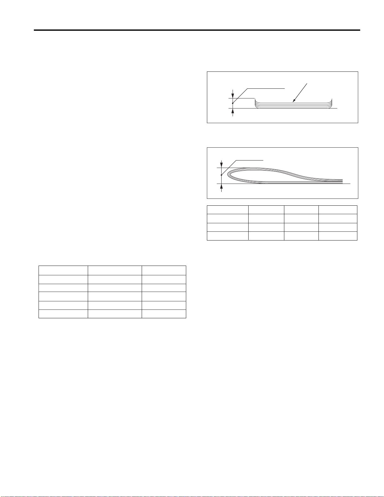
Amount of Curll
Copy paper (5 sheets)
Fold height
Original Pages
A3R, 11x17R
0 to 5
11 to 16
6 to 10
25mm or less
Not specified*
50mm or less
A4R, 8.5x11R
25mm or less
Not specified*
B4, 8.5x14R
25mm or less
50mm or less
Not specified*
Not specified*
Type
FS-108: Finishing device implementing offset colla-
tion, stapling, and subtray eject
FS-108B: Finishing device implementing offset colla-
tion, stapling, subtray eject, stapling and
folding, and folding
Functions
Type of Paper: Same as for the main body.
Paper Size: 11x17R, 8.5x11R, 8.5x11R, 8.5x11,
8.5x5.5R, 8.5x5.5, 5.5x8.5R.
8.5x5.5R, 5.5x8.5R are not possible in
staple mode. 8.5x1 1, 8.5x5.5R, 8.5x5.5,
5.5x8.5R, 5.5x8.5 are not available in
booklet mode.
Paper Stacking Capacity:
Subtray exit mode:
Maximum 200 sheets (same size sheets
only)
Non-Staple, Group, and Offset modes:
Maximum 1500 sheets (11x17R, 8.5x14R)
Maximum 3000 sheets (8.5x5.5R, 8.5x5.5,
8.5x11R, 8.5x11)
Maximum 500 sheets (5.5x8.5R, 5.5x8.5)
Staple Mode: Maximum 1000 sheets
Main Tray Capacity (same size sheets only)
Original Pages
2 to 9
10 to 20
21 to 30
31 to 40
41 to 50
Other than A3R, 11x17R
100 stacks
50 stacks
30 stacks
25 stacks
20 stacks
A3R, 11x17R
50 stacks
50 stacks
30 stacks
25 stacks
20 stacks
FS-108/108B
Paper curling: Maximum 10mm
Booklet mode fBooklet mode f
Booklet mode f
Booklet mode fBooklet mode f
olding leolding le
olding le
olding leolding le
vel (FS-108BM onlvel (FS-108BM onl
vel (FS-108BM onl
vel (FS-108B onlvel (FS-108BM onl
y)y)
y)
y)y)
(For 22 lb. paper or equivalent, same size sheets only)
* May be unfolded after exit, provided that fold state can
be easily restored.
Amount of sort
off-setting: 30mm (when offsetting/grouping)
Tray: Main tray
Subtray
Booklet tray (FS-108B only)
Booklet Mode (FS-108B only):
• Stapling and folding + folding
20 booklets of 5 folded sheets each (20 pages/booklet; eq. to 400 pages)
• Folding
33 booklets of 3 folded sheets each (12 pages/booklet; eq. to 396 pages)
FS-1
Page 10
FS-108/108B
Staple Mode
Number of pages
which may be stapled:
50 sheets maximum* (22 lb. highquality paper, 5mm and below)
* Maximum sheets can be set to 45, 40, or 35 in accor-
dance with paper quality and thickness.
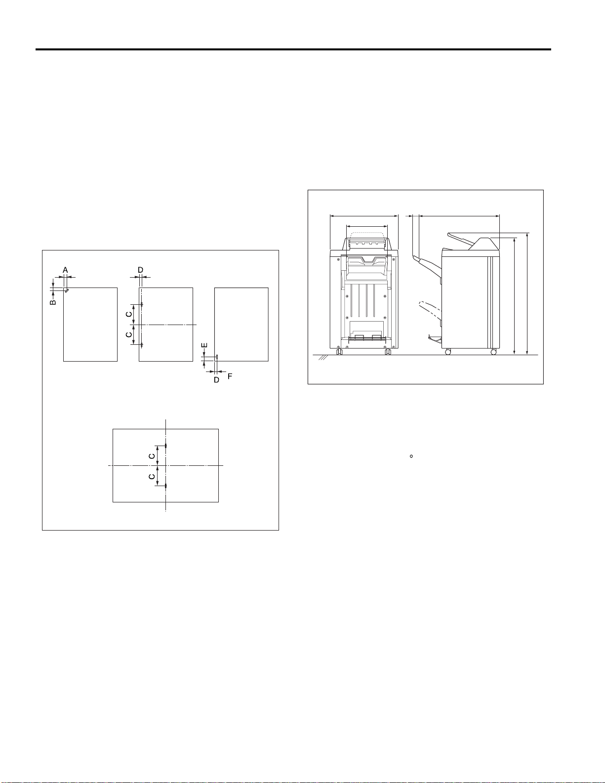
Staple position: A = 8.5mm±3mm
(adjustment possible)
B = 8.5mm±3mm
C = 82.5mm±3mm
D = 8.5mm±3mm
(adjustment possible)
E = 14mm±3mm)
Machine Data
Power Source:
24 VDC, 5 VDC (supplied from the
main body)
Maximum Power
Consumption: 100VA
Weight:
FS-108: Approximately 120 lb.
FS-108B: Approximately 175 lb.
External Dimensions:
85
367
781656
1095
1151
Single staple (rear) Two staples Single staple
Booklet mode (stapling and folding)
Staple capacity:Staple capacity:
Staple capacity: 5000 staples/car tridge
Staple capacity:Staple capacity:
(FS-108B only)
@@@(front)
Booklet Mode (FS-108B only)
Stapling-and-folding:
Maximum 16 sheets (22 lb. high-quality paper)
Maximum 15 sheets (22 lb.
+ 1 sheet (53 lb.
high-quality paper)
Folding: Maximum 3 sheets (22 lb. high-quality paper)
high-quality paper)
Maintenance
Maintenance: Same as the main body.
Service Life: Same as main body.
Machine Operating Environment
Temperature: 50 to 86 F
Humidity: 10 to 80% RH
These specifications are subject to change without notice.
Option
PI-108 (Sheet feeder)
FS-2
Page 11
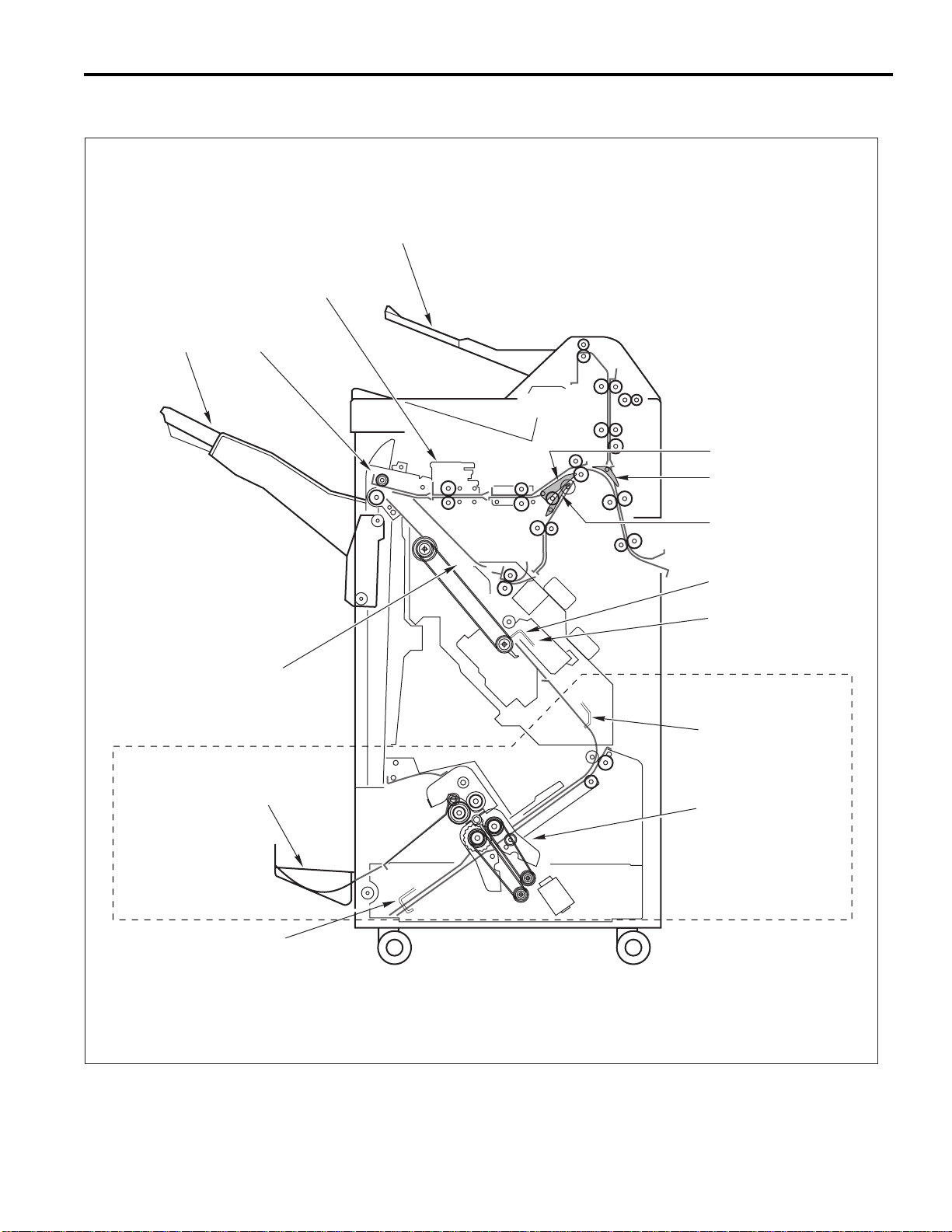
CENTER CROSS SECTION
Sub-tray
Shift Unit
Main Tray Paper Exit Unit
FS-108/108B
Gate
Sub-tray Gate
Stacker Unit
Booklet T ra y
Folding Stopper
By-pass Gate
Flat-Stapling Stopper
Stapler Unit
Area within dotted lines:
FS-108BM only
Stapling and
Folding Stopper
Folding Unit
FS-3
Page 12
FS-108/108B
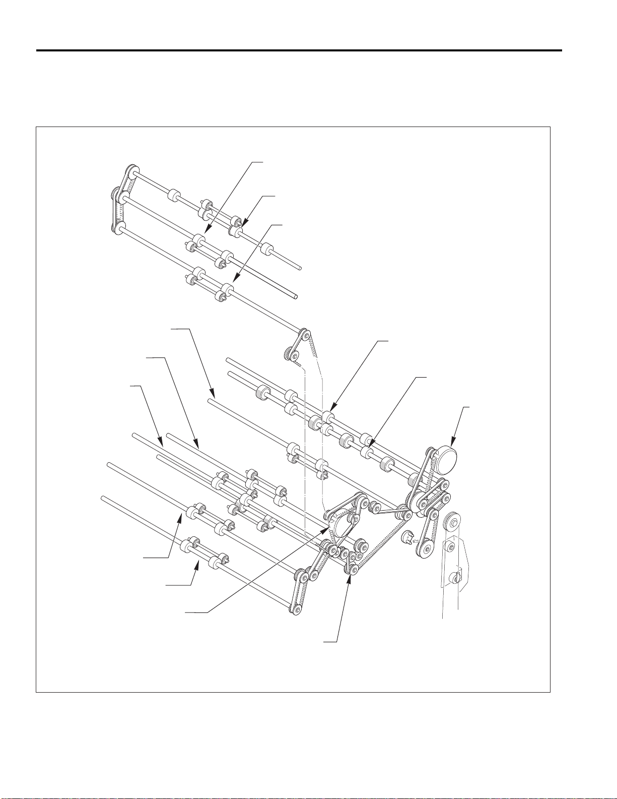
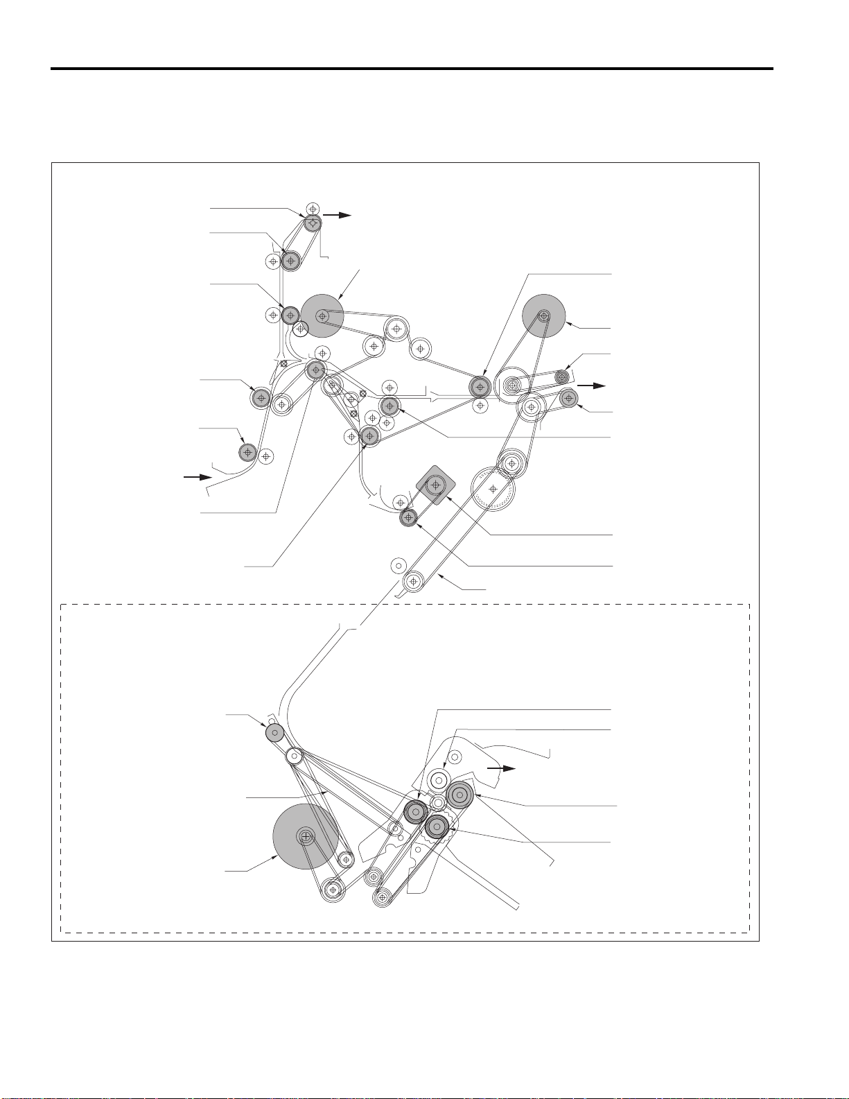
DRIVE SYSTEM DIAGRAM
Paper Conveyance Drive
Sub-tray Paper Exit Roller B
Conveyance Slide Shaft
Sub-tray Paper Exit Roller C
Sub-tray Paper Exit Roller A
Nip Paper Exit Roller
Conveyance Roller D
Conveyance Roller C
Conveyance Roller B
Conveyance Roller A
M1 (FNS Conveyance)
Paper Exit Roller
M7 (Paper Exit
Roller)
Intermediate Conveyance Roller
FS-4
Page 13
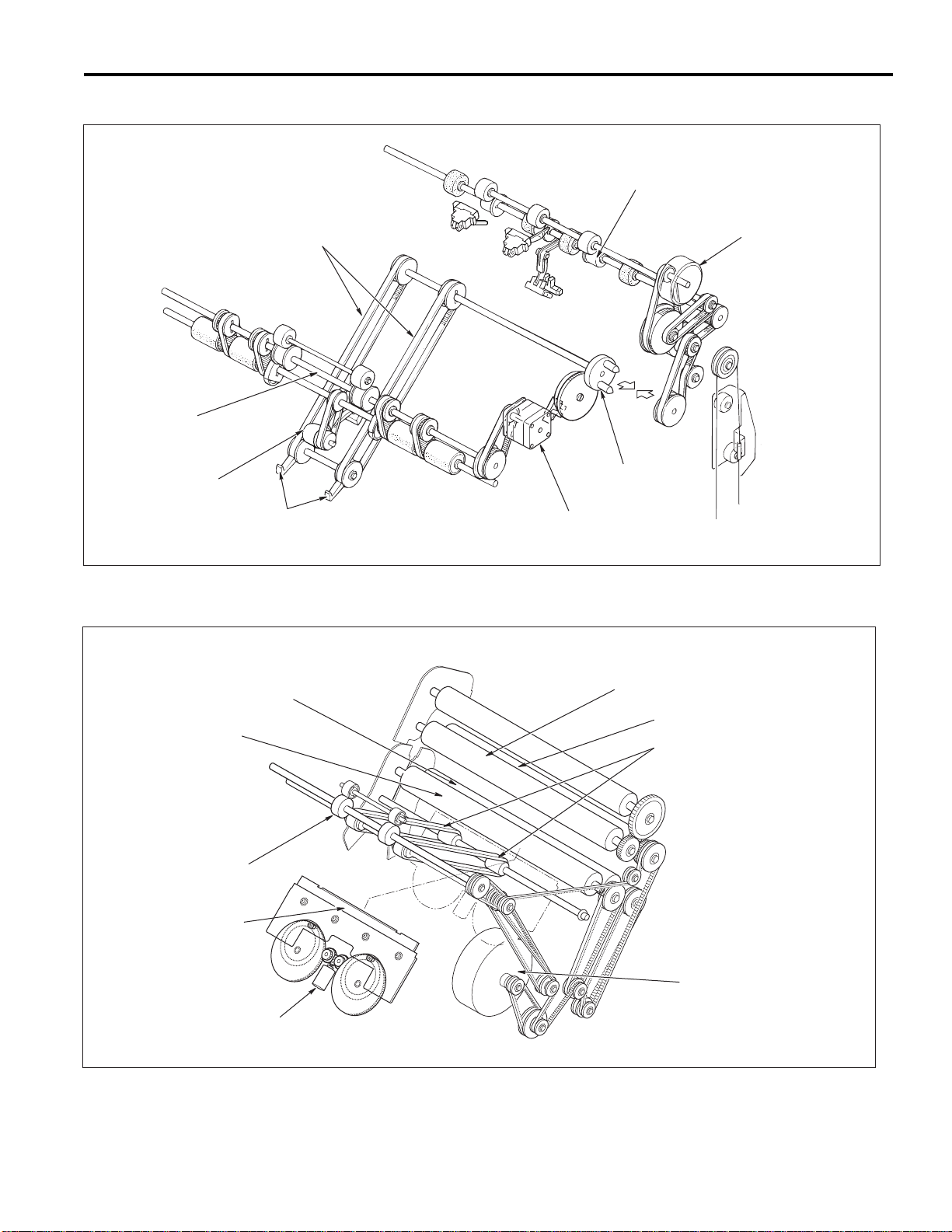
Stacker Drive
FS-108/108B
Paper Exit Roller
Paper Exit Belts
Stacker Entrance Roller
Swivel Roller
Paper Exit Arms
Folding Drive (FS-108BM only)
M7 (Paper Exit Roller)
Pulley
M13 (Stacker Entrance)
Folding Roller B
Folding Roller A
Folding Conveyance Roller
Folding Knife
M19 (Folding Knife)
Pressure Roller A
Pressure Roller B
Folding Conveyance Belts
M20 (Folding Conveyance)
FS-5
Page 14
FS-108/108B
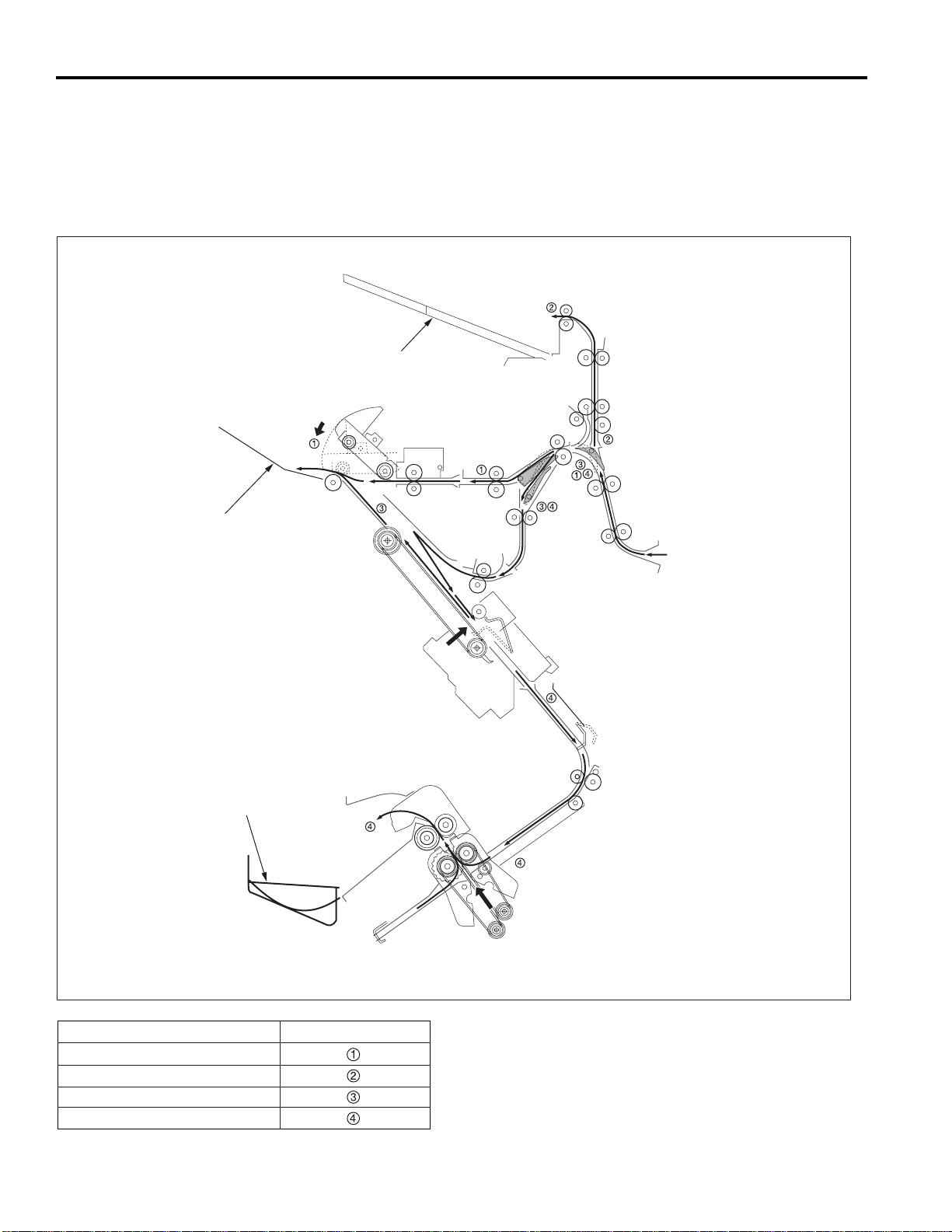
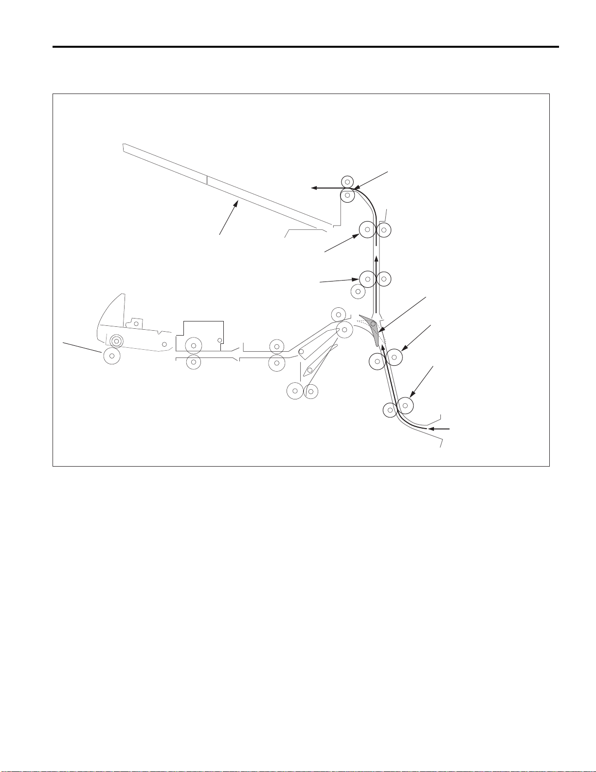
PAPER CONVEYANCE PATH
Paper Conveyance Path
The finisher provides four paper paths, as shown in the diagram below.
Face up and face down inversion is handled by at the main body side by the main body’s exit page inverter.
Sub-tray
Main T ra y
Booklet T ra y
Finishing
Sort, Group, Non-sort mode
Sub-tray mode
Staple mode
Booklet mode (FS-108BM only)
Paper Conveyance Paths
FS-6
Page 15
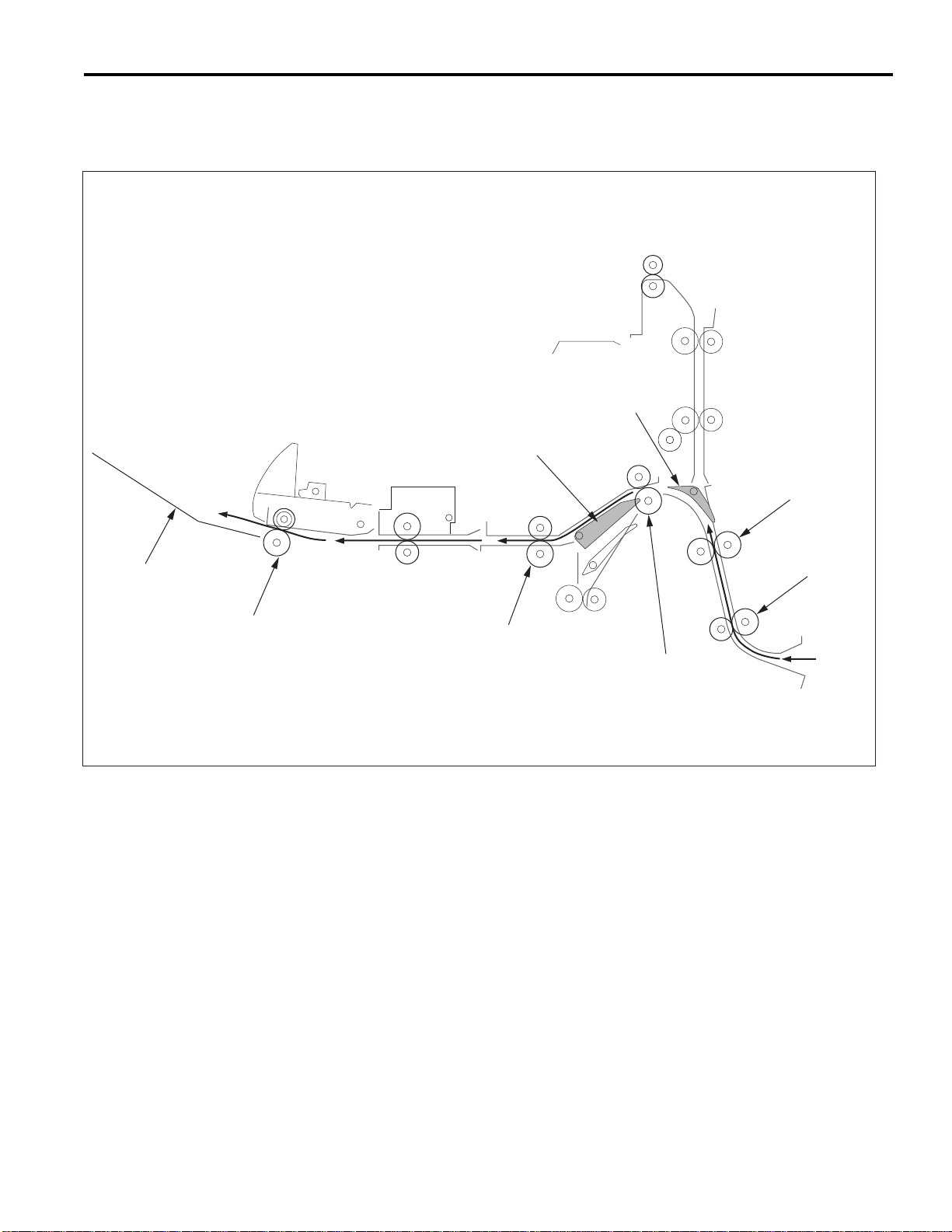
Non-Sort Mode
Exit to main tray
A paper exited from the main body is conveyed and exited to the main tray.
FS-108/108B
Sub-tray Gate
Gate
Conveyance Roller B
Main T ra y
Paper Exit Roller
Conveyance Roller A
Conveyance Roller D
Conveyance Roller C
FS-7
Page 16
FS-108/108B
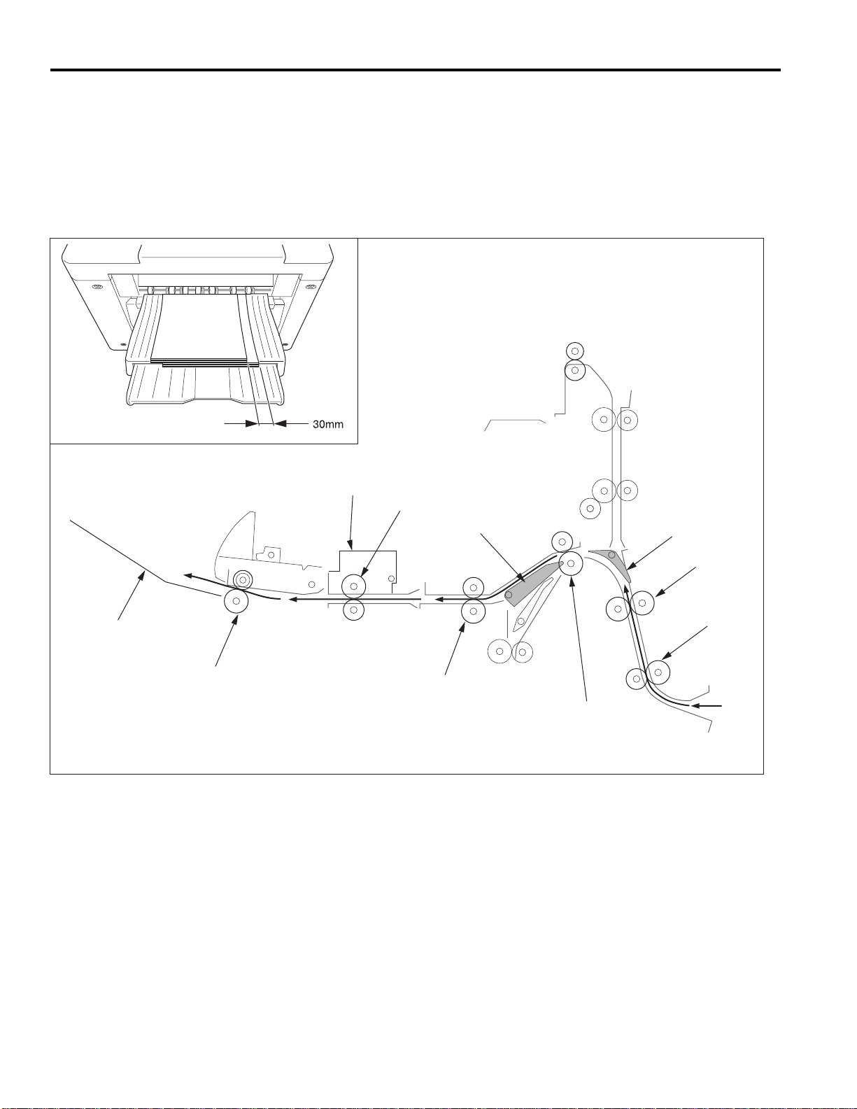
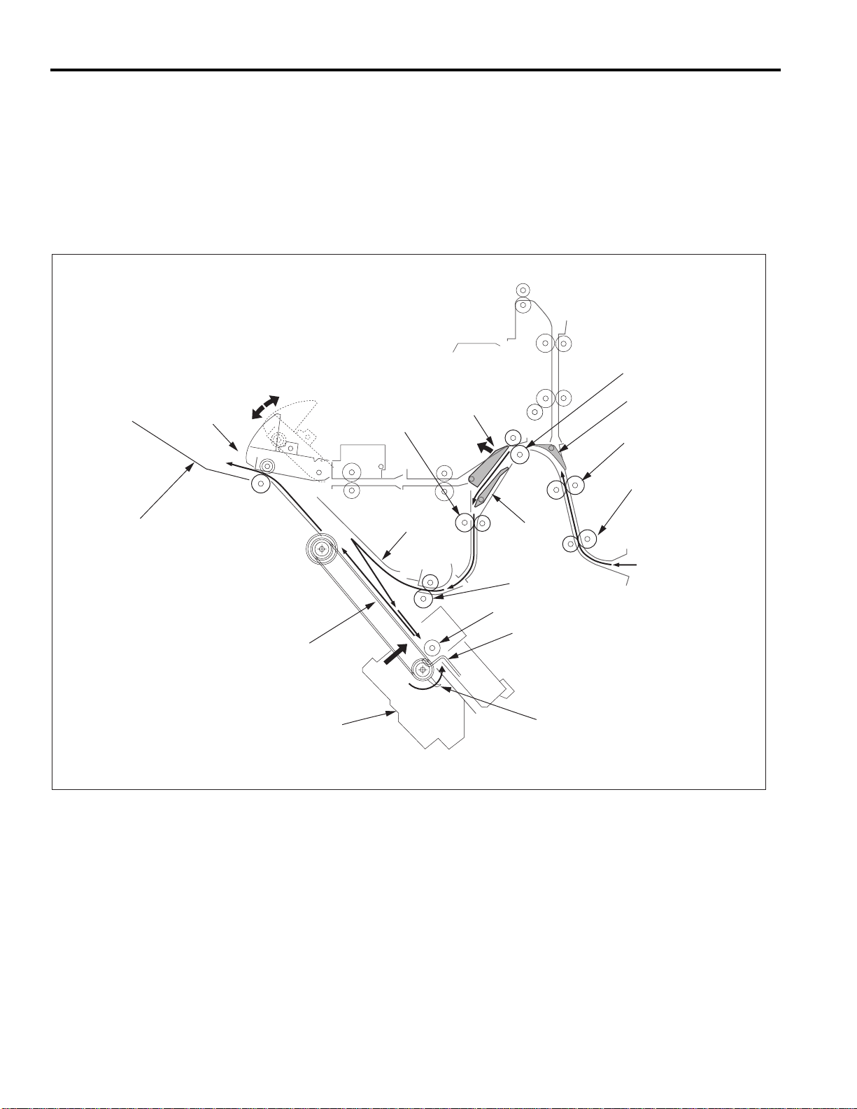
Sort, Group Mode
Exit to the main traExit to the main tra
Exit to the main tra
Exit to the main traExit to the main tra
Paper exited from the main body is conveyed and exited to the main tray. This mode has an offset function that allows each
page of the even numbered sets to be exited with the paper shifted 30mm to the rear.
Off-set Function
(1) The odd numbered pages are exited to the main tray with the image side face down.
(2) The even numbered pages are shifted 30mm to the rear by the conveyance slide shaft of the shift unit and then exited to
the main tray.
yy
y
yy
Main T ra y
Paper Exit Roller
Shift Unit
Conveyance Slide Shaft
Conveyance Roller D
Gate
Sub-tray Gate
Conveyance Roller B
Conveyance Roller A
Conveyance Roller C
FS-8
Page 17
Subtray Mode
The subtray gate opens. Paper exited from the main body is conveyed and exited to the subtray.
Sub-tray Paper Exit Roller C
Sub-tray
Sub-tray Paper Exit Roller B
Sub-tray Paper Exit Roller A
FS-108/108B
Sub-tray Gate
Conveyance Roller B
Conveyance Roller A
FS-9
Page 18
FS-108/108B
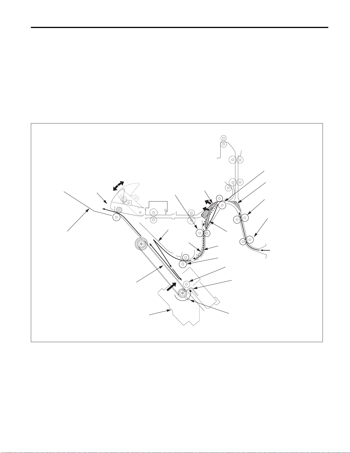
Staple Mode
(1) The gate switches to the staple mode.
(2) For 8.5x11R paper and above, the paper exit opening opens.
(3) The first set of paper is conveyed and stacked.
1) The stacker section roller sends the paper to the flat stapling stopper and the paper is lined up in the lengthwise
direction.
2) The upper alignment plate lines up paper in the widthwise direction.
3) Paper is stapled.
4) The first set is conveyed by the paper exit arm and exited to the main tray.
Paper Exit Opening
Conveyance Roller C
Main Tray
First Stapled Set
Paper Exit Belt
Stapler Unit
Intermediate Conveyance
Roller
Alignment Plate
/Upper
Gate
Sub-tray Gate
Conveyance Roller B
Conveyance Roller A
By-pass
Gate
Stacker Entrance
Roller
Swivel Roller
Flat-Stapling Stopper
Paper Exit Arm
FS-10
Page 19
FS-108/108B
(4) The second and subsequent sets of paper are conveyed and stacked.
1) The first page stops in the stacker entrance with the bypass gate opened. The stacker entrance roller stops to wait for
the previous stack to be exited.
2) The bypass gate is closed and the second page is stacked on top of the first.
3) Once the previous stack has exited, the stack entrance roller rotates and the first and second pages are simultaneously
sent to the stacker.
* The above steps (1) to (3) are for paper to a maximum of 8.5x11 size.
4) The stacker section roller sends the paper to the flat-stapling stopper and the paper is lined up in the lengthwise
direction.
5) The upper alignment plate lines up paper in the widthwise direction.
6) When all paper is conveyed to the stacker, the paper is stapled.
7) The second and subsequent sets are conveyed by the paper exit arm and the paper is exited to the main tray.
Paper Exit Opening
Conveyance Roller C
Second Stapled Set
Main Tray
Intermediate
Conveyance Roller
Paper Exit Belt
Stapler Unit
Alignment Plate/Upper
Second Sheet
Sub-tray Gate
Gate
Conveyance Roller B
Conveyance Roller A
By-pass
Gate
First Sheet
Stacker Entrance Roller
Swivel Roller
Flat-Stapling Stopper
Paper Exit Arm
FS-11
Page 20
FS-108/108B
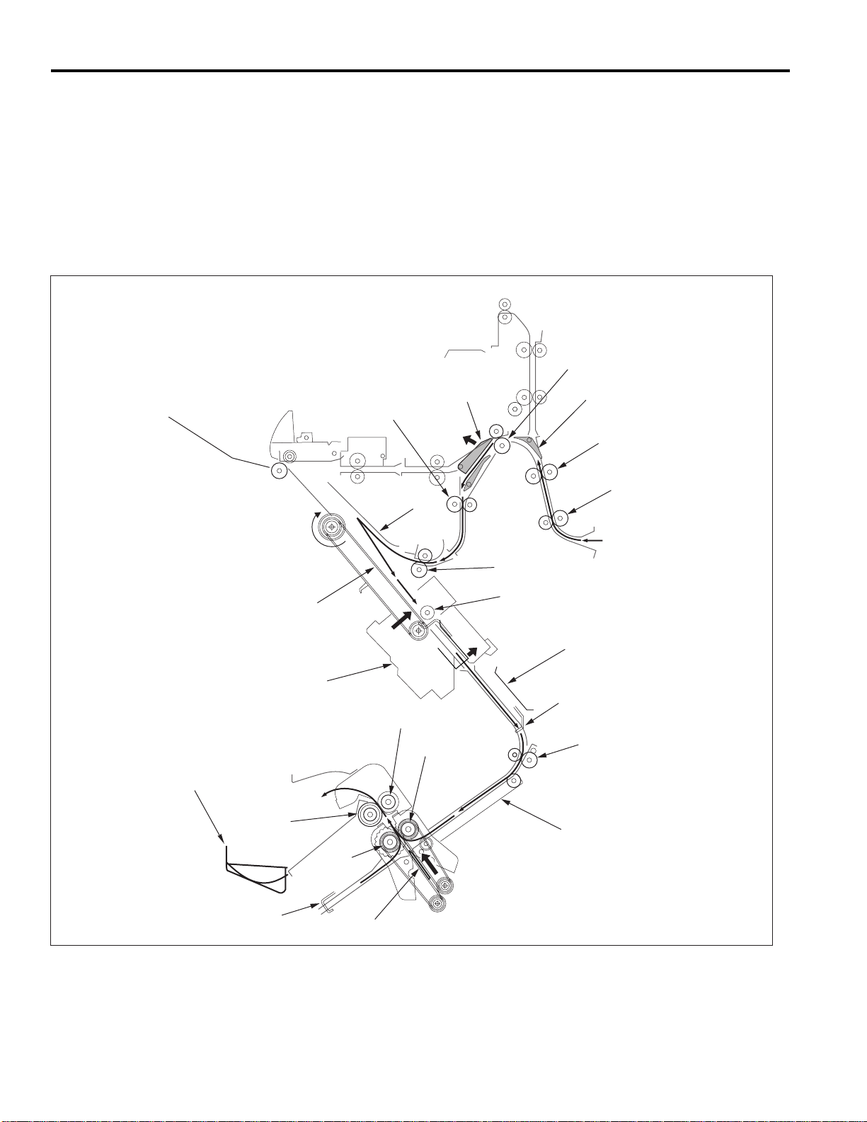
Booklet Mode (FS-108BM only)
(1) The gate switches to the staple mode.
(2) The paper exit opening opens.
(3) The paper is conveyed and stacked.
(4) The stacker section roller sends the paper to the stapling and folding stopper and the paper is lined up in the lengthwise
direction.
(5) The upper and lower alignment plate lines up paper in the widthwise direction.
(6) If stapling and folding has been selected, staple the stack.
(7) Release the stapling and folding stopper and convey the stack to the folding unit by the paper exit belt.
(8) Convey the stack up to the folding stopper, fold it with the folding knife, and eject to the booklet tray.
Conveyance Roller C
Booklet Tray
Intermediate Conveyance Roller
Upper
Alignment Plate
Paper Exit Belt
Stapler Unit
Gate
Pressure Roller A
Folding Roller A
Sub-tray Gate
Conveyance Roller B
Conveyance Roller A
Stacker Entrance Roller
Swivel Roller
Alignment Plate/Lower
Stapling and Folding stopper
Folding Conveyance Roller
Pressure
Roller B
Folding Stopper
Folding Conveyance Belt
Folding
Roller B
Folding Knife
FS-12
Page 21
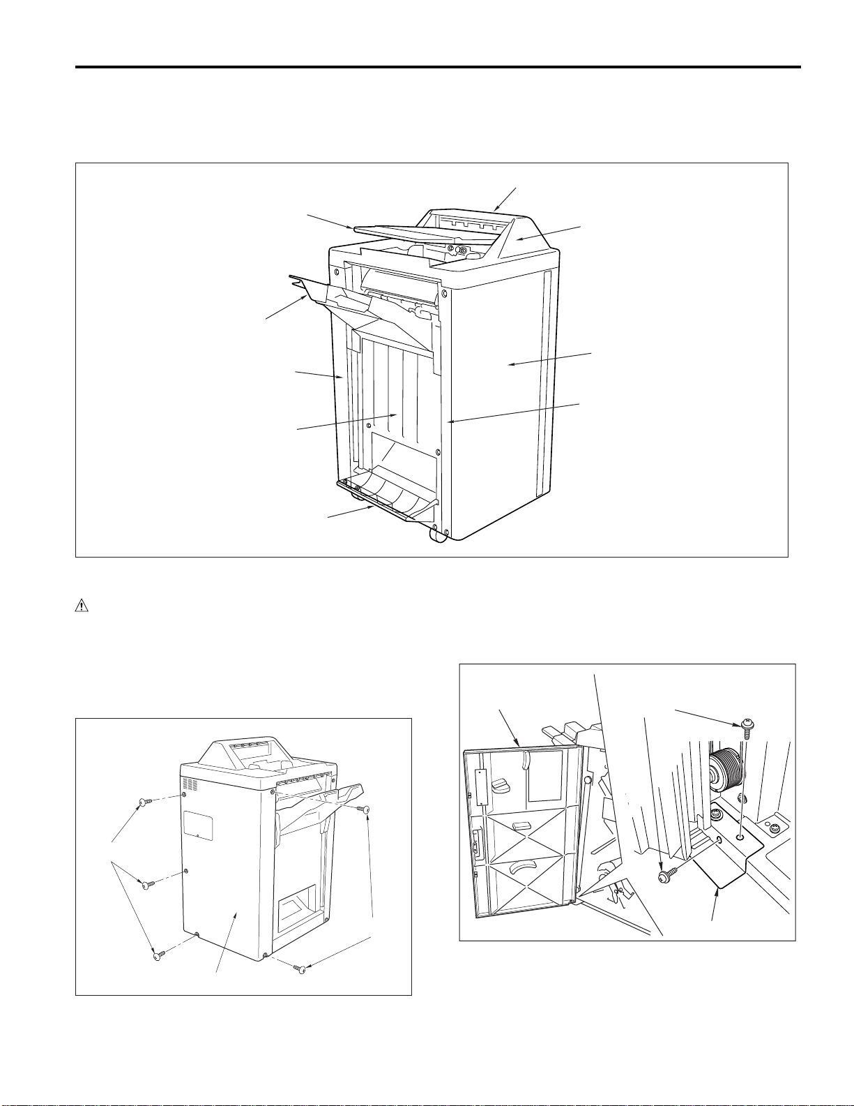
EXTERNAL SECTION
Screws
Hinge
Front Cover
Composition (FS-108/FS-108BM)
FS-108/108B
Paper Exit Cover
Sub-tray
Main T ra y
Rear Cover
Paper Exit Stopper Plate
Booklet T ra y
Disassembly and Reassembly
CAUTION: Be sure that the power cord has been un-
plugged from the outlet.
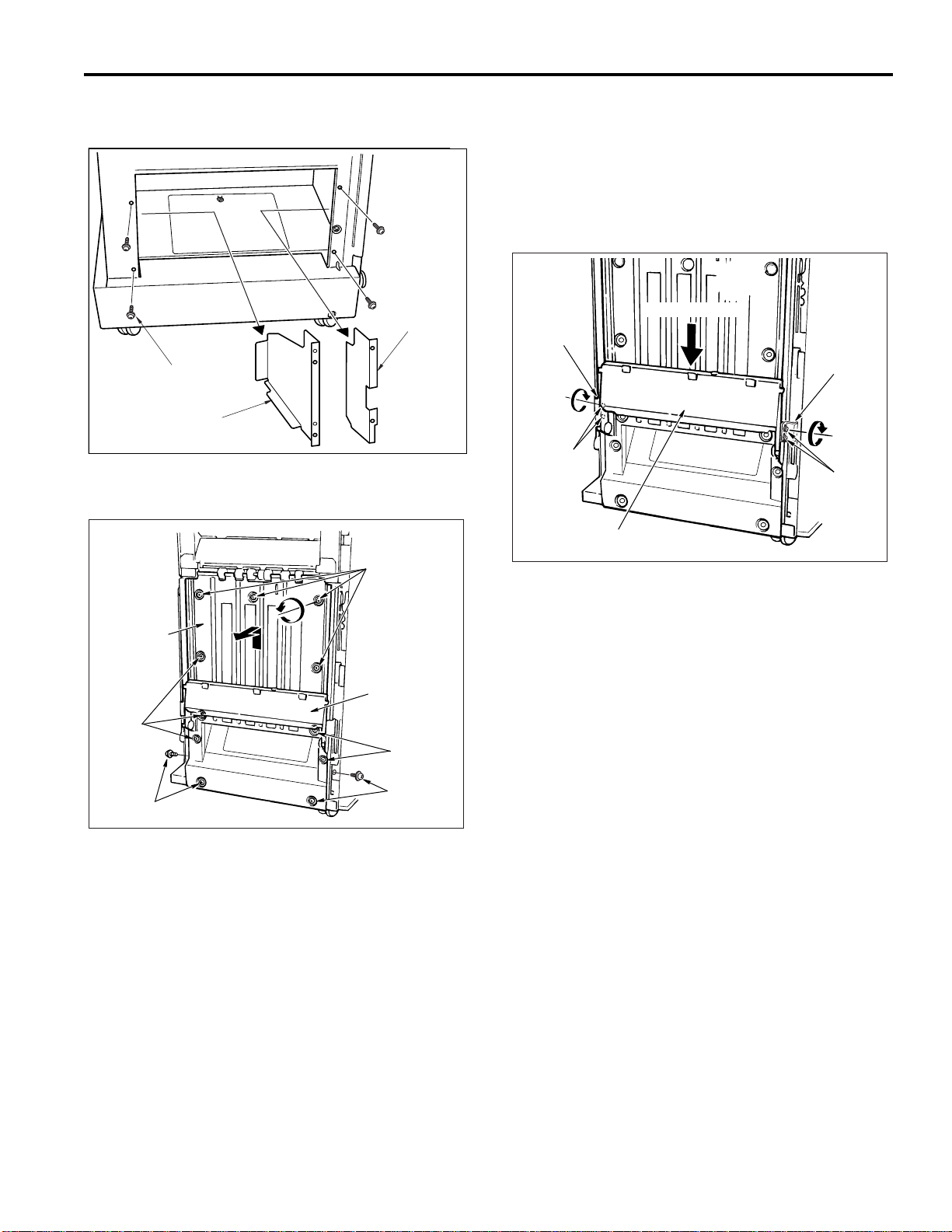
1. Removing and Reinstalling the Rear Cover
a. Procedure
(1) Remove the 5 set screws holding the rear cover in
place, and take off the cover.
Top Cover
Front Cover
Front Side Cover
2. Removing and Reinstalling the Front Cover
a. Procedure
(1) Open the front cover.
(2) Remove the 2 set screws holding the bottom hinge in
place, and take off the front cover.
Screws
(2) Reinstall the rear cover in the opposite sequence to
removal.
Screws
Rear Cover
(3) Reinstall the front cover in the opposite sequence to
removal.
FS-13
Page 22
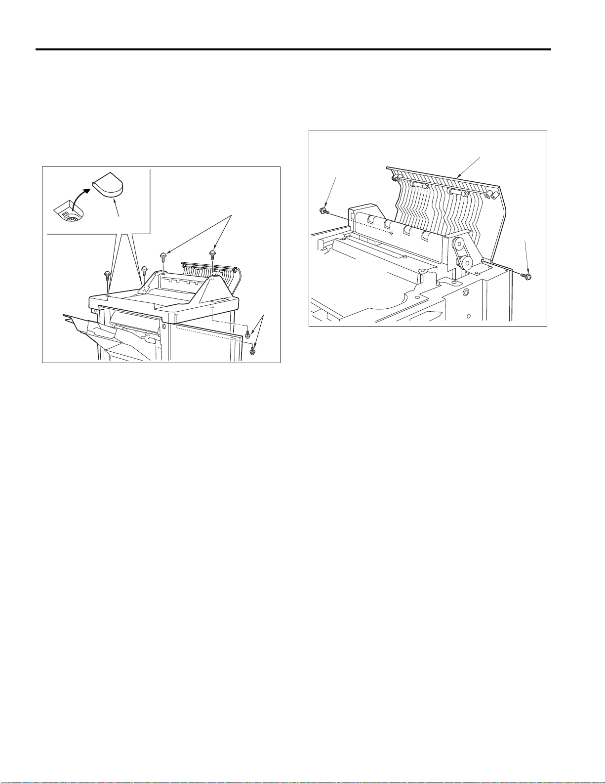
FS-108/108B
Screw
Paper Exit Cover
Screw
3. Removing and Reinstalling the Top Cover
a. Procedure
(1) Remove the subtray.
(2) Open the paper exit cover.
(3) Remove the two caps.
(4) Open the front cover.
(5) Remove the 6 set screws holding the top cover in
place, and take off the cover.
Screws
Cap
4 Removing and Reinstalling the Paper Exit Cover
a. Procedure
(1) Remove the top cover.
(2) Remove the 2 set screws holding the paper exit cover
in place, and take off the paper exit cover.
Screws
(3) Reinstall the paper cover in the opposite sequence to
removal.
(6) Reinstall the top cover in the opposite sequence to
removal.
FS-14
Page 23
FS-108/108B
Front Side
Cover
Screws
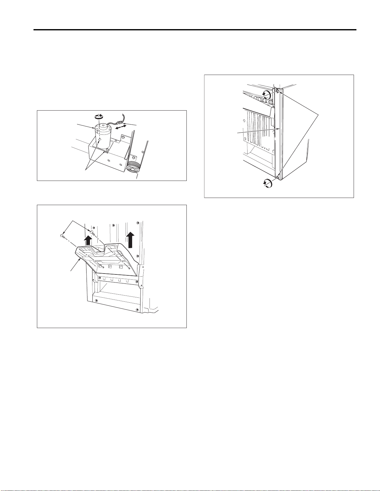
5. Removing and Reinstalling the Main Tray
a. Procedure
(1) Remove the rear cover.
(2) Detach the connector and remove the 2 set screws
holding motor M3 (tray up-down motor) in place. Remove M3.
CAUTION: Support the main tray with your hand when
removing M3.
M3 (Tray Up-Down)
Screws
Connector
(3) Remove the 2 set screws holding the main tray in
place, and lift the main tray up and off.
Screws
6. Removing and Reattaching the Front Side Cover
a. Procedure
(1) Remove the 2 set screws holding the front side cover
in place, and take off the front side cover.
(2) Reinstall the front side cover in the opposite sequence
to removal.
Main Tray
(4) Reinstall the main tray in the opposite sequence to
removal.
FS-15
Page 24
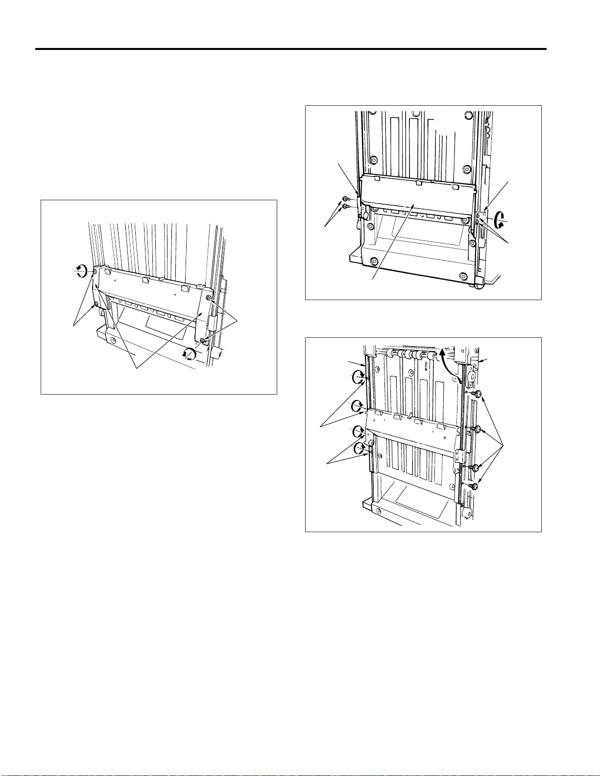
FS-108/108B
Screws
Screws
Up-Down Stay
Wire Bracket
Wire Bracket
7. Removing and Reinstalling the Paper Exit Stopper Plate
a. Procedure
(1) Remove the following parts.
• Rear cover
• Main tray
• Booklet tray
• Front cover
• Front side cover
(2) Remove the 4 set screws holding the left and right
up-down covers in place, and remove these two covers.
Screws
Screws
Up-Down Covers
(3) Remove the 4 set screws from the front and rear wire
brackets (two screws at each bracket), and then remove the up-down stay.
(4) Remove 8 set screws and take off the front and rear
auxiliary side up down plates.
Rear Auxiliary
Side-Up-Down
Plate
Front Auxiliary
Side-Up-Down
Plate
Screws
Screws
Screws
FS-16
Page 25
FS-108/108B
Press down
Wire Bracket
Wire Bracket
Screws
Screws
Up-Down Stay
(5) Remove the two plates (front and back plates) at the
booklet exit.
Plate
Screw
Plate
(6) Remove 13 more set screws, and take off the paper
exit stopper.
(7) Remove the up-down stay. (See “Removing and re-
attaching the up-down stay”.)
(8) Reinstall the stopper in the opposite sequence to re-
moval. But note the following caution.
CAUTION:Be sure to press down on the up-down stay
while tightening the 4 screws for the wire brackets.
Screws
Paper Exit
Stopper Plate
Up-Down Stay
Screws
Screws
Screws
Screws
FS-17
Page 26
FS-108/108B
CONVEYANCE SECTION
Composition
Sub-tray Paper Exit Roller C
Sub-tray Paper Exit Roller B
FS-108/FS-108BM Rear
Sub-tray Paper Exit Roller A
Conveyance Roller B
Conveyance Roller A
Conveyance Roller C
Intermediate Conveyance Roller
M1 (FNS Conveyance)
Conveyance Slide Shaft
M7 (Paper Exit Roller)
Nip Paper Exit Roller
Paper Exit Roller
(Sponge Roller)
Conveyance Roller D
M13 (Stacker Entrance)
Stacker Entrance Roller
Paper Exit Belt
Area within dotted lines: FM-108BM only
Folding Conveyance Roller
Folding Conveyance Belt
M20 (Folding Conveyance)
Folding Roller A
Pressure Roller A
Pressure Roller B
Folding Roller B
FS-18
Page 27
FS-108/108B
Link Mechanism
M2 (Roller Shift)
M2 (Roller Shift)
Paper exit direction
Slide Shaft
Link Mechanism
Slide Shaft
30mm towards the direction
of the back side
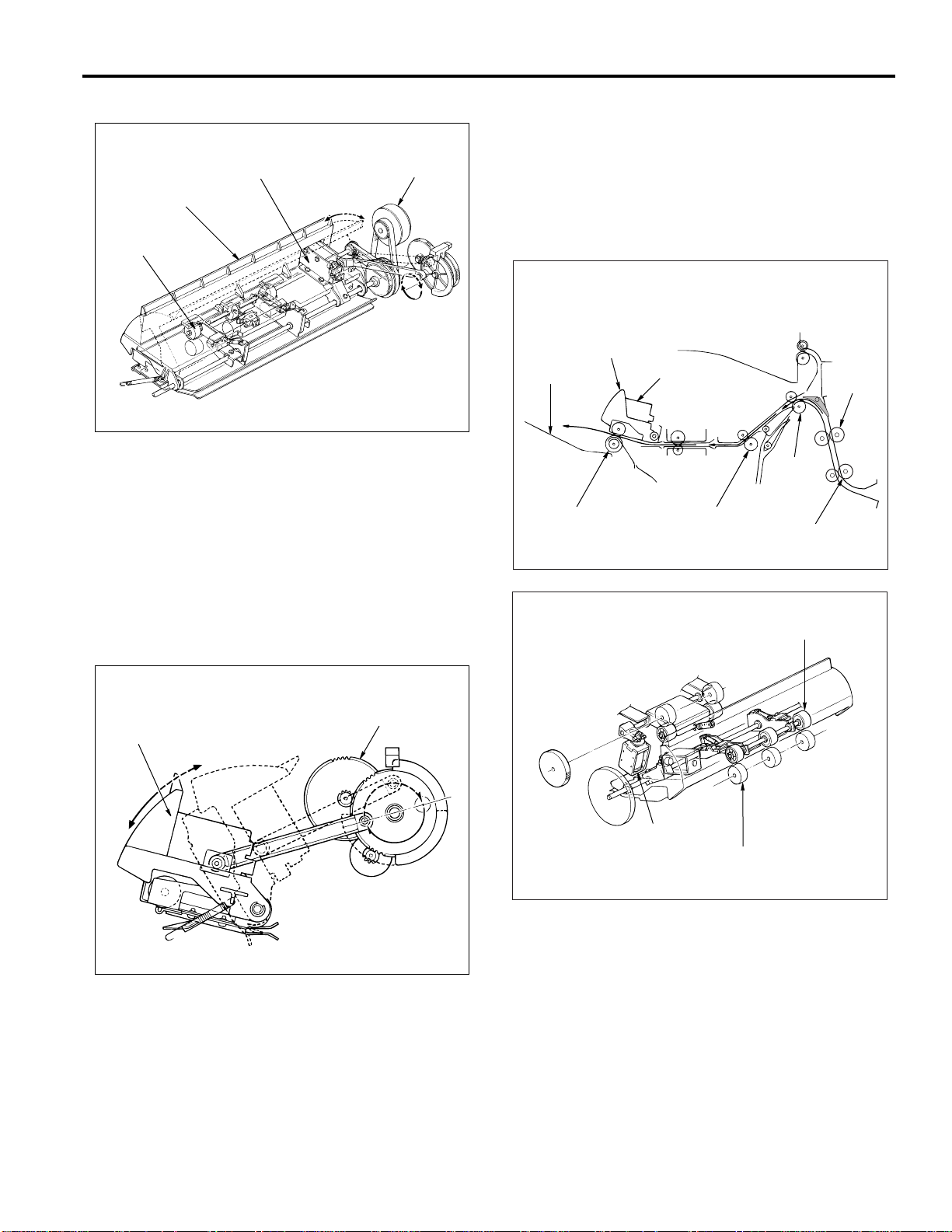
Mechanisms
1. Paper Conveyance
Paper conveyance is carried out by conveyance rollers A,
B, C, and D; the intermediate conveyance roller; the conveyance slide shaft; and subtray paper exit rollers A, B,
and C. These components are driven by M1 (FNS conveyance) by means of a timing belt.
Stacking is implemented by the stacker entrance roller and
the swivel roller. These rollers are driven by the M13
(stacker entrance) by means of a timing belt.
Ejection to the main tray (following staple processing) is
implemented by the stacker paper exit belt arm and the
paper exit roller. These components are driven by the M7
(paper exit).
Ejection to the booklet tray is implemented by the folding
conveyance roller, the folding conveyance belt, the folding knife, folding rollers A and B, and pressure rollers A
and B. The folding knife is driven by M19 (folding knife).
The conveyance belt, folding rollers, and pressure rollers
are driven by the M20 (folding conveyance) by means of a
timing belt.
2. Paper Path Switching
Gate
Sub-tray Gate
SD2
(Sub-tray Paper Exit)
By-pass Gate
SD5 (By-pass)
SD1 (Gate)
Path switching is carried out by the gate, the subtray gate,
and the bypass gate. Each of these is controlled by the
ON/OFF action of a corresponding solenoid: SD1 (gate),
SD2 (subtray paper exit), and SD5 (bypass), respectively .
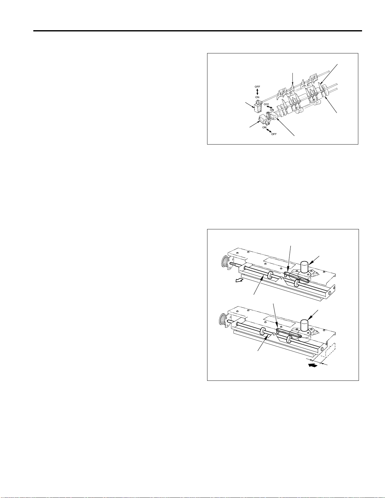
3. Shift Unit Sort Shift Operation
(1) Paper entering the shift unit is fed toward the paper
exit direction by the action of the slide shaft.
(2) Driving by M2 (roller shift) causes the linkage to shift
the slide shaft and paper 30mm toward the rear.
FS-19
Page 28
FS-108/108B
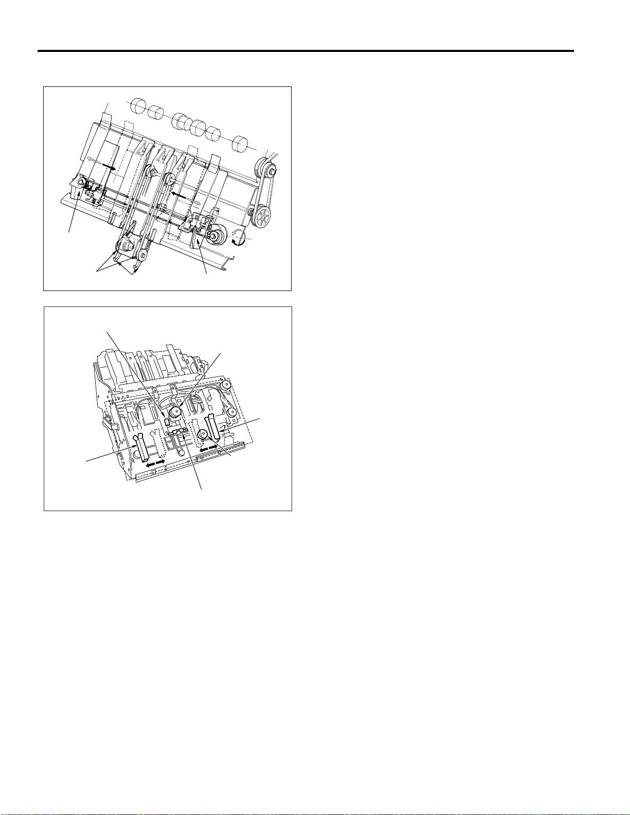
4. Stacker Unit
Alignment Plate/
Upper
Paper Exit
Belts
Paper Exit Arms
Alignment Plate/Upper
FS-108BM Only
M17 (Stapling and Folding Stopper Release)
M14
(Stapling and Folding Stopper)
M5
(Alignment
Plate/Upper)
Paper Alignment (Staple Mode (Flat Stapling))
Sheets conveyed into the stacker are aligned by the oscillation of the (front and rear) alignment plates/upper. The
alignment plates/upper are driven by M5 (alignment plate/
upper).
Paper Alignment (Booklet Mode (FS-108BM only))
Sheets conveyed into the stacker are aligned by the movement of the (front and rear) alignment plates/upper and
the (front and rear) alignment plates/lower. The alignment
plates/upper are driven by M5 (alignment plate/upper); the
alignment plates/lower are driven by M15 (alignment plate/
lower). The stapling and folding stopper is moved by M14
(stapling and folding stopper) and is released by M17 (stapling and folding stopper release).
Paper Exiting
Stapled paper is sent to the paper exit by the paper exit
arm. The paper exit belt is driven by M7 ( paper exit roller).
Feeding to the Folding Unit (FS-108BM only)
M17 (stapling and folding stopper release) releases the
stapling and folding stopper and feeds the paper into the
folding unit.
Alignment Plate/
Lower
Alignment
Plate/Lower
M15
(Alignment Plate/
Lower)
Stapling and Folding Stopper
FS-20
Page 29
FS-108/108B
Conveyance
Roller B
Conveyance Roller A
Conveyance
Roller C
Conveyance Roller D
Paper Exit Rolle
r
Main T ra y
Paper Exit Opening
SD4 (Paper Exit Opening)
Nip Roller
Paper Exit Roller
SD4 (Paper Exit
Opening)
5. Paper Exit Opening Unit
M8
SD4 (Paper Exit Opening)
Paper Exit Opening
Nip Roller
(Paper Exit Opening)
a. Staple Mode and Booklet Mode Operation for
Paper Sizes 8.5x11R and Above
Because paper of this size juts out from the stacker, the
paper exit opening is held open from the start of copying
until the completion of stapling.
c. Pressure of the Paper Exit Roller
The paper exit roller turns more slowly than the conveyance rollers (A, B, C, and D), and remains unengaged by
the nip roller except during ejection.
When paper reaches the paper exit opening, the paper
exit roller is engaged by the nip roller and the paper is
ejected to the main tray. Engagement and release is controlled by SD4 (paper exit opening).
b. Paper Exit of the Staple Mode (Flat Stapling)
Upon completion of stapling, the paper exit closes, and
the paper is grasped and ejected to the main tray. The
opening and closing of the paper exit is controlled by M8
(paper exit opening).
M8 (Paper Exit Opening)
Paper Exit Opening
Open
Close
FS-21
Page 30
FS-108/108B
Sponge Roller
Match
Match
6. Folding by the Folding Unit (FS-108BM only)
Paper is conveyed to the folding stopper by the action of
the folding conveyance roller and the folding conveyance
belts, and is then folded by the action of the folding knife
and the folding rollers. The folding conveyance roller, the
folding conveyance belts, the folding rollers, and the pressure roller are driven by M20 (folding conveyance). M18
(folding stopper) drives the folding stopper. M19 (folding
knife) drives the folding knife.
M20
(Folding Conveyance)
Folding Rollers
M18
(Folding
Stopper)
Folding Conveyance Belts
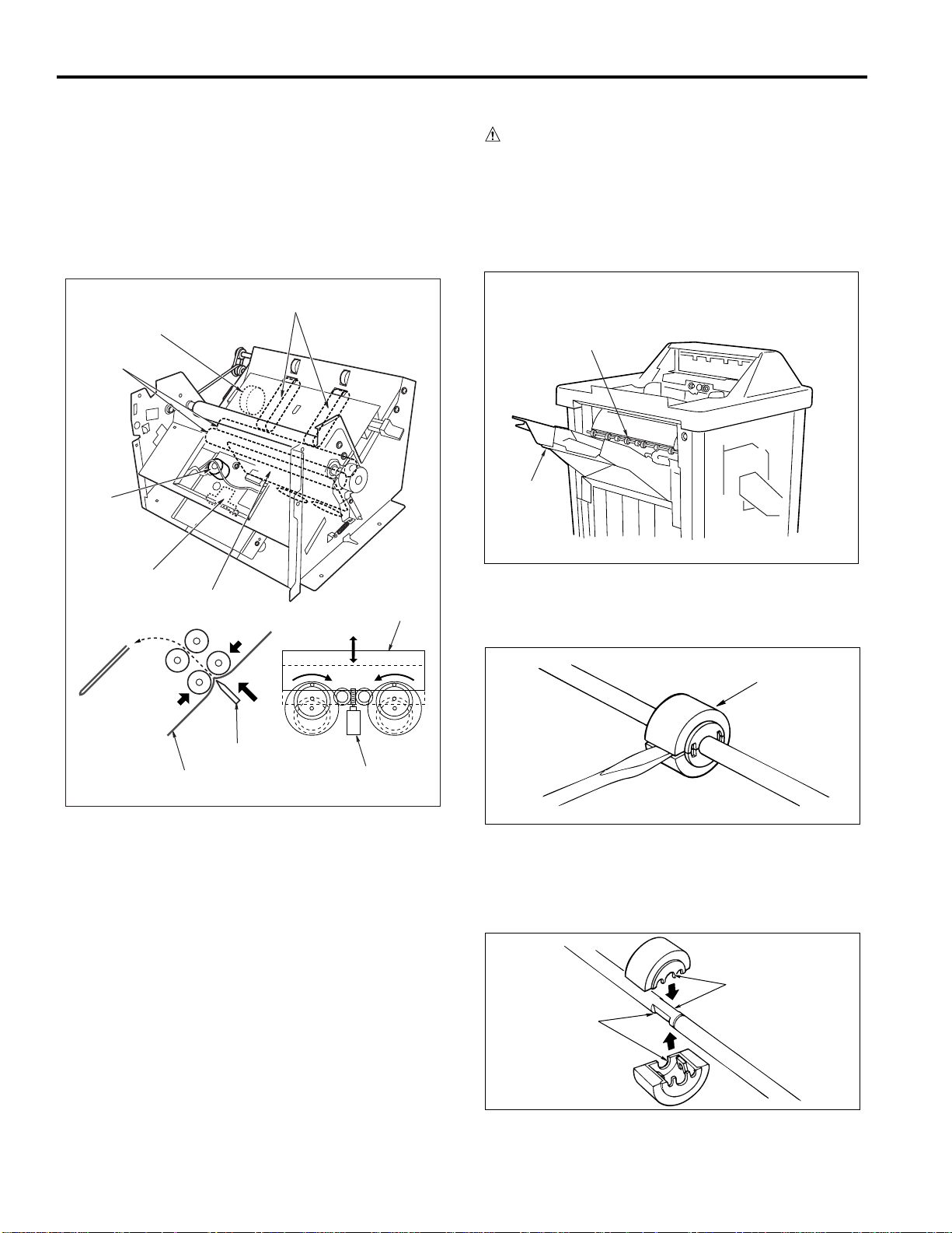
Disassembly and Reassembly
CAUTION: Be sure that the power cord has been un-
plugged from the outlet.
1. Replacing a Paper Exit Roller (Sponge Roller)
a. Procedure
(1) Run the copier in mode 47 (code 75-06) to lower the
main tray.
Sponge Roller
Main Tray
Folding
Paper-End Stopper
Paper
Folding Knife
Folding Knife
Folding Knife
M19 (Folding Knife)
(2) Insert the end of a screwdriver into the slot in the
sponge roller, and twist the screwdriver to pry the
roller off.
(3) Take the two halves of the new sponge roller and
align their indentations with the indentations on the
roller shaft.
(4) Press the two halves of the roller together until the
click into place.
FS-22
Page 31

FS-108/108B
Clamps
Wirings
M2 (Roller Shift) Connector
PS18 (Roller Shift HP)
Connector
Clamp Screw
Screws
Ground Wire
Fixing Screw
Shift Unit
Screws
2. Replacing an Intermediate Conveyance Roller (Sponge
Roller)
a. Procedure
(1) Open the front cover and pull out the stacker/stapler
unit.
(2) Insert the end of a screwdriver into the slot in the
sponge roller, and twist the screwdriver to pry the
roller off.
Sponge Rollers
3. Removing and Reinstalling the Shift Unit
a. Procedure
(1) Remove the following parts.
• Rear cover
• Top cover
• PI-108 (if installed)
(2) Detach the M2 (roller shift) and PS18 (roller shift HP)
connectors.
(3) Remove the wiring from the three clamps.
Sponge Roller
(3) Take the two halves of the new sponge roller and
align their indentations with the indentations on the
roller shaft.
(4) Press the two halves of the roller together so that
they click into place.
Match
Match
(4) Remove the ground wire fixing screw.
(5) Remove the clamp set screw.
(6) Remove 4 more set screws (see illustration).
FS-23
Page 32

FS-108/108B
Drive Belt
Pulley
Belt
Collar
E-ring
Gear
E-ring
Collar
Shaft Holder
(7) Remove 3 more set screws and remove the shift pul-
ley.
(8) Slide the conveyance slide shaft and take out the
shift unit.
Screws
Conveyance
Slide Shaft
Screw
Shift Pulley
(9) Reinstall the shift unit in the opposite sequence to
removal.
CAUTION: When reinstalling the shift unit, be sure to align
the conveyance slide shaft with the hole in the
shift pulley.
4. Removing and Reinstalling the Paper Exit-Opening Unit
a. Procedure
(1) Remove the following parts.
• Rear cover
• Top cover
• Front side cover
• PI-108 (if installed)
• Shift unit
(2) Remove the pulley and its belt.
(3) Remove the e-ring, and then remove the collar, the
gear, and the drive belt.
(4) Remove the collar, e-ring, and shaft holder.
FS-24
Page 33

(5) Remove the clamp set screw and the ground wire
E-ring
Shaft Holder
Spring
screw.
(6) Detach the SD4 (paper exit opening) and PS6 (pa-
per exit-1) connectors.
(7) Remove the screw holding PS10 (paper exit-2) to the
unit. Remove PS10 and detach the connector.
CAUTION: When withdrawing the PS10, ensure that
needless force is not applied to the lever below the PS10.
FS-108/108B
SD4 (Paper Exit
Opening) Connector
Clamp Screw
PS10 (Paper Exit-2)
Ground Wire Screw
PS6 (Paper Exit-1)
Connector
PS10 (Paper Exit-2)
Screw
(8) Remove the paper exit opening open-shut link screw.
Paper Exit Opening
Open-Shut Link
(10) Remove the spring.
Screw
(9) Open the front cover. Remove the front side e-ring
and the shaft holder.
(11) Remove the 4 set screws holding the paper exit-open-
ing cover in place, and take off the cover.
FS-25
Page 34

FS-108/108B
Stacker/Stapler Unit
Rail Stopper Screw
Rail Stopper Screw
Screws
Screws
Cover
(12) Lift the paper exit opening unit up and out.
Paper Exit-Opening Cover
Screws
Screws
Paper Exit-Opening Unit
(13) Reinstall the unit in the opposite sequence to removal.
5. Removing and Reinstalling the Stacker/Stapler Unit
a. Procedure
(1) Open the front cover and pull the stacker/stapler unit
part of the way out..
(2) Remove the 2 rail stopper set screws. Then pull the
stacker/stapler unit all of the way out.
(3) Remove 4 set screws holding the cover in place, and
remove the cover.
FS-26
Page 35

FS-108/108B
Cartridge Rails
Screws
Screws
Screws
Screw
Screw
Stacker/
Stapler Unit
(4) Remove the 2 set screws holding the bundle guide
arm to the stacker/stapler unit.
Screws
Bundle Guide Arm
(5) Detach the two connectors from the connector board
at the rear of the stacker/stapler unit.
(6) Remove the 4 set screws holding the cartridge rails
in place, and take out the cartridge rails.
(7) Remove the final 4 set screws holding the stacker/
stapler unit in place. Remove the stacker/stapler unit.
Connector
Connector
(8) Reinstall the stacker/stapler unit in the opposite se-
quence to removal.
FS-27
Page 36

FS-108/108B
Sub-tray
Sub-tray Paper Exit Roller C
PS1 (Sub-tray
Paper Exit)
Sub-tray Paper
Exit Roller A
Sub-tray
Paper Exit Roller B
M1 (FNS
Conveyance)
PS4
(FIN Entrance
Path)
Sub-tray
Conveyance
Roller A
Conveyance Roller B
M1 (FNS Conveyance) Control
M1F/R
24V
24V
PGND
PGND
PS1IN
GND
PS4IN
GND
GND
GND
1-B6
5V
1-B1
1-B2
1-B3
1-B4
1-B5
1-B19
1-B20
1-B13
1-B14
5V
1-A12
1-A30
1-A21
1-A11
5V
1-A29
1-A20
5V
1-A13
5V
1-B18
1-A22
24V-IN
24V
5V
SGND
PGND
PGND
TXD
NC
DTR
NC
CTS
NC
RXD
NC
DSR
NC
RTS
NC
MAIN BODY
MS1
28-6
28-3
28-1
114-1
114-2
114-5
114-3
114-7
114-6
6-1
2-9
2-7
6-3
6-4
6-5
6-6
7-1
7-2
7-3
7-4
7-5
7-6
7-7
7-8
7-9
7-10
7-11
7-12
5V
SGND
PGND
PGND
RXD
SGND
CTS
SGND
DTR
SGND
TXD
SGND
RTS
SGND
DSR
SGND
M1BRK
M1CONT
M1CLK
M1PLL
PS10IN
PS207IN
FNS CB
M1 (finisher conveyance) drives paper conveyance (if
main-tray exit) and paper exit (if sub-tray exit) by means
of conveyance rollers A, B, C, D, conveyance slide shaft
and the sub-tray paper paper exit roller A, B, C. M1 is
controlled by the FNS CB (FNS control board).
M1
PS1
PS4
PS207
1. Operation
a. Interlock
FNS paper-conveyance drive control is initiated by the ON
signal from the main body START button. If MS1 (interlock) is OFF at this time, however, the finisher transmits
an error signal to the main body CB and does not begin
control.
b. PS207 (paper exit cover open/close detection) control
As mentioned above, FNS paper-conveyance drive control is initiated by the ON signal from the main body STAR T
button. But if PS207 (paper exit cover open/close detector) is [H] at this time (paper exit cover is open), the FNS
transmits an error signal to the main body CB and does
not begin control.
c. M1 (FNS conveyance) control
(1) Main tray paper exit operation
M1 (FNS conveyance) is set ON by the ON signal of
the STAR T button and goes OFF a preset time interval after PS4 (FIN entrance passage) detects the trailing edge of the final copy paper.
(2) Sub-tray paper exit operation
M1 is set ON by the START button ON signal, and
begins with rapid rotation. M1 then switches to slow
rotation a preset time period after PS4 detects the
trailing edge of the paper. M1 then returns to rapid
rotation to prepare for transport of the next paper.
M1 goes OFF a preset time period after PS4 detects
the trailing edge of the final paper.
FS-28
Page 37

2. Signals
a. Input signals
(1) TXD (Main body CB -> FNS CB)
Serial data line; transmits operating status of the main
body’s CB to the FNS CB.
(2) DTR (Main body CB -> FNS CB)
Request to send signal from the main body to the
FNS.
(3) RTS (Main body CB -> FNS CB)
Transmission acknowledgment signal from the main
body to the FNS.
(4) 24V IN (MS1 -> FNS CB)
Outputs +24V if MS1 (interlock) is ON. The power is
supplied to all loads on the FNS side.
(5) PS207 IN (PS207 -> FNS CB)
Inputs [L] when the subtray paper paper exit cover is
closed.
(6) PS4 IN (PS4 -> FNS CB)
Comes ON and inputs [L] when paper passes through
the FNS inlet.
(7) MI PLL (M1 -> FNS CB)
Monitors rotation status of M1 (FNS conveyance).
[L] is input when M1 reaches the specified speed.
FS-108/108B
b. Output signals
(1) TXD (FNS CB -> Main body CB)
Serial data line; transmits FNS operating status to
the main body’s CB.
(2) RTS (FNS CB -> Main body CB)
Request to send signal from the FNS to the main body.
(3) DTR (FNS CB -> Main body CB)
Transmission acknowledgment signal from the FNS
to the main body.
(4) M1 CONT (FNS CB -> M1)
M1 (FNS conveyance) drive control signal.
[H]: OFF
[L]: ON
(5) M1 BRK (FNS CB -> M1)
M1 (FNS conveyance) brake signal.
[H]: OFF
[L]: ON
(6) M1 CLK (FNS CB -> M1)
Reference clock signal for controlling the speed of
M1 (FNS conveyance).
(7) M1 F/R (FNS CB -> M1)
M1 (FNS conveyance) direction signal.
[H]: Counterclockwise
[L]: Clockwise
FS-29
Page 38

FS-108/108B
PS1
(Sub-tray
Paper Exit)
PS4
(FIN Entrance
Passage)
PS5 (Stacker Conveyance Passage)
PS6 (Paper Exit-1)
SD1 (Gate)
SD5
(By-pass)
Stacker Entrance Roller
SD2
(Sub-tray
Paper Exit)
Gate Control
DRV
1-B26
24V
1-B27
DRV
24V-IN
MS1
24V
5V
SGND
PGND
PGND
TXD
NC
DTR
NC
CTS
NC
RXD
NC
DSR
NC
RTS
NC
MAIN BODY
28-6
28-3
28-1
114-1
114-2
114-5
114-3
114-7
114-6
2-9
2-7
6-1
6-3
6-4
6-5
6-6
7-1
7-2
7-3
7-4
7-5
7-6
7-7
7-8
7-9
7-10
7-11
7-12
5V
SGND
PGND
PGND
RXD
SGND
CTS
SGND
DTR
SGND
TXD
SGND
RTS
SGND
DSR
SGND
FNS CB
The paper conveyance path is switched by the ON/OFF
switching of SD1 (gate), SD2 (subtray paper exit), and SD5
(bypass), which are switched ON/OFF by the FNS CB (FNS
control board).
24V
DRV
24V
PS4IN
GND
PS5IN
GND
PS6IN
GND
1-B24
1-B28
1-B23
1-A3
5V
1-A11
1-A29
1-A20
5V
1-A11
1-A28
1-A19
5V
1-A9
1-A27
1-A18
1. Operation
SD1
SD2
SD5
PS4
PS5
PS6
a. Main-tray Paper Exit Operation (Sort, Group, and Non-
Sort modes)
Paper moves through the shift unit and paper exits to the
main tray , passing through the subtray gate and the gate.
As both these gates direct the paper toward the shift unit
side by default, SD2 (sub tray paper exit) and SD1 (gate)
remain off.
FS-30
Page 39

FS-108/108B
Finishing
SD1
Sort, Group, and Non-Sort modes
Sub-tray mode
ON
SD5
ON
(OFF)
OFF
SD2
Staple mode, sizes A4,
B5 ( ) is for sizes other
than A4, B5
First paper of
2nd or
subsequent set
Others
Booklet mode (FS-108B only)
ON
ON
ON
OFF
OFF
OFF
OFF
OFF
OFF
OFF
OFF
OFF
b. Stacker conveyance operation (Staple mode)
Paper moves through the stacker unit to the main tray,
passing the sub tray gate, the gate, and the bypass gate.
As the subtray gate is already set to the stacker side, SD2
(sub-tray paper paper exit) remains off.
(1) ON timing for SD1 (gate)
SD1 comes on when the ST ART button ON signal is
received, setting the gate to the stacker side. The
FNS stands by for paper conveyance to begin.
(2) Conveyance of paper sizes other than 8.5x11 and
8.5x5.5
The gates direct the paper into the stacker. SD5 remains OFF, as paper moves without bypass toward
the stacker entrance roller.
(3) Conveyance of 8.5x1 1 and 8.5x5.5 paper (first paper
of second and subsequent sets)
SD5 comes ON a preset time period after PS4 (FIN
entrance passage) detects the trailing edge of the
final paper of the preceding set. This switches the
bypass gate to the bypass side, so that the first paper of the new set is carried to that side.
(4) Conveyance of 8.5x11 and 8.5x5.5 paper (second and
subsequent papers of second and subsequent sets)
SD5 goes OFF a preset time period after PS4 detects the trailing edge of the first sheet of the current
set, closing the bypass gate. The second sheet moves
directly (without bypass), together with the first paper, to the stacker entrance roller.
SD5 remains off for the third and subsequent sheets
of the set, which move without bypass to the stacker.
(5) OFF timing for SD1 (gate)
SD1 goes OFF a preset time period after PS6 (paper
exit 1) detects the final stapled set.
(1) ON timing for SD1 (gate)
SD1 comes on when the ST ART button ON signal is
received, setting the gate to the stacker side. The
FNS stands by for paper conveyance to begin.
(2) The gates direct the paper to the stacker. SD5 re-
mains OFF, as paper moves without bypass toward
the stacker entrance roller.
(3) OFF timing for SD1 (gate)
SD1 goes OFF a preset time period after PS6 (paper
exit 1) detects the final stapled set.
d. Subtray paper exit operation
SD2 (subtray paper exit) comes on when the STAR T button ON signal is received, setting the subtray gate to the
subtray side. SD2 goes OFF a preset time period after
PS4 (FIN entrance passage) detects the final sheet.
c. Stacker conveyance operation (Booklet mode) (FS-108BM
only)
Paper moves through the stacker unit to the folding unit,
passing the subtray gate, the gate, and the bypass gate.
As the sub tray gate is already set to the stacker side,
SD2 remains off.
FS-31
Page 40

FS-108/108B
2. Signals
a. Input signals
(1) TXD (Main body CB -> FNS CB)
Serial data line; transmits operating status of the main
body’s CB to the FNS CB.
(2) DTR (Main body CB -> FNS CB)
Request to send signal from the main body to the
FNS.
(3) RTS (Main body CB -> FNS CB)
Transmission acknowledgment signal from the main
body to the FNS.
(4) PS1 IN (PS1 -> FNS CB)
Comes ON ([L]) when paper passage is detected at
the sub-tray paper paper exit.
(5) PS4 IN (PS4 -> FNS CB)
Comes ON ([L]) when paper passage is detected at
the FNS entrance.
(6) PS5 IN (PS5 -> FNS CB)
Comes ON ([L]) when paper passage is detected at
the stacker entrance.
(7) PS6 IN (PS6 -> FNS CB)
Comes ON ([L]) when paper passage is detected at
the main tray paper paper exit.
b. Output signals
(1) TXD (FNS CB -> Main body CB)
Serial data line; transmits FNS operating status to
the main body CB.
(2) RTS (FNS CB -> Main body CB)
Request to send signal from the FNS to the main body.
(3) DTR (FNS CB -> Main body CB)
Transmission acknowledgment signal from the FNS
to the main body.
(4) SD1 DRV (FNS CB -> SD1)
SD1 (gate) drive control signal.
[H]: OFF
[L]: ON
(5) SD2 DRV (FNS CB -> SD2)
SD2 (sub-tray) drive control signal.
[H]: OFF
[L]: ON
(6) SD5 DRV (FNS CB -> SD5)
SD5 (by-pass) drive control signal.
[H]: OFF
[L]: ON
FS-32
Page 41

M13 (Stacker Entrance) Control
PS4
(FIN Entrance
Passage)
PS5 (Stacker Conveyance Passage)
PS6 (Paper Exit-1)
Stacker Entrance Roller
M13 (Stacker Entrance)
Swivel Roller
Flat-Stapling Stopper
Stapling and
Folding Stopper
FS-108/108B
M13DRVA
M13DRVA
M13DRVB
M13DRVB
24V
24V
24V
M13DRVA
M13DRVA
M13DRVB
M13DRVB
24V
21-A1
21-A2
21-A3
21-A4
21-A5
21-A6
25-A11
25-A7
25-A8
25-A9
25-A10
25-A12
M13
MS1
24V
5V
SGND
PGND
PGND
TXD
NC
DTR
NC
CTS
NC
RXD
NC
DSR
NC
RTS
NC
MAIN BODY
28-6
28-3
28-1
114-1
114-2
114-5
114-3
114-7
114-6
M13DRVA
4-A1
M13DRVA
4-A2
M13DRVB
4-A3
M13DRVB
4-A4
24V
4-A5
24V
4-A6
6-1
2-9
2-7
6-3
6-4
6-5
6-6
7-1
7-2
7-3
7-4
7-5
7-6
7-7
7-8
7-9
7-10
7-11
7-12
24V-IN
5V
SGND
PGND
PGND
RXD
SGND
CTS
SGND
DTR
SGND
TXD
SGND
RTS
SGND
DSR
SGND
PS4IN
GND
PS5IN
GND
5V
1-A11
1-A29
1-A20
5V
1-A11
1-A28
1-A19
PS4
PS5
FNS CBRB
M13 (stacker entrance) drives the stacker entrance roller
and the swivel roller, thereby carrying out the following
functions: conveyance of paper to the stacker; paper alignment; and adjustment of staple waiting time. M13 is controlled by the FNS CB (FNS control board) via the RB (relay board).
1. Operation
Conveyance to the stacker varies according to paper size:
one method is used for 8.5x11 and 8.5x5.5, another is used
for all other sizes.
FS-33
Page 42

FS-108/108B
a. Conveyance to the stacker (sizes other than 8.5x11 or
8.5x5.5)
(1) M13 ON timing
M13 (stacker entrance) is set ON by the STAR T button ON signal, and begins with rapid rotation. M13
then switches to slow rotation a preset time period
after PS4 (FIN entrance passage) detects the trailing edge of the first paper. M13 then returns to rapid
rotation a preset period after PS5 (stacker conveyance passage) detects the trailing edge of the paper.
This action is repeated as necessary to transport all
papers to be stacked into the stacker.
(2) M13 OFF timing
M13 goes OFF a preset time period after PS5 (stacker
conveyance passage) detects the trailing edge of the
final paper set.
b. Conveyance to the stacker (8.5x11 and 8.5x5.5 sizes)
(1) First set
Paper for the first set to be stapled is conveyed in the
same way as other paper sizes.
(2) First paper of second and subsequent sets
M13 goes OFF a preset time period after PS4 (FIN
entrance passage) detects the trailing edge of the
first paper for the second or subsequent set, and the
paper moves into the by-pass. This prevents paper
from moving into the stacker while stapling of the previous set is still in progress.
(3) Second and subsequent papers of second and sub-
sequent sets
M13 resumes slow rotation a preset time period after
PS4 detects the trailing edge of the second paper of
the set. This causes the first and second papers to
move together (one atop the other) into the stacker.
M13 switches to rapid rotation a preset time period
after PS5 (stacker conveyance passage) detects the
trailing edge of the first and second papers, so that it
is ready to handle the third paper of the set when it
arrives from the main body. Third and subsequent
papers for the set are then conveyed in the same
way as the papers in the first set.
2. Signals
a. Input signals
(1) TXD (Main body CB -> FNS CB)
Serial data line; transmits operating status of the main
body’s CB to the FNS CB.
(2) DTR (Main body CB -> FNS CB)
Request to send signal from the main body to the
FNS.
(3) RTS (Main body CB -> FNS CB)
Transmission acknowledgment signal from the main
body to the FNS.
(4) PS4 IN (PS4 -> FNS CB)
Comes ON ([L]) when paper passage is detected at
the FNS entrance.
(5) PS5 IN (PS5 -> FNS CB)
Comes ON ([L]) when paper passage is detected at
the stacker entrance.
(6) PS6 IN (PS6 -> FNS CB)
Comes ON ([L]) when paper is detected at the main
tray paper paper exit.
b. Output signals
(1) TXD (FNS CB -> Main body CB)
Serial data line; transmits FNS operating status to
the main body’s CB.
(2) RTS (FNS CB -> Main body CB)
Request to send signal from the FNS to the main body.
(3) DTR (FNS CB -> Main body CB)
Transmission acknowledgment signal from the FNS
to the main body.
(4) M13 DRV A,A / M13 DRV B,B (FNS CB -> RB ->
M13)
M13 (stacker entrance) drive control signals.
c. Paper alignment (trailing edge alignment)
For operation in staple mode:
The swivel roller adjusts the position of each paper (one
paper at a time) within the stacker.
For operation in booklet mode (FS-108BM only): The stapling & folding stopper is moved and set into appropriate
position. The swivel roller adjusts the position of each paper (one paper at a time).
FS-34
Page 43

M5 (Alignment Plate/Upper) Control
Alignment
Plate/Upper
PS5
(Stacker Conveyance
Passage)
M5 (Alignment Plate/Upper)
FS-108/108B
M5DRVA
M5DRVA
M5DRVB
M5DRVB
PS 8IN
PS8IN
GND
24V
24V
M5DRVA
M5DRVA
M5DRVB
M5DRVB
21-A15
21-A16
21-A17
21-A18
21-B26
5V
25-A5
25-A3
25-A1
25-B2
25-B1
25-B6
25-B5
25-B4
25-B3
M5
PS8
24V
5V
SGND
PGND
PGND
TXD
NC
DTR
NC
CTS
NC
RXD
NC
DSR
NC
RTS
NC
MAIN BODY
PS5
MS1
28-6
28-3
28-1
114-1
114-2
114-5
114-3
114-7
114-6
2-9
2-7
4-A15
4-A16
4-A17
4-A18
4-B26
1-A10
1-A28
1-A19
6-1
6-3
6-4
6-5
6-6
7-1
7-2
7-3
7-4
7-5
7-6
7-7
7-8
7-9
7-10
7-11
7-12
FNS CBRB
M5DRVA
M5DRVA
M5DRVB
M5DRVB
PS 8IN
M5 (alignment plate/upper) aligns the paper widthwise in
the stacker by opening and closing the alignment plates/
upper. M5 is controlled by the FNS CB (FNS control board)
via the RB (relay board).
1. Operation
At start-up, the alignment plates/upper are stationary at
the ON position of PS8 (alignment-plate/upper HP). A
specified time period after PS5 (stacker conveyance passage) detects the paper trailing edge, M5 begins rotation
so as to close the plates. After another specified interval it
opens the plates. This cycle repeats for each paper.
5V
PS5IN
GND
24V-IN
5V
SGND
PGND
PGND
RXD
SGND
CTS
SGND
DTR
SGND
TXD
SGND
RTS
SGND
DSR
SGND
2. Signals
a. Input signals
(1) TXD (Main body CB -> FNS CB)
Serial data line; transmits operating status of the main
body’s CB to the FNS CB.
(2) DTR (Main body CB -> FNS CB)
Request to send signal from the main body to the
FNS.
(3) RTS (Main body CB -> FNS CB)
Transmission acknowledgment signal from the main
body to the FNS.
(4) PS5 IN (PS5 -> FNS CB)
Comes ON ([L]) when paper passage is detected at
the stacker entrance.
(5) PS8 IN (PS8 -> RB -> FNS CB)
Detects the position of the upper alignment plates.
[L] when the plates are at home position.
b. Output signals
(1) TXD (FNS CB -> Main body CB)
Serial data line; transmits FNS operating status to
the main body’s CB.
(2) RTS (FNS CB -> Main body CB)
Request to send signal from the FNS to the main
body.
(3) DTR (FNS CB -> Main body CB)
Transmission acknowledgment signal from the FNS
to the main body.
(4) M5 DRV A ,A, B,B (FNS CB -> RB -> M5)
M5 (alignment plate/upper) drive control signals.
FS-35
Page 44

FS-108/108B
Alignment
Plate/Upper
PS5
(Stacker Conveyance
Passage)
Alignment Plate/
Lower
M5 (Alignment Plate/Upper)
M15 (Alignment Plate/Lower)
M15 (Alignment Plate/Lower) Control (FS-108B only)
PS24
M15
27-3
27-2
27-1
27-4
27-5
27-6
27-7
27-8
27-9
PS24IN
GND
24V
24V
M15DRVA
M15DRVA
M15DRVB
M15DRVB
M15DRVA
M15DRVA
M15DRVB
M15DRVB
PS24IN
22-A5
22-A6
22-A7
22-A8
22-B5
5V
M15 (alignment plate/lower) aligns the stapling-and-folding position by opening and closing the alignment plates/
lower. M15 is controlled by the FNS CB (finisher control
board) via the RB (relay board).
MS1
24V
5V
SGND
PGND
PGND
TXD
NC
DTR
NC
CTS
NC
RXD
NC
DSR
NC
RTS
NC
MAIN BODY
1-A10
PS5IN
GND
5V
1-A28
1-A19
PS5
28-6
28-3
28-1
114-1
114-2
114-5
114-3
114-7
114-6
M15DRVA
5-A5
M15DRVA
5-A6
M15DRVB
5-A7
M15DRVB
5-A8
PS24IN
5-B5
24V-IN
6-1
6-3
2-9
2-7
6-4
6-5
6-6
7-1
7-2
7-3
7-4
7-5
7-6
7-7
7-8
7-9
7-10
7-11
7-12
5V
SGND
PGND
PGND
RXD
SGND
CTS
SGND
DTR
SGND
TXD
SGND
RTS
SGND
DSR
SGND
FNS CBRB
1. Operation
At startup, the alignment plates/lower are stationary at the
ON position of PS24 (alignment plate/lower HP). A specified time period after PS5 (stacker conveyance passage)
detects the paper trailing edge, M15 begins rotation so as
to close the plates. After another specified interval it opens
the plates. This cycle repeats for each paper.
FS-36
Page 45

2. Signals
a. Input signals
(1) TXD (Main body CB -> FNS CB)
Serial data line; transmits operating status of the main
body’s CB to the FNS CB.
(2) DTR (Main body CB -> FNS CB)
Request to send signal from the main body to the
FNS.
(3) RTS (Main body CB -> FNS CB)
Transmission acknowledgment signal from the main
body to the FNS.
(4) PS5 IN (PS5 -> FNS CB)
Comes ON ( [L]) when paper passage is detected at
the stacker entrance.
(5) PS24 IN (PS24 -> connector board -> FNS CB)
Detects the position of the lower alignment plates.
[L] when the plates are at home position.
b. Output signals
(1) TXD (FNS CB -> Main body CB)
Serial data line; transmits FNS operating status to
the main body’s CB.
(2) RTS (FNS CB -> Main body CB)
Request to send signal from the FNS to the main
body.
(3) DTR (FNS CB -> Main body CB)
Transmission acknowledgment signal from the FNS
to the main body.
(4) M15 DRV A,A,B,B (FNS CB -> RB -> M15)
M15 (alignment plate/lower) drive signals.
FS-108/108B
FS-37
Page 46

FS-108/108B
PS4
(FIN Entrance
Passage)
PS18 (Roller Shift HP)
M2 (Roller Shift)
Conveyance Slide Shaft
Paper Exit Roller
M2 (Roller Shift) Control
MS1
28-6
24V
SGND
PGND
PGND
TXD
DTR
CTS
RXD
DSR
RTS
MAIN BODY
When running in Sort or Group mode, the FNS carries out
shifting of paper. Shifting is driv en by M2 (roller shift), which
is controlled by the FNS CB (FNS control board).
1. Operation
If operation is in Sort or Group mode, M2 (roller shift) comes
ON a predetermined time period after PS4 (FIN entrance
passage) detects the trailing edge of a paper that needs
to be shifted.
Rotation of M2 starts shifting of the conveyance slide shaft,
while rotation of M1 (FNS conveyance) causes the shaft
to turn, so that shifting and conveyance occur simultaneously. PS18 (roller-shift HP) comes ON when the shaft
has been fully shifted, causing M2 to go OFF.
A specified time period after PS4 goes off, M2 comes back
ON and returns the conveyance slide shaft to its or iginal
position. PS18 (roller-shift HP) goes OFF when the shaft
has returned all the way, causing M2 to go OFF again.
This operation is repeated as necessary to shift paper as
it moves toward the exit roller.
5V
28-3
28-1
114-1
NC
114-2
NC
114-5
NC
114-3
NC
114-7
NC
114-6
NC
2-9
2-7
6-1
6-3
6-4
6-5
6-6
7-1
7-2
7-3
7-4
7-5
7-6
7-7
7-8
7-9
7-10
7-11
7-12
24V-IN
5V
SGND
PGND
PGND
RXD
SGND
CTS
SGND
DTR
SGND
TXD
SGND
RTS
SGND
DSR
SGND
M2DRV
PS4IN
PS18IN
FNS CB
GND
GND
1-A2
24V
1-B29
5V
1-A11
1-A29
1-A20
5V
1-A5
1-A23
1-A14
M2
PS4
PS18
2. Signals
a. Input signals
(1) TXD (Main body CB -> FNS CB)
Serial data line; transmits operating status of the main
body’s CB to the FNS CB.
(2) DTR (Main body CB -> FNS CB)
Request to send signal from the main body to the
FNS.
(3) RTS (Main body CB -> FNS CB)
Transmission acknowledgment signal from the main
body to the FNS.
(4) PS4 IN (PS4 -> FNS CB)
Comes ON ([L]) when paper passage is detected at
the FNS entrance.
(5) PS18 IN (PS18 -> FNS CB)
Roller-shift position detection signal.
[L]->[H]: Forward position
[H]->[L]: Back position
b. Output signals
(1) TXD (FNS CB -> Main body CB)
Serial data line; transmits FNS operating status to
the main body’s CB.
(2) RTS (FNS CB -> Main body CB)
Request to send signal from the FNS to the main
body.
(3 DTR (FNS CB -> Main body CB)
Transmission acknowledgment signal from the FNS
to the main body.
(4) M2 DRV (FNS CB -> M2)
M2 (roller-shift motor) drive control signal.
[H]: ON
[L]: OFF
FS-38
Page 47

M7 (Paper Exit Roller) Control
Paper Exit Roller
(Sponge Roller)
PS6 (Paper Exit-1)
M7 (Paper Exit Roller)
PS10 (Paper Exit-2)
PS9 (Paper Exit-Belt HP)
Paper Exit Belt
Paper Exit
Arm
FS-108/108B
GND
21-B27
5V
25-A6
25-A4
25-A2
PS9
PS 9IN
PS9IN
MS1
28-6
24V
SGND
PGND
PGND
TXD
DTR
CTS
RXD
DSR
RTS
2-9
5V
2-7
28-3
28-1
114-1
NC
114-2
NC
114-5
NC
114-3
NC
114-7
NC
114-6
NC
MAIN BODY
The paper exit belt ejects paper from the stacker, while
the paper exit roller ejects the paper from the FNS. M7
(paper exit roller) drives both the belt and the roller. M7 is
controlled by the FNS CB (FNS control board).
4-B27
6-1
6-3
6-4
6-5
6-6
7-1
7-2
7-3
7-4
7-5
7-6
7-7
7-8
7-9
7-10
7-11
7-12
PS 9IN
24V-IN
5V
SGND
PGND
PGND
RXD
SGND
CTS
SGND
DTR
SGND
TXD
SGND
RTS
SGND
DSR
SGND
1-B7
5V
1-B8
M7P/S
M7H/L
M7LD
PGND
PGND
24V
24V
M7F/R
PS4IN
GND
GND
1-B9
1-B10
1-B11
1-B16
1-B17
1-B21
1-B22
1-B12
5V
1-A11
1-A29
1-A20
5V
1-A8
1-A26
1-A17
M7
PS4
PS10
M7CLK
PS10IN
FNS CBRB
1. Operation
a. Sort, Group, and Non-Sort modes
b. Staple mode (flat stapling)
c. Booklet mode
M7 (paper exit roller) starts turning when PS4 (FIN entrance passage) detects the leading edge of a paper. M7
goes off when PS10 (paper exit 2) detects paper exit of
the paper, unless an FNS start signal has already been
received from the main body.
M7 starts running when stapling is finished, and stops
when PS9 (paper exit belt HP) comes ON.
M7 starts running in reverse when stapling is finished, and
stops when PS9 (paper exit belt HP) comes ON.
FS-39
Page 48

FS-108/108B
2. Signals
a. Input signals
(1) TXD (Main body CB -> FNS CB)
Serial data line; transmits operating status of the main
body’s CB to the FNS CB.
(2) DTR (Main body CB -> FNS CB)
Request to send signal from the main body to the
FNS.
(3) RTS (Main body CB -> FNS CB)
Transmission acknowledgment signal from the main
body to the FNS.
(4) PS4 IN (PS4 -> FNS CB)
Comes ON ([L]) when paper passage is detected at
the FNS entrance.
(5) PS9 IN (PS9 -> RB -> FNS CB)
Comes ON ([L]) when the paper exit belt is in home
position.
(6) PS10 IN (PS10 -> FNS CB)
Comes ON ( [L]) when paper is detected at the FNS
paper exit.
(7) M7 LD (M7 -> FNS CB)
M7 rotational status detection signal. This signal becomes [L] when M7 reaches the set speed.
b. Output signals
(1) TXD (FNS CB -> Main body CB)
Serial data line; transmits FNS operating status to
the main body’s CB.
(2) RTS (FNS CB -> Main body CB)
Request to send signal from the FNS to the main
body.
(3) DTR (FNS CB -> Main body CB)
Transmission acknowledgment signal from the FNS
to the main body.
(4) M7 P/S (FNS CB -> M7)
M7 (paper exit roller) drive control signal.
[H]: OFF
[L]: ON
(5) M7 CLK (FNS CB -> M7)
M7 (paper exit roller) speed-adjustment clock signal.
(6) M7 H/L (FNS CB -> M7)
Reference clock signal for controlling the speed of
M7 (paper exit roller).
[H]: Slow
[L]: Fast
(7) M7 F/R (FNS CB -> M7)
M7 (paper exit roller) rotation direction control signal.
[H]: Counterclockwise
[L]: Clockwise
FS-40
Page 49

SD4 (Paper Exit Opening) Control
Nip Paper
Exit Roller
PS6 (Paper Exit-1)
SD4
(Paper Exit
Opening)
PS10 (Paper
Exit-2)
PS4 (FIN Entrance Roller)
Conveyance Roller C
Conveyance Roller A
Conveyance Roller B
Conveyance Roller D
Paper Exit Roller
(Sponge Roller)
SD4
MS1
28-6
24V
SGND
PGND
PGND
2-9
5V
2-7
28-3
28-1
1-B25
1-A4
6-1
6-3
6-4
6-5
6-6
SD4 DRV
24V
24V-IN
5V
SGND
PGND
PGND
PS6IN
GND
PS10IN
GND
PS12IN
GND
FS-108/108B
5V
1-A9
1-A27
1-A18
5V
1-A8
1-A26
1-A17
5V
1-A7
1-A25
1-A16
PS6
PS10
PS12
114-1
TXD
NC
114-2
DTR
NC
114-5
CTS
NC
114-3
RXD
NC
114-7
DSR
NC
114-6
RTS
NC
MAIN BODY
SD4 (paper exit opening) controls engagement by the nip
paper exit roller. SD4 is controlled by the FNS CB (FNS
control board).
1. Operation
When ejection is not in progress, a gap is maintained between the nip paper exit roller and the paper exit roller so
as to prevent paper jams at the paper e xit. At time of ejection, howev er, SD4 comes ON, inclining the nip paper exit
roller against the paper exit roller so that the gap is closed.
a. SD4 ON timing
(1) Sort, Group, and Non-Sort modes
SD4 comes ON a preset time period after PS10 (paper exit 2) detects the leading edge of the sheet.
(2) Staple mode
SD4 comes ON a preset time period following completion of stapling.
7-1
7-2
7-3
7-4
7-5
7-6
7-7
7-8
7-9
7-10
7-11
7-12
RXD
SGND
CTS
SGND
DTR
SGND
TXD
SGND
RTS
SGND
DSR
SGND
FNS CB
(1) Sort, Group, and Non-Sort modes
SD4 goes OFF a preset time period after PS10 (paper exit 2) detects the trailing edge of the paper.
(2) Staple mode
SD4 goes OFF a preset time period after PS6 (paper
exit 1) detects the trailing edge of the paper set.
b. SD4 OFF timing
FS-41
Page 50

FS-108/108B
2. Signals
a. Input signals
(1) TXD (Main body CB -> FNS CB)
Serial data line; transmits operating status of the main
body’s CB to the FNS CB.
(2) DTR (Main body CB -> FNS CB)
Request to send signal from the main body to the
FNS.
(3) RTS (Main body CB -> FNS CB)
Transmission acknowledgment signal from the main
body to the FNS.
(4) PS6 IN (PS6 -> FNS CB)
Comes ON ([L]) when paper passage is detected at
the FNS paper exit.
(5) PS10 IN (PS10 -> FNS CB)
Comes ON ([L]) when paper passage is detected at
the FNS paper exit.
(6) PS12 IN (PS12 -> FNS CB)
Detects open/closed state of the paper exit opening.
[H]->[L]: Closed
[L]->[H]: Open
b. Output signals
(1) RXD (FNS CB -> Main body CB)
Serial data line; transmits FNS operating status to
the main body’s CB.
(2) RTS (FNS CB -> Main body CB)
Request to send signal from the FNS to the main
body.
(3) DTR (FNS CB -> Main body CB)
Transmission acknowledgment signal from the FNS
to the main body.
(4) SD4 DRV (FNS CB -> SD4)
SD4 (paper exit opening) drive control signal.
[H]: OFF
[L]: ON
FS-42
Page 51

FS-108/108B
M8 (Paper Exit Opening) Control
24V-IN
24V
5V
SGND
PGND
PGND
TXD
NC
DTR
NC
CTS
NC
RXD
NC
DSR
NC
RTS
NC
MAIN BODY
MS1
28-6
28-3
28-1
114-1
114-2
114-5
114-3
114-7
114-6
6-1
2-9
2-7
6-3
6-4
6-5
6-6
7-1
7-2
7-3
7-4
7-5
7-6
7-7
7-8
7-9
7-10
7-11
7-12
5V
SGND
PGND
PGND
RXD
SGND
CTS
SGND
DTR
SGND
TXD
SGND
RTS
SGND
DSR
SGND
M8DRV
PS12IN
FNS CB
M8 (paper exit opening) controls opening and closing of
the paper exit by means of a linkage mechanism. M8 is
controlled by the FNS CB (FNS control board).
1. Operation
If large paper is being stapled, M8 comes on when the
START button ON signal is received, causing the paper
exit to open. Upon completion of stapling, the staplingcompleted signal from the FNS CB causes the paper exit
to close, and the stapled set is exited. The status of the
paper exit opening is detected by PS12 (paper exit opening).
M8 (Paper Exit Opening)
Paper Exit Opening
24V
GND
1-A1
1-B30
5V
1-A7
1-A25
1-A16
PS12
(Paper Exit
Opening)
M8
PS12
When paper conveying to Stacker
Staple (not A4 or B5)
Staple (A4, B5)
Of-fset
Booklet
When Copy
Starts
Open
Closed
Closed
Open
2. Signals
a. Input signals
(1) TXD (Main body CB -> FNS CB)
Serial data line; transmits operating status of the main
body’s CB to the FNS CB.
(2) DTR (Main body CB -> FNS CB)
Request to send signal from the main body to the
FNS.
(3) RTS (Main body CB -> FNS CB)
Transmission acknowledgment signal from the main
body to the FNS.
(4) PS12 IN (PS12 -> FNS CB)
Detects open/closed state of the paper exit opening.
[H]->[L]: Closed
[L]->[H]: Open
b. Output signals
(1) TXD (FNS CB -> Main body CB)
Serial data line; transmits FNS operating status to
the main body’s CB.
(2) RTS (FNS CB -> Main body CB)
Request to send signal from the FNS to the main
body.
(3) DTR (FNS CB -> Main body CB)
Transmission acknowledgment signal from the FNS
to the main body.
(4) M8 DRV (FNS CB -> M8)
M8 (paper exit opening) drive control signal.
[H]: ON
[L]: OFF
Open
Closed
Open
When paper
exit to the tray
Closed
Closed
Closed
Open
FS-43
Page 52

FS-108/108B
STAPLER UNIT
Composition
PS23 (Stapling and Folding Stopper HP)
M14
(Stapling and
Folding Stopper)
Clincher-F
Flat-Stapling Stopper
M11 (Stapler Movement)
Cincher-R
Flat-Stapling Stopper
M4 (Stapler Rotation)
M17
(Stapling and Folding Stopper)
Stapling and Folding Stopper
Stapler-R
PS14 (Stapler Rotation HP)
PS11 (Stapler Movement)
Stapler-F
FS-44
Page 53

FS-108/108B
M11 (Stapler Movement)
M4
(Stapler Rotation)
Mechanism
1. Single staple (front)
Stapler F and clincher F move to the staple position, driven
by M11 (stapler movement). After moving into position,
thy staple the stacked paper.
M11 (Stapler Movement)
2. Single staple (rear)
Stapler R and clincher R slide into the staple position. M1 1
(stapler movement) and M4 (stapler rotation) control the
motion.
Stapler R and clincher R rotate and move to the staple
position.
Rotation is driven by M4 (stapler rotation).
Stapler R and clincher R staple the stacked paper.
FS-45
Page 54

FS-108/108B
Clincher-R
M4
(Stapler Rotation)
Stapler-R
Stapler-F
Clincher-F
M11 (Stapler Movement)
M17 (Stapling and Folding Stopper release)
M14
(Stapling and Folding
Stopper)
3. Two staples (flat)
Stapler F, stapler R, clincher F, and clincher R move into
position and staple the stacked paper in two locations.
Stapler F and clincher F are driven by M1 1 (stapler movement). Stapler R and clincher R are driven by M11 and M4
(stapler rotation).
M11 (Stapler Movement)
M4
(Stapler Rotation)
4. Two staples (staple & fold) (FS-108BM only)
Stapler F, stapler R, clincher F, and clincher R move into
position.
Paper is transported to the stapling and folding stopper,
and then aligned by the action of the upper and lower alignment plates. The paper is then stapled in two locations.
Stapler F and clincher F are driven by M11 (stapler movement). Stapler R and clincher R are driven by M11 and M4
(stapler rotation).
FS-46
Page 55

FS-108/108B
5. Operation of the flat stapling and stapling and
folding stopper (FS-108B only)
The flat stapling stopper is held set while the stapling and
folding stopper unit is at home position. The flat stapling
stopper is released by a spring when the stapling and folding stopper unit is moved out of home position by the action of M14 (stapling and folding stopper).
M14
Spring
PS23
(Stapling and
Folding Stopper
HP)
Flat-Stapling Stopper
Staple position
(Stapling and Folding
Stopper)
Stapling and
Folding Stopper Unit
Stapling and
Folding Stopper
For stapling and folding operation: Paper is transported
up to the stapling and folding stopper for stapling. When
stapling is completed, M17 releases the stopper and the
paper set moves to the folding unit. Setting and releasing
of the stopper is repeated for each paper set.
Return of the staple paper end stopper to home position
resets the flat stapling stopper.
Staple position
When the stapling and folding stopper unit has moved
into the predetermined position, it is set in place by M17
(stapling and folding stopper release).
M17 (Stapling and Folding Stopper Release)
Stapling and Folding Stopper
Released
Set
FS-47
Page 56

FS-108/108B
Clincher (F, R)
PS30 (Clincher-HP/R)
PS33 (Clincher-HP/F)
M21 (Clincher/R)
M23 (Clincher/F)
Stapler (F, R)
M22 (Stapler/R)
M24 (Stapler/F)
SW1 (Cartridge/R Detection/R)
SW3 (Cartridge/F Detection/F)
SW2 (Staple Detection/R)
SW4 (Staple Detection/F)
PS31 (Stapler-HP/R)
PS34 (Stapler-HP/F)
PS32 (Clincher Timing/R)
PS35 (Clincher Timing/F)
6. Stapling operation
Each stapler houses a stapler motor, and each clincher
houses a clincher motor. Motors M24 (stapler/F) and M22
(stapler/R) eject the staples, while motors M23 (clincher/
F) and M21 (clincher/R) bend the staples.
Eject staple.
Bend staple.
Close staple.
Clincher
Stapler
Clincher
Stapler
SW1 (cartridge R detection) and SW3 (cartridge F detection) detect presence (and correct setting) or absence (or
improper setting) of the respective staple cartridges. SW2
(staple detection/R) and SW4 (staple detection/F) come
ON when the amount of staples in the respective cartridge
runs low.
The timing for staple clinching is controlled by stapler-internal sensors PS32 (clincher timing/R) and PS35 (clincher
timing/F). Switching ON of PS32 and PS35 causes motors M21 and M23 (within the clinchers) to operate, initiating the clinch action.
Motor M11 (stapler movement) controls the movement (displacement) of both staplers and both clinchers, while motor M4 (stapler rotation) controls the rotation of stapler-R
and clincher R. PS11 (stapler movement HP) detects stapler movement (displacement), and PS14 (stapler rotation HP) detects stapler rotation.
FS-48
Page 57

FS-108/108B
Screw
Connector
Connector
Clincher
Disassembly and Reassembly
CAUTION: Be sure that the power cord has been un-
plugged from the outlet.
1. Exchanging the clincher
a. Procedure
(1) Remove the front cover.
(2) Pull out the stacker/slider unit by pulling on the
handle.
(3) Remove the 2 rail stopper set screws.
Rail Stopper Screw
(5) Detach the connector from the clincher you wish to
replace, and remove the 4 set screws holding the
clincher in place.
(6) Lift the clincher up and out.
Stacker/Stapler Unit
Rail Stopper Screw
(4) Remove the 4 set screws holding the cover in place,
and remove the cover.
Screws
Cover
Screws
(7) To install the new clincher, carry out the above se-
quence in reverse.
(8) Adjust the stapler vertical positioning. (See page 1-
81, Adjusting the Stapler Vertical Positioning”).
FS-49
Page 58

FS-108/108B
Stapler
2. Removing and Reinstalling a Stapler
a. Procedure
(1) Remove the front cover.
(2) Pull out the stacker/slider unit by pulling on the
handle.
(3) Remove the cartridge from the stapler.
(4) Remove the set screw holding the connector cover
in place, and remove the connector cover.
Screw
Cover
(6) Lift the stapler slightly and remove it.
(7) Reinstall in the opposite sequence to removal.
(8) Adjust the stapler vertical positioning. (See page 1-
81, Adjusting the Stapler Vertical Positioning”).
(5) Detach the stapler connector (if stapler R, CN-202; if
stapler F , CN-204), and remove the 4 set screws hold-
ing the stapler in place.
Screws
(If Stapler-R, Connector CN-202
If Stapler-F, Connector CN-204)
Connector
FS-50
Page 59

3. Clearing a Stapler Jam
a. Procedure
(1) Open the front cover.
(2) Pull out the stacker/ slider unit by pulling on the
handle.
(3) Remove the cartridge from the stapler.
Cartridges
FS-108/108B
(4) Raise the cartridge cover.
(5) Remove the jammed staple(s).
Cover
Cartridge
(6) Reinstall in the opposite sequence to removal.
FS-51
Page 60

FS-108/108B
Stapler Control
PS31
PS32
SW1
SW2
M22
PS30
M21
PS34
PS35
SW3
SW4
M24
PS33
M23
5V
PS31IN
GND
5V
PS32IN
GND
5V
5V IN
5V
5V IN
M22DRV F
M22DRV R
5V
PS30IN
GND
M21DRV F
M21DRV R
5V
PS34IN
GND
5V
PS35IN
GND
5V
5V IN
5V
5V IN
M24DRV F
M24DRV R
5V
PS33IN
GND
M23DRV F
M23DRV R
/RESET
SPCH
SNCH
/SHOME
/READY
/BUSY
/CLRREQ
/START
/CLR
SPCH
SNCH
/SHOME
/RESET
SPCH
SNCH
/SHOME
/READY
/BUSY
/CLRREQ
/START
/CLR
SPCH
SNCH
/SHOME
PS24
201-A9
201-A10
201-A11
201-B1
201-B5
201-B6
201-B7
201-B8
201-B9
202-B3
202-B4
202-B6
203-A9
203-A10
203-A11
203-B1
203-B5
203-B6
203-B7
203-B8
203-B9
204-B3
204-B4
204-B6
24-A7
24-B5
24-B6
24-B8
24-A11
24-B1
24-B2
24-B3
24-B4
23-A4
23-A3
23-A1
28-A7
28-B6
28-B7
28-B9
28-B1
28-B2
28-B3
28-B4
28-B5
23-B14
23-B15
23-B17
27-3
27-2
27-1
/RESET
SPCH
SNCH
/SHOME
/READY
/BUSY
/CLRREQ
/START
/CLR
SPCH
SNCH
/SHOME
/RESET
SPCH
SNCH
/SHOME
/READY
/BUSY
/CLRREQ
/START
/CLR
SPCH
SNCH
/SHOME
5V
PS24IN
GND
/RESET
/READY
/CLRREQ
/START
/RESET
/READY
/CLRREQ
/START
PS11IN
PS14IN
M14DRVA
M14DRVA
M14DRVB
M14DRVB
M17_12V
M17_CONT
PS21IN
PS23IN
PS24IN
PS11IN
PS14IN
M4DRVA
M4DRVA
M4DRVB
M4DRVB
M11DRVA
M11DRVA
M11DRVB
M11DRVB
M14DRVA
M14DRVA
M14DRVB
M14DRVB
M17DRV
RB
/BUSY
/CLR
/BUSY
GND
GND
24V
24V
24V
24V
24V
24V
12V
26-A3
26-A2
26-A1
26-B5
26-B6
26-B7
21-B1
21-B5
21-B6
21-B7
21-B8
21-B9
21-B13
21-B17
21-B18
21-B19
21-B20
21-B28
21-B29
22-A1
22-A2
22-A3
22-A4
22-B1
22-B2
22-B3
22-B4
22-B5
5V
25-B8
25-B10
25-B12
5V
24-B11
24-B10
24-B9
23-A11
23-A12
23-A13
23-A14
23-A15
23-A16
23-B7
23-B6
23-B5
23-B4
23-B3
23-B2
26-B4
26-B3
26-A4
26-A5
26-A6
26-A7
117-2
117-1
5V
PS21IN
GND
5V
PS23IN
GND
PS11
PS14
M4
M11
M14
M17
PS21
PS23
24V
5V
SGND
PGND
PGND
TXD
NC
DTR
NC
CTS
NC
RXD
NC
DSR
NC
RTS
NC
MAIN BODY
MS1
28-6
28-3
28-1
114-1
114-2
114-5
114-3
114-7
114-6
2-9
2-7
4-B1
4-B5
4-B6
4-B7
4-B8
4-B9
4-B13
4-B17
4-B18
4-B19
4-B20
4-B28
4-B29
5-A1
5-A2
5-A3
5-A4
5-B1
5-B2
5-B3
5-B4
5-B5
6-1
6-3
6-4
6-5
6-6
7-1
7-2
7-3
7-4
7-5
7-6
7-7
7-8
7-9
7-10
7-11
7-12
R/RESET
R/READY
R/BUSY
R/CLRREQ
R/START
R/CLR
F/RESET
F/READY
F/BUSY
F/CLRREQ
F/START
PS11IN
PS14IN
M14DRVA
M14DRVA
M14DRVB
M14DRVB
M17_12V
M17_CONT
PS21IN
PS23IN
PS24IN
24V-IN
5V
SGND
PGND
PGND
RXD
SGND
CTS
SGND
DTR
SGND
TXD
SGND
RTS
SGND
DSR
SGND
FNS CB
M11 (stapler movement) and M4 (stapler rotation) move
the stapler(s) and clincher(s) into position in accordance
with the selected stapling mode. Once in position, the
stapler(s) and clincher(s) execute stapling. A single stapling cycle is detected by ON-OFF-ON activation of the
various stapler and clincher home position sensors; specifically: PS31 (stapler HP/R), PS34 (stapler HP/F), PS30
(clincher HP/R), and PS33 (clincher HP/F). Operation is
controlled by the FNS CB (FNS control board) via the RB
(relay board).
1. Operation
a. Single staple movement control (front)
M11 (stapler movement) comes ON when the main body
issues the STAR T button ON signal, moves stapler F and
clincher F to the predetermined positions, and then stops.
When single staple mode is completed, M11 moves the
staplers and clinchers back to the ON position of PS11
(stapler movement HP) and then stops.
FS-52
Page 61

FS-108/108B
b. Single-staple movement control (rear)
M11 (stapler movement) and M4 (staple rotation) come
ON when the main body issues the STAR T button ON signal, move stapler-R and clincher R to the predetermined
positions, and then stop. When single staple mode is completed, M1 1 and M4 move the stapler and clincher back to
the PS11 (stapler movement HP) and PS14 (stapler rotation HP) ON positions, and then stop.
c. Two-staple movement control
M11 (stapler movement) and M4 (staple rotation) come
ON when the main body issues the STAR T button ON signal, move the staplers and clinchers to the predetermined
positions, and then stops. When two staple mode is completed, M1 1 and M4 moves the staplers and clinchers back
to the ON position of PS11 (stapler movement HP) and
then stops.
d. Control of the stapling-and-folding stopper
(stapling & folding) (FS-108B only)
On receipt of the START button ON signal, the staplingand-folding stopper is moved and set into position. M14
(stapling and folding stopper) moves the stopper into position, and M17 (stapling and folding stopper release) sets
it. When stapling action is completed, M17 releases the
stopper and the papers move to the folding unit. Setting
and releasing of the stopper is repeated for each paper
set (each set of papers).
When PS25 (folding exit) detects exiting of the final paper
set, M14 returns the stopper to its home position. Arrival
at home position is detected by P23 (stapling and folding
stopper HP).
f. Stapler action control
Upon closing of the alignment plates/upper and alignment
plates/lower (if booklet mode), M22 (stapler/R) and M24
(staple/F) come ON, causing the staple eject plates to begin stapling. As the stapling operation progresses, stapler-internal sensors PS32 (clincher timing/R) and PS35
(clincher timing/F) come ON, causing clincher-internal
motors M21 (clincher/R) and M23 (clincher/F) to come ON,
thereby initiating the clinching action.
Staple action is completed when the following HP sensors
have come ON, detecting home positions: PS31 (stapler
HP/R), PS34 (stapler HP/F), PS30 (clincher HP/R), and
PS33 (clincher HP/F).
A staple jam condition is detected if PS31, PS34, PS30,
or PS33 fails to come back ON within a preset time period
after going OFF. M22, M24, M21, and M23 turn in reverse
until the corresponding components have returned to home
position (until PS31, PS34, PS30, and PS33 come ON).
Control of these operations is implemented by the FNS
CB (FNS control board) via the RB (relay board).
g. Cartridge detection
Stapler-internal switches SW1 (cartridge detection/R) and
SW3 (cartridge detection/F) detect the presence or absence of the respective cartridge. The switch outputs an
error signal if the cartridge is missing or is improperly set.
h. Staple-low detection
SW2 (staple detection/R) or SW4 (staple detection/F)
comes ON and outputs an error signal when the amount
of staples in the respective cartridge runs low.
e. Control of the stapler paper-end stopper (folding) (FS-
108BM only)
On receipt of the START button ON signal, the staplingand-folding stopper is moved and set into position. M14
(stapling and folding stopper) moves the stopper into position, and M17 (stapling and folding stopper release) sets
it.
A preset period after PS5 (stacker conveyance passage)
detects the final paper set, M17 releases the stopper and
the papers move to the folding unit. Setting and releasing
of the stopper is repeated for each paper set.
A preset period after PS25 (folding exit) detects the passage of the final paper set, M14 returns the stopper to its
home position. Arrival at home position is detected by P23
(stapling and folding stopper HP).
FS-53
Page 62

FS-108/108B
2. Signals
a. Input signals
(1) TXD (Main body CB −> FNS CB)
Serial data line; transmits operating status of the main
body’s CB to the FNS CB.
(2) RTS (Main body CB −> FNS CB)
Request to send signal from the main body to the
FNS.
(3) DTR (Main body CB −> FNS CB)
Transmission acknowledgment signal from the main
body to the FNS.
(4) PS11 IN (PS11 −> RB −> FNS CB)
ON (L) when staplers are in home position with respect to displacement.
(5) PS14 IN (PS14 −> RB −> FNS CB)
ON (L) when stapler R is in home position with respect to rotation.
(6) PS21 IN (PS21 −> RB −> FNS CB)
ON (L) when the stapling and folding stopper is released.
(7) PS23 IN (PS23 −> RB −> FNS CB)
ON (L) when the stapling and folding stopper is in
home position.
(8) PS24 IN (PS24 −> RB −> FNS CB)
ON (L) when the lower alignment plates are in home
position.
(9) PS30 IN (PS30 −> RB −> FNS CB)
ON (L) when clincher R is in position for clinching.
(10) PS31 IN (PS31 −> RB −> FNS CB)
ON (L) when stapler R is in position for stapling.
(11) PS32 IN (PS32 −> RB −> FNS CB)
Comes ON (H) at time when clincher R must begin
clinching operation.
(12) PS33 IN (PS33 −> RB −> FNS CB)
ON (L) when clincher F is in position for clinching.
(13) PS34 IN (PS34 −> RB FNS CB)
ON (L) when stapler F is in position for stapling.
(14) PS35 IN (PS35 −> RB −> FNS CB)
Comes ON (H) at time when clincher F must begin
clinching operation.
(15) SW1 IN (SW1 −> RB −> FNS CB)
Comes ON and inputs an error code if the stapler R
cartridge is missing or improperly set.
(16) SW2 IN (SW2 −> RB −> FNS CB)
Comes ON and inputs an error code if stapler R is
empty of staples.
(17) SW3 IN (SW3 −> RB −> FNS CB)
Comes ON and inputs an error code if the stapler F
cartridge is missing or improperly set.
(18) SW4 IN (SW4 −> RB −> FNS CB)
Comes ON and inputs an error code if stapler F is
empty of staples.
(19) RESET (Main body CB −> FNS CB −> RB)
Stops all operation and clears error code.
(20) START (Main body CB −> FNS CB −> RB)
Request for stapling, from main body to FNS.
(21) CLR (Main body CB −> FNS CB −> RB)
Request to clear error code and return staplers to home
position.
b. Output signals
(1) TXD (FNS CB −> Main body CB)
Serial data line; transmits FNS operating status to the
main body’s CB.
(2) RTS (FNS CB −> Main body CB)
Request to send signal from the FNS to the main body.
(3) DTR (FNS CB −> Main body CB)
Transmission acknowledgment signal from the FNS to
the main body.
(4) M4 DRV A, A, B, B (FNS CB −> RB −> M4)
M4 (stapler R) drive signals.
(5) M1 1 DRV A, A, B, B (FNS CB −> RB −> M11)
M11 (stapler movement) drive control signals.
(6) M14 DRV A, A, B, B (FNS CB −> RB −> M14)
M14 (stapler movement) drive control signals.
(7) M17 DRV A, A, B, B (FNS CB −> RB −> M17)
M17 (stapler movement) drive control signals.
(8) M21 DRV F, R (FNS CB −> RB −> M21)
M21 (clincher drive) drive control signals.
(9) M22 DRV F, R (FNS CB −> RB −> M22)
M22 (staple drive) drive signals.
(10) M23 DRV F, R (FNS CB −> RB −> M23)
M23 (clincher drive) drive control signals.
(11) M24 DRV F, R (FNS CB −> RB −> M24)
M24 (staple drive) drive signals.
(12) BUSY (RB −> FNS CB −> Main body CB)
Outputs [L] while staple operation is in progress.
(13) READY (RB −> FNS CB −> Main body CB)
Outputs [L] when stapling system is prepared to begin
stapling.
(14) CLRREQ (RB −> FNS CB −> Main body CB)
CLR request from the FNS to the main body..
(15) EC00, EC01, EC02 (RB −> FNS CB −> Main body CB)
Error codes transmitted from the FNS to the main body.
FS-54
Page 63

MAIN TRAY SECTION
Screws
Slide Stopper
Up-Down Stay
FS-108/108B
Composition
Main Tray
PS15
(Tray No-Paper
Detection)
Wire
M3 (Tray Up-Down)
Pulley
Gear Box
Worm Gear
Pulley
PS3 (Tray Lower Limit)
Up-Down Shaft
Mechanism
1. Raising and lower (Main tray up-down)
The rotation of the tray up-down motor (M3) turns the worm
gear on the motor’s shaft. The rotational force propagates
through the gear box and turns the up-down shaft, thereby
turning the pulleys fixed to the ends of the shaft (one pulley at each end). The wires attached to the pulleys cause
the tray to move up and down.
Clockwise turning of the M3 worm gear generates upward
tray movement, while counterclockwise turning generates
downward movement.
(3) Remove the two slide stoppers (removing one screw
at each stopper).
(4) Slide the up-down stay upward to remove it.
Disassembly and Reassembly
1. Removing and Reinstalling the Up-Down Stay
a. Procedure
CAUTION: Be sure that the power cord has been un-
plugged from the outlet.
(1) Remove the following parts.
• Rear cover
• Front cover
• Front side cover
• Main tray
(2) With the up-down stay and exit-stopper plate in con-
tact, remove the exit-stopper plate. (See “Removing
and Reinstalling the Exit Stopper Plate.”)
(5) Reinstall the stay in the opposite sequence to re-
moval.
FS-55
Page 64

FS-108/108B
Two Winds
Short Wire
Two Winds
E-ring
Upper Pulley
1. Exchanging the up-down wire
a. Procedure
CAUTION: The following procedure shows replacement of
the rear wire removal of the front wire is similar,
but relationships are inverted (mirror image).
(1) Remove the following parts.
• Rear cover
• Front cover
• Front side cover
• Main tray
(2) Remove the 4 wire-bracket set screws (2 screws at
the front wire bracket and 2 screws at the rear wire
bracket), and take off the up-down stay.
Screws
Up-Down Stay
Wire Bracket (front)
(3) Remove the e-ring and the lower up-down pulley , and
remove the wire you are replacing.
CAUTION: There is a pin located in the inside of the pulley.
Take care to avoid losing the pin when removing
the pulley.
(4) Move the up-down stay as necessary so that front
inner wire (the shorter side from the wire bracket) is
wound twice around the pulley.
(5) Wind the shorter side of the rear wire (relative to the
wire bracket) twice around the up-down pulley.
(6) Adjust the wire bracket position so that it is even with
the front wire bracket. Insert the pin, and then fasten
the pulley into place with the e-ring.
(7) Fit the wire onto the upper pulley.
Wire
E-ring
Lower Up-Down Pulley
FS-56
Page 65

FS-108/108B
(8) Wind the opposite side of the wire (the long side)
from the inside of the up-down pulley toward the outside, and secure the wire end in place.
Long Wire
Wire End
(9) Press down on the up-down stay and refasten the 4
wire bracket set screws.
Wire
Bracket
Press down.
Wire
Bracket
(10) Loosen the two belt tensioner set screws.
(11) Using a tension gauge or spring balance, pull the
belt tensioner so that tension A is at the value indicated below. Maintain this tension while retightening
the screws.
Spec value for tension: A = 2.5±0.1kg
(12) Reinstall the wire in the opposite sequence to re-
moval.
Screws
Screws
Up-Down Stay
FS-57
Page 66

FS-108/108B
PS6 (Paper Exit-1)
PS10 (Paper Exit-2)
PS2
(Tray Upper Limit)
PS3
(Tray Lower Limit)
Main T ra y
PS9 (Paper Exit
Belt HP)
PS7
(Staple Paper Upper Limit)
PS15
(Tray No-Paper
Detection)
M3 (Tray Up-Down)
Main Tray Up/Down Control
M3DRV-F
M3DRV-R
PS2IN
GND
PS3IN
PS15IN
PS10IN
FNS CB
GND
PS7IN
GND
GND
PS6IN
GND
GND
MS1
24V
5V
SGND
PGND
PGND
TXD
NC
DTR
NC
CTS
NC
RXD
NC
DSR
NC
RTS
NC
MAIN BODY
28-6
28-3
28-1
114-1
114-2
114-5
114-3
114-7
114-6
24V-IN
6-1
5V
2-9
2-7
6-3
6-4
6-5
6-6
7-1
7-2
7-3
7-4
7-5
7-6
7-7
7-8
7-9
7-10
7-11
7-12
SGND
PGND
PGND
RXD
SGND
CTS
SGND
DTR
SGND
TXD
SGND
RTS
SGND
DSR
SGND
b. Staple mode (flat stapling)
M3 starts lowering the stray a preset period after M7 (paper exit roller) comes ON. When PS6 (paper exit 1) de-
2-1
2-2
5V
3-B6
3-A1
3-A5
5V
3-B5
3-A2
3-A6
5V
3-B4
3-A3
3-B2
5V
3-B3
3-A4
3-B1
1-A9
5V
1-A27
1-A18
5V
1-A8
1-A26
1-A17
M3
PS2
PS3
PS7
PS15
PS6
PS10
tects the trailing edge of the stapled set, M3 begins raising
the tray, and continues to raise it until PS7 (staple paper
upper limit) comes on.
M3 (tray up-down) driv es the main tray up and down. Clockwise rotation drives the tray up; counterclockwise rotation
drives it down. M3 is controlled by the FNS CB (FNS control board).
1. Operation
a. Sort, Group, and Non-Sort modes
M3 (tray up-down) begins lowering the tray when PS10
(paper exit-2) detects the passage of paper. It lowers the
tray until PS2 (tray upper limit) goes OFF, then raises it
until PS2 comes ON, and then stops.
PS6 (Paper Exit-1)
PS10 (Paper Exit-2)
Main T ra y
PS7
(Staple Paper Upper Limit)
PS2 (Tray Upper Limit)
PS15
(Tray No-Paper Detection)
PS3 (Tray Lower Limit)
M3 (Tray Up-Down)
FS-58
Page 67

2. Signals
a. Input signals
(1) TXD (Main body CB −> FNS CB)
Serial data line; transmits operating status of the main
body’s CB to the FNS CB.
(2) DTR(Main body CB −> FNS CB)
Request to send signal from the main body to the
FNS.
(3) RTS(Main body CB −> FNS CB)
Transmission acknowledgment signal from the main
body to the FNS.
(4) PS2 IN (PS2 −> FNS CB)
ON (H) when the main tray is at the upper limit position.
(5) PS3 IN (PS3 −> FNS CB)
ON (L) when the main tray is at the lower limit position.
(6) PS6 IN (PS6 −> FNS CB)
ON ([L]) when paper passage is detected at the FNS
exit.
(7) PS7 IN (PS7 −> FNS CB)
ON ([L]) at paper ejection
(8) PS10 IN (PS10 −> FNS CB)
ON (L) at paper ejection.
(9) PS15 IN (PS15 −> FNS CB)
ON (L) when the main tray is at the upper limit. Resets the tray paper counter.
FS-108/108B
b. Output signals
(1) TXD (FNS CB −> Main body CB)
Serial data line; transmits FNS operating status to
the main body’s CB.
(2) RTS (FNS CB −> Main body CB)
Request to send signal from the FNS to the main body.
(3) DTR (FNS CB −> Main body CB)
Transmission acknowledgment signal from the FNS
to the main body.
(4) M3 DRV-F (FNS CB −> M3)
M3 (tray up-down) forward drive control signal.
(5) M3 DRV-R (FNS CB −> M3)
M3 (tray up-down) reverse drive control signal.
FS-59
Page 68

FS-108/108B
FOLDING UNIT (FS-108B ONLY)
Composition
Folding Conveyance Rollers
PS26 (Folding Passage PS/2)
Pressure Roller A
Pressure Roller B
Folding Conveyance Belts
M18 (Folding Stopper)
PS28 (Folding Passage)
Folding Stopper
PS27 (Folding Stopper HP)
Foldingd Roller A
Pressure Spring
Fold Spring
Folding Roller B
PS29 (Folding Full Up)
PS25 (Folding Paper-Exit Lower Detection)
M19 (Folding Knife)
M20 (Folding Conveyance)
PS22 (Folding Knife HP)
FS-60
Page 69

FS-108/108B
Mechanism
1. Folding operation
M18 (folding stopper) moves the folding stopper into the predetermined position. M20 (folding conveyance) drives the folding
conveyance rollers and conveyance belt so as to transport the paper up to this stopper.
M19 (folding knife) drives the folding knife. Paper is folded over by the action of the knife and folding rollers, and the fold is
pressurized by the action of the folding rollers and the pressure rollers. M20 drives the folding rollers and pressure rollers so as
to eject the folded paper set into the booklet tray.
Pressure Roller A
Folding Roller A
Folding
Conveyance Roller
Pressure Roller B
Folding Roller B
Booklet Tray
M18 (Folding Stopper)
Folding Stopper
Folding Knife
Folding
Conveyance Belt
M19 (Folding Knife)
M20 (Folding Conveyance)
FS-61
Page 70

FS-108/108B
Screw
Plate
Plate
Disassembly and Reassembly
1. Removing and Reinstalling the Folding Unit
a. Procedure
(1) Remove the plate on the fold exit side.
(2) Remove the rear cover.
(3) Remove 4 set screws at the rear, as illustrated be-
low.
Screw
(5) Remove the two plates from the booklet exit (one plate
on each side).
(6) Remove 7 set screws at the front.
(7) Pull the folding unit out and off.
CAUTION: Be careful to keep the unit clear of the up/down
wires when removing it.
(4) Detach 3 connectors.
Connector
CAUTION: Be careful to keep the harness from catching on
the FNS body.
Folding Unit
Connector
Connector
Screws
(8) Reinstall the unit in the opposite sequence to removal.
CAUTION: When reinstalling the folding unit, take care to
keep the connectors and harness from getting
caught between the unit and the FNS body.
FS-62
Page 71

2. Removing and Reinstalling the Adjustment Cover
a. Procedure
(1) Use a stubby screwdriver to remove the set screw
holding the cover in place, and take the cover off.
FS-108/108B
Adjustment Cover
Screw
FS-63
Page 72

FS-108/108B
Folding Unit Control
24V
24V
M18DRVA
M18DRVA
M18DRVB
M18DRVB
9-A5
9-A6
9-A1
9-A2
9-A3
9-A4
M18
MS1
24V
5V
SGND
PGND
PGND
TXD
NC
DTR
NC
CTS
NC
RXD
NC
DSR
NC
RTS
NC
MAIN BODY
28-6
28-3
28-1
114-1
114-2
114-5
114-3
114-7
114-6
24V
24V
PGND
PGND
GND
GND
GND
GND
GND
GND
8-11
8-12
8-1
5V
8-2
8-3
8-4
8-5
8-6
8-7
8-8
8-9
8-10
5V
9-B12
9-A7
9-B6
5V
9-B11
9-A8
9-B5
5V
9-B4
9-A9
9-B10
5V
9-B9
9-A10
9-B3
5V
9-B8
9-A11
9-B2
5V
9-B7
9-A12
9-B1
M19
M20
PS22
PS25
PS26
PS27
PS28
PS29
M19DRVA
M19DRVB
M20BRK
M20CONT
M20CLK
M20PLL
M20F/R
6-1
2-9
2-7
6-3
6-4
6-5
6-6
7-1
7-2
7-3
7-4
7-5
7-6
7-7
7-8
7-9
7-10
7-11
7-12
24V-IN
5V
SGND
PGND
PGND
RXD
SGND
CTS
SGND
DTR
SGND
TXD
SGND
RTS
SGND
DSR
SGND
PS22IN
PS25IN
PS26IN
PS27IN
PS28IN
PS29IN
FNS CB
M18 (folding stopper) drives the folding stopper in accordance with the paper size. M20 (folding con vey ance) transports the paper into position for folding. Folding is implemented by the action of the folding knife and the folding
rollers.
The folding rollers and pressure rollers apply pressure to
the folded paper set while at the same time exiting it to the
booklet tray.
The folding knife is driven by M19 (folding knife).
1. Operation
On receipt of the START button ON signal from the main
body , M18 (f olding stopper) mov es the f olding stopper into
the predetermined position.
Upon completion of paper stapling, M20 (folding conveyance) starts up and drives the folding conveyance rollers
and folding conveyance belt so as to transport the stapled
paper set up to the stopper.
Switching ON of PS28 (folding passage/1) causes M20 to
stop and M19 (folding knife) to start. The paper is folded
by the folding knife and folding rollers A and B.
Upon completion of folding, M20 starts again, driving folding rollers and pressure rollers so as to exit the folded set
into the booklet tray.
When PS25 (folding exit) detects exiting of the paper set,
M20 stops and M18 moves the folding stopper to its home
position, stopping when PS27 (folding stopper HP) comes
ON.
Control of these operations is implemented by the FNS
CB (FNS control board).
FS-64
Page 73

FS-108/108B
2. Signals
a. Input signals
(1) TXD (Main body CB −> FNS CB)
Serial data line; transmits operating status of the main
body’s CB to the FNS CB.
(2) DTR (Main body CB −> FNS CB)
Request to send signal from the main body to the
FNS.
(3) RTS (Main body CB −> FNS CB)
Transmission acknowledgment signal from the main
body to the FNS.
(4) PS22 IN (PS22 −> FNS CB)
Home-position detection signal for the folding knife.
[L] when the knife is in home position.
(5) PS25 IN (PS25 −> FNS CB)
Comes ON ([L]) when paper is ejected.
(6) PS26 IN (PS26 −> FNS CB)
Comes ON ([L]) when paper passage is detected.
(7) PS27 IN (PS27 −> FNS CB)
Home-position detection signal for the folding stopper. [L] when the stopper is in home position.
(8) PS28 IN (PS28 −> FNS CB)
Comes ON ([L]) when paper passage is detected.
(9) PS29 IN (PS29 −> FNS CB)
Comes ON ([L]) when paper-full condition is detected.
(10) M20 PLL (M20 −> FNS CB)
Monitors rotation status of M20 (folding conveyance).
[L] indicates that M20 has reached operational speed.
(9) M20 F/R (FNS CB −> M20)
M20 (folding conveyance) rotation direction signal.
[H]: Counterclockwise
[L]: Clockwise
b. Output signals
(1) TXD (FNS CB −> Main body CB)
Serial data line; transmits FNS operating status to
the main body’s CB.
(2) RTS (FNS CB −> Main body CB)
Request to send signal from the FNS to the main body.
(3) DTR (FNS CB −> Main body CB)
Transmission acknowledgment signal from the FNS
to the main body.
(4) M18 DRV A / M18 DRV B (FNS CB −> M18)
M18 (folding stopper) drive control signals.
(5) M19 DRV A, A, B, B (FNS CB −> M19)
M19 (folding knife) drive control signals.
(6) M20 BRK (FNS CB −> M20)
M20 (folding conveyance) brake signal.
[H]: OFF
[L]: ON
(7) M20 CONT (FNS CB −> M20)
M20 (folding conveyance) drive control signal.
[H]: OFF
[L]: ON
(8) M20 CLK (FNS CB −> M20)
Reference clock signal for controlling the speed of
M20 (folding conveyance).
FS-65
Page 74

FS-108/108B
FS-108/108B ADJUSTMENTS
Adjusting the Magnets on Conveyance
Guide Plate B
1. Tool used
• Phillips head screwdriver
2. Preparation
(1)Open the front cover.
(2)Check whether conveyance guide plate B makes con-
tact with the cushioning rubber when the magnets
are stuck to conveyance guide plate A.
(3)If plate B does not make contact with the cushioning
rubber, remove the rear cover and carry out adjustment as described below.
3. Adjustment Procedure
(1)Detach all FNS CB (FNS control board) connectors.
(2)Remove the 2 set screws holding the FNS CB in
place. Remove the FNS CB together with its bracket.
Bracket
FNS CB (Finisher Control Board)
(4)Remove the e-ring and the gear.
(5)Adhere the magnets to conveyance guide plate A and
retighten the set screws.
Magnet
(rear)
Magnet
(front)
Gear
E-ring
Conveyance
Guide Plate B
(5)Reassemble in opposite sequence to removal.
Conveyance
Guide Plate A
Screws
(3)Loosen the 4 magnet holding set screws (two at the
front and two at the back), and move conveyance
guide plate B all the way in the direction indicated by
the arrow.
FS-66
Page 75

FS-108/108B
Magnet
(rear)
Magnet
(front)
Conveyance Guide Plate C
Conveyance
Guide Plate D
Adjusting the Magnets on Conveyance
Guide Plate C
1. Tool used
• Phillips head screwdriver
2. Preparation
(1) Open the front cover.
(2) Check whether conveyance guide plate C makes con-
tact with the cushioning rubber when the magnets
are stuck to conveyance guide plate D.
(3) If plate C does not make contact with the cushioning
rubber, remove the rear cover and carry out adjustment as described below.
3. Adjustment Procedure
(1) Detach all FNS CB (FNS control board) connectors.
(2) Remove the 2 set screws holding the FNS CB in
place. Remove the FNS CB together with its bracket.
Bracket
FNS CB (Finisher Control Board)
(4) Adhere the magnets to conveyance guide plate A and
retighten the screws.
(5) Reassemble in opposite sequence to removal.
Screws
(3) Loosen the 4 magnet holding set screws (two at the
front and two at the back), and move conveyance
guide plate C all the way in the direction indicated by
the arrow.
FS-67
Page 76

FS-108/108B
Sub-tray Gate
SD2
(Sub-tray
Paper Exit)
Adjusting the Subtray Paper Exit Gate
1. Tools used
• Phillips head screwdriver
• Scale
2. Preparation
(1) Remove the 2 set screws holding the FNS CB (FNS
control board) in place. Remove the FNS CB together
with its bracket.
Bracket
FNS CB (Finisher Control Board)
(4) With SD2 ON, measure the gap between the sole-
noid plunger and the bracket stopper (indicated by B
in the illustration).
Spec value for gap: B = 5 ±0.5mm.
(5) If either gap is out of specification, carry out adjust-
ment as described below.
Clamps
Clamp
Screws
(2) Remove the wirings from the clamps, and move the
FNS CB together with its bracket.
Clamps
Clamps
Clamps
Clamps
(3) With SD2 (subtray paper exit) OFF , measure the gap
between the subtray gate and the guide plate (indicated by A in the illustration).
Spec value for gap: A = 4 ±0.5mm.
FS-68
Page 77

FS-108/108B
Screws
Bracket
FNS CB (Finisher Control Board)
Clamps
Clamps
Clamps
Clamps
Clamp
Clamps
3. Adjustment Procedure
(1) Loosen the 2 set screws holding the solenoid in place,
and move the solenoid as necessary to adjust.
Screws
Solenoid
(2) Retighten the screws.
(3) Reinstall in opposite sequence to removal.
Adjusting the Paper Path Switching Gate
1. Tools used
• Phillips head screwdriver
• Scale
2. Preparation
(1) Remove the following parts.
• Rear cover
• Top cover
• PI-108 (if installed)
(2) Remove the 2 set screws holding the FNS CB (FNS
control board) in place. Remove the FNS CB together
with its bracket.
(3) Remove the wirings from the clamps, and move the
FNS CB together with its bracket.
FS-69
Page 78

FS-108/108B
Guide Plate
Screws
Bracket
FNS CB (Finisher Control Board)
(4) With SD1 (gate) ON, measure the distance between
the long gate and the guide plate, indicated by A in
the illustration.
Spec value for distance: A = 7.6±0.5mm.
(5) Again with SD1 ON, measure the gap between the
solenoid plunger and the bracket stopper (indicated
by B in the illustration).
Spec value for gap: B = 5±0.5mm.
Gate
Guide Plate
SD1 (Gate)
Adjusting the Bypass Gate
1. Tools used
• Phillips head screwdriver
• Scale
2. Preparation
(1) Remove the rear cover.
(2) Open the front cover and the guide plate.
(6) If either measurement is out of specification, carry
out adjustment as described below.
3. Adjustment Procedure
(1) Loosen the 2 set screws holding the solenoid in place,
and move the solenoid as necessary to adjust.
Screws
Solenoid
(2) Retighten the screws.
(3) Reassemble in the opposite sequence to removal.
(3) Remove the 2 set screws holding the FNS CB in
place. Remove the FNS CB together with its bracket.
FS-70
Page 79

FS-108/108B
Solenoid
Screws
(4) Remove the wirings from the clamps, and move the
FNS CB together with its bracket.
Clamps
Clamps
Clamp
Clamps
Clamps
(5) With SD5 (by pass) OFF, measure the distance be-
tween the by pass gate and the guide plate, indicated
by A in the illustration.
Spec value for distance: A = 4.3±0.5mm
(6) With SD5 ON, measure the gap between the sole-
noid plunger and the bracket stopper (indicated by B
in the illustration).
Spec value for gap: B = 5±0.5mm
3. Adjustment Procedure
(1) Loosen the 2 set screws holding the solenoid in place,
and move the solenoid as necessary to adjust.
Clamps
(2) Retighten the screws.
(3) Reassemble in the opposite sequence to removal.
SD5 (By-pass)
Guide Plate
Gate
(7) If either measurement is out of specification, carry
out the following adjustment .
FS-71
Page 80

FS-108/108B
Screw
Bracket
Adjusting the Shift Position
1. Tool used
• Phillips head screwdriver
2. Preparation
(1) Remove the following parts.
• Rear cover
• Top cover
• PI-108 (if installed)
(2) Switch the power OFF −> ON −> OFF.
(3) With the roller shift motor (M2) OFF (home position),
check that the actuator on PS18 (roller shift HP) is
correctly aligned with the cutout on the shift unit
mounting plate.
Actuator
3. Adjustment Procedure
(1) Loosen the screw holding the PS18 (roller shift HP)
bracket in place, and adjust the bracket position as
necessary.
(2) Retighten the screw.
(3) Reassemble in the opposite sequence to removal.
Cutout on Mounting Plate
(4) If the actuator is not correctly aligned with the cutout,
carry out adjustment as described in the following
procedure.
FS-72
Page 81

FS-108/108B
Bracket
Screw
Adjusting Opening/Closing at the Paper
Exit
1. Tool used
• Phillips head screwdriver
2. Preparation
(1) Remove the following parts.
• Rear cover
• Top cover
• PI-108 (if installed)
(2)Switch the power OFF −> ON −> OFF. Then, with
the paper exit closed, confirm that the paper exit casing is firmly against the stopper section.
3. Adjustment Procedure
(1) Loosen the set screw holding the PS12 (paper exit-
opening detector) bracket in place, and adjust the
bracket position as necessary.
(2) Retighten the bracket set screw.
(3) Reassemble in the opposite sequence to removal.
Casing
Stopper Section
(3) If the casing is not in firm contact with the stopper,
carry out adjustment described in the following procedure.
Paper Exit Opening
FS-73
Page 82

FS-108/108B
Solenoid Bracket
Screws
Screws
Solenoid Bracket
Adjusting the Paper Exit Opening Solenoid
1. Tools used
• Phillips head screwdriver
• Scale
2. Preparation
(1) Remove the following par ts.
• Rear cover
• Top cover
• PI-108 (if installed)
(2) With SD4 (paper exit opening solenoid) ON, mea-
sure the gap between the solenoid plunger and the
bracket stopper.
Spec value for gap: A = 6.0 ±0.5mm
SD4 (Exit Opening)
3. Adjustment Procedure
(1) Remove the 2 set screws holding the solenoid bracket
in place, and remove the solenoid together with the
bracket.
(2) Loosen the 2 screws holding the solenoid to the
bracket, and adjust the position of solenoid.
(3) If the gap is out of specification, carry out adjustment
described in the following procedure.
(3) Retighten the 2 solenoid screws, then replace the
solenoid and bracket into their original position and
screw in the 2 bracket screws.
(4) Reassemble in the opposite sequence to removal.
FS-74
Page 83

FS-108/108B
B=2.5±0.5mm
SD4 (Paper Exit
Opening)
Paper Exit
Lower
Guide Plate
Screws
Solenoid Bracket
Adjusting the Paper Exit Opening Lower
Guide Plate
1. Tools used
• Phillips head screwdriver
• Scale
2. Preparation
(1) Remove the following parts.
• Rear cover
• Top cover
• PI-108 (if installed)
(2) With SD4 (paper exit opening solenoid) OFF, con-
firm that the paper exit opening lower guide plate is a
sufficient distance (distance A) higher than the
sponge rollers.
Spec value: A = 1.5mm and greater
Lower Guide Plate
A=1.5mm and greater
(3) Hold down the paper exit opening guide plate with
your hand so that the paper exit roller makes contact, and check that the remaining stroke for solenoid SD4 (distance B) is within spec.
Spec value: B = 2.5±0.5mm
(4) If either measurement is out of specification, carry
out adjustment as described below.
3. Adjustment Procedure
(1) Loosen the 2 set screws holding the solenoid bracket
in place, and adjust the position of the bracket so that distances A and B are within specifications.
Sponge Roller
(2) Retighten the 2 bracket set screws.
(3) Reassemble in the reverse sequence to removal.
FS-75
Page 84

FS-108/108B
Actuator
PS8
(Upper Alignment Plate HP)
Adjusting the T ension of the Stacker Paper
Exit Belt
1. Tools used
• Phillips head screwdriver
• Tension gauge or spr ing balance
2. Preparation
(1) If the belt tensioner has been loosened as a result of
belt replacement or for some other reason, adjust as
described below.
3. Adjustment Procedure
(1) Loosen the 4 set screws (see illustration).
(2) Using a tension gauge or spring balance, pull the
belt-tensioner pulley shaft so that tension A is at the
value indicated below. Maintain this tension while
retightening the screws.
Specification value for tension: A = 2kg
Screws
Adjusting the Mount Location of the Upper
Alignment Plates
1. Tools used
• Phillips head screwdriver
• Scale
2. Preparation
(1) Open the front cover and pull out the stacker/stapler
unit.
3. Adjustment Procedure
(1) Move the upper alignment plates into home position.
(Move so that the actuator on the upper alignment
plate drive belt is at PS8 (upper alignment plate HP).
A
Screws
(3) Reassmble in the opposite sequence to removal.
Pulley Shaft
Belt Tensioner
FS-76
Page 85

FS-108/108B
Belt Tensioner
Screws Scale
(2) Loosen the 2 set screws securing the upper align-
ment plates in place (one screw on each plate), and
adjust the plates so that distances A and B are within
specifications.
Specification values: A = 337±0.5mm
B = 41.2±0.5mm
Screws
Rear Panel
Upper Alignment Plates
(3) Retighten the screws.
Adjusting the Tension of the Upper
Alignment Plate Drive Timing Belt
1. Tools used
• Phillips head screwdriver
2. Preparation
(1) If the upper alignment-plate drive belt tensioner has
been loosened as a result of belt replacement or for
some other reason, adjust as described below.
3. Adjustment Procedure
(1) Loosen the 2 set screws (see illustration).
(2) Move the belt tensioner so that the end is aligned
with the center mark on the scale, and retighten the
screws.
FS-77
Page 86

FS-108/108B
337±0.5mm 40.4±0.5mm
2.0mm
Screws
Rear Panel
Adjusting the Mount Location of the Lower
Alignment Plates (FS-108B only)
1. Tool used
• Phillips head screwdriver
2. Preparation
(1) Open the front cover and pull out the stacker/stapler
unit.
3. Adjustment Procedure
(1) Move the lower alignment plates into home position.
(Move so that the actuator on the lower-alignmentplate drive belt is at PS24 (lower-alignment-plate HP).
(2) Loosen the 2 set screws fixing the lower alignment
plates in place (one screw on each plate), and adjust
the plates so that distances A and B are within specification.
Specification values: A = 337±0.5mm
B = 40.4±0.5mm
(3) Retighten the screws.
PS24
(Lower Alignment Plate HP)
Actuator
FS-78
Page 87

FS-108/108B
Staple Positions
Flat-Stapling Stoppers
Adjusting the Tension of the Lower
Alignment Plate Drive Timing Belt
(FS-108B only)
1. Tool used
• Phillips head screwdriver
2. Preparation
(1) If the lower alignment plate drive belt tensioner has
been loosened as a result of belt replacement or for
some other reason, adjust as described below.
3. Adjustment Procedure
(1) Loosen the 2 set screws (see illustration).
(2) Move the belt tensioner so that the end is aligned
with the center mark on the scale, and retighten the
screws.
Belt Tensioner
Adjusting the Stapling Position (Flat
Stapling)
1. Tools used
• Phillips head screwdriver
• Scale
2. Preparation
(1) Check whether the virtual line running between the
stoppers is parallel to the virtual line between the staplers.
Screws
Scale
FS-79
Page 88

FS-108/108B
Plate
Jig
(2) If the lines are not parallel or if you need to change
the stapling position, carry out adjustment as described below.
3. Adjustment Procedure
(1) Loosen the 3 set screws holding the flat stapling stop-
per bracket in place, and position the bracket so that
distance A is within the specification range.
Specification range: A = 5.5 to 11.5mm
(initial value = 8.5mm)
Adjusting the Stapler V ertical Positioning
1. Tools used
• Phillips head screwdriver
• Jig
2. Preparation
(1) When replacing or reinstalling a stapler or clincher,
adjust the vertical alignment as described below.
3. Adjustment Procedure
(1) If installing a stapler, mount the stapler into place.
(2) Loosely fasten the clincher in place with 4 set screws.
(If the clincher is already fastened in place, loosen
the 4 screws so that you can adjust it.)
(3) Remove the plate from the jig.
Adjust.
Scale
Scale
Scale
(2) Hold paper against the stoppers and confirm that all
three stoppers are in alignment.
(3) Execute stapling to confirm that the stopper line and
stapler line are parallel.
FS-80
Page 89

FS-108/108B
Jig
Jig
Peg
Hole
Clincher
(4) Remove the cartridge, and install the plate that you
took from the jig.
Cartridge
Plate
(5) Reinstall the cartridge.
(6) Fit the two pegs on the jig into the corresponding holes
in the clincher.
FS-81
Page 90

FS-108/108B
Stacker/Stapler Unit
Rail Stopper Screw
Rail Stopper Screw
(7) Rotate the stapler gears downward. Adjust the
clincher position so that the plate on the cartridge fits
smoothly into the groove on the jig.
Gears
Groove
Plate
Adjusting the Staple Orientation (Stapling
and Folding) (FS-108B only)
1. Tool used
• Phillips head screwdriver
2. Preparation
(1) If the staple orientation is not parallel with the paper
edge, adjust as described below.
3. Adjustment Procedure
(1) Open the front cover and pull the stacker/stapler unit
part of the way out..
(2) Remove the 2 rail stopper screws. Then pull the
stacker/stapler unit all of the way out.
(8) With the plate in the groove, tighten the 4 clincher
(9) Rotate the stapler gears back upwards, and remove
(10) Remove the plate from the cartridge and set it back
(11) Reinstall the cartridge and check that stapling oper-
Stapler
set screws to fasten the clincher into place.
the jig.
into the jig.
ates correctly.
FS-82
Page 91

FS-108/108B
(3) Remove the 4 set screws holding the cover in place,
and remove the cover.
Screws
Cover
Screws
(4) Loosen 4 more set screws.
(5) Rotate the stapling and folding stopper assembly as
necessary to adjust the alignment.
Scale
Screw
Adjusting the Staple Position (Stapling and
Folding) (FS-108B only)
1. Tool used
• Scale
2. Preparation
(1) Connect the finisher to the main body.
(2) Load paper of the appropriate size into the main body.
(3) Before proceeding, be sure that you have correctly
adjusted the angle of the stapling-and-folding stopper.
(4) For each paper size, confirm that is stapling is posi-
tioned correctly at the center of the sheets.
(5) If stapling is off center, adjust as described below.
3. Adjustment Procedure
(1) Hold down keys [3] and [6] on the copier’s numeric
keypad while setting the main switch ON. The copier
will enter finisher-adjustment mode.
(2) Select [[6] Finisher Adjust] at the copier display.
(3) Select [Copy Screen] at the copier display. The dis-
play switches to the Copy screen.
(4) Take a staple-and-fold sample using the paper size
that you want to adjust for.
(5) Return to the adjustment screen and select [[1] Sta-
pling-and-folding stopper adjust].
(6) Select the size for adjustment by pressing the up or
down arrow button on the display as necessary.
(7) Enter the adjustment value using the button or the
numeric keypad. (0.1mm/step)
(8) Press the [Set] button to register the adjustment.
(9) Return to the Copy screen and take another sample.
Check that the discrepancy is within the limit.
(10) Repeat the above adjustment procedure for other
paper sizes.
(6) Retighten the screws.
FS-83
Page 92

FS-108/108B
Screws
Folding Stopper
Adjusting the Angle of the Folding
Stopper (FS-108B only)
1. Tools used
• Phillips head screwdriver
• Phillips head stubby screwdriver
2. Preparation
(1) Connect the finisher to the main body.
(2) Load 11x17 paper into the main body.
(3) Remove the paper exit guide plate adjustment cover.
3. Adjustment Procedure
(1) Take a fold sample using 11x17 paper.
(2) Check the discrepancy along the folded set’s trailing
edge, and use this information to judge the direction
and amount by which the stopper angle must be corrected.
(3) Loosen the 2 front set screws holding the stopper in
place, and adjust the stopper angle by rotating around
the rear screw.
Adjustment Cover
(4) Check whether the following conditions hold.
• Check that the fold line (the folding stopper) is
perpendicular to the conveyance direction.
• Check that the fold side discrepancy (for 11x17
paper) is within the limit.
Limit: A = 1mm
A=Within1mm
Screw
(4) Retighten the 2 front screws.
(5) Take another sample and check the discrepancy.
(6) Repeat steps (3) and (4) until the discrepancy is within
the specified limit.
(7) Replace the adjustment cover.
(5) If either or both of the above conditions does not hold,
adjust as described below.
FS-84
Page 93

FS-108/108B
Paper exit direction
1.4mm
Adjusting the Folding Stopper Positions
(FS-108B only)
1. Tool used
• Scale
2. Preparation
(1) Connect the finisher to the main body.
(2) Load paper of the appropriate size into the main body.
(3) Before proceeding, be sure that you have correctly
adjusted the angle of the folding stopper.
(4) Check whether the following conditions hold.
• For each paper size: Paper is correctly folded at
the center.
• For each paper size: Discrepancy along the trailing edge of the folded paper is within the limit.
Limit: A=1mm
(7) Enter the adjustment value [=half the value of the dis-
crepancy along the folded set’s trailing edge] using
the button or the numeric keypad. (0.1mm/step)
If the lower pages are jutting out past the upper pages,
the fold is too much to the “+” side; correct by adjusting to the “–” side. If the upper pages are jutting out,
the fold is too much to the “–” side; correct by adjust-
ing to the “+” side.
(8) Press the [Set] button to register the adjustment.
(9) Return to the Copy screen and take another sample.
Check that the discrepancy is within the limit.
(10) Repeat the above adjustment procedure for other pa-
per sizes.
4. Example
(1) Assume that at time of ejection the lower pages are
extending out 1.4mm relative to the upper pages.
A=Within1mm
(5) If either or both of the above conditions does not hold,
adjust as described below.
3. Adjustment Procedure
(1) Hold down keys [3] and [6] on the copier’s numeric
keypad while setting the main switch ON. The copier
will enter finisher-adjustment mode.
(2) Select [[6] Finisher Adjust] at the copier display.
(3) Select [Copy Screen] at the copier display. The dis-
play switches to the Copy screen.
(4) T ake a fold sample using the paper size that you want
to adjust for.
(5) Return to the adjustment screen and select [[2] Fold-
ing stopper adjust].
(6) Select the size for adjustment by pressing the up or
down arrow button on the display as necessary.
(2) Since the lower pages are jutting out, the discrep-
ancy is on the “+” side. Correct by entering an adjustment of [-7].
FS-85
Page 94

FS-108/108B
k
k
Adjusting the Tension of the Stapler
Movement Timing Belt
1. Tools used
• Phillips head screwdriver
• Tension gauge or spr ing balance
2. Preparation
(1) If the belt tensioner has become loose as a result of
belt replacement or for some other reason, adjust as
described below.
3. Adjustment Procedure
(1) Loosen the 2 screws holding the tensioner in place.
(2) Using a tension gauge or spring balance, pull the
belt-tensioner so that tension A is at the value indicated below. Maintain this tension while retightening
the screws.
Specification value for tension: A = 1.5±0.5kg
Adjusting the Tension of the Stapler
Rotation Timing Belt
1. Tools used
• Phillips head screwdriver
• Tension gauge or spring balance
2. Preparation
(1) If the belt tensioner has been loosened as a result of
belt replacement or for some other reason, adjust as
described below.
3. Adjustment Procedure
(1) Loosen the 2 screws holding the tensioner in place.
(2) Using a tension gauge or spring balance, pull the
belt-tensioner so that tension A is at the value indicated below. Maintain this tension while retightening
the screws.
Specification value for tension: A = 0.75 ±0.05kg
FS-86
Page 95

Adjusting the Folding Force (FS-108B
only)
1. Preparation
(1) If necessary , you can change the force of the folding
and pressure rollers as described below.
CAUTION: If changing the forces, be sure to make the same
change for all rollers at the same time.
2. Adjustment Procedure
(1) Set the springs as illustrated below; a pressure spring
on the folding roller, and a fold spring on the pressure roller.
Force: If A = 8.5kgf
If B = 11.4kgf
If C = 14.4kgf
CAUTION: Be sure to attach the springs into like-labeled
holes (either A, or B, or C).
FS-108/108B
Pressure Spring
Fold Spring
Pressure Spring
Fold Spring
FS-87
Page 96

FS-108/108B
This page left blank intentionally.
FS-88
Page 97

FS-108/108B
FS-108/108B ELECTRICAL PARTS LAYOUT DRAWING
1. Switches and Sensors
MS1 Interlock
PS1 Sub-tray paper exit PS
PS2 Tray upper-limit PS
PS3 Tray lower-limit PS
PS4 FIN entrance passage PS
PS5 Stacker conveyance passage PS
PS6 Paper exit-1 PS
PS7 Staple paper exit upper-limit PS
PS8 Alignment-plate/upper HP PS
PS9 Paper exit-belt HP PS
PS10 Paper exit-2 PS
FS-89
PS11 Stapler-movement HP PS
PS12 Paper exit-opening PS
PS13 Entrance paper detection PS
PS14 Stapler-rotation HP PS
PS15 Tray no-paper detection PS
PS18 Roller-shift HP PS
PS20 Stacker no-paper detection PS
PS21
PS22 Folding-knife HP PS
PS23 Stapling and folding stopper HP PS
PS24 Alignment-plate/lower HP PS
PS25 Folding paper-exit PS
Stapling and folding stopper-release-motor HP PS
Page 98

FS-108/108B
PS26 Folding passage PS/2
PS27 Folding stopper HP PS
PS28 Folding passage PS/1
PS29 Folding full up PS
PS30 Clincher HP PS/R
PS31 Stapler HP PS/R
PS32 Clincher timing PS/R
PS33 Clincher HP PS/F
PS34 Stapler HP PS/F
PS35 Clincher timing PS/F
PS207 Paper exit-cover open/close detection PS
SW1 Cartridge detection SW/R
SW2 Staple detection SW/R
SW3 Cartridge detection SW/F
SW4 Staple detection SW/F
FS-90
Page 99

FS-108/108B
2. Motors, Solenoids, and Boards
M1 FNS conveyance motor
M2 Roller-shift motor
M3 Tray up-down motor
M4 Stapler rotation motor
M5 Alignment-plate/upper motor
M7 Paper exit-roller motor
M8 Paper exit-opening motor
M11 Stapler-movement motor
M13 Stacker entrance motor
M14 Stapling and folding stopper motor
M15 Alignment-plate/lower motor
M17 Stapling and folding stopper release motor
M18 Folding-stopper motor
M19 Folding-knife motor
M20 Folding conveyance motor
M21 Clincher motor-R
M22 Stapler motor-R
M23 Clincher motor-F
M24 Stapler motor-F
SD1 Gate solenoid
SD2 Sub-tray paper exit solenoid
SD4 Paper exit-opening solenoid
SD5 By-pass solenoid
FNS CB FNS control board
RB Relay board
FS-91
Page 100

FS-108/108B
FS-108/108B CONNECTER LAYOUT DRAWING
128(W:3 PIN)
124(W:3 PIN)
133(W:3 PIN)
114(W:6 PIN)
129(W:3 PIN)
202(W:16 PIN)
145(W:3 PIN)
121(W:3 PIN)
35(W:3 PIN)
108(BK:2 PIN)
143(W:3 PIN)
111(W:6 PIN)
140(W:3 PIN)
131(W:3 PIN)
204(W:16 PIN)
144(W:3 PIN)
149(W:3 PIN)
147(W:3 PIN)
148(W:3 PIN)
RB
24(GY:22 PIN) 23(GY:34 PIN)
117(BK:2 PIN)
203(W:24 PIN)
141(W:3 PIN)
201(W:24 PIN)
146(W:3 PIN)
119(W:2 PIN)
142(W:3 PIN)
100(W:11 PIN)
FS-92
28(GY:20 PIN) 25(GY:24 PIN)
27(W:9 PIN)
26(GY:14 PIN)
104(W:6 PIN)
21(GY:60 PIN)
22(GY:16 PIN)
 Loading...