

Page 1

SERVICE MANUAL
Model
FS-106
SEPTEMBER 1999
CSM-FS106
KONICA BUSINESS TECHNOLOGIES, INC.
Page 2

Page 3

FS-106
SERVICE MANUAL
September 1999
Used on Model 7065
Page 4

IMPORTANT NOTICE
Because of the possible hazards to an inexperienced
person servicing this equipment, as well as the risk of
damage to the equipment, Konica Business Technologies strongly recommends that all servicing be performed by Konica-trained service technicians only.
Changes may have been made to this equipment to
improve its performance after this service manual was
printed. Accordingly, Konica Business Technologies,
Inc., makes no representations or warranties, either
expressed or implied, that the information contained in
this service manual is complete or accurate. It is understood that the user of this manual must assume all risks
or personal injury and/or damage to the equipment while
servicing the equipment for which this service manual
is intended.
Corporate Publications Department
© 1999, KONICA BUSINESS TECHNOLOGIES, INC.
All rights reserved.
Printed in U.S.A.
Page 5

CONTENTS
CONTENTS
SAFETY PRECAUTIONS .................................................v
FS-106
PRODUCT SPECIFICATIONS .............................................. 1
CENTER CROSS SECTION ................................................. 2
DRIVE SYSTEM DIAGRAM .................................................. 3
Paper Conveyance Drive................................................ 3
Stacker Drive .................................................................. 4
PAPER CONVEYANCE PATH .............................................. 5
Paper Conveyance Path................................................. 5
Non-Sort mode ............................................................... 6
Sort/Group mode ............................................................ 7
Sub-tray mode ................................................................ 8
Staple mode ................................................................... 9
EXTERNAL SECTION ......................................................... 10
Composition ................................................................. 10
Disassembly and Assembly ......................................... 10
CONVEYANCE SECTION................................................... 13
Composition ................................................................. 13
Mechanism ................................................................... 13
Disassembly and Assembly ......................................... 16
M1 (1st conveyance) Control ....................................... 23
M4 (2nd conveyance) Control ...................................... 24
Gate Control ................................................................. 26
M14 (Stacker Entrance) Control................................... 28
M5 (Alignment Plate) Control ....................................... 29
M2 (Roller Shift) Control............................................... 30
M7 (Paper Exit Roller) Control ..................................... 31
SD4 (Paper Exit Opening) Control ............................... 32
M8 (Paper Exit Opening) Control ................................. 34
STAPLER UNIT ................................................................... 35
Composition ................................................................. 35
Mechanism ................................................................... 35
Disassembly and Assembly ......................................... 36
Stapler Control ............................................................. 38
MAIN TRAY SECTION ........................................................ 40
Composition ................................................................. 40
Mechanism ................................................................... 40
Disassembly and Assembly ......................................... 40
Main Tray Up-Down Control ................................................ 42
ADJUSTMENTS .................................................................. 44
Sub-tray Gate Adjustment ............................................ 44
Adjusting the Paper Route Switching Gate.................. 45
Adjusting the Bypass Gate ........................................... 46
Adjusting the Shift Position .......................................... 47
Adjusting the Open/Close Section of the Paper
Exit Opening ............................................................... 48
Adjusting the Paper Exit Opening Solenoid ................. 49
Adjusting the Paper Exit Opening Lower Guide
Plate............................................................................50
Adjusting the Stacker Paper Exit Belt Tension ............. 51
Adjusting the Alignment Plate Installation
Position....................................................................... 51
Adjusting the Alignment Plate Drive Timing Belt
Tension ....................................................................... 52
Adjusting the Stapler Rotation Drive Section
Installation .................................................................. 52
Adjusting the Staple Position for 2 Position
Stapling ....................................................................... 53
Adjusting the Staple Slant for 2 Position
Stapling ....................................................................... 53
Adjusting the Staple Position for 1 Position
Stapling ....................................................................... 54
Adjusting the Tension of the Stapler Move
Timing Belt ................................................................. 54
DIAGRAMS
ELECTRICAL PARTS LAYOUT DRAWING ........................ 55
CONNECTOR LAYOUT DIAGRAM..................................... 57
OVERALL WIRING DIAGRAM ........................................... 59
TIMING CHART (Sort mode, 8.5 x 11, 2 page originals,
5 copies, 1:1 ratio)............................................................. 60
TIMING CHART (2 position staple mode, 8.5 x 11,
2 page originals, 3 copies) ................................................ 61
iii
Page 6

This page left blank intentionally.
iv
Page 7

SAFETY PRECAUTIONS
SAFETY PRECAUTIONS
Installation Environment
Safety considerations usually are directed toward
machine design and the possibility of human error. In
addition, the environment in which a machine is operated must not be overlooked as a potential safety
hazard.
Most electrical equipment is safe when installed in a
normal environment. However, if the environment is
different from what most people consider to be normal, it is conceivable that the combination of the
machine and the room air could present a hazardous
combination. This is because heat (such as from
fusing units) and electrical arcs (which can occur
inside switches) have the ability to ignite flammable
substances, including air.
When installing a machine, check to see if there
is anything nearby which suggests that a potential hazard might exist. For example, a laboratory
might use organic compounds which, when they
evaporate, make the room air volatile. Potentially dangerous conditions might be seen or smelled. The
presence of substances such as cleaners, paint thinners, gasoline, alcohol, solvents, explosives, or similar items should be cause for concern.
If conditions such as these exist, take appropriate
action, such as one of the following suggestions.
effect may be caused by altering any aspect of the
machine’s design. Such changes have the potential
of degrading product performance and reducing
safety margins.
For these reasons, installation of any modification not
specifically authorized by Konica Business Machines
U.S.A., Inc., is strictly prohibited.
The following list of prohibited actions is not all-inclusive, but demonstrates the intent of this policy.
• Using an extension cord or any unauthorized
power cord adapter.
• Installing any fuse whose rating and physical size
differs from that originally installed.
• Using wire, paper clips, solder, etc., to replace or
eliminate any fuse (including temperature fuses).
• Removing (except for replacement) any air filter.
• Defeating the operation of relays by any means
(such as wedging paper between contacts).
• Causing the machine to operate in a fashion other
than as it was designed.
• Making any change which might have a chance
of defeating built-in safety features.
• Using any unspecified replacement parts.
• Determine that the environment is controlled
(such as through the use of an exhaust hood) so
that an offending substance or its fumes cannot
reach the machine.
• Remove the offending substance.
• Install the machine in a different location.
The specific remedy will vary from site to site, but the
principles remain the same. To avoid the risk of injury
or damage, be alert for changes in the environment
when performing subsequent service on any machine, and take appropriate action.
Unauthorized Modifications
Konica copiers have gained a reputation for being
reliable products. This has been attained by a combination of outstanding design and a knowledgeable
service force.
The design of the copier is extremely important. It is
the design process that determines tolerances and
safety margins for mechanical, electrical, and electronic aspects. It is not reasonable to expect individuals not involved in product engineering to know what
General Safety Guidelines
This copier has been examined in accordance with
the laws pertaining to various product safety regulations prior to leaving the manufacturing facility to
protect the operators and service personnel from
injury. However, as with any operating device, components will break down through the wear-and-tear of
everyday use, as will additional safety discrepancies
be discovered. For this reason, it is important that the
technician periodically performs safety checks on the
copier to maintain optimum reliability and safety.
The following checks, not all-inclusive, should be
made during each service call:
CAUTION: Avoid injury. Ensure that the copier is
disconnected from its power source before continuing.
• Look for sharp edges, burrs, and damage on all
external covers and copier frame.
• Inspect all cover hinges for wear (loose or broken).
• Inspect cables for wear, frays, or pinched areas.
v
Page 8

SAFETY PRECAUTIONS
• Ensure that the power cord insulation is not damaged (no exposed electrical conductors).
• Ensure that the power cord is properly mounted
to the frame by cord clamps.
• Check the continuity from the round lug (GND) of
the power cord to the frame of the copier -- ensure
continuity. An improperly grounded machine can
cause an electrically-charged machine frame.
Safeguards During Service Calls
Confirm that all screws, parts, and wiring which are
removed during maintenance are installed in their
original positions.
• When disconnecting connectors, do not pull the
wiring, particularly on AC line wiring and high
voltage parts.
• Do not route the power cord where it is likely to
be stepped on or crushed.
• Carefully remove all toner and dirt adhering to any
electrical units or electrodes.
• After part replacement or repair work, route the
wiring in such a way that it does not contact any
burrs or sharp edges.
• Do not make any adjustments outside of the
specified range.
Applying Isopropyl Alcohol
Care should be exercised when using isopropyl alcohol, due to its flammability. When using alcohol to
clean parts, observe the following precautions:
• Remove power from the equipment.
• Use alcohol in small quantities to avoid spillage
or puddling. Any spillage should be cleaned up
with rags and disposed of properly.
• Be sure that there is adequate ventilation.
• Allow a surface which has been in contact with
alcohol to dry for a few minutes to ensure that the
alcohol has evaporated completely before applying power or installing covers.
Summary
It is the responsibility of every technician to use professional skills when servicing Konica products. There
are no short cuts to high-quality service. Each copier
must be thoroughly inspected with respect to safety
considerations as part of every routine service call.
The operability of the copier, and more importantly,
the safety of those who operate or service the copier,
are directly dependent upon the conscientious effort
of each and every technician.
Remember...when performing service calls, use good
judgement (have a watchful eye) to identify safety
hazards or potential safety hazards that may be present, and correct these problem areas as they are
identified -- the safety of those who operate the copier
as well as those who service the copier depend on it!
vi
Page 9
PRODUCT SPECIFICATIONS
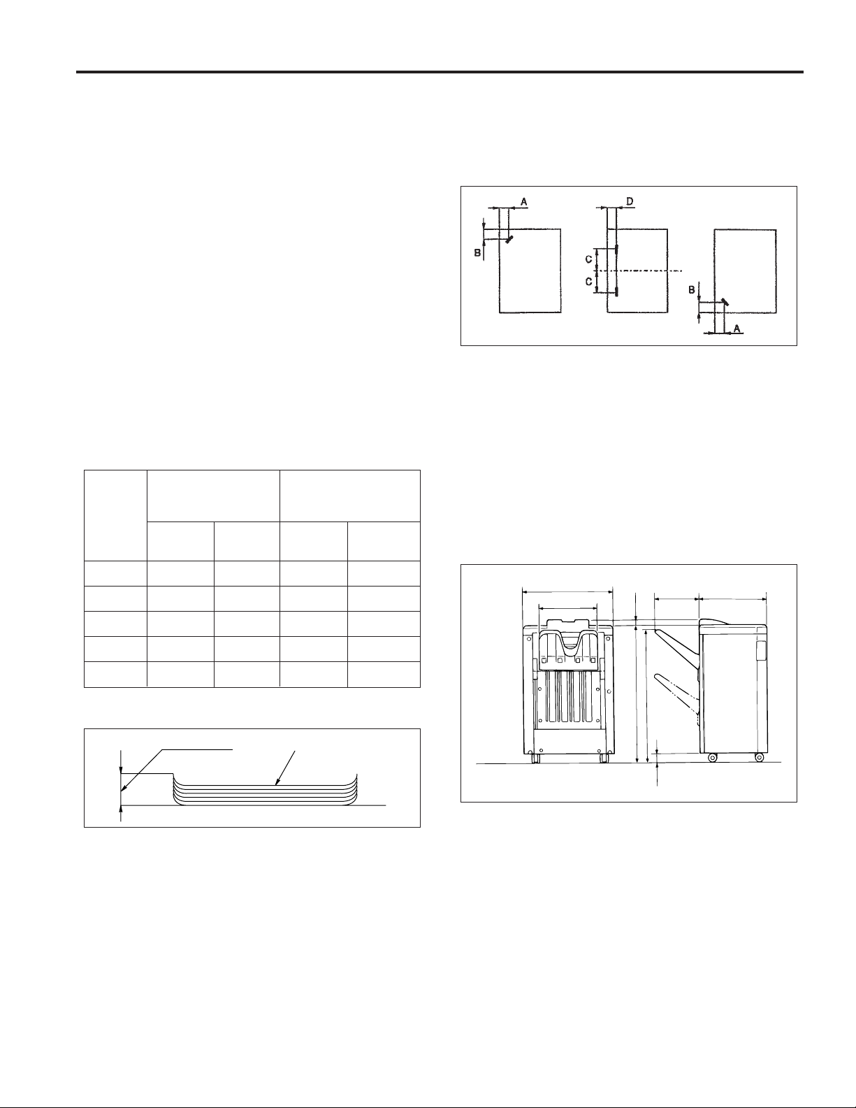
616
367
324 460
915
945
35
63
Type
Type: Offset sorting and stapling equipment
with printer outlet function.
Functions
Types of paper: Same as the main body.
Paper size: 11x17R, 8.5x14R, 8.5x11R, 8.5x11,
8.5x5.5, 8.5x5.5R; however
8.5x5.5R is not possible in staple
mode.
Paper stacking capacity:
Sub-tray exit mode: Maximum 200 sheets
Non-staple/Group/
Off-set mode: Maximum 1,500 sheets (8.5x14R/
11x17R)
Maximum 2,000 sheets
(8.5x5.5R/8.5x5.5/ 8.5x11R/
8.5x11)
Staple mode: Maximum 1,000 sheets
Other than
Number of
original
pages Staple in Staple in Staple in Staple in
11X17R
2 places 1 place 2 places 1 place
11x17R
FS-106
Staple position:
Staple capacity: 5,000 staples/cartridge
A = 8.8 mm (±3 mm adjustment possible)
B = 8.8 mm (±3 mm adjustment possible)
C = 89.1 mm (±3 mm adjustment possible)
D = 8.0 mm (±3 mm adjustment possible)
(Same as FS-103/FS-103A/FS-106)
Machine Data
Power source: 24 V/5 VDC (supplied from the main
body).
Maximum power
consumption: Max. 100 VA (FS-106 only)
Weight: Approximately 110 lb.
External dimensions:
2 to 9 100 stacks 100 stacks 50 stacks 50 stacks
10 to 20 50 stacks 50 stacks 50 stacks 50 stacks
21 to 30 30 stacks 30 stacks 30 stacks 30 stacks
31 to 40 25 stacks 25 stacks 25 stacks 25 stacks
41 to 50 20 stacks 20 stacks 20 stacks 20 stacks
Paper curling: Maximum 10 mm
5 sheets of copy paperAmount of curl
Amount of sort
offsetting: 30 mm (when offsetting/grouping)
Tray: Main tray
Stapler Kit
Number of pages
which may be
stapled: 50 sheets maximum (22 lb. high quality
Sub-tray
paper, 5 mm and below)
Units: mm
Maintenance
Maintenance: Same as the main body
Service life: Same as the main body
Machine Operating Environment
Temperature: 50 to 90°F
Humidity: 10 to 80% RH
These specifications are subject to change without notice.
1
Page 10
FS-106
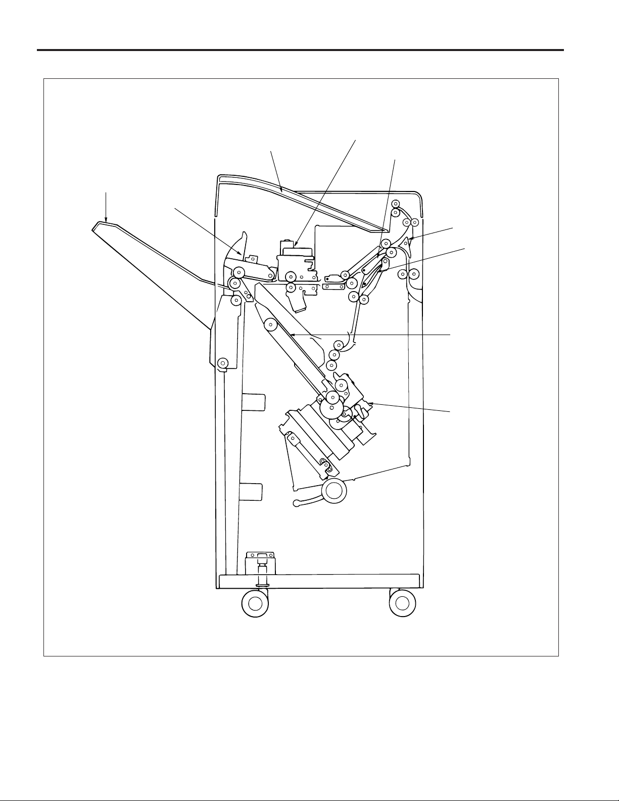
CENTER CROSS SECTION
Subtray
Main tray
Paper exit unit
Shift unit
Gate
Subtray gate
Bypass gate
Stacker unit
Stapler unit
2
Page 11
DRIVE SYSTEM DIAGRAM
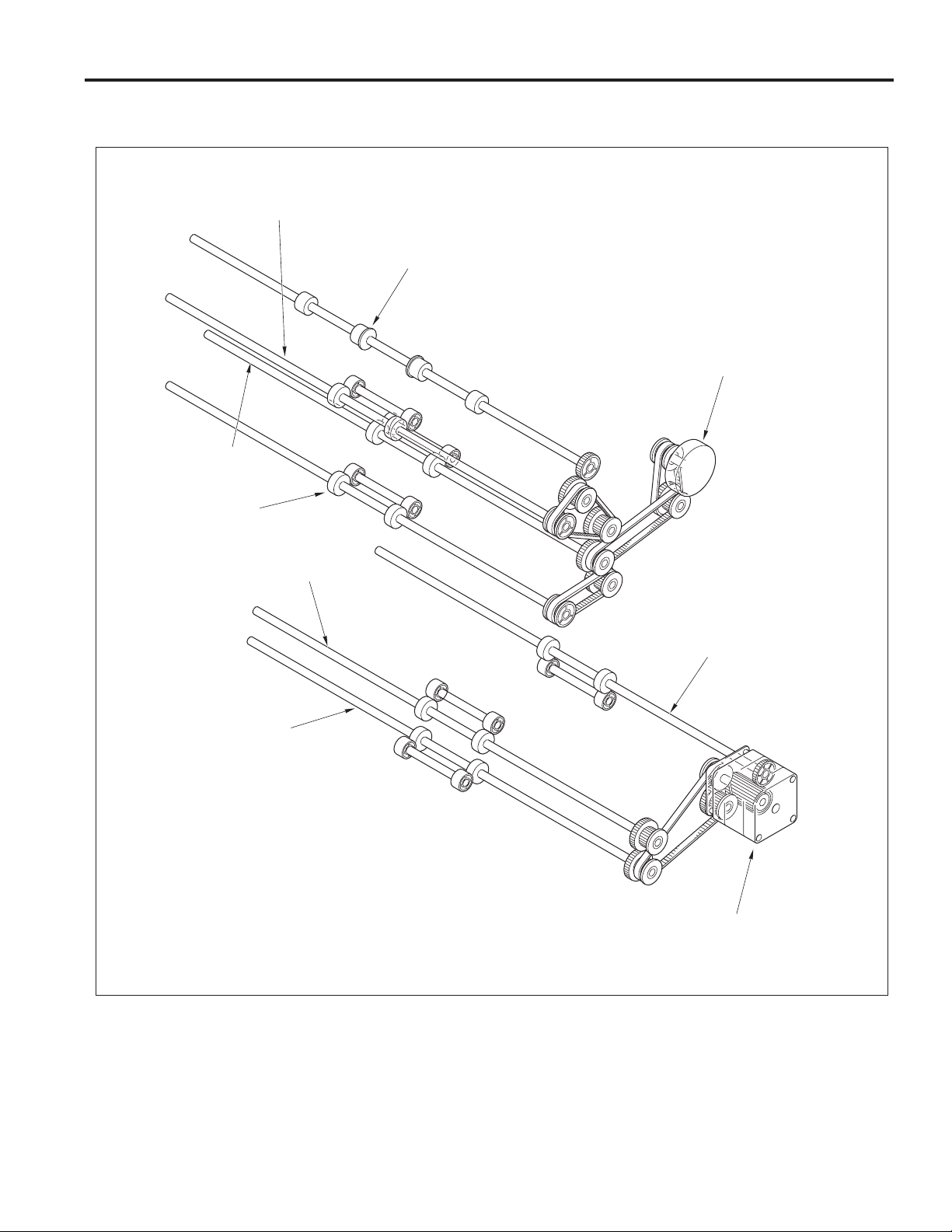
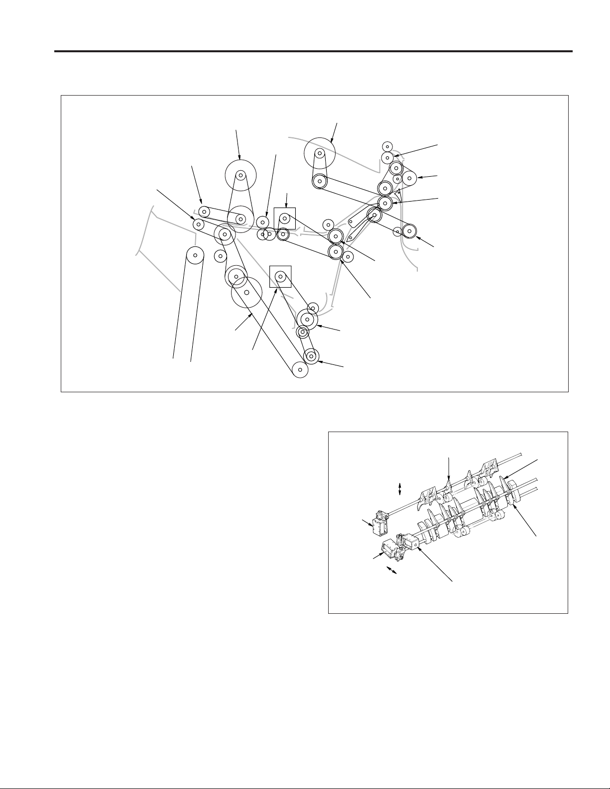
Paper Conveyance Drive
Conveyance roller D
Subtray printer paper exit roller
Conveyance roller B
Conveyance roller A
FS-106
1st conveyance motor (M1)
Conveyance roller C
Intermediate roller
Conveyance slide shaft
2nd conveyance motor (M4)
3
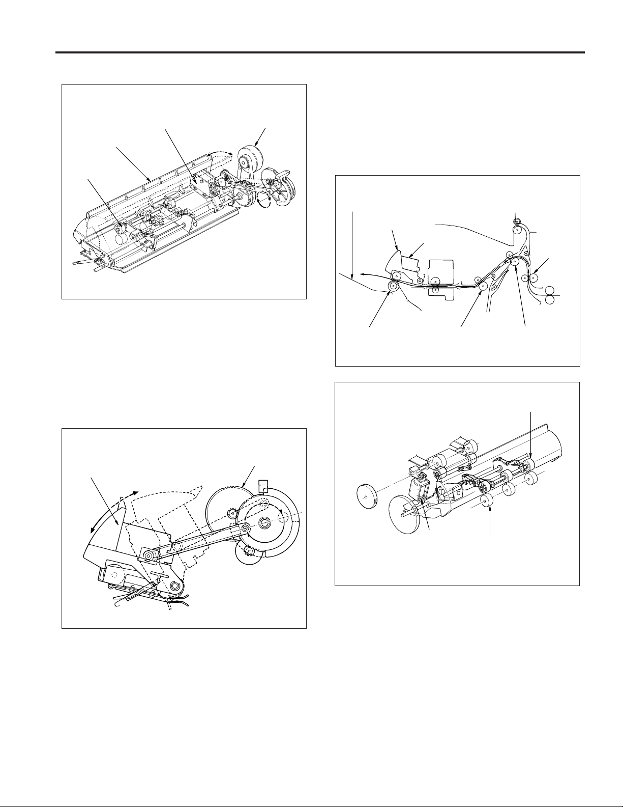
Page 12
FS-106
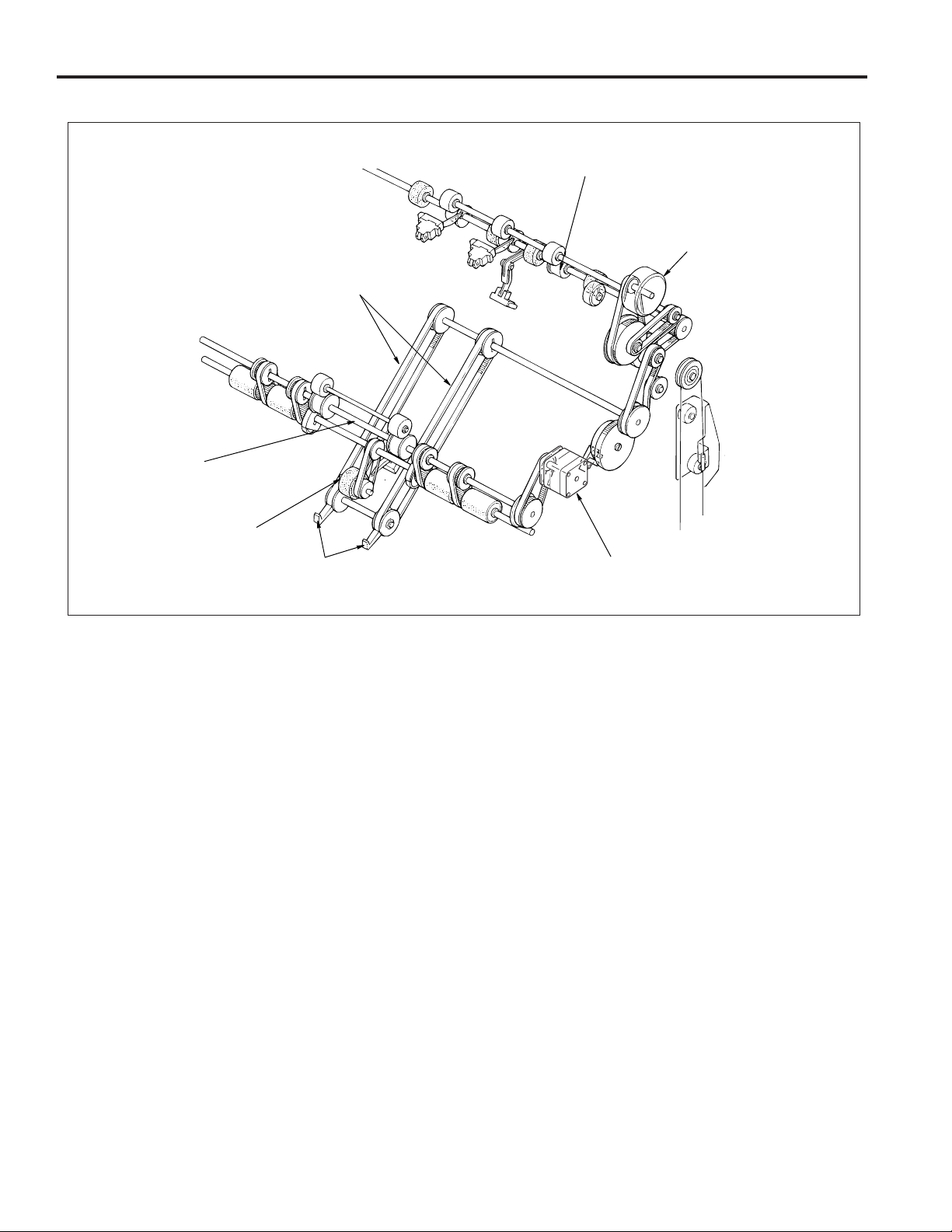
Stacker Drive
Stacker entrance roller
Paper exit roller
Paper exit roller motor (M7)
Paper exit belt
Sponge roller
Paper exit arm
Stacker entrance motor (M14)
4
Page 13
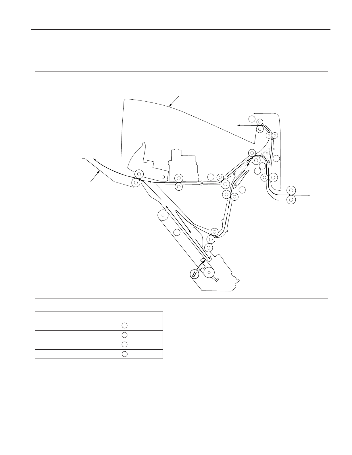
PAPER CONVEYANCE PATH
Paper Conveyance Path
The FNS (finisher) has three paper conveyance paths as shown in the diagram below.
Face up and face down operations are performed in the reversal paper exit section of the main body.
Subtray
2
1
Main tray
3
FS-106
2
3
1
Finishing Paper conveyance paths
Non-Sort mode 1
Sort/Group mode 1
Sub-tray mode 2
Staple mode 3
3
5
Page 14
FS-106
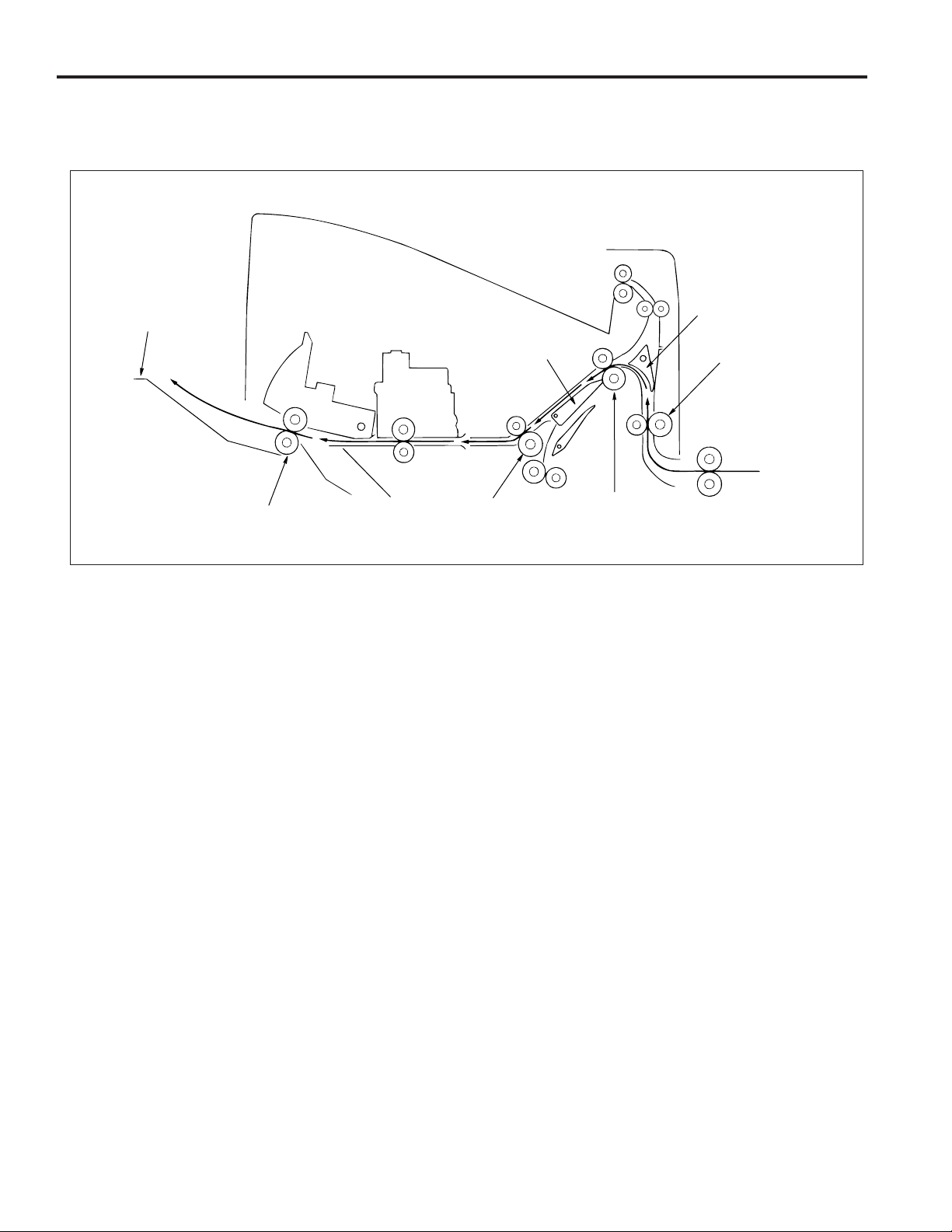
Non-Sort mode
Exit to main tray
A paper exited from the main body is conveyed and exited to the main tray.
Main tray
Paper exit roller
Gate
Shift unit
Conveyance roller C
Subtray gate
Conveyance roller A
Conveyance roller B
6
Page 15
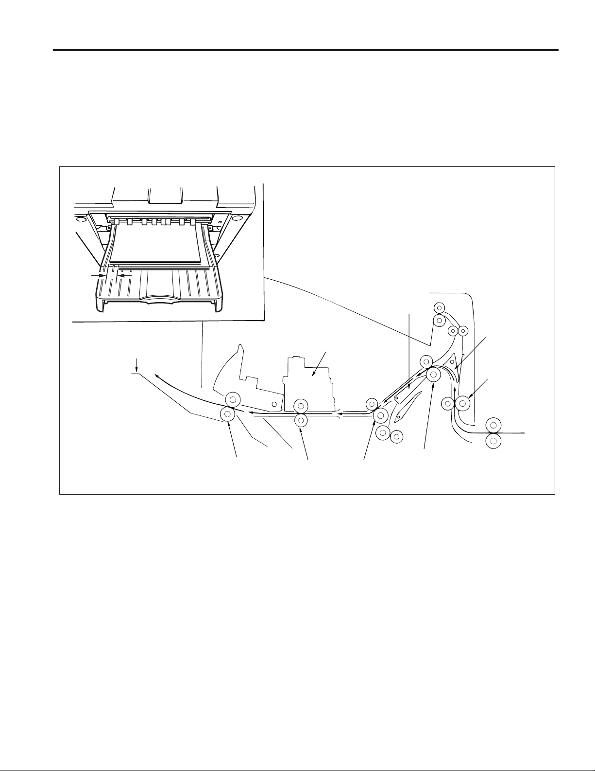
Sort/Group mode
Exit to main tray
Paper exited from the main body is conveyed and exited to the main tray. This mode has an off-set function that allows each page
of the even-numbered sets to be exited with the paper shifted 30mm to the rear.
offset function
(1) The odd-numbered pages are exited to the main tray with the image side face down.
(2) The even-numbered pages are shifted 30mm to the rear by the conveyance slide shaft of the shift unit and then
exited to the main tray.
30mm
Gate
FS-106
Main tray
Paper exit roller
Shift unit
Conveyance
slide shaft
Subtray gate
Conveyance roller A
Conveyance roller B
Conveyance roller C
7
Page 16
FS-106
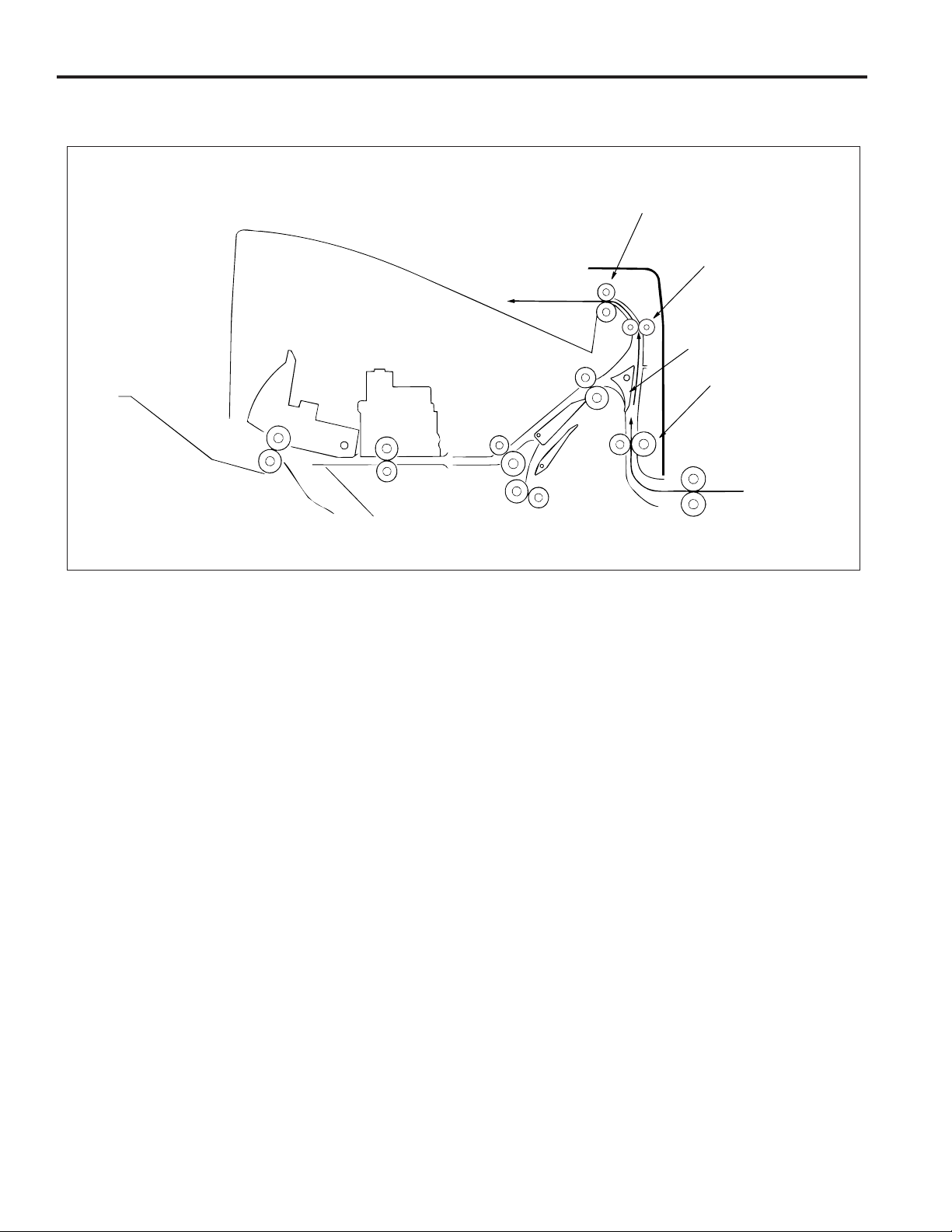
Subtray mode
The subtray gate opens. Paper exited from the main body is conveyed and exited to the subtray.
Paper exit roller
Subtray
Conveyance roller D
Subtray gate
Conveyance roller A
8
Page 17
FS-106
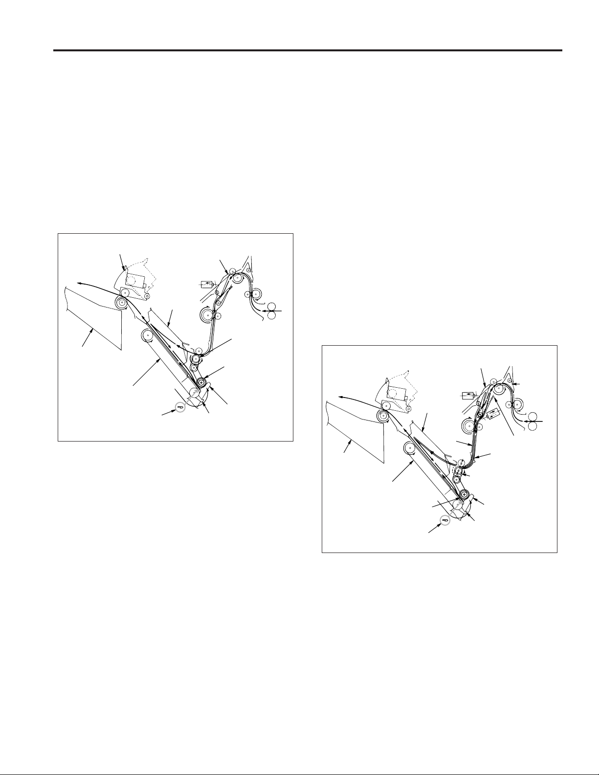
Staple mode
(1) The gate switches to the staple mode.
(2) For 8.5x11R paper and above, the paper exit opening
opens.
(3) The first stack of paper is conveyed and stacked.
(a) The sponge roller of the stacker section sends the
paper to the stopper and the paper is lined up in
the lengthwise direction.
(b) The alignment plate unit lines up paper in the width-
wise direction.
(c) Paper is stapled.
(d) The first stack is conveyed by the paper exit arm
and exited to the main tray.
Paper exit opening
1st stack
Alignment
plate unit
Main tray
Stacker
Stapler
Gate
Stacker
entrance roller
Sponge roller
Stopper
Paper
exit arm
(4) The second and subsequent stacks of paper are con-
veyed and stacked.
(a) The first page stops in the stacker entrance with
the bypass gate opened. The stacker entrance
roller stops to wait for the previous stack to be
exited.
(b) The bypass gate is closed and the second page
is stacked on top of the first.
(c) Once the previous stack has exited, the stack en-
trance roller rotates and the first and second pages
are simultaneously sent to the stacker.
• The above steps (a) to (c) are for paper to a maximum of 8.5x11 size.
(d) The sponge roller of the stacker section sends the
paper to the stopper and the paper is lined up in
the lengthwise direction.
(e) The alignment plate unit lines up paper in the width-
wise direction.
(f) When all paper is conveyed to the stacker, the pa-
per is stapled.
(g) The second and subsequent sets are conveyed
by the paper exit arm and the paper is exited to
the main tray.
2nd and
subsequent
stacks
Alignment
plate unit
2nd
page
Main tray
Gate
Subtray
gate
Bypass gate
1st page
Stacker entrance roller
Stacker
Sponge roller
Stapler
Stopper
Paper exit arm
9
Page 18
FS-106
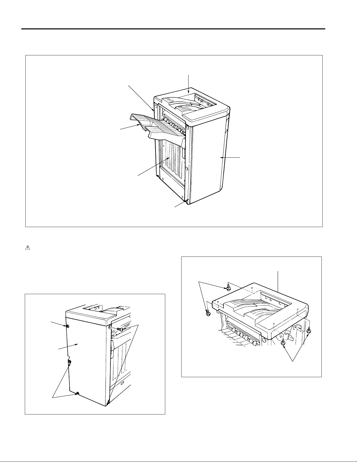
EXTERNAL SECTION
Composition
Rear cover
Main tray
Paper exit
stopper plate
Top cover
Front cover
Disassembly and Assembly
CAUTION
Be sure that the power cord has been unplugged from
the outlet.
1. Removing/installing the rear and top covers
a. Procedure
(1) Remove the 5 screws and remove the rear cover.
Screw
Rear cover
Screws
Front side cover
(2) Open the front cover.
(3) Remove the 4 screws and remove the top cover.
Top cover
Screws
Screws
Screws
(4) Reinstall the rear and top covers in the opposite se-
quence to removal.
10
Page 19
FS-106
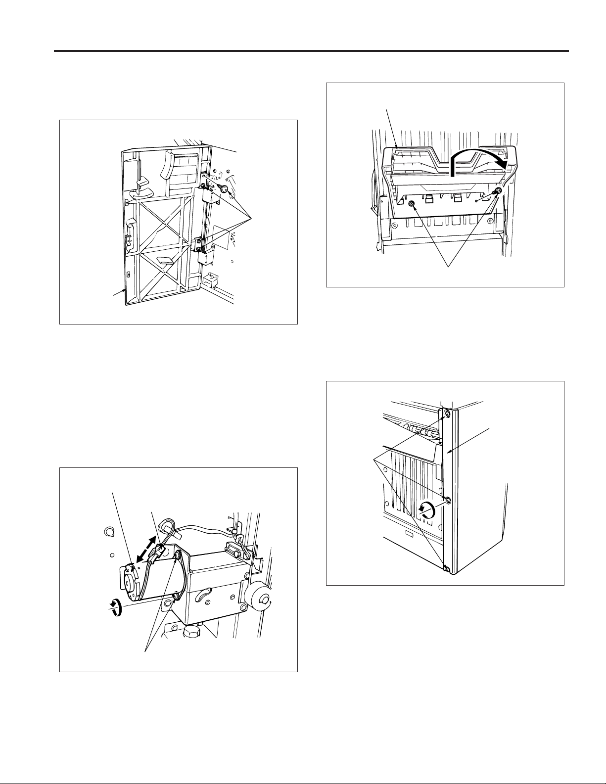
2. Removing and installing the front cover
a. Procedure
(1) Open the front cover.
(2) Remove the 4 screws and remove the front cover.
Screws
Front cover
(3) Reinstall the front cover in the opposite sequence to
removal.
3. Removing and installing the main tray
a. Procedure
(1) Remove the rear cover.
(2) Remove the connector and the 2 screws, then remove
the tray up-down motor (M3).
CAUTION: Take out the tray up-down motor while sup-
porting the main tray with your hand.
(3) Remove the 2 screws, lift up and remove the main tray.
Main tray
Screws
(4) Reinstall the shift tray in the opposite sequence to re-
moval.
4. Removing and installing the front side cover
a. Procedure
(1) Remove the 3 screws and remove the front side cover.
Front side cover
Screws
Tray up-down motor (M3)
Connector
Screws
(2) Reinstall the front side cover in the opposite sequence
to removal.
11
Page 20
FS-106
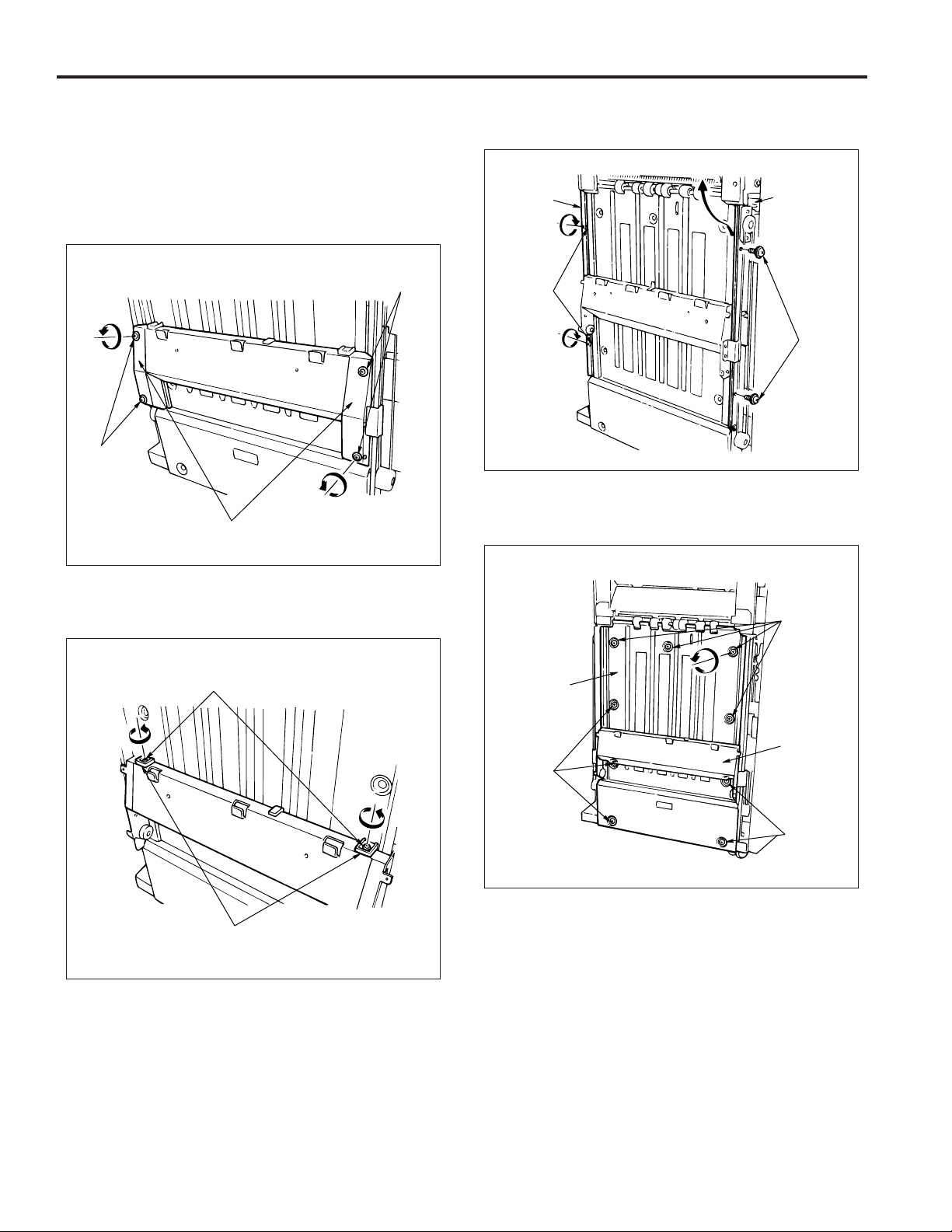
5. Removing and installing the paper exit stopper
plate
a. Procedure
(1) Remove the rear cover, main tray and the front side
cover.
(2) Remove the 4 screws and remove the left and right
up-down covers.
Screws
Screws
Up-down cover
(4) Remove the 2 screws and take out the up-down sup-
port plate (front and rear).
Up-down
support
plate (rear)
Screws
Up-down
support
plate (front)
Screws
(5) Remove the 9 screws, lift the up-down stay and take
out the paper exit stopper plate to the lower side.
(3) Remove the 2 screws and remove the 2 slide stop-
pers.
Screws
Slide stoppers
Screws
Paper exit
stopper plate
Up-down
stay
Screws
Screws
(6) Reinstall the paper exit stopper plate in the opposite
sequence to removal.
12
Page 21
CONVEYANCE SECTION
Composition
FS-106
Paper exit roller
(sponge roller)
Paper exit roller motor (M7)
Nip paper exit roller
Paper exit belt
Stacker entrance
Conveyance
motor (M14)
slide shaft
2nd
conveyance
motor (M4)
1st conveyance motor (M1)
Subtray paper exit roller
Conveyance roller D
Conveyance roller B
Conveyance roller A
Conveyance
roller C
Intermediate roller
Stacker entrance roller
Sponge roller
Mechanism
1. Paper conveyance
Paper conveyance is performed by the conveyance rollers A,
B, C and D, the intermediate roller, conveyance slide shaft and
subtray paper exit roller. These components are driven by
the 1st conveyance motor (M1) and the 2nd conveyance motor
(M4) through the timing belt.
Stacking to the paper stacker is performed by the stacker
entrance roller and sponge roller. These are driven by the
stacker entrance motor (M14) via the timing belt.
Paper exiting is performed by the stacker paper exit belt arm
and the paper exit rollers. These are driven by the paper exit
motor (M7) via the timing belt.
2. Paper path switching
Subtray gate
Subtray
paper
exit
solenoid
(SD2)
Bypass
solenoid
(SD5)
OFF
ON
ON
OFF
Gate solenoid
(SD1)
The paper route switches using the gate, subtray gate and
bypass gate. Each gate operates with the ON/OFF switching
of the gate solenoid (SD1), subtray paper exit solenoid (SD2)
and by-pass solenoid (SD5).
Gate
Bypass
gate
13
Page 22
FS-106
3. Shift unit sort shift operation
(1) The paper in the shift unit is fed in the exit direction by
the slide shaft.
(2) When the roller shift motor (M2) rotates, the link mecha-
nism shifts the paper along with the slide shaft, 30mm
towards the direction of the back side.
Shift unit
Exit direction
Slide shaft
Slide shaft
Link mechanism
Link mechanism
30mm towards the direction
of the back side
Roller shift
motor (M2)
Roller shift motor (M2)
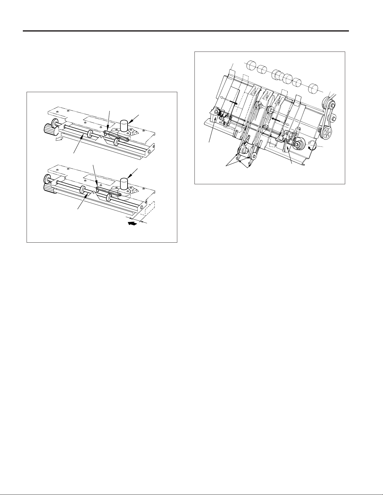
4. Stacker unit
Alignment
plate
Paper exit belt
Paper exit arm
Alignment plate
Alignment
plate
motor
(M5)
Paper alignment
Paper in the stacker is lined up by the forward and reverse
movement of the alignment plates. The forward/reverse motion
of the alignment plates is performed by the alignment plate
motor (M5).
Paper exiting
The paper exit arm sends the stapled paper out to the paper
exit opening.
The paper exit belt is rotated by the paper exit roller motor
(M7).
14
Page 23
FS-106
5. Paper exit opening unit
Paper exit opening
Paper exit
opening
Nip roller
solenoid (SD4)
Close Open
(1) Stapling mode for paper sized 8.5x11R and above
The paper exit opening is opened from the time copying commences to the time stapling is complete.
(2) Paper exit of the staple mode
When the stapling has finished, the paper exit opening is closed, the paper gripped and exited to the main
tray. The opening and closing of the paper exit opening is performed by the paper exit opening motor (M8).
Paper exit
opening motor
(M8)
(3) Pressure of the paper exit roller
The paper exit roller rotation is slower than the conveyance rollers A, B and C. Therefore pressure is released at times other than when paper is exiting.
When the paper reaches the paper exit opening the
paper exit roller applies pressure and paper is exited
to the main tray . The pressing and releasing of paper is
performed by the paper exit opening solenoid (SD4).
Main tray
Paper exit roller
Paper exit
opening
Paper exit
opening solenoid
(SD4)
Conveyance
roller C
Conveyance
roller B
Nip roller
Conveyance
roller A
Paper exit
opening
Close
Open
Paper exit
opening motor (M8)
Paper exit
opening
solenoid
(SD4)
Paper exit
roller
15
Page 24
FS-106
6. Intermediate conveyance roller
In this machine, in order to be compatible with thick paper,
it has its pressure of the intermediate conveyance roller
set at a slightly higher level.
While in conveyance collectively of the 1st and 2nd copies
of the 2nd set and later to the stacker in staple copy mode
for small-sized paper, the decompression solenoid (SD3)
is operated to lower the pressure of the intermediate conveyance roller.
This is to prevent dirt from the roller from sticking to the
paper and wrinkles from taking place on paper in conveyance.
2nd copy
1st copy
Intermediate roller
Disassembly and Assembly
CAUTION
Be sure to remove the power cord from the power
outlet.
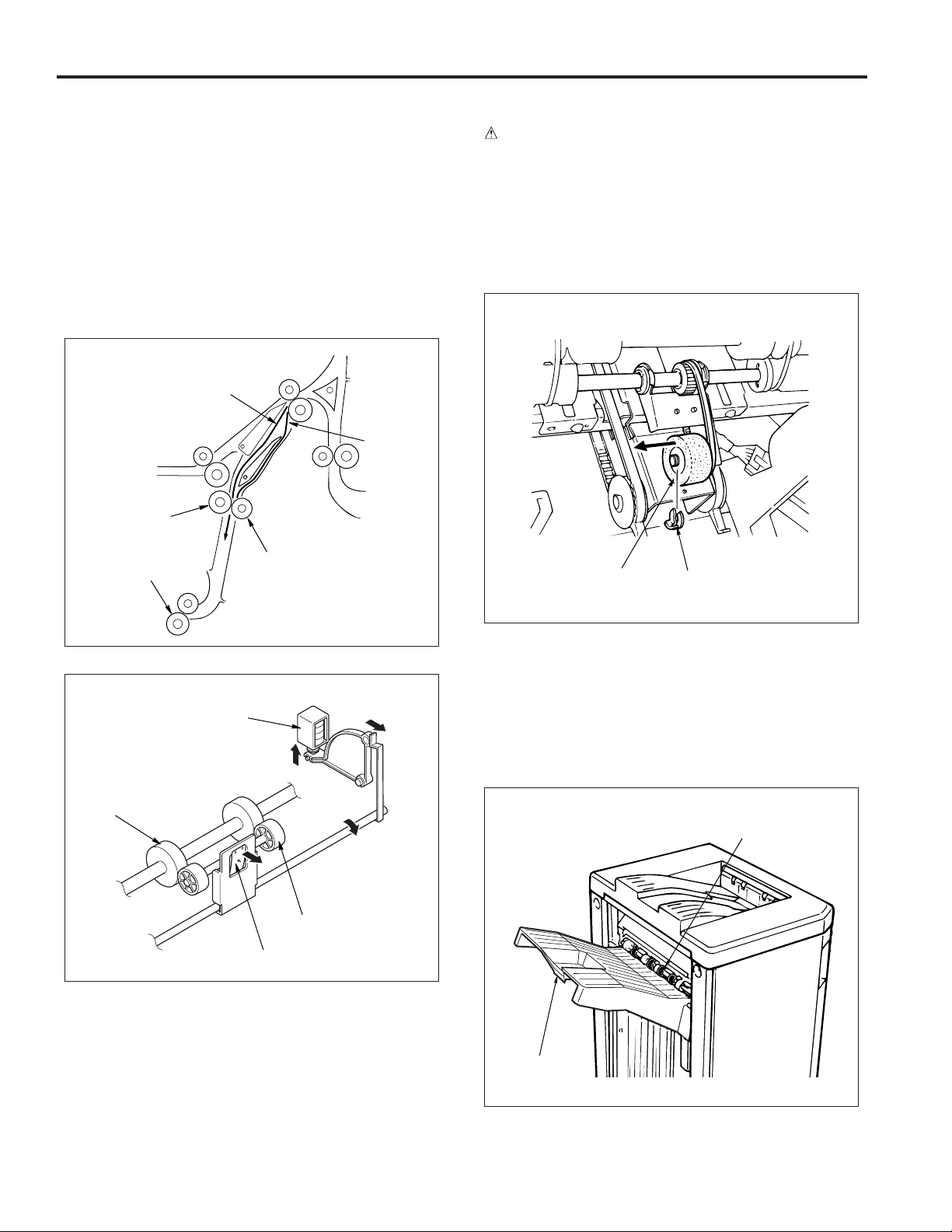
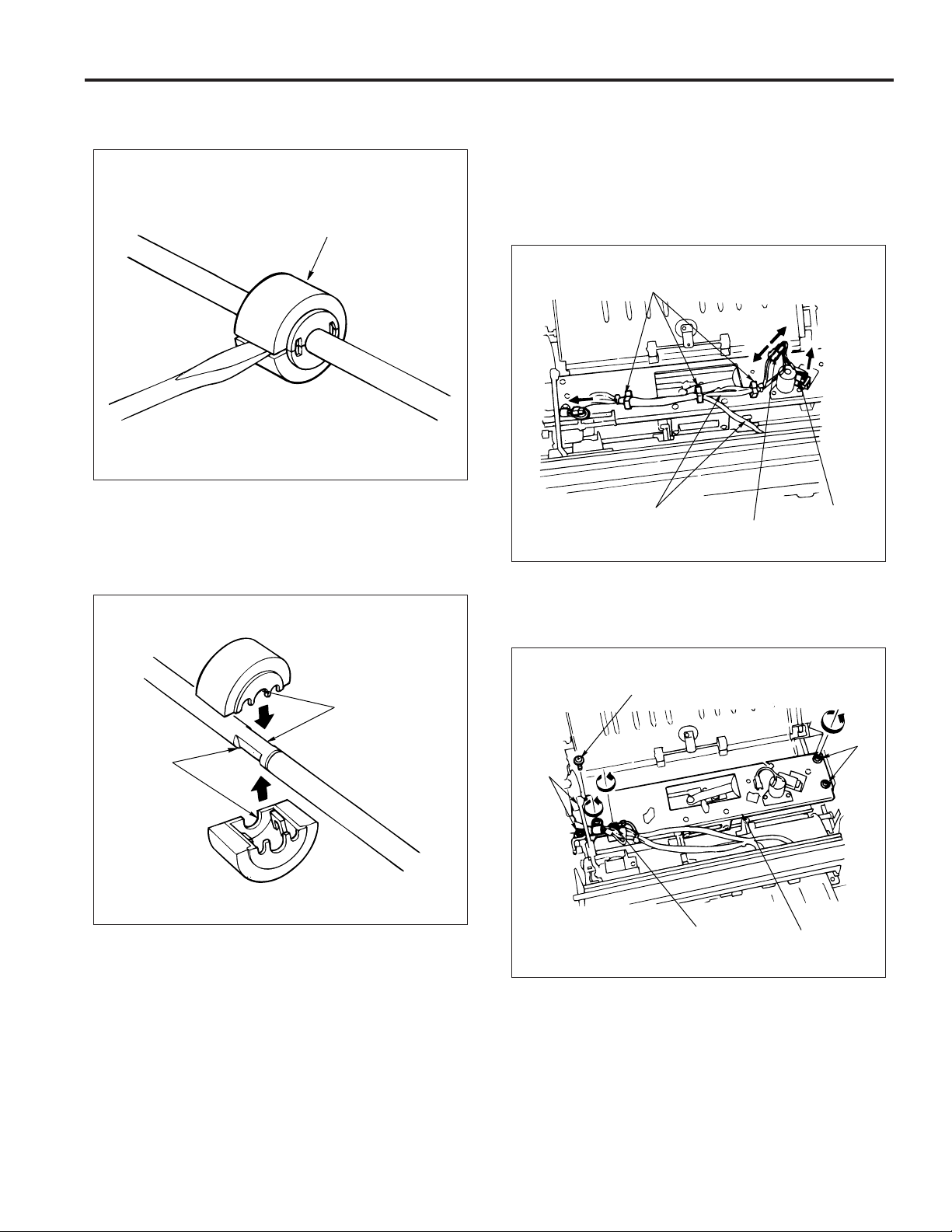
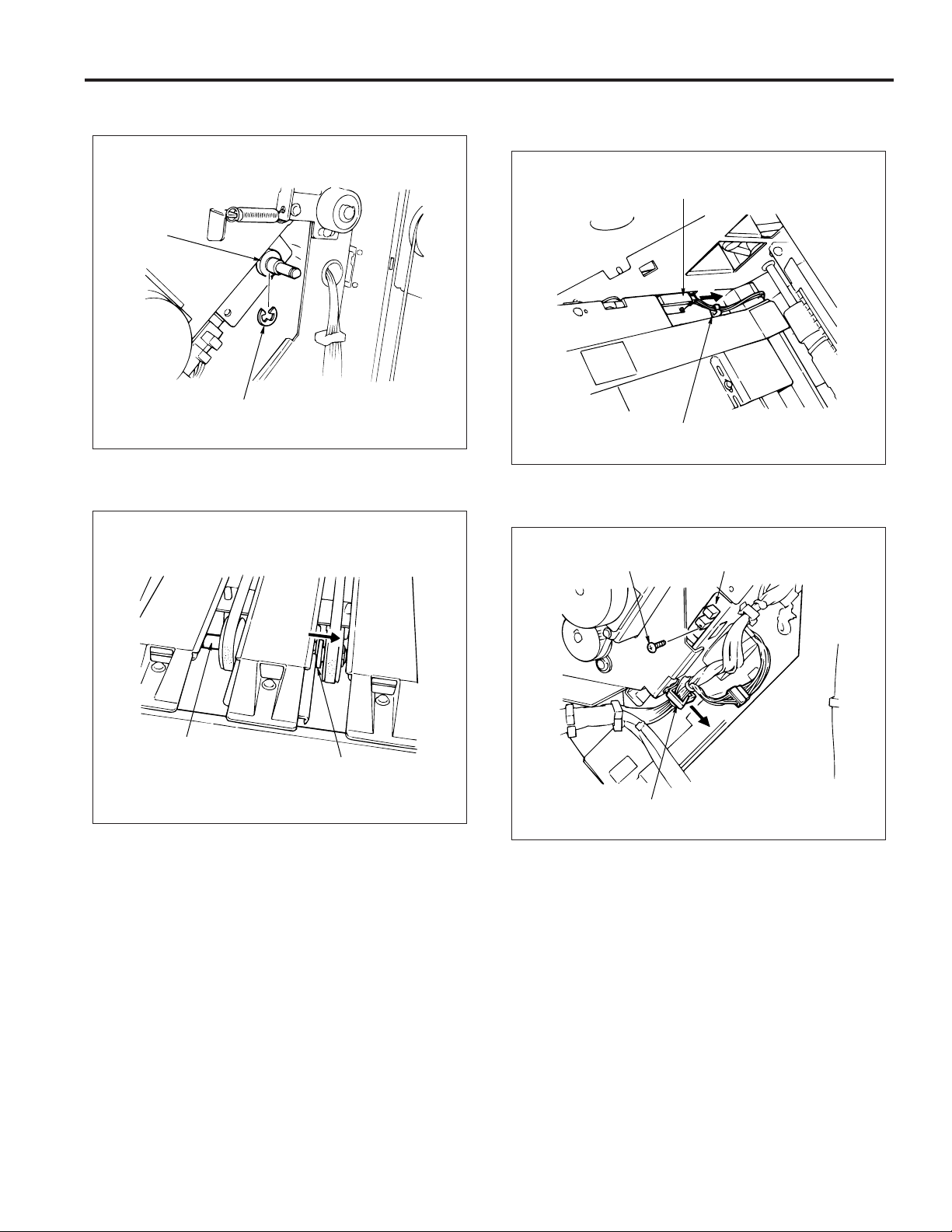
1. Exchanging the stacker unit section sponge
roller
a. Procedure
(1) Open the front cover, remove the fixing ring of the
stacker unit section and then remove the sponge roller .
Stacker entrance roller
Decompression
solenoid (SD3)
Intermediate roller
Backup roller
Backup roller
Tension spring
Sponge roller
Fixing ring
(2) Reinstall the sponge roller in the opposite sequence
to removal.
2. Exchanging the paper exit roller (sponge roller)
a. Procedure
(1) Move the main tray down by using the 47 mode func-
tion (75-06 code).
Sponge rollers
16
Main tray
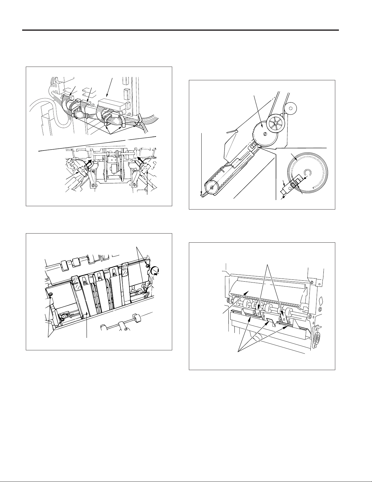
Page 25
FS-106
(2) Insert a screwdriver into the slot of the sponge roller,
then pry the roller open.
Sponge roller
(3) Align the grooves of the new sponge rollers with the
shaft.
(4) Press the sponge rollers until a click sounds, so that
they are properly installed.
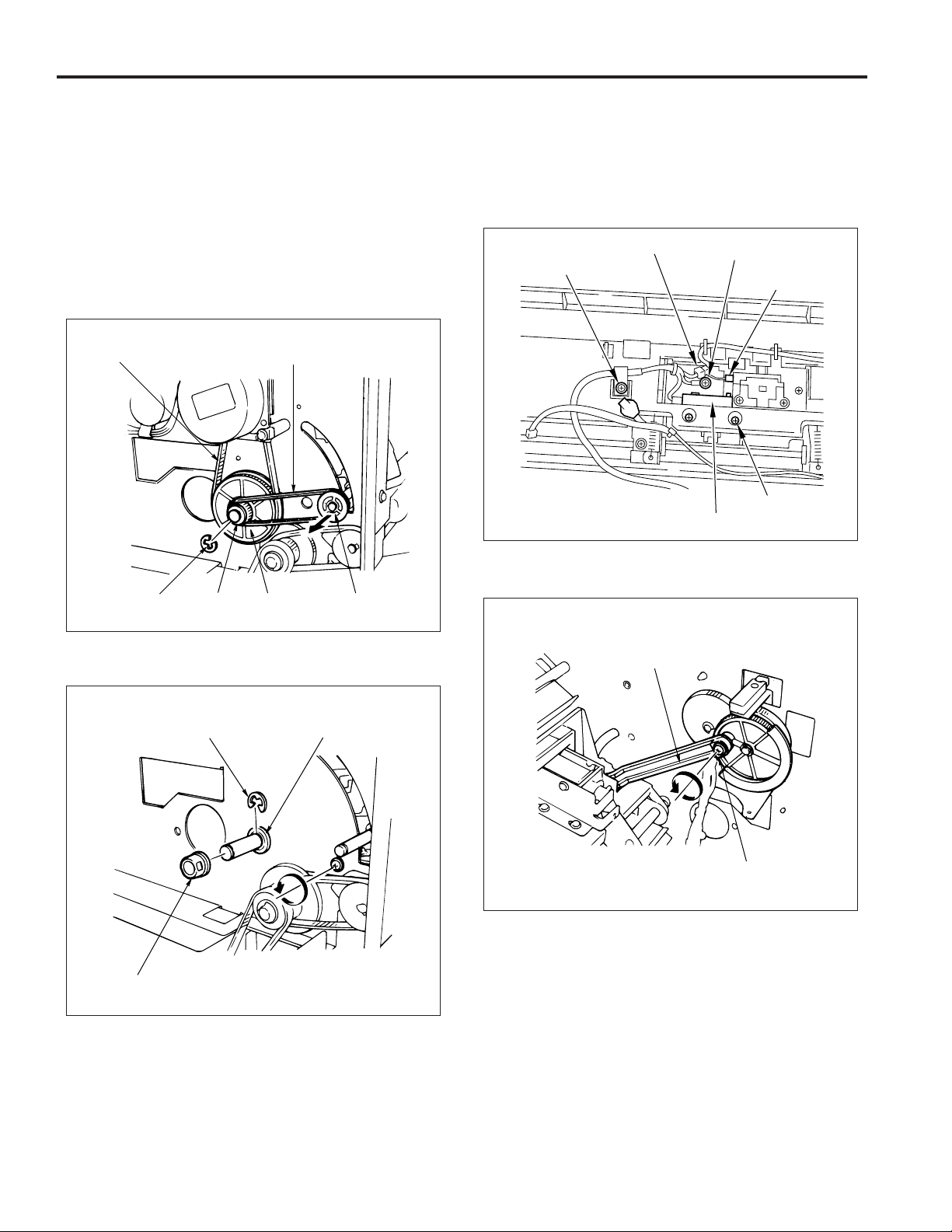
3. Removing and reinstalling the shift unit
a. Procedure
(1) Remove the following parts:
• rear cover
• top cover
(2) Remove the connector of M2 and PS18.
(3) Remove the wiring from the three clamp positions.
Clamps
Wiring
M2 connector
(4) Remove the ground wire fixing screw.
(5) Remove the clamp screw.
(6) Remove the 4 screws, then remove the shift unit.
PS18
connector
Align
Align
Clamp screw
Screws
Ground wire
fixing screw
Shift unit
(7) Reinstall the shift unit in the opposite sequence to re-
moval.
Screws
17
Page 26
FS-106
4. Removing and installing the paper exit
opening unit
a. Procedure
(1) Remove the following parts:
• rear cover
• top cover
• front side cover
• shift unit
(2) Remove the pulley and belt.
(3) Remove the e-ring and then remove the collar, gear
and drive belt.
Drive belt
Belt
(5) Remove the clamp screw and the ground wire screw.
(6) Remove the connector of SD4 and PS6.
(7) Remove a set screw and withdraw the PS23 from the
unit, then remove the connector.
Note: When withdrawing the PS23, ensure that needless
force is not applied to the lever below the PS23.
SD4 connector
Clamp screw
Ground wire screw
PS6 connector
Screw for PS23
SD23
E-ring
Collar
Gear
Pulley
(4) Remove the collar, e-ring and shaft holder.
E-ring
Collar
Shaft holder
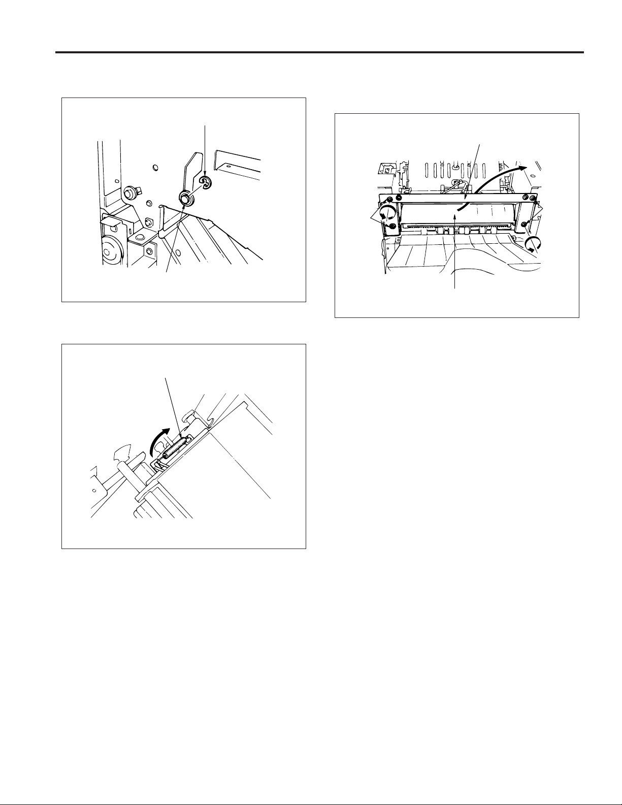
(8) Remove the paper exit opening open-shut link screw.
Paper exit opening
open-shut link
Screw
18
Page 27
FS-106
(9) Open the front cover and remove the front side e-ring
and shaft holder.
E-ring
Shaft holder
(10)Remove the spring.
(11)Remove the 4 screws and then remove the paper exit
opening cover.
(12)Take the paper exit opening unit out to the top.
Paper exit
opening cover
Screws
Screws
Paper exit
opening unit
(13) Reinstall the paper exit opening unit in the opposite
sequence to removal.
Spring
19
Page 28
FS-106
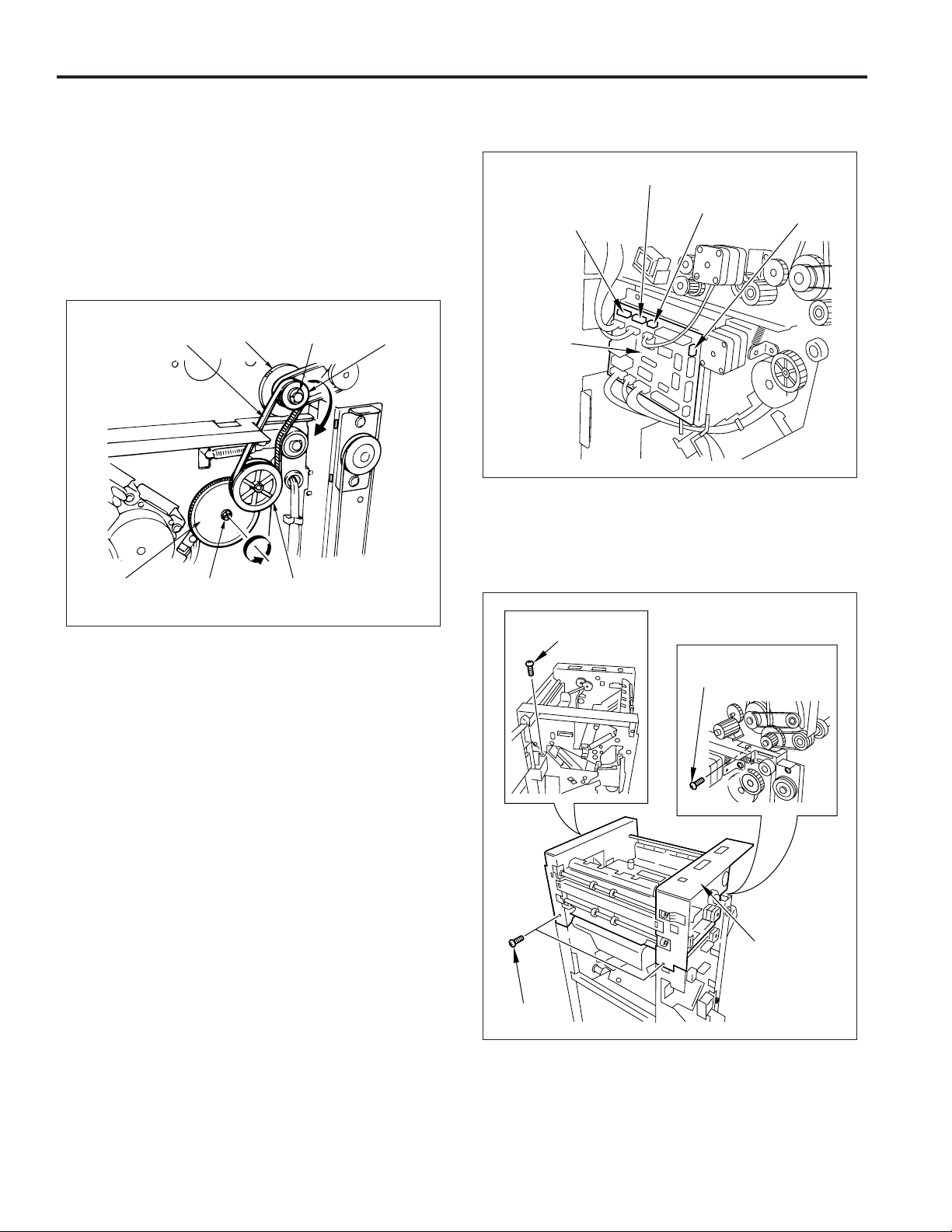
5. Removing/installing the stacker unit
a. Procedure
(1) Remove the following parts:
• rear cover
• top cover
• front side cover
(2) Take out the e-ring and flange, then remove the belt
and the two pulleys.
(3) Remove the shaft with a screwdriver and remove the
belt detection gear.
Belt
Belt detection
gear
Pulley E-ring Flange
Shaft
Pulley
(4) Remove the four connectors (CN1, CN5, CN11, CN12)
on the FNS control board.
CN5
CN11
CN1
FNS control
board
CN12
(5) Remove the four set screws, then remove the convey-
ance unit.
Note: When placing the conveyance unit on the floor, etc.,
ensure that it is placed upside down.
Set screws
Set screw
Set screw
Conveyance unit
20
Page 29
FS-106
(6) Remove the e-ring and then shift the shaft holder.
Shaft
holder
E-ring
(7) Shift the shaft holder and then remove the shaft.
(8) Remove the connector of PS9 and then remove the
wiring from the clamp.
PS9 connector
Clamp
(9) Remove the screw and then remove PS9.
Shaft
Shaft holder
Screw
Clamp
PS9
21
Page 30
FS-106
(10)Remove CN6 and CN3 on the FNS control board and
the stapler F and R connectors. Then remove the
wiring from the clamp.
FIN control board
CN6
CN3
Clamps
Stapler F
connector
Stapler R connector
(11) Remove the 4 screws and then remove the stacker
unit.
Screws
CAUTION:
1. When the stacker paper exit arm is in the position as
that of the diagram, engage the gear so that the notch
of the detection gear actuator meets with the edge of
PS9 as per the diagram below.
Belt detection gear
Stacker paper
exit arm
Actuator
PS9
Actuator notch
2. When reinstalling the stacker unit, be careful not to
damage the conveyance guide sheets on the stacker
unit guide plate.
Screws
Stacker unit
(12)Reinstall the stacker unit in the opposite sequence to
removal.
Conveyance guide sheet
Conveyance
unit
Stacker unit guide plate
22
Page 31

FS-106
M1 (1st conveyance) Control
P.GND
101-4
P.GND
101-5
S.GND
101-3
5V
101-2
TXD
114-1
DTR
114-2
RTS
114-6
RXD
114-3
DSR
114-7
CTS
114-5
24V
101-1
MAIN BODY
MS1
The 1st conveyance control during main tray paper exit and the
paper exit control during subtray paper exit are done by
transmitting the rotation of M1 (1st conveyance) to conveyance
rollers (A), (B), (D), and to the subtray paper exit roller.
FNS CB (FNS control board) controls M1.
1. Operation
a. Interlock
Paper 1st conveyance control commences with the ON
signal from the main body start button. However, if MS1
(interlock) is OFF, error data will be output to the main body
CB and control will not commence.
9-3
9-4
9-5
9-7
10-1
10-2
10-3
10-4
10-5
10-6
9-1
RXD
CTS
DSR
TXD
RTS
DTR
24V-IN
FNS CB
VCC
M1 BLK
M1 CONT
M1 CLK
M1DIR
24V
24V
24V
24V GND
24V GND
VCC
PS4 IN
GND
GND
PS1 IN
5-A1
5-B10
5-B9
5-B8
5-B11
1-A1
1-A2
1-A3
1-A5
1-A6
5-A3
5-A8
5-B4
5V
5-A5
5-B6
5-A7
M1
PS4
PS1
b. M1 (1st conveyance) Control
(1) Main tray paper exit operation
M1 (1st conveyance) turns ON by the ON signal of the
start button and goes OFF after the specified time
when PS4 (FIN entrance path) detects the trailing edge
of the final copy.
(2) Sub-tray paper exit operation
M1 turns ON by the ON signal of the start button, and
rotates at high speed. When PS4 (FIN entrance path)
detects the trailing edge of the paper, rotation switches
to low speed after the specified time. Then, rotation
once again returns to high speed to be ready for
conveyance of the next copy. On detection of the
trailing edge of the final copy by PS4, it turns OFF in the
specified time.
M1 (1st convenyance)
PS1 (subtray upper limit)
Subtray
paper exit roller
Conveyance
roller D
Conveyance
roller B
PS4
(FIN entrance path)
Conveyance roller A
c. Subtray Upper Limit Detection Control
PS1 (subtray upper limit) is fitted in the subtray, and when
PS1 turns ON by detecting paper during subtray paper
exit, the main body and the FNS stop after ejecting the
paper being copied at that time.
2. Signals
a. Input signals
(1) TXD (main body CB −> FNS CB)
This is a serial data line to transmit the operational
state of the main body CB to the FNS CB.
(2) DTR (main body CB −> FNS CB)
Transmission acknowledgement signal from the main
body to FNS.
(3) RTS (main body CB −> FNS CB)
Request-to-send signal from the main body to FNS.
(4) 24 V IN (MS1 −> FNS CB)
When MS1 (interlock) goes ON, +24 V is output. This
power supply is supplied to each electrical load of FNS.
23
Page 32

FS-106
(5) PS1 IN (PS1 −> FNS CB)
When the subtray is full, PS1 (subtray upper limit)
goes ON and inputs [L].
(6) PS4 IN (PS4 −> FNS CB)
When paper passes through the FNS entrance, this
signal turns ON and [L] is input.
b. Output signals
(1) TXD (FNS CB −> main body CB)
This is a serial data line to transmit the operational
state of the main body CB to the FNS CB.
(2) RTS (FNS CB −> main body CB)
Transmission acknowledgement signal from the main
body to FNS.
(3) DTR (FNS CB −> main body CB)
Request-to-send signal from the main body to FNS.
(4) M1 CONT (FNS CB −> M1)
Operational signal used by M1 (1st conveyance). M1
turns ON at the same time as the finisher operation
start signal.
[H]: OFF
[L]: ON
(5) M1 BLK (FNS CB −> M1)
M1 (1st conveyance) brake signal.
[H]: OFF
[L]: ON
(6) M1 CLK (FNS CB −> M1)
M1 (1st conveyance) speed adjustment clock.
(7) M1 DIR (FNS CB −> M1)
M1 (1st conveyance) rotation direction signal.
[H]: Forward rotation (CW)
[L]: Reverse rotation (CCW)
M4 (2nd conveyance) Control
P.GND
101-4
P.GND
101-5
S.GND
101-3
5V
101-2
TXD
114-1
DTR
114-2
RTS
114-6
RXD
114-3
DSR
114-7
CTS
114-5
24V
101-1
MAIN BODY
MS1
The 2nd conveyance control during main tray paper exit is done
by transmitting the rotation of M4 (2nd conveyance) to the
intermediate roller, conveyance roller (C), and the conveyance
slide shaft.
FNS CB (FNS control board) controls M4 only when the main
tray paper exit is operated in the sort/group/non-sort/staple
mode.
1. Operation
Nip paper exit roller
9-3
9-4
9-5
9-7
10-1
10-2
10-3
10-4
10-5
10-6
9-1
RXD
CTS
DSR
TXD
RTS
DTR
24V-IN
M4 DRV A
M4 DRV A
M4 DRV B
M4 DRV B
PS4-IN
SD3 DRV
PS6-IN
FNS CB
24V
24V
VCC
GND
24V
GND
Conveyance slide roller
M4 (2nd conveyance)
12-1
12-6
12-2
12-3
12-4
12-5
5-A3
5-A8
5-B4
1-A9
1-A8
5V
5-A6
5-B7
5-A10
M4
PS4
SD3
PS6
Stacker entrance roller
a. During Sort/Group/Non-Sort Mode
M4 (2nd conveyance) turns ON by the ON signal of the start
button, and rotates at high speed. When PS4 (FIN entrance path) detects the trailing edge of the paper fed from
the main body, rotation switches to low speed after the
specified time.
Then, rotation once again returns to high speed to be ready
for conveyance of the next copy. On detection of the trailing
edge of the final copy by PS4, it turns OFF in the specified
time.
24
Conveyance
roller (C)
Intermediate roller
PS4 (FIN entrance
path)
Page 33

FS-106
b. During Staple Mode
(1) ON timing of M4 (2nd conveyance)
M4 (2nd conveyance) goes ON by the ON signal of
the start button, and rotates at high speed. When PS4
(FIN entrance path) detects the trailing edge of the
paper fed from the main body, rotation switches to low
speed after the specified time.
Then, rotation once again returns to high speed to be
ready for conveyance of the next copy.
(2) Paper conveyance of the 1st copy of the 2nd and later
sets
When PS4 (FIN entrance path) detects the trailing edge
of the 1st copy fed from the main body, it goes OFF
after the specified time, and enters a standby mode to
convey the 2nd copy .
As a result, the 1st copy is conveyed to the stacker
entrance.
(3) Paper conveyance of the 2nd copy of the 2nd and later
sets
When PS4 detects the trailing edge of the 2nd copy,
M4 starts to rotate at high speed after the specified
time. Then, in the specified time from detection of the
trailing edge of the 2nd copy by PS4, M4 is switched
over into low speed rotation.
Further, in the specified time, it once again returns to
high speed rotation which is the standby state for conveyance of the 3rd copy and later.
For the 3rd copy and later, rotation is switched over
into low speed in the specified time after the trailing
edge of the copy is detected by PS4, and is returned
to high speed in the specified time.
(4) OFF timing of M4 (2nd conveyance)
M4 turns OFF in the specified time after PS6 (paper
exit 1) detects the final set stapled.
c. Pressing Release Operation of Intermediate
Roller
The intermediate roller, when conveying the 1st and 2nd
copies of the 2nd set on collectively in staple copy mode
for A4/B5 paper, operates SD3 (decompression) and release its pressing, reducing pressing force of the roller.
SD3 turns ON after PS4 detects the trailing edge of the 1st
copy of the 2nd and later sets, and then goes OFF in the
specified time after the trailing edge of the 2nd copy of the
2nd and later sets is detected by PS4.
2. Signal
a. Input signals
(1) TXD (main body CB −> FNS CB)
This is a serial data line to transmit the operational
state of the main body CB to the FNS CB.
(2) DTR (main body CB −> FNS CB)
Transmission acknowledgement signal from the main
body to FNS.
(3) RTS (main body CB −> FNS CB)
Request-to-send signal from the main body to FNS.
(4) 24V IN (main body CB −> FNS CB)
+24V is output when MS1 (interlock) is turned ON.
This power is supplied to each load of FNS.
(5) PS4 IN (main body CB −> FNS CB)
When paper passes through the FNS entrance, this
signal turns ON and [L] is input.
(6) PS6 IN (PS6 −> FNS CB)
When paper passes through the paper exit opening
to the main tray, this signal turns ON and [L] is input.
b. Output signals
(1) TXD (FNS CB −> main body CB)
This is a serial data line to transmit the operational
state of the main body CB to the FNS CB.
(2) RTS (FNS CB −> main body CB)
Transmission acknowledgement signal from the main
body to FNS.
(3) DTR (FNS CB −> main body CB)
Request-to-send signal from the main body to FNS.
(4) M4 DRV A/M4 DRV B (FNS CB −> M4)
M4 (2nd conveyance) drive signal.
(5) SD3 DRV (FNS CB −> SD3)
SD3 (decompression) drive use signal.
[H]: SD3 OFF
[L]: SD3 ON
25
Page 34

FS-106
Gate Control
P.GND
101-4
P.GND
101-5
S.GND
101-3
5V
101-2
TXD
114-1
DTR
114-2
RTS
114-6
RXD
114-3
DSR
114-7
CTS
114-5
24V
101-1
MAIN BODY
MS1
The paper conveyance path is switched by the ON/OFF
switching of SD1 (gate), SD2 (subtray paper exit) and SD5
(bypass). The FNS CB (FNS control board) controls the ON/
OFF switching of SD1, SD2 and SD5.
1. Operation
PS6
(paper exit 1)
9-3
9-4
9-5
9-7
SD1 DRV
1-B5
24V
SD2 DRV
24V
SD5 DRV
24V
VCC 5-A3
PS4-IN 5-A8
GND 5-B4
VCC 5-A4
PS5-IN
GND
5V
GND
PS6-IN
1-B6
1-B7
1-B8
1-B11
1-B12
5-A9
5-B5
5-A6
5-B7
5-A10
10-1
10-2
10-3
10-4
10-5
10-6
9-1
RXD
CTS
DSR
TXD
RTS
DTR
24V-IN
FNS CB
SD2 (subtray paper exit)
Subtray paper exit roller
SD1 (gate)
PS5 (stacker
conveyance
path)
SD1
SD2
SD5
PS4
PS5
PS6
SD5 (bypass)
b. Main tray paper exit operation (during staple
mode)
Paper is fed to the main tray via the stacker. At this time,
the paper passes the subtray gate, gate, and the bypass
gate as its conveyance path. Among these gates, the subtray gate is installed so that the stacker side becomes the
conveyance path beforehand, thus SD2 does not operate.
(1) SD1 (gate) ON timing
SD1 goes ON by the ON signal of the start button,
switches the gate to the stacker side, and enter a
standby mode for paper conveyance.
(2)
Paper conveyance for paper in sizes other than
8.5x11/8.5x5.5
Paper in sizes other than 8.5x11/8.5x5.5 is conveyed
to the stacker side by the gate. At this time, SD5 does
not operate and the paper is fed to the stacker
entrance roller.
(3) 8.5x1 1/8.5x5.5 sized paper conveyance (Conveyance
of the 1st copy of the 2nd and later batches)
For conveyance of 8.5x11 or 8.5x5.5 sized paper, in
the specified time after the trailing edge of the final
copy of the preceding set is detected by PS4 (FIN
entrance path), SD5 is turned ON, switching the
bypass gate into bypass. The 1st copy of the following
set is, therefore, guided into the bypass track.
(4) 8.5x1 1/8.5x5.5 sized paper conveyance (Conveyance
of the 2nd copy of the 2nd and later sets)
In the specified time after the trailing edge of the 1st
copy is detected by PS4, SD5 turns OFF, closing the
bypass gate.
The 2nd copy, therefore, follows the normal course,
which is conveyed to the stacker entrance roller together with the 1st copy held in the bypass track.
The 3rd copy and later are conveyed to the stacker in
the normal course, where SD5 never turns ON.
(5) OFF timing of SD1 (gate)
SD1 turns OFF in the specified time after PS6 (paper
exit 1) detects the final set stapled.
PS4 (FIN entrance
path)
Stacker entrance
roller
a.
Main tray paper exit operation (during sort/group/
non-sort mode)
Paper is fed to the main tray via the shift unit. At this time,
the paper passes the subtray gate and the gate as its
conveyance path. These gates, however, are installed so
that the shift unit side becomes the conveyance path during idling state, so SD2 (subtray paper exit) and SD1 (gate)
which drive each gate do not operate.
26
Page 35

FS-106
c. Operation to exit to subtray
SD2 (subtray paper exit) turns ON with the start button ON
signal and the subtray gate to the subtray side.
When PS4 (FIN entrance path) detects the trailing edge of
the final copy, SD2 goes OFF after the specified time.
Finishing
Sort / Group / Non-sort
First page of
Staple-
8.5x11,8.5x5.5
(Other)
Subtray paper exit
second and
subsequent sets
Other
SD1
OFF
ON
ON
OFF
SD2
OFF
OFF
OFF
ON
2. Signals
a. Input signals
(1) TXD (main body CB −> FNS CB)
This is a serial data line to transmit the operational
state of the main body CB to the FNS CB.
(2) DTR (main body CB −> FNS CB)
Transmission acknowledgement signal from the main
body to FNS.
(3) RTS (main body CB −> FNS CB)
Request-to-send signal from the main body to FNS.
(4) PS4 IN (PS4 −> FNS CB)
This signal turns ON when the paper passes the FNS
entrance and [L] is input.
(5) PS5 IN (PS5 −> FNS CB)
This goes ON when the paper passes the stacker entrance and [L] is input.
(6) PS6 IN (PS6 −> FNS CB)
This signal turns ON when the paper passes the main
tray paper exit opening and [L] is input.
SD5
OFF
ON
(OFF)
OFF
OFF
b. Output signals
(1) TXD (FNS CB −> main body CB)
This is a serial data line to transmit the operational
state of the main body CB to the FNS CB.
(2) RTS (FNS CB −> main body CB)
Transmission acknowledgement signal from the main
body to FNS.
(3) DTR (FNS CB −> main body CB)
Request-to-send signal from the main body to FNS.
(4) SD1 DRV (FNS CB −> SD1)
SD1 (gate) drive use signal.
[H]: OFF
[L]: ON
(5) SD2 DRV (FNS CB −> SD2)
SD2 (subtray) drive use signal.
[H]: OFF
[L]: ON
(6) SD5 DRV (FNS CB −> SD5)
SD5 (bypass) drive use signal.
[H]: OFF
[L]: ON
27
Page 36

FS-106
M14 (Stacker Entrance) Control
P.GND
101-4
P.GND
101-5
S.GND
101-3
5V
101-2
TXD
114-1
DTR
114-2
RTS
114-6
RXD
114-3
DSR
114-7
CTS
114-5
24V
101-1
MAIN BODY
MS1
M14 (stacker entrance) drives the stacker entrance roller and
the sponge roller. These rollers allow paper conveyance to
the stacker, aligning the trailing ends of pages, and adjust the
timing of staple standby.
FNS CB (FNS control board) controls M14.
1. Operation
The operation to convey paper to the stacker differs between paper of 8.5x11/8.5x5.5 sizes and other sizes.
PS6 (paper exit 1)
9-3
9-4
9-5
9-7
10-1
10-2
10-3
10-4
10-5
10-6
9-1
RXD
CTS
M14 DRV A
DSR
M14 DRV A
TXD
M14 DRV B
RTS
M14 DRV B
DTR
24V-IN
FNS CB
PS5
(stacker
conveyance
path)
24V
24V
VCC
PS4 IN
GND
VCC
PS5 IN
GND
GND
PS6-IN
7-1
7-6
7-2
7-3
7-4
7-5
5-A3
5-A8
5-B4
5-A4
5-A9
5-B5
5V
5-A6
5-B7
5-A10
M14
PS4
PS5
PS6
Then, in the specified time after the trailing edge of
paper is detected by PS5 (stacker conveyance path),
it returns to high speed rotation once again, entering
standby state for conveyance of the following copy.
Through repetition of these operations, sheets of paper are carried successively to the stacker section.
(2) OFF timing of M14
M14 turns OFF in the specified time after PS6 (paper
exit 1) detects the final batch stapled.
b. Conveyance operation to the stacker (8.5x11/
8.5x5.5 sizes)
(1) Paper conveyance for the 1st set
8.5x1 1/8.5x5.5 sized sheets of paper for the 1st batch
to staple are fed in the same way as those other than
8.5x11/8.5x5.5sized.
(2) Paper conveyance of the 1st copy of the 2nd and
later sets
M14 turns OFF in the specified time after the trailing
edge of this paper is detected by PS4 (FIN entrance
path). The 1st copy, therefore, is held in standby in
the bypass track so that paper of the 2nd set is not
conveyed to the stacker section before completing to
staple the first set.
(3) Paper conveyance of the 2nd copy of the 2nd and later
sets
M14 turns ON again in low speed in the specified time
after the trailing edge of this paper is detected by PS4.
Therefore, the 1st and 2nd copies are collectively conveyed to the stacker section as being piled up. In the
specified time after PS5 (stacker conveyance path)
detects the trailing edges of the 1st/2nd copies, M14
changes into high speed rotation, entering standby
state for conveyance of the following copy.
The 3rd and later copies are conveyed to the stacker
section in the same manner as that for the 1st.
PS4 (FIN entrance
path)
Stacker entrance
roller
M14 (stacker entrance)
Sponge roller
a. Conveyance operation to the stacker (sizes
other than 8.5x11/8.5x5.5)
(1) M14 (stacker entrance) ON timing
M14 (stacker entrance) turns ON with input of ON signal by the start button and, rotates at high speed.
Rotation switches into low speed in the specified time
after the trailing edge of paper is detected by PS4 (FIN
entrance path).
c. Operation for justifying the trailing edge of the
paper
The trailing edge of the paper conveyed to the stacker are
aligned by the sponge roller one at a time.
28
Page 37

FS-106
2. Signals
a. Input signals
(1) TXD (main body CB −> FNS CB)
This is a serial data line to transmit the operational
state of the main body CB to the FNS CB.
(2) DTR (main body CB −> FNS CB)
Transmission acknowledgement signal from the main
body to FNS.
(3) RTS (main body CB −> FNS CB)
Request-to-send signal from the main body to FNS.
(4) PS4 IN (PS4 −> FNS CB)
This signal turns ON when paper passes the FNS
entrance and [L] is output.
(5) PS5 IN (PS5 −> FNS CB)
This signal turns ON when paper passes the stacker
entrance and [L] is output.
(6) PS6 IN (PS6 −> FNS CB)
This signal turns ON when the paper passes the main
tray paper exit opening and [L] is input.
b. Output signals
(1) TXD (FNS CB −> main body CB)
This is a serial data line to transmit the operational
state of the main body CB to the FNS CB.
(2) RTS (FNS CB −> main body CB)
Transmission acknowledgement signal from the main
body to FNS.
(3) DTR (FNS CB −> main body CB)
Request-to-send signal from the main body to FNS.
(4) M14 DRV A, A
M14 (stacker entrance) drive use signal.
/M14 DRV B, B¯ (FNS CB −> M14)
¯
M5 (Alignment Plate) Control
P.GND
101-4
P.GND
101-5
S.GND
101-3
5V
101-2
TXD
114-1
DTR
114-2
RTS
114-6
RXD
114-3
DSR
114-7
CTS
114-5
24V
101-1
MAIN BODY
MS1
The alignment of the widthwise direction of paper conveyed
to the stacker is performed by the opening and closing of
the alignment plate by M5 (alignment plate). M5 is controlled
by FNS CB (FNS control board).
1. Operation
In the initial operation, the alignment plate is stopped in the
position where PS8 (alignment plate HP) is ON. After the
specified time from when PS5 (stacker conveyance path)
detected the trailing edge of the paper, M5 (alignment
plate) rotates, and closes the alignment plate which opens
after the specified time. This operation is performed for
each page.
9-3
9-4
9-5
9-7
10-1
10-2
10-3
10-4
10-5
10-6
9-1
RXD
CTS
DSR
TXD
RTS
DTR
24V-IN
M5 DRV A
M5 DRV A
M5 DRV B
M5 DRV B
PS5 IN
PS8 IN
FNS CB
24V
24V
VCC
GND
VCC
GND
6-A12
6-B12
3-5
3-6
3-7
3-8
5-A4
5-A9
5-B5
6-A1
6-A8
6-B4
M5
PS5
PS8
29
Alignment
plate
PS5 (stacker
conveyance
path)
M5 (alignment plate)
Page 38

FS-106
2. Signals
a. Input signals
(1) TXD (main body CB −> FNS CB)
This is a serial data line to transmit the operational
state of the main body CB to the FNS CB.
(2) DTR (main body CB −> FNS CB)
Transmission acknowledgement signal from the main
body to FNS.
(3) RTS (main body CB −> FNS CB)
Request-to-send signal from the main body to FNS.
(4) PS5 IN (PS5 −> FNS CB)
This signal turns ON when the paper passes the
stacker entrance and [L] is output.
(5) PS8 IN (PS8 −> FNS CB)
When this signal detects alignment plate home
position, [L] is output.
b. Output signals
(1) TXD (FNS CB −> main body CB)
This is a serial data line to transmit the operational
state of the main body CB to the FNS CB.
(2) RTS (FNS CB −> main body CB)
Transmission acknowledgement signal from the main
body to FNS.
(3) DTR (FNS CB −> main body CB)
Request-to-send signal from the main body to FNS.
(4) M5 DRV A/M5 DRV B (FNS CB −> M5)
M5 (alignment plate) drive use signal.
M2 (Roller Shift) Control
P.GND
101-4
P.GND
101-5
S.GND
101-3
5V
101-2
TXD
114-1
DTR
114-2
RTS
114-6
RXD
114-3
DSR
114-7
CTS
114-5
24V
101-1
MAIN BODY
MS1
Paper shift for sort and group modes is performed by M2
(roller shift). The control of M2 is performed by the FNS CB
(FNS control board).
1. Operation
In the specified time after the trailing edge of the paper
subject to shifting is detected by PS4 (FIN entrance path)
in Sort/Group mode, M2 (roller shift) turns ON.
Rotation of M2 starts shifting of the conveyance slide shaft.
The conveyance slide shaft is rotated by M4 (2nd conveyance) driving, which shifts as conveying paper.
When PS18 (roller shift HP) turns ON and detects completion of shifting of the conveyance slide shaft, M2 turns OFF
and is brought to a stop.
In the specified time from turning OFF of PS4, M2 turns ON
once again, returning the conveyance slide shaft to the
original position. When PS18 turns OFF and the conveyance slide shaft returns fully to the original position, M2 is
brought to a stop, where it waits for the next paper subject
to shifting.
Through repetition of these operations, sheets of paper are
shifted and conveyed to the paper exit roller.
9-3
9-4
9-5
9-7
10-1
10-2
10-3
10-4
10-5
10-6
9-1
RXD
CTS
DSR
TXD
RTS
DTR
24V-IN
M2 DRV
PS18 IN
FNS CB
P.GND
VCC
PS4 IN
GND
GND
1-B1
1-B2
5-A3
5-A8
5-B4
5-A6
5V
5-B1
5-B7
M2
PS4
PS18
30
Page 39

M7 (Paper Exit Roller) Control
FS-106
M2 (roller shift)
Conveyance slide shaft
Paper exit roller
2. Signals
a. Input signals
(1) TXD (main body CB −> FNS CB)
This is a serial data line to transmit the operational
state of the main body CB to the FNS CB.
(2) DTR (main body CB −> FNS CB)
Transmission acknowledgement signal from the main
body to FNS.
(3) RTS (main body CB −> FNS CB)
Request-to-send signal from the main body to FNS.
(4) PS4 IN (PS4 −> FNS CB)
This signal turns ON once the paper passes the
FNS entrance and [L] is output.
(5) PS18 IN (PS18 −> FNS CB)
Roller shift position detection signal.
[L] −> [H]: Front position
[H] −> [L]: Rear position
b. Output signals
(1) TXD (FNS CB −> main body CB)
This is a serial data line to transmit the operational
state of the main body CB to the FNS CB.
(2) RTS (FNS CB −> main body CB)
Transmission acknowledgement signal from the main
body to FNS.
(3) DTR (FNS CB −> main body CB)
Request-to-send signal from the main body to FNS.
(4) M2 DRV (FNS CB −> M2)
M2 (roller shift) drive use signal.
[H]: M2 ON
[L]: M2 OFF
PS4 (FIN entrance path)
PS18 (roller shift HP)
P.GND
P.GND
S.GND
5V
TXD
DTR
RTS
RXD
DSR
CTS
24V
MAIN BODY
MS1
101-4
101-5
101-3
101-2
114-1
114-2
114-6
114-3
114-7
114-5
101-1
9-3
9-4
9-5
9-7
10-1
10-2
10-3
10-4
10-5
10-6
9-1
RXD
CTS
DSR
TXD
RTS
DTR
24V-IN
24V GND
M7 CONT
M7 CLK
M7 GAIN
PS23 IN
FNS CB
24V
VCC
GND
GND
PS9 IN
GND
1-A4
1-A7
5-A2
5-B2
1-A11
1-A10
1-A12
5V
11-1
11-2
11-3
5V
6-A2
6-A9
6-B5
M7
PS23
PS9
Paper exit from the stacker is performed by the paper exit
belt, and paper exit from FNS is performed by the paper exit
roller. They are driven by M7 (paper exit roller). The control of
M7 is performed by the FNS CB (FNS control board).
1. Operation
a. Sort/Group/Non-sort mode
M7 (paper exit roller) rotates by the ON signal from the main
body start button.
PS23 (paper exit 2) detects the exiting of paper and if no
finisher start signal comes from the main body, it will stop.
b. Staple mode
The staple mode commences rotation with completion of
the stapling operation. It will stop when the PS9 (paper exit
belt HP) turns ON.
PS6 (paper exit 1)
Paper exit roller
(sponge roller)
M7 (paper exit roller)
PS23 (paper exit 2)
PS9 (paper exit
belt HP)
Paper exit belt
Paper exit
arm
31
Page 40

FS-106
2. Signals
a. Input signals
(1) TXD (main body CB −> FNS CB)
This is a serial data line to transmit the operational
state of the main body CB to the FNS CB.
(2) DTR (main body CB −> FNS CB)
Transmission acknowledgement signal from the main
body to FNS.
(3) RTS (main body CB −> FNS CB)
Request-to-send signal from the main body to FNS.
(4) PS9 IN (PS9 −> FNS CB)
This turns ON when detecting the home position of
the paper exit belt and [L] is output.
(5) PS23 IN (PS23 −> FNS CB)
This turns ON when the paper passes the FNS
paper exit opening and [L] is output.
b. Output signals
(1) TXD (FNS CB −> main body CB)
This is a serial data line to transmit the operational
state of the main body CB to the FNS CB.
(2) RTS (FNS CB −> main body CB)
Transmission acknowledgement signal from the main
body to FNS.
(3) DTR (FNS CB −> main body CB)
Request-to-send signal from the main body to FNS.
(4) M7 CONT (FNS CB −> M7)
M7 (paper exit roller) drive use signal.
[H]: OFF
[L]: ON
(5) M7 CLK (FNS CB −> M7)
M7 (paper exit roller) speed adjustment clock signal.
(6) M7 GAIN (FNS CB −> M7)
M7 (paper exit roller) speed gain signal.
[H]: 500 to 600 rpm
[L]: 600 to 1,650rpm
SD4 (Paper Exit Opening) Control
101-4
P.GND
101-5
P.GND
101-3
S.GND
101-2
5V
TXD
114-1
DTR
114-2
RTS
114-6
RXD
114-3
DSR
114-7
CTS
114-5
24V
101-1
MAIN BODY
MS1
Pressure between the exit rollers is done by SD4 (paper exit
opening). The control of SD4 (paper exit opening) is performed
by FNS CB (FNS control board).
1. Operation
Normally, a space is left between the paper exit rollers to
avoid papers being stuck.
During paper exit, SD4 (paper exit opening) goes ON and
tilts the paper exit roller, closing the space between the
paper exit rollers and exiting paper.
a. SD4 ON timing
(1) During sort/group/non-sort mode
After the specified time from when PS4 (FIN entrance
path) detects the trailing edge of the paper.
(2) During staple mode
After the specified time from when stapling is completed.
9-3
9-4
9-5
9-7
10-1
10-2
10-3
10-4
10-5
10-6
9-1
RXD
CTS
DSR
TXD
RTS
DTR
24V-IN
SD4 DRV
PS9 IN
PS4 IN
PS6 IN
PS12 IN
FNS CB
24V
GND
VCC
GND
GND
VCC
GND
1-B9
1-B10
5V
6-A2
6-A9
6-B5
5-A3
5-A8
5-B4
5V
5-A6
5-B7
5-A10
5-A6
5-A11
5-B7
SD4
PS9
PS4
PS6
PS12
32
Page 41

FS-106
b. SD4 OFF timing
(1) During sort/group/non-staple mode
After the specified time from when PS23 (paper exit 2)
detects the trailing edge of the paper.
(2) During staple mode
After the specified time from when PS6 (paper exit 1)
detects the trailing edge of the paper stack.
PS6
(paper exit 1)
SD4 (paper
Paper exit
roller
Paper exit roller
(sponge roller)
exit opening)
PS23
(paper exit 2)
Conveyance
roller C
PS4 (FIN
entrance path)
Conveyance
roller B
Conveyance
roller A
2. Signals
a. Input signals
(1) TXD (main body CB −> FNS CB)
This is a serial data line to transmit the operational
state of the main body CB to the FNS CB.
(2) DTR (main body CB −> FNS CB)
Transmission acknowledgement signal from the main
body to FNS.
(3) RTS (main body CB −> FNS CB)
Request-to-send signal from the main body to FNS.
(4) PS4 IN (PS4 −> FNS CB)
This signal turns ON when the paper has passed the
FNS entrance and [L] is output.
(5) PS6 IN (PS6 −> FNS CB)
This signal turns ON when paper has passed through
the paper exit opening of FNS and [L] is output.
(6) PS9 IN (PS9 −> FNS CB)
This turns ON when detecting the home position of
the paper exit belt and [L] is output.
(7) PS12 IN (PS12 −> FNS CB)
This signal detects the opening and closing of the
paper exit opening.
[H] −> [L]: Closed position
[L] −> [H]: Open position
(8) PS23 IN (PS23 −> FNS CB)
This turns ON when paper has passed through the
paper exit opening of FNS and [L] is output.
b. Output signals
(1) TXD (FNS CB −> main body CB)
This is a serial data line to transmit the operational
state of the main body CB to the FNS CB.
(2) RTS (FNS CB −> main body CB)
Transmission acknowledgement signal from the main
body to FNS.
(3) DTR (FNS CB −> main body CB)
Request-to-send signal from the main body to FNS.
(4) SD4 DRV (FNS CB −> SD4)
SD4 (paper exit opening) drive use signal.
[H]: OFF
[L]: ON
33
Page 42

FS-106
M8 (Paper Exit Opening) Control
P.GND
101-4
P.GND
101-5
S.GND
101-3
5V
101-2
114-1
TXD
114-2
DTR
114-6
RTS
114-3
RXD
DSR
114-7
CTS
114-5
24V
101-1
MAIN BODY
MS1
The opening and closing of the paper exit opening is performed
by M8 (paper exit opening) via the link mechanism. M8 (paper
exit opening) is controlled by FNS CB (FNS control board).
1. Operation
When stapling large sizes, M8 (paper exit opening) rotates
with the ON signal from the main body start button and the
paper exit opening is opened.
When stapling is finished, the paper exit opening is closed
once by the staple completion signal from the FNS CB and
the paper exited.
The opening and closing of the paper exit opening is
detected by PS12 (paper exit opening).
Paper exit opening
9-3
9-4
9-5
9-7
10-1
RXD
CTS
DSR
TXD
RTS
DTR
24V-IN
M8 DRV
PS12 IN
FNS CB
P.GND
VCC
GND
10-2
10-3
10-4
10-5
10-6
9-1
M8 (paper exit opening)
1-B3
1-B4
5-A6
5-A11
5-B7
PS12 (paper exit
opening)
M8
PS12
When paper When paper
conveying to exited to
the stacker the tray
Staple
(other than 8.5x11/8.5x5.5)
Staple
(8.5x11/8.5x5.5)
When
copy starts
Open Open Closed
Closed Closed Closed
Off-set Closed — Closed
2. Signals
a. Input signals
(1) TXD (main body CB −> FNS CB)
This is a serial data line to transmit the operational
state of the main body CB to the FNS CB.
(2) DTR (main body CB −> FNS CB)
Transmission acknowledgement signal from the main
body to FNS.
(3) RTS (main body CB −> FNS CB)
Request-to-send signal from the main body to FNS.
(4) PS12 IN (PS12 −> FNS CB)
This signal detects the opening and closing of the
paper exit opening.
[H] −> [L]: Closed position
[L] −> [H]: Open position
b. Output signals
(1) TXD (FNS CB −> main body CB)
This is a serial data line to transmit the operational
state of the main body CB to the FNS CB.
(2) RTS (FNS CB −> main body CB)
Transmission acknowledgement signal from the main
body to FNS.
(3) DTR (FNS CB −> main body CB)
Request-to-send signal from the main body to FNS.
(4) M8 DRV (FNS CB −> M8)
M8 (paper exit opening) drive use signal.
[H]: M8 ON
[L]: M8 OFF
34
Page 43

STAPLER UNIT
Composition
FS-106
Mechanism
1. Stapling in one place
Stapler F
Stapler R
Stapler cartridges
2. Stapling in two places
Stapler moving
motor (M11)
Stapler F
Stapler R
The stapler F and R moves to the stapling position.
Movement of the stapler F and R is performed by the stapler
moving motor (M11).
Paper arranged within the stacker is stapled with either the
stapler F or R.
Stapler F
The stapler F and R is rotated so that it is parallel to the paper
and stapling made in two places.
Rotation of the stapler is performed by the stapler rotation motor
(M12).
Stapler rotation
motor (M12)
Stapler R
35
Page 44

FS-106
3. Staple operation
The staple operation is driven by the F and R stapler motors
(M9 and M10) and operated by the cam rotation.
The home position sensors (PS15 and PS17) detect that
one operation has been performed.
Whether there are staples or not is detected by the stapler
F and R no staple detection PS (PS14 and PS16).
Home position sensors
(PS15 and PS17)
Stapler F and R
no staple detection PS
(PS14 and PS16)
Disassembly and Assembly
CAUTION:
Be sure that the power cord has been removed from the
power outlet.
1. Removeing and installing the stapler
a. Procedure
(1) Open the front cover.
(2) Pull the release shaft and open the stapler section.
Release shaft
Stapler F and R
ready PS
(PS24 and PS25)
(3) Lower the stapler unit, and remove the connector from
the stapler.
Stapler motors F and R
(M9 and M10)
Connector
36
Page 45

FS-106
(4) Remove the set screw from the stapler.
(5) Lift the stapler and remove.
Screw
Stapler
(6) Reinstall the stapler in the opposite sequence to re-
moval.
2. Cleaning staple jams in the stapler
a. Procedure
(1) Remove the stapler.
(2) Release the lever, and remove the cartridge from the
stapler.
(3) Lift the cartridge lever.
(4) Remove the jammed staples.
Cartridge lever
Release
Staple
(5) Set the stapler in the opposite sequence to removal.
3. Removing and installing the stapler unit
a. Procedure
(1) Remove the stapler.
(2) Close the stapler section.
(3) Remove connector CN2 from the finisher control board.
(4) Open the clamp in three places and then remove the
harness.
Lever
Cartridge
CN2
Finisher
control board
Clamps
(5) Remove the two springs.
Harness
37
Page 46

FS-106
(6) Remove the two e-rings and then remove the release
shaft.
E-rings
Release
shaft
Springs
(7) Remove the three e-rings from the shaft and remove
the stapler unit.
Stapler Control
P.GND
101-4
P.GND
101-5
S.GND
101-3
5V
101-2
TXD
114-1
DTR
114-2
RTS
114-6
RXD
114-3
DSR
114-7
CTS
114-5
24V
101-1
MAIN BODY
MS1
PS14
PS15
PS24
PS16
PS17
PS25
PS11
9-3
9-4
9-5
9-7
10-1
10-2
10-3
10-4
10-5
10-6
9-1
6-A3
6-A11
6-A10
6-B6
6-B7
6-A6
6-A4
6-B2
6-B1
6-B8
6-B9
6-A7
2-B1
2-B2
2-B3
RXD
CTS
DSR
TXD
RTS
DTR
24V-IN
VCC
PS15 IN
PS14 IN
GND
GND
PS24 IN
VCC
PS17 IN
PS16 IN
GND
GND
PS25 IN
VCC
PS11 IN
GND
M11 DRVA
M11 DRVA
M11 DRVB
M11 DRVB
M9 DRVF
M9 DRVR
M10 DRVF
M10 DRVR
FNS CB
24V
24V
M12 DRV
P.GND
VCC
PS21 IN
GND
VCC
PS22 IN
GND
2-A1
2-A2
2-A3
2-A4
2-A5
2-A6
2-A7
2-A8
3-2
3-1
3-4
3-3
2-B4
2-B5
2-B6
2-B7
2-B8
2-B9
M11
M12
M9
M10
PS21
PS22
E-rings
Stapler unit
E-ring
(8) Reinstall the stapler unit in the opposite sequence to
removal.
M11 (stapler movement) and M12 (stapler rotation) move the
stapler to the fixed position corresponding to the stapler mode,
and paper is stapled by the rotation of M9/M10 (stapler R/F).
PS15 (stapler R HP) and PS17 (stapler F HP) switch ON-OFFON, and detect one cycle of the stapler movement. These are
controlled by the FNS CB (FNS control board).
1. Operation
a. Stapler one position movement control
Step motor M11 (stapler movement) turns ON by the ON
signal from the main body start button and the stapler is
moved to the fixed position that differs depending on paper
size and then stops. When the staple one position mode is
complete, M11 (stapler movement) moves the stapler and
it stops in the PS11 (stapler movement HP) ON position
(inside most).
38
Page 47

FS-106
b. Stapler two position movement control
Through the ON signal from the main body start button the
stapler is rotated by M12 (stapler rotation) so that the
stapler is parallel to the paper and then stops. At this time,
PS22 (stapler rotation HP2) is ON. When the stapler two
position mode is complete, M12 (stapler rotation) rotates
the stapler and it stops in the PS21 (stapler rotation HP1)
ON position (diagonal position).
c. Stapler movement control
Once the alignment plate is closed, M9 (stapler R)/M10
(stapler F) rotate and the staple push out plate drives the
staples in. When PS15 (stapler R HP) and PS17 (stapler F
HP) detects the home position (OFF/ON) and M9/M10
stop.
While the stapler is stapling, if within 500 ms from when
PS15/PS17 turn OFF they do not come ON again it is
judged as a staple jam. When the door is opened and
closed, M9/M10 rotate in reverse and return to the home
position (PS15/PS17 turn ON).
d. No staple detection control
PS14 (stapler R no staples) and PS16 (stapler F no staples)
detect that there are no staples in the staple cartridge.
After supplying the staples, M9/M10 rotates until PS24
(stapler R ready) / PS25 (stapler F ready) goes ON by the
staple, and prevents miss stapling.
2. Signals
a. Input signals
(1) TXD (main body CB −> FNS CB)
This is a serial data line to transmit the operational
state of the main body CB to the FNS CB.
(2) DTR (main body CB −> FNS CB)
Transmission acknowledgement signal from the main
body to FNS.
(3) RTS (main body CB −> FNS CB)
Request-to-send signal from the main body to FNS.
(4) PS11 IN (PS11 −> FNS CB)
This signal goes ON when the stapler movement position is in the home position and [L] is output.
(5) PS14 IN (PS14 −> FNS CB)
If there are no staples detected in stapler R this signal
turns ON and [L] is output.
(6) PS15 IN (PS15 −> FNS CB)
When stapler R is in the home position this signal turns
ON and [L] is output.
(7) PS16 IN (PS16 −> FNS CB)
If there are no staples detected in stapler F , this signal
turns ON and [L] is output.
(8) PS21 IN (PS21 −> FNS CB)
When both stapler F and R are in diagonal position,
[L] is output.
(9) PS22 IN (PS22 −> FNS CB)
When both stapler F and R are in parallel position, [L]
is output.
(10)PS17 IN (PS17 −> FNS CB)
This signal goes ON when stapler F is in the home
position and [L] is output.
(11)PS24 IN (PS24 −> FNS CB)
When the stapler R has completed pre-feeding of staples and is held in ready state, [L] is output.
(12)PS25 IN (PS25 −> FNS CB)
When the stapler F has completed pre-feeding of staples and is held in ready state, [L] is output.
b. Output signals
(1) TXD (FNS CB −> main body CB)
This is a serial data line to transmit the operational
state of the main body CB to the FNS CB.
(2) RTS (FNS CB −> main body CB)
Transmission acknowledgement signal from the main
body to FNS.
(3) DTR (FNS CB −> main body CB)
Request-to-send signal from the main body to FNS.
(4) M9 DRV-F (FNS CB −> M9)
M9 (stapler R) forward rotation drive use signal.
(5) M9 DRV-R (FNS CB −> M9)
M9 (stapler R) reverse rotation drive use signal.
(6) M10 DRV-F (FNS CB −> M10)
M10 (stapler F) forward rotation drive use signal.
(7) M10 DRV-R (FNS CB −> M10)
M10 (stapler F) reverse rotation drive use signal.
(8) M11 DRVA/M11 DRVB (FNS CB −> M11)
M11 (stapler movement) drive use signal.
(9) M12 DRV (FNS CB −> M12)
M12 (stapler rotation) drive use signal.
[H]: ON
[L]: OFF
39
Page 48

FS-106
MAIN TRAY SECTION
Composition
Wire
Worm gear
Tray up-down
motor (M3)
Gearbox
Up-down shaft
Pulley
PS3
Main tray
Pulley
(2) Remove the 4 screws of the cable brackets (front and
rear) and remove the up-down stay.
Screws
Cable
bracket
(rear)
Up-down stay
Cable bracket
(front)
Screws
Mechanism
1. Main tray up-down
The up-down shaft is rotated via the gearbox by the worm
gear on the tray up-down motor (M3). The main tray is
raised and lowered by the wire which is fixed by the front
and rear pulleys of the up-down shaft.
If the tray up-down motor (M3) rotates in the clockwise
direction (looking from the worm side), the main tray will
rise, and if the motor rotates in the anti-clockwise direction
it will lower.
Disassembly and Assembly
CAUTION:
Be sure that the power cord has been removed from
the power outlet.
1. Removing and installing the up-down stay
a. Procedure
(1) Remove the following parts:
• rear cover
• front side cover
• main tray
• paper exit stopper plate
• up-down support plates (front and rear).
(3) Reinstall the up-down stay in the opposite sequence to
removal.
CAUTION: Be sure to tighten the 4 screws of cable bracket
while the up-down stay is pressed down.
Push downwards
Screws
Up-down stay
Screws
40
Page 49

FS-106
2. Exchanging the up-down cables
a. Procedure
CAUTION: The following procedure uses the front cable
as an example. Fitting of the rear cable is
symmetrical to the front.
(1) Remove the following parts:
• rear cover
• front side cover
• main tray
• paper exit stopper plate
• up-down support plates (front and rear).
(2) Remove each of the 2 screws of the front and rear
cable bracket, then remove the up-down stay.
Screws
Up-down stay
(4) Move the up-down stay so that the inner cable which is
not removed (the shorter side from the cable bracket)
is wound around twice.
Shorter cable
Wrap
around
twice
(5) Wrap the short side of the cable (from the cable
bracket) being exchanged around the up-down pulley
twice.
(6) Line the cable bracket position up with another cable
bracket which was not removed and, after inserting the
pin, install the up-down pulley with the e-ring.
(7) Hook the cable onto the upper pulley.
Cable bracket
(front)
(3) Remove the e-ring, remove the lower up-down pulley
and then replace the cable.
CAUTION: Take care not to lose the pin which is used
inside the up-down pulley when removing the
pulley.
E-ring
Lower up-down pulley
Cable
2 winds
E-ring
Upper pulley
41
Page 50

FS-106
(8) Wrap the opposite side (long portion) of the cable
around the up-down pulley from the inside to the
outside and fix the cable end.
Cable (long portion)
Cable end
(9) When the up-down stay is pressed down, the 4 screws
of the cable bracket will tighten.
Push downwards
Main Tray Up-Down Control
P.GND
101-4
P.GND
101-5
S.GND
101-3
5V
101-2
114-1
TXD
114-2
DTR
114-6
RTS
114-3
RXD
114-7
DSR
114-5
CTS
101-1
24V
MAIN BODY
MS1
M9
M10
The main tray up-down operation is performed by the clockwise
and anti-clockwise rotations of M3 (tray up-down).
M3 control is performed by FNS CB (FNS control board).
1. Operation
a. Sort/Group/Non-sort Mode
When paper passes PS23 (paper exit 2), M3 (tray up-down)
will lower the main tray until PS2 (tray upper limit) turns
OFF.
Next, M3 will raise the main tray until PS2 (tray upper limit)
turns ON and stops.
9-3
9-4
9-5
9-7
10-1
10-2
10-3
10-4
10-5
10-6
9-1
3-2
3-1
3-4
3-3
RXD
CTS
DSR
TXD
RTS
DTR
24V-IN
M9 DRVF
M9 DRVR
M10 DRVF
M10 DRVR
FNS CB
M3 DRVF
M3 DRVR
GND
PS6 IN
VCC
PS2 IN
GND
VCC
PS3 IN
GND
VCC
PS23 IN
GND
8-1
8-2
5-A6
5V
5-B7
5-A10
4-1
4-2
4-3
4-4
4-5
4-6
11-1
11-2
11-3
M3
PS6
PS2
PS3
PS23
Screws
Up-down stay
Screws
(10)Reinstall the up-down cable in the opposite sequence
to removal.
PS6 (paper exit 1)
PS23 (paper exit 2)
Main tray
PS2 (tray upper limit)
M3 (tray up-down)
42
Page 51

FS-106
b. Staple mode
At the same time as when M9 (stapler R) or M10 (stapler
F) turns ON, M3 lowers the main tray for the specified time,
and raises the main tray until PS2 (tray upper limit) goes
ON when PS6 (paper exit 1) detects the trailing edge of
the paper stack.
PS6 (paper exit 1)
PS23 (paper exit 2)
PS9 (paper exit
Main tray
PS2 (tray
upper limit)
M3
(tray up-down)
belt HP)
M9 (stapler R)
M10 (stapler F)
b. Output signals
(1) TXD (FNS CB −> main body CB)
This is a serial data line to transmit the operational state
of the main body CB to the FNS CB.
(2) RTS (FNS CB −> main body CB)
Transmission acknowledgement signal from the main
body to FNS.
(3) DTR (FNS CB −> main body CB)
Request-to-send signal from the main body to FNS.
(4) M3 DRV-F (FNS CB −> M3)
M3 (tray up-down) forward rotation drive use signal.
(5) M3 DRV-R (FNS CB −> M3)
M3 (tray up-down) reverse rotation drive use signal.
(6) M9 DRV-F (FNS CB −> M9)
M9 (stapler R) forward rotation drive use signal.
(7) M9 DRV-R (FNS CB −> M9)
M9 (stapler R) reverse rotation drive use signal.
(8) M10 DRV-F (FNS CB −> M10)
M10 (stapler F) forward rotation drive use signal.
(9) M10 DRV-R (FNS CB −> M10)
M10 (stapler F) reverse rotation drive use signal.
2. Signal
a. Input signal
(1) TXD (main body CB −> FNS CB)
This is a serial data line to transmit the operational
state of the main body CB to the FNS CB.
(2) DTR (main body CB −> FNS CB)
Transmission acknowledgement signal from the main
body to FNS.
(3) RTS (main body CB −> FNS CB)
Request-to-send signal from the main body to FNS.
(4) PS2 IN (PS2 −> FNS CB)
When the main tray is in the upper limit position, this
signal will turn ON and [H] will be input.
(5) PS3 IN (PS3 −> FNS CB)
When the main tray is in the lower limit position, this
signal will turn ON and [L] will be input.
(6) PS6 IN (PS6 −> FNS CB)
When paper is exited this will turn ON and [L] will be
input.
(7) PS15 IN (PS15 −> FNS CB)
When stapler R is in the home position this signal turns
ON and [L] is output.
(8) PS17 IN (PS17 −> FNS CB)
This signal goes ON when stapler F is in the home
position and [L] is output.
43
Page 52

FS-106
ADJUSTMENTS
Subtray Gate Adjustment
1. Tools used
• Phillips head screwdriver
• Scale
2. Preparation
(1) Remove the following parts:
• rear cover
• top cover
(2) Remove the 4 screws and rear guide plate.
Screw
3. Adjustment procedure
(1) When the subtray paper exit solenoid (SD2) is OFF,
check whether the gap between the subtray gate and
the guide plate is of the value stated below.
Value: A = 2.9 - 3.9 mm.
(2) When the subtray paper exit solenoid (SD2) is ON,
check that the gap between the solenoid plunger and
the bracket stopper is of the value stated below.
Value: B = 5 ± 0.5 mm.
Subtray gate
Screw
B = 5±0.5
mm
A = 2.9-3.9
mm
Rear guide plate
SD2
(3) If the value is outside that of the standard stated,
loosen the two solenoid installation screws then operate and adjust the solenoid.
Solenoid
Solenoid installation screws
44
(4) Tighten the solenoid screw.
(5) Reinstall the parts in the opposite sequence to re-
moval.
Page 53

FS-106
Adjusting the Paper Route Switching Gate
1. Tools used
• Phillips head screwdriver
• Scale
2. Preparation
(1) Remove the rear and top covers.
3. Adjustment procedure
(1) When the gate solenoid (SD1) is ON, check that the
distance between the shorter gate and the guide plate
is of the value stated below.
Value: A = 5 ± 0.5 mm.
(2) When the gate solenoid (SD1) is ON, check that the
gap between the solenoid plunger and the bracket
stopper is of the value stated below.
Value: B = 5 ± 0.5 mm.
A = 5±0.5 mm
Gate
Guide plate
(3) Loosen the two solenoid installation screws then
move and adjust the solenoid.
Solenoid installation screws
(4) Tighten the solenoid screws.
(5) Reinstall the rear and top covers in the opposite
sequence to removal.
B = 5±0.5 mm
SD1
45
Page 54

FS-106
Adjusting the Bypass Gate
1. Tools used
• Phillips head screwdriver
• Scale
2. Preparation
(1) Remove the rear cover.
3. Adjustment procedure
(1) Open the front cover and open the guide plate.
Guide plate
(3) When the bypass solenoid (SD5) is ON, check that the
gap between the solenoid plunger and the bracket
stopper is of the value stated below.
Value: B = 5.0 ± 0.5 mm.
Gate
A = 5.2±0.5 mm
Bypass gate
Guide plate
B = 5.0±0.5 mm
SD5
(4) Loosen the 2 solenoid installation screws then move
and adjust the solenoid.
(2) When the bypass solenoid (SD5) is OFF, check that
the distance between the bypass gate and guide plate
is of the value stated below.
Value: A = 5.2 ± 0.5 mm.
Solenoid
Solenoid installation screws
(5) Tighten the solenoid screws.
(6) Reinstall the rear cover in the opposite sequence to
removal.
46
Page 55

FS-106
Adjusting the Shift Position
1. Tool used
• Phillips head screwdriver
2. Preparation
(1) Remove the rear and top covers.
3. Adjustment procedure
(1) Turn the power OFF-ON-OFF.
(2) When the roller shift motor (M2) is OFF (home posi-
tion), check that the roller shift HP (PS18) actuator
lines up with the shift unit installation plate notch.
Actuator
(3) Loosen the roller shift HP (PS18) bracket screws then
move and adjust the bracket.
Screws
Bracket
(4) Tighten the bracket screws.
(5) Reinstall the rear and top covers in the opposite
sequence to removal.
Installation plate notch
47
Page 56

FS-106
Adjusting the Open/Close Section of the
Paper Exit Opening
1. Tool used
• Phillips head screwdriver
2. Preparation
(1) Remove the rear and top covers.
3. Adjustment procedure
(1) After switching the power OFF-ON-OFF, when the
paper exit opening is closed, check that the paper exit
casing is touching the stopper section reliably.
(2) Loosen the paper exit opening detection PS (PS12)
bracket screw then move and adjust the bracket.
Bracket
Screw
(3) Tighten the bracket screws.
(4) Reinstall the rear and top covers in the opposite
sequence to removal.
Stopper
section
Casing
Paper exit opening
48
Page 57

FS-106
Adjusting the Paper Exit Opening
Solenoid
1. Tools used
• Phillips head screwdriver
• Scale
2. Preparation
(1) Remove the rear and top covers.
3. Adjustment procedure
(1) When the paper exit opening solenoid (SD4) is ON,
check that the gap between the solenoid plunger and
the bracket stopper is of the value stated below.
Value: A = 6.0 ± 0.5 mm.
SD4
(3) Loosen the 2 solenoid installation screws then move
and adjust the solenoid.
Solenoid
Solenoid installation screws
(4) Return the solenoid to the original position and tighten
the solenoid bracket screws.
(5) Reinstall the rear and top covers in the opposite
sequence to removal.
A = 6.0±0.5 mm
(2) Remove the 2 solenoid bracket screws and remove the
solenoid together with the bracket.
Solenoid bracket
Screws
49
Page 58

FS-106
Adjusting the Paper Exit Opening Lower
Guide Plate
1. Tools used
• Phillips head screwdriver
• Scale
2. Preparation
(1) Remove the rear and top covers.
3. Adjustment procedure
(1) When the paper exit opening solenoid (SD4) is OFF,
check whether the value of the lower guide plate is
greater than that of the sponge roller as stated below.
Value: A = 1.5 mm and greater.
Lower guide plate
A=1.5 mm and greater
(2) By holding the lower guide plate of the paper exit
opening by hand so that the upper/lower paper exit
rollers be held in contact, confirm that the remaining
stroke of the paper exit opening solenoid satisfies the
specified value.
Value: B = 2.5 ± 0.5 mm
B=2.5 ± 0.5 mm
Paper exit
opening
solenoid
(SD4)
Paper exit opening
lower guide plate
Sponge roller
(3) Loosening two bracket screws of the paper exit open-
ing solenoid, adjust solenoid bracket position so as to
satisfy the specified values A and B.
Solenoid bracket
Screws
(4) Tighten the solenoid bracket screws.
(5) Reinstall the rear and top covers in the opposite
sequence to removal.
50
Page 59

FS-106
Adjusting the Stacker Paper Exit Belt
Tension
1. Tools used
• Phillips head screwdriver
• Tension guage or spring balance
2. Preparation
(1) Perform this adjustment before installing the unit if the
belt tensioner for belt exchange, etc., is loose.
(2) Remove the following parts:
• front side cover
• main tray
• paper exit stopper plate
• up-down support plate (front and rear)
3. Adjustment procedure
(1) Loosen the 4 screws.
(2) Using a tension gauge or spring balance, pull the
pulley shaft of the belt tensioner to the level of the value
stated below, then tighten the screws.
Value: A = 2 kg.
Adjusting the Alignment Plate Installation
Position
1. Tools used
• Phillips head screwdriver
• Scale
2. Preparation
(1) Remove the stacker unit.
3. Adjustment procedure
(1) Put the alignment plate into home position. (Line the
alignment plate drive belt actuator up with the alignment plate HP (PS8).
Actuator
Alignment plate HP (PS8)
Screws
A
Screws
(3) Reinstall the parts in the opposite sequence to re-
moval.
Pulley shaft
Belt tensioner
(2) Loosen the 2 screws and adjust the alignment plate
gap A so that it is within the value stated below:
Value: A = 317 ± 0.5 mm
B = 50.8 ± 0.5 mm.
Screws
Alignment plate
A = 317 ± 0.5 mm
B = 50.8 ± 0.5 mm
51
(3) Tighten the screws.
Page 60

FS-106
Adjusting the Alignment Plate Drive
Timing Belt Tension
1. Tools used
• Phillips head screwdriver
• Tension gauge or spring balance
2. Preparation
(1) Perform this adjustment before reinstalling the stacker
unit when the alignment plate drive belt tensioner is
loosened in order to exchange the belt, etc.
3. Adjustment procedure
(1) Loosen the 2 screws.
(2) Pull the belt tensioner to the value A stated below using
a tension gauge or spring balance, then tighten the
screws:
Value: A = 0.5 kg.
Screws
Adjusting the Stapler Rotation Drive
Section Installation
1. Tool used
• Phillips head screwdriver
2. Preparation
Perform the following adjustment when the stapler unit
rotation drive section is removed, before reinstalling the
unit.
3. Adjustment procedure
(1) Install the rotation drive section into the stapler unit so
that the rotation cam hole and the hole of the installation plate line up.
Rotation cams
A = 0.5 kg
Hole HoleInstallation plate
Belt tensioner
52
Page 61

FS-106
Adjusting the Staple Position for 2
Position Stapling
1. Tools used
• Phillips head screwdriver
• Scale
2. Preparation
Operate the stapling machanism in two positions and
check that the staple position is 8 mm from the paper edge.
3. Adjustment procedure
(1) Loosen each of the 2 front and rear stopper screws and
each of the stapler side stopper screws, and move and
adjust the stopper.
(2) Tighten the stopper screws.
Stopper
Adjusting the Staple Slant for 2 Position
Stapling
1. Tools used
• Phillips head screwdriver
• Scale
2. Preparation
(1) Operate the stapler 2 position stapling mechanism
and check that the slant of the staples is a maximum of
0.5 mm.
(2) Remove stapler R or F.
3. Adjustment procedure
(1) Loosen the 2 screws then move and adjust the
adjustment plate.
(2) Tighten the screws.
Adjustment plate screws
8 mm
(3) Tighten the screws.
Staple
Maximum = 0.5 mm
53
Page 62

FS-106
Adjusting the Staple Position for 1
Position Stapling
1. Tools used
• Phillips head screwdriver
• Scale
2. Preparation
Operate the stapler 1 position stapling mechanism and
check that the distance to the centre of the staple position
from the paper edge is 8.8 mm.
3. Adjustment procedure
(1) Loosen the 2 adjustment plate screws then move and
adjust the adjustment plate.
(2) Tighten the screws.
Adjusting plate
Adjusting the Tension of the Stapler Move
Timing Belt
1. Tools used
• Phillips head screwdriver
• Tension gauge or spring balance
2. Preparation
(1) Remove the stapler unit and perform the following
adjustment before reinstalling the unit when the
stapler move belt tensioner has been loosened for
exchanging the belt, etc.
3. Adjustment procedure
(1) Loosen the 2 belt tensioner screws.
(2) Pull the belt tensioner to the level of value A stated
below using a tension gauge or spring balance, and
then tighten the screws.
Value: A = 0.5 kg.
ScrewsBelt tensioner
Screws
8.8 mm
54
Page 63

ELECTRICAL PARTS LAYOUT DRAWING
20 7 11 2
16 1 6 5
17
9
FS-106
3
4
8
211312
18
1. Switches and sensors
MS1 Interlock
1
2
PS1 Subtray upper limit detection PS
3
PS2 Tray upper limit detection PS
4
PS3 Tray lower limit detection PS
5
PS4 FIN entrance passage detection PS
6
PS5 Stacker conveyance passage detection PS
7
PS6 Paper exit 1 detection PS
8
PS8 Alignment plate HP detection PS
9
PS9 Paper exit belt HP detection PS
10
PS11 Staple movement HP detection PS
11
PS12 Paper exit opening detection PS
221514
19
10
12
PS14 No R staple detection PS
13
PS15 R staple HP detection PS
14
PS16 No F staple detection PS
15
PS17 F staple HP detection PS
16
PS18 Roller shift HP detection PS
17
PS20 Stacker no paper detection PS
18
PS21 Staple rotation HP1 detection PS
19
PS22 Staple rotation HP2 detection PS
20
PS23 Paper exit 2 detection PS
21
PS24 Staple R ready PS
22
PS25 Staple F ready PS
55
Page 64

FS-106
10
13 1
14
5
17
4
8
9
18
11
16
15
3
7
6
12
2
2. Motors, solenoids and board
M1 1st conveyance motor
1
2
M2 Roller shift motor
3
M3 Tray up-down motor
4
M4 2nd conveyance motor
5
M5 Alignment plate motor
6
M7 Paper exit roller motor
7
M8 Paper exit opening motor
8
M9 Stapler R motor
9
M10 Stapler F motor
10
M11 Stapler movement motor
11
M12 Stapler rotation motor
12
M14 Stacker entrance motor
13
SD1 Gate solenoid
14
SD2 Subtray paper exit solenoid
15
SD3 Decompression solenoid
16
SD4 Paper exit opening solenoid
17
SD5 Bypass solenoid
18
FNS CB FNS control board
56
Page 65

CONNECTOR LAYOUT DIAGRAM
128(W:3PIN)
105(W:6PIN)
29(W:3PIN)
38(BK:10PIN)
39(BK:10PIN)
FS-106
109(W:13PIN)
141(W:3PIN)
11(W:6PIN)
112(W:2PIN)
156(W:6PIN)
152(W:2PIN)
155(W:2PIN)
1(W:24PIN)
10(W:6PIN)
9(W:6PIN)
6(W:24PIN)
8(W:2PIN)
110(W:13PIN)
142(W:3PIN)
131(W:3PIN)
101(W:14PIN) 108(BK:2PIN)
103(W:7PIN)
151(W:2PIN)
5(W:2PIN)
11(W:6PIN)
122(W:3PIN)
12(W:6PIN)
7(W:6PIN)
154(W:2PIN)
2(W:18PIN)
126(W:3PIN) 161(W:3PIN) 132(W:3PIN)
125(W:3PIN)102(BK:2PIN)138(W:3PIN)
3(W:8PIN)
4(W:9PIN)
123(W:3PIN)103(BK:2PIN)29(W:2PIN)
153(W:2PIN)
121(W:3PIN)
124(W:3PIN)
57
Page 66

FS-106
This page left blank intentionally.
58
Page 67

OVERALL WIRING DIAGRAM
MAIN BODY
INTERLOCK
MS1
BY-PASS
SOLENOID
SD5
PAPER
EXIT
OPENING
SOLENOID
SD4
DECOMPRESS
SOLENOID
SD3
PRINTER
PAPER
EXIT
SOLENOID
SD2
GATE
SOLENOID
SD1
2nd
CONVEYANCE
MOTOR
M4
STAPLER
MOVEMENT
MOTOR
M11
[How to see the diagram]
1. The signals shown reflect levels present
under normal idleing conditions with
the main switch turned ON.
2. Wiring symbols in the figure are as follows.
(1) [Symbol]
50-1
VV
Connector
Crimp
Wire (Violet)
Faston
(2) [Color code]
BN - Brown
R - Red
O - Orange
Y - Yellow
GN - Green
LB - Light blue
Example: represents
B - Blue
V - Violet
GY- Gray
W - White
BK- Black
P - Pink
Y/GN
green yellow striped pattern.
ALIGNMENT
PAPER EXIT
ROLLER MOTOR
M7
PLATE
MOTOR
M5
(3) is ribbon cable.
RC
(4) Signal flow
The solid black circle ( ) among
the connector symbols ( )
indicates the direction of signal flow.
STACKER
ENTRANCE
MOTOR
M14
Example)
CB
5VDC
PS1
SGND
Direction of
signal flow
1st
CONVEYANCE
MOTOR
M1
PS1
PAPER EXIT GATE
GN
GN
38-10
39-10
GN
GN
SHIFT UNIT
GND
PS22IN
VCC
L
2-B8
2-B9
2-B7
GND
2-B6
PS21IN
VCC
L
2-B5
2-B4
GND
6-B10
PS20IN
VCC
L
6-A5
6-B3
CTS
114-5
161-5
10-6
PPP
DTR
39-8
DSR
114-7
161-9
161-7
10-5
RTS
GND
PS25IN
6-B8
6-A7
39-1
RXD
114-3
10-4
TXD
39-5
RTS
PPP
114-6
161-11
161-3
10-3
P
DSR
PS16IN
PS17IN
L
L
6-B1
6-B2
39-2
DTR
114-2
10-2
P
CTS
39-3
161-1
VCC
6-A4
TXD
114-1
10-1
P
RXD
FGND
160-6
B
PS24IN
6-A6
38-8
38-1
GND
6-B6
2-9
160-2
R
38-5
9-7
5V
PS14IN
PS15IN
L
L
6-A10
6-A11
38-2
160-3
2-7
160-5
B
9-5
SGND
VCC
6-A3
38-3
28-1
BK
9-4
PGND
160-4
28-3
BK
9-3
PGND
160-1
24V
101-9
101-8
101-6
101-4
101-3
101-2
5-B8
5-B11
M1DIR
M1CLK
P.GND
1-B4
5-B9
5-B10
L
L
M1BLK
M1CONT
M8 DRV
H
1-B3
101-1
5-A1
VCC
M3 DRV-R
M3 DRV-F
8-1
8-2
P.GND
1-B2
M2 DRV
H
1-B1
107-7
107-6
107-5
107-4
107-3
107-2
1-A10
1-A11
L
M7CLK
M7CONT
GND
5-B4
156-1
PS4IN
L
5-A8
156-2
5-B2
GND
5-A2
VCC
VCC
5-A3
156-3
107-1
1-A7
1-A4
24V
24VGND
GND
4-6
PS3IN
L
4-5
VCC
4-4
111-6
111-5
111-4
111-3
111-2
2-A6
2-A5
2-A4
PPP
M11DRVB
M11DRVB
M11DRVA
GND
5-B5
2-A3
2-A2
P
24V
M11DRVA
PS5IN
VCC
L
5-A9
5-A4
111-1
2-A1
24V
1-A12
M7GAIN
152-2
153-2
29-2
9-1
24V-IN
155-2
1-B12
24V
1-B11
H
SD5DRV
154-2
1-B10
H
24V
154-1
1-B9
SD4DRV
29-1
28-6
155-1
153-1
157-1
157-2
1-A8
H
SD3DRV
1-A9
24V
152-1
1-B8
24V
1-B7
H
SD2DRV
151-2
151-1
1-B6
24V
1-B5
H
SD1DRV
12-1
24V
12-6
24V
12-2
12-3
PPP
M4DRVA
M4DRVA
12-4
12-5
P
M4DRVB
M4DRVB
FNS CB
GND
PS11IN
GND
11-3
PS23IN
H
11-2
VCC
11-1
PS18IN
5-B1
PS12IN
5-A11
PS6IN
L
5-A10
GND
5-B7
5V
5-A6
2-B3
L
2-B2
VCC
2-B1
GND
6-B5
PS9IN
L
6-A9
VCC
6-A2
GND
6-B4
PS8IN
L
6-A8
VCC
6-A1
GND
4-3
105-6
105-5
3-8
PPP
M5DRVB
PS2IN
VCC
H
4-2
4-1
105-4
105-3
3-7
3-6
M5DRVB
M5DRVA
105-2
105-1
3-5
6-B12
P
24V
M5DRVA
6-A12
24V
GND
5-B6
156-4
PS1IN
L
5-A7
156-5
7-1
24V
VCC
5-A5
156-6
7-6
24V
7-2
7-3
PPP
M4DRVA
M4DRVA
P.GND
2-A8
7-4
7-5
P
M4DRVB
M4DRVB
M12 DRV
H
2-A7
M10 DRV-R
M10DRV-F
3-4
3-3
39-7
39-6
101-13
101-12
1-A6
24VGND
101-11
101-10
1-A5
1-A3
24V
24VGND
M9 DRV-R
M9 DRV-F
3-2
3-1
38-7
38-6
1-A2
24V
1-A1
24V
142-1
142-2
142-3
PS22
STAPLE
ROTATION
HP2
DITECTION
PS
141-1
141-2
141-3
PS21
STAPLE
ROTATION
HP1
DITECTION
PS
140-1
140-2
140-3
PS20
STACKER
NO PAPER
DETECTION
PS
110-11
110-5
110-7
110-9
110-6
PS16 / PS17
/PS25
NO F STAPLE
DETECTION
PS/F STAPLE
HP DETECTION
/STAPLE READY
PS
109-11
109-5
109-7
109-9
109-6
PS14 / PS15
/PS24
NO R STAPLE
DETECTION
PS/R STAPLE
HP DETECTION
/STAPLE READY
PS
59
161-1
161-2
161-3
PS23
PAPER
EXIT 2
DETECTION
PS
138-1
138-2
138-3
PS18
ROLLER
SHIFT
HP
DETECTION
PS
132-1
132-2
132-3
126-1
126-2
126-3
PS12 PS6 PS11 PS9 PS1
PAPER
EXIT
OPENING
DETECTION
PS
PAPER
EXIT 1
DETECTION
PS
131-1
131-2
131-3
STAPLER
MOVEMENT
HP
DETECTION
PS
129-1
129-2
129-3
PAPER
EXIT BELT
HP
DETECTION
PS
128-1
128-2
128-3
PS8
ALIGNMENT
PLATE
HP
DETECTION
PS
125-1
125-2
125-3
STACKER
CONVEYANCE
PASSAGE
DETECTION
PS
124-1
124-2
124-3
FIN
ENTRANCE
PASSAGE
DETECTION
PS
123-1
123-2
123-3
PS3PS4PS5
TRAY
LOWER
LIMIT
DETECTION
PS
122-1
122-2
122-3
PS2
TRAY
UPPER
LIMIT
DETECTION
PS
UPPER LIMIT
121-1
121-2
121-3
SUB-TRAY
DETECTION
PS
112-1
112-2
M12
STAPLER
ROTATION
MOTOR
110-7
110-6
M10
STAPLER F
MOTOR L
109-7
109-6
M9
STAPLER R
MOTOR R
108-2
108-1
M8
PAPER
EXIT
OPENING
MOTOR
103-2
103-1
M3
TRAY
UP-DOWN
MOTOR
102-2
102-1
M2
ROLLER
SHIFT
MOTOR
Page 68

TIMING CHART (SORT MODE, 8.5X11, 2 PAGE ORIGINALS, 5 COPIES, 1:1 RATIO)
Symbol
PS305
PS4
M1
M4
M7
PS18
M2
SD4
PS23
PS6
Time (sec)
Item
Reversal paper exit PS
FIN entrance passage detection PS
1st conveyance motor
2nd conveyance motor
Paper exit roller motor
Roller shift HP detection PS
Roller shift motor
Paper exit opening solenoid
Paper exit 2 detection PS
Paper exit 1 detection PS
at high speed
at low speed
0123456789101112131415
(sec)
PS2
M3
Tray upper limit detection PS
Tray up-down motor
UP
DOWN
Start button ON
60
Page 69

TIMING CHART (2 POSITION STAPLE MODE, 8.5X11, 2 PAGE ORIGINALS, 3 COPIES)
Symbol
PS305
PS4
M1
M4
M7
PS18
M2
SD3
PS5
M14
SD5
SD1
Time (sec)
Item
Reversal paper exit PS
FIN entrance passage detection PS
1st conveyance motor
2nd conveyance motor
Paper exit roller motor
Roller shift HP detection PS
Roller shift motor
Decompression solenoid
Stacker conveyance passage detection PS
Stacker entrance
motor
By-pass solenoid
Gate solenoid
at high speed
at low speed
at high speed
at low speed
0123456789101112131415
(sec)
M5
PS8
M9/M10
PS15/PS17
M12
M11
PS9
M8
SD4
PS23
PS6
PS2
M3
Alignment plate motor
Alignment plate HP detection PS
Stapler R/F motor
Stapler R/F HP detection PS
Stapler rotation motor
Stapler movement motor
Paper exit belt HP detection PS
Paper exit opening motor
Paper exit opening solenoid
Paper exit 2 detection PS
Paper exit 1 detection PS
Tray upper limit detection PS
Tray up-down motor
UP
DOWN
Start button ON
61
Page 70

This page left blank intentionally.
62
Page 71

PARTS CATALOG
Model
FS-106
SEPTEMBER 1999
CSM-FS106
KONICA BUSINESS TECHNOLOGIES, INC.
Page 72

Page 73

How to use this catalog
This parts catalog includes illustrations and part numbers for all replace-
ment parts and assemblies used in this model.
Model-specific parts are identified in the illustrations with reference
numbers. Use the reference number to locate the corresponding part
number on the facing page.
Common hardware items, such as screws, nuts, washers, and pins,
are identified in the illustrations with reference letters. Use the reference
letter to locate the corresponding part number on the hardware listing in
the lower right hand corner of the facing page.
If you know a part number, but don’t know where the part is used, use
the numerical index to determine the page number and reference num-
ber for that part. Because some common parts are used in several
places, there may be more than one entry. Refer to the illustrations to
see where the part may be used.
If you know a part’s description, but don’t know where to look to find
the part number, use the alphabetical index to determine likely page and
reference numbers. Then look at the illustrations to determine that you
have identified the correct part. Locate the part number using the listing
on the opposite page.
Retail pricing that appears with the numerical index, while valid when
this catalog was printed, is subject to change without notice. The prices
are only suggested prices and are provided only for reference. Dealers
may determine their own selling prices. For up-to-date pricing, refer to
current Konica price lists or contact the Konica Parts Distribution Center.
How to order parts
Use standard Konica parts ordering procedures to obtain these parts.
For ordering options, contact Konica’s Parts Distribution Center.
When ordering parts, be sure to specify part numbers exactly as listed in
this catalog.
NOTE: Electrical parts may include previously used components.
Model FS-106 Konica Business Technologies, Inc. Page iii
1st Edition September, 1999
Page 74

This page left blank intentionally.
Page iv Konica Business Technologies, Inc. Model FS-106
September, 1999 1st Edition
Page 75

How to use this catalog . . . . . . . . . . . . . . . . . . . . . . . . . iii
Contents . . . . . . . . . . . . . . . . . . . . . . . . . . . . 1
FS-106 . . . . . . . . . . . . . . . . . . . . . . . . . . . . 2
Wiring . . . . . . . . . . . . . . . . . . . . . . . . . . . . 32
Alphabetical index . . . . . . . . . . . . . . . . . . . . . . . . . . . 35
Numerical index, Retail price list . . . . . . . . . . . . . . . . . . . . 39
Contents
Model FS-106 Konica Business Technologies, Inc. Page 1
1st Edition September, 1999
Page 76

FS-106
Page 2 Konica Business Technologies., Inc. Model FS-106
September, 1999 1st Edition
Page 77

REF. PART NUMBER DESCRIPTION
NO.
1 12QR12270 Side cover/right
2 12QR12070 Side cover/upper
3 12QR12280 Side cover/left
4 12QR-2654 Fixed side plate/front assembly
5 12ER40350 Pad
6 12QR48460 Support plate/A
7 12QR45742 Stay
8 129R-9510 ROM unit
9 129R-9010 Control unit
10 12QR10062 Slide stay/A
11 12QR45750 Paper exit stopper
12 129R10220 Main fixed plate/2
13 12QR12190 Cover
14 12AR45611 Actuator
15 122H90130 FNS wiring/D
16 12ER85020 ADF switch
17 12QR12260 Switch insulating sheet
18 07BA12351 Magnet catch
19 12QR10080 Reinforcing stay
20 12QR10141 Main mounting plate
21 12QR10050 Support plate
22 129R90180 FNS wiring/H
23 12EA10190 Main support shaft
24 12EA10200 Main support spacer
25 12QR10130 Carriage roller/R
26 049810020 Carriage roller/R
27 129R10620 Carriage protect cover
28 12QR12290 Front door reinforcing plate
29 129R48470 Paper exit up-down actuator
30 12QR48480 Sensor mounting plate/C
31 552085510 Photosensor
32 12AA75560 Driven shaft holder
HARDWARE
REF.
LTR.
a 00Z185081
b 00Z194061
c 00Z924516
d 00Z412401
e 00Z621201
f 00Z511201
g 00Z193061
h 00Z193063
i 00Z182101
k 00Z193161
m 00Z183063
n 00Z921301
p 00Z921105
q 00Z925104
s 00Z163051
t 00Z670306
u 00Z183101
v 00Z194063
w 00Z921370
y 00Z921931
PART
NUMBER
Model FS-106 Konica Business Technologies., Inc. Page 3
1st Edition September, 1999
Page 78

FS-106
Page 4 Konica Business Technologies., Inc. Model FS-106
September, 1999 1st Edition
Page 79

REF. PART NUMBER DESCRIPTION
NO.
1 12QS97040 Caution label
2 12QR12011 Top plate
3 129S48050 Paper exit stopper plate
4 122H45900 Spring/lower
5 25SA43330 Paper exit driven roller/B
6 12QR45780 Shaft/lower
7 12QR45460 Cover/A
8 129R10230 Main pressure plate
9 12QR45260 Regulation shaft
10 12QR12040 Side cover/front
11 12QR12240 Side mounting plate
12 12QR12021 Front door
13 12QR12120 Hinge shaft
14 12QR12110 Hinge mounting plate
15 12QR12100 Hinge stay
16 318041430 Collar (A)
17 12AR12160 Actuator
18 300011191 Magnet catch plate
19 12QR12080 Rear cover
20 12QR12230 Rear mounting plate
21 123S97071 Staple operation label
22 129R97090 Name plate
23 123S97030 Jam operation label
24 129R10210 Main fixed plate/1
25 12QR45800 Neutralizing brush/upper
26 12QR45810 Neutralizing plate
27 12QR97130 Lever operation label
HARDWARE
REF.
LTR.
a 00Z144062
b 00Z163063
c 00Z670306
d 00Z193061
e 00Z254081
f 00Z264101
g 00Z253081
h 00Z194063
j 00Z194061
PART
NUMBER
Model FS-106 Konica Business Technologies., Inc. Page 5
1st Edition September, 1999
Page 80

FS-106
Page 6 Konica Business Technologies., Inc. Model FS-106
September, 1999 1st Edition
Page 81

REF. PART NUMBER DESCRIPTION
NO.
1 12QR-3610 Shift motor assembly
2 12QR46280 Motor mounting plate
3 552085510 Photosensor
4 12QR46090 Mounting plate
5 12QR-3620 Slide stay/A assembly
6 129R46080 Guide plate
7 192141710 Paper lift-up lever shaft holder
8 12QR77080 Slide gear/A
9 129R77090 Slide gear/B
10 12QR46110 Slide arm
11 129R45410 Guide plate/J
12 129R44140 Paper exit detecting actuator
13 12QR-2670 Conveyance pressure shaft/B assembly
14 304078040 Pin B
15 504045110 Roller
16 129R77170 Driving gear/E
17 129R46040 Guide plate/lower
18 12AR45180 Entrance roller
19 12AR75510 Shaft holder/A
20 129R44090 Conveyance pressure spring/1
21 25AA52090 Stopper sheet
22 129R46070 Conveyance slide shaft
23 12QR-2640 Conveyance pressure shaft assembly
24 129R90180 FNS wiring/H
HARDWARE
REF.
LTR.
a 00Z184101
b 00Z670406
c 00Z670306
e 00Z670206
f 00Z193061
g 00Z921370
h 00Z670606
i 00Z163061
j 00Z254081
k 00Z182641
m 00Z183101
n 00Z193041
p 00Z921322
s 00Z600603
PART
NUMBER
Model FS-106 Konica Business Technologies., Inc. Page 7
1st Edition September, 1999
Page 82

FS-106
Page 8 Konica Business Technologies., Inc. Model FS-106
September, 1999 1st Edition
Page 83

REF. PART NUMBER DESCRIPTION
NO.
1 12QR45360 Hinge spring/C
2 129R44090 Conveyance pressure spring/1
3 129R45040 Guide plate/B
4 334045920 Release lever knob
5 129R45230 Lift up stay
6 050011160 Magnet catch
7 12AR45180 Entrance roller
8 129R44160 Conveyance roller/D
9 12QR-2670 Conveyance pressure shaft/B assembly
10 12QR45860 Reinforcing plate/C
11 129R45030 Guide plate/A
12 048645260 Stopper rubber
13 090075530 Bearing
14 540085510 Photosensor
15 12AR-4570 Detecting sensor/2
16 192141710 Paper lift-up lever shaft holder
17 12QR-2691 Guide shaft/C assembly
18 12QR45700 Solenoid spring
19 129R45430 Paper exit roller
20 129R45120 Conveyance roller/B
21 129R45110 Conveyance roller/A
HARDWARE
REF.
LTR.
a 00Z670406
b 00Z670606
c 00Z244141
d 00Z670206
e 00Z193041
f 00Z254081
g 00Z193061
h 00Z183061
PART
NUMBER
Model FS-106 Konica Business Technologies., Inc. Page 9
1st Edition September, 1999
Page 84

FS-106
Page 10 Konica Business Technologies., Inc. Model FS-106
September, 1999 1st Edition
Page 85

REF. PART NUMBER DESCRIPTION
NO.
1 12AR-4570 Detecting sensor/2
2 540085510 Photosensor
3 129R45080 Guide plate/F
4 048645260 Stopper rubber
5 12QR45340 Hinge spring/A
6 12QR45350 Hinge spring/B
7 129R45060 Guide plate/D
8 334045920 Release lever knob
9 12QR45230 Liftup stay
10 12AR45180 Entrance roller
11 129R44090 Conveyance pressure spring/1
12 129R44100 Conveyance pressure spring/2
13 12QR-2640 Conveyance pressure shaft assembly
14 12QR45070 Guide plate/E
15 12QR-2670 Conveyance pressure shaft/B assembly
16 129R44030 Shaft release plate/2
17 12QR45050 Guide plate/C
18 07BA12351 Magnet catch
19 12QR45720 Conveyance roller/C
20 12QR45292 Guide shaft/A
21 12QR45330 Solenoid spring
22 12QR45301 Guide shaft/B
23 090075530 Bearing
24 192141710 Paper liftup lever shaft holder
25 129R44020 Shaft release plate/1
26 129R44040 Shaft fixed plate
27 129R45150 Conveyance shaft
28 12QR45850 Reinforcing plate/B
HARDWARE
REF.
LTR.
PART
NUMBER
a 00Z193061
b 00Z670606
c 00Z183061
d 00Z244141
e 00Z670406
f 00Z921931
g 00Z670206
h 00Z254081
i 00Z183051
j 00Z193041
Model FS-106 Konica Business Technologies., Inc. Page 11
1st Edition September, 1999
Page 86

FS-106
Page 12 Konica Business Technologies., Inc. Model FS-106
September, 1999 1st Edition
Page 87

REF. PART NUMBER DESCRIPTION
NO.
1 12QR-4060 Solenoid assembly
2 122J-4001 Paper exit assembly
3 12QR47091 Solenoid mounting plate
4 12QR47131 Solenoid spring
5 12QR47111 Solenoid lever
6 12QR47081 Paper exit guide stay
7 12QR46110 Slide arm
8 12ER40350 Pad
9 304078040 Pin B
10 12QR47020 Paper exit conveyance shaft
11 12QR47031 Paper exit support shaft
12 12QR47050 Paper exit roller
13 122H47270 Paper exit guide stay/B
14 12QR47120 Rotary stopper
15 192141710 Paper liftup lever shaft holder
16 070076030 Shaft holder
17 12QR47140 Paper exit pressure spring
18 122H47060 Paper exit guide stay
19 12QR47210 Neutralizing blush
20 122H47010 Paper exit guide plate/upper
21 122H47250 Paper exit guide sheet
22 122H47040 Paper exit guide plate/middle
23 12QR47240 Stopper
24 540085510 Photosensor
25 12QR-4073 Sensor cover assembly
26 122H-4010 Paper exit guide plate/middle
27 090075530 Bearing
HARDWARE
REF.
LTR.
a 00Z193061
b 00Z244141
c 00Z183061
d 00Z670406
e 00Z163061
f 00Z254081
g 00Z921103
h 00Z253081
PART
NUMBER
Model FS-106 Konica Business Technologies., Inc. Page 13
1st Edition September, 1999
Page 88

FS-106
Page 14 Konica Business Technologies., Inc. Model FS-106
September, 1999 1st Edition
Page 89

REF. PART NUMBER DESCRIPTION
NO.
1 12ER40350 Pad
2 192141710 Paper liftup lever shaft holder
3 129R48240 Paper exit driving shaft
4 122H48251 Paper exit roller
5 129R48340 Paper exit guide plate
6 12QR-2700 Rotary disk assembly
7 12QR76530 Paper exit pulley/A (Z=26)
8 12QR80033 Conveyance motor/1
9 12QR76640 Motor pulley (Z=16)
10 12QR77520 Belt/B (L=192)
11 12QR77580 Belt/G (L=270)
12 326040330 Shaft holder
13 090075530 Bearing
14 12QR76550 Driving pulley/A
15 12QR77560 Belt/E (L=180)
16 12QR76670 Driving pulley/G (Z=24/40)
17 12QR76540 Paper exit pulley/B (Z=40/52/26)
18 12QR15100 Collar/A
19 12QR47230 Paper exit spring
HARDWARE
REF.
LTR.
a 00Z670606
b 00Z473063
c 00Z193101
d 00Z925110
e 00Z193061
f 00Z670406
PART
NUMBER
Model FS-106 Konica Business Technologies., Inc. Page 15
1st Edition September, 1999
Page 90

FS-106
Page 16 Konica Business Technologies., Inc. Model FS-106
September, 1999 1st Edition
Page 91

REF. PART NUMBER DESCRIPTION
NO.
1 12QR48140 Slide shaft
2 066035360 Roller
3 12QR48280 Slide stopper/A
4 12QR48040 Up-down stay
5 12QR48160 Up-down cover/R
6 12QR48150 Up-down cover/F
7 129R48010 Up-down paper exit tray/1
8 129R48020 Up-down paper exit tray/2
9 129R48610 Paper exit auxiliary stay
10 12QR48480 Sensor mounting plate/C
11 552085510 Photosensor
12 129R90070 FNS wiring/7
13 12QR48270 Tension pulley
14 12QR-4820 Tension plate assembly
15 12QR48440 Up-down wire/R
16 12QR-4850 Motor assembly
17 12QR48200 Motor mounting plate
18 12QR47210 Neutralizing blush
19 090075530 Bearing
20 12QR77040 Up-down gear/A (Z=44/21)
21 12QR77050 Up-down gear/B (Z=52/15)
22 12QR-4840 Motor fixed plate assembly
23 12QR48070 Up-down pulley
24 002075580 Bearing
25 12QR77060 Up-down gear/C (Z=30)
26 304078070 Pin C
27 12QR48060 Up-down shaft
28 12QR48100 Up-down wire/F
29 12QR48120 Auxiliary plate
30 128U48490 Protect block
31 129R48030 Paper exit stopper sheet
HARDWARE
REF.
LTR.
PART
NUMBER
a 00Z670606
b 00Z164081
c 00Z670806
d 00Z183101
e 00Z194061
f 00Z670806
g 00Z254081
h 00Z193061
i 00Z193063
k 00Z163041
m 00Z921931
n 00Z183062
Model FS-106 Konica Business Technologies., Inc. Page 17
1st Edition September, 1999
Page 92

FS-106
Page 18 Konica Business Technologies., Inc. Model FS-106
September, 1999 1st Edition
Page 93

REF. PART NUMBER DESCRIPTION
NO.
1 122H80040 Conveyance motor/2
2 12QR76640 Motor pulley (Z=16)
3 12QR77560 Belt/E (L=180)
4 326040330 Shaft holder
5 12QR76560 Driving pulley/B (Z=24/34)
6 129R77920 Driving belt/B
7 192141710 Paper lift-up lever shaft holder
8 129R77910 Driving belt/A
9 12QR76550 Driving pulley/A
10 12QR76571 Driving pulley/C (Z=30/24)
11 12QR15100 Collar/A
12 12QR77570 Belt/F (L=201)
13 12QR77130 Driving gear/B (Z=24)
14 129R16080 Spring
15 12QR77090 Slide gear/B
16 12QR76600 Driving pulley/D (Z=30/24)
17 12QR-3610 Shift motor assembly
18 090075530 Bearing
19 12QR77110 Paper exit gear (Z=100/20)
20 552085510 Photosensor
21 12QR46090 Mounting plate
HARDWARE
REF.
LTR.
a 00Z670606
b 00Z473063
c 00Z193061
d 00Z925103
e 00Z182604
f 00Z670406
g 00Z183101
h 00Z670306
PART
NUMBER
Model FS-106 Konica Business Technologies., Inc. Page 19
1st Edition September, 1999
Page 94

FS-106
Page 20 Konica Business Technologies., Inc. Model FS-106
September, 1999 1st Edition
Page 95

REF. PART NUMBER DESCRIPTION
NO.
1 326040330 Shaft holder
2 12QR76571 Driving pulley/C (Z=30/24)
3 12QR45470 Solenoid mounting plate
4 12QR45321 Solenoid lever
5 12QR-2630 FNS solenoid assembly
6 129R44070 Solenoid pressure lever
7 12QR45310 Solenoid mounting plate
8 12ER40350 Pad
9 12QR76600 Driving pulley/D (Z=30/24)
10 090075530 Bearing
11 12QR77580 Belt/G (L=270)
12 12AJ45710 Tension roller
13 12QR-2100 Tension plate/5 assembly
14 129R16080 Spring
15 129R77160 Idler gear
16 12WM80030 STR driving motor
17 098030300 Pin
18 129R76910 Motor pulley/A
19 129R77930 Driving belt/C
HARDWARE
REF.
LTR.
a 00Z670606
b 00Z193061
c 00Z670406
d 00Z924694
e 00Z163061
f 00Z924691
g 00Z921322
h 00Z921931
j 00Z921323
k 00Z922440
m 00Z921103
n 00Z921921
p 00Z924690
PART
NUMBER
Model FS-106 Konica Business Technologies., Inc. Page 21
1st Edition September, 1999
Page 96

FS-106
Page 22 Konica Business Technologies., Inc. Model FS-106
September, 1999 1st Edition
Page 97

REF. PART NUMBER DESCRIPTION
NO.
1 122H-5160 Regulation plate/rear assembly
2 122H-5150 Regulation plate/front assembly
3 12QR50140 Tension plate/A
4 12QR50160 Driven shaft
5 552085510 Photosensor
6 12QR50071 Guide plate/middle
7 090075530 Bearing
8 304078040 Pin B
9 12QR50130 Driving shaft
10 12QR76660 Driving pulley/F (Z=43/18)
11 12QR77210 Belt detecting gear (Z=102)
12 12QR50530 Belt detecting screw
13 12QR-5011 Bottom plate assembly
14 25AA-0490 Rocking block assembly
15 25AA52060 Belt holder plate
16 12QR50560 Slide shaft
17 25AA52090 Stopper sheet
18 12QR50610 Belt holder
19 12QR77540 Paper exit belt (L=518/16)
20 12QR76580 Belt driving pulley (Z=18)
21 25AA52510 Regulation gear/S (Z=55/28)
22 12QR77510 Belt/A (L=752)
23 25AA52140 Belt holder/B
24 25AA52710 Idler pulley (Z=28)
25 12QR-5050 Tension plate assembly
26 12QR80010 FNS correction motor
27 123S90030 FNS wiring/3
28 12QR50680 Mounting plate
29 12QR-4073 Sensor cover assembly
30 12ER40350 Pad
31 540085510 Photosensor
32 129R50120 Paper exit regulation plate/upper
HARDWARE
REF.
LTR.
PART
NUMBER
a 00Z670606
b 00Z163061
c 00Z183061
d 00Z670306
e 00Z183101
f 00Z244141
g 00Z193061
Model FS-106 Konica Business Technologies., Inc. Page 23
1st Edition September, 1999
Page 98

FS-106
Page 24 Konica Business Technologies., Inc. Model FS-106
September, 1999 1st Edition
Page 99

REF. PART NUMBER DESCRIPTION
NO.
1 090075530 Bearing
2 304078040 Pin B
3 12QR45180 Conveyance pressure spring
4 300078030 Pin (B)
5 12QR-2640 Conveyance pressure shaft assembly
6 122H50710 Conveyance roller
7 12QR47210 Neutralizing blush
8 12QR50172 Conveyance guide plate/A
9 129R-5180 Conveyance guide plate/B assembly
10 12QR76550 Driving pulley/A
11 12QR77580 Belt/G (L=270)
12 129R76910 Motor pulley/A
13 12WM80030 STR driving motor
14 129R16080 Spring
15 12QR50700 Belt holder/B
16 12QR76680 Entrance guide pulley/A
17 129R50190 Driving roller
18 12QR50200 Belt driven shaft
19 12QR76690 Entrance guide pulley/B (Z=31)
20 12QR50690 Guide belt
21 12QR77590 Belt/H (L=116)
22 12QR50540 Paper conveyance rubber
23 12QR50240 Auxiliary roller
24 12QR-5130 Oscillate plate assembly
25 12QR76710 Oscillate pulley (Z=20)
26 12QR50660 Pressure plate
27 12QR50650 Oscillate roller (Z=20)
28 12QR77610 Belt/J (L=159)
29 396040681 Snap ring
30 122H50720 Conveyance auxiliary collar
31 098030300 Pin
32 129R16060 Motor mounting plate/2
HARDWARE
REF.
LTR.
PART
NUMBER
a 00Z670606
b 00Z193061
c 00Z670206
d 00Z193041
e 00Z670406
f 00Z193081
Model FS-106 Konica Business Technologies., Inc. Page 25
1st Edition September, 1999
Page 100

FS-106
Page 26 Konica Business Technologies., Inc. Model FS-106
September, 1999 1st Edition
 Loading...