

Page 1
FIXING UNIT
FIXING UNIT
Caution:
When disassembling and reassembling
the machine, Be sure the power cord has
been unplugged from the wall outlet.
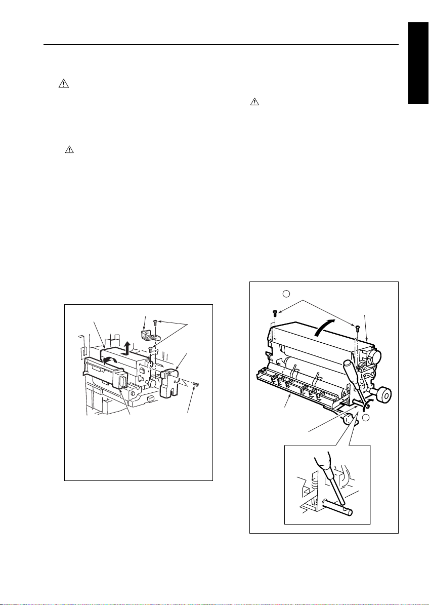
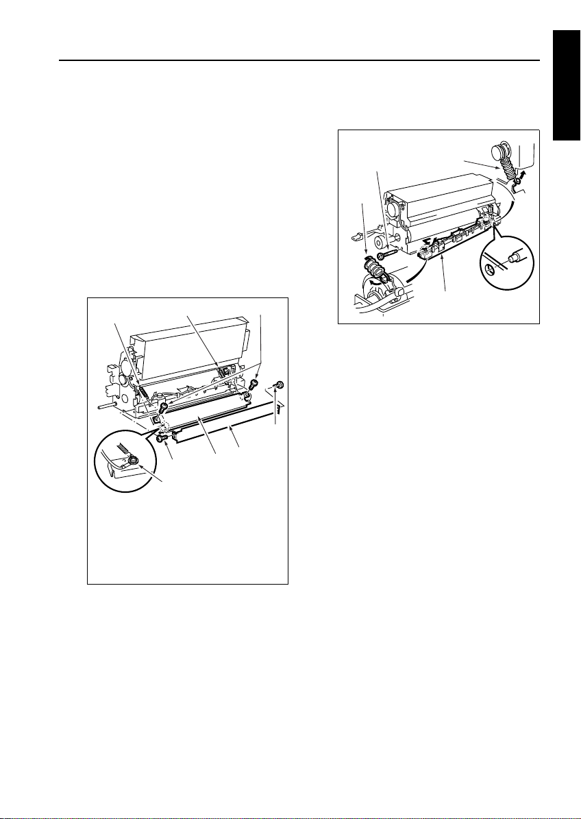
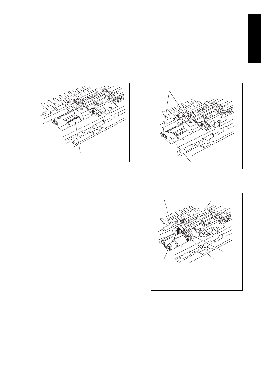
[1] Removing and Reinstalling the Fixing
Unit
Caution: Do not touch the fixing unit
a. Procedure
(1) Draw out the ADU stand. (See “ADU UNIT.”)
(2) Loosen two screws and detach the fixing unit
front cover.
(3) Open the paper reverse/exit unit.
(4) Remove one screw to detach the inlet guide plate
push-down lever.
(5) Remove one screw to draw out the fixing unit.
Then, remove it upward.
immediately after turning OFF
the main switch because it is
very hot and you may suffer
burns. Wait until the fixing
unit has cooled down sufficiently before working on it.
1
2
3
4
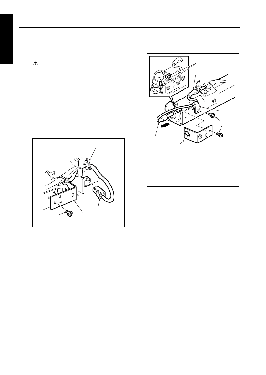
[2] Removing and Reinstalling the Fixing
Unit Top Cover
Caution: Before opening the fixing unit
a. Procedure
(1) Draw out the ADU stand. (See “ADU UNIT.”)
(2) Insert a screwdriver or the like in the hole in the
pressure release shaft and rotate the pressure
release shaft to release pressure.
Caution: Perform pressure release with the fix-
(3) Remove the four screws to open the fixing unit
top cover.
top cover, be sure to rotate the
pressure release shaft clockwise to release the lower roller.
After closing the fixing unit top
cover, be sure to rotate the
pressure release shaft counterclockwise to apply pressure to
the lower roller.
ing unit top cover closed.
2
Remove four screws.
Fixing unit top cover
1 DIS./ASSEMBLY
5
1. Fixing unit
2. Inlet guide plate push-down lever
3. Screws
4. Fixing unit front cover
5. Paper reverse/exit unit (open)
(1) Reinstall the above parts following the removal
steps in reverse.
3
1-O-1
Fixing paper
exit u nit
Pressure release shaft
1
Release
pressure.
Page 2
FIXING UNIT
(4) Close the fixing unit top cover following the open-
1 DIS./ASSEMBLY
ing steps in reverse.
Caution: When the fixing unit top cover has
been closed and secured with the four
screws, pressure must be applied to it
without fail.
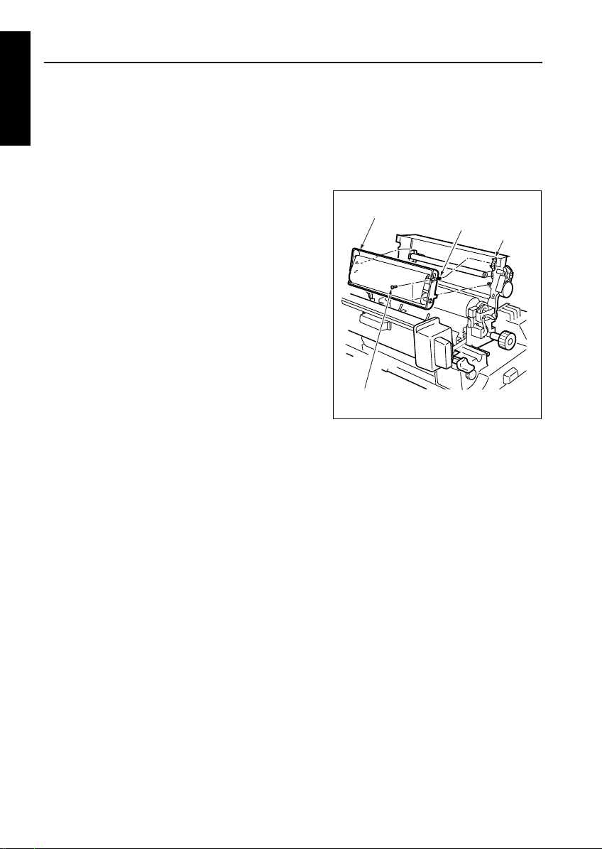
[3] Replacing the Cleaning Web
a. Procedure
(1) Draw out the ADU stand. (See “ADU UNIT.”)
(2) Open the fixing unit top cover.
(3) Remove the two screws to detach the cleaning
web unit.
Cleaning web unit
Screws (2)
(4) Reinstall the above parts following the removal
steps in reverse.
Caution1: When installing the cleaning web,
align the groove in the take-up gear
with the shaft pin on the unit, keeping
its tension.
Caution2: After replacing the cleaning web,
make sure to reset the count value of
the fixing unit cleaning web by “Copy
Count by Parts to be Replaced
(Fixed Parts)” in the 25 mode.
Pin
Gear groove
1-O-2
Page 3
FIXING UNIT
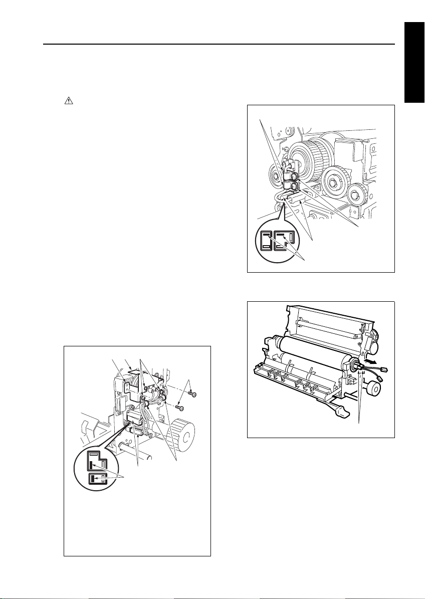
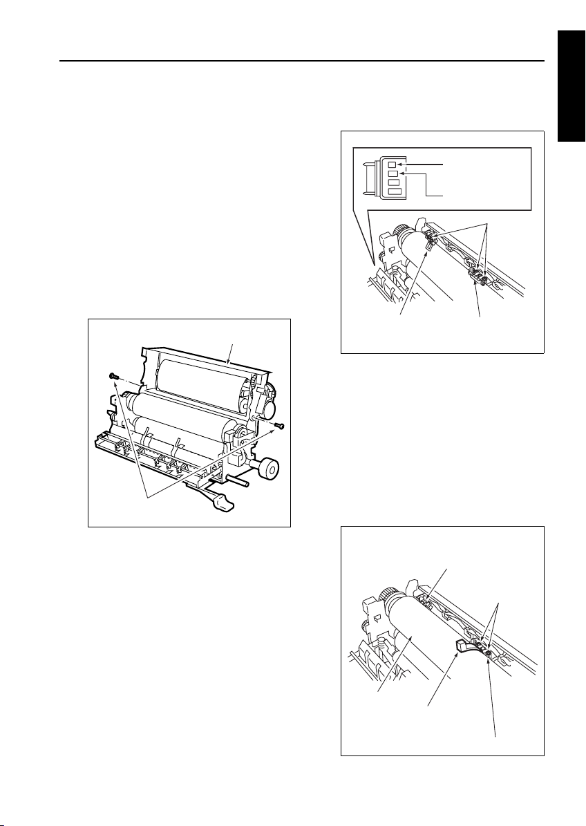
[4] Replacing the Fixing Heater Lamps
(Upper/Roller) (L2, L3)
Caution: Do not touch the fixing heater
Caution1: Install the heater lamp with the
Caution2: The heater lamp should not touch
Caution3: When replacing a heater lamp, be
a. Procedure
(1) Remove the fixing unit from the main body.
(2) Open the fixing unit top cover.
(3) Remove the two screws at the front to detach the
two wire harness clamps.
Caution: Install the wiring clamp screws
(4) Remove one screw and detach the lamp fixing
plate cover.
(5) Remove the two screws to detach the front lamp
fixing plate.
(6) Remove the two Faston terminals.
lamp with bare hands.
maker mark indication side facing
front.
the inner surface of the upper roller.
sure to insert the lamp end in the
lamp terminal securely.
through the lower mounting holes. If
installed through a wrong mounting
hole, the fixing unit front cover cannot
be installed.
3
2
1
(7) Remove the two screws at the back to detach two
wiring harness clamps.
(8) Remove the two Faston terminals at the back.
Wiring harness clamps (2)
Screws (2)
Faston terminals (2)
Faston terminals (remove 2)
(9) Pull out the fixing heater lamps (L2, L3) from the
front side of the fixing upper roller.
1 DIS./ASSEMBLY
5
6
1. Front lamp fixing plate
2. Lamp fixing plate cover
3. Screws
4. Wiring harness clamps
5. Faston terminals (2)
6. Faston terminals (remove)
3
Heater lamps (L2, L3)
(10) Reinstall the above parts following the removal
4
1-O-3
steps in reverse.
Caution: When installing new lamps, pay atten-
tion to their orientation. The size of the
lamp terminal mounting hole in the
front lamp fixing plate is different from
that in the rear lamp fixing plate. The
lamp inserted in the fixing upper roller
in the opposite direction cannot be
secured properly.
Page 4
FIXING UNIT
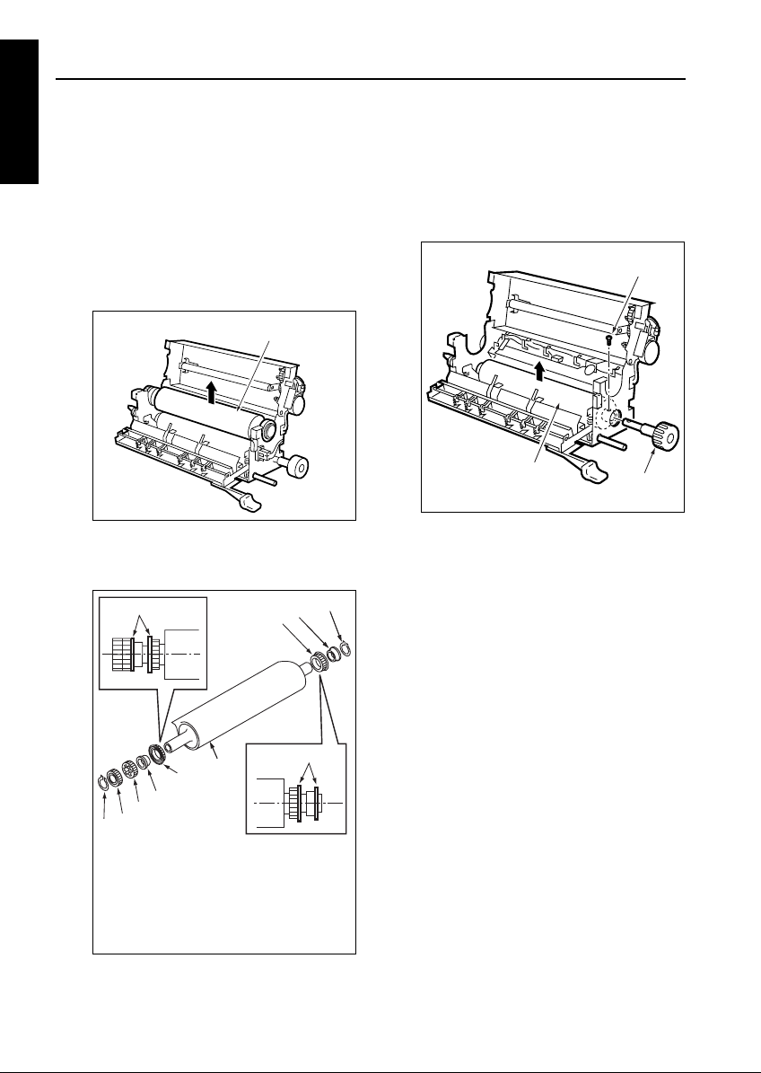
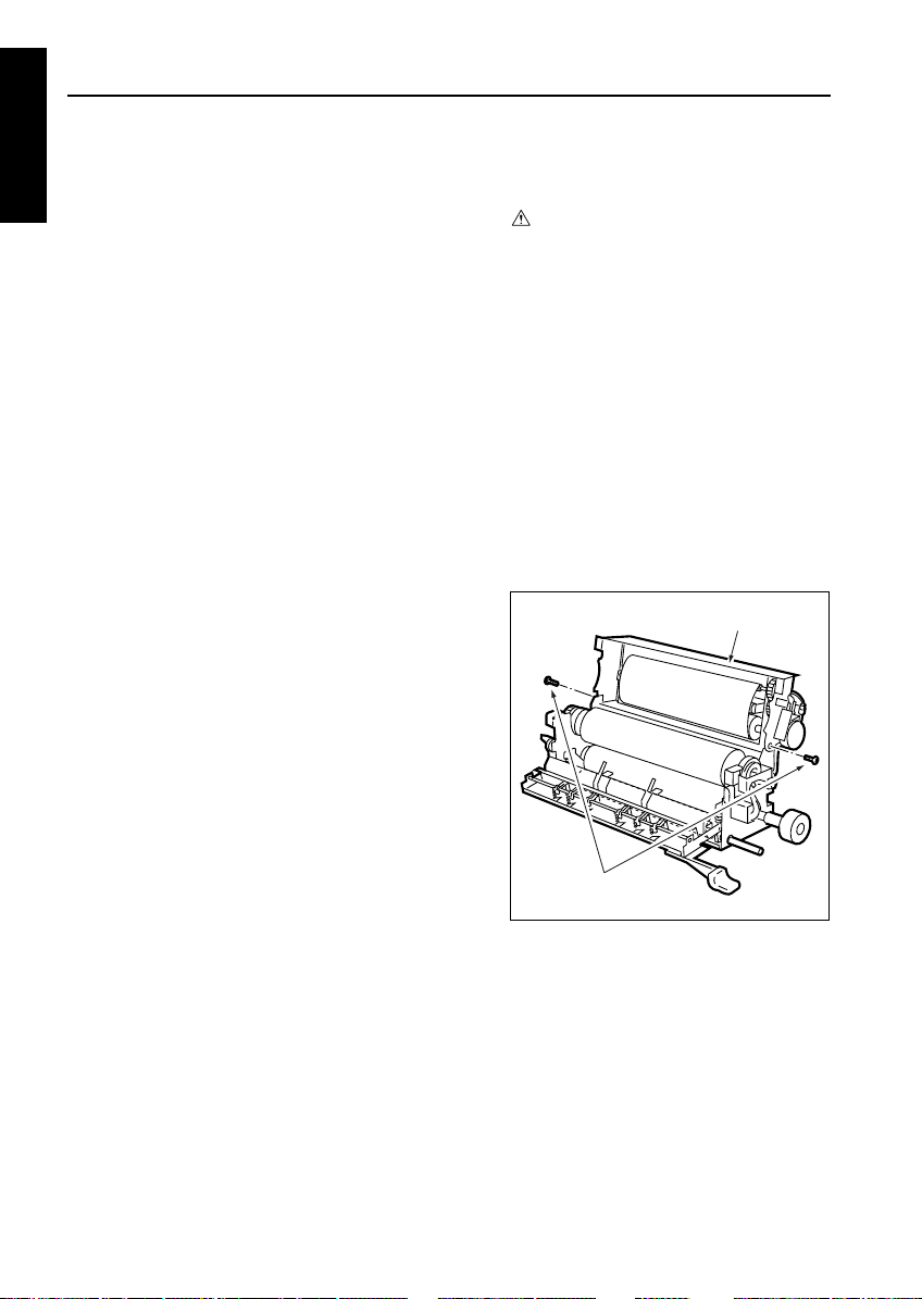
[5] Removing and Reinstalling the Fixing
1 DIS./ASSEMBLY
Upper Roller
a. Procedure
(1) Remove the fixing unit from the main body.
(2) Release the fixing unit lower contact with the
upper roller.
(3) Open the fixing unit top cover.
(4) Remove the fixing upper roller heater lamps (L2,
L3).
(5) Remove the fixing upper roller upward.
Fixing upper roller
(6) Remove the two C-rings, two gears, two bear-
ings, and two insulating sleeves from the fixing
upper roller.
1
2
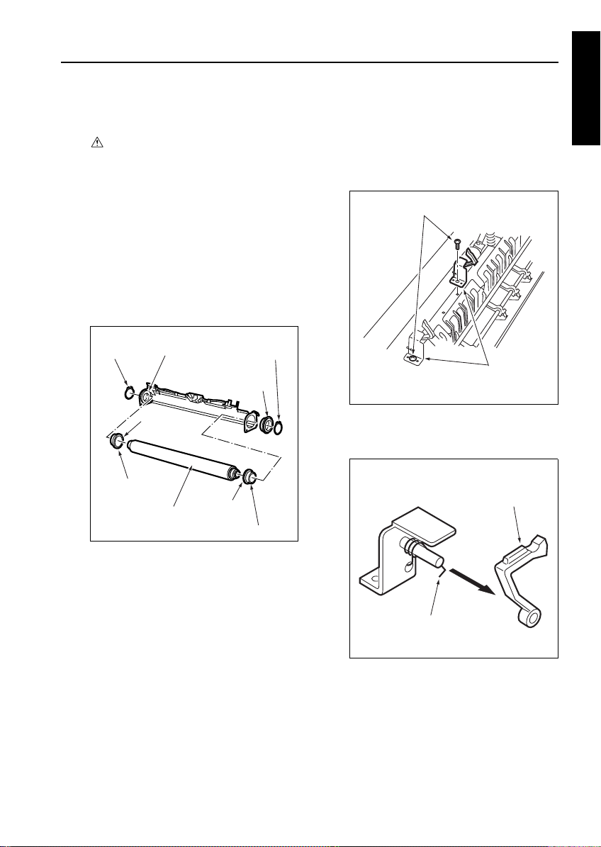
[6] Removing and Reinstalling the Fixing
Lower Roller
a. Procedure
(1) Remove the fixing upper roller.
(2) Remove one screw to detach the fixing knob.
(3) Remove the fixing lower roller upward.
Screw
Fixing lower roller
(4) Reinstall the above parts following the removal
steps in reverse.
4
3
Fixing knob
5
2
3
6
7
4
1. Collars
2. Bearing
3. Insulating sleeve
4. C-ring
5. Fixing upper roller
6. Gear (iron)
7. Gear (resin)
(1) Reinstall the above parts following the removal
steps in reverse.
1
1-O-4
Page 5
FIXING UNIT
[7] Removing and Reinstalling the Fixing
Heat Roller Assembly
a. Procedure
(1) Remove the fixing unit from the main body.
(2) Remove the two springs and one screw (along
with the ground cable) from the thick paper transport auxiliary plate.
Caution: The front and rear springs are different
(3) Remove the two shoulder screws to detach the
thick paper transport auxiliary plate.
(4) Remove the two screws to detach the fixing
plate.
in size and length. Install them properly.
1
1. Spring (short)
2. Spring (long)
3. Shoulder screws
4. Screw
5. Fixing plate
6. Thick paper transport auxiliary plate
7. Screw/ground wire
2
4
7
6
3
5
4
(1) Remove the two springs and one screw to detach
the fixing heat roller assembly.
Screw
Spring
Caution: When installing the fixing heat roller
assembly, be sure to fit the guide pin in
the guide hole on the rear side.
(2) Reinstall the above parts following the removal
steps in reverse.
Spring
Fixing heat roller
assembly
1 DIS./ASSEMBLY
1-O-5
Page 6
FIXING UNIT
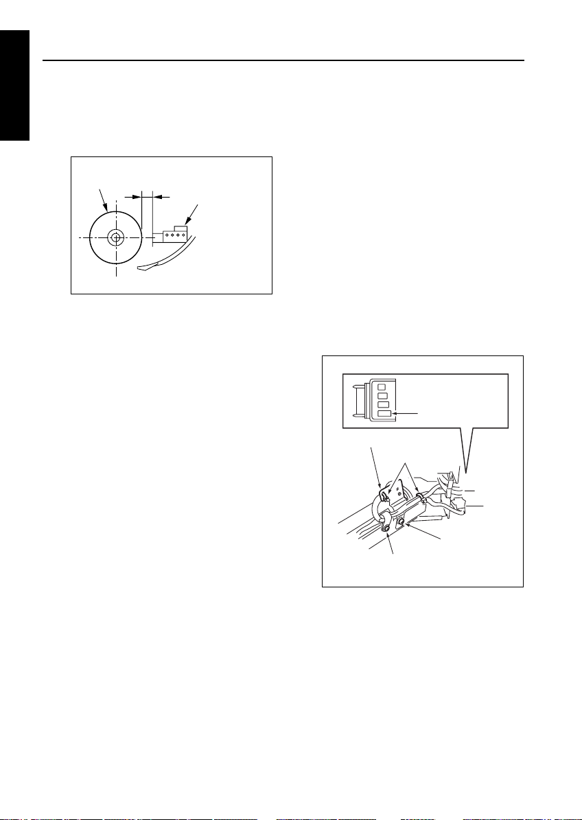
[8] Replacing the Heater Lamp (Heat
1 DIS./ASSEMBLY
roller) (L4)
Caution: Do not touch the fixing heater
Caution: Install the heater lamp (heat roller)
a. Procedure
(1) Remove the fixing heat roller assembly.
(2) Cut the insulating cable tie to disconnect the con-
nector (CN462).
(3) Remove one screw to detach the lamp fixing
plate (rear).
lamp (heat roller)(L4) with bare
hands.
(L4) with the maker mark indication
side facing front.
Cable tie (for heat insulation)
Connector
Screw
Lamp fixing plate (rear)
(6) Remove the heater lamp (L4) from the front side.
1
2
3
4
6
5
1. Cable ties (for heat insulation)
2. Faston terminal
3. Cable clamp (for heat insulation)
4. Screws
Lamp fixing plate (front)
5.
6. Heater lamp (L4)
(1) Reinstall the above parts following the removal
steps in reverse.
Caution: When reinstalling the lamp, pay atten-
tion to its orientation.
(4) Cut two insulating cable ties and remove the
screw securing the cable clamp to remove the
Faston terminal.
(5) Remove one screw to detach the lamp fixing
plate (front).
1-O-6
Page 7
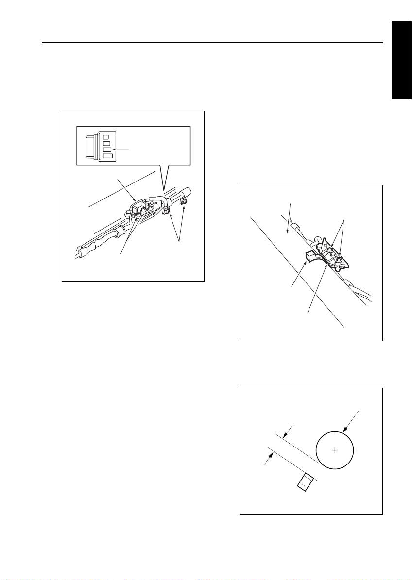
FIXING UNIT
[9] Removing and Reinstalling the Fixing
Heat Roller
Caution: Do not touch the fixing heater
a. Procedure
(1) Remove the fixing heat roller assembly.
(2) Remove the heater lamp (lower) (L4).
(3) Remove the two C-rings and the front bearing to
remove the fixing heat roller.
(4) Remove two insulating sleeves from the fixing
heat roller.
Caution: Reinstall the front and rear insulating
C-ring
Insulating sleeve
lamp (lower)(L4) with bare
hands.
sleeves with the collars facing toward
the fixing heat roller.
Bearing
Bearing
Collar
Fixing heat roller
Collar
Insulating sleeve
C-ring
[10] Removing and Reinstalling the Fixing
Separation Claws (Lower)
a. Procedure
(1) Open the fixing paper exit unit.
(2) Remove the two screws to detach the fixing sep-
aration claws (lower) assembly.
Screws
Fixing separation claws
(lower) assembly
(3) Remove the spring supporting each fixing sepa-
ration claw (lower).
(4) Remove the fixing separation claws (lower).
Fixing separation
claw (lower)
1 DIS./ASSEMBLY
(5) Reinstall the above parts following the removal
steps in reverse.
Spring/lower
(5) Reinstall the above parts following the removal
steps in reverse.
1-O-7
Page 8
FIXING UNIT
[11] Removing and Reinstalling the Fixing
1 DIS./ASSEMBLY
Separation Claws (Upper)
a. Procedure
(1) Open the fixing paper exit unit.
(2) Remove the six springs connected to the fixing
separation claws.
(3) Remove the six fixing separation claws.
Fixing
separation
claws
(upper)
Spring
(4) Reinstall the above parts following the removal
steps in reverse.
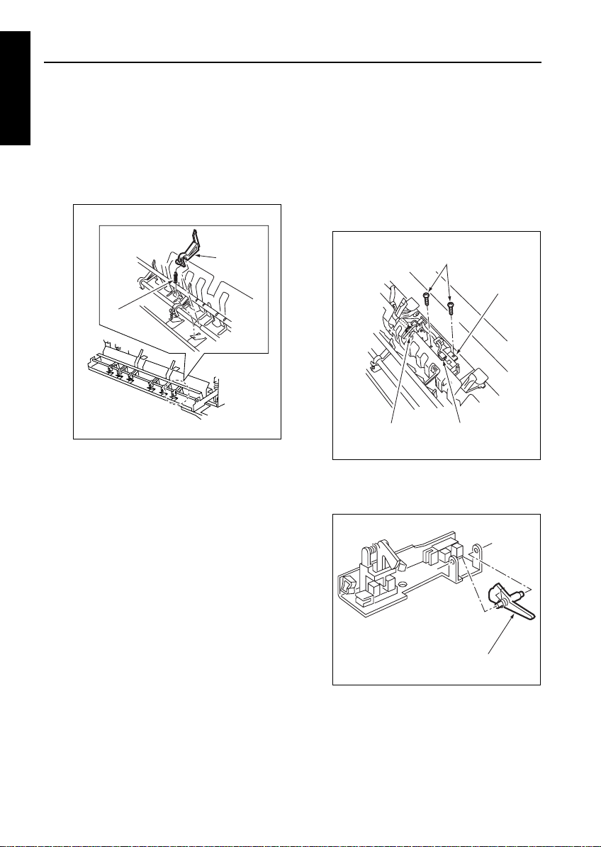
[12] Removing and Reinstalling the
Actuator for Fixing Exit PS (PS2)
a. Procedure
(1) Open the fixing paper exit unit.
(2) Disconnect the two connectors (CN464, 465).
(3) Remove one screw to detach the fixing separa-
tion claw (lower) (on the drive side).
(4) Remove the two screws to detach the actuator/
sensor assembly.
Screws
Connectors (CN464)Connectors
(CN465)
(5) Remove the spring from the actuator/sensor
assembly to detach the actuator for fixing exit PS
(PS2).
Actuator/
sensor
assembly
Fixing paper exit
actuator
(6) Reinstall the above parts following the removal
steps in reverse.
1-O-8
Page 9
FIXING UNIT
[13] Removing and Reinstalling Fixing
Temperature Sensors 1 and 2
Caution1: After reinstalling fixing temperature
sensor 2, make sure that the sensor
touches the fixing upper roller.
Caution2: Make sure the sensor wires do not
touch the fixing upper roller.
Caution3: When reinstalling fixing temperature
sensor 1, adjust its position using the
positioning jig (4014-5001-01) and
secure it with screws. Be sure to
apply screw lock agent to the screws.
a. Removal procedure
(1) Open the fixing unit top cover.
(2) Remove the two screws to detach the fixing unit
top cover.
Fixing unit top cover (upper)
Screws
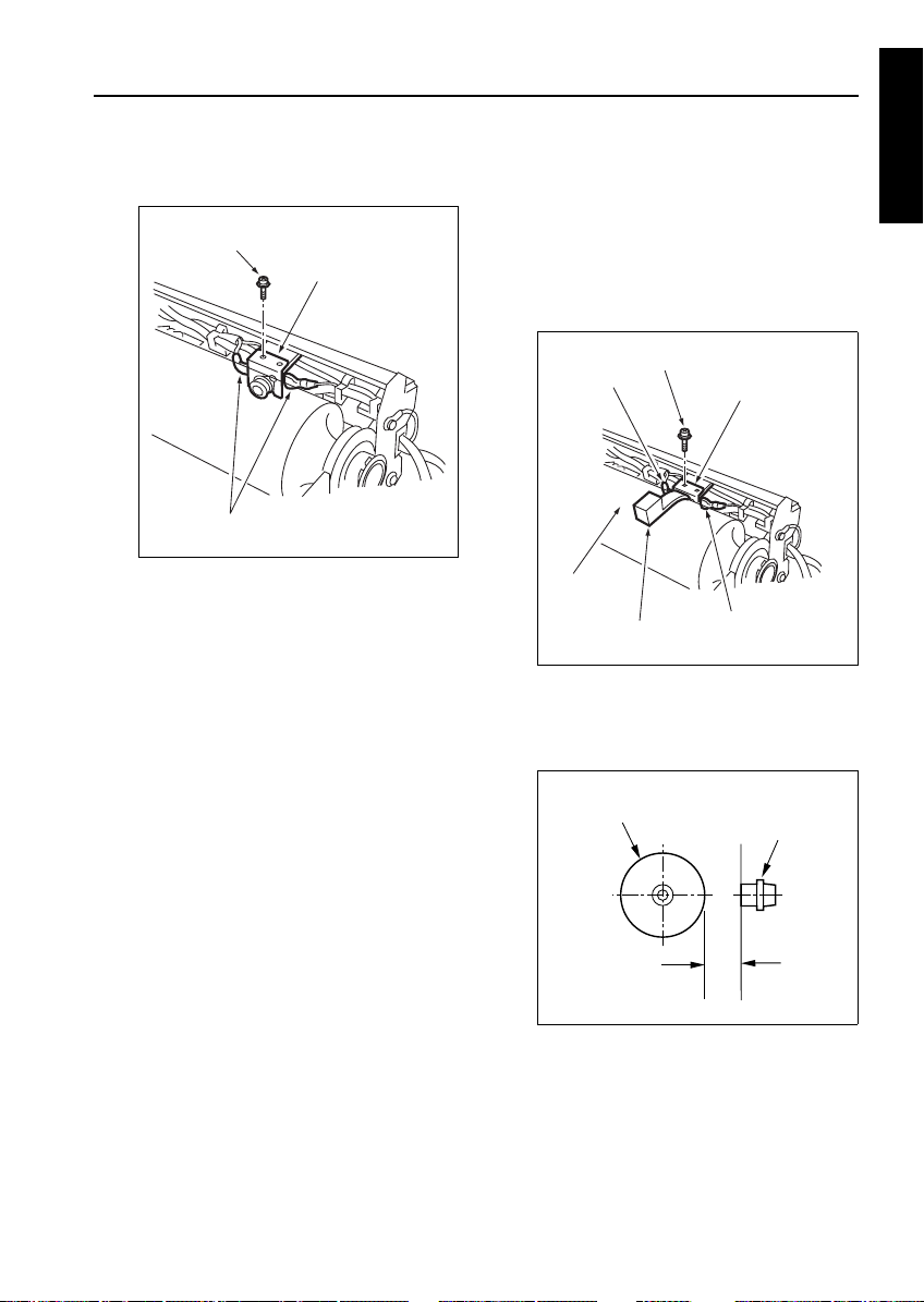
(5) Remove one screw (on the fixing plate side) to
detach fixing temperature sensor 2.
Fixing temperature
sensor 1 (CN466)
Fixing temperature
sensor 2 (CN467)
Screws
Fixing temperature
sensor 2
b. Reinstallation procedure
(1) Secure fixing temperature sensor 2 with a screw.
(2) Make sure that fixing temperature sensor 2
touches the fixing upper roller. If they do not
touch each other, be sure to bring the sensor in
touch with the roller.
(3) Set a fixing temperature sensor positioning jig
between fixing temperature sensor 1 and fixing
upper roller, and secure fixing temperature sensor 1 with two screws so that the distance
between the sensor and roller is equal to the
thickness of the jig.
Fixing temperature
sensor 1
1 DIS./ASSEMBLY
(3) Disconnect the two connectors (fixing tempera-
ture sensor 1, CN466; fixing temperature sensor
2, CN467) and release the sensor wires from the
cable guides.
(4) Remove the two screws to detach fixing temper-
ature sensor 1.
1-O-9
The fixing temperature sensor 2 must
contact the fixing upper roller.
Fixing upper
roller
Positioning jig
(4014-5001-01)
Fixing temperature sensor 1
Screws
Page 10
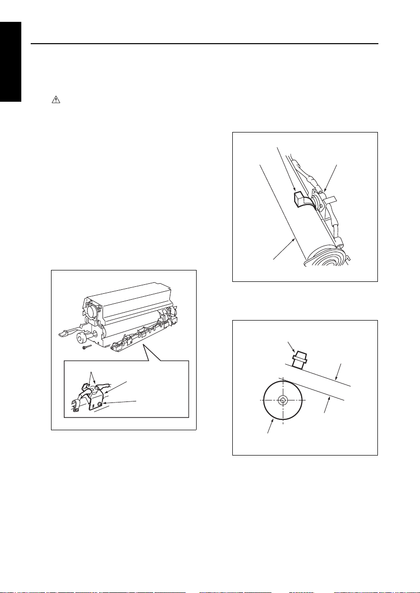
FIXING UNIT
a) Set the distance “a” between the fixing tem-
1 DIS./ASSEMBLY
perature sensor 1 and fixing upper roller so
that it is equal to the thickness of the positioning jig.
Fixing upper roller
Standard value of a: 0.75±0.1 mm
(4) Apply screw lock agent to the two screws secur-
ing fixing temperature sensor 1.
(5) Secure the wires of fusion temperature sensors
1 and 2 in the wire guides, and connect their con-
nectors.
(6) Reinstall other parts following the removal steps
in reverse.
Fixing temperature
sensor 1
a
[14] Removing and Reinstalling Fixing
Temperature Sensors 3 and 4
Caution1: After reinstalling fixing temperature
Caution2: Make sure the sensor wires do not
Caution3: When reinstalling fixing temperature
a. Removal procedure
(1) Remove the fixing heat roller assembly.
(2) Disconnect one connector (CN469), remove the
screw to detach the cable clamp, and cut insulating ties.
(3) Remove one screw (on the fixing plate side) to
remove fixing temperature sensor 4.
sensor 4, make sure that the sensor
touches the fixing heat roller (upper).
touch the fixing heat roller.
sensor 3, adjust its position using the
positioning jig (4014-5002-01) and
secure it with screws. Be sure to
apply screw lock agent to the screws.
Fixing
temperature
sensor 4
Fixing temperature
sensor 4
Cable ties
1-O-10
Screw
Screw/wiring harness clamp
Page 11
FIXING UNIT
(4) Disconnect one connector (CN468) and remove
four screws to detach two wire clamps.
(5) Remove the two screws to detach fixing temper-
ature sensor 3.
Fixing
temperature
sensor 3
Fixing temperature
sensor 3
Screw/wiring
Screws (2)
harness clamps
b. Reinstallation procedure
(1) Secure fixing temperature sensor 4 with a screw.
(2) Make sure that fixing temperature sensor 4
touches the fixing heat roller (upper). If they do
not touch each other, be sure to bring the sensor
in touch with the roller.
(3) Set a fixing temperature sensor positioning jig
between fixing temperature sensor 3 and fixing
heat roller, and secure fixing temperature sensor
3 with two screws so that the distance between
the sensor and roller is equal to the thickness of
the jig.
Fixing heat roller
Screws (two)
Positioning jig
(4014-5002-01)
Fixing temperature
sensor 3
a) Set the distance “a” between the fixing tem-
perature sensor 3 and fixing heat roller so that
it is equal to the thickness of the positioning
jig.
1 DIS./ASSEMBLY
1-O-11
Fixing heat roller
a
Fixing temperature sensor 3
Standard value of a = 0.7±0.1 mm
Page 12
FIXING UNIT
(4) Apply screw lock agent to the two screws secur-
1 DIS./ASSEMBLY
ing fixing temperature sensor 3.
(5) Secure the wires of fixing temperature sensors 3
and 4 with wire clamp and ties, and connect the
connectors.
(6) Reinstall other parts following the removal steps
in reverse.
[15] Removing and Reinstalling the
Thermostat (Upper)
Caution: This is an important safety part.
Be sure to observe the following cautions and steps when
removing or reinstalling.
Caution1: After reinstalling the thermostat
(upper), make sure that its wires do
not touch the fixing upper roller.
Caution2: When reinstalling the thermostat
(upper), adjust its position using the
thermostat PS jig/A (4014-5003-01)
and secure it with screws. Be sure to
apply screw lock agent to the screws.
Make this adjustment with pressure
applied.
a. Removal procedure
(1) Open the fixing unit top cover.
(2) Remove the two screws to detach the fixing unit
top cover.
Fixing unit top cover
1-O-12
Screws (2)
Page 13
FIXING UNIT
(3) Remove one screw and remove two Faston ter-
minals to detach the thermostat.
Screw
Thermostat (upper)
Faston terminals (2)
b. Reinstallation procedure
(1) Connect two Faston terminals to the thermostat
(upper).
(2) Set a thermostat positioning jig between the ther-
mostat (upper) and fixing upper roller, and
secure the thermostat (upper) with one screw so
that the distance between the roller and thermostat equal to the thickness of the jig.
Faston terminal
Fixing upper
roller
Thermostat PS jig/A
(4014-5003-01)
a) Set the distance “a” between the thermostat
(upper) and fixing upper roller so that it is
equal to the thickness of the thermostat PS
jig/A.
Screw
Thermostat (upper)
Faston terminal
1 DIS./ASSEMBLY
Fixing upper roller
Standard value of a = 3.0±0.2 mm
(3) Apply screw lock agent to the screw securing the
thermostat (upper).
(4) Reinstall other parts following the removal steps
in reverse.
1-O-13
Thermostat (upper)
a
Page 14
FIXING UNIT
[16] Removing and Reinstalling the
1 DIS./ASSEMBLY
Thermostat (Lower)
Caution: This is an important safety part.
Be sure to observe the following cautions and steps when
removing or reinstalling.
Caution1: After reinstalling the thermostat
(upper), make sure that its wires do
not touch the fixing heat roller.
Caution2: When reinstalling the thermostat
(upper), adjust its position using the
thermostat PS jig/B (4014-5004-01)
and secure it with screws. Be sure to
apply screw lock agent to the screws.
a. Removal procedure
(1) Remove the fixing heat roller assembly.
(2) Remove two Faston terminals from the thermo-
stat (lower).
(3) Remove one screw to detach the thermostat
(lower).
b. Reinstallation procedure
(1) Set a thermostat PS jig/B between the thermo-
stat (lower) and fixing heat roller, and secure the
thermostat (lower) with one screw so that the distance between the roller and thermostat equal to
the thickness of the jig.
Thermostat PS jig/B (4014-5004-01)
Thermostat (lower)
Fixing heat roller
a) Set the distance “a” between the thermostat
(lower) and fixing heat roller so that it is equal
to the thickness of the thermostat PS jig/B.
Thermostat (lower)
Faston terminal
Thermostat (lower)
a
Screw
Fixing heat roller
Standard: a = 3.0±0.20 mm
(2) Connect two Faston terminals to the thermostat
(lower).
(3) Apply screw lock agent to the screw securing the
thermostat (lower).
(4) Reinstall other parts following the removal steps
in reverse.
1-O-14
Page 15
EXTERNAL SECTION
RADF
Caution:
When disassembling and reassembling
the machine, Be sure the power cord has
been unplugged from the wall outlet.
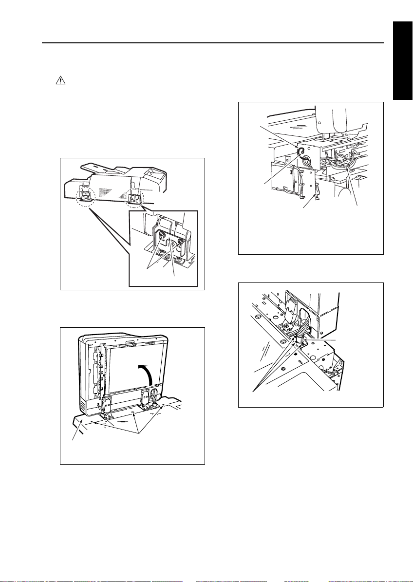
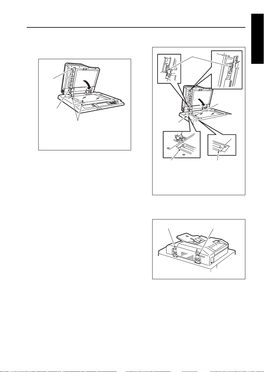
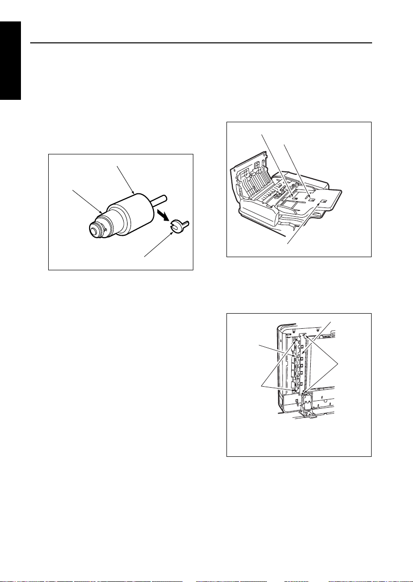
[1] Removing the RADF
a. Procedure
(1) Remove the rear cover.
(2) Remove two screws to detach the two stoppers.
Screws
(3) Open the RADF to the upright position.
(4) Remove the three screws to detach the top cover
(rear) of the main unit.
Stopper
(5) Remove the screw to disconnect the ground
cable.
(6) Remove the two relay connectors (CN31, CN32).
4
3
21
1. Relay connector (CN32)
2. Relay connector (CN31)
3. Screw
4. Ground cable
(7) Remove the three screws to detach the cable
conduit.
Cable conduit
3 DIS./ASSEMBLY1 DIS./ASSEMBLY
Top cover (rear)
Screws
(8) Draw the cable to the top of the main unit.
Screws
1-P-1
Page 16
RADF
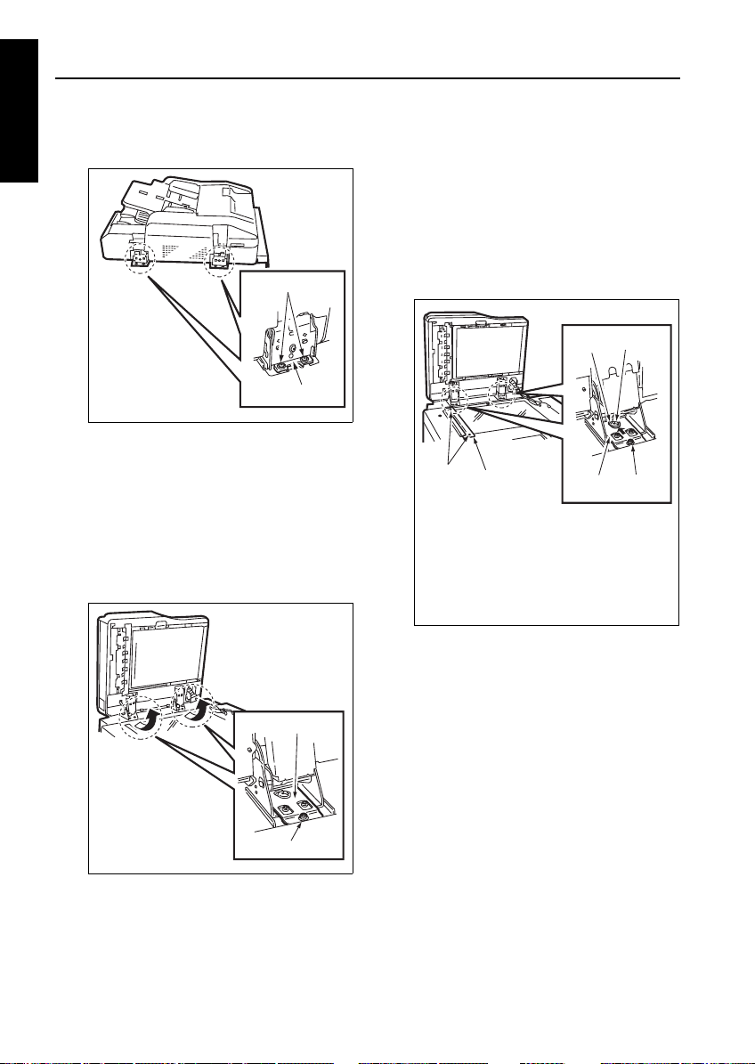
(9) Close the RADF. Remove the two screws to
3 DIS./ASSEMBLY1 DIS./ASSEMBLY
detach each of the two fixing plates (R).
Fixing plate (R)
(10) Open the RADF up to the upright position.
(11) Holding the RADF, remove one screw to detach
each of two fixing plates.
(12) Holding the RADF, remove it from the main unit.
Caution: When the fixing plates (F) are
removed, the RADF may fall down to
the rear side. Be sure to hold the
RADF while performing steps 11 and
12.
Fixing plate (F)
Screws
[2] Reinstalling the RADF
a. Procedure
(1) Place the RADF on the top of the main unit and
loosely secure each of the two fixing plates (F)
with one screw.
Note: The necked hole in the fixing plate (F)
(2) Remove the two screws to detach the original
(3) Following the removal procedure in reverse,
(4) Install two RADF positioning jigs in the mounting
must fit over the guide screw.
stopper plate (left).
4
3
2
1
1. Original stopper plate (left)
2. Screws
3. Necked hole
4. Guide screw
5. Screws (tighten temporarily)
6. Fixing plate (F)
install the cable conduit, two relay connectors
(CN31, CN32), ground cable, and top cover
(rear) of the main unit.
holes of the original stopper plate (left).
6
5
Screw
1-P-2
Page 17
RADF
(5) Close the RADF to mate the reference holes and
RADF positioning jigs.
3
2
1
1. RADF positioning jigs
2. Reference hole (oblong hole)
3. Reference hole (round hole)
(6) Install two screws to secure each of the two fixing
plates (R) following the removal procedure in
reverse.
(7) Open the RADF, install the other screw for each
of the two fixing plates (F), and finally tighten all
the four screws to secure the two fixing plates
(F).
(8) Remove the RADF positioning jigs and install the
original stopper plate (left) with two screws.
(9) Close the RADF and check whether both stopper
pieces on the RADF-side touch the slit glass.
Note: The state of contact between the stopper
pieces and the silt glass can be checked
by looking into the slits in the top cover of
the main unit.
1
2
4
3
1. Stopper piece
2. Slit glass
3. Slit
4. Top cover (middle)
(10) If both stopper pieces do not touch the slit glass
at the same time, make adjustments using
adjusting screws A and B alternately.
Adjusting screws B Adjusting screws A
3
3 DIS./ASSEMBLY1 DIS./ASSEMBLY
(11) Perform steps (9) and (10) repeatedly until the
two stopper pieces touch the slit glass at the
same time.
(12) Install the rear cover of the main unit.
1-P-3
Page 18
RADF
ORIGINAL FEED/CONVEYANCE/EXIT SECTION
3 DIS./ASSEMBLY1 DIS./ASSEMBLY
Caution:
When disassembling and reassembling
the machine, Be sure the power cord has
been unplugged from the wall outlet.
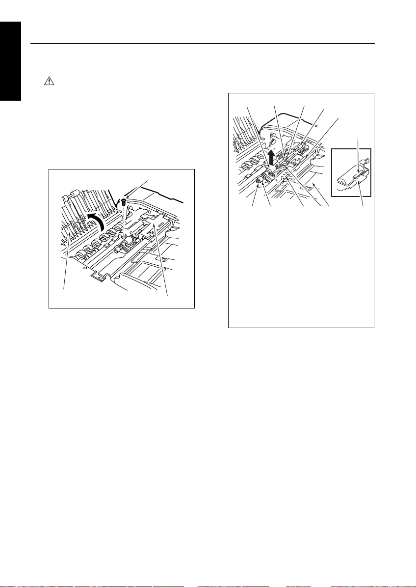
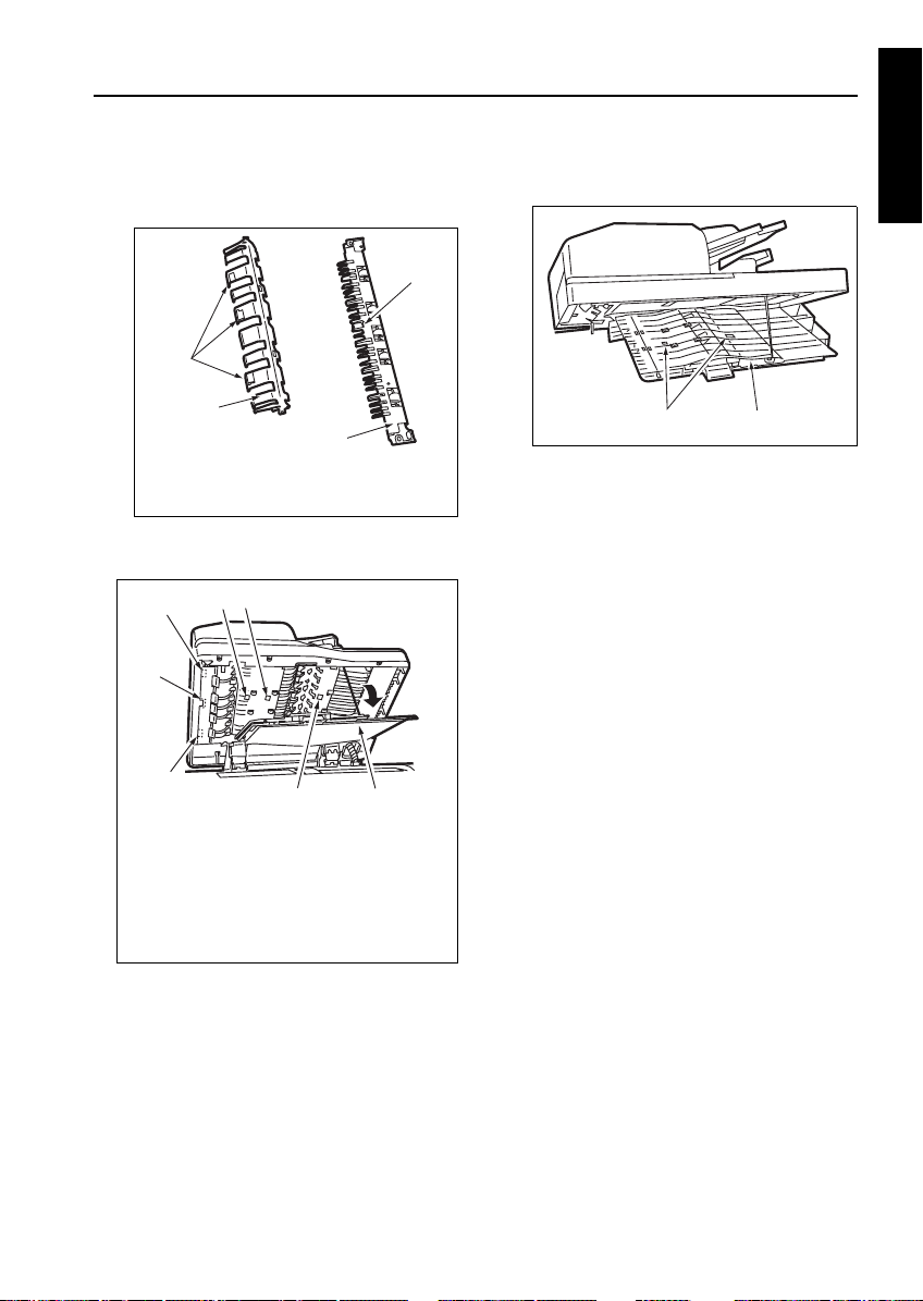
[1] Replacing the Pickup Roller and Con-
veyance Roller Rubber
a. Procedure
(1) Open the Jam access cover.
(2) Remove the screw to detach the sensor cover.
Screws
Jam access cover
(3) Remove the spring.
(4) Remove the two stop rings to slide the bearing
and one-way clutch outward.
(5) Slide the original feed roller unit to the front to
release it from the coupling, then remove it
upward.
Sensor cover
(6) Remove the original feed roller rubber from the
original feed roller.
2
1
389
1. Original feed roller unit
2. Bearing
3. Stop ring
4. Coupling
5. Stay
6. Original feed tray
7. Spring
8. Angled portion
9. One-way clutch
10. Angled portion of original feed roller unit
11. Angled portion of stay
(7) Clean rollers using a blower brush or the like.
(8) Reinstall the original feed roller unit in the
reverse order of the removal procedure.
Note: Caution:Make sure the angled portion of the
original feed roller unit is positioned above the
angled portion of the stay. If the angled portion
of the original feed roller unit is positioned
below the angled portion of the stay, originals
are not fed properly.
3
4
5
10
67
11
1-P-4
Page 19
RADF
[2] Cleaning the Cleaning Pad
a. Procedure
(1) Open the movable cover.
(2) Remove one screw to detach the cleaning pad.
(3) Using a blower brush, clean the cleaning pad.
1
2
4
1. Screw
2. Cleaning pad
3. Movable cover
4. Registration roller
(4) Reinstall the above parts following the removal
steps in reverse.
3
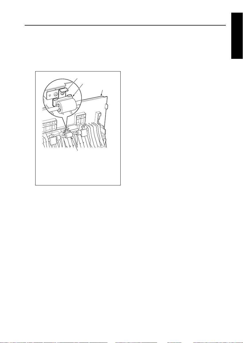
[3] Replacing the Original Feed Roller/
Separation Roller/Auxiliary Separation Roller
a. Procedure
(1) Remove the original feed roller unit.
(2) Remove the one-way clutch.
(3) Remove stop ring (1) to detach gear (1) and belt.
(4) Remove stop ring (2) and pull out shaft (1) to
detach the original feed roller.
(5) Pull the pin for gear (1) and the spacer from shaft
(2).
(6) Remove stop rings (3), (4), and (5) to pull the pin
for gear (2) from shaft (2).
(7) Pull out shaft (2) to detach the separation roller.
(8) Remove stop ring (6) to pull the pin for gear (3)
from shaft (3).
3 DIS./ASSEMBLY1 DIS./ASSEMBLY
1-P-5
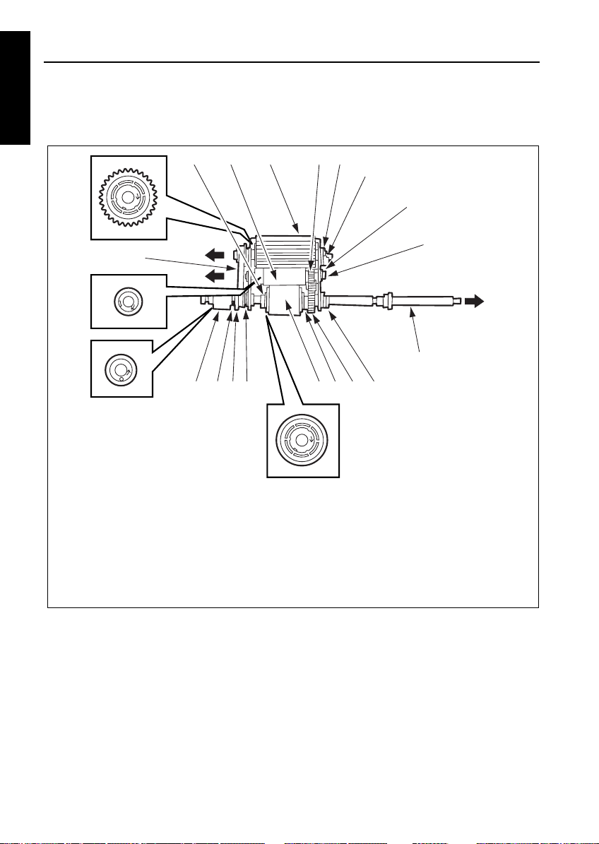
Page 20
RADF
(9) Pull out shaft (3) to detach the auxiliary separa-
3 DIS./ASSEMBLY1 DIS./ASSEMBLY
tion roller.
21
18
17 131416 15
1. Stop ring (3)
2. Auxiliary separation roller
3. Original feed roller
4. Gear (3) (with a pin)
5. Shaft (1)
6. Stop ring (2)
7. Stop ring (6)
8. Shaft (3)
9. Shaft (2)
53
4
6
12
1011
10. Stop ring (5)
11. Gear (2) (with a pin)
12. Stop ring (4)
13. Separation roller
14. Spacer
15. Gear (1) (with a pin)
16. Stop ring (1)
17. One-way clutch
18. Belt
7
8
9
(10) Reinstall the original feed roller/separation roller/
auxiliary separation roller in the reverse order of
the removal procedure.
Caution: Make sure the one-way clutch and roll-
ers are oriented properly when reinstalling them.
1-P-6
Page 21
RADF
[4] Cleaning the Paper Separation Rub-
ber
a. Procedure
(1) Remove the original feed roller unit.
(2) Clean the paper separation rubber using a drum
cleaner and cleaning pad.
Paper separation rubber
(3) Reinstall the cleaning roller in the reverse order
of the removal procedure.
[5] Replacing the Double Feed Preven-
tion Roller/Torque Limiter
a. Procedure
(1) Remove the original feed roller unit.
(2) Remove the two screws to detach the auxiliary
roller assembly.
Screws
Auxiliary roller assembly
(3) Remove the stop ring to detach the gear.
(4) Slide the two bearings outward to detach the
double feed prevention roller unit.
1
2
3 DIS./ASSEMBLY1 DIS./ASSEMBLY
1-P-7
2
1. Double feed prevention unit
2. Bearing
3. Stop ring
4. Gear
4
3
Page 22
RADF
(5) Remove the stop ring to detach the double feed
3 DIS./ASSEMBLY1 DIS./ASSEMBLY
prevention roller and torque limiter.
(6) Reinstall the double feed prevention roller and
torque limiter in the reverse order of the removal
procedure.
Note: Make sure the double feed prevention
roller is oriented properly when reinstalling it.
Double feed prevention roller
Torque limiter
Stop ring
[6] Cleaning Photo Sensors/Mirrors for
Photo Sensors
a. Procedure
(1) Close the RADF.
(2) Clean sensors using a blower brush or the like.
PS310 (Original count detection)
PS303 (Original size detection 2)
PS303 (Original size detection 1)
(3) Open the RADF.
(4) Remove the two screws to detach the driven
roller assembly.
(5) Remove the two screws to detach the original
conveyance guide.
1
3
1-P-8
2
2
1. Driven roller assembly
2. Screws
3. Original conveyance guide
Page 23
RADF
(6) Using a blower brush or the like, clean the mirror
on the driven roller assembly and the three mirrors on the original conveyance guide.
1
1
3
1. Mirror
2. Driven roller assembly
3. Original conveyance guide
(7) Open the platen guide.
(8) Clean sensors using a blower brush or the like.
1
7
2
2
6
5
34
1. PS309 (Original reversal detection)
2. PS304 (Reverse jam detection)
3. Platen guide
4. PS313 (Original exit reverse detection)
5. PS312 (Original skew detection 2)
6. PS308 (Original conveyance detection PS)
7. PS311 (original skew detection 1)
(9) Clean the two mirrors on the back of the platen
guide using a blower brush or the like.
Mirrors
(10) Reinstall the photo sensors/mirrors for photo
sensors in the reverse order of the removal pro-
cedure.
Platen guide
3 DIS./ASSEMBLY1 DIS./ASSEMBLY
1-P-9
Page 24

3 DIS./ASSEMBLY1 DIS./ASSEMBLY
Page 25

PAPER FEED SECTION
LCT
Caution:
If LCT is connected to the main body, make
sure that main body power plug is disconnected from the power outlet.
[1] Cleaning the Paper Dust Removing
Brush
a. Procedure
(1) Open the top cover.
(2) Remove six screws to detach the paper feed
cover B.
Top cover
Screws
Paper feed cover B
(3) Insert a flat bladed screwdriver in the cavities (in
two locations) for paper dust removing brush to
release the locking lugs, then remove the paper
dust removing brush.
Paper dust removing brush
[2] Cleaning the LT feed PS (PS106)/LT
first paper feed PS (PS107)
a. Procedure
(1) Looking into the paper exit side of the LCT from
below, and clean sensors through the cavity for
LT feed PS (PS106) and the cavity for LT first
paper feed (PS107) using a blower brush.
Cavity for PS106
Cavity for PS107
Paper exit side
3 DIS./ASSEMBLY1 DIS./ASSEMBLY
Locking lugs
(4) Clean the paper dust removing brush using a
blower brush.
(5) Reinstall the above parts following the removal
steps in reverse.
Cavity
1-Q-1
Page 26

LCT
[3] Removing and Reinstalling the Paper
3 DIS./ASSEMBLY1 DIS./ASSEMBLY
Feed Roller Unit
a. Procedure
(1) Open the top cover.
(2) Remove the spring from the paper feed roller
unit.
Top cover
Spring
Paper feed roller unit
Paper feed roller unit
(3) After removing two stop rings, remove the two
bearings outward to remove the paper feed roller
unit.
Paper feed roller unit
Remove
this
[4] Replacing the Paper Feed Roller Rub-
ber/Feed Roller Rubber
a. Procedure
(1) Remove the paper feed roller unit.
(2) Remove the bearing and paper feed reference
actuator.
Paper feed reference actuator
Bearing
(3) Remove two stop rings.
(4) Remove two bearings outward to detach the
roller section from the roller fitting.
Roller fitting
Stop rings
Bearing
Bearing
Stop ring
(4) Reinstall the above parts following the removal
steps in reverse.
Bearing
Stop ring
Bearing
1-Q-2
Page 27

LCT
(5) Remove the bearing from the opposite side of the
coupling, then remove the paper feed roller from
the shaft.
(6) Remove the stop ring to pull the feed roller from
the shaft.
(7) Remove the rubber from each roller.
4
3
2
1
5
3
6
7
8
1. Paper feed roller
2. Paper feed roller rubber
3. Shaft
4. Coupling
5. Feed roller
6. Feed roller rubber
7. Stop ring
8. Bearing
Paint mark
[5] Replacing the Double Feed Preven-
tion Roller Rubber
a. Procedure
Caution: With the power held on, press the LT
tray down switch (SW100) to move the
up/down plate down to the bottom in
advance.
(1) Remove the paper feed roller unit.
(2) Remove two screws to detach the double feed
prevention roller unit cover.
2
1
3
1. Double feed prevention roller
2. Double feed prevention roller unit cover
3. Screws
3 DIS./ASSEMBLY1 DIS./ASSEMBLY
(8) Reinstall the above parts following the removal
steps in reverse.
Caution1: Make sure rollers and rubber por-
tions are oriented properly when
reinstalling them.
Caution2: Make sure the one-way clutch direc-
tion is correct.
Caution3: Check whether grease or the like is
present on each roller.
1-Q-3
Page 28

LCT
(3) Remove two screws to detach the double feed
3 DIS./ASSEMBLY1 DIS./ASSEMBLY
prevention roller unit.
Caution: When reinstalling the double feed pre-
vention roller unit, tighten the screws
on the rear side first.
Double feed prevention roller unit
(4) Remove two stop rings, fit the shaft into the D-cut
in the fitting, and remove the double feed prevention roller together with the shaft.
Double feed prevention roller
Screws
D-cut
(5) Remove the double feed prevention roller rubber
from the double feed prevention roller.
Pain t mar k
1
2
3
1. Double feed prevention roller
2. Shaft
3. Double feed prevention roller rubber
(6) Reinstall the double feed prevention roller in the
reverse order of the removal procedure.
Caution1: Make sure the double feed preven-
tion roller rubber is oriented properly
when reinstalling it.
Caution2: Check whether scratch or the like is
visible on the pet cover for the drive
gear.
Caution3: Check whether grease or the like is
present on double feed prevention
roller.
Stop rings
1-Q-4
Page 29

LCT
[6] Replacing the LT feed MC (MC101)/LT
first paper feed MC (MC102)
a. Procedure
(1) Open the top cover.
(2) Remove the spring from the paper feed roller
unit.
(3) Remove two screws to detach the top cover.
Top cover
Screws
(4) Remove three screws to detach the clutch
replacement cover.
Clutch replacement cover
Screws
(5) Disconnect two relay connectors (CN765,
CN766) of the clutches.
(6) Remove the stop ring to detach each clutch.
3
2
1
1
5
4
1. Stop ring
2. LT feed MC (MC101)
3. LT first paper feed MC (MC102)
4. Relay connector (CN765)
5. Relay connector (CN766)
(7) Reinstall the above parts following the removal
steps in reverse.
Caution: When installing each MC, make sure
that the stopper of each clutch is on
the predefined position.
3 DIS./ASSEMBLY1 DIS./ASSEMBLY
1-Q-5
Page 30

LCT
[7] Replacing the C-403 Up/Down Wires
3 DIS./ASSEMBLY1 DIS./ASSEMBLY
Caution: With the power held on, press the LT
tray down switch (SW100) to move the
up/down plate down to the bottom in
advance.
a. Procedure
(1) Open the top cover.
(2) Remove the clutch replacement cover.
(3) Remove five screws to detach the right side
cover.
Right side cover
(4) After opening the jam access door, remove six
screws to detach the front cover.
Caution: When removing the front cover, close
the jam access door after removing
the screws.
Jam access door
Screws
Screws
(5) Remove twelve screws to detach the rear cover.
Screw
Screws
Screws
Rear cover
(6) Remove the five relay connectors (CN749,
CN780, CN781, CN782, CN783) to disconnect
the wiring harness from the up/down motor
mounting assembly.
(7) Remove the E-ring to detach the up/down gear.
(8) Pull the pin from the shaft.
(9) Remove the E-ring to detach the bearing.
Screws
Screws
Screws
Right side cover
1-Q-6
Page 31

LCT
(10) Remove three screws to detach the up/down
motor assembly.
3
1
2
4
5
6
7
3
12
8
3
11
9
9
10
1. Up/down motor mounting assembly
2. Relay connector (CN749)
3. Screw
4. Relay connector (CN780)
5. Relay connector (CN781)
6. Relay connector (CN782)
7. Relay connector (CN783)
8. Up/down gear
9. E-ring
10. Pin
11. Bearing
12. Shaft
(11) Replace the up/down wire following the instruc-
tions in “Removing Up/Down Wires’’ and “Installing Up/Down Wires.’’
Caution: Two sets of four up/down wires with
different length, one set at the front
and the other at the back, are used.
Wires with the same length can be
used either at the front or back if they
are used in the same location.
1323.6 mm
Wire A
1250.3 mm
Wire B
769.3 mm
Wire C
661 mm
Wire D
3 DIS./ASSEMBLY1 DIS./ASSEMBLY
1-Q-7
Page 32

LCT
<Removing the Up/Down Wires>
3 DIS./ASSEMBLY1 DIS./ASSEMBLY
Up/down plate
Wire B
Wire A
14.Release the metal
ball to remove wire A.
7.Release the metal ball
to remove wire C.
9.Release the metal ball
to remove wire D.
12.Release the metal
ball to remove wire B.
Wire C
Wire D
6.Remove the E-ring.
8.Remove the pulley.
10.Remove the pulley.
Wire B
Wire A
FRONT
Wire D
Up/down shaft
2.Release the metal ball
to remove wire C.
18.Release the metal ball
to remove wire A.
4.Release the metal ball
to remove wire D.
16.Release the metal
ball to remove wire B.
Wire C
1.Remove the E-ring.
3.Remove the pulley.
5.Remove the pulley.
15.Remove the E-ring,
then remove the pulley
to release wire B.
11.Remove the E-ring,
then remove the pulley
to release wire B.
13.Remove the pulley to
release wire A.
1-Q-8
17.Remove the pulley to
release wire A.
Page 33

<Installing the Up/Down Wires>
Wire B
Wire A
7.Insert wire A in the pulleys, then attach a
metal ball.
15.Insert wire C in the pulleys, then attach a
metal ball.
12.Insert wire D in the pulleys, then attach a
metal ball.
10.Insert wire B in the pulleys, then attach a
metal ball.
Wire C
Wire D
13.Insert wire C in the up/
down shaft, attach a pulley,
and secure the pulley with
an E-ring.
14.Wind wire C around the pulley by 6 turns in such a manner that the wire can be
pulled from over the pulley.
Wire B
Wire A
FRONT
Up/down plate
1.
6.
Insert wire A in
the up/down
shaft, attach pulleys, then pull the
wire A from under
the pulleys.
20.Insert wire B in the pulleys,
then attach a metal ball.
2.Insert wire A in the pulleys, then
attach a metal ball.
17.Insert wire D in the pulleys,
then attach a metal ball.
5.Insert wire B in the pulleys, then
attach a metal ball.
Wire D
Wire C
Up/down shaft
18.Insert wire C in the up/
down shaft, attach a pulley, and secure the pulley
with an E-ring.
19.Wind wire C around the
pulley by 6 turns in su ch a
manner that the wire can
be pulled from over the
pulley.
LCT
3 DIS./ASSEMBLY1 DIS./ASSEMBLY
6 turns
6 turns
11.Insert wire D in the up/down
shaft, attach a pulley, and
wind wire D around the pulley by six turns in such a
manner that the wire can be
pulled from over the pulley.
6 turns
Insert wire B in the up/down
3.
shaft, attach a pulley, and
8.
secure the pulley with E-rings.
d
n
u
m
o
r
f
B
4.
9.
e
r
i
l
w
u
l
P
.
s
y
l
e
1-Q-9
16.Insert wire D in the up/
down shaft, attach a pulley, and wind wire D
around the pulley by six
turns in such a manner
that the wire can be
pulled from over the pul-
-
l
p
u
h
e
t
r
e
ley.
6 turns
Page 34

LCT
(12) After installing the up/down wires, make sure the
3 DIS./ASSEMBLY1 DIS./ASSEMBLY
up/down wires are passed in the grooves in the
pulleys properly and wires do not run on the
sides of the pulleys. Also make sure the up/down
plate can be moved up and down smoothly by
hand.
Caution: If the up/down plate does not move up
(13) Install the up/down wire drive motor assembly,
up/down gear, and relay connectors, following
the removal steps in reverse.
(14) Remove the E-ring to detach the idle gear.
(15) Rotate the remaining paper detection gear until
the round hole in this gear is aligned with the
oblong hole in the up/down motor mounting
assembly.
Caution: Align when the up/down plate is in low-
and down smoothly, reinstall the up/
down wires.
est position.
1
6
1. Up/down motor mounting assembly
2. Remaining paper detection gear
3. Round hole
4. Oblong hole
5. E-ring
6. Idle gear
2
5
[8] Replacing the C-404 Up/Down Wires
a. Procedure
Caution: With the power held on, press the LT
(1) Remove the clutch replacement cover, side
cover (right), front cover, and rear cover following
the steps (1) to (5) in [7] Replacing the C-404 Up/
Down Wires.
(2) Remove the E-ring.
(3) Remove the five screws to detach the gear cover.
(4) Remove the two bearings.
(5) Remove the gear A.
(6) Remove the E-ring to remove gear B.
3
4
(7) Remove the detent pin for gear B from the up/
down pulley shaft.
(8) Remove the E-ring and bearing to remove gear
C.
tray down switch (SW100) to move the
up/down plate down to the bottom in
advance.
E-ring
Bearing
Screws
Bearing
Screw
Screw
Gear cover
Bearing
Gear C
(16) Install the idle gear.
(17) Attach the covers following the removal steps in
reverse.
Caution1: After replacing the up/down wires,
make horizontal and centering
adjustment of the up/down plate.
(Refer to “ADJUSTMENT SECTION.”)
1-Q-10
Gear A
Pin
Gear B
E-ring
E-ring
Up/down pulley shaft
Page 35

LCT
(9) Remove the bearing behind gear C.
(10) Remove the E-ring to remove the up/down gear.
(11) Remove the detent pin for up/down gear from the
up/down pulley shaft.
(12) Remove the E-ring to remove gear D.
(13) Remove the E-ring to remove the remaining
paper detection gear.
(14) Remove four relay connectors (CN780, CN781,
CN782, and CN783) to disconnect the wiring
harness from the up/down motor mounting
assembly.
3
2
1
4
5
12
7
11
10
7
9
1. Remaining paper detection gear
2. Relay connector (CN780)
3. Relay connector (CN781)
4. Relay connector (CN782)
5. Up/down motor mounting assembly
6. Relay connector (CN783)
7. E-ring
8. Bearing
9. Up/down pulley shaft
10. Up/down gear
11. Pin
12. Gear D
8
6
7
(15) Remove the E-ring to remove the bearing.
(16) Remove the six screws to remove the up/down
motor mounting assembly.
Up/down motor mounting assembly
Screws
Bearing
E-ring
(17) Replace the up/down wires following the instruc-
tions in “Removing the Up/Down Wires” and
“Installing Up/Down Wires.”
Caution: Two sets of four up/down wires with
different length, one set at the front
and the other at the back, are used.
Wires with the same length can be
used either at the front or back if they
are used in the same location.
1057.3 mm
Wire A
692.1 mm
Wire B
1321.7 mm
Wire C
1303.1 mm
Screws
3 DIS./ASSEMBLY1 DIS./ASSEMBLY
1-Q-11
Wire D
Page 36

LCT
<Removing the Up/Down Wires>
3 DIS./ASSEMBLY1 DIS./ASSEMBLY
Up/down plate
2.Release the metal ball
to remove wire A.
Wire C
Wire D
Wire C
18.Release the metal ball
to remove wire D.
Wire D
4.Release the metal ball
14.Release the metal
ball to remove wire D.
7.Release the metal ball
to remove wire A.
to remove wire B.
16.Release the metal ball
to remove wire C.
Wire B
9.Release the metal ball
to remove wire B.
12.Release the metal
ball to remove wire C.
Wire A
1.Remove the E-ring.
3.Remove the pulley.
6.Remove the E-ring.
8.Remove the pulley.
10.Remove the pulley.
Wire A
Wire B
11.Remove the E-ring,
FRONT
then remove the pulley
to release wire C.
1-Q-12
Up/down shaft
13.Remove the pulley to
release wire D.
5.Remove the pulley.
15.Remove the E-ring,
then remove the pulley
to release wire C.
17.Remove the pulley to
release wire D.
Page 37

<Installing the Up/Down Wires>
Wire C
Wire D
Wire C
Wire D
7.Insert wire D in the pulleys, then attach a
metal ball.
15.Insert wire A in the pulleys, then attach a metal
ball.
12.Insert wire B in the pulleys, then attach a metal
ball.
10.Insert wire C in the pulleys, then attach a metal
ball.
Wire A
Wire B
13.Insert wire A in the up/down
shaft, attach a pulley, and secure
the pulley with an E-ring.
14.Wind wire A around the pulley by
6 turns in such a manner that the
wire can be pulled from over the
pulley.
6 turns
11.Insert wire B in the up/down shaft,
attach a pulley, and wind wire B around
the pulley by six turns in such a manner
that the wire can be pulled from over
the pulley.
Up/down plate
FRONT
3.
8.
4.
9.
1.
6.
h
s
n
w
o
d
,
s
l
l
ey
u
p
r
f
D
e
i
r
w
.
s
ey
l
l
u
p
h
c
a
t
t
a
,
t
f
a
h
t
m
o
e
t
h
l
l
u
p
n
e
e
t
h
r
e
d
n
u
/
p
u
e
t
h
n
i
D
e
r
i
w
t
r
e
s
I
n
Insert wire C in the up/down
shaft, attach a pulley, and
secure the pulley with E-rings.
-
l
u
p
e
t
h
r
e
n
d
u
m
o
f
r
C
e
r
i
l
w
u
l
P
.
s
y
e
l
20.Insert wire A in the pulleys,
then attach a metal ball.
2.Insert wire D in the pulleys, then
attach a metal ball.
17.Insert wire B in the pulleys,
then attach a metal ball.
5.Insert wire C in the pulleys, then
attach a metal ball.
Wire B
Wire A
Up/down shaft
18.Insert wire A in the up/
down shaft, attach a pulley,
and secure the pulley with
an E-ring.
19.Wind wire A around the
pulley by 6 turns in such a
manner that the wire can be
pulled from over the pulley.
6 turns
16.Insert wire B in the up/
down shaft, attach a pulley,
and wind wire B around the
pulley by six turns in such a
manner that the wire can be
pulled from over the pulley.
6 turns
LCT
3 DIS./ASSEMBLY1 DIS./ASSEMBLY
6 turns
1-Q-13
Page 38

LCT
(18) After installing the up/down wires, check whether
3 DIS./ASSEMBLY1 DIS./ASSEMBLY
they are engaged with the pulleys properly and
whether they do not ride over the pulleys. Next,
move the up/down plate manually to check
whether it moves up and down smoothly.
Caution: If the up/down plate does not move
(19) Install the up/down motor mounting assembly,
relay connectors, remaining paper detection
gear, gear D, and up/down gear following the
removal steps in reverse.
(20) Rotate the remaining paper detection gear until
the round hole in this gear is aligned with the
oblong hole in the up/down motor mounting
assembly.
smoothly, remove the up/down wires
and install them again.
1
2
4
3
1. Remaining paper detection gear
2. Up/down motor mounting assembly
3. Round hole
4. Oblong hole
Caution: Align them when the up/down plate is
at the bottom.
(21) Install gear C.
(22) Attach the other gears, gear cover, and external
covers following the removal steps in reverse.
Caution: After replacing the up/down wires,
make horizontal and centering adjust-
ment of the up/down plate. (Refer to
“ADJUSTMENT SECTION.”)
1-Q-14
Page 39

EXTERNAL SECTION
FN
Caution:
When disassembling and reassembling
the machine, Be sure the power cord has
been unplugged from the wall outlet.
[1] Removing and Reinstalling the Rear
Cover
a. Procedure
(1) Remove the five set screws holding the rear
cover in place, and take off the cover.
Screws
Screws
Rear Cover
(2) Reinstall the rear cover in the opposite sequence
to removal.
[2] Removing and Reinstalling the Front
Cover
a. Procedure
(1) Open the front cover.
(2) Remove the two set screws holding the bottom
hinge in place, and take off the front cover.
[3] Removing and Reinstalling the Top
Cover
a. Procedure
(1) Remove the sub-tray.
(2) Open the paper exit cover.
(3) Remove the two caps.
(4) Open the front cover.
(5) Remove the six set screws holding the top cover
in place, and take off the cover.
Screws
Caps
(6) Reinstall the top cover in the opposite sequence
to removal.
Paper exit cover
Screws
3 DIS./ASSEMBLY1 DIS./ASSEMBLY
Fron t C ove r
(3) Reinstall the front cover in the opposite
sequence to removal.
Screws
Hinge
1-R-1
Page 40

FN
[4] Removing and Reinstalling the Paper
3 DIS./ASSEMBLY1 DIS./ASSEMBLY
Exit Cover
a. Procedure
(1) Remove the top cover.
(2) Remove the two set screws holding the paper
exit cover in place, and take off the paper exit
cover.
Paper exit cover
Screw
(3) Reinstall the paper exit cover in the opposite
sequence to removal.
Screw
[5] Removing and Reinstalling the Main
Tra y
a. Procedure
(1) Remove the rear cover.
(2) Detach the connector and remove the two set
screws holding motor M3 (tray up-down) in place.
Remove M3.
Note: Support the main tray with your hand
when removing M3.
M3 (Tray up-down)
Connector
(3) Remove the two set screws holding the main tray
in place, and lift the main tray up and off.
Screws
Main tray
(4) Reinstall the main tray in the opposite sequence
to removal.
1-R-2
Page 41

FN
[6] Removing and Reattaching the Front
Side Cover
a. Procedure
(1) Remove the two set screws holding the front side
cover in place, and take off the front side cover.
Screws
Front side cover
(2) Reinstall the front side cover in the opposite
sequence to removal.
[7] Removing and Reinstalling the Paper
Exit Stopper Plate
a. Procedure
(1) Remove the following parts.
• Rear cover
• Main tray
• Booklet tray
• Front cover
• Front side cover
(2) Remove the four set screws holding the left and
right up-down covers in place, and remove these
two covers.
Screws
Up-down cover
(3) Remove the two set screws holding the wire bra-
ket in place, and release the lock of the up-down
stay.
Wire bracket Wire bracket
Screws
3 DIS./ASSEMBLY1 DIS./ASSEMBLY
1-R-3
Screws
Up-down stay
Screws
Page 42

FN
(4) Remove eight set screws and take off the front
3 DIS./ASSEMBLY1 DIS./ASSEMBLY
and rear auxiliary side-up-down plates.
3
2
2
1. Front auxiliary side-up-down plate
2. Screws
3. Rear auxiliary side-up-down plate
(5) Remove four set screws and detach the two
plates (front and back plates) at the booklet exit.
Screws
1
2
Screws
(6) Remove thirteen more set screws, and take off
the paper exit stopper plate.
1
3
2
1
1
1
1. Screws
2. Up-down stay
3. Paper exit stopper plate
(7) Remove the up-down stay. (See “Removing and
Reinstalling the Up-Down Stay”.)
(8) Reinstall the stopper in the opposite sequence to
removal. But note the following caution.
Note: Be sure to press down on the up-down
stay while tightening the four screws for
the wire brackets.
Wire bracket Wire bracket
Press down
1
Plate
Plate
1-R-4
Screws
Up-down stay
Screws
Page 43

PAPER FEED UNIT
FN
Caution:
When disassembling and reassembling
the machine, Be sure the power cord has
been unplugged from the wall outlet.
[1] Replacing a Paper Exit Roller
(Sponge Roller)
a. Procedure
(1) Run the copier in mode 47 (code 75-06) to lower
the main tray.
Sponge roller
Main tray
(2) Insert the end of a screwdriver into the slot in the
sponge roller, and twist the screwdriver to pry the
roller off.
Sponge roller
[2] Removing and Reinstalling the Paper
Exit Unit/Shift Unit
a. Procedure
(1) Remove the following parts:
• Rear cover
• Top cover
• Front side cover
• Cover Inserter C (when installing Cover Inserter
C)
(2) Remove the four screws and detach the paper
exit c over.
Paper exit-opening cover
Screw
Screw
Paper exit-opening unit
Screw
Screw
3 DIS./ASSEMBLY1 DIS./ASSEMBLY
(3) Take the two halves of the new sponge roller and
align their indentations with the indentations on
the roller shaft.
(4) Press the two halves of the roller together until
the click into place.
Match
Match
1-R-5
Page 44

FN
(3) Remove the pulley and the belt.
(4) Remove the E-ring, and detach the collar, drive
3 DIS./ASSEMBLY1 DIS./ASSEMBLY
belt, two bearings, and gear.
Drive belt Pulley
E-ring
Collar
Bearing Bearing
Gear
(5) Detach the E-ring and the bearing.
Bearing
E-ring
(6) Open the front cover, and detach the front E-ring
and the bearing.
E-ring
Bearing
(7) Remove the spring.
Spring
Belt
(8) Remove two clamp screws and two ground wire
screws.
(9) Remove the connectors of roller shift motor (M2),
roller shift PS (PS18), paper exit opening SD
(SD4), and paper exit PS/1 (PS6).
(10) Remove one screw and detach the paper exit
PS/2 (PS10) from the unit, then remove the connector.
Note: When detaching the paper exit PS/2
(PS10), beware not to add too much
stress onto the actuator located under
the paper exit PS/2.
1-R-6
Page 45

FN
(11) Remove harnesses from three clamps.
21
6
1. Ground wire screws
2. Harness clamps
3. Connector for the paper exit PS/2 (PS10)
4. Connector for the roller shift motor (M2)
5. Connector for the roller shift HP PS (PS18)
6. Clamp screw
7. Connector for the paper exit PS/1 (PS6)
8. Screw
9. Connector for the paper exit opening sole-
(12) Remove one screw and release the paper exit
opening open/close link.
9
noid (SD4)
8
7
Screw
3
4
6
5
(13) Remove four screws and tilt the shift unit.
Screws
Screw
(14) Lift and detach the paper exit opening unit.
Shift unit
Shift unit
Paper exit opening unit
Screw
3 DIS./ASSEMBLY1 DIS./ASSEMBLY
Paper exit opening open/close link
(15) Remove the shift unit from the paper exit side.
Shift unit
(16) Reinstall the parts by following the removal steps
in reverse.
1-R-7
Page 46

FN
[3] Removing and Reinstalling the
3 DIS./ASSEMBLY1 DIS./ASSEMBLY
Stacker/Stapler Unit
a. Procedure
(1) Open the front cover and pull the stacker/stapler
unit part of the way out.
(2) Remove the two rail-stopper set screws. Then
pull the stacker/stapler unit all of the way out.
Rail stopper screw
Stacker/stapler unit
Rail stopper screw
Rail stopper screw
(3) Remove four set screws holding the cover in
place, and remove the cover. (FN-7 only)
FN-7
Screws
FN-115
Cover
Screws
(4) Remove the two set screws holding the bundle
guide arm to the stacker/stapler unit.
Bundle guide arm
Screws
FN-7
Stacker/stapler unit
Rail stopper screw
1-R-8
Page 47

FN
(5) For FN-115
Remove five relay connectors (FN-115 only).
FN-115
(5) For FN-7
Detach the two connectors from the connector
board at the rear of the stacker/stapler unit.
(FN-7 only)
FN-7
Connectors
Connectors
Connectors
(7) Remove the final two set screws holding the
stacker/stapler unit in place. Remove the
stacker/stapler unit.
Set screw
Screw
Stacker/stapler unit
Set screw
Stacker/stapler unit
Set screw
FN-115
FN-7
3 DIS./ASSEMBLY1 DIS./ASSEMBLY
(6) Remove two screws from each side of the car-
tridge rails to remove the cartridge rails.
Cartridge rails
Screws
Screws
Set screw
(8) Reinstall the stacker/stapler unit in the opposite
sequence to removal.
1-R-9
Page 48

FN
STAPLER UNIT
3 DIS./ASSEMBLY1 DIS./ASSEMBLY
Caution:
When disassembling and reassembling
the machine, Be sure the power cord has
been unplugged from the wall outlet.
[1] Exchanging the clincher (FN-7 only)
a. Procedure
(1) Remove the front cover.
(2) Pull out the stacker/stapler unit by pulling on the
handle.
(3) Remove the two rail-stopper set screws.
Rail stopper screw
Stacker/stapler unit
Rail stopper screw
(4) Remove four set screws holding the cover in
place, and remove the cover.
(5) Detach the connector from the clincher you wish
to replace, and remove the four set screws holding the clincher in place.
Screws
Connector
(6) Lift the clincher up and out.
Clincher
Connector
Cover
Screws
(7) To install the new clincher, carry out the above
sequence in reverse.
(8) Adjust the stapler vertical positioning.
Screws
1-R-10
Page 49

[2] Removing and Reinstalling a Stapler
(For FN-115)
a. Procedure
(1) Open the front cover.
(2) Pull out the stacker/stapler unit by pulling on the
handle.
(3) Remove the cartridge from the stapler.
(4) Detach the two connector (if stapler-R, CN 201
and CN 202; if stapler-F, CN 203 and CN 204).
(5) Remove the set screw holding the stapler unit in
place, and remove the stapler unit.
Screws
(6) Reinstall in the opposite sequence to removal.
FN
3 DIS./ASSEMBLY1 DIS./ASSEMBLY
1-R-11
Page 50

FN
[3] Removing and Reinstalling a Stapler
3 DIS./ASSEMBLY1 DIS./ASSEMBLY
(For FN-7)
a. Procedure
(1) Open the front cover.
(2) Pull out the stacker/stapler unit by pulling on the
handle.
(3) Remove the cartridge from the stapler.
(4) Remove the set screw holding the connector
cover in place, and remove the connector cover.
Screw Connector cover
(5) Detach the stapler connector (if stapler-R, CN-
202; if stapler-F, CN-204), and remove the 4 set
screws holding the stapler in place.
(6) Lift the stapler slightly and remove it.
Stapler Connector Cover
(7) Reinstall in the opposite sequence to removal.
(8) Adjust the stapler vertical positioning.
Screws
Connector
(If stapler-R, connector CN-202
If stapler-F, connector CN-204)
1-R-12
Page 51

MAIN TRAY SECTION
FN
Caution:
When disassembling and reassembling
the machine, Be sure the power cord has
been unplugged from the wall outlet.
[1] Removing and Reinstalling the Up-
Down Stay
a. Procedure
(1) Remove the following parts.
• Rear cover
• Front cover
• Front side cover
• Main tray
(2) With the up-down stay and exit-stopper plate in
contact, remove the exit-stopper plate. (See
“Removing and Reinstalling the Exit Stopper
Plate.”)
(3) Remove the two slide stoppers (removing one
screw at each stopper).
Screws
[2] Exchanging the Up-Down Wire
Caution: The following procedure shows
replacement of the rear wi re. Removal
of the front wire is similar, but relationships are inverted (mirror image).
a. Procedure
(1) Remove the following parts.
• Rear cover
• Front cover
• Front side cover
• Main tray
(2) Remove the four wire-bracket set screws (two
screws at the front wire bracket and two screws
at the rear wire bracket), and take off the updown stay.
Screws
Up- down stay
Wire bracket (front)
(3) Remove the E-ring and the lower up-down pulley,
and remove the wire you are replacing.
Caution: There is a pin located in the inside of
the pulley. Take care to avoid losing
the pin when removing the pulley.
3 DIS./ASSEMBLY1 DIS./ASSEMBLY
Slide stopper
(4) Slide the up-down stay upward to remove it.
Up-down stay
(5) Reinstall the stay in the opposite sequence to
removal.
Wire
E-ring
Lower up-down pulley
1-R-13
Page 52

FN
(4) Move the up-down stay as necessary so that
3 DIS./ASSEMBLY1 DIS./ASSEMBLY
front inner wire (the shorter side from the wire
bracket) is wound twice around the pulley.
Short wire
Two winds
(5) Wind the shorter side of the rear wire (relative to
the wire bracket) twice around the up-down pul-
ley.
(6) Adjust the wire-bracket position so that it is even
with the front wire bracket. Insert the pin, and
then fasten the pulley into place with the E-ring.
(7) Fit the wire onto the upper pulley.
Two w i nd s
E-ring
(9) Press down on the up-down stay and refasten
the four wire-bracket set screws.
V
Wire bracket Wire bracket
Press down
Screws
Up-down stay
Screws
(10) Loosen the two belt-tensioner set screws.
(11) Using a tension gauge or spring balance, pull the
belt tensioner so that tension A is at the value
indicated below. Maintain this tension while
retightening the screws.
Spec value for tension: A = 2.5 ± 0.1kg
A=2.5±01kg
A=2.5±01kg
Upper pulley
(8) Wind the opposite side of the wire (the long side)
from the inside of the up-down pulley toward the
outside, and fix the wire end in place.
Long wire
Wire end
1-R-14
Page 53

FOLDING UNIT (FN-7 ONLY)
FN
Caution:
When disassembling and reassembling
the machine, Be sure the power cord has
been unplugged from the wall outlet.
[1] Removing and Reinstalling the Fold-
ing Unit
a. Procedure
(1) Remove the plate on the fold exit side.
(2) Remove the rear cover.
(3) Remove four set screws at the rear, as illustrated
below.
Screws
(4) Detach three connectors.
Connector
(5) Remove four set screws and detach the two
plates (front and back plates) at the booklet exit.
Screws
Plate
(6) Remove seven set screws at the front.
Pull stacker unit out slightly.
(7) Pull the folding unit out and off.
Note1: Be careful to keep the unit clear of the
up/down wires when removing it.
Note2: Be careful to keep the harness from
catching on the FNS body.
Folding unit
Screws
Plate
3 DIS./ASSEMBLY1 DIS./ASSEMBLY
Connector
Connector
Screws
(8) Reinstall the unit in the opposite sequence to
removal.
Note: When reinstalling the folding unit, take
care to keep the connectors and harness
from getting caught between the unit and
the FNS body.
1-R-15
Page 54

FN
[2] Removing and Reinstalling the
3 DIS./ASSEMBLY1 DIS./ASSEMBLY
Adjustment Cover
a. Procedure
(1) Use a stubby screwdriver to remove the set
screw holding the cover in place, and take the
cover off.
Adjustment Cover
(2) Reinstall the cover in the opposite sequence to
removal.
Screws
1-R-16
Page 55

PAPER FEED UNIT
PI
Caution:
When disassembling and reassembling
the machine, Be sure the power cord has
been unplugged from the wall outlet.
[1] Replacing a Paper-Feed Roller and
Feed Roller
a. Procedure
(1) Remove the cover.
(2) Remove the two stop rings, then shift the bearing
and pulley outward, and remove the feed roller
unit.
1
4
3
1. Stop ring
2. Pulley
3. Paper feed roller
4. Bearing
2
1
3 DIS./ASSEMBLY1 DIS./ASSEMBLY
1-S-1
Page 56

PI
(3) Pull out eighteen stop rings, the bearing, the two
3 DIS./ASSEMBLY1 DIS./ASSEMBLY
actactuators and four shaft of the feed-roller unit
then remove each roller.
1
2
3
4
1
9
5
2
6
5
9
11
1
5
2
6
5
7
8
7
3
4
2
11
2
1
4
5
3
9
10
11
5
8
7
9
7
11
2
2
1. Shaft
2. Stop ring
3. Feed drive belt
4. Pulley
5. Paper feed arm
6. Bearing
(4) Re-install the paper-feed roller and feed roller in
the opposite sequence to removal.
Note: Ensure that the mounting direction of the
rubber is correct.
7. E-ring
8. Actuator
9. Rubber
10. Feed roller
11. Blue mark
1-S-2
Page 57

PI
[2] Replacing the Rubber, Double-Feed
Prevention Roller
a. Procedure
(1) Remove the cover.
(2) Remove the feed-roller unit. Refer to the previ-
ous procedure for instructions on removing the
unit.
(3) Remove the two set screws, Then remove the
plate.
Screw
Plate
Screw
(4) Remove the 3 stop rings, then pull out the shaft,
and remove the double-feed-prevention roller
together with the feed-reverse gear.
1
(5) Remove the rubber from the double-feed-pre-
vention roller.
(6) Re-install the removed parts in the reverse
sequence to removal.
Note: Ensure that the mounting direction of the
rubber is correct.
3 DIS./ASSEMBLY1 DIS./ASSEMBLY
5
1. Stop rings
2. Paint mark
3. Feed reverse gear
4. Double-feed prevention roller
5. Shaft
4
2
3
1-S-3
Page 58

3 DIS./ASSEMBLY1 DIS./ASSEMBLY
Page 59

PAPER FEED UNIT
PI
Caution:
When disassembling and reassembling
the machine, Be sure the power cord has
been unplugged from the wall outlet.
[1] Replacing a Paper-Feed Roller and
Feed Roller
a. Procedure
(1) Remove the cover.
(2) Remove the two stop rings, then shift the bearing
and pulley outward, and remove the feed roller
unit.
1
4
3
1. Stop ring
2. Pulley
3. Paper feed roller
4. Bearing
2
1
3 DIS./ASSEMBLY1 DIS./ASSEMBLY
1-S-1
Page 60

PI
(3) Pull out eighteen stop rings, the bearing, the two
3 DIS./ASSEMBLY1 DIS./ASSEMBLY
actactuators and four shaft of the feed-roller unit
then remove each roller.
1
2
3
4
1
9
5
2
6
5
9
11
1
5
2
6
5
7
8
7
3
4
2
11
2
1
4
5
3
9
10
11
5
8
7
9
7
11
2
2
1. Shaft
2. Stop ring
3. Feed drive belt
4. Pulley
5. Paper feed arm
6. Bearing
(4) Re-install the paper-feed roller and feed roller in
the opposite sequence to removal.
Note: Ensure that the mounting direction of the
rubber is correct.
7. E-ring
8. Actuator
9. Rubber
10. Feed roller
11. Blue mark
1-S-2
Page 61

PI
[2] Replacing the Rubber, Double-Feed
Prevention Roller
a. Procedure
(1) Remove the cover.
(2) Remove the feed-roller unit. Refer to the previ-
ous procedure for instructions on removing the
unit.
(3) Remove the two set screws, Then remove the
plate.
Screw
Plate
Screw
(4) Remove the 3 stop rings, then pull out the shaft,
and remove the double-feed-prevention roller
together with the feed-reverse gear.
1
(5) Remove the rubber from the double-feed-pre-
vention roller.
(6) Re-install the removed parts in the reverse
sequence to removal.
Note: Ensure that the mounting direction of the
rubber is correct.
3 DIS./ASSEMBLY1 DIS./ASSEMBLY
5
1. Stop rings
2. Paint mark
3. Feed reverse gear
4. Double-feed prevention roller
5. Shaft
4
2
3
1-S-3
Page 62

3 DIS./ASSEMBLY1 DIS./ASSEMBLY
Page 63

EXTERNAL SECTION
PU
Caution:
When disassembling and reassembling
the machine, Be sure the power cord has
been unplugged from the wall outlet.
[1] Removing the PU (Puncher)
a. Procedure
(1) Loosen the two screws in the lower part of the
rear cover of the PU, then remove the two screws
in the upper part to remove the rear cover.
(2) Open the front door of the FNS and raise the
paper reception guide lever of the PU to retract
the paper reception guide in the PU.
Paper reception guide lever
(3) Remove the three screws securing the PU to the
main body, draw out the PU, and remove the two
relay connectors (CN95 and CN96) of the PU
from the main body.
Relay connectors (CN96)
Relay connectors (CN95)
3 DIS./ASSEMBLY1 DIS./ASSEMBLY
Screws
(4) Remove the two screws (front side) fixing the PU
and the FNS, and remove two screws (rear side)
fixing the positioning plate.
(5) Pull the lever of the FNS installation stay to
release the fixing the PU and the FNS, and
detach the PU by lifting.
(6) Remove the two relay connectors of the FNS
from the PU.
(7) Reinstall the above parts following the removal
steps in reverse.
Screws (loosen)
Rear cover
1-T-1
Page 64

PU
PUNCH SECTION
[1] Replacing the Punch unit
3 DIS./ASSEMBLY1 DIS./ASSEMBLY
Note: Be sure to unplug the power cords of the
main body and this machine from the wall
outlet.
Note: The following screws should not be
removed. If you do, punching cannot be
done as designed.
Screws that should
not be removed
Screws that should not be removed
Retaining ring that should
not be removed
Punch unit
Retaining ring
that should not
be removed
a. Procedure
(1) Remove the sensor mounting stay by removing a
screw.
Paper mounting stay
Screw
(2) Cut the wiring harness band and disconnect the
relay connector (CN39) upward.
(3) Remove the punch unit by removing four screws.
Punch unit
Wiring harness band
Screws that should not be removed
OK
NG
Screws
Relay connector (CN39)
(4) Reinstall the above parts following the removal
steps in reverse.
Note: When reinstalling, harness the band in
same direction. (see the figure is step (3))
1-T-2
Page 65

PU
[2] Replacing the Punch Clutch (MC1)
Note: The punch unit gear rotates only in the
direction of the arrow.
Never turn it in the direction opposite to
the arrow direction. If you do so, the MC1
(punch clutch) will break.
Caution:
a. Procedure
(1) Remove the punch unit. See "[1] Replacing the
Punch unit."
(2) Remove the punch motor unit by removing two
screws.
(3) Cut the three wiring harness bands and discon-
nect the punch clutch relay connector (CN52).
Never turn the gear in the
direction opposite to the arrow
direction.
Wiring harness bands
(4) Remove the punch clutch by removing the retain-
ing ring.
Stopper
Punch clutch
Retaining ring
(5) Reinstall the above parts following the removal
steps in reverse.
Caution1: Fasten all the three wiring harness
bands with the tightening part oriented as shown in the illustration.
See the figure in step (3).
Caution2: When installing the punch motor
unit, push the punch motor gear
against the punch clutch gear. After
installing the punch motor unit, check
for backlash.
Caution3: When installing the punch clutch,
take care of the position of the stopper.
3 DIS./ASSEMBLY1 DIS./ASSEMBLY
Screw
Relay connector (CN39)
Relay connector
(CN52)
Screw
1-T-3
Page 66

PU
PUNCH SCRAPS CONVEYANCE SECTION
[1] Replacing the Punch Scraps Convey-
3 DIS./ASSEMBLY1 DIS./ASSEMBLY
ance motor (M7)
a. Procedure
(1) Disconnect the relay connector (CN47)
(2) Remove the punch scraps conveyance motor
unit by removing the two screw.
3
(3) Remove the punch scraps conveyance motor
from the bracket by removing the two screws.
Screws
Punch scraps conveyance motor
(4) Apply grease (Plus guard No.2) to the worm gear
of the new punch scraps conveyance worm gear.
(5) Reinstall the above parts following the removal
steps in reverse.
Caution: When installing the M7 (with a
bracket), provide backlash.
Installing the M7 too closely to the
right end will reduce backlash to zero.
2
1
1. Relay connector (CN47)
2. Screws
3. Punch scraps conveyance motor unit
1-T-4
Page 67

EXTERNAL SECTION
PZ
Caution:
When disassembling and reassembling
the machine, Be sure the power cord has
been unplugged from the wall outlet.
[1] Removing the PZ
a. Procedure
(1) Loosen the two screws in the lower part of the
rear cover of the PZ, then remove the two screws
in the upper part to remove the rear cover.
(2) Open the front door of the FNS and raise the
paper reception guide lever of the PZ to retract
the paper reception guide in the PZ.
Paper reception guide lever
(3) Remove the three screws securing the PZ to the
main body, draw out the PZ, and remove the two
relay connectors (CN95 and CN96) of the PZ
from the main body.
Relay connectors (CN96)
Relay connectors (CN95)
3 DIS./ASSEMBLY1 DIS./ASSEMBLY
Screws
(4) Remove the two screws (front side) fixing the PZ
and the FNS, and remove two screws (rear side)
fixing the positioning plate.
(5) Pull the lever of the FNS installation stay to
release the fixing the PZ and the FNS, and
detach the PZ by lifting.
(6) Remove the two relay connectors of the FNS
from the PZ.
(7) Reinstall the above parts following the removal
steps in reverse.
Screws (loosen)
Rear cover
1-U-1
Page 68

PZ
PUNCH SECTION
3 DIS./ASSEMBLY1 DIS./ASSEMBLY
Caution:
When disassembling and reassembling
the machine, Be sure the power cord has
been unplugged from the wall outlet.
[1] Replacing the Punch unit
Note: The following screws should not be
removed. If you do, punching cannot be
done as designed.
Screws that should
not be removed
Screws that should not be removed
a. Procedure
(1) Remove the sensor mounting stay by removing a
screw.
Punch unit
Retaining ring
that should not
be removed
Paper mounting stay
Screw
(2) Cut the wiring harness band and disconnect the
relay connector (CN39) upward.
(3) Remove the punch unit by removing four screws.
Punch unit
Wiring harness band
Retaining ring that should
not be removed
Screws that should not be removed
OK
NG
Screws
Relay connector (CN39)
(4) Reinstall the above parts following the removal
steps in reverse.
Note: When reinstalling, harness the band in
same direction. (see the figure is step (3))
1-U-2
Page 69

PZ
[2] Replacing the Punch Clutch (MC1)
Note: The punch unit gear rotates only in the
direction of the arrow.
Never turn it in the direction opposite to
the arrow direction. If you do so, the MC1
(punch clutch) will break.
Caution:
a. Procedure
(1) Remove the punch unit. See "[1] Replacing the
Punch unit."
(2) Remove the punch motor unit by removing two
screws.
(3) Cut the three wiring harness bands and discon-
nect the punch clutch relay connector (CN52).
Never turn the gear in the
direction opposite to the
arrow direction.
Wiring harness bands
(4) Remove the punch clutch by removing the retain-
ing ring.
Stopper
Punch clutch
Retaining ring
(5) Reinstall the above parts following the removal
steps in reverse.
Note1: Fasten all the three wiring harness
bands with the tightening part oriented
as shown in the illustration. See the figure in step (3).
Note2: When installing the punch motor unit,
push the punch motor gear against the
punch clutch gear. After installing the
punch motor unit, check for backlash.
Note3: When installing the punch clutch, take
care of the position of the stopper.
3 DIS./ASSEMBLY1 DIS./ASSEMBLY
Screw
Relay connector (CN39)
Relay connector
(CN52)
Screw
1-U-3
Page 70

PZ
PUNCH SCRAPS CONVEYANCE SECTION
[1] Replacing the Punch Scraps Convey-
3 DIS./ASSEMBLY1 DIS./ASSEMBLY
ance Motor (M7)
Note: Be sure to unplug the power cords of the
main body and this machine from the wall
outlet.
a. Procedure
(1) Disconnect the relay connector (CN47)
(2) Remove the punch scraps conveyance motor
unit by removing the two screw.
3
(3) Remove the punch scraps conveyance motor
from the bracket by removing the two screws.
Screws
Punch scraps conveyance motor
(4) Apply grease (Plus guard No.2) to the worm gear
of the new punch scraps conveyance worm gear.
(5) Reinstall the above parts following the removal
steps in reverse.
Note: When installing the M7 (with a bracket),
provide backlash.
Installing the M7 too closely to the right
end will reduce backlash to zero.
2
1
1. Relay connector (CN47)
2. Screws
3. Punch scraps conveyance motor unit
1-U-4
Page 71

Z-FOLDING SECTION
PZ
[1] Removing and Installing the Z-fold-
ing/Conveyance Unit
Note: Be sure to unplug the power cords of the
main body and this machine from the wall
outlet.
Note1: Take care of the z-folding/conveyance
unit dropping since it is heavy.
Note2: The following screws should not be or
removed. If you do z-folding cannot be
done as designed.
Screws that should
not be removed
a. Procedure
(1) Remove the PZ from the main body and FNS.
(2) Remove four screws to remove the top cover.
Screw
Screws that should
not be removed
Top cover
(3) Pull out the z-folding/conveyance unit.
(4) Disconnect three connectors (CN30, CN32,
CN36) at the arm joint section.
(5) Remove two screws to remove the arm.
Note: The ar m should be held by the hand when
removal, since it falls.
1
2
6
1. Z-folding/conveyance unit
2. Screw
3. Connector (CN30)
4. Connector (CN36)
5. Arm
6. Connector (CN32)
(6) Return the z-folding/conveyance unit to the
basis.
3
4
5
3 DIS./ASSEMBLY1 DIS./ASSEMBLY
Screw
1-U-5
Page 72

PZ
(7) Remove two screws to remove the FNS jointing
3 DIS./ASSEMBLY1 DIS./ASSEMBLY
plate.
(8) Remove four screws to remove the z-folding/con-
veyance unit with the rails pulling out to the front.
1
2
3
1
3
1
3
1. Screw
2. FNS jointing plate
3. Rail holder
(9) Install the above parts following the removal
steps in reverse.
Note: Put the z-folding/conveyance unit on four
rail holders certainly when installing. (For
fall prevention)
3
1-U-6
Page 73

TRIMMER SECTION
TU
Caution:
When disassembling and reassembling
the machine, Be sure the power cord has
been unplugged from the wall outlet.
[1] Replacing the Upper and Lower
Knives
Caution: Trimming knives (upper and lower) are
a. Procedure
(1) Open the front door and conveyance door.
(2) Remove the four screws to detach the top cover
(3) Remove the securing screw of cable clamp
which holds the power cable, then unplug the
power plug.
(4) Loosen the three lower screws, then remove the
three upper screws to detach the rear cover.
used in this machine. Be extremely
careful in handling these knives.
Top cover
Front door
Screws
Screws
Conveyance door
(5) Remove the three screws to detach the roller
cover.
(6) Disconnect the relay connector (CN418) and
release the wiring harness from cable clamps.
(7) Remove the two screws at the front and the two
screws at the back to remove the entrance conveyance roller unit.
21
3
4
5
6
5
1. Roller cover
2. Relay connector (CN418)
3. Cable clamps
4. Wiring harness
5. Screws
6. Entrance conveyance driven roller unit
(8) Remove the E-ring and bearing at the front and
the E-ring and bearing at the back to remove the
trimmer section entrance driven roller.
5
1
3 DIS./ASSEMBLY1 DIS./ASSEMBLY
Screws (loosen)
2
3
1. Trimmer section entrance driven roller
2. Bearings (front and back)
3. E-rings (front and back)
Rear cover
1-V-1
Page 74

TU
(9) Remove the four hexagon socket head bolts to
3 DIS./ASSEMBLY1 DIS./ASSEMBLY
remove the upper knife.
Caution1: Remove the upper knife holding the
two handles.
Caution2: Take care not to drop the upper knife
or chip the knife by hitting a solid
component.
Hexagon socket head bolts
Upper knife
(10) Turn down the conveyance guide plate. Then,
insert a small shaft such as a screw (longer than
M4 x 16) into the stopper hole to prevent the
guide plate from returning to the original position.
Caution: Do not touch the three screws that
should not be removed.
Screws that should not be removed
Handles
(11) Remove the four hexagon socket head bolts to
remove the lower knife.
Caution1: Remove the lower knife holding the
Caution2: Take care not to drop the lower knife
Caution3: To install the lower knife, insert it with
fitting at the front and the corner at
the back.
or chip the knife by hitting a solid
component.
its holes aligned with the four guide
pins.
1
2
53
Stopper hole
Stopper screw
4
1. Lower knife
2. Rear side corner
3. Hexagon socket head bolts
4. Guide pins
5. Fitting
Conveyance guide plate
(12) Reinstall the above parts following the removal
steps in reverse.
1-V-2
 Loading...