

Page 1

AUTO SCAN
SPECTROPHOTOMETER
FD-9
E
INSTRUCTION MANUAL
Before using this instrument, please read this manual.
Page 2

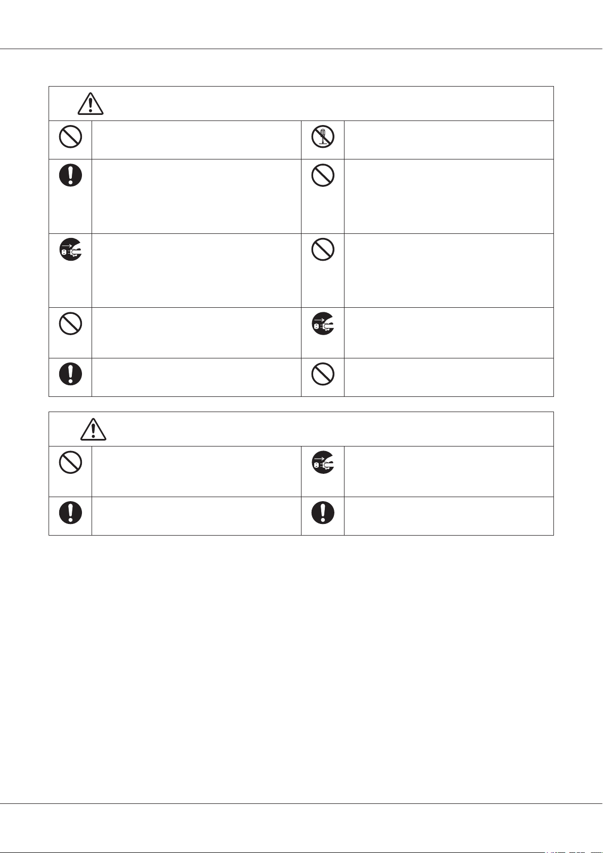
Safety Symbols
The following symbols are used in this manual and on the FD-9 to prevent accidents which may occur as a result of incorrect use of the
instrument.
Denotes an instruction regarding a safety warning or note. Read the instruction carefully to ensure safe and correct use.
Denotes an instruction regarding the risk of electric shock. Read the instruction carefully to ensure safe and correct use.
Denotes an instruction regarding the risk of re. Read the instruction carefully to ensure safe and correct use.
Denotes a prohibited action. This action must never be performed.
Denotes an instruction. This instruction must be strictly adhered to.
Denotes a prohibited action. Never disassemble the instrument.
Denotes an instruction. Be sure to disconnect the AC adapter from the AC outlet.
This symbol indicates A.C.
This symbol indicates D.C.
Notes on this Manual
• Copying or reproduction of all or part of the contents of this manual without KONICA MINOLTA’s permission is strictly prohibited.
• The contents of this manual are subject to change without prior notice.
• Every effort has been made in the preparation of this manual to ensure the accuracy of its contents. However, should you have any
questions or nd any errors, please contact your retailer or a KONICA MINOLTA-authorized service facility.
• KONICA MINOLTA will not accept any responsibility for consequences arising from the use of the instrument.
i
Page 3
Safety Precautions
To ensure correct use of this instrument, read the following points carefully and adhere to them. After you have read this manual, keep it
in a safe place where it can be referred to anytime a question arises.
WARNING
Do not use the instrument in places where ammable or
combustible gases (gasoline, etc.) are present. Doing so
may cause a re.
Always use the AC adapter supplied as a standard
accessory or the optional AC adapter, and connect it to
an AC outlet of the rated voltage and frequency. If an
AC adapter other than those specied by KONICA
MINOLTA is used, it may result in damage to the unit,
re or electric shock.
If the instrument will not be used for a long time,
disconnect the AC adapter plug from the AC outlet.
Accumulated dirt or water on the prongs of the AC
adapter’s plug may cause a re and should be removed.
Do not forcibly bend, twist, or pull the AC adapter
power cable. Do not scratch or alter the power cable or
place heavy objects on it. Doing so may damage the
power cable and cause a re or electric shock.
Insert the power plug fully and securely. Incomplete
inserting may cause re or electric shock.
Failure to adhere to the following points may result in death or serious injury.
Do not disassemble or modify the instrument or the AC
adapter. Doing so may cause a re or electric shock.
Take special care not to allow liquid or metal objects to
enter the instrument. Doing so may cause a re or
electric shock. Should liquid or metal objects enter the
instrument, turn the power off immediately, disconnect
the AC adapter plug from the AC outlet, and contact the
nearest Konica Minolta-authorized service facility.
The instrument should not be operated if it is damaged
or the AC adapter is damaged, or if smoke or odd
smells occur. Doing so may cause a re. In such
situations, turn the power off immediately, disconnect
the AC adapter plug from the AC outlet and contact the
nearest Konica Minolta-authorized service facility.
Always hold the plug itself when disconnecting the AC
adapter plug from the AC outlet. Pulling on the power
cable may damage it and cause a re or electric shock.
Do not insert or disconnect the AC adapter plug from
an AC outlet with wet hands. Doing so may cause
electric shock.
CAUTION
Do not place the instrument on an unstable or sloping
surface. Doing so may result in its falling or
overturning, causing injury. Be careful not to drop the
instrument when carrying it.
Do not open the cover during scanning. If the cover is
opened during scanning, there is a risk that your hand
might get caught in the instrument, resulting in injury.
Failing to adhere to the following points may result in injury or damage to the
instrument or other property.
Make sure that the AC outlet is located near the
instrument and that the AC adapter plug can be
connected to and disconnected from the AC outlet
easily.
When cleaning, disconnect the power plug. Cleaning
with the power plug connected may result in electric
shock.
1
Page 4

Introduction
The Auto Scan Spectrophotometer FD-9 is designed for the rapid automatic scanning of printed materials.
Notes on Use
Be sure to use this instrument properly. Use of this instrument in ways other than those specied in this manual may result in risk of
injury, electric shock, instrument damage, or other problems.
Operating Environment
• Use the FD-9 at an ambient temperature of between 10°C and 35°C and relative humidity of 30 to 85% with no condensation. Do not
use the instrument in areas subject to rapid temperature changes.
• Do not leave the FD-9 in direct sunlight or near sources of heat, such as stoves, etc. The internal temperature of the instrument may
become much higher than the ambient temperature in such cases.
• Do not use the FD-9 in areas where dust, cigarette smoke or chemical gases are present. Doing so may cause deterioration in
performance or a breakdown.
• Do not use the FD-9 near equipment which produces a strong magnetic eld (such as speakers, etc.).
• The FD-9 belongs to installation category I products (equipment which is powered by an AC adapter connected to commercially
available power).
• The FD-9 belongs to pollution degree 2 products (equipment which may cause temporary electrical hazards due to contamination or
condensation or products which are used in such an environment).
• Do not use the FD-9 at altitudes higher than 2,000 m.
• The FD-9 and the AC adapter supplied as a standard accessory have been designed exclusively for indoor use. They should never be
used outdoors because rain or other factors may damage the instrument.
Measurement
• Make sure that test charts are clean and not dusty.
• Be sure that there are no objects blocking the paper entry or paper exit slots of the FD-9.
• The FD-9 is only for measuring paper test charts or similar subjects. It cannot be used for measuring printed cloth or other subjects
with insufcient stiffness.
Power Source
• Make sure that the power switch is set to off (“ “) when the FD-9 is not in use.
• Always use the AC adapter supplied as a standard accessory and connect it to an AC outlet of the rated voltage and frequency.
• Use an AC power supply of the rated supply voltage (within ±10%).
System
• Do not subject the FD-9 to strong impact or vibration. Doing so may cause deterioration of perfor¬mance or breakdown.
• When the FD-9 is not in use, it should be covered to prevent entry of foreign matter.
• The FD-9 may cause interference if used near a television, radio, etc.
• Since the FD-9 uses a microcomputer, external magnetic noise may cause malfunction. In this case, turn the power off, and wait 30
minutes, and then turn it on again.
Notes on Storage
• The FD-9 should be stored at temperatures between 0°C and 40°C, and at a relative humidity of 80% or less (35°C) without
condensation. Do not store the instrument in areas subject to high temperatures, high humidity, sudden changes in temperature, or
where freezing or condensation may occur, because these circumstances may cause a breakdown. It is recommended to store the FD-9
with a drying agent at a temperature around 20°C.
• Do not leave the FD-9 inside a car such as in the trunk. Otherwise, the temperature and/or humidity may exceed the allowable range
for storage during midsummer or midwinter, resulting in a breakdown.
• Keep the packing materials used for shipment and use them to transport the FD-9. This protects the instrument from sudden changes in
temperature, vibration, and shock.
• Do not store the FD-9 in areas where dust, cigarette smoke or chemical gases are present. Doing so may cause deterioration in
2
Page 5

Notes on Use
performance or a breakdown.
• Entry of dust into the instrument will hinder accurate measurement. When the instrument is not in use, please cover the instrument
with the supplied Dust Cover to prevent the entry of dust.
• Be sure to keep all packing materials (cardboard box, cushioning material, plastic bags, etc.). They can be used to protect the
instrument during storage or during transportation to the service facility for maintenance (recalibration, etc.).
Notes on Cleaning
• If the FD-9 becomes dirty, wipe it with a soft, clean dry cloth. Never use solvents such as thinner or benzene.
• If the internal White Calibration Plate becomes dirty, it can be cleaned according to the procedure on p. 30.
• If the FD-9 breaks down, do not try to disassemble and repair it by yourself. Contact a KONICA MINOLTA authorized service facility.
Disposal Method
• Make sure that the FD-9 and its accessories and packing materials are either disposed of or recycled correctly in accordance with local
laws and regulations.
3
Page 6

Table of Contents
Safety Symbols ���������������������������������������������������������������������������������������������������������������������������������������������������������������������������i
Notes on this Manual ����������������������������������������������������������������������������������������������������������������������������������������������������������������� i
Safety Precautions ��������������������������������������������������������������������������������������������������������������������������������������������������������������������� 1
Introduction ������������������������������������������������������������������������������������������������������������������������������������������������������������������������������� 2
Notes on Use ������������������������������������������������������������������������������������������������������������������������������������������������������������������������������� 2
Operating Environment .......................................................................................................................................................................................................... 2
Measurement .......................................................................................................................................................................................................................... 2
Power Source ......................................................................................................................................................................................................................... 2
System .................................................................................................................................................................................................................................... 2
Notes on Storage ....................................................................................................................................................................................................................2
Notes on Cleaning .................................................................................................................................................................................................................. 3
Disposal Method ....................................................................................................................................................................................................................3
Table of Contents ���������������������������������������������������������������������������������������������������������������������������������������������������������������������� 4
Unpacking ���������������������������������������������������������������������������������������������������������������������������������������������������������������������������������� 6
Packing Materials: .................................................................................................................................................................................................................6
Removing Tapes: ................................................................................................................................................................................................................... 6
Standard Accessories ����������������������������������������������������������������������������������������������������������������������������������������������������������������7
Optional Accessories ����������������������������������������������������������������������������������������������������������������������������������������������������������������� 8
System Diagram ������������������������������������������������������������������������������������������������������������������������������������������������������������������������ 9
Names and Functions of Parts ����������������������������������������������������������������������������������������������������������������������������������������������� 10
Preparations ���������������������������������������������������������������������������������������������������������������������������������������������������������������������������� 11
Setting up FD-9 .................................................................................................................................................................................................................... 12
Necessary space ............................................................................................................................................................................................................ 12
Attaching/Removing Paper Guide .......................................................................................................................................................................................13
Attaching ....................................................................................................................................................................................................................... 13
Removing ...................................................................................................................................................................................................................... 13
Attaching/Removing Auto Sheet Feeder FD-A09 (optional accessory) .............................................................................................................................. 14
Attaching ....................................................................................................................................................................................................................... 14
Removing ...................................................................................................................................................................................................................... 15
Connecting the AC adapter ..................................................................................................................................................................................................16
Switching Power On/Off ���������������������������������������������������������������������������������������������������������������������������������������������������������17
Switching power on .............................................................................................................................................................................................................17
Switching power off ............................................................................................................................................................................................................. 17
Connecting FD-9 to Computer����������������������������������������������������������������������������������������������������������������������������������������������� 18
Connecting FD-9 to Computer using USB cable ................................................................................................................................................................. 18
Determining connected USB port number....................................................................................................................................................................19
Setting Network Settings for Connecting FD-9 to Computer via a LAN ............................................................................................................................ 20
Setting network settings directly ..................................................................................................................................................................................20
Setting network settings via DHCP .............................................................................................................................................................................. 22
4
Page 7

Taking measurements ������������������������������������������������������������������������������������������������������������������������������������������������������������� 23
Feeding Test Charts into FD-9 ............................................................................................................................................................................................. 23
Feeding test charts manually ........................................................................................................................................................................................23
Feeding test charts when using optional Auto Sheet Feeder FD-A09 ..........................................................................................................................23
Settings screen ������������������������������������������������������������������������������������������������������������������������������������������������������������������������� 24
Opening/closing settings screen ........................................................................................................................................................................................... 24
Settings screen layout ..........................................................................................................................................................................................................24
Setting items ........................................................................................................................................................................................................................24
Selecting and changing settings ...........................................................................................................................................................................................25
Setting display language ���������������������������������������������������������������������������������������������������������������������������������������������������������26
Troubleshooting ����������������������������������������������������������������������������������������������������������������������������������������������������������������������� 27
Error messages .....................................................................................................................................................................................................................27
Clearing paper jams .............................................................................................................................................................................................................27
When using FD-9 without Auto Sheet Feeder .............................................................................................................................................................. 27
When using FD-9 with Auto Sheet Feeder ...................................................................................................................................................................28
Cleaning ����������������������������������������������������������������������������������������������������������������������������������������������������������������������������������� 30
Cleaning the white calibration plate ....................................................................................................................................................................................30
Cleaning inside the FD-9 ..................................................................................................................................................................................................... 30
Scan Measurement Chart Conditions ����������������������������������������������������������������������������������������������������������������������������������� 32
Specications ��������������������������������������������������������������������������������������������������������������������������������������������������������������������������� 33
5
Page 8
Unpacking
Packing Materials:
Keep all packing materials (cardboard box, cushioning materials, plastic bags, etc.) in a safe place. The FD-9 is a precision measuring
instrument. In the event that the instrument needs to be shipped to a Konica Minolta authorized service facility, the packing materials can
be used to protect the instrument from impact and vibration during shipment. If the original packing materials are lost or damaged, please
contact the nearest Konica Minolta authorized service facility.
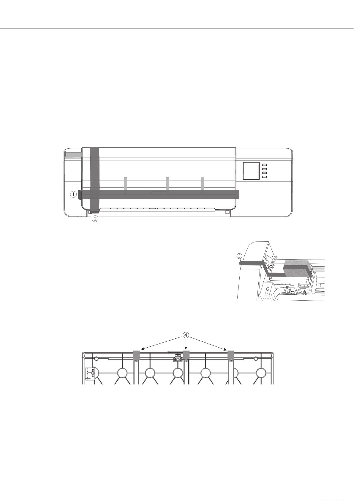
Removing Tapes:
The cover, color measurement sensor unit, and conductive pads of the FD-9 have been taped in position to avoid movement during
shipment. The tapes must be removed before use.
After unpacking the FD-9 and placing it in its nal location, remove the tape strips and as indicated in the illustrations below.
Open the cover and remove tape as shown at right. If power is switched on before tape
is removed, the FD-9 may malfunction. After removing tape , slide the color
measurement sensor unit slightly by hand to check that it moves smoothly. If it does not
move smoothly or if there is excessive noise, please contact your local Konica Minolta
dealer.
Carefully remove the tapes as shown in the gure below. Be careful not to remove the conductive pads under the tapes. If tapes are
not removed, repeatability may suffer.
6
Page 9

Standard Accessories
AC Adapter AC-A324F
Used to supply power from an AC outlet to the instrument.
Input: 100 to 240 V 50/60Hz
Output (Typical): 24 V 6.25A
(STD-24050)
USB Cable (3m) IF-A18
Used to connect the instrument to a computer.
Paper Guide
Used to guide the test chart into the instrument when feeding test charts
manually.
Measurement Utility Software FD-S2w
Used to control the instrument from a computer.
7
Page 10
Optional Accessories
Auto Sheet Feeder FD-A09
Used to automatically feed test charts into the instrument.
Capacity: 100 sheets
8
Page 11
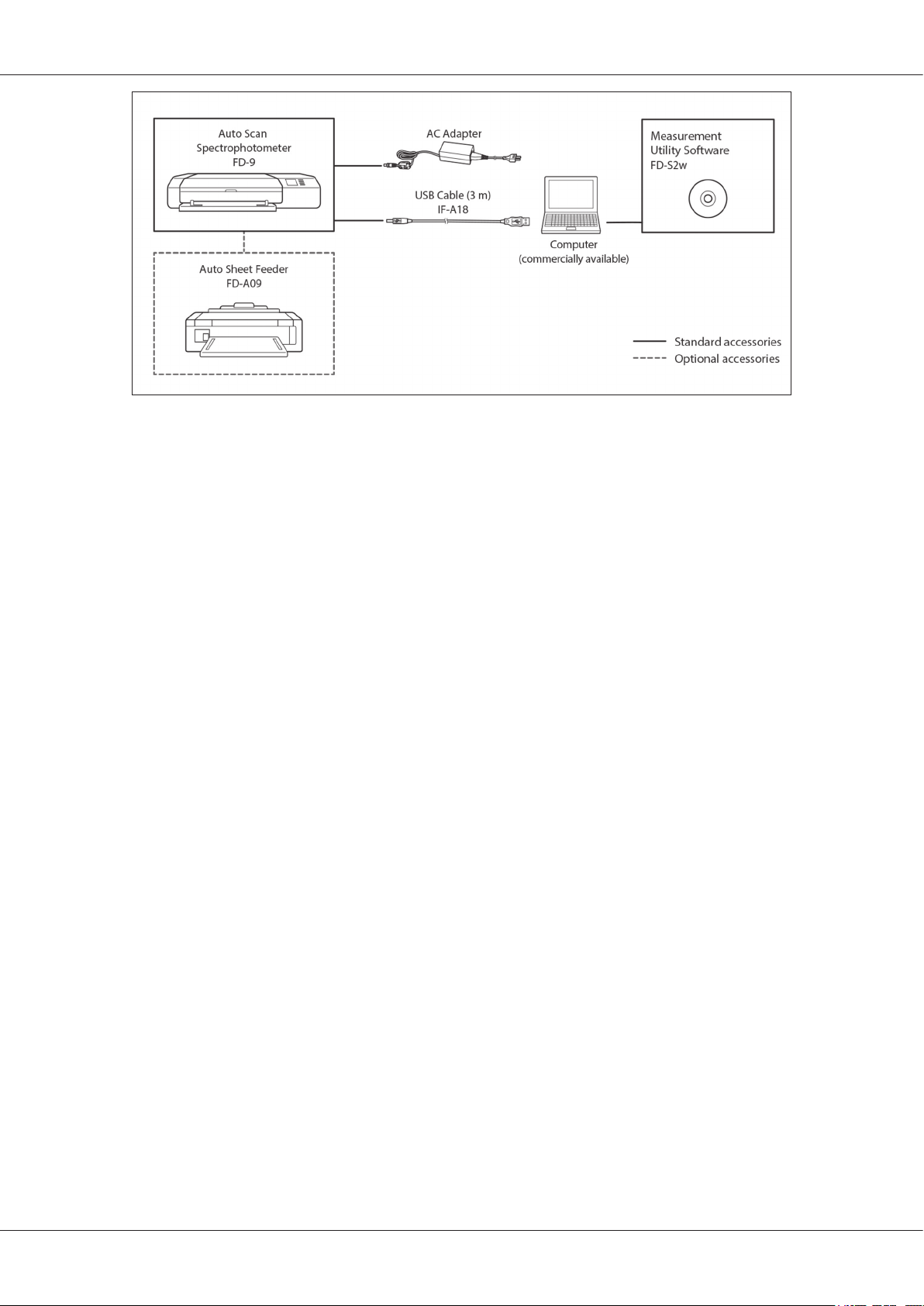
System Diagram
9
Page 12

Names and Functions of Parts
Cover
1
Paper guide mounting slots
2
Display panel
3
Up / down buttons
4
5
6
7
8
9
10
11
12
13
14
15
button
(Return) button
Power button
AC adapter input socket
LAN connection terminal
USB connection terminal
Auto Sheet Feeder alignment holes
Auto Sheet Feeder connector cover
Color measurement sensor unit
Base mounting screws
White calibration plate
For attaching the Paper Guide.
Shows instrument settings, status, error messages, etc.
For selecting items from the setting screen or making numerical settings.
For conrming selection or settings.
For entering the settings screen or returning from the setting screen.
For switching power on and off.
For connecting to the AC adapter
For connecting the instrument to a wired network.
For connecting the instrument to a computer via USB.
Moves back and forth during operation to scan the test chart.
These screws secure the instrument to its base. They can be loosened if necessary to
clear jammed paper (see p. 27) or for cleaning (see p. 30).
• Be sure that these screws are rmly tightened. If they are loose when
measurements are taken, measurement accuracy may suffer.
Used for performing white calibration.
10
Page 13

Preparations
11
Page 14

Preparations
Setting up FD-9
The FD-9 should be set up on a at, level surface with sufcient space for the color chart in front of and behind the FD-9. There should be
enough space in front of the FD-9 for the color chart to be measured to be inserted into and ejected from the FD-9 without any obstacles,
and enough space behind the FD-9 for the color chart to fully extend from the FD-9 without obstacles. (See below.)
• If the FD-9 is set up on a rough surface or a surface which is not level, measurement accuracy may suffer.
• Obstacles may cause the color chart to bend or be shifted to either side, resulting in damage to the color chart or misalignment during
scanning.
• After scanning, the scanned color chart will be ejected from the front of the FD-9. If the FD-9 is placed at the edge of a table, the
ejected color chart might fall to the oor and be damaged.
Necessary space
12
Page 15

Attaching/Removing Paper Guide
Paper Guide is used when test charts will be fed manually into the FD-9.
• If the Auto Sheet Feeder FD-A09 will be used, the Paper Guide should be removed.
• When the Paper Guide is not attached to the FD-9, it should be stored carefully where it will not be lost or broken.
Attaching
While gripping the ends of the Paper Guide, align the
1
hooks of the Paper Guide with the paper guide mounting
slots of the FD-9, and insert the hooks fully.
Slide the Paper Guide straight down until the Paper Guide
2
clicks in place.
• Be careful to slide the Paper Guide straight down. Twisting the Paper Guide or tilting
it away from the FD-9 may cause the hooks to be broken.
Removing
While gripping the ends of the Paper Guide, slide the
1
Paper Guide straight up.
• Be careful to slide the Paper Guide straight up. Twisting the Paper Guide or tilting it
away from the FD-9 may cause the hooks to be broken.
Preparations
Remove the hooks from the paper guide mounting slots.
2
13
Page 16

Preparations
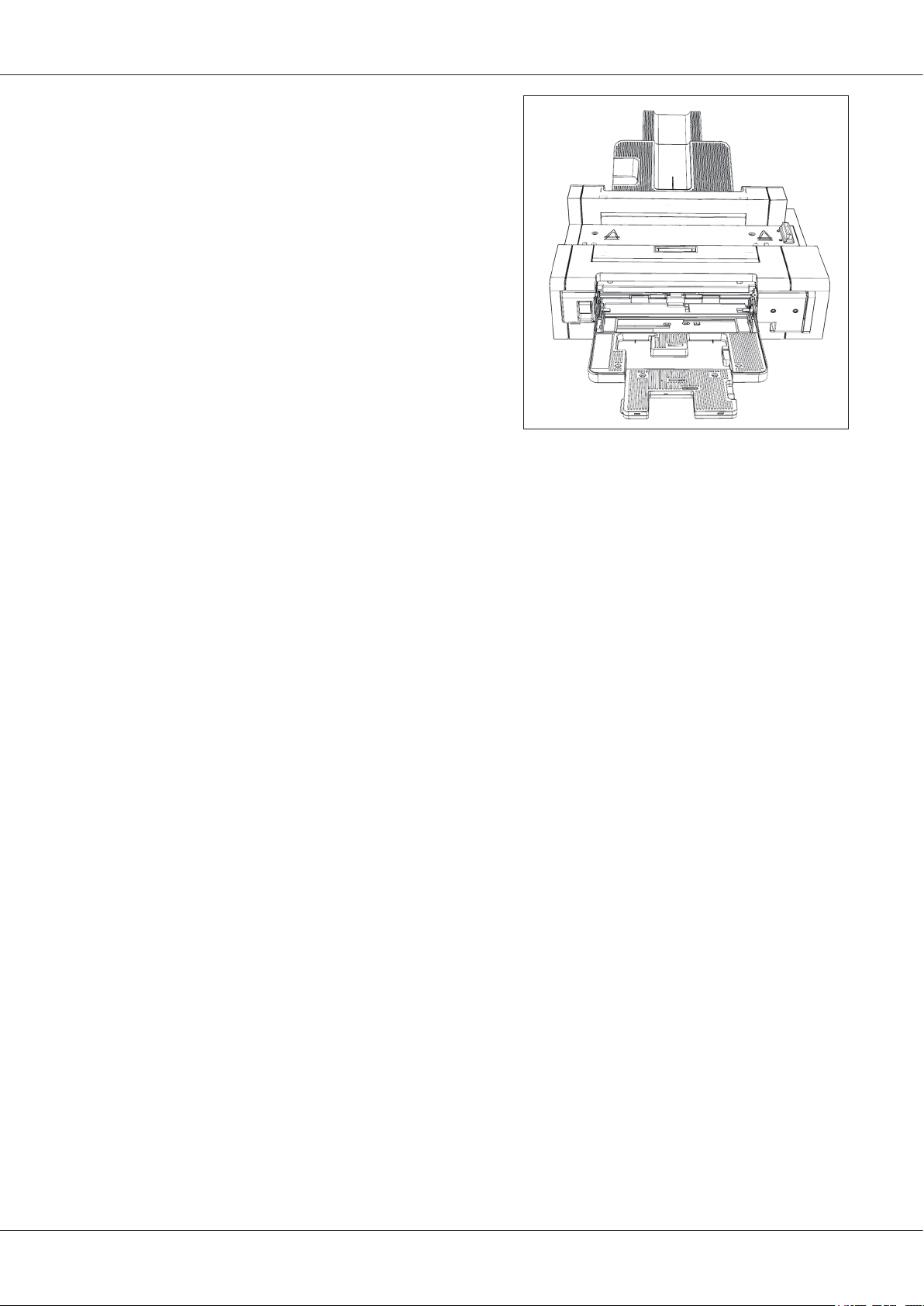
Attaching/Removing Auto Sheet Feeder FD-A09 (optional accessory)
The optional Auto Sheet Feeder FD-A09 can automatically feed a stack of test charts into the FD-9. Up to 100 test charts can be placed in
the Auto Sheet Feeder, and they will be automatically fed into the FD-9 one by one to be scanned.
Attaching
• If the Paper Guide is attached to the FD-9, remove it before proceeding. See p. 13.
Unplug all cords and cables (AC adapter power cord, USB cable, LAN cable) from the FD-9.
1
While holding the cover of the FD-9 closed, tilt the FD-9
2
back so that it rests on its back side.
Push down on the tab of the Auto Sheet Feeder connector
3
cover, pull the cover open, and remove it.
• Please store the cover carefully so that it will not be lost or broken.
Return the FD-9 to the normal upright orientation.
4
Place the Auto Sheet Feeder FD-A09 on a at surface.
5
Lift the FD-9 up, align the Auto Sheet Feeder alignment
6
holes on the bottom of the FD-9 with the alignment pegs
on the Auto Sheet Feeder, and slowly lower the FD-9
straight down onto the Auto Sheet Feeder until it clicks in
place.
14
Page 17

Removing
Switch off the power of the FD-9.
1
Unplug all cords and cables (AC adapter power cord, USB
2
cable, LAN cable) from the FD-9.
Lift the FD-9 straight up off of the Auto Sheet Feeder.
3
Replace the Auto Sheet Feeder connector cover on the
4
FD-9.
Preparations
15
Page 18

Preparations
Connecting the AC adapter
Warning
• Always use the AC adapter supplied as a standard accessory or a specied replacement AC adapter, and use the AC adapter only with
an AC outlet of the rated voltage and frequency. Failure to do so may damage the FD-9 or AC adapter, or may cause electric shock or
re.
• If the FD-9 will not be used for a long period of time, disconnect the AC adapter from the AC outlet.
• When plugging the AC adapter into an AC outlet, be sure that the prongs of the plug are clean and dry. Accumulated dirt or moisture
on the prongs of the plug may cause a re and should be removed.
• When plugging in or unplugging a cord, be sure to hold the plug, not the cord. Do not pull on or forcibly bend the cord. Doing so may
result in broken wires.
• Do not plug in or unplug the AC adapter with wet hands. Doing so may cause electric shock.
• Be sure to insert plugs fully and securely. Incomplete insertion may cause re or electric shock.
• Do not disassemble or modify the AC adapter or cords. Doing so may cause re or electric shock.
• Do not unplug or plug in the AC adapter with the instrument’s power set to “ON” ( | ) Doing so may cause a malfunction.
Procedure
Make sure that the power switch of the FD-9 is set to off
1
().
Insert the output plug of the AC adapter power cord into
2
the power cord inlet of the AC adapter as shown.
Insert the output plug of the AC adapter into the AC
3
adapter inlet of the FD-9 as shown. Be sure the plug is
oriented correctly.
Insert the input plug of the AC adapter power cord into an
4
AC wall outlet.
• When disconnecting the AC adapter, make sure that the power switch is set to off
().
16
Page 19

Switching Power On/Off
Switching power on
Slide the power switch to on ( | ). The FD-9 will start up.
1
The Konica Minolta logo will be displayed for a few seconds, followed by the initialization display. When initialization has been
completed (after about 25 seconds), the “Please connect” display will be shown.
Switching power off
Slide the power switch to off ().
1
17
Page 20

Connecting FD-9 to Computer
The FD-9 can be connected to the computer directly using a USB cable or via a LAN.
When connecting via a LAN, either DHCP or a xed IP address can be used.
Connecting FD-9 to Computer using USB cable
• Use the included USB Cable IF-A18 (3m) to connect the FD-9 and computer.
• It is recommended that the software to connect to and control the instrument (such as the included Measurement Utility Software
FD-S2w) be installed prior to connecting the FD-9.
• The USB communication port of the instrument conforms to USB 2.0.
• When connecting the instrument and computer, the USB driver for the instrument needs to be installed. If it is not installed with the
software, you will be prompted to install the driver when the instrument is rst connected to the computer and switched on.
• The instrument is not designed to be powered via the USB cable. The AC adapter must be used.
• Make sure that the USB connector plugs are properly oriented and connected securely. Check the shapes of the receptacle and plug,
and insert the plug fully into the receptacle.
• When connecting/disconnecting the USB cable, always hold onto the connector plug. Do not pull on or forcibly bend the cable. Doing
so may result in wire breakage.
• Make sure that the cable has sufcient length. Putting tension on the cable may cause connection failure or wire breakage.
In general, a USB cable can be connected/disconnected while the instrument and computer are switched on, but in the procedure below
the FD-9 and computer are switched off.
Plug the USB Type B plug of the USB Cable into the USB
1
connection terminal on the back of the FD-9.
Plug the USB Type A plug of the USB Cable into the USB
2
port of the computer.
Connect the AC adapter and switch on the FD-9 and
3
computer.
• When you are prompted to install the USB driver, specify the USB driver included
with the software or on the Measurement Utility Software FD-S2w disk.
• When using the included Measurement Utility Software FD-S2w, refer to the
FD-S2w Installation Guide.
18
Page 21

Determining connected USB port number
The number of the USB port assigned to the FD-9 is required when connecting to the FD-9 via USB.
To see which port has been assigned, follow the steps below.
On Windows 7:
Open Control Panel.
1
Select System and Security.
2
In System, click Device Manager.
3
Click on the next to Ports (COM & LPT). The list of connected devices will appear.
4
“Measuring Instruments” will appear in the list, followed by the assigned COM port in parentheses.
5
On Windows 8, Windows 8�1, or Windows 10:
Point to the lower-left corner of the screen and then right-click in the window that appears.
1
In the menu that appears, click “Device Manager” to open the Device Manager.
2
Connecting FD-9 to Computer
Click “Ports (COM & LPT)” to expand it, and check the COM port assigned to “Measuring Instruments”.
3
On Mac OS X:
Press and hold the Option key on your keyboard, and click the Apple menu.
1
Choose “System Information” or “System Proler”.
2
In the window that appears, select “USB” from the left column and check the COM port assigned to “Measuring
3
Instruments”.
19
Page 22

Connecting FD-9 to Computer
Setting Network Settings for Connecting FD-9 to Computer via a LAN
The FD-9 can be connected to a LAN and shared by multiple computers. When connecting the FD-9 to a LAN, network settings can be
performed directly or DHCP (Dynamic Host Conguration Protocol) can be used.
• Network settings can also be performed from Measurement Utility Software FD-S2w when the FD-9 is connected via USB.
Setting network settings directly
The IP address, subnet mask, and default gateway can be set directly in the settings screen.
• It is not possible to set the network name directly using the FD-9 buttons.
Press to open the settings screen.
1
Press or repeatedly to select “IP address” and press .
2
The rst number of the IP address will be highlighted.
• “IP address” will be disabled if “DHCP” is set to “ON”. To change the setting to “OFF”, see p. 22.
Press or repeatedly to set the desired value for the rst
3
number.
• Holding or pressed will cause the value to change continually.
• Values between 0 and 255 can be set. If or is pressed again when the lowest or highest value
has been reached, the number will change to the highest or lowest value.
Press to move to the next number.
4
Repeat steps 3 and 4 until all numbers have been set for the IP
5
address.
Press to select “Subnet mask” and press . The rst number of
6
the subnet mask will be highlighted.
Press or repeatedly to set the desired value for the rst
7
number.
• Holding or pressed will cause the value to change continually.
• Values between 0 and 255 can be set. If or is pressed again when the lowest or highest value
has been reached, the number will change to the highest or lowest value.
Press to move to the next number.
8
Repeat steps 3 and 4 until all numbers have been set for the subnet
9
mask.
20
Page 23

Connecting FD-9 to Computer
Press to select “Default gateway” and press . The rst number of the default gateway will be
10
highlighted.
Press or repeatedly to set the desired value for the rst number.
11
• Holding or pressed will cause the value to change continually.
• Values between 0 and 255 can be set. If or is pressed again when the lowest or highest value has been reached, the number will change to the highest or
lowest value.
Press to move to the next number.
12
Repeat steps 3 and 4 until all numbers have been set for the default
13
gateway.
Press to select “SAVE DATA” and press . The message
14
“Caution: It reboots after saving setting data” will be shown.
Press to save the settings and reboot the FD-9.
15
Once these values have been set, connection to the FD-9 from within the same subnet can
be performed by specifying the IP address during connection.
21
Page 24

Connecting FD-9 to Computer
Setting network settings via DHCP
If your network has DHCP enabled, you can set DHCP on the FD-9 to “ON” and allow your system to automatically allot the IP address,
subnet mask, and default gateway.
Changing the DHCP setting
Press to open the settings screen.
1
Press or repeatedly to select “DHCP” and press .
2
Press or to change the setting to the desired setting.
3
ON: Network settings are performed automatically via DHCP.
OFF: Network settings are not performed automatically.
Press to select “SAVE DATA” and press . The message
4
“Caution: It reboots after saving setting data” will be shown.
Press to save the settings and reboot the FD-9.
5
22
Page 25

Taking measurements
Measurements with the FD-9 are controlled from software, such as the included Measurement Utility Software FD-S2w. For details on
taking measurements, please refer to the instruction manual for the software that you are using.
Feeding Test Charts into FD-9
• If the base mounting screws inside the cover are loose when measurements are taken, measurement accuracy may suffer. Be sure that
the screws are rmly tightened.
• If the test chart is curled or creased, it may result in a paper jam. Please measure only test charts without creases or excessive curl.
Permissible curl amount:
Feeding test charts manually
• For information on feeding test charts when using the optional Auto Sheet Feeder FD-A09, please see below.
Place the end of the test chart on the Paper Guide, and
1
slide the paper guides so that they are positioned
touching the sides of the test chart as shown.
Slide the test chart gently between the guides and into the FD-9.
2
When the test chart enters the FD-9 by a certain amount, it will
be automatically pulled into the FD-9 for measurements. When
the FD-9 starts pulling the test chart in, let go of the test chart.
• Be sure to slide the test chart in straight. If the paper guide positions are too narrow
or if the test chart goes in at an angle, the test chart may ride up onto the paper
guides, which may cause measurement accuracy to suffer.
Feeding test charts when using optional Auto Sheet Feeder FD-A09
When using the Auto Sheet Feeder, place the test charts
1
in the supply tray and slide the paper guides so that they
are positioned touching the sides of the test charts as
shown.
• The supply tray can hold up to 100 sheets of paper.
Feeding of the test charts from the supply tray into the FD-9 is controlled by the software. For details, please refer to the software
instruction manual.
23
Page 26

Settings screen
The settings screen shows instrument information, error messages, etc. and enables setting of some instrument settings.
Opening/closing settings screen
If the settings screen is not shown, press to open the settings screen.
When the settings screen is shown, press to close the settings screen and cancel any incomplete settings.
Settings screen layout
The settings screen is divided into 4 main parts.
Selection area for selecting the item to view or set.
Value/setting area for displaying the value and changing the setting of the selected item.
Message area for showing messages related to operation of the display panel.
Key function description area describing the functions of the keys in the current operation.
Setting items
Serial No. The serial number of the instrument. Not changeable.
Firmware version The version of the FD-9 rmware. Not changeable.
MAC address The MAC address of the FD-9’s network interface board. Not changeable.
Network name The network name assigned to the FD-9. It can be set or changed from within the software. For details, refer to
the software instruction manual.
Display language
(See p. 26.)
DHCP
(See p. 22.)
IP address
(See p. 20.)
Subnet mask
(See p. 20.)
Default gateway
(See p. 20.)
SAVE DATA Saves changes to network settings (DHCP, IP address, subnet mask, and default gateway), and reboots the
English
Japanese
Chinese (Simplied)
• Change is applied immediately after
ON: The network settings are automatically assigned using DHCP
off: Use of DHCP is disabled
IP address (xxx.xxx.xxx.xxx) set on FD-9. It can be set using the
software when FD-9 is connected.
• Disabled if DHCP is set to “ON”
• Changes made using the buttons are not applied until SAVE DATA is performed.
Subnet mask (xxx.xxx.xxx.xxx) set on FD-9. It can be set using the
software when FD-9 is connected.
• Disabled if DHCP is set to “ON”
• Changes made using the buttons are not applied until SAVE DATA is performed.
Default gateway (xxx.xxx.xxx.xxx) set on FD-9. It can be set using the
software when FD-9 is connected.
• Disabled if DHCP is set to “ON”
• Changes made using the buttons are not applied until SAVE DATA is performed.
FD-9 to apply the new settings.
is pressed.
, , and buttons or from
, , and buttons or from
, , and buttons or from
24
Page 27

Settings screen
Selecting and changing settings
Press or to move the cursor to the desired item. The value or current setting of the selected item will appear in the value/setting
area.
To change the selected item, refer to the page specied for that item in the table above.
• Setting items which are shown in gray in the settings screen cannot be changed.
25
Page 28

Setting display language
The language shown on the display panel can be selected according to the following procedure.
Press to open the settings screen.
1
Press or repeatedly to select “Display language” and press
2
3
4
. A list of the language selections will appear, with the current
setting highlighted.
Press or repeatedly to select the desired language.
Press to conrm the selection. The display screen will change
immediately to the selected language.
26
Page 29

Troubleshooting
Error messages
The messages below may be displayed when using the instrument. When one of these messages appears, please take the action indicated
below. If the message continues to appear even after taking the recommended action, contact the nearest KONICA MINOLTA authorized
service facility.
Error message Possible cause/problem Action
Paper jammed Paper has jammed in the FD-9. Follow the procedure below to clear the paper jam.
Paper has jammed in the Auto Sheet Feeder. Follow the procedure on p. 28 to clear the paper jam.
Cover opened Cover of FD-9 is open. Close the cover and wait until FD-9 initialization is complete.
Fatal Error
Error code: ********
Warning code: ********
Clearing paper jams
If the paper becomes jammed during measurement, follow the procedures below to remove the jammed paper.
When using FD-9 without Auto Sheet Feeder
A fatal error has occurred. Switch off the FD-9, wait 30 seconds, and then switch it back
on. If the error continues to occur, note the Error code and
Warning code numbers, and contact the nearest KONICA
MINOLTA authorized service facility
When using the FD-9 without the Auto Sheet Feeder, the location of paper jams is usually where the paper is fed between the base and the
scan mechanism.
Press to eject the paper. If the paper cannot be
1
ejected by the FD-9, continue with the steps below to
manually clear the paper jam.
Switch off the FD-9.
2
Disconnect all cables (USB cable, LAN cable, AC adapter
3
cable).
Open the cover.
4
Loosen the two screws as shown completely so that they
5
are free of the base.
Close the cover.
6
Grasp the ends of the FD-9 and tilt the FD-9 body
7
backward as shown. The base should stay at.
Remove the jammed paper.
8
27
Page 30

Troubleshooting
Grasp the ends of the FD-9 and tilt the FD-9 body onto the
9
base again.
Open the cover
10
Tighten the two screws as shown until snug.
11
• If the screws are loose when measurements are taken, measurement accuracy may
suffer.
• Do not overtighten.
Close the cover.
12
Reconnect the cables and switch the FD-9 back on.
13
When using FD-9 with Auto Sheet Feeder
When using the FD-9 with the Auto Sheet Feeder, the location of paper jams is usually in one of the following locations: Where the paper
feeds from the supply tray into the Auto Sheet Feeder and then into the FD-9, within the FD-9, or where the paper feeds from the FD-9
through the Auto Sheet Feeder into the exit tray. To clear paper jams, check each section.
Switch off the FD-9.
1
Disconnect all cables (USB cable, LAN cable, AC adapter
2
cable).
Remove the FD-9 from the Auto Sheet Feeder.
3
• If the paper jam is inside the FD-9, follow the procedure in the preceding section
“When using FD-9 without Auto Sheet Feeder” to remove the jammed paper.
If paper is still jammed, lift the lever on the left side of the
4
supply tray and swing the supply tray mechanism out to
the right.
28
Remove any paper from inside the Auto Sheet Feeder.
5
Page 31

Pull the handle on the inside cover to open the inside
6
panel and check that there is no paper inside the panel. If
there is paper there, remove it.
Pull up on the handle to open the top cover and check
7
that there is no paper inside the panel. If there is paper
there, remove it.
Close the top cover and inner cover, and then swing the
8
supply tray mechanism closed again.
Troubleshooting
If there is paper jammed on the exit tray side, remove it.
9
Replace the FD-9 in the Auto Sheet Feeder, connect all
10
cables again, and switch the FD-9 back on.
29
Page 32

Cleaning
Cleaning the white calibration plate
If the white calibration plate becomes dirty, it will affect measurement accuracy. If the white calibration plate becomes dirty, it should be
cleaned as described below.
Make sure that the FD-9 is switched off.
1
Disconnect all cables (USB cable, LAN cable, AC adapter cable).
2
Open the cover.
3
Loosen the two screws as shown completely so that they
4
are free of the base.
Close the cover.
5
Grasp the ends of the FD-9 and tilt the FD-9 body
6
backward as shown. The base should stay at.
Wipe the surface of the white calibration plate with a
7
clean, dry, soft, lint-free cloth or lens-cleaning tissue.
• If the white calibration plate is stained, lens-cleaning uid may be used to try to
remove the stain.
• Never use benzene or other solvents to clean the white calibration plate. Doing so
may cause discoloration or damage to the plate.
• If a stain cannot be removed, contact the nearest Konica Minolta service facility.
Grasp the ends of the FD-9 and tilt the FD-9 body onto the
8
base again.
Open the cover
9
Tighten the two screws as shown until snug.
10
• If the screws are loose when measurements are taken, measurement accuracy may
suffer.
• Do not overtighten.
Close the cover and reconnect cables.
11
Cleaning inside the FD-9
If paper dust, etc. accumulates inside the FD-9, it may cause paper jams or problems with patch recognition. If paper jams or patch
recognition problems start to occur more frequently, the inside of the FD-9 should be cleaned according to the procedure below.
30
Page 33

Make sure that the FD-9 is switched off.
1
Disconnect all cables (USB cable, LAN cable, AC adapter cable).
2
Open the cover.
3
Loosen the two screws as shown completely so that they
4
are free of the base.
Close the cover.
5
Grasp the ends of the FD-9 and tilt the FD-9 body
6
backward as shown. The base should stay at.
Cleaning
Clean the cover glass of the line sensor and the white
7
backing and other plastic surfaces with a clean, dry, soft,
lint-free cloth.
Wipe off the rubber rollers with alcohol to clean and
8
condition them.
Grasp the ends of the FD-9 and tilt the FD-9 body onto the
9
base again.
Open the cover
10
Tighten the two screws as shown until snug.
11
• If the screws are loose when measurements are taken, measurement accuracy may
suffer.
• Do not overtighten.
Close the cover and reconnect cables.
12
31
Page 34

Scan Measurement Chart Conditions
The FD-9 can scan charts conforming to the following conditions:
Paper width 45 to 330 mm
Paper length 170 to 660 mm
Paper thickness 0.05 to 0.45 mm
Minimum patch size: 6 x 6 mm
Maximum number of patches per page A4-size paper: 1394
A3-size paper: 2928
• Positioning markers are not necessary.
The layout of the chart on the paper must conform to the following layout. (See below.)
Minimum leading margin 23 mm
Minimum tailing margin 33 mm
Minimum side margins 4 mm
Horizontal shift Within 150 mm of paper center line
32
\
Page 35

Specications
Model FD-9
Illumination/ viewing system 45°a:0° (annular illumination) *
Conforms to CIE No. 15, ISO 7724/1, DIN5033 Teil 7, ASTM E 1164, and JIS Z 8722 Condition a
for reectance measurements.
Spectral separation device Concave grating
Wavelength range 380 to 730 nm
Wavelength pitch 10 nm
Half bandwidth Approx. 10 nm
Measurement area Approx. Ø3 mm
Measurement light source LED
Measurement range Reectance: 0 to 150%
Short-term repeatability Colorimetric: Within σΔE00 0.05
(Under Konica Minolta test conditions where a white calibration plate is measured 30 times at
10-second intervals after white calibration has been performed.)
Inter-instrument agreement Within ΔE00 0.3
(Average of 12 BCRA Series II color tiles compared to values measured with a master body under
Konica Minolta standard conditions.)
Measurement time Approx. 4 min. for 1500 patches
(According to Konica Minolta standard conditions)*
Measureable charts Paper width 45 to 330 mm
Paper length 170 to 660 mm
Paper thickness 0.05 to 0.45 mm
Minimum patch size 6 × 6 mm
Maximum number of patches per sheet of paper A4-sized paper: 1394
Output item Spectral reectance
Illumination conditions *
Backing condition White backing, compliant with ISO 13655
Interface USB2.0; 100Base-TX
Power Dedicated AC adapter: Input: AC 100 to 240 V 50/60 Hz
Dimensions
(W × D × H)
Weight Main body only: Approx. 10.5 kg
Operating temperature/ humidity range 10 to 35°C, 30 to 85% relative humidity with no condensation
Storage temperature/ humidity range 0 to 45°C, 0 to 85% relative humidity with no condensation
Standard accessories AC adapter, USB cable, Measurement Utility Software FD-S2w, Paper Guide
Optional accessories Auto Sheet Feeder FD-A09
2
M0 (A), M1 (D50), M2 (A+UV lter), C, ID50, D65, ID65, F2, F6, F7, F8, F9, F10, F11, F12,
User-dened illuminant
Output: DC 24 V 5 A
Main body only: 716 × 251 × 159 mm
Auto Sheet Feeder FD-A09 (optional accessory) only: 601 × 1158 (with trays extended) × 245 mm
*1 Illumination for wavelengths below 400 nm is unidirectional.
*2 M0, M1, and M2 illumination conditions conform to the illumination conditions in ISO 13655 Section 4.2.2 Illumination
requirements and measurement conditions.
*3 Paper size: A3; Patch size: 6 × 6 mm; Patch distribution: 47 rows × 32 columns
1
3
A3-sized paper: 2928
33
Page 36

9222-A8AN-11 ©2015KONICAMINOLTA,INC. BFMBGA PrintedinJapan
 Loading...