

Page 1

T
User Manual
Di850
www.minoltaeurope.com
he essentials of imaging
Page 2

Table of Contents
1 Introduction
1.1 We Want You to Be a Satisfied Customer ..................................1-1
1.2 Protecting the Environment. . . ....................................................1-2
Takeback and Reutilization.............................................................1-2
What is Energy Star®? ...................................................................1-2
Use of Recycled Paper ...................................................................1-2
1.3 Guide to this Manual.....................................................................1-3
How is this Manual Structured? ...................................................... 1-3
A Brief Explanation of the Conventions
Used in this Manual.........................................................................1-4
A Brief Explanation of Important Concepts
and Symbols ...................................................................................1-5
1.4 Overview of System Features ......................................................1-8
General Features............................................................................1-8
Automatic Features .......................................................................1-12
Finishing Features......................................................................... 1-13
Features that can only be Set Up by a
Service Technician........................................................................ 1-14
WWW-Server Function ................................................................. 1-15
2 Getting to Know Your System
2.1 System Overview ..........................................................................2-1
External System Overview ..............................................................2-1
Internal System Overview ...............................................................2-3
2.2 Options (Accessories)..................................................................2-4
Finisher FN-115/FN-7 .....................................................................2-4
Cover Inserter C for Finisher...........................................................2-7
Large Capacity Cassette (LCC) C-403N/C-404N ........................... 2-8
TMG-2 Trimming Unit (optional for FN-7 Finisher)..........................2-9
PK-3 Hole Punch Unit ................................................................... 2-11
ZK-2 Punch/Z-fold Unit.................................................................. 2-12
Memory Expansions...................................................................... 2-13
Pi8500 Printcontroller....................................................................2-13
Di850 IVZ-1
Page 3

2.3 Safe Working with Your System ............................................... 2-14
Laser Safety ................................................................................. 2-18
Internal Laser Radiation ............................................................... 2-18
Safety Label.................................................................................. 2-20
System serial number ................................................................... 2-22
2.4 Transporting the System ........................................................... 2-23
2.5 Installing the System.................................................................. 2-23
Environmental Requirements ....................................................... 2-23
Installation Site ............................................................................. 2-23
Space required for System ........................................................... 2-24
Storing Supplies ........................................................................... 2-25
2.6 Connecting the System.............................................................. 2-25
Voltage and Frequency Tolerances.............................................. 2-25
2.7 Switching the System on and off .............................................. 2-26
Switching the System on .............................................................. 2-26
Switching the System off .............................................................. 2-27
2.8 Control Panel Keys and Indicators........................................... 2-28
Control Panel................................................................................ 2-28
Indicators and Keys on the Touch Screen.................................... 2-30
2.9 Using the Touch Screen ............................................................ 2-33
2.10 Adding Paper .............................................................................. 2-34
Refilling Trays 1, 2 and 3.............................................................. 2-35
Adding Paper to Paper Tray 4 - C-403N (optional) ..................... 2-37
Adding Paper to Paper Tray 4 - C-404N (optional) ..................... 2-39
Filling the Bypass Tray ................................................................. 2-41
2.11 Adding Toner .............................................................................. 2-43
2.12 Replenishing the Staple Supply................................................ 2-46
Adding Staples for the FN-115 Finisher (optional) ....................... 2-46
Adding Staples for the FN-7 Finisher (optional) ........................... 2-49
2.13 Monitoring the PM Count Time ................................................. 2-52
Viewing the PM Count .................................................................. 2-52
Printing the PM Count .................................................................. 2-53
Closing the PM Count Screen ...................................................... 2-53
2.14 Shutting Down the System ........................................................ 2-54
2.15 Please Observe these Precautions........................................... 2-55
. . . when working with your system.............................................. 2-55
. . . when servicing and repairing the system ............................... 2-55
2.16 Proper Use of Your System ....................................................... 2-56
IVZ-2 Di850
Page 4

3 Initial Steps . . .
3.1 Basic Operator Steps....................................................................3-1
Entering the Number of Copies....................................................... 3-1
Start Cycle....................................................................................... 3-2
Stop Cycle....................................................................................... 3-2
Reset System Settings ....................................................................3-2
3.2 Activating the System...................................................................3-3
Ending Energy Saving Mode...........................................................3-3
Ending Auto Shut Off ...................................................................... 3-3
Interrupting Weekly Timer Mode ..................................................... 3-4
Entering the E.K.C. Password.........................................................3-6
3.3 Placing the Originals on the Original Glass ............................... 3-8
3.4 Feeding Originals Using the EDH.............................................. 3-10
Loading Equal-Sized Originals into the EDH ................................3-11
Loading Single Originals into the EDH (SDF) ...............................3-12
Loading Mixed-Sized Originals into the EDH ................................3-13
Place Z-Folded Originals in the EDH ............................................3-14
3.5 Checking the System Settings...................................................3-15
Changing Settings.........................................................................3-15
Releasing Settings ........................................................................3-17
Processing a Proof Copy ..............................................................3-18
3.6 Reserving Copy Jobs .................................................................3-19
Setting up Reserve Jobs ............................................................... 3-20
Calling up the Status Display ........................................................ 3-21
Status Display Message Definitions.............................................. 3-22
Changing the Order of Reserve Jobs............................................3-23
Deleting a Reserve Job ................................................................. 3-24
Checking the User Name of a Reserve Job..................................3-25
Calling up the List of Already Executed Jobs ................................ 3-26
Opening the Noncomplete Job List...............................................3-27
Interrupting the Setup of a Reserve Job ....................................... 3-28
3.7 Interrupting a Copy Job..............................................................3-30
3.8 Recalling System Settings of the Last Job...............................3-33
3.9 Saving and Recalling System Settings .....................................3-34
Saving System Settings ................................................................ 3-34
Recalling System Settings ............................................................3-37
3.10 Check System Meter Count........................................................3-39
Viewing the Meter Counts.............................................................3-39
Printing the Counter List................................................................3-40
Di850 IVZ-3
Page 5

3.11 Enabling Energy Saving Modes ................................................ 3-41
Enabling Energy Saving Mode ..................................................... 3-42
Enabling Auto Shut Off Mode ....................................................... 3-43
3.12 Using the Bypass Tray............................................................... 3-44
Load the Paper on to the Bypass Tray......................................... 3-44
Processing Tab Papers ................................................................ 3-45
3.13 Using the Help Mode .................................................................. 3-46
Open Help Topic Overview........................................................... 3-47
Call Help for a Specific Cycle ....................................................... 3-48
3.14 Using Bookmark Function......................................................... 3-49
4 Basic Functions
4.1 Setting the Output Mode .............................................................. 4-1
Non Sort – Output to the Main Tray................................................ 4-3
Sort – Output to the Main Tray ....................................................... 4-4
Staple – Output to the Main Tray.................................................... 4-6
Group – Output to the Main Tray.................................................... 4-9
Output to the Sub Tray ................................................................. 4-11
Folding, Stapling & Folding and Trimming.................................... 4-14
Adding Front and Back Cover Sheets .......................................... 4-19
Hole-Punch ................................................................................... 4-22
Z-Fold ........................................................................................... 4-25
Manual Stapling, Punching or Folding.......................................... 4-28
Output without Finisher................................................................. 4-31
Using two Systems in Tandem..................................................... 4-35
4.2 Setting the Copy Mode............................................................... 4-40
Creating 1 and 2-sided Copies (Using the EDH).......................... 4-41
Creating 2-sided Copies (Using the Original Glass)..................... 4-43
4.3 Adjusting the Contrast ............................................................... 4-46
Enabling Auto Exposure Mode ..................................................... 4-47
Manually Adjusting Copy Density................................................. 4-48
Adjusting the Image Density......................................................... 4-49
4.4 Setting the Zoom Ratio .............................................................. 4-51
Enabling Automatic Magnification Selection (AMS) ..................... 4-52
Selecting a Preset Zoom Ratio..................................................... 4-54
Selecting User-set Zoom Ratios ................................................... 4-55
Horizontal/Vertical Stretch ............................................................ 4-56
IVZ-4 Di850
Page 6

4.5 Setting the Copy Paper Size ......................................................4-57
Enabling Auto Paper Select Mode (APS)......................................4-58
Manually Selecting a Paper Tray ..................................................4-60
Specifying the Paper Type/Size for the Bypass Tray....................4-61
Specify Copy Start on Wide Size Paper
for the Bypass Tray ....................................................................... 4-63
4.6 Applying Functions.....................................................................4-65
Storing Originals (from the Original Glass) ................................... 4-66
Storing Originals (from EDH) ........................................................ 4-68
Using Rotation Mode.....................................................................4-70
Set Original Position (Special Originals) ....................................... 4-74
Setting Text/Photo Enhance (Special Originals) ...........................4-76
Copying Mixed Sizes (Special Originals) ...................................... 4-78
Copying Z-Folded Originals (Special Originals)............................4-80
Feeding Originals Individually – SDF
(Special Originals)......................................................................... 4-82
Defining Special Original Types (Special Originals)...................... 4-86
5 Applications
5.1 Adding Inserts and Cover Sheets................................................ 5-2
Information on: Inserts and Cover Sheets.......................................5-3
Procedure: Adding Inserts and Cover Sheets.................................5-4
5.2 Executing Chapter Mode..............................................................5-6
Information on: Chapter Mode ........................................................5-6
Procedure: Executing Chapter Mode..............................................5-7
5.3 Creating Combinations................................................................. 5-9
Information on: Combination .........................................................5-10
Procedure: Creating Combinations...............................................5-11
5.4 Creating Booklets .......................................................................5-13
Information on: Booklets ...............................................................5-14
Procedure: Creating Booklets.......................................................5-15
5.5 Creating OHP Interleave ............................................................. 5-17
Information on: OHP Interleave..................................................... 5-17
Procedure: Creating OHP Interleave ............................................5-18
5.6 Inserting Images..........................................................................5-20
Information on: Inserting Images...................................................5-20
Procedure: Inserting Images.........................................................5-21
5.7 Processing Dual Page Originals................................................5-23
Information on: Dual Page ............................................................5-24
Procedure: Processing Dual Page Originals.................................5-25
Di850 IVZ-5
Page 7

5.8 Program Job ............................................................................... 5-27
Information on: Program Job ........................................................ 5-27
Procedure: Program Job .............................................................. 5-28
5.9 Using Non-Image Area Erase .................................................... 5-30
Information on: Non-Image Area .................................................. 5-31
Procedure: Using Non-Image Area Erase.................................... 5-32
5.10 Creating Reverse Images........................................................... 5-33
Information on: Reverse Image .................................................... 5-33
Procedure: Creating Reverse Images .......................................... 5-34
5.11 Using Image Repeat Mode......................................................... 5-35
Information on: Repeat................................................................. 5-36
Procedure: Using Image Repeat Mode ........................................ 5-38
5.12 Using Frame/Fold Erasure......................................................... 5-40
Information on: Frame/Fold Erasure............................................. 5-40
Procedure: Using Frame/Fold Erasure......................................... 5-41
5.13 Using Auto Layout...................................................................... 5-43
Information on: Auto Layout ......................................................... 5-43
Procedure: Using Auto Layout...................................................... 5-44
5.14 Using Full-Image Area................................................................ 5-45
Information on: Full-Image Area ................................................... 5-45
Procedure: Using Full-Image Area ............................................... 5-46
5.15 Creating a File Margin ................................................................ 5-47
Information on: Image Shift .......................................................... 5-48
Procedure: Creating a File Margin................................................ 5-49
5.16 Using Stamp/Overlay ................................................................. 5-51
Information on: Using Stamp/Overlay........................................... 5-52
Procedure: Using Stamp .............................................................. 5-55
Procedure: Using Watermark ....................................................... 5-57
Procedure: Using Overlay ............................................................ 5-59
Procedure: Overlay Memory (store image) .................................. 5-61
Procedure: Overlay Memory (call up image)................................ 5-64
6 Network Functions
6.1 Server Functions .......................................................................... 6-1
Storing a Job .................................................................................. 6-3
Deleting a Job................................................................................. 6-6
Storing and Printing a Job .............................................................. 6-8
Calling up Jobs from the Hard Drive............................................. 6-11
IVZ-6 Di850
Page 8

6.2 Web Functions ............................................................................6-14
Starting Web Utilities .....................................................................6-15
Calling up System Status ..............................................................6-17
Calling up Job Status .................................................................... 6-18
Call up and Edit Hard Drive Data..................................................6-20
E-Mail Transmission Setting .........................................................6-24
7 Settings in Key Operator Mode
7.1 Overview ........................................................................................7-2
Calling up Key Operator Mode........................................................ 7-2
Leaving Key Operator Mode...........................................................7-2
Overview of the Key Operator Mode Menu.....................................7-3
7.2 (1) System Initial Setting ..............................................................7-5
(1) Date & Time Setting................................................................... 7-5
(2) Language Select Setting............................................................7-7
(3) IP Address Setting ..................................................................... 7-8
(4) E-Mail Transmission Setting .................................................... 7-10
7.3 (2) Copier Initial Setting..............................................................7-13
7.4 (3) User Setting Mode .................................................................7-15
(1) Setting User density Level 1....................................................7-15
(2) Setting User Density Level 2 ................................................... 7-17
(3) Setting the Zoom Ratio (Lens Mode).......................................7-19
7.5 (4) E.K.C. Function Setting.........................................................7-20
Calling up E.K.C. Mode................................................................. 7-20
(1) E.K.C. Data Edit....................................................................... 7-21
(2) E.K.C. All Count Reset ............................................................7-27
(3) E.K.C. Function Setting ...........................................................7-28
7.6 (5) Program Memory Lock/Delete.............................................. 7-30
Locking and Unlocking Program
Memory Positions..........................................................................7-30
Deleting System Settings ..............................................................7-31
7.7 (6) Paper Type/Special Size Setting ..........................................7-32
Specifying the Paper Type ............................................................7-32
Specifying the Paper Size .............................................................7-33
Set Copy Start to Wide Size Paper ............................................... 7-35
7.8 (7) Panel Contrast/Key Sound Adjustment...............................7-37
7.9 (8) Key Operator Data Setting ....................................................7-38
7.10 (9) Weekly Timer.......................................................................... 7-39
Calling up Weekly Timer Mode .....................................................7-39
(1) Weekly Timer ON/OFF Setting ...............................................7-40
(2) Timer Setting ........................................................................... 7-41
Di850 IVZ-7
Page 9

(3) Timer Action ON/OFF Setting ................................................. 7-44
(4) Lunch Hour Off Setting............................................................ 7-46
(5) Timer Interrupt Password Setting............................................ 7-47
7.11 (10) Control Panel Adjustment .................................................. 7-48
7.12 (11) Set auto tray selection........................................................ 7-49
7.13 (12) Energy Saver Setting .......................................................... 7-50
7.14 (13) Memory Switch Setting....................................................... 7-51
Changing Settings ........................................................................ 7-51
Overview of Settings..................................................................... 7-52
7.15 (14) Machine Management List Print ........................................ 7-57
7.16 (15) Call Remote Center ............................................................. 7-58
7.17 (16) Side 2 Lens Adjustment ..................................................... 7-60
7.18 (17) Finisher Adjustment ........................................................... 7-61
7.19 (18) HDD Management Setting .................................................. 7-63
(1) Password List/Delete ............................................................. 7-63
(2) JOB Auto Delete Period Setting.............................................. 7-65
(3) State of HDD Capacity............................................................ 7-66
7.20 (19) Scan Transmission Object Change/Del. ........................... 7-67
7.21 (20) Non-Image Area Erase Setting........................................... 7-67
8 Troubleshooting
8.1 If Your Copy Is Incorrect.............................................................. 8-1
8.2 Your System Is Not Working Correctly ...................................... 8-3
8.3 If the PM Call Message Is Displayed........................................... 8-6
If the System No Longer Operates... .............................................. 8-6
If the System Still Operates Partially... ........................................... 8-7
8.4 If the Memory "Overflows" .......................................................... 8-8
. . . while the current job is under way ............................................ 8-8
. . . during setup of a reserve job .................................................... 8-8
8.5 If the "Please Switch OFF/ON" Screen Appears........................ 8-9
8.6 Clearing a Paper Jam ................................................................. 8-10
8.7 Emptying the Hole Punch Unit Waste Container..................... 8-11
8.8 Emptying the Trimming Unit Waste Container ........................ 8-13
IVZ-8 Di850
Page 10

9Appendix
9.1 System Maintenance.....................................................................9-1
Cleaning System Parts.................................................................... 9-1
Cleaning the Original Cover and Original Glass .............................9-2
9.2 Specifications................................................................................ 9-3
System Di850..................................................................................9-3
Document Feeder EDH-5................................................................9-5
Finisher FN-115 (optional), Finisher FN-7 (optional).......................9-5
Trimming Unit C (optional for Finisher FN-115/FN-7).....................9-6
TMG-2 Trimming Unit (optional for FN-7 Finisher)..........................9-6
PK-3 Hole Punch Unit (optional) ..................................................... 9-7
ZK-2 Punch/Z-fold Unit (optional)....................................................9-7
Large Capacity Cassette C-403N (optional) ...................................9-8
Large Capacity Cassette C-404N (optional) ...................................9-8
9.3 Consumables.................................................................................9-9
9.4 You Can Process This Paper.....................................................9-10
. . . with Paper Trays 1, 2, and 3 ...................................................9-10
. . . with the Large Capacity Cassette LCC (optional)...................9-11
. . . with the Bypass Tray............................................................... 9-13
. . . with the Automatic Duplex Unit ............................................... 9-14
. . . with the Cover Inserter C (optional) ........................................9-14
. . . with the Finishers (optional) ....................................................9-15
. . . with the Hole Punch Unit and Punch/Z-fold Unit
(optional) .......................................................................................9-17
TMG-2 Trimming Unit (optional for FN-7 Finisher)........................ 9-18
9.5 CE Marking (Declaration of Conformity)...................................9-19
9.6 Index.............................................................................................9-20
Di850 IVZ-9
Page 11

IVZ-10 Di850
Page 12

Introduction
1 Introduction
1.1 We Want You to Be a Satisfied Customer
Thank you for choosing a Minolta System.
To ensure the best performance and effective use of your system, this
manual provides information on the following topics:
G Standard operator procedures
G Basic functions
G Special applications
G Settings in key operator mode
G Troubleshooting
Please read this manual carefully before using your system. Always keep
the manual within reach. A holder for the manual is attached to the back
of the system.
For further information and assistance in the event of difficulties, please
contact:
G Your technical representative for Minolta
G The Minolta hotline, tel. 08 00 /6 46 65 82 (toll-free)
G Our Internet website http://www.minolta.com
Please keep the serial number (refer to the identification plate on your
system) and the system's date of purchase handy to ensure fast, accurate
assistance in the event of difficulties.
. . . because we want you to be a satisfied customer.
1
Di850 1-1
Page 13

1
1.2 Protecting the Environment. . .
Minolta supports the challenge maintaining the environment and does all
that it can to actively participate in preventing and resolving ecological
problems. Our production is certified with ISO 9000 (quality management)
and ISO14001 (environment management).
Takeback and Reutilization
Minolta partners take back old machines and systems as well as empty
and used toner and drum units for recycling and reclaiming the materials.
You can obtain further information by calling 08 00 / 6 46 65 82 (toll-free).
Introduction
What is Energy Star
After long periods of idleness, Energy Star
Saver Mode or turn themselves off. This function can reduce the annual
energy costs for the unit by up to 60%.
Systems with a high copying speed automatically switch to 2-sided
copying mode. This reduces the costs for paper and the volume of paper
consumed.
Did you know that manufacturing a sheet of paper requires 10 times as
much energy as making a copy?
The conservation of paper thus also has a direct global effect on the
conservation of energy.
This system complies with the Energy Star
Use of Recycled Paper
This system is designed to use recycled paper that conforms to ENV
12281 or DIN 19309. Your local MINOLTA representative will be pleased
to provide more information.
®
?
®
systems switch to Energy
®
energy efficiency criteria.
1-2 Di850
Page 14

Introduction
1.3 Guide to this Manual
How is this Manual Structured?
If you are not sure where to locate the information you need, please refer
to this section. The following table will help you. For detailed information
on specific issues, refer to the index at the end of the manual.
No. Chapter Description
1 Introduction This chapter contains introductory information,
2 Getting to Know Your
System
3 Initial Steps . . . This chapter shows you how to carry out
4 Basic Functions This chapter describes how to choose basic
5 Applications This chapter shows you how to use special
6 Network Functions This chapter describes how to store data on
7 Settings in Key Operator
Mode
8 Troubleshooting This chapter contains tables and instructions
9 Appendix The appendix contains a collection of useful
1
especially for the effective use of this manual.
This chapter will familiarize you with your
system and its features:
• System layout
• Safe working with the system
• Connecting the system
frequent operating tasks, such as:
• Loading originals
• Starting the copy cycle
• Reserving jobs
system functions to suit your needs, such as:
• Adjusting the contrast
• Setting the zoom ratio
• Setting the copy paper size
applications correctly, such as:
• Adding inserts and cover sheets
• Creating reverse images
• Creating a file margin
files on the hard drive (optional) as well as how
to monitor the system by utilizing the Web
Utilities.
In this chapter you will learn how to change the
default settings of the system.
to help you recognize faults and eliminate
malfunctions.
supplementary information such as:
• System maintenance
•Specifications
• Index
Di850 1-3
Page 15
1
Introduction
A Brief Explanation of the Conventions Used in this Manual
A variety of conventions and types of illustrations are used for special
emphasis in this manual. The following examples show the most
important conventions and how to respond to them.
DANGER
This is a danger warning!
The danger warning points out a danger of potentially serious injury or
death. Not observing the danger warning can lead to serious personal
injury.
§ The arrow marks the precautionary measure required to avoid the
danger.
WARNING
This is a warning!
The warning points out a hazardous situation for persons and/or products.
Not observing the warning can lead to personal injury and/or serious
damage to the system.
§ The arrow marks the precautionary measure required to avoid the
danger.
CAUTION
This is a caution!
The caution points out a potential and dangerous situation. Not observing
the caution can lead to personal and/or system damage.
§ The arrow marks the precautionary measure required to avoid the
danger.
1-4 Di850
Page 16
Introduction
[START] e.g. control panel key [START] = key on the control panel
1
e.g. key [START] = key on the touch screen
ERROR
§ Individual action to be performed
A list begins:
G These bullets indicate a list.
G Lists with bullets are not in any specific order.
H Where a list with white bullets follows a list with black bullets, the white
bullets are ranked below the black bullets.
H
G This is the end of the list.
Step 1 of a sequence of actions
1
Step 2 of a sequence of actions
2
?
§ The action described here is
Step 3 of a sequence of actions
3
H This bullet indicates a list within
H
Message on the display panel with the text ERROR
(no further steps)
This will show you what
needs to be done
This is additional assistance.
sure to achieve the results you
desire.
a sequence of actions.
This is a helpful hint
Texts highlighted in this manner contain useful little tips and tricks for
the copying process.
A Brief Explanation of Important Concepts and Symbols
Paper feeding direction, length and width, lengthwise and crosswise are
standard terms. They are defined below.
Di850 1-5
Page 17
1
Introduction
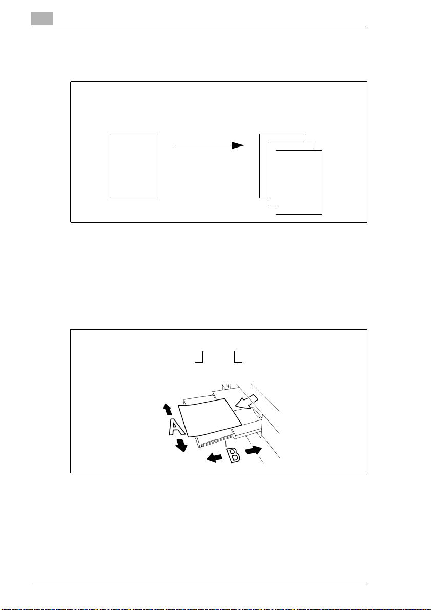
Original and copy
The original is the document being duplicated by the copy cycle.
Original
(document to be copied)
Copy cycle
enlarge,
reduce
sort.
Feeding direction
The feeding direction is the paper's path through the system.
Width and length
Whenever paper dimensions are specified in the Owner's Manual, the first
value always refers to the width of the paper (side A) and the second to
the length (side B).
(copy of the original document)
,
Copy
21 x 29.7 cm
Width of the paper
(side A)
Length of the paper
(side B)
1-6 Di850
Page 18
Introduction
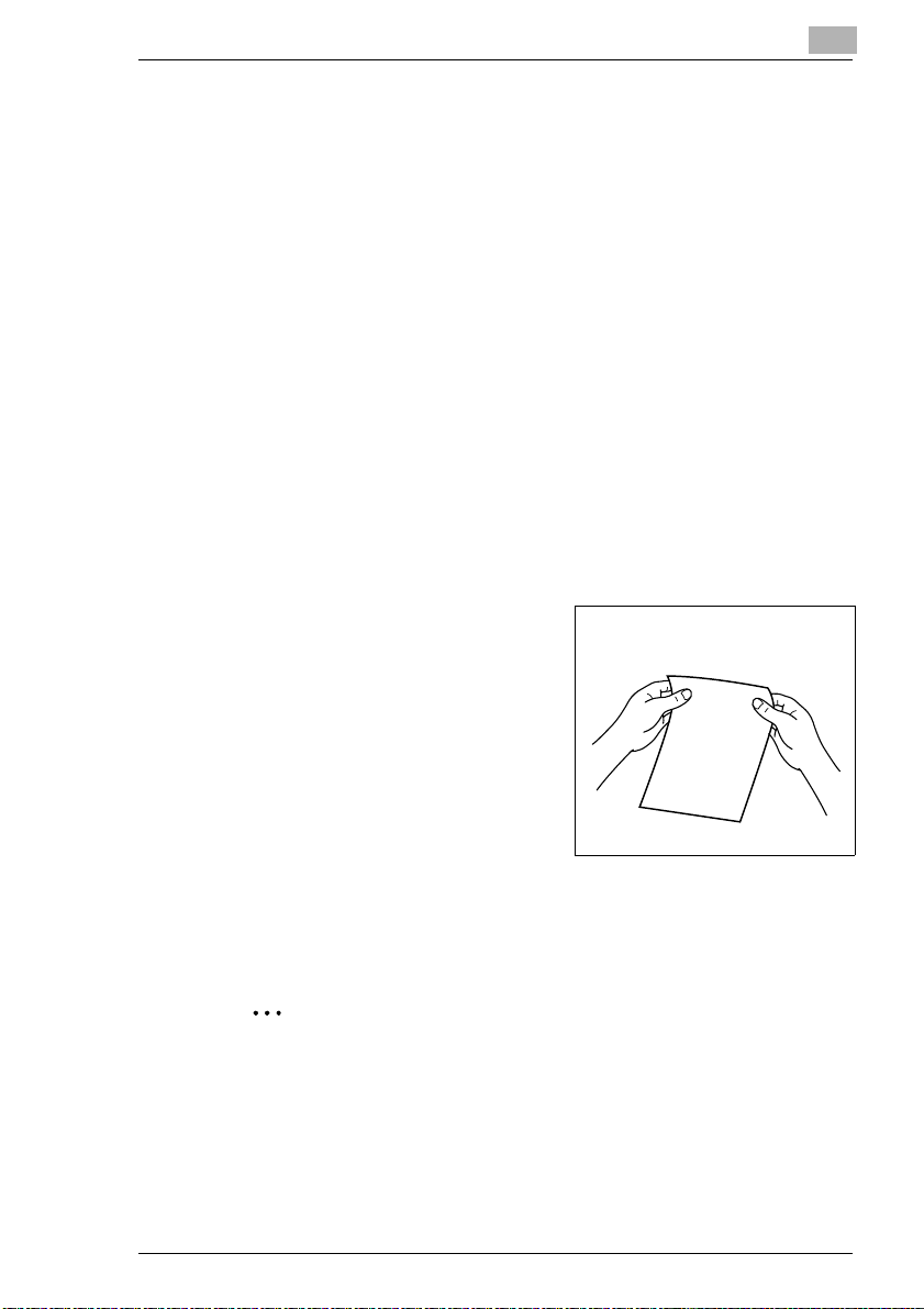
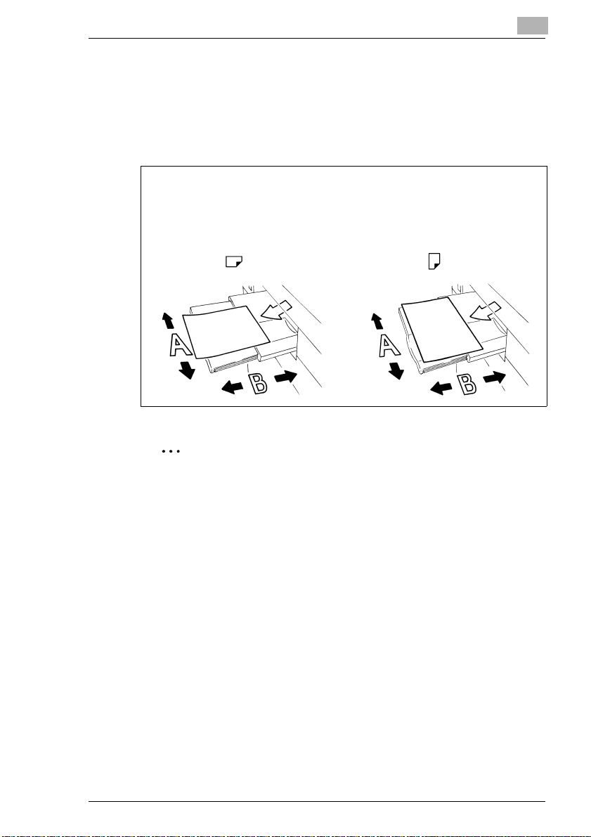
Lengthwise and crosswise
If side A of the paper format is shorter than side B, this is referred to as
lengthwise. The size label is specified with an “R” e.g. A4R.
If side A of the paper format is longer than side B, this is referred to as
crosswise. The size is not identified in any more detail, e.g. A4.
1
A4R A4
21 x 29.7 cm 29.7 x 21 cm
Lengthwise Crosswise
Size data with or without "R"?
Lengthwise sizes are specified with an "R". Sizes for which it is clear
which direction they have to be inserted, such as A3 (can only be fed
lengthwise), the "R" is omitted.
Di850 1-7
Page 19

1
1.4 Overview of System Features
The digital technology and the memory capacities of this system give it a
range of features that goes far beyond common copier functions.
The following pages provide an overview of the range of features offered
by this system.
General Features
All-Image Area
Copy originals without losing any of the edge.
Auto Layout
Automatically centers a copy on the copy paper.
Booklet
Combine A4 originals (1-2 or 2-2) into A5 or A4 booklets.
Chapter
Automatically copy previously specified chapter titles on right side sheets.
This feature is only available in duplex mode (1-2).
Combination
Copy 2, 4 or 8 originals onto a single copy paper sheet.
Contrast Range
Configure up to seven contrast ranges for four copy modes (automatic,
increase contrast, photo and text).
Dual Page
Copy two pages from an open book onto two single A4 pages (1-1) or
onto one A4 page (1-2). You can combine this feature with the Title and
Back features.
Duplex
Make 2-sided copies from 1- or 2-sided originals.
Energy Saver
Save energy using: auto low power and auto shut off modes.
Frame/Fold Erasure
Removes copy edges from 1 to 300 mm and/or fold marks from 1 to 99
mm, for example when copying from books.
Hole Punch for Finisher FN-7 (optional) or FN-115 (optional)
(only available with PK-3 or ZK-2 punch units – optional extras)
Punches a set of four holes into the finished copies.
Image Insert
Store image data from a document placed on the original glass. The
stored image data can be inserted into another original set, which has
been read in through the EDH.
Introduction
1-8 Di850
Page 20

Introduction
Image Shift
Create an image shift from 0 to 250 mm in 1 mm steps by shifting the
image area and if necessary also reducing it.
Interrupt Mode
Interrupt a copy cycle to copy urgent documents without waiting.
Job Status List
View an overview of the current copy job, other reserved copy jobs and
copy jobs that have already been processed. The status list can also be
used to change the order for processing pending copy jobs.
Magnification Ratio (fixed, variable)
Selecting a Magnification Ratio.Eight fixed and three user-defined
magnification ratios can be selected. Or choose a user-set zoom ratio
within the range of 25% to 400% in 0,1% increments.
Manual Shut Off
Manually shut off the copier to conserve energy.
Meter Count
Display a list with various meter counts: Total Count, Copy Count, Printer
Count and Maintenance Count.
Mixed Original (different-sized originals)
Copy a set of mixed size originals using the APS and AMS features.
AMS = Automatic magnification selection to copy mixed sizes onto a
desired paper size.
APS = Automatic paper selection to select copy paper based on the
originals and a magnification ratio.
Non-Image Area Erase
Copy with the original cover open without getting the familiar black edges.
Non STD Size for Bypass Tray
Specify special sizes for the bypass tray (to prevent faulty paper feeding).
Non STD Size Original
Specify nonstandard sizes for originals.This allows automatic selection of
an appropriate copy paper.
OHP Interleave
Insert blank or printed interleaves when copying onto transparencies.
Overlay
Copy two originals to one copy. For example, a letterhead and a text can
be copied together onto a page in one process.
Overlay Memory
Functions as with overlay mode. However, the overlay image is
permanently saved on the hard disk and can be recalled as required.
1
Di850 1-9
Page 21

1
Introduction
Overlay Memory
Store templates to use with the image overlay feature.
Paper Capacity
Total of 2,150 sheets (2 × 500 sheet drawer, 1 × 1,000 sheet drawer and
150 sheet bypass tray). Optionally available large capacity cassette holds
up to 4,000 sheets (80g/m²).
Program Job
Scan originals using various copier configurations and then make the
copies in a single process.
Program Memory
Store and call up to 30 copy job configurations.
Proof Copy
Test the copier settings using a proof copy before starting large copy jobs.
Repeat
Make multiple copies of a document onto one copy.
Reserve Jobs
Prepare further copier jobs while the copier is still busy processing the
output of a job.
Reverse Image
Make copies using inverse color values (black becomes white, white
becomes black).
Rotation Sort/Rotation Group
Output grouped or sorted copy sets, alternating lengthwise and crosswise.
Server Functions (Optional)
Store and call up copy jobs from a hard drive.
Sheet/Cover Insertion
Insert up to 30 separator sheets and/or cover and back sheets from one
of the paper drawers or from the bypass tray. The inserts, cover and back
sheets can be printed or blank as desired.
Simplex
Make 1-sided copies from 2-sided originals (2-1).
Stamp
Overprint copies with a stamp (set or page number) or print a watermark
on copies.
Staple
Specify a stapling position and the number of staples for each copy set.
Status Area
Shows the current system status for better control.
1-10 Di850
Page 22

Introduction
STD Size Original (Special)
Detection of standard sizes that usually are not recognized by an
automatic size detection unit.
Store Mode
Store originals that have been read in using the EDH or the original glass.
Tab Papers
Copying from and to tab papers gives an exact copy of items such as
register tab texts.
Tandem Operation (only with two systems)
Combine two systems into one unit. This lets you complete a copy job in
half the time.
Text/Photo Enhance
Improve exposure for optimizing the output of originals that contain text,
photographs or very light copy areas.
Trimmer Function for FN-7 Finisher
(only with optional TMG-2 trimmer unit)
stapled/folded booklet to make the edge even.
User-set Density
Define two user-defined density settings, which then can be called up on
the touch screen.
User-set Zoom Ratio
Define up to three user-defined zoom ratios, which then can be called up
on the touch screen.
Weekly Timer
Specify times at which the copier is to switch on and switch off. These
times can be specified as individual times or blocks of time. Holidays can
be scheduled for up to a year in advance using the calendar function.
Wide Size Paper
Process copy paper sizes that are larger than the standard sizes.
Z-fold for Finisher FN-7 (optional) or FN-115 (optional)
(only available with ZK-2 punch unit for Z-fold – optional)
Provides A3 copies with a Z-fold or folds B4 copies twice.
Z-Folded Original
Automatically feed in originals with Z folds using the EDH.
1
Trims the front edge of a
Di850 1-11
Page 23

1
Introduction
Automatic Features
Auto Low Power
Automatically reduces the power consumption after a specified idle time.
Auto Panel Reset
Automatically resets the copier settings to their defaults after a specified
time.
Auto Shut Off
Automatically shuts off the copier after a specified idle time.
Automatic Exposure Selection (AE)
The most appropriate exposure level is selected automatically based on
the originals being processed.
Automatic Magnification Selection (AMS)
Automatically selects a zoom ratio to copy mixed sized originals onto a
desired size of paper.
Automatic Paper Selection (APS)
Automatically selects the appropriate copy paper based on the originals
and a magnification ratio.
Automatic Tray Switching (ATS)
Automatically switches the paper trays when paper runs out. This enables
copying to be continued without interruption when a paper tray is emptied.
Rotation
Automatic rotation of the image area when the alignment of the originals
does not correspond to the paper alignment.
1-12 Di850
Page 24

Introduction
Finishing Features
Output with Finisher FN-7 (Optional) or FN-115 (Optional)
The following finishing modes are available:
G Main tray
G Sub tray
G Booklet output (only FN-7)
G Trim output (only FN-7 with installed
Output with Finisher FN-7 (optional) or FN-115 (optional) with Cover
Inserter C (optional)
Insert separating sheets and/or covers and staple manually.
Output without Finisher
The following finishing modes are available:
G Non Sort
G Rotation Sort
G Group
G Rotation Group
1
Non Sort, Sort, Staple and Group
Non Sort (face down), Non Sort (face up), Group (face down), Group
(face up)
Stapling & folding, folding
TMG-2 trim unit – optional)
Trimming
Copies are output in the order in which the originals were scanned.
Copies are output in the order in which the originals were read. The
copy sets are output alternating lengthwise and crosswise.
The copies are output in groups.
The copies are output in groups. The copy sets are output alternating
lengthwise and crosswise.
Di850 1-13
Page 25

1
Introduction
Features that can only be Set Up by a Service Technician
The following features can only be set up by a service technician. If you
want to have the following features set up for your use, contact your
technical representative.
Key Operator Password
The service technician can define a 4-digit key operator mode master
code. Access to key operator mode then can only be acquired after
entering the master code.
E.K.C. Master Key Code
The service technician can define an 8-digit E.K.C. master key code.
Access to the settings for the E.K.C. counter then can only be acquired
after entering the master code.
Weekly Timer Master Key Code
The service technician can define a 4-digit weekly timer master code.
Access to the settings for the weekly timer then can only be acquired after
entering the master code.
View the Weekly Timer Times on the Help Screen
The service technician can set up a key on the help screen to call up the
weekly timer times. This key then allows the user to view the weekly timer
times.
Touch Screen Contrast Settings on the Help Screen
The service technician can set up a key on the help screen to adjust the
contrast of the touch screen.
Messages: ADD TONER and PM CALL
The service technician can set up the system to display the following
messages automatically:
When the toner level in the bottle is very low:
When maintenance is required:
PM CALL
ADD TONER
.
1-14 Di850
Page 26

Introduction
WWW-Server Function
If the system is networked to a PC, you can view the current system status
on the PC using a web browser:
G
G Browser
G
G
1
URL
http:// (system IP address or Host Name)
Internet Explorer 5.0 or Netscape 4.0 or higher
Displayed items
Paper magazine configuration, accessories configuration etc.
Access to the WWW server
Via browser's URL
Di850 1-15
Page 27

1
Introduction
1-16 Di850
Page 28
Getting to Know Your System
2 Getting to Know Your System
2.1 System Overview
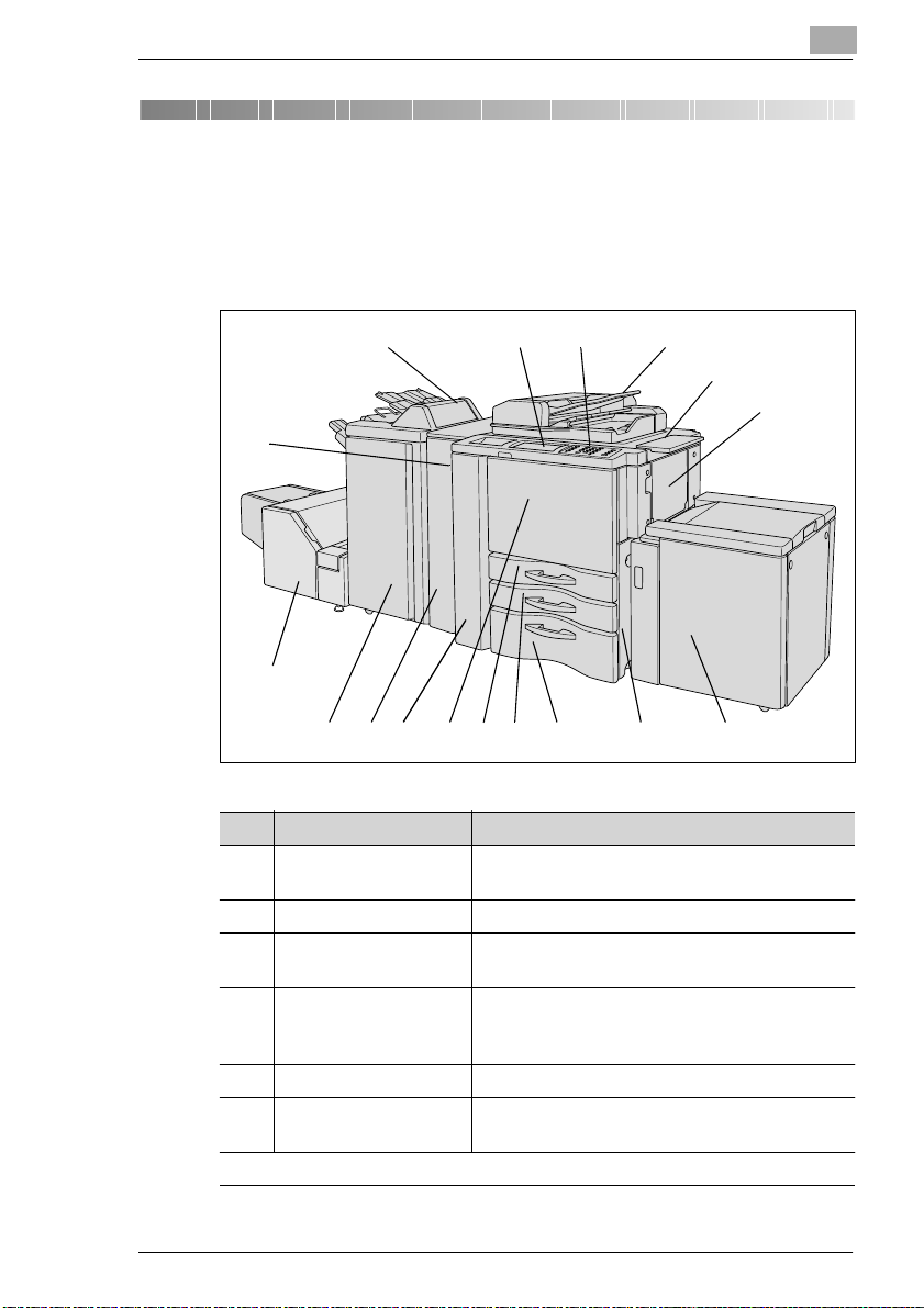
External System Overview
2
15
14
13
1112
Item Name Description
1 EDH Electronic Document Handling Tray
2 Document shelf Surface for placing originals o r copies
3 Bypass Tray Holds up to 150 sheets of standard paper
4 Large Capacity
Cassette LCC
(optional)
5 Right-hand door Open this door to clear paper misfeeds.
6 Tray 3 Universal drawer holds up to 1,000 sheets
...continuedonnextpage
16 17
8
Feeds in originals page by page automatically.
(80g/m²) or 1 sheet of special paper
Holds up to 4,000 sheets of standard paper
(80 g/m²)
(80g/m²) of various sizes
1
2
3
4567910
Di850 2-1
Page 29
2
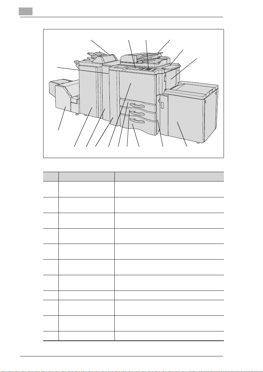
Getting to Know Your System
15
16 17
1
2
3
14
13
1112
Item Name Description
7 Tray 2 Universal drawer holds up to 500 sheets
8 Tray 1 Universal tray holds up to 500 sheets of paper
9 Front door Open this door to change the toner or clear a
10 Left door Open this door together with the front door to
11 Punch unit or Punch/Z-
fold unit (optional)
12 Finisher (optional) Used for regulated,stacked or sorted output of
13 Trimming Unit
(optional)
14 Power Switch Switches the system off
15 Cover Inserter
(optional)
16 LCD touch screen Touch-sensitive screen for viewing and
17 Control panel Provides the keys for operating the system
8
(80g/m²) of v arious sizes
(80g/m²) of v arious sizes
paper jam.
clear a paper jam.
Used for punching holes and Z-folding copies
copies
Used for trimming the front edge of a stapled/
folded booklet
Inserts cover sheets
modifying system jobs and settings
4567910
2-2 Di850
Page 30
Getting to Know Your System
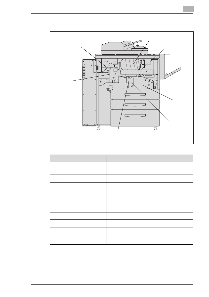
Internal System Overview
7
6
2
1
2
3
4
5
Item Name Description
1 Toner bottle • Contains the toner.
• Has to be replaced when toner runs out.
2 Toner Holder Holds the toner bottle
3 Transport Fuser Unit Transports the paper through the drum unit and
fixer unit. The transport carriage can be pulled
out to clear a paper jam.
4 Lever A Release this lever to clear a paper jam in this
5 Drum unit The copy image is generated on the drum unit.
6 Fixer unit Fuses the toner onto the copy paper.
7 RESET switch (for service personnel use only)
area.
Interrupts the power supply when the button is
pressed.
Di850 2-3
Page 31

2
2.2 Options (Accessories)
Finisher FN-115/FN-7
The finishers provide regulated output and sorting of copies.
The FN-115 provides the following functions:
G Sort
G Staple
G Group
The FN-7 provides these additional following functions:
G Folding
G Folding & Stapling (for creating booklets)
G Trimming (with installed TMG-2 trimming unit – optional)
CAUTION
Device damage by incorrect assessment of spacial requirements
The offset trays of a finisher move downward during the output cycle.
Objects below the offset trays may seriously damage them.
§ Do not place any objects below the offset trays of the finisher.
Getting to Know Your System
CAUTION
Danger of injury!
The Finisher FN-7 booklet output is fitted with a folding unit.
§ Do not reach into the booklet output of the Finisher when you are
removing folded or stapled booklets.
Do not exceed the capacity of the offset trays!
Do not exceed the capacity of the finisher offset trays, otherwise a
paper misfeed may occur. You should empty the offset trays during a
large copy job to avoid exceeding the capacity. For more information,
see page 9-15.
2-4 Di850
Page 32

Getting to Know Your System
Finisher FN-115/FN-7 (external overview)
2
2
3
1
2
1
6
FN-115 FN-7
Item Name Description
1 Main Tray Copies are output here
2 Top offset tray Copies are output here
3 Top offset tray paper
misfeed door
4 Finisher door Open this door to
5 Booklet output
(only FN-7)
6 Booklet Basket
(only FN-7)
4
•Non Sort
• Sort (with offset)
•Staple
• Group (with offset)
•Non Sort
• Group (printed side down/up)
Open this door to clear paper misfeeds
• clear a paper misfeed
• fill the staple cartridges
Copies processed using the “Folding” or
“Stapling & Folding” features are output here.
Catches copies discharged by the booklet
output.
3
45
Di850 2-5
Page 33

2
Getting to Know Your System
Finisher FN-115/FN-7 (internal overview)
1
2
3
4
5
6
1
2
3
4
5
6
7
8
6
6
9
9
Item Name Description
1 Lever for opening the
paper-jam door
2 Transport rollers Rotate the transport rollers to feed jammed
3 Lever for opening the
paper-jam door
4
5 Staple unit Staples copies and, with the FN-7, also turns
6 Handle on the stapler
unit
7 Lever for opening the
paper-jam door
8 Transport rollers Rotate the tr ansport rollers to transport jammed
9 Staple cartridges Replace the staple cartridges when the staples
Open the paper-jam door to remove jammed
paper
paper further
Open the paper-jam door to remove jammed
paper
them into booklets
Pull the stapler unit out by this handle, to
remove jammed paper or fill the staple
cartridges
Open the paper-jam door to remove jammed
paper
paper out of the staple unit
run out
FN-7FN-115
2-6 Di850
Page 34

Getting to Know Your System
Cover Inserter C for Finisher
The Cover Inserter is a paper feeding unit for the finishers. It can be used,
for example, to feed in cover stock for creating booklets.
Paper fed by the cover inserter is sent directly to the finisher; it does not
run through the copier. The paper fed from the cover inserter thus cannot
be printed during cover insertion.
2
3
2
1
Item Name Description
1 Control panel Keys for operating manually cover inserter B
2 Tray Place cover pages for automatic feed
3 Guide plates Ensure correct alignment of the paper stack
Di850 2-7
Page 35

2
Getting to Know Your System
Large Capacity Cassette (LCC) C-403N/C-404N
Additional paper tray with a capacity of up to 4,000 sheets (80 g/m²) of
paper.
1
2
3
2
3
1
4
4
5
6
6
7
5
7
C-403N C-404N
Item Name Description
1 Upper cover Open the top cover to add more paper
2 Left door Open this door to clear paper misfeeds
3 Lever for opening the
paper-jam door
4 Guide plates Ensure correct alignment of the paper stack
5 Button for lowering the
paper plate
6 Paper plate Automatically lifts the paper stack
7 Rear tray Ensures correct alignment of the paper stack
Open the paper-jam door to remove jammed
paper
Press this button to lower the paper plate and
refill with new paper
2-8 Di850
Page 36

Getting to Know Your System
TMG-2 Trimming Unit (optional for FN-7 Finisher)
The trimming unit lets you trim the front edge of stapled or folded booklets.
This ensures a smooth booklet edge.
CAUTION
Incorrect handling can cause damage to the system!
Incorrect handling can cause damage to the system. Observe the
following safety precautions to prevent system damage.
§ Never place any objects on or in the trimming unit.
§ Do not use the trimming unit for storing copy materials or other objects.
Always keep the tray cover closed!
It is not possible to start a copy cycle if the tray cover is not closed.
If the tray cover of the trimming unit is opened during a copy cycle, the
system stops the cycle automatically. This leads to a paper misfeed.
2
6
5
7
8
Item Name Description
1 Front right panel Open this panel to clear paper misfeeds
Di850 2-9
4
1
3
2
Page 37

2
Getting to Know Your System
Item Name Description
2 Front door Open the front door to clear a paper jam or to
empty the waste container
3 Drawer Receives the trimmed booklets
4 Tray Moves in steps to the left when booklets that
have been trimmed are output
5 Tray cover Open this cover to remove the completed,
trimmed booklets
6 Transport rollers Rotate the tr ansport rollers to transport jammed
paper out of the unit
7 Waste container Collects waste paper
8 Lever for opening the
paper-jam door
Open the paper-jam door to remove jammed
paper
2-10 Di850
Page 38

Getting to Know Your System
PK-3 Hole Punch Unit
Punches four holes in copies.
2
3
4
5
2
1
6
Item Name Description
1 Front door Open the front door
• to clear paper misfeeds
• to empty the waste container
2 Lever for opening the
paper-jam door
3
4 Transport rollers Rotate the transport rollers to feed jammed
5 Lever for opening the
paper-jam door
6 Waste container This is where the punch wastes are collected
Open the paper-jam door to remove jammed
paper
paper further
Open the paper-jam door to remove jammed
paper
Di850 2-11
Page 39

2
Getting to Know Your System
ZK-2 Punch/Z-fold Unit
Punches 4 holes into copies and/or Z-folds them.
3
4
5
2
1
6
Item Name Description
1 Front door Open the front door
• to clear paper misfeeds
• to empty the waste container
2 Lever for opening the
paper-jam door
3 Transport rollers Rotate the transport rollers to feed jammed
4 Handle Pull the unit out by the handle to clear a paper
5 Lever for opening the
paper-jam door
6 Waste container This is where the punch wastes are collected
Open the paper-jam door to remove jammed
paper
paper further
jam
Open the paper-jam door to remove jammed
paper
2-12 Di850
Page 40

Getting to Know Your System
Memory Expansions
Expand the memory capacity of the system. This allows more originals to
be read into the document memory, for example.
The following extended memory units can be purchased:
G 64 MB extended memory
G 128 MB extended memory
Pi8500 Printcontroller
Allows the system to be used as a printer.
2
Di850 2-13
Page 41

2
Getting to Know Your System
2.3 Safe Working with Your System
The improper use of your system may result in health hazards, electrical
shock or even fires. Please observe the following precautions for the safe
use of your system.
DANGER
Incorrect use of the system can result in fire and/or electrical shock!
The system is equipped with high-voltage components. Incorrect use of
the system may result in fire or electrical shock. Observe the following
safety precautions to prevent injury and system damage.
§ Never use flammable sprays, liquids or gasses near the system.
§ Never remove any safety equipment.
§ Do not touch areas designated with safety labels.
§ When you clear a paper jam etc. only touch the specially marked
areas.
§ Do not make design changes to the system.
§ Never unplug the system with wet hands.
§ Ensure that the power supply provides the correct supply voltage for
the system.
§ Never connect the system to a multiple-socket extension cord.
§ Do not place coffee cups, bottles or other containers with liquids on the
system. If liquids should ever accidentally be spilled or splashed into
the system, switch the system off immediately. Unplug the power
cable. Consult your technical representative.
§ Never insert paper clips, staples or other small pieces of metal into the
openings of the system. If metal items should ever accidentally fall into
the system, switch the system off immediately. Unplug the power
cable. Consult your technical representative.
§ Do not dismantle the system.
§ Allow only specially trained and authorized service personnel carry out
maintenance and repairs.
§ Never touch the drum unit.
2-14 Di850
Page 42

Getting to Know Your System
DANGER
Incorrect use of the system can result in fire and/or electrical shock!
The system is equipped with high-voltage components. Incorrect use of
the system may result in fire or electrical shock. Observe the following
safety precautions to prevent injury and system damage.
§ Note that the system is still switched on even when it is in low power
mode or in weekly timer mode.
§ Always switch off the system using the power switch if the system is
not going to be used for a long time.
§ Always unplug the power cable when the system is not going to be
used for a long time.
DANGER
Incorrect use of the power cable can result in fire and/or electrical
shock!
The system is equipped with high-voltage components. Incorrect handling
of the system's power cable may cause damage to the cable. This could
result in fire and/or cause electrical shock. Observe the following safety
precautions to prevent injury and system damage.
§ Be sure that the power cable is not damaged. If this is not the case,
switch off the system immediately. Unplug the power cable. Consult
your technical representative. Do not repair the network cable.
§ Do not pull directly on the power cable itself when unplugging the
power cable from the power outlet.
§ Do not move the system unless it is unplugged.
§ Never place heavy objects on the power cable.
§ Do not pull or bend the power cable.
§ Do not place the system on cables belonging to other devices.
§ Ensure that no cables of other devices get pinched in the system.
§ Be sure that the power cable sits correctly in the power outlet.
§ Always make sure that the power outlet is visible and accessible at all
times.
2
Di850 2-15
Page 43

2
Getting to Know Your System
§ Keep the network connector and the socket free from dust.
§ Never use any extension cords to connect the system to a power
outlet.
§ Never connect the system to a multiple-socket extension cord.
DANGER
System overheating can result in fire and/or electrical shock!
The system is equipped with high-voltage components. Incorrect use or
faulty operation of the system may cause the system to overheat. Observe
the following safety precautions to prevent injury and system damage.
§ Switch off the system immediately if it becomes unusually hot, smoke
rises from the system or you detect an unusual smell. Unplug the
power cable. Consult your technical representative.
§ If a fuse is tripped during a procedure, repeat the procedure. If a fuse
is tripped again, switch the system off immediately. Consult your
technical representative.
§ Be sure the fuses are sufficient for the nominal current ratings.
§ Always unplug the power cable when the system is not going to be
used for a long time.
CAUTION
Improper operation of the system can cause injury!
Incorrect operation of the system can lead to personal injury. Observe the
following safety precautions to prevent injuries.
§ Never touch the fusing unit. The fusing unit is hot.
§ When carrying out a procedure, touch only those parts of the system
that must be touched for this procedure as described in this manual.
§ Never put your hands into the booklet output of the finisher.
§ Never put your hands into the output tray of the finisher.
2-16 Di850
Page 44

Getting to Know Your System
CAUTION
Damage to the system by external influences!
External influences can cause damage to the system. Observe the
following safety precautions to prevent system damage.
§ Do not subject the system to vibrations.
§ Never bring any magnetized object near the system.
§ Never place any objects heavier than 6.8 kg and/or thicker than 30 mm
onto the system.
§ Do not put any objects under the main tray of the finisher. During the
output cycle, the finisher moves downward and can be damaged by
objects in its way.
CAUTION
Incorrect handling can cause damage to the system!
Incorrect handling can cause damage to the system. Observe the
following safety precautions to prevent system damage.
§ Do not open any doors on the system during printing.
§ Do not switch the system off during printing.
§ Ensure that the trays are not overloaded during copying. Observe the
specifications provided in the appendix! If necessary, remove finished
copies during the process to avoid overloading the trays.
§ Only use the copier and special paper that are expressly specified in
this manual.
§ Never use stapled or conductive paper.
2
CAUTION
A negligible amount of ozone is released during printing!
While this is not a health hazard, it may result in an unpleasant odor. It is
recommended that the room be well ventilated.
§ Locate the system in a well-ventilated room.
Di850 2-17
Page 45

2
Getting to Know Your System
Laser Safety
This system is equipped with a laser. If the system is operated in
accordance with the instructions in this manual, the laser poses no
possibility of danger.
The laser radiation is completely confined within the machine housing.
The laser beam cannot escape the housing at any time of operation.
This system is certified as a Class 1 laser product. This means that the
system does not generate any hazardous laser radiation.
Internal Laser Radiation
Mean radiation output:
1220 µW at the laser opening of the printer head.
Wave length: 665-695 nm
This system operates using a Class IIIb laser diode that emits an invisible
laser beam. The laser diode and scanning polygon mirror are incorporated
in the print head unit.
The print head unit is NOT A FIELD SERVICE ITEM. It may not be opened
under any circumstances.
Print head
The above illustration indicates the location of the print head of the
system.
2-18 Di850
Page 46

Getting to Know Your System
This is a semiconductor laser system. The maximum radiation capacity of
the laser diode is 20 mW. The wavelength is 665-695 nm.
Laser safety label on the back of the system
CLASS 1 LASER PRODUCT
APPAREIL A RAYONNEMENT
LASER DE CLASSE 1
LASER KLASSE 1
2
DANGER
Hazardous laser radiation!
Operating the system in a manner that does not conform to the
descriptions provided in this manual can lead to the release of hazardous
radiation.
§ Operate the system only in accordance with the instructions provided
in this manual.
Di850 2-19
Page 47

2
Getting to Know Your System
Safety Label
DANGER
Safety labels indicate hazard areas. Incorrect handling in hazard
areas can lead to serious personal injury and/or damage to articles.
§ Use this operating manual to familiarize yourself with the hazards
before carrying out any activity in a hazard area.
§ Clean soiled safety labels to keep them visible and legible. Replace
safety labels if they become illegible. For further information, consult
your technical representative.
This internal area is very
Cette zone interne est
Große Hitze im Innenbereich!
très chaude. Pour éviter
hot. To avoid getting
burned, DO NOT TOUCH.
CAUTION
ATTENTION
VORSICHT
PRECAUCION
ATTENZIONE
2
2
1
(on both sides of
the fusing unit)
(on the front
and inside the
fusing unit)
NICHT BERÜHREN, um
de se brûler, NE PAS LA
Verbrennungen zu
TOUCHER.
vermeiden!
(on both sides of the fusing unit)
CAUTION
Burn hazard!
The fusing unit is very hot.
Do not touch the fusing unit.
CAUTION
Danger of injury!
The fixing/transport unit is heavy.
Pull the unit out carefully and slowly.
Esta zona interior está
Questa area interna è
estremamente calda. Per
muy caliente. Para no
evitare di rimanere ustionati,
quemarse NO TOCAR.
NON IMMETTERVI LE MANI.
CAUTION
Danger of injury!
Do not place your hands between the
fixing/transport unit and the main
unit.
WARNING
DANGER
WARNUNG
ADVERTENCIA
AVVERTIMENTO
WARNING
This area generates
high voltage.
If touched, electrical
shock may occur!
DO NOT TOUCH!
2-20 Di850
Page 48

Getting to Know Your System
DANGER
Safety labels indicate hazard areas. Incorrect handling in hazard
areas can lead to serious personal injury and/or damage to articles.
§ Use this operating manual to familiarize yourself with the hazards
before carrying out any activity in a hazard area.
§ Clean soiled safety labels to keep them visible and legible. Replace
safety labels if they become illegible. For further information, consult
your technical representative.
2
Tra y 1
Tra y 3
FN-7 Finisher
(FN-7 only)
CAUTION
Danger of injury!
A roller unit is located in the
booklet output. Do not put your
hands in the output tray of the
booklet output.
Tra y 2
CAUTION
Danger of injury!
Do not place your hands
between the paper tray
and the main unit.
(FN-115/FN-7)
CAUTION
Danger of injury!
Do not put your hands into
the feed or output
chambers of the finisher.
(FN-115/FN-7)
CAUTION
Danger of injury!
Never place your hands on the output copier
paper stack when the Finisher copy tray is
moving upwards.
Di850 2-21
Page 49

2
Getting to Know Your System
System serial number
The serial number is located on a label at the following position:
Make a note of the serial number of your system in the table below. Please
keep this information at hand in the event of any questions for fast help in
the event of problems.
Model:
Serial No.:
2-22 Di850
Page 50

Getting to Know Your System
2.4 Transporting the System
If you need to transport the system, please consult your technical
representative.
2.5 Installing the System
Environmental Requirements
The optimal environmental requirements of the system are as follows.
G Temperature from 10°C to 30°C / 50 to 86°F
(maximum fluctuation of 10°C / 50°F per hour)
G Humidity of 10% to 80%
(maximum fluctuation of 20% per hour)
Installation Site
The installation site must meet the following requirements:
G an area that is dry and free of dust
G a level surface free of undue vibrations
G provision for good ventilation
G a location away from curtains or other easily-inflammable materials
G away from personnel so that no one is subjected to the direct exhaust
air of the system
The system must be protected from the following influences:
G splashing liquids
G direct sunlight
G strong temperature fluctuations
G direct air flow from heating or air conditioning units
2
CAUTION
Damage to the system by external influences!
The main tray of the finisher lowers during the output cycle. Objects
located under the main tray can damage the main tray.
§ Do not put any objects under the main tray of the finisher.
Di850 2-23
Page 51

2
Getting to Know Your System
Space required for System
CAUTION
Device damage by incorrect assessment of spacial requirements
Always ensure sufficient free space around the system. Too little space
can cause damage to the system, for example from overheating.
Furthermore operation is hindered by too little free space.
§ Leave sufficient space between the back of the device and the wall to
ensure adequate ventilation.
§ Do not put any objects under the main tray of the finisher. The main
tray lowers during the output cycle. Objects located under the main
tray can cause serious damage to the main tray.
Units in mm
400
1160
475
887
1762
400
1560
Di850
100 100
546321
1807
2337
887
386
530
Di850 + FN-115/FN-7 + C-403N
400
1160
1560
1845
120
775
120
950
775
1845
950
2-24 Di850
Page 52

Getting to Know Your System
2
Units in mm
950
400
150
1118
174
546
2831
887
3601
100
626
1560
1160
770
775
1845
120
Di850 + FN-7 + TMG-2 + PK-3/ZK-2 + C-404N
Storing Supplies
WARNING
Toner can be hazardous to your health!
Toner is harmful to your health.
§ If you get any toner on your hands, immediately wash them thoroughly
with soap and cold water.
§ Never dispose of an empty toner bottle in a fire. The remaining toner
left in the bottle can ignite and cause a hazardous situation.
Ensure that supplies are stored:
G in their original, sealed packaging
G protected from direct sunlight and heat sources
G in a cool, dry, dust-free location
G out of the reach of children
2.6 Connecting the System
Voltage and Frequency Tolerances
The system needs a reliable, consistent power supply. Please call your inhouse technical support if required.
G Voltage ± 10%
G Frequency ± 0.3%
Di850 2-25
Page 53

2
Getting to Know Your System
2.7 Switching the System on and off
Switching the System on
The power switch is located on the left side of the main unit.
§ Switch the power switch (POWER)
to the I position.
The warm-up phase (about 6
minutes) begins, during which
various warm-up indications are
displayed on the touch screen.
If the system will not let you
?
switch it on using the power
switch...
The system is equipped with an extra internal power switch
(RESET switch). This switch is only used by service and
maintenance personnel. For more information, see page 2-3.
§ Be sure that the RESET switch is set to the I position.
§ Do not use the RESET switch to switch the system on or off under
normal operating conditions.
Initial System Settings:
G Number of copies: 1
G Zoom ratio: 1:1
G EDH ON
G Copy mode: 1>1
G Auto exposure ON
G Auto paper select mode: ON
G Output mode: Non-sort,
output to main tray
The initial system settings can be modified in key operator mode. For
more information, see page 7-5.
Setting up reserve jobs during the warm-up phase!
You can set up reserve jobs even during the warm-up phase. For more
information, see page 3-19.
2-26 Di850
Page 54

Getting to Know Your System
Switching the System off
The power switch is located on the left side of the main unit.
§ Switch the power switch (POWER)
to the 0 position.
The touch screen and all LEDs on
the control panel turn off. The
system is switched off.
Weekly timer disabled!
The weekly timer is disabled when you switch off the system with the
power switch.
2
Di850 2-27
Page 55

2
Getting to Know Your System
2.8 Control Panel Keys and Indicators
Control Panel
123 4
Item Name Element Description
1 Program Memory Key Press this key to call or save system
settings.
2 Help Key Press this key to display the help
funct ion, which can also be used to call
up key operator mode
3 Mode Check Key Press this key to call up a display o f the
current copier settings.
4 10-Key Pad Keys Use to enter numerical values
5 Timer Indicator Is lit if the timer feature is active
6 Mode Key For switching between the system
modes:
•Copy
•Scan
•Print
7 Energy Saver Key Press this key to activate/deactivate an
energy saving mode.
8 Panel Reset Key Press this key to reset the system to
the default setting
. . . continued on next page
5
810111314
67912
2-28 Di850
Page 56

Getting to Know Your System
2
123 4
Item Name Element Description
9 Interrupt Key Press this key to interrupt or continue a
copy cycle.
10 C Key Press this key to reset the number of
copies.
11 Stop Key Press this key to stop a copy cycle.
12 Start Key Press this key to start a copy or scan
cycle.
13 Utility Key Press to display the meter count
display.
14 Proof Copy Key To output a test copy with the current
copy settings
5
810111314
67912
Di850 2-29
Page 57

2
Getting to Know Your System
Indicators and Keys on the Touch Screen
1
2
16
15
14
13
12
10
11
Item Name Element Description
1 Mode status Indicator Indicate that one of the following
modes is active:
• Tandem mode (master)
• Tandem mode (slave)
• HDD Store
• Original Direction
• Service
•90° Mode
2 Count/Set Indicator Shows the number of copies already
created and the specified number of
copies.
3 Status Key This key calls up functions used to
monitor and manage reserved jobs.
4 Special Originals Key This key is used to call up functions
such as
• Original Direction
• Text/Photo Mode
• Special Originals
5 Applications Key Used to call up various applications,
such as
• Auto Layout
•Dual Page
• Chapter Mode
6 Rotation OFF Key This key switches page rotation on or
. . . continued on next page
off.
9
3
4
5
6
7
8
2-30 Di850
Page 58

Getting to Know Your System
2
1
2
16
15
14
13
12
11
10
Item Name Element Description
7 Store Key Turns document memory on or off.
8 System Memory Indicator Shows the remaining available
9 Original counter Indicator Displays the number of originals read
10 Basic settings Keys /
11 Reserve Job
counter
12 Service messages Indicator Displays service messages, such as:
13 Output Keys These keys are used to select the
. . . continued on next page
Indicators
Indicator Shows the number of configured
memory capacity.
• when placed on the EDH:
every sheet drawn in increments the
counter by 1, regardless of
whether one or both sides are being
copied
• Loading onto the original glass:
every scan cycle increments the
counter by 1
Use these to select and view the initial
copier settings, such as
• Copy Mode
•Zoom ratio
•Contrast
reserve jobs
• Add toner
•PM call
finishing mode.
9
3
4
5
6
7
8
Di850 2-31
Page 59

2
Getting to Know Your System
1
2
16
15
14
13
12
11
10
Item Name Element Description
14 Output display Indicator Displays the selected finishing mode.
15 Job folder Key/
16 Messages and
status displays
Indicator
Indicator Displays the current messages and
• Used to select a reserve job
• Displays status messages regarding
a job
status values.
9
3
4
5
6
7
8
2-32 Di850
Page 60

Getting to Know Your System
2.9 Using the Touch Screen
The system is equipped with a touch screen. Touch screens react to
touch. Use the touch screen to change system settings and monitor
procedures.
§ Lightly touch one of the keys illustrated on the touch screen to select
functions or change settings.
2
CAUTION
Incorrect handling can cause damage to the system!
The surface of the touch screen is glass. Incorrect handling can damage
the touch screen.
§ Never place heavy objects on the touch screen.
§ Use care when touching the surface of the touch screen.
§ Do not apply strong pressure to the surface.
§ Avoid touching the surface of the touch screen with sharp objects.
Di850 2-33
Page 61

2
2.10 Adding Paper
The main screen shows the paper levels for each paper tray. You can see
how full a tray is from the indicator. If the indicator shows an arrow, that
paper tray is empty. If so, refill it with paper.
Note the following important information!
Paper Tray1
Capacity: up to 500 sheets (80g/m²)
Paper Tray 2
Capacity: up to 500 sheets (80g/m²)
Paper Tray 3
Capacity: Up to 1,000 sheets (80 g/m²)
Bypass Tray
Capacity: max. 150 sheets (80 g/m²)
Paper Drawer 4 - LCC (optional)
Capacity: Up to 4,000 sheets (80 g/m²)
Getting to Know Your System
max. 1 sheet of special paper
Inserting special papers!
When you are processing special papers, make sure that the paper
tray is set for that type of paper. For more information, see page 7-32.
2-34 Di850
Page 62

Getting to Know Your System
Refilling Trays 1, 2 and 3
Add paper to paper trays 1, 2 and 3.
These trays allow various paper sizes and alignments.
Carefully pull the drawer out as far
1
as it will go.
Lift the paper feed roller out of the
2
way.
Remove any paper that has been
3
left in the paper drawer. Slide the
edge guides completely out. Set the
back paper guide to
the desired size.
Fan the new paper.
4
Align the paper edges straight.
Load the new paper so that the side
5
that undulates upward is face up.
H Tray 1
up to 500 sheets (80 g/m²)
H Tray 2
up to 500 sheets (80 g/m²)
H Tray 3
up to 1000 sheets (80 g/m²)
2
Make sure not to exceed the
6
maximum paper filling level. The
paper stack must not be higher than
the red mark of the indicator.
Di850 2-35
Page 63

2
Getting to Know Your System
Adjust the guides so that they are
7
flush with the paper.
Lower the paper feed roller back in
8
place.
Carefully slide the paper tray back.
9
If you have changed the paper size,
the new size will be shown on the
main screen.
Loading tab papers!
If you want to process tab papers, insert them as illustrated in the
following figure. Ensure that the paper type “Tab Paper” is set to the
paper tray. For more information, see page 7-32.
1, 2, 3
Section 3
Management
Section 1
Introduction
1, 2, 3, 1, 2, 3, 1, 2, 3
Section 3
Section 3
Management
Section 3
Management
Management
Section 1
Introduction
Introduction
Section 1
Section 1
Introduction
2-36 Di850
Page 64

Getting to Know Your System
Adding Paper to Paper Tray 4 - C-403N (optional)
Add paper to paper tray 4.
The paper size in this paper tray is set to A4 by default. If you want to
change the paper size for this paper tray, contact your technical
representative.
Open the top cover of the tray.
1
Press the button to lower the paper
2
lifting plate to lower the plate
slightly.
Fan the new paper. Align the paper
3
edges straight.
Load the paper so that the side that
4
undulates upward is face down.
H up to 4,000 sheets (80 g/m²)
2
Repeat steps 2 to 4 until the tray is
5
full.
Make sure not to exceed the
6
maximum paper filling level. The
paper stack must not be higher than
the red mark of the indicator.
Close the top cover of the tray.
7
Di850 2-37
Page 65

2
Getting to Know Your System
Loading tab papers!
If you want to process tab papers, insert them as illustrated in the
following figure. Ensure that the paper type “Tab Paper” is set to the
paper tray. For more information, see page 7-32.
Section 1
Introduction
Section 1
Introduction
1, 2, 3
Section 1
Introduction
1, 2, 3, 1, 2, 3, 1, 2, 3
Section 1
Section 1
Introduction
Section 1
Introduction
Introduction
Section 1
Introduction
Section 1
Introduction
Section 1
Introduction
Section 1
Introduction
2-38 Di850
Page 66

Getting to Know Your System
Adding Paper to Paper Tray 4 - C-404N (optional)
Add paper to paper tray 4.
The paper size in this paper tray is set to A3 by default. If you want to
change the paper size for this paper tray, contact your technical
representative.
Open the top cover of the tray.
1
Press the button to lower the paper
2
lifting plate to lower the plate
slightly.
Fan the new paper. Align the paper
3
edges straight.
Load the paper so that the side that
4
undulates upward is face down.
H up to 4,000 sheets (80 g/m²)
2
Repeat steps 2 to 4 until the tray is
5
full.
Make sure not to exceed the
6
maximum paper filling level. The
paper stack must not be higher than
the red mark of the indicator.
Close the top cover of the tray.
7
Di850 2-39
Page 67

2
Getting to Know Your System
Loading tab papers!
If you want to process tab papers, insert them as illustrated in the
following figure. Ensure that the paper type “Tab Paper” is set to the
paper tray. For more information, see page 7-32.
Section 1
Introduction
Section 1
Introduction
1, 2, 3
Section 1
Introduction
1, 2, 3, 1, 2, 3, 1, 2, 3
Section 1
Section 1
Introduction
Section 1
Introduction
Introduction
Section 1
Introduction
Section 1
Introduction
Section 1
Introduction
Section 1
Introduction
2-40 Di850
Page 68

Getting to Know Your System
Filling the Bypass Tray
Insert paper into the bypass tray. Use the bypass tray to process special
paper.
Open the bypass tray on the right
1
side of the system.
If using large sized paper, pull out
2
the extender of the bypass tray.
2
Place the paper flush up against the
3
feed chamber of the bypass tray.
H Special papers, OHP
transparencies: max. 1 sheet
H Other:
up to 150 sheets (80 g/m²)
Slide the edge guides to fit the size of the inserted paper.
4
Processing special paper using the bypass tray!
You can use the bypass tray to process special paper, such as tab
papers, OHP transparencies and others. For more information, see
page 3-44.
Di850 2-41
Page 69

2
Getting to Know Your System
Loading tab papers!
If you want to process tab papers, insert them as illustrated in the
following figure. Ensure that the paper type “Tab Paper” is set to the
paper tray. For more information, see page 4-61.
1, 2, 3
Section 1
Section 1
Introduction
Introduction
Section 1
Introduction
Section 1
Introduction
1, 2, 3, 1, 2, 3, 1, 2, 3
Section 1
Section 1
Introduction
Section 1
Introduction
Introduction
Section 1
Introduction
2-42 Di850
Page 70

Getting to Know Your System
2.11 Adding Toner
WARNING
Toner can be hazardous to your health!
Toner is harmful if swallowed.
§ If you get any toner on your hands, immediately wash them thoroughly
with soap and cold water.
§ Dispose of the used toner bottle in an environmentally friendly
manner.
§ Keep toner bottles out of reach of children.
If there is too little toner in the system, a message is displayed on the
touch screen. Use only toner that is suitable for this system. If you have
questions, please contact your technical representative.
2
Add toner.
Open the front door on the system.
1
Gently lift the toner bottle holder a
2
little and flip it out towards the right.
Di850 2-43
Page 71

2
Pull the toner bottle latch forward.
3
Remove the empty toner bottle.
Tap the new toner bottle against a
4
hard surface. Then shake the toner
bottle gently.
This loosens any clumps of toner.
Getting to Know Your System
Remove the transparent plastic
5
closure from the toner bottle.
Place the toner bottle into its holder.
6
2-44 Di850
Page 72

Getting to Know Your System
Align the notch on the toner bottle
7
with the arrow on the system.
Push the toner bottle latch back.
8
The toner bottle latches in place.
Swing the holder back until it clicks
9
in place. Close the front door.
2
Di850 2-45
Page 73

2
Getting to Know Your System
2.12 Replenishing the Staple Supply
(only with FN-115/FN-7 Finisher – optional)
If the staple magazine runs out, a message is displayed on the touch
screen. Use only staples that are suitable for this system. If you have
questions, please contact your technical representative.
Adding Staples for the FN-115 Finisher (optional)
Fill a staple magazine with a staple cartridge.
Open the finisher door.
1
Carefully pull the stapler unit out.
2
2-46 Di850
Page 74

Getting to Know Your System
Pull the stapler head up a little to
3
unlatch it. Then pull the stapler head
forward along its guides.
Press in both the right and left
4
points marked on the stapler head.
Open the cover on the stapler head.
Remove the empty staple cartridge
5
out of the stapler head. Leave the
remaining staples in the stapler
head, otherwise the first copy set
after refilling it will not be stapled.
2
1
2
Insert a new staple cartridge into the
6
stapler head. The arrows must be
aligned over each other. Remove
the safety strips. Close the cover of
the stapler head.
2
Di850 2-47
1
Page 75

2
Place the stapler head back into the
7
stapler unit. Finally push the stapler
head down a little until it latches in
place.
Carefully push the stapler unit back
8
in.
Close the finisher door.
9
Getting to Know Your System
2
1
2-48 Di850
Page 76

Getting to Know Your System
Adding Staples for the FN-7 Finisher (optional)
Fill a staple magazine with a staple cartridge.
Open the finisher door.
1
Carefully pull the stapler unit out.
2
Pull the stapler head up a little to
3
unlatch it. Then pull the stapler head
forward along its guides.
2
1
2
Lift the stapler head up and out of its
4
holder.
Di850 2-49
Page 77

2
Remove the empty staple cartridge
5
out of the stapler head. Leave the
remaining staples in the stapler
head, otherwise the first copy set
after refilling it will not be stapled.
Insert a new staple cartridge into the
6
stapler head. The arrows must be
aligned over each other. Remove
the safety strips.
Getting to Know Your System
Place the stapler head back into the
7
stapler unit. Finally push the stapler
head down a little until it latches in
place.
2-50 Di850
Page 78

Getting to Know Your System
Carefully push the stapler unit back
8
in.
Close the finisher door.
9
2
Di850 2-51
Page 79

2
2.13 Monitoring the PM Count Time
Maintenance should be carried out after a certain number of copies have
been processed. You can read the time for the next maintenance call on
the PM counter.
When a maintenance interval is reached, a message will be shown
automatically on the lower left of the touch screen. When it does, contact
your technical representative to set up a maintenance visit.
Viewing the PM Count
View the time of the next maintenance interval.
Press the [UTILITY] key on the
1
control panel.
The counter list is displayed.
Press the [MODE CHECK] key on
2
the control panel.
The PM count is displayed on the
counter list.
Getting to Know Your System
Utility
Mode Check
2-52 Di850
Page 80

Getting to Know Your System
Printing the PM Count
Print the PM count screen.
Press the [UTILITY] key on the control panel.
1
The counter list is displayed.
Press the [MODE CHECK] key on the control panel.
2
The PM count is displayed on the counter list.
Press the [COUNTER MENU] key.
3
The default settings are displayed.
2
Select the paper tray containing the paper that you want the counter
4
list printed onto.
Press the [START] key on the control panel to start the printout of the
5
counter list.
The counter list is printed.
Closing the PM Count Screen
Close the PM count screen.
§ Press [EXIT] to return to the default settings.
The default settings are displayed again.
Di850 2-53
Page 81

2
2.14 Shutting Down the System
When shutting down the system for long periods of time, follow these
instructions:
G Remove the power plug from the outlet.
G Store the system in a dry, dust-free room.
G Ensure that the system is not subject to vibrations
Protect the system against:
G Splashing liquids
G Direct sunlight
G Strong temperature fluctuations
G Direct air flow from heating or air conditioning units
Getting to Know Your System
2-54 Di850
Page 82

Getting to Know Your System
2.15 Please Observe these Precautions
. . . when working with your system
Please observe the following precautions when using your system:
G Never place any objects heavier than 6.8 kg and/or thicker than 30 mm
onto the system.
G Never open the system or switch it off during a working cycle.
G Never bring magnetized objects or use flammable sprays near the
system.
G Never use sharp objects inside the open system
. . . when servicing and repairing the system
The system requires regular maintenance by a technician authorized by
Minolta.
Maintenance and repair work may be carried out by specially trained and
authorized service personnel only.
DANGER
Incorrect use of the system can result in fire and/or electrical shock!
The system is equipped with high-voltage components. Incorrect use or
faulty operation of the system may cause the system to overheat. Observe
the following safety precautions to prevent injury and system damage.
§ Do not dismantle the system.
§ Never remove any system parts.
§ Allow only specially trained and authorized service personnel carry out
maintenance and repairs.
§ If the service call message is displayed on the touch screen and the
system does not respond, write down the error code. Unplug the
power cable. Consult your technical representative.
2
Di850 2-55
Page 83

2
2.16 Proper Use of Your System
The system may only be used for the tasks described in this manual. Any
other applications are considered inappropriate.
Using the system incorrectly can lead to serious personal injury and/or
damage to products and articles. Claims and liability and/or guarantees
are voided by damage incurred through incorrect use.
Certain types of documents may not be copied for further use or with the
intent to pass copies of such documents off as the original.
These include:
G Money
G Stamps (cancelled or uncancelled)
G Personal identification cards
G Vehicle registration documents
G Copyrighted materials (without the permission of the copyright holder)
If you are unsure whether a certain document may be copied, please
consult the relevant public authorities.
Getting to Know Your System
2-56 Di850
Page 84

Initial Steps . . .
3 Initial Steps . . .
3.1 Basic Operator Steps
Entering the Number of Copies
Enter the number of sets of copies you want made.
§ Press the corresponding keys on
the 10-Key Pad.
The entered number of copies is
displayed in the upper right-hand
corner of the touch screen.
3
Did you enter an incorrect number?
?
§ Press the [C] key on the control
panel and enter the correct
number of copies.
Di850 3-1
Page 85

3
Initial Steps . . .
Start Cycle
Start a copy or scan cycle.
A cycle can be started only when the basic functions are displayed on the
touch screen.
§ On the control panel press the
[START] key.
The cycle starts.
Stop Cycle
Stop a copy cycle, e.g. to prevent further output of faulty copies.
§ Press the [STOP] key on the control
panel.
The copy cycle stops. A
confirmation dialog appears. Select
whether you want to interrupt the
cycle or continue it.
Reset System Settings
Reset the system to the system default setting.
§ Press the [PANEL RESET] key on
the control panel.
The system is reset to the system
default setting.
Automatic Reset of the System
In key operator mode, you can specify a time, after which the system
is automatically reset to its initial settings. For more information, see
page 7-51.
3-2 Di850
Page 86

Initial Steps . . .
3.2 Activating the System
Ending Energy Saving Mode
The system is in energy saving mode when the touch screen display is
hidden.
§ Press any key on the control panel to bring the copier out of energy
saving mode.
The touch screen display appears normal again. The system is ready
for operation.
Set period for energy saving mode
In key operator mode you can specify a period after which the system
is automatically switched to energy saving mode. For more
information, see page 7-50.
Ending Auto Shut Off
The system is in auto shut off mode if the LED on the [ENERGY SAVER]
control panel key is on and the touch screen indicator is off.
§ Press the [ENERGY SAVER] key
on the control panel to close the
mode.
The LED on the [ENERGY SAVER]
key on the control panel goes out.
The touch screen switches on
again. The system is ready for
operation.
3
Setting Period for Automatic Shut off
In key operator mode you can specify a period after which the system
is automatically switched off. For more information, see page 7-50.
Di850 3-3
Page 87

3
Initial Steps . . .
Interrupting Weekly Timer Mode
The weekly timer is enabled if the LED of the TIMER display on the control
panel is lit. Interrupt the weekly timer mode to make copies.
Press the [ENERGY SAVER] key on the control panel.
1
A message is displayed on the
touch screen.
Does the message prompt you
?
to enter a code?
The weekly timer is protected with a 4-digit weekly timer code.
§ Enter the correct code. Confirm your input by pressing [START].
Use the 10-Key Pad to enter the
2
number of hours (0-9) by which the
weekly timer should be delayed.
Confirm your input by pressing [START].
3
Use the 10-Key Pad to enter the
4
number of minutes (00-59) by which
the weekly timer should be delayed.
Input copy time
0 hour(s) 05 minute(s)
Input copy time
8 hour(s) 05 minute(s)
Input copy time
8 hour(s) 07 minute(s)
Confirm your input by pressing [START].
5
The system is ready for operation.
Position original in the EDH
face up
Protecting the weekly timer with a code
You can specify a 4-digit code for protecting the weekly timer. For
more information, see page 7-47.
3-4 Di850
Page 88

Initial Steps . . .
Reactivate the weekly timer when you are done copying.
§ Press and hold the [ENERGY SAVER] key on the control panel for
more than one second.
The LED of the TIMER display on the control panel lights up. The
touch screen switches off. The weekly timer is active again.
3
Di850 3-5
Page 89

3
Initial Steps . . .
Entering the E.K.C. Password
The system provides the ability to count copies and assign copy limits with
the aid of passwords. Use key operator mode to set up the passwords and
copy limits. For more information, see page 7-39.
If the plug-in counter (E.K.C.) is enabled, you cannot make copies until the
system is unlocked using an E.K.C. password.
To unlock the system, enter an E.K.C. password.
Enter your 8-digit E.K.C. password using the 10-Key Pad.
1
Confirm your input by pressing [START].
2
Your current copy data are displayed on the touch screen for about
3 seconds. The system is then ready for operation.
Is the code not accepted?
?
You have entered an incorrect code.
§ Enter the code again. If the code still is not accepted, talk to the
system administrator.
What happens if the copy limit is exceeded?
?
That depends on what has been set in key operator mode.
When you reach the copy limit . . .
§ . . . a message appears on the touch screen, stating that the copy
limit has been exceeded. You can still continue to make copies
beyond the copy limit.
or
§ . . . the current copy cycle is completed.
Once the copy cycle is finished you cannot make any more copies.
or
§ . . . the copy cycle is canceled immediately.
No other copies can be processed. Talk to the system
administrator.
3-6 Di850
Page 90

Initial Steps . . .
Leave the system locked when you are finished!
You should lock the system again when you have finished copying to
prevent anyone else using your cost center. Proceed as follows:
Press and hold [C] and press [UTILITY]. Your copy data will be saved.
The touch screen will show the message "Enter E.K.C. code". The
system is locked.
3
Di850 3-7
Page 91

3
Initial Steps . . .
3.3 Placing the Originals on the Original Glass
Originals that are not suitable for the document handling tray (EDH), can
be placed on the original glass manually.
CAUTION
Damage to the system by external influences!
The original glass can be damaged by heavy objects.
§ Never place any objects heavier than 6.8 kg onto the original glass.
§ Do not press originals on the original glass.
Note the following important information!
• Maximum original size: A3, single sheet or book
• Maximum original weight and thickness: 6.8 kg / 30 mm
Open the original cover.
1
Place the original face down on the
2
original glass.
Push the original into the upper right
3
corner of the original glass.
Align the document along the
4
positioning plate.
Is the original transparent?
?
§ Place a sheet of white paper
of the same size on top of the original.
Close the original cover.
5
Are you using AUTO Layout,
?
Dual Page, Edge Erasing or
Image Repeat with automatic
detection?
§ Then leave the original cover
open.
The feature can only be run
properly with the cover open.
3-8 Di850
Page 92

Initial Steps . . .
To avoid black edges on your copies . . .
If you are making single-sided copies from books, you can apply the
“Frame/Fold Erasure” or “Non-Image Area Erase” feature to prevent
unsightly black edges.
Which original sizes are to be recognized?
In key operator mode, you can specify which sizes you want the
system to detect automatically: A-sizes, inch sizes, AB-sizes or AB
and inch sizes.
For more information, see page 7-51.
3
Di850 3-9
Page 93

3
3.4 Feeding Originals Using the EDH
To save time, originals can be processed using the document handling
tray (EDH). It allows you to load up to 100 originals simultaneously (80g/
m²), which are then fed automatically one after the other.
Not all documents are suitable for the EDH. Use only suitable originals.
Unsuitable originals include:
G carbon paper, paraffin paper and other very thin paper,
G very thick paper,
G paper with items adhered to it or pieces cut out of it,
G translucent paper, OHP transparencies (overhead projector films),
G folded, curled paper
G punched, stapled or bound paper
§ Manually place originals that are not suitable for the EDH onto the
original glass. For more information, see page 3-8.
Which original sizes are to be detected automatically?
In key operator mode, you can specify which sizes you want the
system to detect automatically: A-sizes, inch sizes, AB-sizes or AB
and inch sizes.
For more information, see page 7-51.
Initial Steps . . .
3-10 Di850
Page 94

Initial Steps . . .
Loading Equal-Sized Originals into the EDH
Load up to 100 originals (80 g/m²) of the same size into the EDH. The
originals are fed in automatically one after the other.
Note the following important information!
• Original sizes: A3 , B4, F4 , A4R, A4, B5R, B5, A5R, A5 ,
• Types of originals: plain paper (50 to 130g/m²)
• Maximum capacity of the EDH: 100 originals (80g/m²)
Load up to 100 originals (80g/m²)
1
face-up into the EDH.
?
§ Insert the originals with the first
Make sure not to exceed the
2
maximum paper filling level. The
paper stack must not be higher than
the red mark on the filling level indicator.
3
11"×17", 8.5"×14", 8.5"×11", 8.5"×11"R,
5.5"×8.5", 5.5"×8.5"R
(297×432 mm to 140×216 mm)
Copying 2-sided originals?
page face-up in the EDH.
Push the originals flush up against
3
the feed chamber of the EDH.
Slide the document guide plates to
4
fit the size of the originals.
Do you want to scan more than 100 originals?
Use the “Program Job” feature (see page 5-27) or use the document
memory (see page 4-68).
Di850 3-11
Page 95

3
Initial Steps . . .
Loading Single Originals into the EDH (SDF)
When copying thick originals, place them in the EDH individually. Select
“SDF” as the copy mode.
Note the following important information!
• Original sizes: A3 , B4, F4, A4R, A4, B5R, B5, A5R, A5,
11"×17", 8.5"×14", 8.5"×11", 8.5"×11"R,
5.5"×8.5", 5.5"×8.5"R
(297×432 mm to 140×216 mm)
• Types of originals: 50 to 130 g/m² copy mode 2-1, 2-2
• Maximum capacity of the EDH: 1 original
Enable the “SDF” function.
1
For more information, see page 4-82.
Slide the guide plates to fit the size
2
of the original.
50 to 200 g/m² copy mode 1-1, 1-2
Always load only 1 original face-up
3
in the EDH.
Copying 2-sided originals?
?
§ Insert the originals with the first
page face-up in the EDH.
Push the original flush up against
4
the feed chamber of the EDH.
The original is fed in automatically
and scanned.
3-12 Di850
Page 96

Initial Steps . . .
Loading Mixed-Sized Originals into the EDH
Load up to 100 originals (80g/m²) of the different sizes into the EDH.
Select one of the following copy modes:
G “AMS” (Copy onto the same paper size) or
G “APS” (Copy the originals onto corresponding paper sizes)
Note the following important information!
• Original sizes: A3, B4 A4R, A4, B5, A5 (mixed)
• Types of originals: Plain paper (50 to 130 g/m²)
• Maximum capacity of the EDH: 100 originals (80 g/m²)
Enable the “AMS” function.
1
For more information, see page 4-52
or
Enable the “APS” function.
For more information, see page 4-58.
Insert the originals face-up into the EDH as follows:
2
H A3 and B4 lengthwise (short side up against the feed chamber)
H A4 and B5 either lengthwise or crosswise
H A5 lengthwise (if A5 mixed with B5R then load A5 crosswise)
3
B4, A4R, B5R, B5, A5 (mixed)
A4R, B5R, A5 (mixed)
B5R, A5R (mixed)
Make sure not to exceed the maximum paper filling
3
level. The paper stack must not be higher than the red mark on
the filling level indicator.
Align the originals to the back side
4
of the EDH.
Push the originals flush up against
5
the feed chamber of the EDH.
Slide the guide plates to fit the size
6
of the largest original.
Di850 3-13
Page 97

3
Initial Steps . . .
Place Z-Folded Originals in the EDH
Place up to 100 originals (80 g/m²) with Z-fold into the EDH. The originals
are fed in automatically one after the other.
Note the following important information!
• Original sizes: A3, B4, F4 , A4R, A4, B5R, B5, A5R, A5,
11"×17", 8.5"×14", 8.5"×11", 8.5"×11"R,
5.5"×8.5", 5.5"×8.5"R
(297×432 mm to 140×216 mm)
• Types of originals: Plain paper (50 to 130g/m²)
• Maximum capacity of the EDH: 100 originals (80g/m²)
Set the document feeder for Z-folded. For more information, see page
1
4-80.
Load up to 100 originals (80g/m²) face-up into the EDH.
2
Copying 2-sided originals?
?
§ Insert the originals with the first page face-up in the EDH.
Make sure not to exceed the maximum paper filling
3
level. The paper stack must not be higher than the red mark on
the filling level indicator.
Push the originals flush up against
4
the feed chamber of the EDH.
Slide the document guide plates to
5
fit the size of the originals.
3-14 Di850
Page 98

Initial Steps . . .
3.5 Checking the System Settings
Before starting any large jobs, you should check to make sure all settings
are correct. To do so, you have two options:
G Check system settings in check mode
G Process a proof copy
Check Mode Screen
The system settings are displayed in check mode. System settings that
are shown on a shaded key can be directly modified or released in check
mode.
A maximum of two pages are shown in check mode:
G 1st page – Basic & Special. Originals
G 2 nd page – Application Mode
3
You can switch pages using the arrow keys found on the lower edge of the
touch screen. These arrow keys, however, are displayed only if there are
features enabled in “Application Mode”.
Di850 3-15
Page 99

3
Changing Settings
Modify the system settings in check mode or release them.
Press the [MODE CHECK] key on
1
the control panel.
The touch screen then displays the
Check Mode screen containing the
settings for “Basic - & Special
Originals”.
Mode Check
Initial Steps . . .
Press the key for the setting that you wish to modify, e.g. [COPY
2
DENSITY].
The background of the selected key turns black.
Press the [CHANGE SETTING] key found on the lower edge of the
3
touch screen.
The basic options are displayed.
Is the [CHANGE SETTING] key dimmed?
?
The selected function cannot be modified, only released.
§ For more information, see page 3-17.
Change the system setting as desired.
4
Press the [MODE CHECK] key on the control panel to return to the
5
check mode screen.
Change any other settings, if necessary.
6
Press the [EXIT] key to end this step.
7
3-16 Di850
Page 100

Initial Steps . . .
The basic options are displayed again.
Releasing Settings
Releasing a setting is the same as disabling it.
Mark the feature that you want to release.
1
Press the [RELEASE SETTING] key found on the lower edge of the
2
touch screen.
A dialog field is displayed to confirm the release.
3
Confirm the release by pressing [YES].
3
The feature is released (switched off).
Release or change any other settings, if necessary.
4
Press the [EXIT] key to end this step.
5
The basic options are displayed again.
Di850 3-17
 Loading...